EP3854699B1 - Nutzlastkonfiguration eines kleinsatelliten - Google Patents
Nutzlastkonfiguration eines kleinsatelliten Download PDFInfo
- Publication number
- EP3854699B1 EP3854699B1 EP21152414.5A EP21152414A EP3854699B1 EP 3854699 B1 EP3854699 B1 EP 3854699B1 EP 21152414 A EP21152414 A EP 21152414A EP 3854699 B1 EP3854699 B1 EP 3854699B1
- Authority
- EP
- European Patent Office
- Prior art keywords
- spacecraft
- structural arrangement
- longitudinal axis
- mechanical linkages
- velocity vector
- Prior art date
- Legal status (The legal status is an assumption and is not a legal conclusion. Google has not performed a legal analysis and makes no representation as to the accuracy of the status listed.)
- Active
Links
Images






Classifications
-
- B—PERFORMING OPERATIONS; TRANSPORTING
- B64—AIRCRAFT; AVIATION; COSMONAUTICS
- B64G—COSMONAUTICS; VEHICLES OR EQUIPMENT THEREFOR
- B64G1/00—Cosmonautic vehicles
- B64G1/22—Parts of, or equipment specially adapted for fitting in or to, cosmonautic vehicles
- B64G1/64—Systems for coupling or separating cosmonautic vehicles or parts thereof, e.g. docking arrangements
- B64G1/641—Interstage or payload connectors
- B64G1/643—Interstage or payload connectors for arranging multiple satellites in a single launcher
- B64G1/644—Interstage or payload connectors for arranging multiple satellites in a single launcher arranged for independent deployment
Definitions
- This invention relates generally to a launch vehicle payload where the payload includes a large number of very small spacecraft, and more particularly to techniques for structurally supporting the spacecraft during launch and deploying the spacecraft following launch.
- the presently disclosed techniques relate to a launch vehicle payload system that includes a number of small spacecraft and to techniques for structurally supporting the spacecraft during launch and deploying the spacecraft following launch.
- the system may include at least one robotic manipulator.
- the at least one robotic manipulator may be configured to detach at least one of the plurality of spacecraft from the structural arrangement, and deploy the spacecraft by imparting a delta V to the spacecraft.
- the system may include a sensor and the at least one robotic manipulator may be configured to position the at least one spacecraft proximate to the sensor such that a physical inspection may be performed using the sensor.
- the system may include a debris management arrangement and the robotic manipulator may be configured to detach one or more of the mechanical linkages and secure the detached mechanical linkages to the debris management arrangement.
- a system 100 includes a plurality of small spacecraft 110 and a structural arrangement 120.
- the structural arrangement 120 is, advantageously, configured to provide the only load path between the plurality of spacecraft 110 and a launch vehicle upper stage 1050.
- the structural arrangement 120 is configured as a lightweight tree-like structure that includes at least one member 124 approximately aligned with the launch vehicle longitudinal axis 1001 (that may be referred to herein as a "trunk member") and a plurality of "branch" members 126.
- Each branch member 126 has an end portion that is substantially outboard from the longitudinal axis 1001. In the illustrated implementation, each branch member 126 is approximately orthogonal to the trunk member 124, but other arrangements are contemplated wherein the branch member 126 may be disposed at an acute angle to the longitudinal axis 1001.
- the system 100 includes a number of mechanical linkages 130.
- the structural arrangement 120 may be configured to include interfaces with which the mechanical linkages 130 may be coupled.
- Each mechanical linkage 130 is a spring-like coupling that provides substantial resistance to both compression and tension.
- each mechanical linkage 130 is detachably coupled at a first end with a first respective spacecraft 110 and is detachably coupled at a second end with either of: one of the plurality of branch members 126, the at least one trunk member 124, or a second respective spacecraft 110.
- the structural arrangement 120 conforms to the cylindrical/conical inner surface a launch vehicle fairing 1060 so as to efficiently utilize the interior volume of the launch vehicle fairing.
- the mechanical linkages 130 between the spacecraft 110 may be structurally modeled as mechanical springs configured to resist both compressive and tensile forces.
- a spring constant of the mechanical linkages 130 may be selected such that the system (structural arrangement 120, mechanical linkages 130 and spacecraft 110) exhibits a requisite degree of stiffness.
- the mechanical linkages 130 may also prevent physical contact between individual spacecraft 110 in the face of launch vibration and acoustic loads, thus preventing damage to the spacecraft 110.
- spacecraft 110 In the configuration illustrated in Figure 1 , 64 small spacecraft 110 are contemplated (16 spacecraft 110 disposed in each of three lower tiers 121, and 8 spacecraft 110 disposed in each of two upper tiers 123).
- the illustrated 3D lattice-like arrangement of spacecraft may be considerably more extensive than illustrated. As a result, a much greater number of very small spacecraft, for example one thousand or more nanosats, may be accommodated by the illustrated techniques.
- the spacecraft 110 are mechanically coupled, by way of the branch members 126 and the trunk member 124 to the launch vehicle upper stage 1050.
- the trunk member 124 extends vertically along the launch vehicle longitudinal axis 1001.
- the trunk member 124 may be the primary load-path between the lattice arrangement and the launch vehicle upper stage 1050.
- the system 100 may be assembled prior to launch from its individual components. For example, a desired number of branch members 126 may first be attached to the trunk member 124, forming a tree-like structural arrangement 120.
- the small spacecraft 110 may then be attached to the structural arrangement 120, using the mechanical linkages 130.
- Each small spacecraft 110 may be supported, by way of detachable couplings with the mechanical linkages 130 to form the illustrated three-dimensional lattice-like structure.
- some mechanical linkages 130 may couple one spacecraft 110 with a neighboring spacecraft 110, as may be better observed in View A-A.
- the spacecraft 110 may be detached from the structural arrangement 120 following ascent to orbit.
- the system 100 includes one or more robotic arms 250 configured to detach the spacecraft 110 from the structural arrangement 120.
- a robotic arm mounted on a free-flying spacecraft (not illustrated) that may be carried to orbit by the same launch vehicle as the many small spacecraft.
- This servicing craft could also be carried to orbit by a separate launch vehicle. In such a case, the servicing craft may be configured to perform orbital rendezvous and then dock with the launch vehicle carrying the small spacecraft.
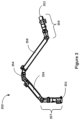
- the robotic manipulator 250 may include a robotic arm having two end effectors and a number of articulable joints disposed therebetween.
- Manipulator 350 includes first and second longitudinally elongated arms 356 and 358. Respective proximal ends of the arms 356 and 358 may be coupled together by means of an elbow joint 354. Articulator 357 including one or more articulable joints may be coupled with a distal end of arm 356. Similarly, articulator 359 may be coupled with a distal end of arm 358.
- one or both of the articulator 357 and the articulator 359 includes a pitch joint, a yaw joint, and a roll joint.
- First and second end effectors 351 and 352 may be mounted at the respective distal ends of the articulators 357 and 359.
- the mass of the robotic manipulator(s) 250 used to disassemble the lattice may be expected to be a small fraction of the aggregate total mass of the multiple spacecraft 110.
- the robotic manipulator 250 may be configured to detach mechanical linkages 130.
- the robotic manipulator 250 may move each small spacecraft 110, one by one, for example, a safe distance from the remaining spacecraft and provide the spacecraft 110 with a modest delta-V to assure positive separation.
- the robotic manipulator 250 may also be used to facilitate inspection of any or all of the small spacecraft 110 prior to separation.
- the robotic manipulator 250 may be configured to position a selected small spacecraft 110 in view of a camera or various other sensors.
- the robotic manipulator 250 may be used to secure the detached mechanical linkages to or within a debris management arrangement such as a storage bin or bins (not illustrated) to avoid creation of orbital debris.
- Figure 4 illustrates a conceptual view of a system 400 that includes a robotic manipulator 450 configured for use in a deployment process.
- the robotic manipulator 450 is illustrated as being in a stowed configuration; in Detail B, the robotic manipulator 450 is illustrated as being in a deployed configuration.
- a single robotic manipulator 450 is illustrated, but it will be appreciated that two or more robotic manipulators 450 may be contemplated in order to provide a desired degree of redundancy.
- one or all of the robotic manipulators 450 may have a range of motion which covers the entire interior of the launch vehicle fairing. Whether or not the robotic manipulator 450 has such a range of motion, the robotic manipulator 450 may be configured as a self-relocatable manipulator, such as described, for example, in U.S. Pat. No. 4,585,388 .
- the robotic manipulator 450 may include a first end effector 452, configured to facilitate the detachment, inspection and deployment of each individual spacecraft.
- the first end effector 452 may be configured to interface with a small spacecraft 410 and/or a mechanical linkage 430.
- the robotic manipulator 450 may sequentially grasp, with the first end effector 452, each small spacecraft 410 one at a time.
- the robotic manipulator 450 may be configured to detach the mechanical linkages 430 coupling a spacecraft 410 (1) from the supporting branches 426 and an adjacent spacecraft 410(2) before grasping the spacecraft 410 and moving it away from a first position (dashed line) to a second position (solid line).
- the second position may be a location from which the spacecraft 410(1) is to be separated (deployed) from the system 400.
- the system 400 is configured to perform one or more of the following additional processes before the spacecraft 110(1) is deployed.
- the system 400 includes a module 460 for inspection, testing and/or servicing of the spacecraft 110.
- the module 460 includes a debris management arrangement 462, a second end effector 464, and an inspection station 466.
- the second position accordingly, may be proximate to the inspection station 466 which may include a sensor (e.g., a camera or other imager) for physical inspection of the spacecraft 410(1).
- the second position may also be proximate to the second end effector 464.
- the robotic manipulator 450 may be configured to place the spacecraft 410(1) so as to engage the second end effector 464.
- the second end effector 464 may be configured to grasp the spacecraft 410(1), following which the robotic manipulator 450 may disengage from the spacecraft 410(1) and proceed with other tasks while the spacecraft is held in place by the second end effector 464.
- the robotic manipulator 450 may grasp and detach individual mechanical linkages 430 from the spacecraft 410(1), and secure the detached mechanical linkages 430 to the debris management arrangement 462.
- the debris management arrangement may be a storage bin and securing the detached mechanical linkages 430 to the debris management arrangement 462 may include placing the detached mechanical linkages 130 inside the storage bin. As a result, creation of orbital debris may be avoided.
- the storage bin 462 may also be used to dispose of spacecraft which have failed the physical inspection procedure.
- the module 460 may further include interfaces by which checkout and pre-deployment procedures for the spacecraft 410 may be accomplished, including, for example, mechanical or electrical subsystem checkouts.
- the robotic manipulator 450 may reengage the spacecraft 410 which may then be released from the second end effector 464.
- the robotic manipulator 450 may then proceed to deploy the spacecraft 410 through a combination of an axial movement and release, similar to a "throwing mechanism".
- the release may be timed such that the arm will provide the desired delta-V to the spacecraft 410.
- the robotic manipulator 450 may move on to the next spacecraft in sequence.
- the structural arrangement 420 may include propulsion capability and/or remain attached to a launch vehicle upper stage that has propulsion capability. In such implementations, the structural arrangement, following deployment of the smallsats, may be deorbited by the onboard propulsion capability.
- Figure 5 illustrates an example implementation that includes 16 tiers, each tier including a number of smallsats 510. More particularly, in the illustrated implementation, nine lower tiers 521 each include 72 smallsats 510, three intermediate tiers 523 each include 60 smallsats 510; two intermediate tiers 525 each include 48 smallsats 510; one intermediate tier 527 includes 36 smallsats 510; and one upper tier 529 includes 24 small sets 510. Thus, in the illustrated implementation, as many as 984 smallsats 510 may be accommodated.
- Figure 6 illustrates a process flow diagram for deploying a plurality of spacecraft from an orbiting system.
- the method 600 may start, at block 610, by deploying a first one of the plurality of spacecraft from the orbiting system.
- the method may continue, at block 620, by deploying a second one of the plurality of spacecraft.
- the orbiting system includes the plurality of spacecraft and a structural arrangement providing a load path between a launch vehicle upper stage and the plurality of spacecraft. Each spacecraft is mechanically coupled with the launch vehicle upper stage only by the structural arrangement.
- the structural arrangement includes at least one trunk member that is approximately aligned with the longitudinal axis of the launch vehicle upper stage, a plurality of branch members, each branch member being attached to the trunk member and having at least a first end portion that is substantially outboard from the longitudinal axis, and a plurality of mechanical linkages, each linkage coupled at a first end with a first respective spacecraft and coupled at a second end with one of the plurality of branch members, the trunk member or a second respective spacecraft.
- Figure 7 illustrates a process flow diagram for deploying the spacecraft from the orbiting system, according to some implementations.
- the method 700 may be executed as part of one or both of block 610 and block 620 of the method 600 where the orbiting system includes a robotic manipulator as described above.
- the method 700 may start, at block 710, with detaching, using the robotic manipulator, each respective second end of the mechanical linkages coupled with the spacecraft.
- the method 700 may continue, at block 720 with grasping the spacecraft with the robotic manipulator.
- the robotic manipulator may be configured to deploy the spacecraft by imparting a delta V to the spacecraft relative to the orbiting system. Accordingly, the method 700 may continue at block 760 imparting a relative motion to the spacecraft and, at block 770, releasing the spacecraft.
- one or more of additional process block 730, 740 and 750 may be executed prior to block 760.
- the orbiting system includes a sensor, and block 730 may be executed, so as to perform a physical inspection of the spacecraft using the sensor.
- the robotic manipulator may optionally be used to detach each respective first end of the mechanical linkages coupled with the spacecraft.
- the orbiting system includes a debris management arrangement, and the method 700 optionally includes executing block 750 so as to secure detached linkages to the debris management arrangement.
- two or more smallsats may be deployed simultaneously.
- the two or more smallsats may be coupled together with mechanical linkages at the time of deployment.
- the two or more smallsats may share a common propulsion system.
- a system including a plurality of small spacecraft and a structural arrangement may be configured to detach at least one of the plurality of spacecraft from the structural arrangement, and deploy the spacecraft by rotating or translating the structural arrangement.
- a system 800 includes a plurality of small spacecraft 810 and a structural arrangement 820.
- the structural arrangement 820 is, advantageously, configured to provide the only load path between the plurality of spacecraft 810 and the launch vehicle upper stage 1050.
- the structural arrangement 820 is configured as a lightweight tree-like structure that includes at least one trunk member 824 approximately aligned with a longitudinal axis 801 and a plurality of branch members 826.
- Each branch member 826 has an end portion that is substantially outboard from the longitudinal axis.
- each branch member 126 is approximately orthogonal to the trunk member 824, but other arrangements are contemplated wherein the branch member 826 may be disposed at an acute or obtuse angle to the longitudinal axis 801.
- the system 800 includes a number of mechanical linkages 830.
- the structural arrangement 820 may be configured to include interfaces with which the mechanical linkages 830 may be coupled.
- Each mechanical linkage 830 is a spring-like coupling that provides substantial resistance to both compression and tension.
- each mechanical linkage 830 is detachably coupled at a first end with a first respective spacecraft 810 and coupled at a second end with a respective one of the plurality of branch members 826.
- the structural arrangement 820 may conform to the cylindrical/conical inner surface of a launch vehicle fairing so as to efficiently utilize the interior volume of the launch vehicle fairing.
- the mechanical linkages 830 between the spacecraft 810 may be structurally modeled as mechanical springs configured to resist both compressive and tensile forces.
- a spring constant of the mechanical linkages 830 may be selected such that the system (structural arrangement 820, mechanical linkages 830 and spacecraft 810) exhibits a requisite degree of stiffness.
- the mechanical linkages 830 may also prevent physical contact between individual spacecraft 810 in the face of launch vibration and acoustic loads, thus preventing damage to the spacecraft 810.
- a mechanical coupling between each branch member 826 and a corresponding surface of a spacecraft 810 includes two or more mechanical linkages 830.
- each such mechanical coupling includes four mechanical linkages 830.
- spacecraft 810 In the configuration illustrated in Figure 8 , 72 small spacecraft 810 are contemplated (12 spacecraft 810 disposed in each of five lower tiers 821, and 6 spacecraft 810 disposed in each of two upper tiers 823). As indicated above, a 3D lattice-like arrangement of spacecraft may be considerably more extensive than illustrated. As a result, a much greater number of very small spacecraft, for example one thousand or more nanosats, may be accommodated by the present disclosure.
- the spacecraft 810 are mechanically coupled, by way of the branch members 826 and the trunk member 824 to the launch vehicle upper stage.
- the trunk member 824 extends vertically along the longitudinal axis 801.
- the trunk member 824 may be the primary load-path between the lattice arrangement and the launch vehicle upper stage.
- the spacecraft 810 may be separated (deployed) from the structural arrangement 820, upon achieving orbit, without necessarily relying on a robotic manipulator.
- deployment may be initiated by orienting the structural arrangement 820 such that the longitudinal axis 801 is approximately transverse to a direction of orbital velocity vector 802 and causing the structural arrangement 820 to rotate about the longitudinal axis 801 (Detail C).
- a centrifugal pseudo force will be experienced by the spacecraft 810, directed radially outward from the longitudinal axis 801.
- a selected one or more spacecraft 810 may accordingly be separated passively from the structural arrangement 820, by disengaging the mechanical linkages 830 coupling the selected spacecraft 810 with the structural arrangement 820.
- two spacecraft 810, spacecraft 810(1) and 810(2) may be deployed approximately simultaneously, in opposite directions, parallel to the orbital velocity vector 802.
- each spacecraft will drift away from each other and from the structural arrangement 820.
- the disengaged mechanical linkages 830 may be configured to remain with the structural arrangement 820 when the spacecraft are separated, thereby avoiding creation of orbital debris.
- an additional two spacecraft 810, spacecraft 810(3) and 810(4) may be similarly deployed approximately simultaneously, in opposite directions, parallel to the orbital velocity vector 802.
- each spacecraft will drift away from each other and from the structural arrangement 820.
- the disengaged mechanical linkages 830 may be configured to remain with the structural arrangement 820 when the spacecraft are separated, thereby avoiding creation of orbital debris.
- an additional two spacecraft 810, spacecraft 810(5) and 810(6) may be similarly deployed approximately simultaneously, in opposite directions, parallel to the orbital velocity vector 802. It may be observed that spacecraft 810(5) and 810(6) are outboard of, respectively spacecraft 810(7) and 810(8).
- Mechanical linkages 830 associated with such outboard spacecraft e.g., mechanical linkages 830(6) and 830(7) may be configured to be in tension while coupled with a respective spacecraft and to retract naturally once the respective spacecraft are deployed.
- an unobstructed path for deployment of inboard spacecraft 810(7) and 810(8) may be passively achieved.
- the deployment path for inboard spacecraft 810(7) and 810(8) may be further passively improved by configuring one or more of the branch members 826 as flexures.
- the branch members 826 may be configured to flex in opposite directions (i.e., outer ends of upper branch members may flex upward, outer ends of lower branch members may flex downward).
- an additional two spacecraft 810, spacecraft 810(7) and 810(8) may be similarly deployed approximately simultaneously, in opposite directions, parallel to the orbital velocity vector 802.
- Figure 10 illustrates some design considerations for spring constant selection for mechanical linkages coupling the spacecraft to branch members.
- the mechanical linkages may be interchangeable, which would save procurement, labor and other costs.
- the period of oscillation of all spacecraft would be similar if the same spring constant were applied throughout the configuration.
- all spacecraft may undergo synchronized oscillations, which could damage the supporting structure.
- mechanical linkage spring constants may be selected so as to avoid rotational motions of a spacecraft around an axis transverse to the longitudinal axis when the launch vehicle is under thrust and is generating vibrations.
- mechanical linkages coupling an upper surface of the spacecraft with a branch member above the spacecraft may be configured to have the same spring constant, k U ; similarly, all mechanical linkages coupling a lower surface of the spacecraft with a branch number below the spacecraft on the bottom of a particular spacecraft may be configured to have the same spring constant, k L .
- Use of a consistent spring constant is also advantageous to keep the spacecraft level when they are at rest with respect to the supporting structure, for example when the launcher is not applying thrust.
- the launch vehicle upper stage may be configured to rotate around its longitudinal axis to facilitate deployment of the spacecraft.
- the spacecraft will be displaced radially outward, away from the longitudinal axis and trunk member of the supporting structure.
- the displacement should be entirely transverse to the longitudinal axis avoid any significant displacement parallel to the longitudinal axis.
- the spring constant k U of the upper mechanical linkages and the spring constant k L of the lower mechanical linkages on each spacecraft may be configured to be the same (k 1 ).
- the upper mechanical linkages on the lower mechanical linkages may be configured to have approximately the same length
- lengths x 1 and x 2 would be about the same when the launch vehicle is not under thrust and is under weightless or zero-g conditions because the upper and lower springs will have the same similar length and spring constant to satisfy the conditions above.
- the lengths would also be about the same when the launcher, in zero-g conditions is rotating to support deployment of the spacecraft.
- the launcher is under thrust or is at rest on the surface of Earth prior to launch the lengths would differ, making x 1 longer and x 2 shorter as a result of the upper mechanical linkages experiencing tension in the lower mechanical linkages experiencing compression.
- the spring constants of mechanical linkages associated with opposite pairs of spacecraft that are simultaneously separated may also need to be similar to avoid a significant disturbance of the supporting structure when deployment occurs.
- the mechanical linkages of spacecraft disposed outboard of other spacecraft in a common tier may be configured retract upon deployment such spacecraft, as described above.
- the mechanical spacecraft proximal to the longitudinal axis need not retract upon deployment of such spacecraft. Therefore, these mechanical linkages may be configured to have significantly different characteristics from the mechanical linkages of the outboard spacecraft.
- a spring constant k 2 for mechanical linkages associated with an inner spacecraft springs may be configured to be lower than a spring constant k 1 of mechanical linkages associated with an outer spacecraft.
- the springs may be configured to have a longer natural length than those on the outer spacecraft.
- the spring constant of mechanical linkages associated with all outer spacecraft could have the same constant k 1 and the spring constant of mechanical linkages associated with all inner spacecraft could have the same spring constant k 2 .
- four-point separation concept may be incorporated, in which, for each spacecraft, four mechanical linkages couple an upper surface of the spacecraft with a branch member above the spacecraft and four mechanical linkages couple a lower surface of the spacecraft with a branch number below the spacecraft.
- damping may be included to prevent an undesirable increase in the amplitude of the oscillatory motion of the spacecraft.
- damping would tend to increase the time for the springs on the outer spacecraft to retract and provide clearance for deployment of inner spacecraft and a deployment sequence may be configured to provide sufficient time between deployment of outer spacecraft on a given tier and inner spacecraft on that tier for the springs to sufficiently retract.
- the period of rotation is expected to exceed ten seconds during this spacecraft deployment. Pairs of spacecraft would be deployed no more than once every half-rotation so that the motion of the separated spacecraft is approximately parallel to the direction of orbital motion. Delaying separation of the next pair by one-half or more rotations may be considered to provide sufficient time for the springs to retract.
- the spin rate of the launch vehicle may be reduced as spacecraft are in order to reduce the risk that later-separated spacecraft overtake a previously separated spacecraft.
- an inner spacecraft will not overtake an outer spacecraft because inner spacecraft spin speed, as measured in meters per second, would always be less than that of the outer spacecraft if the launcher were rotating at a constant rate. This is because the radius of rotation of the inner spacecraft is less than that of the outer spacecraft.
- the upper spacecraft are the first to be separated and are inner spacecraft.
- the launcher rotation might be set to a higher rate for these spacecraft to avoid outer spacecraft separated later from catching up with them.
- An alternative would be to allow extra time between these first few separation events and the deployment of the remainder of the spacecraft.
- Figures 11A and 11B illustrate an example of a further implementation in which a need for a robotic manipulator may be avoided.
- a system including a plurality of small spacecraft and a structural arrangement may be configured to detach at least one of the plurality of spacecraft from the structural arrangement, and deploy the spacecraft by rotating the structural arrangement.
- a system 1100 includes a plurality of small spacecraft 1110 and a structural arrangement 1120.
- the structural arrangement 1120 is, advantageously, configured to provide the only load path between the plurality of spacecraft 1110 and the launch vehicle upper stage 1050.
- the structural arrangement 1120 is configured as a lightweight tree-like structure that includes at least one trunk member 1124 approximately aligned with a longitudinal axis 1101 and a plurality of branch members 1126. Each branch member 1126 has an end portion that is substantially outboard from the longitudinal axis.
- the system 1100 includes a number of mechanical linkages 1130.
- the structural arrangement 1120 may be configured to include interfaces with which the mechanical linkages 1130 may be coupled.
- Each mechanical linkage 1130 is a spring-like coupling that provides substantial resistance to both compression and tension.
- each mechanical linkage 1130 is detachably coupled at a first end with a first respective spacecraft 1110 and coupled at a second end with a respective one of the plurality of branch members 1126.
- spacecraft 1110 In the configuration illustrated in Figure 11 , 72 small spacecraft 1110 are contemplated (12 spacecraft 1110 disposed in each of five lower tiers 1121, and 6 spacecraft 1110 disposed in each of two upper tiers 1123).
- the spacecraft 1110 may be separated (deployed) from the structural arrangement 1120, upon achieving orbit, without necessarily relying on a robotic manipulator.
- deployment may be initiated by orienting the structural arrangement 1120 such that the longitudinal axis 1101 (Detail L) is approximately aligned with a direction of orbital velocity vector 1102 and causing the structural arrangement 1120 to rotate about an axis 1103 that is approximately transverse to the longitudinal axis.
- a centrifugal pseudo-force will be experienced by the spacecraft 1110, directed radially outward from the transverse axis 1103.
- a selected one or more spacecraft 1110 may accordingly be separated passively from the structural arrangement 1120, by disengaging the mechanical linkages 1130 coupling the selected spacecraft 1110 with the structural arrangement 1120.
- a spacecraft 1110(1) is shown being deployed approximately in a direction approximately parallel to the orbital velocity vector 1102. As a result, the spacecraft 1110(1) will drift away from the structural arrangement 1120.
- branch member 1126 may be configured articulate away from an intended deployment path of the spacecraft 1110(1).
- branch members 1126 may be hingedly coupled with the structural arrangement 1120, such that the branch member may be rotated from a first direction transverse to the longitudinal axis to a second direction approximately parallel to the longitudinal axis.
- the disengaged mechanical linkages 1130 may be configured to remain with the structural arrangement 1120 when the spacecraft are separated, thereby avoiding creation of orbital debris.
- an additional spacecraft 1110(3) may be similarly deployed in a direction approximately parallel to the orbital velocity vector 1102. As a result, the spacecraft 1110(3) will drift away from the structural arrangement 1120.
- spacecraft 1110(3) may be similarly deployed in a direction approximately parallel to the orbital velocity vector 1102.
- an additional spacecraft 1110(4) may be similarly deployed in a direction approximately parallel to the orbital velocity vector 1102.
- successive tiers of spacecraft 1110 are deployed in a sequence such that spacecraft farther from the axis of rotation (axis 1103) are deployed prior to spacecraft that are closer to the axis 1103. It should also be observed that, as spacecraft are deployed, the location of axis 1103 (which passes through the center of mass of the systems 1100) moves toward the launch vehicle upper stage 1050 (omitted from Figure 11B for clarity of illustration).
- a need of a robotic manipulator to effect spacecraft deployment may be avoided by translating the system with respect to a spacecraft to be deployed.
- thrusters disposed on the structural arrangement or the launch vehicle upper stage to which it is attached may provide a delta-V to the system that causes the system to drift away from the spacecraft to be deployed. It will be appreciated that this may be accomplished with an impulse directed along an axis transverse to or parallel with the longitudinal axis of the structural arrangement.
- the structural arrangement, on orbit is oriented such that its longitudinal axis is transverse to its orbital velocity vector, then impulse directed transversely to the longitudinal axis will accelerate or decelerate the system, and the disengaged spacecraft will separate from the system in a direction generally transverse to the longitudinal axis.
- the structural arrangement, on orbit is oriented such that its longitudinal axis is aligned with its orbital velocity vector, then impulse directed parallel to the longitudinal axis will accelerate or decelerate the system, and the disengaged spacecraft will separate from the system in a direction generally parallel to the longitudinal axis.
Landscapes
- Engineering & Computer Science (AREA)
- Physics & Mathematics (AREA)
- Astronomy & Astrophysics (AREA)
- General Physics & Mathematics (AREA)
- Remote Sensing (AREA)
- Aviation & Aerospace Engineering (AREA)
- Automatic Assembly (AREA)
- Control Of Position, Course, Altitude, Or Attitude Of Moving Bodies (AREA)
Claims (4)
- System, umfassend:eine Nutzlast, die eine Vielzahl von Raumfahrzeugen umfasst, die zum Stationieren in einer Umlaufbahn konfiguriert sind;eine Trägerraketenoberstufe (1050);eine baumartige strukturelle Anordnung (120), die einen Lastpfad zwischen einer Trägerraketenoberstufe und der Vielzahl von Raumfahrzeugen bereitstellt; undmindestens eine Steuerrakete, die auf der strukturellen Anordnung oder auf der Trägerraketenoberstufe angeordnet ist, wobeidie baumartige strukturelle Anordnung (120) umfasst:mindestens ein Stammelement (124), das ungefähr auf eine Längsachse der Trägerraketenstufe ausgerichtet ist;eine Vielzahl von Abzweigelementen (126), wobei jedes Abzweigelement mindestens einen ersten Endteil, der im Verhältnis zur Längsachse nach außen liegt, und einen zweiten Endteil, der an dem Stammelement (124) angebracht ist, aufweist; undeine Vielzahl von mechanischen Gestängen (130), wobei jedes mechanische Gestänge (130) ein jeweiliges erstes Ende und ein jeweiliges zweites Ende aufweist;das jeweilige erste Ende jedes mechanischen Gestänges mit einem jeweiligen ersten Raumfahrzeug abnehmbar gekoppelt ist;das jeweilige zweite Ende jedes der mechanischen Gestänge (130) an einem von einem Abzweigelement der Vielzahl von Abzweigelementen (126), dem Stammelement (124) und einem jeweiligen zweiten Raumfahrzeug (110) angebracht ist;jedes der mechanischen Gestänge (130) umfasst eine federartige Kopplung, die Widerstand sowohl gegen Druck als auch Zug bereitstellt;jedes Raumfahrzeug ist mit der Trägerraketenoberstufe nur über die baumartige strukturelle Anordnung mechanisch gekoppelt;jedes Raumfahrzeug ist mit der baumartigen strukturellen Anordnung mechanisch gekoppelt über (a) mindestens ein mechanisches Gestänge, das eine Oberseite des Raumfahrzeugs mit einem Abzweigelement oberhalb des Raumfahrzeugs koppelt, (b) mindestens ein mechanisches Gestänge, das eine Unterseite des Raumfahrzeugs und ein Element unterhalb des Raumfahrzeugs koppelt, und (c) mindestens ein anderes mechanisches Gestänge, das an einem Ende des jeweiligen Raumfahrzeugs abnehmbar gekoppelt ist und an einem zweiten Ende mit dem anderen der Vielzahl von Abzweigelementen (125) des mindestens einen Stammelements (124) oder eines jeweiligen zweiten Raumfahrzeugs (110) abnehmbar gekoppelt ist; undwährend des Stationierens mindestens eines Raumfahrzeugs der Vielzahl von Raumfahrzeugen des Systems, wenn es in die Umlaufbahn gesetzt wird, das System konfiguriert ist zum:(A) Ausrichten der Längsachse in einer Orientierung im Verhältnis zu einem Bahngeschwindigkeitsvektor, wobei die Orientierung zum Bahngeschwindigkeitsvektor; querliegt, Abnehmen des mindestens einen Raumfahrzeugs von jeweiligen mechanischen Gestängen (130), und (i) Drehen der strukturellen Anordnung um eine Achse parallel zur Längsachse, oder (ii) Verschieben der strukturellen Anordnung, indem ihr durch mindestens eine Steuerrakete eine Impuls verliehen wird, der im Wesentlichen parallel zum Bahngeschwindigkeitsvektor gerichtet; oder(B) Ausrichten der Längsachse in einer Orientierung im Verhältnis zu einem Bahngeschwindigkeitsvektor, wobei die Orientierung parallel zum Bahngeschwindigkeitsvektor ist; Abnehmen des mindestens einen Raumfahrzeugs von jeweiligen mechanischen Gestängen (130); und (iii) Drehen der strukturellen Anordnung um eine Achse, die zur Längsachse querliegt, oder (iv) Verschieben der strukturellen Anordnung, indem ihr durch die mindestens eine Steuerrakete ein Impuls verliehen wird, der im Wesentlichen parallel zum Bahngeschwindigkeitsvektor gerichtet ist.
- System nach Anspruch 1, wobei, wenn das mindestens eine Raumfahrzeug abgenommen wird, jedes jeweilige mechanische Gestänge dazu konfiguriert ist, sich in Richtung auf ein jeweiliges Abzweigelement (126), an dem das jeweilige mechanische Gestänge (130) angebracht ist, zurückzuziehen.
- Verfahren, umfassend:Stationieren, von einem Orbitalsystem aus, das eine Vielzahl Raumfahrzeugen umfasst, eines ersten Raumfahrzeugs der Vielzahl von Raumfahrzeugen; undStationieren, von einem Orbitalsystem aus, eines zweiten Raumfahrzeugs der Vielzahl von Raumfahrzeugen; wobeieine baumartige strukturelle Anordnung (120) einen Lastpfad zwischen einer Trägerraketenoberstufe und der Vielzahl von Raumfahrzeugen bereitstellt; undmindestens eine Steuerrakete auf der strukturellen Anordnung oder auf der Trägerraketenoberstufe angeordnet ist, wobeidie baumartige strukturelle Anordnung (120) mindestens ein Stammelement (124), das ungefähr auf eine Längsachse der Trägerraketenstufe ausgerichtet ist, eine Vielzahl von Abzweigelementen (126), wobei jedes Abzweigelement mindestens einen ersten Endteil, der sich im Verhältnis zur Längsachse nach außen befindet, und einen zweiten Endteil, der an dem Stammelement (124) angebracht ist, aufweist, und eine Vielzahl von mechanischen Gestängen (130), wobei jedes mechanische Gestänge (130) ein jeweiliges erstes Ende und ein jeweiliges zweites Ende aufweist, umfasst;jedes der mechanischen Gestänge eine federartige Kopplung umfasst, die einen Widerstand sowohl gegen Druck als auch Zug bereitstellt;das jeweilige erste Ende jedes mechanischen Gestänges mit einem jeweiligen ersten Raumfahrzeug abnehmbar gekoppelt ist;das jeweilige zweite Ende mindestens eines der mechanischen Gestänge (130) an einem von einem Abzweigelement der Vielzahl von Abzweigelementen (126), dem Stammelement (124) und einem jeweiligen zweiten Raumfahrzeug (110) angebracht ist;jedes Raumfahrzeug mit der Trägerraketenoberstufe nur über die baumartige strukturelle Anordnung mechanisch gekoppelt ist;jedes Raumfahrzeug mit der baumartigen strukturellen Anordnung mechanisch gekoppelt ist durch (a) mindestens ein mechanisches Gestänge, das eine Oberseite des Raumfahrzeugs mit einem Abzweigelement oberhalb des Raumfahrzeugs koppelt, (b) mindestens ein mechanisches Gestänge, das eine Unterseite des Raumfahrzeugs und ein Element unterhalb des Raumfahrzeugs koppelt, und (c) mindestens ein anderes mechanisches Gestänge, das an einem Ende des jeweiligen Raumfahrzeugs abnehmbar gekoppelt ist und an einem zweiten Ende mit einem von einem der Vielzahl von Abzweigelementen (125), dem mindestens einen Stammelement (124) oder einem jeweiligen zweiten Raumfahrzeug (110) abnehmbar gekoppelt ist; undjedes Stationieren das Abnehmen von dem ersten Raumfahrzeug oder dem zweiten Raumfahrzeug aus jeweiligen Gestängen und einen der folgenden Schritte umfasst:(A) Ausrichten der Längsachse in einer Orientierung im Verhältnis zu einem Bahngeschwindigkeitsvektor, wobei die Orientierung zum Bahngeschwindigkeitsvektor; querliegt, Abnehmen des Raumfahrzeugs von jeweiligen mechanischen Gestängen (130), und (i) Drehen der strukturellen Anordnung um eine Achse parallel zur Längsachse, oder (ii) Verschieben der strukturellen Anordnung, indem ihr durch mindestens eine Steuerrakete, ein Impuls verliehen wird, der im Wesentlichen parallel zum Bahngeschwindigkeitsvektor gerichtet ist; oder(B) Ausrichten der Längsachse in einer Orientierung, im Verhältnis zu einem Bahngeschwindigkeitsvektor, wobei die Orientierung parallel zum Bahngeschwindigkeitsvektor ist; Abnehmen des Raumfahrzeugs von jeweiligen mechanischen Gestängen (130); und (iii) Drehen der strukturellen Anordnung um eine Achse, die zur Längsachse querliegt, oder (iv) Verschieben der strukturellen Anordnung, indem ihr durch die mindestens eine Steuerrakete, ein Impuls verliehen wird, der im Wesentlichen parallel zum Bahngeschwindigkeitsvektor gerichtet ist.
- Verfahren nach Anspruch 3,
wobei, wenn ein Raumfahrzeug abgenommen wird, die jeweiligen mechanischen Gestänge (130) dazu konfiguriert sind, sich in Richtung auf jeweilige Abzweigelemente, an denen sie angebracht sind, zurückzuziehen.
Applications Claiming Priority (1)
| Application Number | Priority Date | Filing Date | Title |
|---|---|---|---|
| US16/748,617 US11254453B2 (en) | 2016-11-14 | 2020-01-21 | Smallsat payload configuration |
Publications (3)
| Publication Number | Publication Date |
|---|---|
| EP3854699A1 EP3854699A1 (de) | 2021-07-28 |
| EP3854699C0 EP3854699C0 (de) | 2025-06-18 |
| EP3854699B1 true EP3854699B1 (de) | 2025-06-18 |
Family
ID=74191644
Family Applications (1)
| Application Number | Title | Priority Date | Filing Date |
|---|---|---|---|
| EP21152414.5A Active EP3854699B1 (de) | 2020-01-21 | 2021-01-19 | Nutzlastkonfiguration eines kleinsatelliten |
Country Status (1)
| Country | Link |
|---|---|
| EP (1) | EP3854699B1 (de) |
Family Cites Families (7)
| Publication number | Priority date | Publication date | Assignee | Title |
|---|---|---|---|---|
| FR2557286B1 (fr) * | 1983-12-27 | 1986-12-05 | Brandt Armements | Charge militaire a tetes multiples |
| US4585388A (en) | 1984-05-08 | 1986-04-29 | Spar Aerospace Limited | Self-relocating manipulator |
| US5199672A (en) * | 1990-05-25 | 1993-04-06 | Orbital Sciences Corporation | Method and apparatus for deploying a satellite network |
| RU2111901C1 (ru) * | 1994-06-22 | 1998-05-27 | Научно-производственное объединение прикладной механики | Способ отделения спутников и разведения их на орбите при групповом запуске одной ракетой |
| JP5569150B2 (ja) * | 2010-05-31 | 2014-08-13 | 株式会社Ihi | 人工衛星搭載システム |
| FR3035076B1 (fr) * | 2015-04-17 | 2018-04-20 | Thales | Procede d'amenagement d'une pluralite de vaisseaux spatiaux sous la coiffe d'un lanceur, assemblage resultant d'un tel procede et dispenser adapte a un tel assemblage |
| US10538348B2 (en) * | 2016-12-19 | 2020-01-21 | Vector Launch Inc. | Triggered satellite deployment mechanism |
-
2021
- 2021-01-19 EP EP21152414.5A patent/EP3854699B1/de active Active
Also Published As
| Publication number | Publication date |
|---|---|
| EP3854699A1 (de) | 2021-07-28 |
| EP3854699C0 (de) | 2025-06-18 |
Similar Documents
| Publication | Publication Date | Title |
|---|---|---|
| US10538347B1 (en) | Smallsat payload configuration | |
| JP7100780B2 (ja) | 可変なスラスター制御を用いた軌道上サービスを提供するためのサービス衛星 | |
| US10689132B2 (en) | Methods and apparatus for performing propulsion operations using electric propulsion systems | |
| EP3305666B1 (de) | Raumfahrzeug, verfahren und system | |
| US8006938B2 (en) | Spacecraft servicing vehicle with adaptors, tools and attachment mechanisms | |
| EP4166458B1 (de) | Verfahren und raumfahrzeug zum durchführen von vortriebsvorgängen unter verwendung elektrischer vortriebssysteme | |
| US11577861B1 (en) | Stackable satellite dispensing configuration | |
| EP0382858B1 (de) | Vorrichtung und verfahren zur änderung des orbits eines künstlichen satelliten | |
| EP3290344B1 (de) | Kreisringförmige stützstrukturen | |
| EP2860115A1 (de) | Verfahren zur Modifikation von unkontrollierten Objekten im Weltraum und Raumfahrzeug zur Durchführung des Verfahrens | |
| EA038029B1 (ru) | Системы и способы развертывания космических аппаратов | |
| JP3864195B2 (ja) | 宇宙構造体およびその展開システム、並びに太陽発電衛星 | |
| US11254453B2 (en) | Smallsat payload configuration | |
| JP4465440B2 (ja) | 近傍飛行型宇宙ロボット及び該宇宙ロボットを使用する宇宙機動作業システム | |
| JPH05501996A (ja) | 宇宙船の捕獲/係留システム | |
| JP2024502631A (ja) | マルチオブジェクトスペースデブリ除去のための方法及びシステム | |
| US4776539A (en) | Cradle apparatus for supporting payloads in a space vehicle | |
| US10214303B1 (en) | Low cost launch vehicle fairing | |
| EP3854699B1 (de) | Nutzlastkonfiguration eines kleinsatelliten | |
| Zhang et al. | Deployment dynamics and experiments of a tendon-actuated flexible manipulator | |
| JP2802130B2 (ja) | 人工衛星の軌道変更方法及び軌道変更装置 | |
| AU2024396945A1 (en) | Orbital distribution system and device | |
| Ueno et al. | Space robotic mission concepts for capturing stray objects | |
| RU2795894C1 (ru) | Обслуживающий спутник для обеспечения орбитальных услуг, использующий переменное управление двигателями | |
| RU2772500C2 (ru) | Обслуживающий спутник для обеспечения орбитальных услуг, использующий переменное управление двигателями |
Legal Events
| Date | Code | Title | Description |
|---|---|---|---|
| PUAI | Public reference made under article 153(3) epc to a published international application that has entered the european phase |
Free format text: ORIGINAL CODE: 0009012 |
|
| STAA | Information on the status of an ep patent application or granted ep patent |
Free format text: STATUS: THE APPLICATION HAS BEEN PUBLISHED |
|
| AK | Designated contracting states |
Kind code of ref document: A1 Designated state(s): AL AT BE BG CH CY CZ DE DK EE ES FI FR GB GR HR HU IE IS IT LI LT LU LV MC MK MT NL NO PL PT RO RS SE SI SK SM TR |
|
| STAA | Information on the status of an ep patent application or granted ep patent |
Free format text: STATUS: REQUEST FOR EXAMINATION WAS MADE |
|
| 17P | Request for examination filed |
Effective date: 20220126 |
|
| RBV | Designated contracting states (corrected) |
Designated state(s): AL AT BE BG CH CY CZ DE DK EE ES FI FR GB GR HR HU IE IS IT LI LT LU LV MC MK MT NL NO PL PT RO RS SE SI SK SM TR |
|
| STAA | Information on the status of an ep patent application or granted ep patent |
Free format text: STATUS: EXAMINATION IS IN PROGRESS |
|
| 17Q | First examination report despatched |
Effective date: 20230124 |
|
| P01 | Opt-out of the competence of the unified patent court (upc) registered |
Effective date: 20230528 |
|
| GRAP | Despatch of communication of intention to grant a patent |
Free format text: ORIGINAL CODE: EPIDOSNIGR1 |
|
| STAA | Information on the status of an ep patent application or granted ep patent |
Free format text: STATUS: GRANT OF PATENT IS INTENDED |
|
| INTG | Intention to grant announced |
Effective date: 20250221 |
|
| GRAS | Grant fee paid |
Free format text: ORIGINAL CODE: EPIDOSNIGR3 |
|
| GRAA | (expected) grant |
Free format text: ORIGINAL CODE: 0009210 |
|
| STAA | Information on the status of an ep patent application or granted ep patent |
Free format text: STATUS: THE PATENT HAS BEEN GRANTED |
|
| AK | Designated contracting states |
Kind code of ref document: B1 Designated state(s): AL AT BE BG CH CY CZ DE DK EE ES FI FR GB GR HR HU IE IS IT LI LT LU LV MC MK MT NL NO PL PT RO RS SE SI SK SM TR |
|
| REG | Reference to a national code |
Ref country code: GB Ref legal event code: FG4D |
|
| REG | Reference to a national code |
Ref country code: CH Ref legal event code: EP |
|
| REG | Reference to a national code |
Ref country code: DE Ref legal event code: R096 Ref document number: 602021032311 Country of ref document: DE |
|
| REG | Reference to a national code |
Ref country code: CH Ref legal event code: EP |
|
| REG | Reference to a national code |
Ref country code: IE Ref legal event code: FG4D |
|
| U01 | Request for unitary effect filed |
Effective date: 20250619 |
|
| U07 | Unitary effect registered |
Designated state(s): AT BE BG DE DK EE FI FR IT LT LU LV MT NL PT RO SE SI Effective date: 20250630 |
|
| P04 | Withdrawal of opt-out of the competence of the unified patent court (upc) registered |
Free format text: CASE NUMBER: APP_30559/2025 Effective date: 20250625 |
|
| PG25 | Lapsed in a contracting state [announced via postgrant information from national office to epo] |
Ref country code: NO Free format text: LAPSE BECAUSE OF FAILURE TO SUBMIT A TRANSLATION OF THE DESCRIPTION OR TO PAY THE FEE WITHIN THE PRESCRIBED TIME-LIMIT Effective date: 20250918 Ref country code: GR Free format text: LAPSE BECAUSE OF FAILURE TO SUBMIT A TRANSLATION OF THE DESCRIPTION OR TO PAY THE FEE WITHIN THE PRESCRIBED TIME-LIMIT Effective date: 20250919 |
|
| PG25 | Lapsed in a contracting state [announced via postgrant information from national office to epo] |
Ref country code: HR Free format text: LAPSE BECAUSE OF FAILURE TO SUBMIT A TRANSLATION OF THE DESCRIPTION OR TO PAY THE FEE WITHIN THE PRESCRIBED TIME-LIMIT Effective date: 20250618 |
|
| PG25 | Lapsed in a contracting state [announced via postgrant information from national office to epo] |
Ref country code: RS Free format text: LAPSE BECAUSE OF FAILURE TO SUBMIT A TRANSLATION OF THE DESCRIPTION OR TO PAY THE FEE WITHIN THE PRESCRIBED TIME-LIMIT Effective date: 20250918 |
|
| PG25 | Lapsed in a contracting state [announced via postgrant information from national office to epo] |
Ref country code: IS Free format text: LAPSE BECAUSE OF FAILURE TO SUBMIT A TRANSLATION OF THE DESCRIPTION OR TO PAY THE FEE WITHIN THE PRESCRIBED TIME-LIMIT Effective date: 20251018 |
|
| PG25 | Lapsed in a contracting state [announced via postgrant information from national office to epo] |
Ref country code: SM Free format text: LAPSE BECAUSE OF FAILURE TO SUBMIT A TRANSLATION OF THE DESCRIPTION OR TO PAY THE FEE WITHIN THE PRESCRIBED TIME-LIMIT Effective date: 20250618 |
|
| U20 | Renewal fee for the european patent with unitary effect paid |
Year of fee payment: 6 Effective date: 20251205 |
|
| PG25 | Lapsed in a contracting state [announced via postgrant information from national office to epo] |
Ref country code: CZ Free format text: LAPSE BECAUSE OF FAILURE TO SUBMIT A TRANSLATION OF THE DESCRIPTION OR TO PAY THE FEE WITHIN THE PRESCRIBED TIME-LIMIT Effective date: 20250618 |
|
| PG25 | Lapsed in a contracting state [announced via postgrant information from national office to epo] |
Ref country code: PL Free format text: LAPSE BECAUSE OF FAILURE TO SUBMIT A TRANSLATION OF THE DESCRIPTION OR TO PAY THE FEE WITHIN THE PRESCRIBED TIME-LIMIT Effective date: 20250618 |
|
| PG25 | Lapsed in a contracting state [announced via postgrant information from national office to epo] |
Ref country code: SK Free format text: LAPSE BECAUSE OF FAILURE TO SUBMIT A TRANSLATION OF THE DESCRIPTION OR TO PAY THE FEE WITHIN THE PRESCRIBED TIME-LIMIT Effective date: 20250618 |
|
| PG25 | Lapsed in a contracting state [announced via postgrant information from national office to epo] |
Ref country code: ES Free format text: LAPSE BECAUSE OF FAILURE TO SUBMIT A TRANSLATION OF THE DESCRIPTION OR TO PAY THE FEE WITHIN THE PRESCRIBED TIME-LIMIT Effective date: 20250618 |
|
| PLBE | No opposition filed within time limit |
Free format text: ORIGINAL CODE: 0009261 |
|
| STAA | Information on the status of an ep patent application or granted ep patent |
Free format text: STATUS: NO OPPOSITION FILED WITHIN TIME LIMIT |
|
| REG | Reference to a national code |
Ref country code: CH Ref legal event code: L10 Free format text: ST27 STATUS EVENT CODE: U-0-0-L10-L00 (AS PROVIDED BY THE NATIONAL OFFICE) Effective date: 20260430 |