EP3554924B1 - Structure arrière de véhicule automobile comprenant un renfort pour les collisions à l'arrière - Google Patents
Structure arrière de véhicule automobile comprenant un renfort pour les collisions à l'arrière Download PDFInfo
- Publication number
- EP3554924B1 EP3554924B1 EP17808971.0A EP17808971A EP3554924B1 EP 3554924 B1 EP3554924 B1 EP 3554924B1 EP 17808971 A EP17808971 A EP 17808971A EP 3554924 B1 EP3554924 B1 EP 3554924B1
- Authority
- EP
- European Patent Office
- Prior art keywords
- reinforcements
- floor
- profile
- extending
- reinforcement
- Prior art date
- Legal status (The legal status is an assumption and is not a legal conclusion. Google has not performed a legal analysis and makes no representation as to the accuracy of the status listed.)
- Active
Links
Images


Classifications
-
- B—PERFORMING OPERATIONS; TRANSPORTING
- B62—LAND VEHICLES FOR TRAVELLING OTHERWISE THAN ON RAILS
- B62D—MOTOR VEHICLES; TRAILERS
- B62D21/00—Understructures, i.e. chassis frame on which a vehicle body may be mounted
- B62D21/15—Understructures, i.e. chassis frame on which a vehicle body may be mounted having impact absorbing means, e.g. a frame designed to permanently or temporarily change shape or dimension upon impact with another body
-
- B—PERFORMING OPERATIONS; TRANSPORTING
- B62—LAND VEHICLES FOR TRAVELLING OTHERWISE THAN ON RAILS
- B62D—MOTOR VEHICLES; TRAILERS
- B62D21/00—Understructures, i.e. chassis frame on which a vehicle body may be mounted
- B62D21/11—Understructures, i.e. chassis frame on which a vehicle body may be mounted with resilient means for suspension, e.g. of wheels or engine; sub-frames for mounting engine or suspensions
-
- B—PERFORMING OPERATIONS; TRANSPORTING
- B62—LAND VEHICLES FOR TRAVELLING OTHERWISE THAN ON RAILS
- B62D—MOTOR VEHICLES; TRAILERS
- B62D21/00—Understructures, i.e. chassis frame on which a vehicle body may be mounted
- B62D21/15—Understructures, i.e. chassis frame on which a vehicle body may be mounted having impact absorbing means, e.g. a frame designed to permanently or temporarily change shape or dimension upon impact with another body
- B62D21/152—Front or rear frames
-
- B—PERFORMING OPERATIONS; TRANSPORTING
- B62—LAND VEHICLES FOR TRAVELLING OTHERWISE THAN ON RAILS
- B62D—MOTOR VEHICLES; TRAILERS
- B62D25/00—Superstructure or monocoque structure sub-units; Parts or details thereof not otherwise provided for
- B62D25/08—Front or rear portions
-
- B—PERFORMING OPERATIONS; TRANSPORTING
- B62—LAND VEHICLES FOR TRAVELLING OTHERWISE THAN ON RAILS
- B62D—MOTOR VEHICLES; TRAILERS
- B62D25/00—Superstructure or monocoque structure sub-units; Parts or details thereof not otherwise provided for
- B62D25/20—Floors or bottom sub-units
- B62D25/2009—Floors or bottom sub-units in connection with other superstructure subunits
- B62D25/2027—Floors or bottom sub-units in connection with other superstructure subunits the subunits being rear structures
-
- B—PERFORMING OPERATIONS; TRANSPORTING
- B60—VEHICLES IN GENERAL
- B60R—VEHICLES, VEHICLE FITTINGS, OR VEHICLE PARTS, NOT OTHERWISE PROVIDED FOR
- B60R7/00—Stowing or holding appliances inside vehicle primarily intended for personal property smaller than suit-cases, e.g. travelling articles, or maps
- B60R7/04—Stowing or holding appliances inside vehicle primarily intended for personal property smaller than suit-cases, e.g. travelling articles, or maps in driver or passenger space, e.g. using racks
Definitions
- the invention relates to the field of motor vehicles, more particularly to the rear structure of motor vehicles.
- the figure 1 is a side and interior view of a rear structure of a motor vehicle 1 according to the prior art.
- This structure comprises a floor 9 which forms a projection 9B relative to a front zone 9C of said floor 9.
- Two rear structural sections 7 commonly called side members extend longitudinally and rearwardly from the projection of the floor 9B and are positioned at inside rear wheels 3.
- New staggered rear impact protocols involving collisions on 70% of the rear of the vehicle are being implemented.
- This type of impact shows a tendency of the rear structural section 7 to become vertical (shown schematically by the broken lines), causing the appearance of two ball joints 11.
- These ball joints 11 correspond to fractures of the rear structural section 7, they lead to a reduction in the absorption of shocks by said section 7.
- the published patent document US 2007/0132223 A1 discloses two shock absorbing devices which are positioned after the two side members, themselves positioned laterally to the floor. This document also describes an additional shock absorber device called a "crash box" which is found between the first shock absorber device and the side members.
- a crash box which is found between the first shock absorber device and the side members.
- FR2914616 discloses ( Figures in brackets refer to this document) a rear structure of a motor vehicle ( Fig. 1 ), said structure comprising: - a floor ( Fig. 1 pos. 5,2,6) with a rear zone (idem.) intended to receive a rear bench, said zone being raised by forming a projection ( Fig. 3 ) in relation to a zone of said floor adjacent to the front; - two rear structural profiles ( Fig. 1 pos. 3,12) extending longitudinally rearward under the rear area of the floor from the step ( Fig. 1 , 4 ).
- the object of the invention is to remedy at least one of the drawbacks of the above-mentioned state of the art. More particularly, the invention aims to make the rear structure of a motor vehicle more capable of absorbing a rear impact, in particular the rear impact offset with 70% overlap, and to limit the verticalization of the rear structural section.
- the invention relates to a rear structure of a motor vehicle, said structure comprising: a floor with a rear zone intended to receive a rear seat, said zone being raised by forming a projection with respect to a zone of said floor adjacent to the 'before; two rear structural channels extending longitudinally rearward under the rear area of the floor from the step; remarkable in that the structure further comprises: two reinforcements on the two structural sections, respectively; each of said reinforcements being fixed to the corresponding section and to the floor, at the level of the projection, and configured so as to limit a tendency of said section to pivot vertically upwards in the event of an impact at the rear.
- the step is a portion of the floor oriented generally vertically and commonly referred to as a “heel floor”.
- each of the reinforcements comprises a rear portion extending longitudinally under the corresponding profile and a front portion extending under the adjacent zone of the floor.
- the front portion comprises tabs extending longitudinally from the rear portion; said tabs each comprising at least one fixing eyelet, in particular by screw.
- At least one of the legs of each of the reinforcements is fixed to a longitudinal section extending under the floor.
- the rear portion extends vertically along a lateral face of the corresponding profile and is fixed to said face.
- each of the reinforcements comprises an intermediate portion, located between the rear and front portions, extending vertically along the projection so as to be able to bear on said projection in the event of vertical pivoting of the corresponding section. upon shock to the rear.
- This intermediate portion can be consolidated by additional tubular reinforcements.
- the rear portion comprises at an outer lateral edge, in a rear position, at least one eyelet for fixing by screws to a lateral structural spar of the floor.
- the rear portion comprises vertical walls forming cavities in contact with the corresponding profile and capable of deforming in compression during vertical pivoting of said profile during the impact at the rear.
- the vertical walls preferably have a thickness of between 1 and 3mm.
- each of the reinforcements comprises a metallic tubular structure extending over the front and rear portions; the deformable cavities, where appropriate, being attached to said structure.
- This metallic tubular structure can be used to fix the reinforcement on the rear structure of the vehicle, in particular on the lateral structural member, on the longitudinal profile and the rear structural profile.
- the deformable cavities are preferably made of composite material, such as BMC (acronym for “Bulk Molding Compound”), and / or of SMC material (acronym for “Sheet Molding Compound”).
- the tubular structure is preferably made of steel, and with a diameter of between 30 and 45 mm, with a thickness of between 2 and 3.5 mm.
- each of the reinforcements is a metal foundry part forming the front portions; back ; intermediary, if applicable; and deformable cavities, if applicable.
- the metal part can be made of aluminum. It can also present additional reinforcements in particular on the outer and inner side edges of the rear portion.
- the thickness of the vertical walls is preferably between 2 and 4 mm, and the thickness of the rear portion is between 4 and 6 mm.
- the measures of the invention are advantageous in that they allow the rear structure of a vehicle to be reinforced without a substantial increase in weight. Finally, it prevents verticalization of the rear structural profiles.
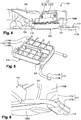
- FIG. 2 to 6 are shown a rear structure of a motor vehicle 101 according to a first embodiment of the invention.
- This structure 101 comprises a floor 109, itself formed by a rear zone 109A and a front zone 109C, the rear zone 109A being raised relative to the front zone 109C and forming a projection 109B with respect to said front zone 109C.
- This structure 101 also includes a lateral structural spar 105, commonly referred to as a sill, extending laterally from the floor 109 of the vehicle, and a rear structural section 107, commonly referred to as a spar, extending longitudinally and rearwardly. from the step of the floor 109B.
- a reinforcement 115 is fixed to the rear structural section 107 and to the floor 109. This reinforcement 115 is divided into three portions: a front portion 117, a rear portion 119 and an intermediate portion 121.
- the rear portion 119 of the reinforcement 115 s' extends longitudinally from the floor step 109B rearward.
- it comprises vertical walls forming cavities 119A providing a function of absorbing deformation in compression, of the “crashbox” type.
- the cavities 119A are supported by a metallic tubular structure of the reinforcement, itself fixed to the rear structure of the vehicle 101.
- An outer side edge 119B is positioned along the side structural spar 105, and an inner side edge 119C is positioned along. and at a distance from the rear structural section 107.
- the tubular structure forms the intermediate portion 121 which extends to the front of the rear portion 119 of the reinforcement 115 and vertically along the projection 109B.
- the tubular structure forms the front portion 117 of the reinforcement 115.
- the figures 7 to 9 also describe a rear structure of a motor vehicle 201 with a reinforcement 215 according to a second embodiment of the invention. These figures show the numbering of the figures 2 to 6 for identical or similar elements, the numbering being however incremented by 100. Reference is also made to the description of these elements in relation to the first embodiment. Specific numbers between 200 and 300 are used for items specific to this embodiment.
- This reinforcement 215 has most of the characteristics of the reinforcement 115 described in the first embodiment.
- a rear portion 219 has the same arrangement as the rear portion 119 of the reinforcement 115, it extends forward by an intermediate portion 221, which extends vertically to rest on a projection 209B of the floor 209.
- This intermediate portion 221 is reinforced by additional tubular reinforcements.
- the reinforcement 215 in this case is designed in one piece. Another feature of this reinforcement 215 is that it is preferably made from metallic materials.
- the rear portion 219 according to the second embodiment of the invention may also have additional reinforcements, in particular on the outer side edges 219B and inner side 219C.
- the two embodiments of the reinforcements can be coupled together, or mounted separately.
Landscapes
- Engineering & Computer Science (AREA)
- Chemical & Material Sciences (AREA)
- Combustion & Propulsion (AREA)
- Transportation (AREA)
- Mechanical Engineering (AREA)
- Body Structure For Vehicles (AREA)
Description
- L'invention a trait au domaine des véhicules automobiles, plus particulièrement à la structure arrière de véhicules automobiles.
- La
figure 1 est une vue latérale et intérieure d'une structure arrière d'un véhicule automobile 1 selon l'art antérieur. Cette structure comprend un plancher 9 qui forme un ressaut 9B par rapport à une zone avant 9C dudit plancher 9. Deux profilés structurels arrière 7 couramment appelé longeronnets s'étendent longitudinalement et vers l'arrière à partir du ressaut du plancher 9B et sont positionnés à l'intérieur des roues arrière 3. De nouveaux protocoles de choc arrière décalé concernant des collisions sur 70% de la partie arrière du véhicule sont actuellement mis en place. Ce type de choc montre une tendance du profilé structurel arrière 7 à se verticaliser (représenté schématiquement par les traits interrompus), entraînant l'apparition de deux rotules 11. Ces rotules 11 correspondent à des fractures du profilé structurel arrière 7, elles conduisent à une diminution de l'absorption des chocs par ledit profilé 7. Afin de renforcer la structure du véhicule lors d'un choc arrière, il est envisageable de modifier la structure du châssis, ce qui se traduit alors par de lourds investissements. - Le document de brevet publié
US 7,213,873 B2 décrit une structure avant de véhicule automobile comprenant deux dispositifs absorbeurs de chocs à l'avant du véhicule et un renforcement unifiant les deux absorbeurs et positionné à l'arrière du pare-chocs. Ce renforcement va améliorer l'absorption d'énergie par les dispositifs absorbeurs de chocs. - Le document de brevet publié
US 2007/0132223 A1 divulgue deux dispositifs absorbeurs de chocs qui sont positionnés à la suite des deux longerons, eux-mêmes positionnés latéralement au plancher. Ce document décrit également un dispositif absorbeur de chocs supplémentaire appelé « crash box » qui est retrouvé entre le premier dispositif absorbeur de chocs et les longerons. Ces structures n'ont en revanche aucun effet sur la verticalisation du profilé structurel arrière, il améliore l'absorption des chocs. Le documentFR2914616 Fig.1 ), ladite structure comprenant :- un plancher (Fig.1 pos.5,2,6) avec une zone arrière (idem.) destinée à recevoir une banquette arrière, ladite zone étant surélevée en formant un ressaut (Fig.3 ) par rapport à une zone dudit plancher adjacente à l'avant ;- deux profilés structurels arrière (Fig.1 pos.3,12) s'étendant longitudinalement vers l'arrière sous la zone arrière du plancher depuis le ressaut (Fig.1 ,4 ). - L'invention a pour objectif de pallier au moins un des inconvénients de l'état de la technique susmentionné. Plus particulièrement, l'invention a pour objectif de rendre la structure arrière d'un véhicule automobile davantage apte à absorber un choc arrière, notamment le choc arrière décalé avec recouvrement à 70%, et de limiter la verticalisation du profilé structurel arrière.
- L'invention a pour objet une structure arrière d'un véhicule automobile, ladite structure comprenant : un plancher avec une zone arrière destinée à recevoir une banquette arrière, ladite zone étant surélevée en formant un ressaut par rapport à une zone dudit plancher adjacente à l'avant ; deux profilés structurels arrière s'étendant longitudinalement vers l'arrière sous la zone arrière du plancher depuis le ressaut ; remarquable en ce que la structure comprend, en outre : deux renforts sur les deux profilés structurels, respectivement ; chacun desdits renforts étant fixé au profilé correspondant et au plancher, au niveau du ressaut, et configuré de manière à limiter une tendance dudit profilé à pivoter verticalement vers le haut en cas de choc à l'arrière.
- Le ressaut est une portion du plancher orientée généralement verticalement et couramment désignée « plancher à talon ».
- Selon un mode avantageux de l'invention, chacun des renforts comprend une portion arrière s'étendant longitudinalement sous le profilé correspondant et une portion avant s'étendant sous la zone adjacente du plancher.
- Selon un mode avantageux de l'invention, pour chacun des renforts, la portion avant comprend des pattes s'étendant longitudinalement depuis la portion arrière ; lesdites pattes comprenant, chacune, au moins un œillet de fixation notamment par vis.
- Selon un mode avantageux de l'invention, au moins une des pattes de chacun des renforts est fixé à un profilé longitudinal s'étendant sous le plancher.
- Selon un mode avantageux de l'invention, pour chacun des renforts, la portion arrière s'étend verticalement le long d'une face latérale du profilé correspondant et est fixée à ladite face.
- Selon un mode avantageux de l'invention, chacun des renforts comprend une portion intermédiaire, située entre les portions arrière et avant, s'étendant verticalement le long du ressaut de manière à pouvoir prendre appui sur ledit ressaut en cas de pivotement vertical du profilé correspondant lors du choc à l'arrière.
- Cette portion intermédiaire peut être consolidée par des renforcements tubulaires supplémentaires.
- Selon un mode avantageux de l'invention, pour chacun des renforts, la portion arrière comprend à un bord latéral extérieur, à une position arrière, au moins un œillet de fixation par vis à un longeron structurel latéral du plancher.
- Selon un mode avantageux de l'invention, pour chacun des renforts, la portion arrière comprend des parois verticales formant des cavités en contact avec le profilé correspondant et apte à se déformer en compression lors du pivotement vertical dudit profilé lors du choc à l'arrière.
- Les parois verticales ont préférentiellement une épaisseur comprise entre 1 et 3mm.
- Selon un mode avantageux de l'invention, chacun des renforts comprend une structure tubulaire métallique s'étendant sur les portions avant et arrière ; les cavités déformables, le cas échéant, étant rapportées sur ladite structure.
- Cette structure tubulaire métallique peut servir à fixer le renfort sur la structure arrière du véhicule, en particulier sur le longeron structurel latéral, sur le profilé longitudinal et le profilé structurel arrière. Dans ce cas, les cavités déformables sont préférentiellement fabriquées en matériau composite, tel que le BMC (acronyme de « Bulk Molding Compound »), et/ou en matériau SMC (acronyme de « Sheet Molding Compound »). La structure tubulaire est préférentiellement en acier, et d'un diamètre compris entre 30 et 45 mm, avec une épaisseur comprise entre 2 et 3,5mm.
- Selon un mode avantageux de l'invention, chacun des renforts est une pièce métallique de fonderie formant les portions avant ; arrière ; intermédiaire, le cas échéant ; et les cavités déformables, le cas échéant. Dans ce cas, la pièce métallique peut être réalisée en aluminium. Elle peut également présenter des renforcements supplémentaires notamment sur les bords latéraux externe et interne de la portion arrière. L'épaisseur des parois verticales est préférentiellement comprise entre 2 et 4 mm, et l'épaisseur de la portion arrière est comprise entre 4 et 6mm.
- Les mesures de l'invention sont intéressantes en ce qu'elles permettent de réaliser un renforcement la structure arrière d'un véhicule sans augmentation de poids substantielle. Enfin, elle empêche la verticalisation des profilés structurels arrière.
- D'autres caractéristiques et avantages de la présente invention seront mieux compris à l'aide de la description et des dessins parmi lesquels :
- La
figure 1 est une coupe latérale d'un véhicule automobile selon l'art antérieur et qui a été décrite précédemment ; - La
figure 2 est une vue de dessous de la structure d'un véhicule automobile, selon un premier mode de réalisation de l'invention ; - La
figure 3 est une vue de 3/4 et du dessous de la structure de lafigure 2 ; - La
figure 4 est une vue latérale de la structure desfigures 2 et 3 ; - La
figure 5 est une vue en perspective du renfort desfigures 2 à 4 ; - La
figure 6 est une vue de dessous de la structure desfigures 2 à 5 ; - La
figure 7 est une vue du dessous de la structure d'un véhicule automobile selon un deuxième mode de réalisation de l'invention ; - La
figure 8 est une vue de ¾ arrière de la structure de lafigure 7 ; - La
figure 9 représente le renfort de la structure desfigures 7 et 8 . - Sur les
figures 2 à 6 sont représentés une structure arrière d'un véhicule automobile 101 selon un premier mode de réalisation de l'invention. - Cette structure 101 comprend un plancher 109, lui-même constitué par une zone arrière 109A et une zone avant 109C, la zone arrière 109A étant surélevée par rapport à la zone avant 109C et formant un ressaut 109B par rapport à ladite zone avant 109C. Cette structure 101 comprend également un longeron structurel latéral 105, couramment appelé bas de caisse, s'étendant latéralement à partir du plancher 109 du véhicule, et un profilé structurel arrière 107, couramment appelé longeronnet, s'étendant longitudinalement et vers l'arrière à partir du ressaut du plancher 109B. Un renfort 115 est fixé sur le profilé structurel arrière 107 et sur le plancher 109. Ce renfort 115 est divisé en trois portions : une portion avant 117, une portion arrière 119 et une portion intermédiaire 121. La portion arrière 119 du renfort 115 s'étend longitudinalement à partir du ressaut du plancher 109B vers l'arrière. En l'occurrence, elle comprend des parois verticales formant des cavités 119A assurant une fonction d'absorption de déformation en compression, du type « crashbox ». Les cavités 119A sont supportées par une structure tubulaire métallique du renfort, elle-même fixée à la structure arrière du véhicule 101. Un bord latéral extérieur 119B est positionné le long du longeron structurel latéral 105, et un bord latéral intérieur 119C est positionné le long et à distance du profilé structurel arrière 107. La structure tubulaire forme la portion intermédiaire 121 qui s'étend à l'avant de la portion arrière 119 du renfort 115 et verticalement le long du ressaut 109B. Enfin, la structure tubulaire forme la portion avant 117 du renfort 115. De la portion arrière 119 partent deux pattes 117A, qui vont se fixer sur deux profilés longitudinaux 113 positionnés sous le plancher 109. La fixation se fait grâce à des œillets de fixation 117B, et préférentiellement par des vis. La fixation à l'avant sur ces profilés peut se faire soit sur les profilés 113 (comme montré en
figure 2 et 3 ), ou dans les profilés longitudinaux 113 (comme montré enfigure 6 ). - Les
figures 7 à 9 décrivent également une structure arrière d'un véhicule automobile 201 avec un renfort 215 selon un deuxième mode de réalisation de l'invention. Ces figures reprennent la numérotation desfigures 2 à 6 pour les éléments identiques ou similaires, la numération étant toutefois incrémentée de 100. Il est par ailleurs fait référence à la description de ces éléments en relation avec le premier mode de réalisation. Des numéros spécifiques compris entre 200 et 300 sont utilisés pour les éléments spécifiques à ce mode de réalisation. Ce renfort 215 présente la plupart des caractéristiques du renfort 115 décrit dans le premier mode de réalisation. - Une portion arrière 219 a la même disposition que la portion arrière 119 du renfort 115, elle se prolonge vers l'avant par une portion intermédiaire 221, qui s'étend verticalement pour prendre appui sur un ressaut 209B du plancher 209. Cette portion intermédiaire 221 est renforcée par des renforcements tubulaires supplémentaires. De la portion arrière 219 partent deux pattes 217A terminées par des œillets de fixation 217B et qui vont permettre de fixer le renfort 215 sur des profilés longitudinaux 213 positionnés sous le plancher 209 du véhicule. Le renfort 215 dans ce cas est conçu d'un seul tenant. Une autre particularité de ce renfort 215 est qu'il est préférentiellement réalisé dans des matériaux métalliques. La portion arrière 219 selon le deuxième mode de réalisation de l'invention peut également présenter des renforcements supplémentaires, notamment sur des bords latéraux externe 219B et interne 219C.
- Les deux modes de réalisation des renforts peuvent être couplés entre eux, ou montés séparément.
Claims (10)
- Structure arrière d'un véhicule automobile (101 ; 201), ladite structure comprenant :- un plancher (109 ; 209) avec une zone arrière (109A ; 209A) destinée à recevoir une banquette arrière, ladite zone étant surélevée en formant un ressaut (109B ; 209B) par rapport à une zone dudit plancher (109 ; 209) adjacente à l'avant ;- deux profilés structurels arrière (107 ; 207) s'étendant longitudinalement vers l'arrière sous la zone arrière du plancher (109A ; 209A) depuis le ressaut (109B ; 209B) ;caractérisée en ce que la structure (101 ; 201) comprend, en outre :- deux renforts (115 ; 215) sur les deux profilés structurels (107; 207), respectivement ; chacun desdits renforts (115 ; 215) étant fixé au profilé (107; 207) correspondant et au plancher (109; 209), au niveau du ressaut (109B ; 209B), et configuré de manière à limiter une tendance dudit profilé (107 ; 207) à pivoter verticalement vers le haut en cas de choc à l'arrière.
- Structure arrière (101 ; 201) selon la revendication 1, caractérisée en ce que chacun des renforts (115 ; 215) comprend une portion arrière (119 ; 219) s'étendant longitudinalement sous le profilé (107 ; 207) correspondant et une portion avant (117; 217) s'étendant sous la zone adjacente du plancher (109 ; 209).
- Structure arrière (101 ; 201) selon la revendication 2, caractérisée en ce que pour chacun des renforts (115 ; 215), la portion avant (117 ; 217) comprend des pattes s'étendant longitudinalement depuis la portion arrière (119 ; 219) ; lesdites pattes (117A ; 217A) comprenant, chacune, au moins un œillet de fixation (117B ; 217B) par vis.
- Structure arrière (101 ; 201) selon la revendication 3, caractérisée en ce qu'au moins une des pattes (117A ; 217A) de chacun des renforts (115 ; 215) est fixé à un profilé longitudinal (113 ; 213) s'étendant sous le plancher (109 ; 209).
- Structure arrière (101 ; 201) selon l'une quelconque des revendications 2 à 4, caractérisée en ce que pour chacun des renforts (115 ; 215), la portion arrière (119 ; 219) s'étend verticalement le long d'une face latérale du profilé (107 ; 207) correspondant et est fixée à ladite face.
- Structure arrière (101 ; 201) selon l'une quelconque des revendications 2 à 5, caractérisée en ce que chacun des renforts (115 ; 215) comprend une portion intermédiaire (121 ; 221), située entre les portions arrière (119 ; 219) et avant (117 ; 217), s'étendant verticalement le long du ressaut (109B ; 209B) de manière à pouvoir prendre appui sur ledit ressaut (109B ; 209B) en cas de pivotement vertical du profilé (107; 207) correspondant lors du choc à l'arrière.
- Structure arrière (101 ; 201) selon l'une quelconque des revendications 2 à 6, caractérisée en ce que pour chacun des renforts (115 ; 215), la portion arrière (119 ; 219) comprend à un bord latéral extérieur (119B ; 219B), à une position arrière, au moins un œillet de fixation (117B ; 217B) par vis à un longeron structurel latéral (105 ; 205) du plancher (109 ; 209).
- Structure arrière (101 ; 201) selon l'une quelconque des revendications 2 à 7, caractérisée en ce que pour chacun des renforts (115 ; 215), la portion arrière (119 ; 219) comprend des parois verticales formant des cavités (119A ; 219A) en contact avec le profilé (107 ; 207) correspondant et apte à se déformer en compression lors du pivotement vertical dudit profilé (107 ; 207) lors du choc à l'arrière.
- Structure arrière (101) selon l'une quelconque des revendications 1 à 8, caractérisée en ce que chacun des renforts (115) comprend une structure tubulaire métallique s'étendant sur les portions avant (117) et arrière (119) ; les cavités déformables (119A), le cas échéant, étant rapportées sur ladite structure.
- Structure arrière (201) selon l'une quelconque des revendications 1 à 8, caractérisée en ce que chacun des renforts (215) est une pièce métallique de fonderie formant les portions avant (217) ; arrière (219) ; intermédiaire (221), le cas échéant ; et les cavités déformables (219A), le cas échéant.
Applications Claiming Priority (2)
| Application Number | Priority Date | Filing Date | Title |
|---|---|---|---|
| FR1662688A FR3060507B1 (fr) | 2016-12-16 | 2016-12-16 | Structure arriere de vehicule automobile comprenant un renfort pour les collisions a l'arriere |
| PCT/FR2017/053097 WO2018109293A1 (fr) | 2016-12-16 | 2017-11-13 | Structure arriere de vehicule automobile comprenant un renfort pour les collisions a l'arriere |
Publications (2)
| Publication Number | Publication Date |
|---|---|
| EP3554924A1 EP3554924A1 (fr) | 2019-10-23 |
| EP3554924B1 true EP3554924B1 (fr) | 2021-02-24 |
Family
ID=58347590
Family Applications (1)
| Application Number | Title | Priority Date | Filing Date |
|---|---|---|---|
| EP17808971.0A Active EP3554924B1 (fr) | 2016-12-16 | 2017-11-13 | Structure arrière de véhicule automobile comprenant un renfort pour les collisions à l'arrière |
Country Status (5)
| Country | Link |
|---|---|
| US (1) | US10737727B2 (fr) |
| EP (1) | EP3554924B1 (fr) |
| CN (1) | CN110087975B (fr) |
| FR (1) | FR3060507B1 (fr) |
| WO (1) | WO2018109293A1 (fr) |
Families Citing this family (1)
| Publication number | Priority date | Publication date | Assignee | Title |
|---|---|---|---|---|
| FR3101600B1 (fr) * | 2019-10-04 | 2021-08-27 | Psa Automobiles Sa | Absorbeur de choc latéral pour véhicule automobile |
Family Cites Families (13)
| Publication number | Priority date | Publication date | Assignee | Title |
|---|---|---|---|---|
| GB2306922B (en) * | 1994-08-31 | 1997-11-12 | Fuji Heavy Ind Ltd | Vehicle body structure |
| DE19703951C2 (de) * | 1996-02-22 | 2000-05-18 | Daihatsu Motor Co Ltd | Vorderteilkonstruktion einer Fahrzeugkarosserie |
| DE10321573B4 (de) | 2003-05-14 | 2008-09-25 | Daimler Ag | Crashstruktur für eine Kraftwagen-Rohbaustruktur |
| JP4195839B2 (ja) | 2003-06-30 | 2008-12-17 | タカタ株式会社 | エアバッグカバー、エアバッグモジュール |
| US7213873B2 (en) | 2004-03-25 | 2007-05-08 | Mazda Motor Corporation | Vehicle front-part structure |
| US7364225B2 (en) * | 2005-12-15 | 2008-04-29 | Mazda Motor Corporation | Vehicle body structure |
| FR2914616B1 (fr) * | 2007-04-04 | 2009-05-29 | Renault Sas | Soubassement de vehicule automobile |
| JP5417878B2 (ja) * | 2008-05-09 | 2014-02-19 | 日産自動車株式会社 | 自動車車体の後部構造 |
| DE102010019992A1 (de) * | 2010-05-10 | 2011-11-10 | Volkswagen Ag | Karosseriestruktur, insbesondere Bodenstruktur, für ein Kraftfahrzeug |
| JP5375886B2 (ja) * | 2011-07-26 | 2013-12-25 | トヨタ自動車株式会社 | 自動車の電池保護構造 |
| JP6016075B2 (ja) * | 2012-06-06 | 2016-10-26 | スズキ株式会社 | 車体中央部のフロア構造 |
| WO2014034309A1 (fr) * | 2012-08-31 | 2014-03-06 | 本田技研工業株式会社 | Structure arrière de carrosserie de véhicule |
| DE102013114311A1 (de) * | 2013-12-18 | 2015-06-18 | Dr. Ing. H.C. F. Porsche Aktiengesellschaft | Kraftfahrzeugheck |
-
2016
- 2016-12-16 FR FR1662688A patent/FR3060507B1/fr not_active Expired - Fee Related
-
2017
- 2017-11-13 CN CN201780078159.7A patent/CN110087975B/zh active Active
- 2017-11-13 EP EP17808971.0A patent/EP3554924B1/fr active Active
- 2017-11-13 US US16/464,783 patent/US10737727B2/en active Active
- 2017-11-13 WO PCT/FR2017/053097 patent/WO2018109293A1/fr not_active Ceased
Non-Patent Citations (1)
| Title |
|---|
| None * |
Also Published As
| Publication number | Publication date |
|---|---|
| EP3554924A1 (fr) | 2019-10-23 |
| CN110087975B (zh) | 2022-05-17 |
| US10737727B2 (en) | 2020-08-11 |
| CN110087975A (zh) | 2019-08-02 |
| US20190337569A1 (en) | 2019-11-07 |
| FR3060507A1 (fr) | 2018-06-22 |
| WO2018109293A1 (fr) | 2018-06-21 |
| FR3060507B1 (fr) | 2019-01-25 |
Similar Documents
| Publication | Publication Date | Title |
|---|---|---|
| EP2855242B1 (fr) | Structure de vehicule avec support d'aile a deformation controlee en cas d'impact | |
| WO2018078226A1 (fr) | Renfort de la structure avant d'un vehicule automobile pour choc frontal a faible recouvrement | |
| EP2282915A1 (fr) | Dispositif d'absorption de choc et face avant comportant un tel dispositif | |
| EP2744698B1 (fr) | Caisse de vehicule automobile comprenant un dispositif de raidissement | |
| EP3554924B1 (fr) | Structure arrière de véhicule automobile comprenant un renfort pour les collisions à l'arrière | |
| EP3126209B1 (fr) | Structure de vehicule automobile renforcee | |
| WO2022258898A1 (fr) | Élément absorbeur de chocs pour véhicule automobile | |
| FR3022520A1 (fr) | Plancher de vehicule automobile avec podium de renfort composite | |
| EP3787956B1 (fr) | Structure de vehicule avec longeron renforce | |
| EP3386845A1 (fr) | Elément de carrosserie pour véhicule automobile et procédé de fabrication correspondant | |
| FR3121636A1 (fr) | Porte de véhicule automobile renforcée pour choc latéral | |
| FR3111615A1 (fr) | Renfort de liaison entre un pied avant de véhicule automobile et une ligne de brancard dudit véhicule automobile | |
| EP2234865A1 (fr) | Structure de vehicule automobile | |
| FR3082819A1 (fr) | Caisse de vehicule automobile, pourvue d'un support pour un enrouleur de ceinture de securite arriere qui integre une aile de renfort de la caisse | |
| FR3164681A1 (fr) | Berceau avant de véhicule automobile | |
| FR3138644A1 (fr) | Structure de véhicule automobile avec plancher de chargement | |
| FR3141430A1 (fr) | Ensemble de renfort avant pour véhicule automobile | |
| FR3124153A1 (fr) | Renfort destiné à être logé dans un longeron de véhicule automobile | |
| FR3136735A1 (fr) | longeronnet avec amorce de pliage pour véhicule automobile | |
| FR2836885A1 (fr) | Element de structure et structure arriere d'un vehicule automobile, procede de fabrication d'une telle structure | |
| WO2020208315A1 (fr) | Renfort de longeron interieur | |
| WO2019239023A1 (fr) | Renfort de montant arriere de vehicule automobile. | |
| FR2968629A1 (fr) | Dispositif de guidage de la compression d'un longeron de brancard d'un vehicule. | |
| FR3024846A1 (fr) | Structure de porte de vehicule automobile a caisson structurel et cadre de porte delimitant un corps creux formant renfort de bandeau de porte | |
| FR3015417A1 (fr) | Structure de soubassement d'un vehicule automobile comportant un element fusible |
Legal Events
| Date | Code | Title | Description |
|---|---|---|---|
| STAA | Information on the status of an ep patent application or granted ep patent |
Free format text: STATUS: UNKNOWN |
|
| STAA | Information on the status of an ep patent application or granted ep patent |
Free format text: STATUS: THE INTERNATIONAL PUBLICATION HAS BEEN MADE |
|
| PUAI | Public reference made under article 153(3) epc to a published international application that has entered the european phase |
Free format text: ORIGINAL CODE: 0009012 |
|
| STAA | Information on the status of an ep patent application or granted ep patent |
Free format text: STATUS: REQUEST FOR EXAMINATION WAS MADE |
|
| 17P | Request for examination filed |
Effective date: 20190503 |
|
| AK | Designated contracting states |
Kind code of ref document: A1 Designated state(s): AL AT BE BG CH CY CZ DE DK EE ES FI FR GB GR HR HU IE IS IT LI LT LU LV MC MK MT NL NO PL PT RO RS SE SI SK SM TR |
|
| AX | Request for extension of the european patent |
Extension state: BA ME |
|
| DAV | Request for validation of the european patent (deleted) | ||
| DAX | Request for extension of the european patent (deleted) | ||
| GRAP | Despatch of communication of intention to grant a patent |
Free format text: ORIGINAL CODE: EPIDOSNIGR1 |
|
| STAA | Information on the status of an ep patent application or granted ep patent |
Free format text: STATUS: GRANT OF PATENT IS INTENDED |
|
| INTG | Intention to grant announced |
Effective date: 20200928 |
|
| RAP1 | Party data changed (applicant data changed or rights of an application transferred) |
Owner name: PSA AUTOMOBILES SA |
|
| GRAS | Grant fee paid |
Free format text: ORIGINAL CODE: EPIDOSNIGR3 |
|
| GRAA | (expected) grant |
Free format text: ORIGINAL CODE: 0009210 |
|
| STAA | Information on the status of an ep patent application or granted ep patent |
Free format text: STATUS: THE PATENT HAS BEEN GRANTED |
|
| AK | Designated contracting states |
Kind code of ref document: B1 Designated state(s): AL AT BE BG CH CY CZ DE DK EE ES FI FR GB GR HR HU IE IS IT LI LT LU LV MC MK MT NL NO PL PT RO RS SE SI SK SM TR |
|
| REG | Reference to a national code |
Ref country code: CH Ref legal event code: EP |
|
| REG | Reference to a national code |
Ref country code: DE Ref legal event code: R084 Ref document number: 602017033432 Country of ref document: DE |
|
| REG | Reference to a national code |
Ref country code: AT Ref legal event code: REF Ref document number: 1364101 Country of ref document: AT Kind code of ref document: T Effective date: 20210315 |
|
| REG | Reference to a national code |
Ref country code: IE Ref legal event code: FG4D Free format text: LANGUAGE OF EP DOCUMENT: FRENCH |
|
| REG | Reference to a national code |
Ref country code: DE Ref legal event code: R096 Ref document number: 602017033432 Country of ref document: DE |
|
| REG | Reference to a national code |
Ref country code: LT Ref legal event code: MG9D |
|
| REG | Reference to a national code |
Ref country code: NL Ref legal event code: MP Effective date: 20210224 |
|
| PG25 | Lapsed in a contracting state [announced via postgrant information from national office to epo] |
Ref country code: LT Free format text: LAPSE BECAUSE OF FAILURE TO SUBMIT A TRANSLATION OF THE DESCRIPTION OR TO PAY THE FEE WITHIN THE PRESCRIBED TIME-LIMIT Effective date: 20210224 Ref country code: BG Free format text: LAPSE BECAUSE OF FAILURE TO SUBMIT A TRANSLATION OF THE DESCRIPTION OR TO PAY THE FEE WITHIN THE PRESCRIBED TIME-LIMIT Effective date: 20210524 Ref country code: HR Free format text: LAPSE BECAUSE OF FAILURE TO SUBMIT A TRANSLATION OF THE DESCRIPTION OR TO PAY THE FEE WITHIN THE PRESCRIBED TIME-LIMIT Effective date: 20210224 Ref country code: GR Free format text: LAPSE BECAUSE OF FAILURE TO SUBMIT A TRANSLATION OF THE DESCRIPTION OR TO PAY THE FEE WITHIN THE PRESCRIBED TIME-LIMIT Effective date: 20210525 Ref country code: FI Free format text: LAPSE BECAUSE OF FAILURE TO SUBMIT A TRANSLATION OF THE DESCRIPTION OR TO PAY THE FEE WITHIN THE PRESCRIBED TIME-LIMIT Effective date: 20210224 Ref country code: NO Free format text: LAPSE BECAUSE OF FAILURE TO SUBMIT A TRANSLATION OF THE DESCRIPTION OR TO PAY THE FEE WITHIN THE PRESCRIBED TIME-LIMIT Effective date: 20210524 Ref country code: PT Free format text: LAPSE BECAUSE OF FAILURE TO SUBMIT A TRANSLATION OF THE DESCRIPTION OR TO PAY THE FEE WITHIN THE PRESCRIBED TIME-LIMIT Effective date: 20210624 |
|
| REG | Reference to a national code |
Ref country code: AT Ref legal event code: MK05 Ref document number: 1364101 Country of ref document: AT Kind code of ref document: T Effective date: 20210224 |
|
| PG25 | Lapsed in a contracting state [announced via postgrant information from national office to epo] |
Ref country code: RS Free format text: LAPSE BECAUSE OF FAILURE TO SUBMIT A TRANSLATION OF THE DESCRIPTION OR TO PAY THE FEE WITHIN THE PRESCRIBED TIME-LIMIT Effective date: 20210224 Ref country code: LV Free format text: LAPSE BECAUSE OF FAILURE TO SUBMIT A TRANSLATION OF THE DESCRIPTION OR TO PAY THE FEE WITHIN THE PRESCRIBED TIME-LIMIT Effective date: 20210224 Ref country code: NL Free format text: LAPSE BECAUSE OF FAILURE TO SUBMIT A TRANSLATION OF THE DESCRIPTION OR TO PAY THE FEE WITHIN THE PRESCRIBED TIME-LIMIT Effective date: 20210224 Ref country code: PL Free format text: LAPSE BECAUSE OF FAILURE TO SUBMIT A TRANSLATION OF THE DESCRIPTION OR TO PAY THE FEE WITHIN THE PRESCRIBED TIME-LIMIT Effective date: 20210224 Ref country code: SE Free format text: LAPSE BECAUSE OF FAILURE TO SUBMIT A TRANSLATION OF THE DESCRIPTION OR TO PAY THE FEE WITHIN THE PRESCRIBED TIME-LIMIT Effective date: 20210224 |
|
| PG25 | Lapsed in a contracting state [announced via postgrant information from national office to epo] |
Ref country code: IS Free format text: LAPSE BECAUSE OF FAILURE TO SUBMIT A TRANSLATION OF THE DESCRIPTION OR TO PAY THE FEE WITHIN THE PRESCRIBED TIME-LIMIT Effective date: 20210624 |
|
| PG25 | Lapsed in a contracting state [announced via postgrant information from national office to epo] |
Ref country code: CZ Free format text: LAPSE BECAUSE OF FAILURE TO SUBMIT A TRANSLATION OF THE DESCRIPTION OR TO PAY THE FEE WITHIN THE PRESCRIBED TIME-LIMIT Effective date: 20210224 Ref country code: EE Free format text: LAPSE BECAUSE OF FAILURE TO SUBMIT A TRANSLATION OF THE DESCRIPTION OR TO PAY THE FEE WITHIN THE PRESCRIBED TIME-LIMIT Effective date: 20210224 Ref country code: AT Free format text: LAPSE BECAUSE OF FAILURE TO SUBMIT A TRANSLATION OF THE DESCRIPTION OR TO PAY THE FEE WITHIN THE PRESCRIBED TIME-LIMIT Effective date: 20210224 Ref country code: SM Free format text: LAPSE BECAUSE OF FAILURE TO SUBMIT A TRANSLATION OF THE DESCRIPTION OR TO PAY THE FEE WITHIN THE PRESCRIBED TIME-LIMIT Effective date: 20210224 |
|
| REG | Reference to a national code |
Ref country code: DE Ref legal event code: R097 Ref document number: 602017033432 Country of ref document: DE |
|
| PG25 | Lapsed in a contracting state [announced via postgrant information from national office to epo] |
Ref country code: RO Free format text: LAPSE BECAUSE OF FAILURE TO SUBMIT A TRANSLATION OF THE DESCRIPTION OR TO PAY THE FEE WITHIN THE PRESCRIBED TIME-LIMIT Effective date: 20210224 Ref country code: DK Free format text: LAPSE BECAUSE OF FAILURE TO SUBMIT A TRANSLATION OF THE DESCRIPTION OR TO PAY THE FEE WITHIN THE PRESCRIBED TIME-LIMIT Effective date: 20210224 Ref country code: SK Free format text: LAPSE BECAUSE OF FAILURE TO SUBMIT A TRANSLATION OF THE DESCRIPTION OR TO PAY THE FEE WITHIN THE PRESCRIBED TIME-LIMIT Effective date: 20210224 |
|
| REG | Reference to a national code |
Ref country code: GB Ref legal event code: 746 Effective date: 20210524 |
|
| PLBE | No opposition filed within time limit |
Free format text: ORIGINAL CODE: 0009261 |
|
| STAA | Information on the status of an ep patent application or granted ep patent |
Free format text: STATUS: NO OPPOSITION FILED WITHIN TIME LIMIT |
|
| PG25 | Lapsed in a contracting state [announced via postgrant information from national office to epo] |
Ref country code: ES Free format text: LAPSE BECAUSE OF FAILURE TO SUBMIT A TRANSLATION OF THE DESCRIPTION OR TO PAY THE FEE WITHIN THE PRESCRIBED TIME-LIMIT Effective date: 20210224 Ref country code: AL Free format text: LAPSE BECAUSE OF FAILURE TO SUBMIT A TRANSLATION OF THE DESCRIPTION OR TO PAY THE FEE WITHIN THE PRESCRIBED TIME-LIMIT Effective date: 20210224 |
|
| 26N | No opposition filed |
Effective date: 20211125 |
|
| PG25 | Lapsed in a contracting state [announced via postgrant information from national office to epo] |
Ref country code: SI Free format text: LAPSE BECAUSE OF FAILURE TO SUBMIT A TRANSLATION OF THE DESCRIPTION OR TO PAY THE FEE WITHIN THE PRESCRIBED TIME-LIMIT Effective date: 20210224 |
|
| PG25 | Lapsed in a contracting state [announced via postgrant information from national office to epo] |
Ref country code: IT Free format text: LAPSE BECAUSE OF FAILURE TO SUBMIT A TRANSLATION OF THE DESCRIPTION OR TO PAY THE FEE WITHIN THE PRESCRIBED TIME-LIMIT Effective date: 20210224 |
|
| PG25 | Lapsed in a contracting state [announced via postgrant information from national office to epo] |
Ref country code: IS Free format text: LAPSE BECAUSE OF FAILURE TO SUBMIT A TRANSLATION OF THE DESCRIPTION OR TO PAY THE FEE WITHIN THE PRESCRIBED TIME-LIMIT Effective date: 20210624 |
|
| PG25 | Lapsed in a contracting state [announced via postgrant information from national office to epo] |
Ref country code: MC Free format text: LAPSE BECAUSE OF FAILURE TO SUBMIT A TRANSLATION OF THE DESCRIPTION OR TO PAY THE FEE WITHIN THE PRESCRIBED TIME-LIMIT Effective date: 20210224 |
|
| REG | Reference to a national code |
Ref country code: CH Ref legal event code: PL |
|
| PG25 | Lapsed in a contracting state [announced via postgrant information from national office to epo] |
Ref country code: LU Free format text: LAPSE BECAUSE OF NON-PAYMENT OF DUE FEES Effective date: 20211113 Ref country code: BE Free format text: LAPSE BECAUSE OF NON-PAYMENT OF DUE FEES Effective date: 20211130 |
|
| REG | Reference to a national code |
Ref country code: BE Ref legal event code: MM Effective date: 20211130 |
|
| PG25 | Lapsed in a contracting state [announced via postgrant information from national office to epo] |
Ref country code: IE Free format text: LAPSE BECAUSE OF NON-PAYMENT OF DUE FEES Effective date: 20211113 |
|
| PG25 | Lapsed in a contracting state [announced via postgrant information from national office to epo] |
Ref country code: CY Free format text: LAPSE BECAUSE OF FAILURE TO SUBMIT A TRANSLATION OF THE DESCRIPTION OR TO PAY THE FEE WITHIN THE PRESCRIBED TIME-LIMIT Effective date: 20210224 |
|
| PG25 | Lapsed in a contracting state [announced via postgrant information from national office to epo] |
Ref country code: LI Free format text: LAPSE BECAUSE OF NON-PAYMENT OF DUE FEES Effective date: 20220630 Ref country code: HU Free format text: LAPSE BECAUSE OF FAILURE TO SUBMIT A TRANSLATION OF THE DESCRIPTION OR TO PAY THE FEE WITHIN THE PRESCRIBED TIME-LIMIT; INVALID AB INITIO Effective date: 20171113 Ref country code: CH Free format text: LAPSE BECAUSE OF NON-PAYMENT OF DUE FEES Effective date: 20220630 |
|
| REG | Reference to a national code |
Ref country code: DE Ref legal event code: R081 Ref document number: 602017033432 Country of ref document: DE Owner name: STELLANTIS AUTO SAS, FR Free format text: FORMER OWNER: PSA AUTOMOBILES SA, POISSY, FR |
|
| PG25 | Lapsed in a contracting state [announced via postgrant information from national office to epo] |
Ref country code: MK Free format text: LAPSE BECAUSE OF FAILURE TO SUBMIT A TRANSLATION OF THE DESCRIPTION OR TO PAY THE FEE WITHIN THE PRESCRIBED TIME-LIMIT Effective date: 20210224 |
|
| PG25 | Lapsed in a contracting state [announced via postgrant information from national office to epo] |
Ref country code: MT Free format text: LAPSE BECAUSE OF FAILURE TO SUBMIT A TRANSLATION OF THE DESCRIPTION OR TO PAY THE FEE WITHIN THE PRESCRIBED TIME-LIMIT Effective date: 20210224 |
|
| PG25 | Lapsed in a contracting state [announced via postgrant information from national office to epo] |
Ref country code: TR Free format text: LAPSE BECAUSE OF FAILURE TO SUBMIT A TRANSLATION OF THE DESCRIPTION OR TO PAY THE FEE WITHIN THE PRESCRIBED TIME-LIMIT Effective date: 20210224 |
|
| PGFP | Annual fee paid to national office [announced via postgrant information from national office to epo] |
Ref country code: DE Payment date: 20251022 Year of fee payment: 9 |
|
| PGFP | Annual fee paid to national office [announced via postgrant information from national office to epo] |
Ref country code: GB Payment date: 20251023 Year of fee payment: 9 |
|
| PGFP | Annual fee paid to national office [announced via postgrant information from national office to epo] |
Ref country code: FR Payment date: 20251022 Year of fee payment: 9 |