EP3554760B1 - Verfahren und vorrichtung zum formen von werkstücken - Google Patents
Verfahren und vorrichtung zum formen von werkstücken Download PDFInfo
- Publication number
- EP3554760B1 EP3554760B1 EP17832318.4A EP17832318A EP3554760B1 EP 3554760 B1 EP3554760 B1 EP 3554760B1 EP 17832318 A EP17832318 A EP 17832318A EP 3554760 B1 EP3554760 B1 EP 3554760B1
- Authority
- EP
- European Patent Office
- Prior art keywords
- tool
- shaping
- workpiece
- amount
- offset
- Prior art date
- Legal status (The legal status is an assumption and is not a legal conclusion. Google has not performed a legal analysis and makes no representation as to the accuracy of the status listed.)
- Active
Links
Images


Classifications
-
- B—PERFORMING OPERATIONS; TRANSPORTING
- B24—GRINDING; POLISHING
- B24B—MACHINES, DEVICES, OR PROCESSES FOR GRINDING OR POLISHING; DRESSING OR CONDITIONING OF ABRADING SURFACES; FEEDING OF GRINDING, POLISHING, OR LAPPING AGENTS
- B24B53/00—Devices or means for dressing or conditioning abrasive surfaces
- B24B53/017—Devices or means for dressing, cleaning or otherwise conditioning lapping tools
-
- B—PERFORMING OPERATIONS; TRANSPORTING
- B24—GRINDING; POLISHING
- B24B—MACHINES, DEVICES, OR PROCESSES FOR GRINDING OR POLISHING; DRESSING OR CONDITIONING OF ABRADING SURFACES; FEEDING OF GRINDING, POLISHING, OR LAPPING AGENTS
- B24B49/00—Measuring or gauging equipment for controlling the feed movement of the grinding tool or work; Arrangements of indicating or measuring equipment, e.g. for indicating the start of the grinding operation
- B24B49/02—Measuring or gauging equipment for controlling the feed movement of the grinding tool or work; Arrangements of indicating or measuring equipment, e.g. for indicating the start of the grinding operation according to the instantaneous size and required size of the workpiece acted upon, the measuring or gauging being continuous or intermittent
-
- B—PERFORMING OPERATIONS; TRANSPORTING
- B24—GRINDING; POLISHING
- B24B—MACHINES, DEVICES, OR PROCESSES FOR GRINDING OR POLISHING; DRESSING OR CONDITIONING OF ABRADING SURFACES; FEEDING OF GRINDING, POLISHING, OR LAPPING AGENTS
- B24B51/00—Arrangements for automatic control of a series of individual steps in grinding a workpiece
-
- B—PERFORMING OPERATIONS; TRANSPORTING
- B24—GRINDING; POLISHING
- B24B—MACHINES, DEVICES, OR PROCESSES FOR GRINDING OR POLISHING; DRESSING OR CONDITIONING OF ABRADING SURFACES; FEEDING OF GRINDING, POLISHING, OR LAPPING AGENTS
- B24B53/00—Devices or means for dressing or conditioning abrasive surfaces
- B24B53/06—Devices or means for dressing or conditioning abrasive surfaces of profiled abrasive wheels
-
- B—PERFORMING OPERATIONS; TRANSPORTING
- B24—GRINDING; POLISHING
- B24B—MACHINES, DEVICES, OR PROCESSES FOR GRINDING OR POLISHING; DRESSING OR CONDITIONING OF ABRADING SURFACES; FEEDING OF GRINDING, POLISHING, OR LAPPING AGENTS
- B24B13/00—Machines or devices designed for grinding or polishing optical surfaces on lenses or surfaces of similar shape on other work; Accessories therefor
- B24B13/01—Specific tools, e.g. bowl-like; Production, dressing or fastening of these tools
- B24B13/012—Specific tools, e.g. bowl-like; Production, dressing or fastening of these tools conformable in shape to the optical surface, e.g. by fluid pressure acting on an elastic membrane
-
- B—PERFORMING OPERATIONS; TRANSPORTING
- B24—GRINDING; POLISHING
- B24B—MACHINES, DEVICES, OR PROCESSES FOR GRINDING OR POLISHING; DRESSING OR CONDITIONING OF ABRADING SURFACES; FEEDING OF GRINDING, POLISHING, OR LAPPING AGENTS
- B24B49/00—Measuring or gauging equipment for controlling the feed movement of the grinding tool or work; Arrangements of indicating or measuring equipment, e.g. for indicating the start of the grinding operation
- B24B49/12—Measuring or gauging equipment for controlling the feed movement of the grinding tool or work; Arrangements of indicating or measuring equipment, e.g. for indicating the start of the grinding operation involving optical means
-
- B—PERFORMING OPERATIONS; TRANSPORTING
- B24—GRINDING; POLISHING
- B24B—MACHINES, DEVICES, OR PROCESSES FOR GRINDING OR POLISHING; DRESSING OR CONDITIONING OF ABRADING SURFACES; FEEDING OF GRINDING, POLISHING, OR LAPPING AGENTS
- B24B49/00—Measuring or gauging equipment for controlling the feed movement of the grinding tool or work; Arrangements of indicating or measuring equipment, e.g. for indicating the start of the grinding operation
- B24B49/18—Measuring or gauging equipment for controlling the feed movement of the grinding tool or work; Arrangements of indicating or measuring equipment, e.g. for indicating the start of the grinding operation taking regard of the presence of dressing tools
- B24B49/183—Wear compensation without the presence of dressing tools
-
- B—PERFORMING OPERATIONS; TRANSPORTING
- B24—GRINDING; POLISHING
- B24B—MACHINES, DEVICES, OR PROCESSES FOR GRINDING OR POLISHING; DRESSING OR CONDITIONING OF ABRADING SURFACES; FEEDING OF GRINDING, POLISHING, OR LAPPING AGENTS
- B24B53/00—Devices or means for dressing or conditioning abrasive surfaces
- B24B53/02—Devices or means for dressing or conditioning abrasive surfaces of plane surfaces on abrasive tools
-
- B—PERFORMING OPERATIONS; TRANSPORTING
- B24—GRINDING; POLISHING
- B24B—MACHINES, DEVICES, OR PROCESSES FOR GRINDING OR POLISHING; DRESSING OR CONDITIONING OF ABRADING SURFACES; FEEDING OF GRINDING, POLISHING, OR LAPPING AGENTS
- B24B53/00—Devices or means for dressing or conditioning abrasive surfaces
- B24B53/10—Devices or means for dressing or conditioning abrasive surfaces of travelling flexible backings coated with abrasives; Cleaning of abrasive belts
-
- B—PERFORMING OPERATIONS; TRANSPORTING
- B24—GRINDING; POLISHING
- B24D—TOOLS FOR GRINDING, BUFFING OR SHARPENING
- B24D13/00—Wheels having flexibly-acting working parts, e.g. buffing wheels; Mountings therefor
- B24D13/14—Wheels having flexibly-acting working parts, e.g. buffing wheels; Mountings therefor acting by the front face
- B24D13/142—Wheels of special form
-
- B—PERFORMING OPERATIONS; TRANSPORTING
- B24—GRINDING; POLISHING
- B24D—TOOLS FOR GRINDING, BUFFING OR SHARPENING
- B24D18/00—Manufacture of grinding tools or other grinding devices, e.g. wheels, not otherwise provided for
- B24D18/0009—Manufacture of grinding tools or other grinding devices, e.g. wheels, not otherwise provided for using moulds or presses
-
- B—PERFORMING OPERATIONS; TRANSPORTING
- B24—GRINDING; POLISHING
- B24D—TOOLS FOR GRINDING, BUFFING OR SHARPENING
- B24D2203/00—Tool surfaces formed with a pattern
-
- B—PERFORMING OPERATIONS; TRANSPORTING
- B24—GRINDING; POLISHING
- B24D—TOOLS FOR GRINDING, BUFFING OR SHARPENING
- B24D3/00—Physical features of abrasive bodies, or sheets, e.g. abrasive surfaces of special nature; Abrasive bodies or sheets characterised by their constituents
- B24D3/02—Physical features of abrasive bodies, or sheets, e.g. abrasive surfaces of special nature; Abrasive bodies or sheets characterised by their constituents the constituent being used as bonding agent
- B24D3/20—Physical features of abrasive bodies, or sheets, e.g. abrasive surfaces of special nature; Abrasive bodies or sheets characterised by their constituents the constituent being used as bonding agent and being essentially organic
- B24D3/28—Resins or natural or synthetic macromolecular compounds
Definitions
- the present invention relates to methods and apparatus for shaping workpieces, and is particularly concerned with shaping workpieces using tools which have a flexible working surface and are pressed against a workpiece to form a tool footprint by deforming the surface of the tool against the workpiece, and are rotated about an axis inclined to the workpiece surface so that the working surface of the tool within the tool footprint is moving relative to the workpiece surface.
- the tool footprint is moved over the workpiece surface by relative movement of the tool and the workpiece, so that the tool footprint reaches all parts of the surface to be worked.
- an abrasive working surface of the tool removes material from the workpiece to produce the required workpiece shape and finish.
- EP-A-0913229 describes a controller of a machine having an input means for inputting machining shape data concerning the final shape of a work and work data concerning the material and shape of the work before being machined, a data storing means in which machine data representing the machine specifications of the machine which machines the work and/or tool data on tools that the machine has, are stored, and a tool path determining means which generates a tool path along which the work is machined in accordance with the data inputted through the input means and the data stored in the data storing means, and which determines the machining conditions for the machining of the work such as the rotational speed of the main shaft and the feeding speed of the machine.
- the invention provides a method as defined in claim 1, an apparatus as defined in claim 8 and a system as defined in claim 11.
- the shaping tool comprises a flexible tool surface on which are arrayed a number of substantially rigid pellets, into which abrasive particles are embedded.
- this specification describes a method of determining tool control parameters which, when applied in a shaping process, ensure that the shaping process is able to remove material from the workpiece at the largest possible rates, while doing so under ductile cutting conditions which result in reduced sub-surface damage and improved surface finish quality.
- Also described in this specification is a system in which data representing the surface form of the workpiece is analysed in order either to select a tool able to perform the required shaping and/or finishing operation from a range of standard spherical tools, or to determine the required geometry of a non-standard tool to perform the required shaping and/or finishing operation.
- the workpiece surface data may further be analysed in order to produce tool control data including a tool path for moving the tool footprint over the workpiece.
- Also described in this specification is manufacturing of tools for use in the shaping process, including methods and apparatus for pre-conditioning the abrasive working surface of the tool.
- Also described in this specification is a system for monitoring tool wear as a result of the tool being used in shaping operations, in order to identify when a tool is nearing, or has reached, the end of its usable life.
- the shaping operation carried out using the system of the present invention will be a shaping and finishing operation to bring a roughly-formed workpiece to its final, required, shape and finish.
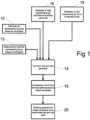
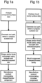
- the workpiece which is shaped by the shaping operation may then be incorporated in a final product, as outlined in the flowchart of Figure 1a .
- the workpiece shaped by the shaping operation may be a part of a mould cavity from which a component is moulded, and that component may then be incorporated in a final product, as outlined in the flowchart of Figure 1b .
- a set of CAD data 10 representing the required shape of the workpiece, and a set of measurement data 12 from measurements representing the actual shape of the workpiece, are received at a tool form and toolpath generator 14.
- the tool form and tool path generator 14 also receives available tool data from a database 16, representing the identities of tools which have already been used for some shaping processes, but are not at the end of their working life.
- a database of standard tool data 18 representing the forms of standard tools is also available to the tool form and toolpath generator 14. On the basis of this accumulated data, the tool form and tool path generator 14 performs various functions.
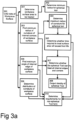
- One function of the tool path generator 14 is to determine, by comparing the CAD data 10 and the measurement data 12 at step 201 ( Figure 2 ) how much material is to be removed from the workpiece, and where the material is to be removed from, in order to bring the workpiece to the required shape and finish.
- determining the amount of material to be removed from the workpiece account is taken of immediate sub-surface damage which the workpiece has already suffered, and the amount of material to be removed is adjusted so that any damaged surface regions of the workpiece are removed, leaving a smooth and polished surface free from sub-surface cracking or other damage.
- the depth of material to be removed at each point is calculated from the difference between the measurement data 12 and the CAD data 10 of that point.
- the tool path generator 14 determines the amount of material to be removed from the workpiece at the point where the measurement data 12 and the CAD data 10 are closest together, and generates a tool path which will result in the removal of at least this minimum amount of material from all points on the surface of the workpiece, in order to ensure that any sub- surface damage is polished out.
- the tool form and tool path generator 14 analyses the required shape of the workpiece at step 202 to determine a form (shape) of tool which is able to treat all of the areas of the workpiece. This determination may involve a selection (step 203) from the used tools which are available (represented by available tool data 16 stored in database 250), or it may be a selection from a standard range of tools (based on the standard tool data 18 stored in database 250), or in some cases a non-standard tool form may be required and a bespoke tool will have to be produced.
- the tool form and tool path generator 14 After selecting or generating the shape and size (form) of the tool required to treat all of the workpiece surface, the tool form and tool path generator 14 then generates at step 204 a tool path which describes the movement required of the tool over the workpiece in order to remove the material from the workpiece to bring it to the required shape and finish.
- the combination 15 of tool path data and either the identity of an available tool, or a new standard or bespoke tool is then provided to a shaping apparatus 20.
- the workpiece is shaped by the shaping apparatus 20 moving the tool over the workpiece along the determined tool path to arrive at the required shape for the workpiece.
- the finished workpiece may form part of a final product, or may be a mould cavity in which a component is moulded for later incorporation into a final product.
- the tool path data will include the three-dimensional components of the movement of the tool relative to the workpiece.
- the tool path will thus define the tool "offset", i.e. the amount of deformation of the tool against the workpiece surface which defines the size of the tool footprint, at each point along the tool path.
- the tool path data may also define the speed of translation of the tool across the workpiece surface, which may be constant or which may vary at different parts of the tool path, and optionally also include data concerning a rotational speed of the tool and a precession angle of the tool rotation axis relative to the tool footprint on the workpiece surface.
- step 205 An important check to perform during the generation of the tool path is the collision check, step 205.
- This step simulates the shaping operation to ensure that at no time during the shaping operation does the tool stem or any other part of the tool mounting or the shaping machine collide with the workpiece.
- the tool path generating software may vary the tool path by changing the tool attitude, or the design of the tool may be altered for example to reduce or reshape the tool stem, and calculates a new tool path at step 204.
- the generation of the tool path is an iterative process which eventually arrives at a combination of a tool profile and a tool path which can treat all of the parts of the surface, which avoids collision with the workpiece, and which provides a treatment time which is not excessive.
- one of the inputs to the tool path generator may be a time limitation, specifying the maximum amount of time allowed for bringing the workpiece from its measured shape to the required shape.
- the tool path generator determines at step 206 the amount of wear dW that the tool will experience when performing this shaping operation, and verifies in steps 207 and 208 that the selected tool is capable of sustaining this amount dW of wear without exceeding a wear threshold TW indicative of the working life of the tool.
- the calculation of dW is based on the amount of material to be removed from the workpiece and the surface configuration of the tool. This check ensures that the tool will be able to complete the required shaping operation i.e. that the working surface of the tool will not become so worn during the shaping operation that the tool is unable to complete the operation.
- the tool path generator 14 selects an alternative tool form at step 209 and returns to step 204 to generate an alternative tool path to perform the required shaping operation.
- the tool path generator 14 When the tool path generator 14 arrives at a combination 15 of a tool selection and a tool path which can perform the required shaping operation without exceeding the wear threshold TW of the selected tool, the tool path generator 14 updates the database 250 at step 210. Then if the selected tool is one of the used tools available, then at step 212 the tool path data is provided to a shaping machine such as a CNC machining centre, together with the identity of the selected used tool. The machining centre then operates at step 20 to move the selected used tool over the workpiece following the tool path data in order to shape the workpiece.
- a shaping machine such as a CNC machining centre
- the tool path data is provided to the shaping machine at step 213, together with the identity of the selected standard tool.
- a standard tool may be provided to the machining centre, together with the tool path data, or the standard tool may be obtained from other sources. The machining centre then operates to move the selected standard tool over the workpiece following the tool path data in order to shape the workpiece.
- the tool path generator 14 If the tool path generator 14 is unable to generate a tool path which can be successfully followed by either an available used tool or a standard tool form, then the tool path generator will generate at step 203 a bespoke tool form and at step 204 a corresponding tool path for moving the bespoke tool over the workpiece to bring the workpiece to the required shape.
- the tool path generator 14 also calculates, at step 211, the threshold amount TW of tool wear that the bespoke tool can tolerate during its life, and feeds this to the database with the identity and form data for the bespoke tool.
- the bespoke tool is then manufactured at step 214 and provided to a shaping machine, together with the corresponding tool path data, and the shaping machine then operates to move the tool over the workpiece to shape the workpiece.
- the database is then updated to reflect the amount of wear suffered by the bespoke tool during the shaping operation.
- the tool path generator 14 maintains a database 250 which stores identity data for each individual tool, and for each tool also stores data concerning the tool form and a threshold amount of tool wear TW which can be sustained by the tool during its working life, i.e. before the tool becomes unusable. This threshold amount of wear TW is calculated based on the surface area and the shape of the tool.
- the database also stores, for each tool, an accumulated amount W of tool wear corresponding to the shaping operations which the tool has performed since its production.
- the surface of the workpiece is analysed to determine the shape of tool required in order to shape and/or finish all parts of the workpiece surface.
- a large radius tool can achieve a large treatment footprint and thus the surface of the workpiece can be shaped and/or finished in a short treatment time.
- the workpiece surface includes sharply curved concave areas, or edges where faces of the workpiece surface intersect at acute angles, then a large-radius spherical tool may not be able to treat these surface areas.
- the tool is able to enter these sharply-curved regions of the workpiece surface, but since the tool footprint is correspondingly reduced then the time for treating the surface will be increased. Furthermore, since the overall surface area of the tool will be reduced, each part of the tool surface will wear away at a greater rate than would be the case with a larger-radius tool.
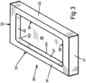
- FIG 3 is a perspective view of a sample component for shaping using the method of the present invention.
- the sample component is intended to form part of a mould cavity.
- the sample component illustrated comprises a generally rectangular block 30 having a pair of end surfaces 31 and 32 and a pair of side surfaces 33 and 34.
- a top surface 35 of the block there is a generally rectangular recess which has a flat base 36, a pair of vertical sides 37 and 38, and a pair of vertical ends 39 and 40.
- the sides and ends 37 to 40 are blended to the base 36 by a radiussed region R1, and to each other by larger-radius regions R2.
- the area of the sample component to be shaped/finished comprises the internal surfaces of the recess 36.
- the area of the sample component to be treated is thus formed mainly by flat surfaces, namely the base 36 and the sides and ends 37 to 40 of the recess.
- a smaller proportion of the surface to be treated comprises the small-radius highly curved region R1 blending the sides 37 to 40 of the recess to the base 36, and the larger-radius curved regions R2 blending the end walls 39 and 40 to the sidewalls 37 and 38.
- non-spherical tools which include a part of the tool surface optimised for treating the flatter areas of the workpiece, and one or more acutely-angled or sharply curved regions of the tool surface which are able to treat the internal corners of the workpiece.
- the part of the tool surface optimised for treating the flatter areas of the workpiece may be hemispherical or part-spherical, in order to provide a generally circular tool footprint on the workpiece.
- a spherical or part-spherical tool having a radius equal to the internal radius R1 of the blending region could be chosen, since such a tool would be able to engage all parts of the surfaces of the recess.
- the total surface area of such a tool would be extremely small, leading to a short working life for the tool.
- the size of tool footprint which such an extremely small tool could generate on the sample component is also small, so that only a very small area of the sample component can be treated at any time. This would result in an extremely long processing time for the small footprint to move over the comparatively large areas of the base 36 and side walls 37 to 40.
- the determination of the optimum shape and size of tool for the particular workpiece is made by an analysis of the workpiece surface data undertaken by a processor, using digital data representing the form (shape and dimensions) of the workpiece surface to be treated.
- This digital data 300 may be a CAD file defining the surface to be achieved.
- the first step in the analysis is to determine at step 301 the total area of the surface which requires treatment, as this defines a minimum radius for a spherical tool so as to provide sufficient surface area of abrasive material to be able to treat the surface area of the workpiece without wearing out the tool.
- the area to be treated comprises the combined areas of the base 36, the sidewalls 37 and 38, the end wall 39 and 40, the blending region R1 and the four curved corner regions R2.
- the minimum radius for a spherical tool with sufficient surface area to treat this area of the workpiece surface is determined.
- the second step in the analysis is to find, at step 303, the minimum radius of curvature of internal corners of the workpiece surface.
- This step establishes the maximum possible radius of a spherical tool which can treat the entire surface area, i.e. a tool which can enter the internal corners of the workpiece and engage all of the surface.
- the radius of the part of the surface area having maximum curvature i.e. minimum internal radius
- the largest spherical tool which can treat the entire surface is a tool of radius R1.
- the third step 305 is to compare the determined maximum radius of the tool from step 304 with the minimum radius determined in step 302. If the maximum radius from step 304 is greater than the minimum radius from step 302, then a spherical tool with a radius between these two limits is able to treat the entire surface area without wearing out the tool. There may be one or more "standard" size spherical tools whose radii are within this range.
- the minimum angle of the internal edges of the workpiece surface is determined from the CAD data 300.
- step 307 determines whether a spherical tool T having a radius within this range of radii (preferably one of the "standard" size tools) will be able to treat internal edges of the workpiece, i.e. lines of intersection of adjacent faces of the workpiece where the angle between the faces is less than 180°.
- the radius of the tool must be such that the tool is able to exert sufficient pressure on the surface, or generate sufficient offset, to treat the surface at the edge without exceeding the maximum permitted pressure or offset at areas adjacent the edge.
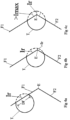
- Figures 4a to 4c are schematic side views of a spherical polishing tool approaching an internal corner or edge E in a workpiece formed at the intersection of two flat faces F1 and F2 of the workpiece.
- the spherical polishing tool T is positioned with an "offset" Ir so as to produce the required pressure on the workpiece, and this produces a generally circular treatment footprint of diameter Df on the flat face F1 of the workpiece.
- the tool offset at the edge E as seen in Figure 4b is initially less than the offset Ir required to treat the surface.
- the processing algorithm preferably tests first the "standard" tool sizes within the range at step 307, and selects the larger or largest radius tool from the successful candidates, i.e. the largest tool which can treat the internal edge E without exceeding the maximum permitted offset Imax. If all of the "standard" tool sizes within the range are too large to successfully treat the internal edges of the workpiece, the processing algorithm then determines whether a spherical tool with a radius at the lower limit of the range will be able to treat the internal edges. If it can, the processing algorithm may then iteratively proceed to determine the largest-radius spherical tool in the size range which can treat the internal edges of the workpiece.
- the surface data analyser then provides to the tool form generator data identifying the largest-radius spherical tool which satisfies the criteria of treating the internal corners and the internal edges of the workpiece, and is large enough to treat the entire workpiece area without wearing out the tool.
- step 305 determines that the maximum radius from step 304 (the maximum radius for a spherical tool which will treat the internal curves of the workpiece) is less than the minimum radius from step 302 (the minimum size spherical tool which will be able to complete the shaping process), then the largest spherical tool able to treat the internal corners of the workpiece has insufficient working surface area to treat the entire surface area without wearing out the tool.
- the processing proceeds to step 310 as a non-spherical tool is required in order to simultaneously provide sufficient working surface area to treat the entire workpiece and to provide one or more sharply-radiused ridge portions to treat the internal corners of the workpiece.
- such a tool has a spherical region of sufficiently large radius to provide sufficient working surface area of the tool, and one or more annular regions or ridges whose tips are of sufficiently small radius to treat the internal corners of the workpiece.
- Figures 5a and 5b show examples of non-spherical tools, in diametral section.
- the tool comprises a spindle 52 on which the tool head is mounted.
- the tool head is axisymmetrical about the axis of the spindle 52, and has a working surface which includes a generally hemispherical working surface portion 51, a generally conical working surface portion 52, and a generally flat working surface portion 53 surrounding the tool spindle.
- the conical portion 52 meets the hemispherical portion 51 in first annular ridge 54, and the conical portion 52 meets the flat portion 51 in a second annular ridge 55.
- Figure 5b shows an alternative form of non-spherical tool.
- the tool has a part-spherical region 56 which subtends an angle a at the centre of the sphere.
- the part spherical surface 56 is blended into a conical surface part 57, and the working surface is then rounded at a radiussed ridge 59 where the conical surface 57 meets a conical surface 58 which converges towards a flat top surface of the tool surrounding the tool spindle.
- the radius of the tip of the ridge 59 is substantially less than the radius of the part-spherical portion 56.
- the ridges 54, 55 and 59 are used to treat internal corners and/or edges of the workpiece which the part-spherical regions 51 and 56 are unable to effectively process.
- the tool is held against the workpiece at an appropriate orientation such that the ridges 54, 55 or 59 can engage with the internal edges and/or corners of the workpiece in order to treat these parts.
- the tool is held so that the part-spherical surface 51 or 56 engages the workpiece surface.
- the tools are formed from resilient material such as rubber or synthetic elastomers, and in some embodiments the working surfaces of the tools are covered with an array of substantially rigid pellets in which abrasive material is embedded. Such pelleted tools can be used without the need for an abrasive slurry in conjunction with the tool.
- the working surface of the tool is the rubber or synthetic elastomer material of the tool, and the tool is used in conjunction with an abrasive slurry
- the profile of the tool for example the extent of the part-spherical portion of the tool which is determined by the angle a subtended at the centre by the part-spherical portion of the tool, may be selected on the basis of data correlating surface curvature with the area of the surface having that curvature. This data may be presented in the form of a histogram such as is seen in Figure 4a .
- Figure 4d is a histogram representing the surface of the sample component of Figure 3 .
- the area to be treated which has the radius R1 is the smallest homogeneous area, and the blended corners of radius R2 have a slightly greater area.
- the largest area to be treated comprises the flat surfaces of the sidewalls 37 to 40 and the base 36 of the recess, which are indicated in the histogram as R3.
- the area with the most common curvature is R3, and thus the tool will be designed so that its part-spherical surface will polish the area R3, while the tool also has a portion of external radius R1 to treat the smallest-radius areas of the workpiece.
- the total areas of the parts R1, R2 and R3 of the component surface are added together to determine the amount of area to be treated, and this establishes the minimum radius of a spherical tool able to treat the workpiece, on the basis of the available working surface area of the tool.
- the angle a which determines how much of the tool surface is part-spherical depends on the ratio of the total area in the histogram which is above the minimum tool radius, to the total area in the histogram which is below the minimum tool radius. In the present example, this ratio is expressed as: R 3 : R 1 + R2
- the value of "a" should be such that the proportion of tool surface area that is spherical is the same as the proportion of workpiece surface area that will be polished by this spherical part of the tool. For example, if the spherical part of the tool is to be used to treat half of the workpiece surface area, then the value of a should be set so that half of the working surface of the tool is spherical in form. If most of the area to be treated is flat, then the angle a is larger, to provide a large part-spherical tool working surface for treating the flat areas.
- step 309 in Figure 3a where the distribution of curvature of the workpiece surface is determined.
- the requirements of the non-spherical tool form are established by determining what proportion of the tool should be spherical in shape, what radius that spherical part should have, and whether the tool requires one or more ridges or edges of small radius in order to treat sharply curved parts of the workpiece. When these requirements are determined, the profile of the tool can be established.
- a shaping tool for use in the process of the present invention may comprise a part-spherical resilient surface on which is disposed a flexible sheet bearing an array of substantially rigid pellets in which abrasive material such as diamond is embedded.
- the pellets are approximately disc-shaped and the diameter of each pellet is approximately 0.5mm, and the centres of adjacent pellets are arranged approximately 0.75mm apart so as to leave a gap of about 0.25mm between adjacent pellets.
- the pellets may be of different shapes, such as rectangular, hexagonal or triangular, and may be arranged in different patterns over the working surface of the tool.
- the pellets on a tool surface may be of several different shapes, and may be arranged in annular regions where each region contains pellets of one or more particular shape.
- abrasive particles used in the pellets are diamond, cubic boron nitride (CBN), alumina and silica.
- Diamond particles are indicated for shaping hard ceramic materials such as silicon carbide or tungsten carbide.
- CBN particles may be preferred, while for shaping soft materials such as glass then alumina or silica particles may be used.
- Other abrasive materials may be used as appropriate, for shaping particular workpiece materials.
- the particle size of the abrasives may be from 1 to 100 ⁇ m.
- the particle size of the abrasives is from 3 to 15 ⁇ m, and a particle size of 9 ⁇ m for a diamond abrasive, held in a nickel or resin pellet matrix, has been found to be particularly effective for shaping silicon carbide.
- the grinding slurry may contain abrasive particles of from 1 to 9 ⁇ m in diameter, suspended in an aqueous medium.
- the abrasive particles may be of cerium oxide, aluminium oxide or diamond, or any other suitable abrasive material appropriate to the material of the workpiece being shaped.
- Figures 5c to 5f illustrate stages in the manufacture of a bespoke tool from a tool blank 500.
- the tool blank 500 comprises a tool spindle 501, on one end of which is formed an elastomer block 502, formed from a resilient material such as polyurethane, natural or synthetic rubber, nitrile rubber or silicone.
- the tool spindle 501 is held for example in a lathe (not shown) and rotated.
- a shaping tool 504 is applied to the elastomer block 502 to form the block into a tool 505 having the required axisymmetric profile coaxial with the spindle 501.
- the elastomer block 502 may be a homogenous block of elastomer material, preferably with a hardness on the Shore A scale of between about 40 and 90, preferably about 60.
- the shaped tool may be used to shape the workpiece by applying the tool to the workpiece surface in combination with an abrasive slurry.
- the working surface of the tool is covered with a flexible sheet of material carrying a number of rigid pellets, the pellets containing abrasive particles.
- a suitable shape is cut from a sheet 60 of pelleted material.
- the shape may have a generally circular central area 506 and a number of lobes or "petals" 507 radiating out from the central area 506, the shape and dimensions of the central area 506 and the petals 507 being such that they can be wrapped around the profiled tool 505 to cover or substantially cover its working surface.
- Other shapes are possible for the pelleted sheet, provided that they can be folded to cover the working surface of the tool. For example, if the tool simply has a part-spherical working surface which subtends a small angle a at the centre of the sphere, then a circular shape without "petals" may be suitable.
- the cut sheet of pelleted material and the tool 505 are then placed between two mould halves 508 and 509 as seen in Figure 5f and 5g , and vulcanised together under heat and pressure to bond or vulcanised the sheet S to the surface of the tool 505 and form a pelleted tool.
- the sheet 60 of pelleted material may be firstly laid over the cavity in the lower half 509 of the mould, and pushed into the cavity using the tool 505.
- the petals 507 may then be folded over the upper part of the tool 505 and temporarily secured in place, while the upper half 508 of the mould is brought down to close the cavity.
- the shaping of the upper mould half may be such that the closing movement of the mould causes the petals 507 to assume their correct positions within the mould.
- Heat and pressure are then applied to vulcanise the tool and to bond the cut sheet 60 thereto.
- the mould may be heated to about 150°C or up to about 200°C or more, and the tool may be held in the mould for up to 10 minutes.
- the tool is then released from the mould, and checked to ensure that the pelleted working surface conforms to the required surface profile of the tool.
- a further shaping or dressing step may be required to ensure that the tool conforms to the required shape, for example by removing some material from the pellets using a grinding wheel or other shaping tool.
- a tool identification code can then be applied to the tool, this code optionally also including information regarding a nominal tool size, a preferred precession angle for operating the tool, maximum expected tool life and maximum tool offset in use, as well as any other relevant information for the user such as whether the tool is required to be used with or without a grinding slurry, and the preferred characteristics of such a grinding slurry.
- the conditioning cycle may be performed after the tool has been produced, by rotating and manipulating the tool while pressing it against a conditioning surface, so that each part of the working surface of the tool contacts the conditioning surface for a time sufficient to alter the working surfaces of the pellets until the surface structure of the pellets stabilises, and the rate at which material is removed from the conditioning surface becomes substantially constant.
- the flexible sheet may be conditioned prior to cutting the sheet 60 to the required shape for applying to the tool during manufacture.
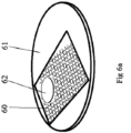
- the uncut sheet may be conditioned as illustrated in Figure 6a , by mounting a sheet 60 of the pelleted material on a supporting surface 61, and then pressing a conditioning "puck" 62 into contact with the sheet and moving the puck 62 over the area of the sheet 60 to condition the exposed surfaces of the pellets.
- the supporting surface 61 may be static, and the puck 62 may be moved relative to the supporting surface 61 and the sheet 60.
- the supporting surface 61 may be movable and/or rotatable to move the sheet 60 relative to the puck 62.
- the lateral drag force exerted on the puck 62 by the sheet 60 may be measured by a measuring device (not shown) as the conditioning process progresses, and will decrease from a higher initial value eventually to level out at a substantially constant value.
- the conditioning process is deemed to be completed when this substantially constant value is reached, and can be controlled by measuring the drag force and determining that the conditioning process is completed when the drag force ceases to vary with time.
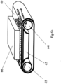
- Figure 6b illustrates an alternative arrangement for conditioning the flexible sheet.
- the flexible sheet 60 is formed into an endless belt, and is looped over a pair of rollers 63 and 64 with the pelleted side of the sheet facing outwards.
- a supporting surface 65 is arranged on the inner side of one run of the belt, and a conditioning block 66 is pressed against the outer, pelleted side of that run of the belt.
- Rollers 63 and 64 are then rotated to move the belt 60 between the supporting surface 65 and the conditioning block 66, so that the pellets engage with and move relative to the conditioning block 66.
- the lateral force produced on the conditioning block 66 by the pellets on the sheet 60 may be measured, and conditioning may be considered to be complete when this force reaches a constant value.
- the conditioning operation may take up to 15 or 30 minutes, or possibly longer.
- the rate at which material is removed from the puck 62 or the conditioning block 66 may be measured at intervals during the conditioning cycle, and the conditioning cycle may be terminated when the removal rate becomes stable.
- the pre-conditioned sheets or belts of mesh may then be cut into the required shape to cover a tool body, for example by stamping the mesh sheets in a die or by cutting the sheets using any suitable cutting tool or means.
- the pre-conditioned cut mesh sheet may then be applied to the tool, for example by placing the mesh sheets into a mould, introducing the tool into the mould and vulcanising the tool and mesh together as described in relation to Figure 5 .
- a further short conditioning step may be applied when the finished tool is removed from the mould, by pressing the tool against a conditioning surface and rotating the tool to expose all parts of the tool surface to the conditioning surface in order to complete the conditioning process.
- the objective of the conditioning process is to shape the abrasive particles in the pellets so that they have a flattened exposed surface and a slightly tilted attitude, with a debris pocket at the front and binder up-stand at the back.
- Figure 7a is a micrograph photograph of part of the surface of a conditioned pellet, showing a diamond particle 70 which has been conditioned by moving a conditioning surface relative to the diamond in the direction shown in the arrow of Figure 7a .
- the conditioning surface is moved upwards and to the right as seen in the figure, and the leading edge of the diamond particle extends upward and to the left, substantially at right angles to the arrow A.
- the diamond particle 70 has an exposed edge 71.
- the diamond particle 70 is seen embedded in the material 72 forming the pellet.
- the conditioning puck or block is shown as reference numeral 66, and moves relative to the diamond particle 70 in the direction of arrow A, which is roughly perpendicular to the line of the exposed edge 71.
- the "front" of the diamond is its leading edge 71 when considered in the direction it will travel across the workpiece when the tool is rotated and contacted to the workpiece.
- the debris pocket 73 situated adjacent the edge 71 of the diamond particle 70 and illustrated in Figure 7b is the substantially triangular area seen to the left of the edge 71 in Figure 7a .
- the exposed surface 74 of the diamond particle 70 is seen in Figure 7b and is slightly tilted at an angle b to the surface of the pellet material 72. In the conditioned tool, the "nodular" form of the surface of the pellets is reduced and smoothed, and exposed abrasive particles are flattened.
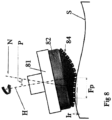
- Figure 8 is a schematic side view of the tool as it moves in contact with the free-form workpiece surface.
- the body of the tool 81 is moved toward the workpiece surface S until the pellets 84 contact the workpiece surface, and is then moved further towards the workpiece surface by an "offset" amount such that the elastic membrane 82 deforms, pressing the pellets 84 flat onto the workpiece surface S and creating a generally circular tool footprint Fp where the tool surface is in contact with the workpiece surface.
- the tool body 81 is then rotated about the spindle axis H, which is set at a precession angle P relative to the local normal N to the workpiece surface S, so that the pellets 84 in an annular region of the tool contact the workpiece surface S, in the tool footprint, and move across the workpiece surface.
- a precession angle P relative to the local normal N to the workpiece surface S
- the pellets 84 in an annular region of the tool contact the workpiece surface S, in the tool footprint, and move across the workpiece surface.
- lifting the tool body 81 vertically will reduce the "offset" Ir, reducing the deformation of the cup 82 and decreasing the diameter of the tool footprint on the workpiece surface S.
- the tool is moved in translation over the workpiece surface at a controlled "feed" speed of from 10 to 1000 mm/minute, preferably about 150mm/minute.
- the tool is rotated about the spindle axis H at between about 50 and 1500 rpm.
- the size of the tool footprint is varied by adjusting the "offset" distance Ir between the surface of the workpiece and the centre of the part-spherical surface of the tool.
- the force with which the tool is pressed against the workpiece is either controlled by controlling the fluid pressure inside the cup of the tool, or by adjusting the offset.
- the tool rotation speed and the angle P and direction of the precession axis are also controlled, and in conjunction with the tool footprint Fp and pressure determine the instantaneous rate at which material is removed from the workpiece at any point along the tool path.
- the tool "feed" speed By controlling the tool "feed" speed, the time which the tool spends at each point along the tool path is controlled and thus the amount of material removed from each point along the tool path is determined.
- Control of the direction of the precession axis determines the relative direction of movement of the tool to the workpiece at each point on the tool path.
- the control of the instantaneous direction in which the pellets move over the surface may be effected with the objective that polishing artefacts (grooves, ridges) are not left in the workpiece surface, for example by continuously varying the direction of relative movement of the pellets and the workpiece.
- the direction of movement of the pellets over the surface may be controlled such that any polishing marks left on the surface are aligned in a particular direction or directions.
- the "feed" speed at which the tool moves along the tool path is also controlled, to ensure that the required amount of material is removed at each point along the path, and the required surface finish is achieved.
- the cutting regime of the particles changes from a ductile regime in which material is removed with minimal cracking and sub-surface damage to the workpiece, to a "brittle" cutting regime in which surface cracks and sub-surface damage appear.
- Figure 9a is a schematic illustration of the testing method, which involves moving the tool across a test surface without rotating the tool about its precession axis H, while continuously increasing the offset Ir.
- the test may be carried out on a dedicated test apparatus, or may be carried out by mounting the workpiece in a shaping machine and moving the tool over the workpiece surface. In the illustrated test process, the tool is moved along a flat surface by a distance of 25 mm, while the tool offset is increased from 0 to 0.4 mm.
- the test surface is preferably made from the same material as the workpiece which is to be shaped, or may be a part of the workpiece to be shaped.
- This test method is suitable both for pelleted tools and for tools shaped from an elastomer blank.
- the test is carried out after conditioning of the tool.
- the test is carried out by firstly pressing the tool into dry abrasive powder to embed abrasive particles into the surface of the tool, and the tool is then drawn across the test surface as the tool offset is increased. The analysis of the results is the same in both cases.
- Figure 9B illustrates the pattern of scratches formed on the test surface by the abrasive particles in the pellets of an elastic tool.
- the increasing offset not only increases the pressure of the tool surface against the workpiece, but also increases the size of the tool footprint and brings more abrasive particles into contact with the test surface, resulting in a larger number of scratches.
- the largest number of scratches is seen. The depth of the scratches increases progressively from left to right as seen in the Figure, as the pressure against the workpiece increases.
- Figures 9c to 9f are enlarged schematic views showing the surface structures of the respective areas c, d, e and f illustrated in Figure 9b .
- the indentations or scratches 91 produced by the abrasive particles moving over the test surface have, in the area c, predominantly smooth walls. As the test movement progresses, the walls of the indentations become progressively more fractured. The fracturing of the walls is illustrated schematically by the irregular patches 92.
- the enlarged detail in Figure 9f shows the scratch 91 with a smooth wall profile, which becomes irregular in the patch 92.
- a ductile to brittle transition is identified as the point at which the walls of the indentations are irregular (fractured) for more than a threshold amount, for example 10%, of the length of the test sample considered.
- a threshold amount for example 10%
- lengths L1 and L3 have smooth walls indicate of ductile cutting
- the length L2 has irregular fractured walls indicative of brittle cutting.
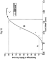
- Figure 10 illustrates the relationship between tool offset and the percentage of fractured walls of the indentations for a silicon carbide test sample.
- the percentage of fractured walls is initially zero, and rises slowly to approximately 10% in this test sample. The percentage of fractured walls then rises rapidly, reaching 90% fractured at an offset of 0.215. Thereafter, the percentage of fractured walls levels off at about 95% for offsets greater than 0.25.
- the amount of offset Imax which results in the threshold percentage of fracturing of the walls of the indentations can be determined. This inspection may be carried out by capturing images of the indentations, and using image processing to analyse the edges of the indentations and calculate the percentage of the edges which are smooth and linear, and the percentage which are fractured and irregular.
- a test processor can establish the relationship between the amount of offset and the percentage of fractured edges, and can establish the amount of offset at which the cutting regime changes from ductile cutting to brittle cutting as the percentage of fractured edges passes a predetermined threshold, for example 10%.
- the tool path may be optimised so that the value of the offset at any point along the tool path is maximised up to the limit of ductile cutting, or alternatively the tool path may be calculated such that the value of the offset does not exceed a particular proportion, for example 80%, of the maximum permissible offset for ductile cutting.
- the tool path generator determines the amount of wear dW that the tool will experience when performing this shaping operation.
- the tool path generator first calculates the total amount of material to be removed from the workpiece and the surface configuration of the tool, based on the measurement data representing the initial form of the workpiece, and the CAD data representing the final form. Using this information and a "Grinding Ratio" which depends on the relative hardnesses of the workpiece and the working surface of the tool, the amount of wear dW that the tool will suffer when performing this shaping operation can be determined.
- the "Grinding Ratio" i.e. the ratio between material removed from the workpiece and wear of the grinding tool may be determined experimentally for particular tool/workpiece combinations.
- FIG. 11a schematically shows a part-spherical resilient tool pressed against a flat surface, with a plot of pressure against radius for the tool footprint shown below the figure. The plot shows that the pressure exerted by the tool is highest at the centre of the tool footprint, where the part-spherical surface is most deformed.
- the pressure at each point in the tool footprint should also be such that abrasive particles in the working surface of the tool are pressed against the workpiece surface with a force which results in ductile cutting of the workpiece.
- the pressure at the centre of the footprint may result in the abrasive particles of the tool being pressed against the surface of the workpiece with sufficient force that brittle grinding takes place, resulting in sub-surface damage.
- the pressure exerted by the tool over the footprint should be as uniform as possible.
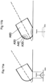
- the main body A60 of the tool is produced from material with a Shore A hardness of about 60. Extending around the free end of the tool is a first region A50 generally "L" shaped in cross-section, which has an exposed area near to the tip of the tool, and a second exposed area approximately on the tool shoulder where the part-spherical region meets the main tool body.
- region A40 Nested within the region A50 is a region A40 also of generally "L" shaped cross-section, and exposed on the surface adjacent the two areas of exposure of the portion A50. Filling the generally "L" shaped profile of the region A40 is a ring of material A30 which is exposed on the surface of the tool as a continuous band.
- the ring A30 is formed from a softer material than the region A40, which in turn is softer than the region A50 which in turn is softer than the main body A60 of the tool.
- the Shore A hardnesses of the regions A50, A40, and a 30 may be 50, 40 and 30 respectively. The precise positioning of these regions will be such that at the intended precession angle with which the tool is to be used, the softest ring A30 passes across the centre of the tool footprint as the tool rotates relative to the workpiece.
- the tool may be spherical or part-spherical, or may have a bespoke profile suited to a particular workpiece.
- the positions of the regions of differing hardness will depend on the intended precession angle of the tool.
- the regions may be produced by inlaying toroidal regions of material of different hardnesses within the spherical outline of the tool.
- the tool may be produced by assembling concentric cylinders of materials of different hardnesses to form a tool blank from which the tool profile may be machined, as illustrated in Figure 11c .
- This tool is formed from a central core 110 surrounded by four sleeves 111, 112, 113 and 114 of resilient material of different hardnesses.
- the central core 110 and the outermost sleeve 114 are of relatively harder material
- the intermediate sleeves 111 and 113 respectively adjacent to the central core 110 and the outermost sleeve hundred and 14 are made of a softer material
- the sleeve 112 situated between the intermediate sleeves 111 and 113 is of a softer material still.
- the central core 110 and the outermost sleeve 114 are formed from a material of Shore A hardness 60
- the intermediate sleeves 111 and 113 are formed from a material of Shore A hardness 50
- the sleeve 112 is formed from a material of Shore A hardness 40.
- the dimensions of the sleeves are arranged so that the softest material is exposed on the part-spherical surface of the tool at a point which coincides with the centre of the tool footprint when the tool is operated at the design precession angle.
- the central areas of the tool footprint are the most deformed parts of the tool, but since these are formed from the softest material the pressure generated on the workpiece is substantially constant over the tool footprint
- the tool may be formed by a 3-D printing technique using different hardnesses of material for the different regions of the tool.
- the tool may have a contoured supporting core over which varying depths of rubber are deposited to form a spherical tool surface, the differing depths of rubber between the core and the workpiece, as measured in radial directions of the spherical tool, producing a substantially constant contact pressure over the tool footprint at the design precession angle.
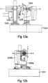
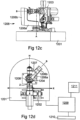
- a shaping machine for shaping a workpiece using the tools and methods of the present invention is illustrated in Figures 12a to 12d .
- the shaping machine 1200 comprises a robust table 1201 resistant to vibrations.
- the turntable 1204 is mounted on the Y -slide mechanism 1203 via a z movement mechanism (not shown) for movement of the turntable 1204 in the z direction.
- the turntable 1204 has a holding surface onto which a workpiece 1205 may be mounted for shaping and/or finishing.
- This arrangement provides for motion of the workpiece 1205 in four axes, namely linear movement in the x, y and z directions, and rotation about the c axis. It will be appreciated that in the arrangement shown, the rotation axis c is parallel to the movement axis z.
- a tool support arm 1206 which is generally "L" shaped, having a generally horizontal base part 1206a and a generally vertical upright 1206b.
- the tool support arm is mounted to the table 1201 at the end of the base part 1206a remote from the upright 1206b for rotation about a vertical axis A.
- a tool holder 1207 is mounted to the upright, so as to be rotatable relative to the upright about horizontal axis B.
- a rotary tool 1208 is mounted for rotation relative to the tool holder, about an axis H which is set at an angle to the axis B about which the tool holder 1207 rotates relative to the upright 1206b.
- the rotary tool 1208 has a part-spherical working surface, which is arranged so that the rotation axes A, B and H coincide at the centre of the part-spherical surface.
- the arrangement is such that rotation of the tool arm 1206 about the axis A rotates the part-spherical surface without moving the tool in translation, and rotation of the tool holder 1207 about the axis H likewise does not move the tool in translation but merely alters the plane of the precession angle between the tool rotation axis B and the tool holder axis H.
- the processor apparatus 1209 may include input means 1210 such as a keyboard, a port for external input signals or a disk drive, to receive process parameters and control instructions for controlling the motions of the workpiece and the tool.
- input means 1210 such as a keyboard, a port for external input signals or a disk drive, to receive process parameters and control instructions for controlling the motions of the workpiece and the tool.
- a display means 1211 may be provided to display information to the machine operator.
- the shaping machine 1200 shapes the workpiece, using the determined tool path from the tool path generator 14 in combination with the selected or manufactured tool.
- the processor apparatus 1209 receives the tool path data from the tool path generator 14, the selected or manufactured tool 1208 is mounted in the tool holder 1207, and the processor apparatus 1209 controls the shaping machine 1200 to move the tool 1208 along the tool path relative to the workpiece in accordance with the tool path data.
- the shaping machine 1200 may include a sensor to detect an identifying component and/or marking on the tool 1208, the sensor providing an output to the processor apparatus 1209 to ensure that the correct tool path is used to control movement of the tool 1208.
- the sensor may be an RFID sensor and the identifying component may be an RFID tag, or the sensor may be an optical detector to detect a marking such as a barcode or a QR code marked on the tool.
- the tool path data received from the tool path generator 14 may include data identifying the tool to be used, and also may include data identifying the workpiece.
- the workpiece may be marked with an identifying tag such as a barcode or an RFID tag, which is readable by the or a sensor associated with the shaping machine 1200.
- the processor apparatus 1209 may be arranged so that the shaping operation can only take place if the identifying data of the tool and the workpiece coincides with identifying data received from the tool path generator 14. This will ensure that the correct tool, and tool path data, are used to shape the workpiece for which the tool path data has been calculated.
Landscapes
- Engineering & Computer Science (AREA)
- Mechanical Engineering (AREA)
- Manufacturing & Machinery (AREA)
- Physics & Mathematics (AREA)
- Fluid Mechanics (AREA)
- Grinding And Polishing Of Tertiary Curved Surfaces And Surfaces With Complex Shapes (AREA)
- Grinding-Machine Dressing And Accessory Apparatuses (AREA)
- Numerical Control (AREA)
- Constituent Portions Of Griding Lathes, Driving, Sensing And Control (AREA)
- Polishing Bodies And Polishing Tools (AREA)
Claims (12)
- Verfahren zum Formen einer Oberfläche eines Werkstücks, umfassend die Schritte zum:Messen des Werkstücks, um Messdaten der zu formenden Oberfläche (S) zu erhalten;Vergleichen der erhaltenen Messdaten mit Daten, welche die erforderliche Form der Oberfläche des Werkstücks darstellen, um eine Menge und Verteilung von abzutragendem Material zubestimm
en;Analysieren der Daten, welche die erforderliche Oberflächenform der Werkstückoberfläche darstellen, um Formeigenschaften der zu formenden Oberfläche (S) zu bestimmen;Bereitstellen eines Formgebungswerkzeugs (81) mit einer Größe und Form, das alle Teile der zu formenden Oberfläche (S) auf der Grundlage der bestimmten Formeigenschaften bearbeiten kann;Bestimmen eines Werkzeugwegs zum Bewegen des Formgebungswerkzeugs (81) über die zu formende Oberfläche (S), um das Material von der Oberfläche (S) abzutragen, wobei der Werkzeugweg einen Werkzeugversatz an allen Punkten entlang des Werkzeugwegs definiert, wobei der Werkzeugversatz der Betrag einer Verformung des Werkzeugs (81) gegenüber der Werkstückoberfläche (S) ist; undFormen des Werkstücks durch Anbringen eines Formgebungswerkzeugs (81), das die bestimmte Größe und Form aufweist, in einer Spannvorrichtung (1207) und Bewegen des Formgebungswerkzeugs (81) über die Oberfläche (S) der Werkstückoberfläche unter Verwendung des bestimmten Werkzeugwegs, um das Material von der Werkstückoberfläche (S) abzutragen, wobei der Werkzeugversatz an allen Punkten entlang des Werkzeugwegs einen maximalen Werkzeugversatz nicht überschreitet und wobei der maximale Werkzeugversatz derart ist, dass die Formgebung des Werkstücks an allen Punkten entlang des Werkzeugwegs innerhalb einer verformbaren Regelung bleibt;wobei entweder das Formgebungswerkzeug eine abrasive Arbeitsoberfläche (84) aufweist oder bei der Formgebung des Werkstücks eine abrasive Aufschlämmung zwischen dem Formgebungswerkzeug und dem Werkstück bereitgestellt wird. - Verfahren nach Anspruch 1, wobei die Formeigenschaften den Gesamtbereich, die minimale Krümmung und die Kantenwinkel und/oder Krümmungsverteilung der Oberfläche des zu formenden Werkstücks beinhalten.
- Verfahren nach Anspruch 1 oder 2, wobei der Schritt des Bereitstellens des Formgebungswerkzeugs (81) das Auswählen eines Formgebungswerkzeugs aus einer Vielzahl von Formgebungswerkzeugen umfasst.
- Verfahren nach Anspruch 1 oder 2, wobei der Schritt des Bereitstellens eines Formgebungswerkzeugs die Herstellung eines Formgebungswerkzeugs (81) umfasst, das eine Größe und Form aufweist, mit der alle Teile der zu formenden Oberfläche (S) bearbeitet werden können.
- Verfahren nach einem der Ansprüche 1 bis 4, weiter beinhaltend:Pflegen einer Datenbank, in der für eine Vielzahl von Formgebungswerkzeugen (81) Kenndaten, Forminformationen, der aktuelle Verschleißbetrag und Gesamtverschleißbetrag gespeichert werden, dem jedes Werkzeug standhalten kann;Analysieren der bestimmten Menge und Verteilung des abzutragenden Materials, um einen Verschleißbetrag zu bestimmen, der durch die Durchführung des Formgebungsvorgangs am Formgebungswerkzeug verursacht wird;Bestimmen eines minimalen Oberflächenbereichs für das Formgebungswerkzeug, um dem bestimmten Verschleißbetrag standzuhalten; undBestimmen einer Größe für das Formgebungswerkzeug auf der Grundlage des bestimmten minimalen Oberflächenbereichs.
- Verfahren nach Anspruch 5, wobei, nachdem ein Formgebungswerkzeug (81) einen Formgebungsvorgang abgeschlossen hat, die Datenbank aktualisiert wird, um den bestimmten Verschleißbetrag zu dem aktuellen, für dieses Formgebungswerkzeug gespeicherten Verschleißbetrag zu addieren.
- Verfahren nach Anspruch 5, das den Schritt des Vergleichens der Summe des bestimmten Verschleißbetrags und des aktuellen Verschleißbetrags des Formgebungswerkzeugs (81) mit dem Gesamtverschleißbetrag des Formgebungswerkzeugs beinhaltet; und
wenn die Summe den Gesamtverschleißbetrag übersteigt, Auswählen oder Herstellen eines Alternativwerkzeugs. - Einrichtung zum Formen eines Werkstücks, umfassend:
Speichermittel zum Speichern von:Messdaten der Oberfläche (S) des zu formenden Werkstücks;Daten, welche die erforderliche Oberflächenform der Oberfläche (S) der Werkstückoberfläche darstellen;Prozessormittel zum:Bestimmen einer Menge und Verteilung des abzutragenden Materials auf der Grundlage der erhaltenen Messdaten und der Daten, welche die erforderliche Oberflächenform darstellen;Analysieren der Daten, welche die erforderliche Oberflächenform des Werkstücks darstellen, um Formeigenschaften der zu formenden Oberfläche (S) zu bestimmen;Bestimmen der Größe und Form eines Formgebungswerkzeugs (81), das auf der Grundlage der bestimmten Formeigenschaften alle Teile der zu formenden Oberfläche bearbeiten kann;Bestimmen eines Werkzeugwegs zum Bewegen des Formgebungswerkzeugs (81) über die zu formende Oberfläche (S), um das Material von der Oberfläche (S) abzutragen, wobei der Werkzeugweg einen Werkzeugversatz an allen Punkten entlang des Werkzeugwegs definiert, wobei der Werkzeugversatz der Betrag einer Verformung des Werkzeugs (81) gegenüber der Werkstückoberfläche (S) ist; undMittel zum Bereitstellen eines Formgebungswerkzeugs (81), das die bestimmte Größe und Form aufweist;eine Formgebungsmaschine (1200), die eine Spannvorrichtung (1207) zum Anbringen des Formgebungswerkzeugs (81) und ein Steuermittel zum Steuern der Spannvorrichtung (1207) beinhaltet, um das Formgebungswerkzeug (81) unter Verwendung des bestimmten Werkzeugwegs über die Oberfläche (S) des Werkstücks zu bewegen, um das Material von der Werkstückoberfläche (S) abzutragen, wobei der Werkzeugversatz an allen Punkten entlang des Werkzeugwegs einen maximalen Werkzeugversatz nicht überschreitet und wobei der maximale Werkzeugversatz derart ist, dass die Formgebung des Werkstücks an allen Punkten entlang des Werkzeugwegs innerhalb einer verformbaren Regelung bleibt;wobei entweder das Formgebungswerkzeug (81) eine abrasive Arbeitsoberfläche (84) aufweist oder bei der Formgebung des Werkstücks eine abrasive Aufschlämmung zwischen dem Formgebungswerkzeug (81) und dem Werkstück bereitgestellt wird. - Einrichtung nach Anspruch 8, wobei das Mittel zum Bereitstellen eines Formgebungswerkzeugs (81) umfasst:eine Vielzahl von Formgebungswerkzeugen; undAuswahlmittel zum Auswählen eines aus der Vielzahl von Formgebungswerkzeugen.
- Einrichtung nach Anspruch 8, wobei die Mittel zum Bereitstellen eines Formgebungswerkzeugs Mittel zur Herstellung eines Formgebungswerkzeugs (81) der bestimmten Größe und Form umfassen.
- System zum Formen eines Werkstücks, umfassend:eine Vielzahl von Formgebungswerkzeugen (81);eine Formgebungsmaschine (1200) zum Bewegen eines Formgebungswerkzeugs (81) entlang eines Werkzeugwegs über eine Werkstückoberfläche (S);Messmittel zum Erzeugen von Daten, welche die tatsächliche Form der Werkstückoberfläche (S) darstellen;einen Speicher zum Speichern von:Daten, welche die tatsächliche Form der Werkstückoberfläche (S) darstellen;Daten, welche die erforderliche Form der Werkstückoberfläche darstellen;Kenn-, Form- und Verschleißdaten, die sich auf jedes der Vielzahl von Formgebungswerkzeugen beziehen;Prozessormittel zum:Bestimmen der erforderlichen Form eines Formgebungswerkzeugs auf der Grundlage der Daten, welche die erforderliche Form der Werkstückoberfläche darstellen;Auswählen eines Formgebungswerkzeugs (81) aus der Vielzahl von Formgebungswerkzeugen mit einer Größe und Form, das alle Teile der zu formenden Werkstückoberfläche (S) bearbeiten kann;Bestimmen der Menge und Verteilung des von der Werkstückoberfläche (S) abzutragenden Materials auf der Grundlage der Daten, welche die tatsächliche Form darstellen, und der Daten, welche die erforderliche Form der Werkstückoberfläche darstellen;Bestimmen eines Werkzeugwegs zum Bewegen des ausgewählten Formgebungswerkzeugs über die Werkstückoberfläche (S) in einem Formgebungsvorgang, um das Material von der Werkstückoberfläche (S) abzutragen, wobei der Werkzeugweg einen Werkzeugversatz an allen Punkten entlang des Werkzeugwegs definiert, wobei der Werkzeugversatz der Betrag einer Verformung des Werkzeugs (81) gegenüber der Werkstückoberfläche (S) ist;wobei das ausgewählte Formgebungswerkzeug (81) und Daten, die den bestimmten Werkzeugweg darstellen, der Formgebungsmaschine (1200) bereitgestellt werden; unddie Formgebungsmaschine (1200) betreibbar ist, um das Werkstück durch Bewegen des ausgewählten Formgebungswerkzeugs über die Werkstückoberfläche (S) entlang des bestimmten Werkzeugwegs zu formen, wobei der Werkzeugversatz an allen Punkten entlang des Werkzeugwegs einen maximalen Werkzeugversatz nicht überschreitet und wobei der maximale Werkzeugversatz derart ist, dass die Formgebung des Werkstücks an allen Punkten entlang des Werkzeugwegs innerhalb einer verformbaren Regelung bleibt;
wobei entweder das Formgebungswerkzeug (81) eine abrasive Arbeitsoberfläche (84) aufweist oder bei der Formgebung des Werkstücks eine abrasive Aufschlämmung zwischen dem Formgebungswerkzeug (81) und dem Werkstück bereitgestellt wird. - System nach Anspruch 11, wobei:
die gespeicherten Verschleißdaten, die sich auf jedes der Vielzahl von Formwerkzeugen beziehen, einen aktuellen Verschleißbetrag und einen maximalen Verschleißbetrag beinhalten, und das Prozessormittel weiter betreibbar ist zum:Bestimmen eines erwarteten Werkzeugverschleißbetrags infolge der Durchführung des Formgebungsvorgangs;Vergleichen der Summe des erwarteten Verschleißbetrags und des aktuellen Verschleißbetrags des ausgewählten Werkzeugs mit dem maximalen Verschleißbetrag des ausgewählten Werkzeugs; undwenn die Summe den maximalen Verschleißbetrag überschreitet, dann ein anderes Werkzeug ausgewählt wird.
Applications Claiming Priority (2)
| Application Number | Priority Date | Filing Date | Title |
|---|---|---|---|
| GB1621699.6A GB2557952B (en) | 2016-12-16 | 2016-12-16 | Methods and apparatus for shaping workpieces |
| PCT/GB2017/053773 WO2018109501A2 (en) | 2016-12-16 | 2017-12-15 | Methods and apparatus for shaping workpieces |
Publications (3)
| Publication Number | Publication Date |
|---|---|
| EP3554760A2 EP3554760A2 (de) | 2019-10-23 |
| EP3554760B1 true EP3554760B1 (de) | 2024-02-14 |
| EP3554760B8 EP3554760B8 (de) | 2024-05-29 |
Family
ID=58284654
Family Applications (1)
| Application Number | Title | Priority Date | Filing Date |
|---|---|---|---|
| EP17832318.4A Active EP3554760B8 (de) | 2016-12-16 | 2017-12-15 | Verfahren und vorrichtung zum formen von werkstücken |
Country Status (11)
| Country | Link |
|---|---|
| US (1) | US11958165B2 (de) |
| EP (1) | EP3554760B8 (de) |
| JP (1) | JP2020504682A (de) |
| KR (1) | KR20190096388A (de) |
| CN (1) | CN110177650B (de) |
| DK (1) | DK3554760T3 (de) |
| GB (1) | GB2557952B (de) |
| PL (1) | PL3554760T3 (de) |
| PT (1) | PT3554760T (de) |
| TW (1) | TW201832031A (de) |
| WO (1) | WO2018109501A2 (de) |
Families Citing this family (9)
| Publication number | Priority date | Publication date | Assignee | Title |
|---|---|---|---|---|
| JP6957096B2 (ja) | 2017-08-22 | 2021-11-02 | 株式会社ディスコ | ドレッシングボード、その使用方法及び切削装置 |
| CH716246A1 (fr) * | 2019-06-03 | 2020-12-15 | Watch Out Sa | Module d'usinage et machine-outil comprenant une unité de suivi de l'usure de l'outil, et procédés de détection de la position, du profil et de l'usure de l'outil. |
| CN112440203B (zh) * | 2019-09-03 | 2022-04-05 | 芯恩(青岛)集成电路有限公司 | 一种晶圆研磨系统和晶圆研磨方法 |
| IT202000018826A1 (it) * | 2020-07-31 | 2022-01-31 | Scm Group Spa | Macchina per la lavorazione di pezzi in legno e simili, provvista di un programma di acquisizione ed elaborazione di immagini, e metodo di funzionamento relativo. |
| CN113703392B (zh) * | 2021-10-29 | 2022-01-25 | 山东天亚达新材料科技有限公司 | 一种碳纤维产品的数据采集方法、装置及设备 |
| DE102021129378A1 (de) * | 2021-11-11 | 2023-05-11 | P&L Gmbh & Co. Kg | Verfahren zum Betreiben einer Werkzeugmaschine |
| TWI829421B (zh) * | 2022-11-10 | 2024-01-11 | 原力精密儀器股份有限公司 | 可攜式cnc加工機及其加工方法 |
| US12455549B2 (en) * | 2023-06-07 | 2025-10-28 | The Boeing Company | Automated tool path generation for machining workpieces |
| US12172266B1 (en) * | 2024-03-18 | 2024-12-24 | GrayMatter Robotics Inc. | System and method for media blasting a workpiece |
Family Cites Families (42)
| Publication number | Priority date | Publication date | Assignee | Title |
|---|---|---|---|---|
| JPS6058857B2 (ja) | 1982-04-23 | 1985-12-21 | 松風陶歯製造株式会社 | 歯科用研磨材 |
| US4643622A (en) * | 1984-04-26 | 1987-02-17 | Moore Special Tool Co., Inc. | Automatic C-axis feedrate control for machine tools |
| US5078754A (en) * | 1988-08-01 | 1992-01-07 | Dentsply Research & Development Corp. | Finishing/polishing system |
| US5369916A (en) * | 1988-08-01 | 1994-12-06 | Dentsply Research & Development Corp. | Polishing element |
| DE4205299A1 (de) * | 1992-02-18 | 1993-08-19 | Claus Schoenherr | Universalschleifkoerper und verfahren seiner herstellung |
| CA2133259A1 (en) * | 1993-10-29 | 1995-04-30 | Gene O. Lindholm | Method for the polishing and finishing of optical lenses |
| TW355153B (en) * | 1996-05-21 | 1999-04-01 | Toshiba Machine Co Ltd | A method for leveling abrasive cloth and device for the same |
| WO1998019821A1 (en) * | 1996-11-07 | 1998-05-14 | Mitutoyo Corporation | Generation of measurement program in nc machining and machining management based on the measurement program |
| US5910471A (en) * | 1997-03-07 | 1999-06-08 | Minnesota Mining And Manufacturing Company | Abrasive article for providing a clear surface finish on glass |
| ATE287317T1 (de) * | 1997-03-15 | 2005-02-15 | Makino Milling Machine | Prozessor für maschinelle bearbeitung |
| US6572462B1 (en) * | 1998-05-04 | 2003-06-03 | Motorola, Inc. | Carrier assembly for chemical mechanical planarization systems and method |
| AU2001249530A1 (en) | 2000-03-31 | 2001-10-15 | Lam Research Corporation | Fixed abrasive linear polishing belt and system using the same |
| US6645046B1 (en) * | 2000-06-30 | 2003-11-11 | Lam Research Corporation | Conditioning mechanism in a chemical mechanical polishing apparatus for semiconductor wafers |
| US6361414B1 (en) * | 2000-06-30 | 2002-03-26 | Lam Research Corporation | Apparatus and method for conditioning a fixed abrasive polishing pad in a chemical mechanical planarization process |
| US6471733B1 (en) * | 2000-09-26 | 2002-10-29 | Alex Cooper | Polishing wheel |
| US6572463B1 (en) | 2000-12-27 | 2003-06-03 | Lam Research Corp. | Methods for making reinforced wafer polishing pads utilizing direct casting and apparatuses implementing the same |
| JP3956048B2 (ja) | 2001-01-16 | 2007-08-08 | 株式会社ニコン | 砥石ペレット、砥石、これらの製造方法、砥石を用いた光学素子の製造方法、及び投影露光装置の製造方法 |
| ES2199052B1 (es) * | 2002-03-26 | 2005-02-01 | Danobat, S. Coop. | Maquina rectificadora de un rotor, con un cabezal rotatorio de dos muelas. |
| US20050202754A1 (en) * | 2003-05-16 | 2005-09-15 | Bechtold Mike J. | Method, apparatus, and tools for precision polishing of lenses and lens molds |
| DE102004003131A1 (de) | 2004-01-15 | 2005-08-11 | Carl Zeiss | Vorrichtung und Verfahren zum Polieren einer optischen Fläche, optisches Bauelement, sowie Verfahren zum Herstellen eines Polierwerkzeugs |
| US7451013B2 (en) * | 2004-04-29 | 2008-11-11 | Surfware, Inc. | Engagement milling |
| JP2006263869A (ja) * | 2005-03-24 | 2006-10-05 | Canon Inc | 研磨工具及び研磨方法 |
| DE102006037434B4 (de) | 2006-08-09 | 2009-04-02 | Haas Schleifmaschinen Gmbh | Werkzeugmaschine |
| US8323072B1 (en) * | 2007-03-21 | 2012-12-04 | 3M Innovative Properties Company | Method of polishing transparent armor |
| US20110275280A1 (en) * | 2010-05-07 | 2011-11-10 | National Formosa University | Method of auto scanning and scraping a work piece for a hard rail |
| US9599461B2 (en) * | 2010-11-16 | 2017-03-21 | Ectoscan Systems, Llc | Surface data acquisition, storage, and assessment system |
| US8911280B2 (en) * | 2011-01-31 | 2014-12-16 | Apple Inc. | Apparatus for shaping exterior surface of a metal alloy casing |
| EP2522458B1 (de) * | 2011-05-13 | 2016-07-06 | ESSILOR INTERNATIONAL (Compagnie Générale d'Optique) | Verfahren zur Bestimmung der Positionsparameter einer hergestellten Oberfläche in Bezug zu einer Referenzoberfläche |
| US8784155B2 (en) * | 2011-05-16 | 2014-07-22 | Huaizhong Guo | Multi-carriage symmetrical numerically controlled coordinate grinding machine |
| DE102012100281A1 (de) * | 2012-01-13 | 2013-07-18 | Dietmar Jentgens | Verfahren und eine Vorrichtung zum Entfernen von Fehlern |
| US20140113525A1 (en) * | 2012-10-22 | 2014-04-24 | Apple Inc. | Methods for finishing surfaces using tool center point shift techniques |
| CN104742017B (zh) * | 2013-02-07 | 2017-04-12 | 常州工学院 | 平面共轭凸轮轮廓检测和磨削加工装置的精确控制方法 |
| CN103862373B (zh) * | 2014-02-25 | 2016-03-30 | 复旦大学 | 基于动态干涉仪的实时研磨抛光方法 |
| CN103949970A (zh) | 2014-05-05 | 2014-07-30 | 苏州太丰玻璃饰品有限公司 | 一种新型多功能玻璃加工操作台 |
| WO2016051121A1 (en) * | 2014-10-03 | 2016-04-07 | Zeeko Limited | Method for shaping and finishing a workpiece |
| DE102014017307B4 (de) * | 2014-11-21 | 2019-08-01 | Kuka Roboter Gmbh | Verfahren und System zum Bearbeiten eines Bauteils mit einem robotergeführten Werkzeug |
| CN105290926A (zh) * | 2014-12-16 | 2016-02-03 | 电子科技大学 | 叶片智能磨削柔性制造系统 |
| DE202015001082U1 (de) | 2015-02-06 | 2015-02-24 | Deckel Maho Pfronten Gmbh | Spindelvorrichtung für eine programmgesteuerte Werkzeugmaschine |
| JP2016150428A (ja) * | 2015-02-19 | 2016-08-22 | ファナック株式会社 | 工作機械 |
| DE102015119240B3 (de) * | 2015-11-09 | 2017-03-30 | ATENSOR Engineering and Technology Systems GmbH | Automatisches detektieren und robotergestütztes bearbeiten von oberflächendefekten |
| EP3374128B1 (de) * | 2015-11-10 | 2020-12-30 | ABB Schweiz AG | Verfahren und system zum bearbeiten und robotersystem |
| JP6325509B2 (ja) * | 2015-11-11 | 2018-05-16 | ファナック株式会社 | 工作機械 |
-
2016
- 2016-12-16 GB GB1621699.6A patent/GB2557952B/en active Active
-
2017
- 2017-12-15 TW TW106144162A patent/TW201832031A/zh unknown
- 2017-12-15 PT PT178323184T patent/PT3554760T/pt unknown
- 2017-12-15 KR KR1020197020474A patent/KR20190096388A/ko not_active Withdrawn
- 2017-12-15 US US16/469,108 patent/US11958165B2/en active Active
- 2017-12-15 PL PL17832318.4T patent/PL3554760T3/pl unknown
- 2017-12-15 CN CN201780083455.6A patent/CN110177650B/zh active Active
- 2017-12-15 JP JP2019554032A patent/JP2020504682A/ja active Pending
- 2017-12-15 WO PCT/GB2017/053773 patent/WO2018109501A2/en not_active Ceased
- 2017-12-15 EP EP17832318.4A patent/EP3554760B8/de active Active
- 2017-12-15 DK DK17832318.4T patent/DK3554760T3/da active
Also Published As
| Publication number | Publication date |
|---|---|
| US20200094374A1 (en) | 2020-03-26 |
| CN110177650B (zh) | 2022-09-20 |
| PT3554760T (pt) | 2024-04-03 |
| PL3554760T3 (pl) | 2024-07-22 |
| US11958165B2 (en) | 2024-04-16 |
| CN110177650A (zh) | 2019-08-27 |
| KR20190096388A (ko) | 2019-08-19 |
| DK3554760T3 (da) | 2024-04-02 |
| GB2557952A (en) | 2018-07-04 |
| GB2557952B (en) | 2022-06-15 |
| EP3554760A2 (de) | 2019-10-23 |
| TW201832031A (zh) | 2018-09-01 |
| GB201621699D0 (en) | 2017-02-01 |
| JP2020504682A (ja) | 2020-02-13 |
| WO2018109501A2 (en) | 2018-06-21 |
| WO2018109501A3 (en) | 2018-08-16 |
| EP3554760B8 (de) | 2024-05-29 |
Similar Documents
| Publication | Publication Date | Title |
|---|---|---|
| EP3554760B1 (de) | Verfahren und vorrichtung zum formen von werkstücken | |
| EP3200954B1 (de) | Werkzeug und verfahren zum formen und fertigstellen eines werkstückes | |
| AU2005271466B2 (en) | Raster cutting technology for ophthalmic lenses | |
| EP2184132A1 (de) | Verfahren und Vorrichtung zur Herstellung einer optischen Linse | |
| Wang et al. | Material removal profile for large mould polishing with coated abrasives | |
| US20050202754A1 (en) | Method, apparatus, and tools for precision polishing of lenses and lens molds | |
| CN106687238B (zh) | 加工装置 | |
| HK1257805A1 (en) | Methods and apparatus for shaping workpieces | |
| JP2011036974A (ja) | 研磨加工方法および研磨加工装置 | |
| JP2017124460A (ja) | カップ状砥石による被加工物の非球面形状の連続加工方法及びその装置 | |
| WO2016050858A1 (en) | Apparatus and method for sharpening the scraping edges of a scraper roller | |
| JP2006289566A (ja) | マイクロレンズアレイの成形型の研削加工方法及び研削加工装置 | |
| DK178511B1 (en) | Apparatus and method for sharpening the scraping edges of a scraper roller | |
| JP5258484B2 (ja) | レンズの研磨装置及び非球面用研磨皿 | |
| CN111601680A (zh) | 用于磨削和/或抛光缺陷的方法及用于执行该方法的装置 | |
| JP2012192510A (ja) | 総型砥石の製造方法 | |
| US20050054265A1 (en) | Method and apparatus for manufacturing trace performing parts with aspherical surfaces | |
| Chen et al. | Research on polishing parameters analysis for wheel hub | |
| WO2025234348A1 (ja) | 研削方法、研削装置および金属製品の製造方法 | |
| HK1242254A1 (en) | Method for shaping and finishing a workpiece | |
| HK1242254B (en) | Method for shaping and finishing a workpiece |
Legal Events
| Date | Code | Title | Description |
|---|---|---|---|
| STAA | Information on the status of an ep patent application or granted ep patent |
Free format text: STATUS: UNKNOWN |
|
| STAA | Information on the status of an ep patent application or granted ep patent |
Free format text: STATUS: THE INTERNATIONAL PUBLICATION HAS BEEN MADE |
|
| PUAI | Public reference made under article 153(3) epc to a published international application that has entered the european phase |
Free format text: ORIGINAL CODE: 0009012 |
|
| STAA | Information on the status of an ep patent application or granted ep patent |
Free format text: STATUS: REQUEST FOR EXAMINATION WAS MADE |
|
| 17P | Request for examination filed |
Effective date: 20190715 |
|
| AK | Designated contracting states |
Kind code of ref document: A2 Designated state(s): AL AT BE BG CH CY CZ DE DK EE ES FI FR GB GR HR HU IE IS IT LI LT LU LV MC MK MT NL NO PL PT RO RS SE SI SK SM TR |
|
| AX | Request for extension of the european patent |
Extension state: BA ME |
|
| DAV | Request for validation of the european patent (deleted) | ||
| DAX | Request for extension of the european patent (deleted) | ||
| STAA | Information on the status of an ep patent application or granted ep patent |
Free format text: STATUS: EXAMINATION IS IN PROGRESS |
|
| 17Q | First examination report despatched |
Effective date: 20220429 |
|
| P01 | Opt-out of the competence of the unified patent court (upc) registered |
Effective date: 20230526 |
|
| GRAP | Despatch of communication of intention to grant a patent |
Free format text: ORIGINAL CODE: EPIDOSNIGR1 |
|
| STAA | Information on the status of an ep patent application or granted ep patent |
Free format text: STATUS: GRANT OF PATENT IS INTENDED |
|
| INTG | Intention to grant announced |
Effective date: 20230830 |
|
| GRAS | Grant fee paid |
Free format text: ORIGINAL CODE: EPIDOSNIGR3 |
|
| GRAA | (expected) grant |
Free format text: ORIGINAL CODE: 0009210 |
|
| STAA | Information on the status of an ep patent application or granted ep patent |
Free format text: STATUS: THE PATENT HAS BEEN GRANTED |
|
| AK | Designated contracting states |
Kind code of ref document: B1 Designated state(s): AL AT BE BG CH CY CZ DE DK EE ES FI FR GB GR HR HU IE IS IT LI LT LU LV MC MK MT NL NO PL PT RO RS SE SI SK SM TR |
|
| REG | Reference to a national code |
Ref country code: GB Ref legal event code: FG4D |
|
| REG | Reference to a national code |
Ref country code: CH Ref legal event code: EP |
|
| REG | Reference to a national code |
Ref country code: DE Ref legal event code: R096 Ref document number: 602017079203 Country of ref document: DE |
|
| REG | Reference to a national code |
Ref country code: IE Ref legal event code: FG4D |
|
| REG | Reference to a national code |
Ref country code: DK Ref legal event code: T3 Effective date: 20240325 |
|
| REG | Reference to a national code |
Ref country code: PT Ref legal event code: SC4A Ref document number: 3554760 Country of ref document: PT Date of ref document: 20240403 Kind code of ref document: T Free format text: AVAILABILITY OF NATIONAL TRANSLATION Effective date: 20240327 |
|
| REG | Reference to a national code |
Ref country code: NL Ref legal event code: FP |
|
| REG | Reference to a national code |
Ref country code: SE Ref legal event code: TRGR |
|
| RBV | Designated contracting states (corrected) |
Designated state(s): AL AT BE BG CH CY CZ DE DK EE ES FI FR GR HR HU IE IS IT LI LT LU LV MC MK MT NL NO PL PT RO RS SE SI SK SM TR |
|
| REG | Reference to a national code |
Ref country code: CH Ref legal event code: PK Free format text: BERICHTIGUNG B8 |
|
| REG | Reference to a national code |
Ref country code: LT Ref legal event code: MG9D |
|
| PG25 | Lapsed in a contracting state [announced via postgrant information from national office to epo] |
Ref country code: IS Free format text: LAPSE BECAUSE OF FAILURE TO SUBMIT A TRANSLATION OF THE DESCRIPTION OR TO PAY THE FEE WITHIN THE PRESCRIBED TIME-LIMIT Effective date: 20240614 |
|
| PG25 | Lapsed in a contracting state [announced via postgrant information from national office to epo] |
Ref country code: LT Free format text: LAPSE BECAUSE OF FAILURE TO SUBMIT A TRANSLATION OF THE DESCRIPTION OR TO PAY THE FEE WITHIN THE PRESCRIBED TIME-LIMIT Effective date: 20240214 |
|
| PG25 | Lapsed in a contracting state [announced via postgrant information from national office to epo] |
Ref country code: GR Free format text: LAPSE BECAUSE OF FAILURE TO SUBMIT A TRANSLATION OF THE DESCRIPTION OR TO PAY THE FEE WITHIN THE PRESCRIBED TIME-LIMIT Effective date: 20240515 |
|
| PG25 | Lapsed in a contracting state [announced via postgrant information from national office to epo] |
Ref country code: RS Free format text: LAPSE BECAUSE OF FAILURE TO SUBMIT A TRANSLATION OF THE DESCRIPTION OR TO PAY THE FEE WITHIN THE PRESCRIBED TIME-LIMIT Effective date: 20240514 Ref country code: HR Free format text: LAPSE BECAUSE OF FAILURE TO SUBMIT A TRANSLATION OF THE DESCRIPTION OR TO PAY THE FEE WITHIN THE PRESCRIBED TIME-LIMIT Effective date: 20240214 |
|
| PG25 | Lapsed in a contracting state [announced via postgrant information from national office to epo] |
Ref country code: ES Free format text: LAPSE BECAUSE OF FAILURE TO SUBMIT A TRANSLATION OF THE DESCRIPTION OR TO PAY THE FEE WITHIN THE PRESCRIBED TIME-LIMIT Effective date: 20240214 |
|
| PG25 | Lapsed in a contracting state [announced via postgrant information from national office to epo] |
Ref country code: RS Free format text: LAPSE BECAUSE OF FAILURE TO SUBMIT A TRANSLATION OF THE DESCRIPTION OR TO PAY THE FEE WITHIN THE PRESCRIBED TIME-LIMIT Effective date: 20240514 Ref country code: NO Free format text: LAPSE BECAUSE OF FAILURE TO SUBMIT A TRANSLATION OF THE DESCRIPTION OR TO PAY THE FEE WITHIN THE PRESCRIBED TIME-LIMIT Effective date: 20240514 Ref country code: LT Free format text: LAPSE BECAUSE OF FAILURE TO SUBMIT A TRANSLATION OF THE DESCRIPTION OR TO PAY THE FEE WITHIN THE PRESCRIBED TIME-LIMIT Effective date: 20240214 Ref country code: IS Free format text: LAPSE BECAUSE OF FAILURE TO SUBMIT A TRANSLATION OF THE DESCRIPTION OR TO PAY THE FEE WITHIN THE PRESCRIBED TIME-LIMIT Effective date: 20240614 Ref country code: HR Free format text: LAPSE BECAUSE OF FAILURE TO SUBMIT A TRANSLATION OF THE DESCRIPTION OR TO PAY THE FEE WITHIN THE PRESCRIBED TIME-LIMIT Effective date: 20240214 Ref country code: GR Free format text: LAPSE BECAUSE OF FAILURE TO SUBMIT A TRANSLATION OF THE DESCRIPTION OR TO PAY THE FEE WITHIN THE PRESCRIBED TIME-LIMIT Effective date: 20240515 Ref country code: FI Free format text: LAPSE BECAUSE OF FAILURE TO SUBMIT A TRANSLATION OF THE DESCRIPTION OR TO PAY THE FEE WITHIN THE PRESCRIBED TIME-LIMIT Effective date: 20240214 Ref country code: ES Free format text: LAPSE BECAUSE OF FAILURE TO SUBMIT A TRANSLATION OF THE DESCRIPTION OR TO PAY THE FEE WITHIN THE PRESCRIBED TIME-LIMIT Effective date: 20240214 Ref country code: BG Free format text: LAPSE BECAUSE OF FAILURE TO SUBMIT A TRANSLATION OF THE DESCRIPTION OR TO PAY THE FEE WITHIN THE PRESCRIBED TIME-LIMIT Effective date: 20240214 |
|
| PG25 | Lapsed in a contracting state [announced via postgrant information from national office to epo] |
Ref country code: LV Free format text: LAPSE BECAUSE OF FAILURE TO SUBMIT A TRANSLATION OF THE DESCRIPTION OR TO PAY THE FEE WITHIN THE PRESCRIBED TIME-LIMIT Effective date: 20240214 |
|
| PG25 | Lapsed in a contracting state [announced via postgrant information from national office to epo] |
Ref country code: SM Free format text: LAPSE BECAUSE OF FAILURE TO SUBMIT A TRANSLATION OF THE DESCRIPTION OR TO PAY THE FEE WITHIN THE PRESCRIBED TIME-LIMIT Effective date: 20240214 |
|
| REG | Reference to a national code |
Ref country code: AT Ref legal event code: UEP Ref document number: 1656639 Country of ref document: AT Kind code of ref document: T Effective date: 20240214 |
|
| PG25 | Lapsed in a contracting state [announced via postgrant information from national office to epo] |
Ref country code: EE Free format text: LAPSE BECAUSE OF FAILURE TO SUBMIT A TRANSLATION OF THE DESCRIPTION OR TO PAY THE FEE WITHIN THE PRESCRIBED TIME-LIMIT Effective date: 20240214 |
|
| PG25 | Lapsed in a contracting state [announced via postgrant information from national office to epo] |
Ref country code: SK Free format text: LAPSE BECAUSE OF FAILURE TO SUBMIT A TRANSLATION OF THE DESCRIPTION OR TO PAY THE FEE WITHIN THE PRESCRIBED TIME-LIMIT Effective date: 20240214 |
|
| PG25 | Lapsed in a contracting state [announced via postgrant information from national office to epo] |
Ref country code: SM Free format text: LAPSE BECAUSE OF FAILURE TO SUBMIT A TRANSLATION OF THE DESCRIPTION OR TO PAY THE FEE WITHIN THE PRESCRIBED TIME-LIMIT Effective date: 20240214 Ref country code: SK Free format text: LAPSE BECAUSE OF FAILURE TO SUBMIT A TRANSLATION OF THE DESCRIPTION OR TO PAY THE FEE WITHIN THE PRESCRIBED TIME-LIMIT Effective date: 20240214 Ref country code: RO Free format text: LAPSE BECAUSE OF FAILURE TO SUBMIT A TRANSLATION OF THE DESCRIPTION OR TO PAY THE FEE WITHIN THE PRESCRIBED TIME-LIMIT Effective date: 20240214 Ref country code: EE Free format text: LAPSE BECAUSE OF FAILURE TO SUBMIT A TRANSLATION OF THE DESCRIPTION OR TO PAY THE FEE WITHIN THE PRESCRIBED TIME-LIMIT Effective date: 20240214 |
|
| REG | Reference to a national code |
Ref country code: DE Ref legal event code: R097 Ref document number: 602017079203 Country of ref document: DE |
|
| PLBE | No opposition filed within time limit |
Free format text: ORIGINAL CODE: 0009261 |
|
| STAA | Information on the status of an ep patent application or granted ep patent |
Free format text: STATUS: NO OPPOSITION FILED WITHIN TIME LIMIT |
|
| 26N | No opposition filed |
Effective date: 20241115 |
|
| PG25 | Lapsed in a contracting state [announced via postgrant information from national office to epo] |
Ref country code: SI Free format text: LAPSE BECAUSE OF FAILURE TO SUBMIT A TRANSLATION OF THE DESCRIPTION OR TO PAY THE FEE WITHIN THE PRESCRIBED TIME-LIMIT Effective date: 20240214 |
|
| PG25 | Lapsed in a contracting state [announced via postgrant information from national office to epo] |
Ref country code: MC Free format text: LAPSE BECAUSE OF FAILURE TO SUBMIT A TRANSLATION OF THE DESCRIPTION OR TO PAY THE FEE WITHIN THE PRESCRIBED TIME-LIMIT Effective date: 20240214 |
|
| PG25 | Lapsed in a contracting state [announced via postgrant information from national office to epo] |
Ref country code: LU Free format text: LAPSE BECAUSE OF NON-PAYMENT OF DUE FEES Effective date: 20241215 |
|
| PGFP | Annual fee paid to national office [announced via postgrant information from national office to epo] |
Ref country code: NL Payment date: 20251015 Year of fee payment: 9 |
|
| REG | Reference to a national code |
Ref country code: CH Ref legal event code: U11 Free format text: ST27 STATUS EVENT CODE: U-0-0-U10-U11 (AS PROVIDED BY THE NATIONAL OFFICE) Effective date: 20260101 |
|
| PGFP | Annual fee paid to national office [announced via postgrant information from national office to epo] |
Ref country code: DE Payment date: 20251022 Year of fee payment: 9 |
|
| PGFP | Annual fee paid to national office [announced via postgrant information from national office to epo] |
Ref country code: PT Payment date: 20251212 Year of fee payment: 9 Ref country code: AT Payment date: 20251126 Year of fee payment: 9 |
|
| PGFP | Annual fee paid to national office [announced via postgrant information from national office to epo] |
Ref country code: IT Payment date: 20251121 Year of fee payment: 9 Ref country code: DK Payment date: 20251212 Year of fee payment: 9 |
|
| PGFP | Annual fee paid to national office [announced via postgrant information from national office to epo] |
Ref country code: FR Payment date: 20251008 Year of fee payment: 9 |
|
| PGFP | Annual fee paid to national office [announced via postgrant information from national office to epo] |
Ref country code: BE Payment date: 20251117 Year of fee payment: 9 |
|
| PGFP | Annual fee paid to national office [announced via postgrant information from national office to epo] |
Ref country code: SE Payment date: 20251010 Year of fee payment: 9 |
|
| PGFP | Annual fee paid to national office [announced via postgrant information from national office to epo] |
Ref country code: IE Payment date: 20251009 Year of fee payment: 9 Ref country code: CZ Payment date: 20251203 Year of fee payment: 9 |
|
| PGFP | Annual fee paid to national office [announced via postgrant information from national office to epo] |
Ref country code: PL Payment date: 20251014 Year of fee payment: 9 |
|
| PGFP | Annual fee paid to national office [announced via postgrant information from national office to epo] |
Ref country code: CH Payment date: 20260101 Year of fee payment: 9 |