EP3554727B2 - Système de refroidissement servant au refroidissement de produits à laminer - Google Patents
Système de refroidissement servant au refroidissement de produits à laminer Download PDFInfo
- Publication number
- EP3554727B2 EP3554727B2 EP17804569.6A EP17804569A EP3554727B2 EP 3554727 B2 EP3554727 B2 EP 3554727B2 EP 17804569 A EP17804569 A EP 17804569A EP 3554727 B2 EP3554727 B2 EP 3554727B2
- Authority
- EP
- European Patent Office
- Prior art keywords
- coolant
- cooling
- line
- bypass line
- cooling system
- Prior art date
- Legal status (The legal status is an assumption and is not a legal conclusion. Google has not performed a legal analysis and makes no representation as to the accuracy of the status listed.)
- Active
Links
Images


Classifications
-
- B—PERFORMING OPERATIONS; TRANSPORTING
- B21—MECHANICAL METAL-WORKING WITHOUT ESSENTIALLY REMOVING MATERIAL; PUNCHING METAL
- B21B—ROLLING OF METAL
- B21B45/00—Devices for surface or other treatment of work, specially combined with or arranged in, or specially adapted for use in connection with, metal-rolling mills
- B21B45/02—Devices for surface or other treatment of work, specially combined with or arranged in, or specially adapted for use in connection with, metal-rolling mills for lubricating, cooling, or cleaning
- B21B45/0203—Cooling
- B21B45/0209—Cooling devices, e.g. using gaseous coolants
- B21B45/0215—Cooling devices, e.g. using gaseous coolants using liquid coolants, e.g. for sections, for tubes
- B21B45/0218—Cooling devices, e.g. using gaseous coolants using liquid coolants, e.g. for sections, for tubes for strips, sheets, or plates
-
- B—PERFORMING OPERATIONS; TRANSPORTING
- B21—MECHANICAL METAL-WORKING WITHOUT ESSENTIALLY REMOVING MATERIAL; PUNCHING METAL
- B21B—ROLLING OF METAL
- B21B37/00—Control devices or methods specially adapted for metal-rolling mills or the work produced thereby
- B21B37/74—Temperature control, e.g. by cooling or heating the rolls or the product
-
- B—PERFORMING OPERATIONS; TRANSPORTING
- B21—MECHANICAL METAL-WORKING WITHOUT ESSENTIALLY REMOVING MATERIAL; PUNCHING METAL
- B21B—ROLLING OF METAL
- B21B45/00—Devices for surface or other treatment of work, specially combined with or arranged in, or specially adapted for use in connection with, metal-rolling mills
- B21B45/02—Devices for surface or other treatment of work, specially combined with or arranged in, or specially adapted for use in connection with, metal-rolling mills for lubricating, cooling, or cleaning
-
- C—CHEMISTRY; METALLURGY
- C21—METALLURGY OF IRON
- C21D—MODIFYING THE PHYSICAL STRUCTURE OF FERROUS METALS; GENERAL DEVICES FOR HEAT TREATMENT OF FERROUS OR NON-FERROUS METALS OR ALLOYS; MAKING METAL MALLEABLE, e.g. BY DECARBURISATION OR TEMPERING
- C21D1/00—General methods or devices for heat treatment, e.g. annealing, hardening, quenching or tempering
- C21D1/62—Quenching devices
- C21D1/667—Quenching devices for spray quenching
Definitions
- the invention relates to a cooling system for cooling rolling stock, which comprises a plurality of cooling beams for applying a coolant to the rolling stock, exactly one coolant supply line for each of the cooling beams and a feed system for guiding the coolant to the coolant supply lines, each of the cooling beams having its own coolant supply line connected to the supply system.
- Such a cooling system is used to achieve a defined cooling of rolling stock.
- the rolling stock is fed to the cooling system.
- a coolant usually water, is then applied to the rolling stock.
- a defined cooling of the rolling stock is of central importance in order to achieve the desired material properties of the rolling stock, such as a desired microstructure.
- the coolant supply to the cooling beams is usually interrupted.
- One or more shut-off devices of the cooling system are typically used to interrupt the coolant supply.
- One object of the invention is to provide an improved cooling system for cooling rolled stock.
- the cooling system according to the invention comprises several cooling beams for applying a coolant to the rolling stock.
- the cooling system includes exactly one coolant supply line for each of the cooling beams. This means that the cooling system has several coolant supply lines, with exactly one coolant supply line being provided for each of the cooling beams.
- the cooling system includes a supply system for guiding the coolant to the coolant supply lines.
- each of the cooling beams is connected to the supply system via its own coolant supply line.
- each of the cooling beams is connected to the supply line system via exactly one coolant supply line that is assigned to the respective cooling beam or is intended for it.
- the cooling system has a bypass line for discharging a coolant flow from the supply line system, which is connected on the input side to a connection element, in particular a connection piece, of the supply line system.
- the cooling system has a coolant storage to which the supply line system is connected, a scale trough, a scale settling tank connected to the scale trough and a further bypass line, which is connected on the input side to another connection element of the supply line system, one of the two bypass lines being connected to the coolant storage on the output side or is connected to a further connection element of the supply line system and the other of the two bypass lines opens into the scale channel or into the scale settling basin on the output side.
- the invention is based on the idea that if the coolant supply is quickly interrupted, pressure surges can occur in the cooling system, in particular in its lines, which can, under certain circumstances, damage components of the cooling system and possibly lead to a failure of the cooling system.
- the occurrence of pressure surges, which can damage the cooling system is particularly problematic when the cooling system is operated in the so-called intensive cooling mode, since in this mode there are usually higher coolant pressures in the lines of the cooling system than when the cooling system is operated in the so-called laminar cooling mode.
- the invention allows the coolant to flow out of the supply system via the bypass line if the coolant supply to the cooling beams is interrupted.
- the bypass line therefore provides the coolant with an alternative flow path. In this way, pressure surges in the cooling system can be avoided or at least reduced when the coolant supply to the cooling beams is interrupted. This in turn means that components of the cooling system can be protected and their service life can be increased.
- the bypass line is expediently released if the coolant supply to the cooling beams is interrupted.
- bypass line is connected to a connection element of the supply line system, several cooling beams can be bridged at once via the bypass line, i.e. several cooling beams with the same bypass line.
- a separate bypass line for each of the coolant supply lines - and possibly a separate shut-off device for each such bypass line - is therefore not required. This enables a structurally simple and cost-effective design of the cooling system. In addition, this enables simple control technology operation of the cooling system.
- the line can be used in particular a pipe, a pipe section or a system of interconnected pipes can be understood.
- connection can be understood as a shortened form of the expression “fluid-technically connected”.
- An element of the cooling system can be considered to be connected to another element of the cooling system if a fluid, in particular the aforementioned coolant, can flow from one of the two elements to the other of the two elements.
- Applying the coolant to the rolling stock can be understood to mean applying the coolant to a surface of the rolling stock.
- the coolant can be applied to the rolling stock from one or more sides.
- the coolant is preferably applied to the rolling stock from above and below.
- the bypass line is preferably connected directly to the connection element of the supply line system. This means that the bypass line can be connected directly to the supply system.
- the respective coolant supply line (on the output side) is expediently connected directly to the cooling beam assigned to it.
- a coolant supply line can be understood as a line that supplies exactly one of the cooling beams with the coolant. It is further preferred if the respective cooling beam is connected to the supply system exclusively via its own coolant supply line. Preferably, the respective coolant supply line (on the input side) is directly connected to the supply line system.
- the supply system can include one or more lines.
- the supply system comprises at least one main line and at least one distribution line.
- the main line is expediently connected directly or indirectly to the distribution line on the output side.
- the coolant supply lines are connected directly or indirectly to the distribution line on the input side.
- the respective coolant supply line is advantageously connected directly to the cooling beam assigned to it.
- the cooling system advantageously comprises a coolant pump for increasing a coolant pressure in the supply system. It is expedient if the coolant pump is arranged in the aforementioned main line.
- the wording that the coolant pump is expediently arranged in the main line is not necessarily to be understood as meaning that the coolant pump is enclosed by the main line in such an arrangement.
- the main line can have a first line section that is connected to an inlet of the coolant pump.
- the main line can have a second line section that is connected to an output of the coolant pump.
- the coolant pump can be used to control the cooling capacity of the cooling system.
- other elements of the cooling system such as one or more control valves, can be used to control the cooling capacity.
- bypass line makes it possible to keep the coolant moving in the cooling system by providing an alternative flow path when the coolant supply to the cooling beams is interrupted, it is not necessary to switch off the coolant pump when the coolant supply is interrupted. Rather, even if the coolant supply to the cooling beams is interrupted, a predetermined minimum volume flow of coolant, which is conveyed by the coolant pump, can be ensured.
- the coolant pump is preferably equipped with a frequency-controlled drive. With such a pump, the coolant volume flow delivered by the pump can be precisely adjusted.
- a coolant pump with a frequency-controlled drive can be understood as a pump in which its speed serves as a controlled variable.
- the cooling system can have several coolant pumps, in particular several coolant pumps of the type described above.
- a preferred development of the invention provides that the cooling system has a high tank for storing the coolant.
- the feed system in particular its main line, is preferably connected on the input side directly to the coolant storage or to a connection element of the coolant storage.
- the coolant can be drained from the coolant storage via the supply system.
- connection element of the feed system can be an element of the main line or the distribution line.
- the bypass line can be connected on the input side, in particular to the main line or the distribution line of the supply system.
- the bypass line is expediently connected to the main line on the input side downstream of the aforementioned coolant pump.
- the bypass line is connected to the coolant storage on the output side, in particular connected directly to the coolant storage. This allows the coolant flow to be (returned) to the coolant storage. This in turn means that less coolant has to be introduced into the coolant reservoir in other ways in order to refill it, which means energy can be saved.
- bypass line is connected on the output side to a further connection element of the supply line system, in particular is connected directly to the further connection element. This allows the coolant flow to be (returned) into the supply system. This also means that less coolant has to be introduced into the coolant storage by other means in order to refill it, which means energy can be saved.
- the cooling system is expediently equipped with an additional connection element, which is arranged upstream of the aforementioned coolant pump.
- a preferred embodiment of the invention provides that the bypass line is connected on the output side to the additional connection element, in particular is connected directly.
- This additional connection element can be, for example, the further connection element of the supply line system mentioned above or a connection element of the coolant storage.
- a fluid introduced into the scale trough, in particular the coolant, can expediently flow out of the scale trough into the scale settling tank.
- the bypass line opens into the scale channel or into the scale settling basin on the output side.
- the bypass line does not necessarily have to be connected to the scale trough or the scale settling tank.
- the formulation that "the bypass line opens into the scale trough or into the scale settling tank on the output side" can be understood to mean that the outlet of the bypass line is arranged in such a way that the coolant flow can flow out of the bypass line into the scale trough or into the scale settling tank.
- the outlet of the bypass line can be arranged above the scale trough or the scale settling tank.
- the coolant contained therein can be (returned) from the scale settling tank, if necessary after it has passed through a processing plant, into said coolant storage and/or into the supply system.
- the further bypass line is expediently connected directly to the other connection element on the input side.
- the cooling system has a shut-off device, in particular a valve, which is arranged in the bypass line. Furthermore, it is expedient if the cooling system has at least one further shut-off device, in particular a valve, for interrupting a coolant supply to at least one of the cooling beams.
- the shut-off device arranged in the bypass line and the further shut-off device advantageously have at least essentially the same switching times. In this way, the opening of the bypass line can be carried out synchronously with the interruption of the coolant supply to the cooling beams. Conversely, the closing of the bypass line can be carried out synchronously with the (re-)release of the coolant supply to the cooling beams.
- the switching time of a shut-off device can be understood as the time that the shut-off device needs (after issuing a blocking or unlocking command) to completely close or completely close a line cross-section of the line in which the shut-off device is arranged from a completely open state. to completely open the cable cross section from a completely closed state.
- the further shut-off element is preferably arranged in the feed system, in particular in the aforementioned main line of the feed system, or in one of the coolant supply lines.
- the cooling system can have several shut-off devices, each of which is set up to interrupt a coolant supply to at least one of the cooling beams.
- a common shut-off device can be provided for several of the cooling beams.
- a separate shut-off device can be provided for each of the cooling beams.
- a shut-off device can be arranged in each of the coolant supply lines.
- An additional shut-off device in particular a valve, is expediently arranged in the further bypass line.
- the additional shut-off device arranged in the further bypass line can be designed identically to the shut-off device arranged in the first-mentioned bypass line.
- the additional shut-off device can have the same switching time as the shut-off device arranged in the first-mentioned bypass line.
- the shut-off devices can expediently be controlled or actuated using a control device.
- the respective shut-off device can in particular be actuated electrically, pneumatically and/or hydraulically.
- the respective shut-off element can not only be completely opened and completely closed, but can also assume intermediate positions, in particular continuous intermediate positions, between these two states. In other words, the shut-off devices can be continuously adjustable.
- At least one of the bypass lines can comprise several line sections which are connected in parallel to one another.
- the line sections connected in parallel to one another expediently open on the input side into a common line section of the respective bypass line.
- a shut-off device in particular a valve, can be arranged in each of the individual line sections connected in parallel to one another.
- the invention further relates to a method for operating a cooling system.
- the cooling system mentioned in connection with the method is the cooling system according to the invention, in particular one of its advantageous developments described above. Furthermore, the material elements mentioned in connection with the method can be the elements already mentioned above.
- a coolant flow is discharged from the supply line system via a bypass line, which is connected on the input side to a connection element of the supply line system.
- the first-mentioned coolant flow is guided via the first-mentioned bypass line into the coolant storage of the cooling system or returned into the supply system, in particular led directly into the coolant storage or returned directly into the supply system.
- the further coolant flow is advantageously guided via the further bypass line into the scale trough or into the scale settling basin of the cooling system, in particular directly into the scale trough or directly into the scale settling basin of the cooling system.
- the coolant flow is expediently discharged from the supply system via the bypass line.
- the coolant flow which is discharged from the supply line system via the bypass line, can be a partial flow of a total coolant flow flowing through the supply system or of said total coolant flow.
- the coolant flow is discharged from the supply system via the bypass line in such a way that the coolant flow bypasses the coolant supply lines.
- the coolant flow is preferably guided via the bypass line in such a way that the coolant flow, instead of flowing into the supply lines, flows somewhere else, for example into another element of the cooling system or out of the cooling system.
- the coolant flow can be guided from the bypass line, for example, into a coolant inlet of the cooling system, which is positioned upstream of a coolant pump arranged in the supply line system.
- the coolant flow is led from the bypass line directly into the coolant storage. Since there is normally no contamination of the coolant, there is no need to process the coolant, so that there is no energy requirement for processing the coolant fed into the coolant storage.
- the coolant flow from the bypass line is returned directly to the supply line system.
- the coolant flow is expediently reintroduced into the supply system upstream of a coolant pump arranged in the supply system.
- the coolant flow can in particular be returned from the bypass line into the supply line system in front of an inlet of the coolant pump.
- An advantageous variant of the invention provides that the further coolant flow from the further bypass line is led directly into the scale channel or into the scale settling tank.
- the coolant located in the scale trough is preferably forwarded from the scale trough into the scale settling tank.
- the coolant contained therein can also be (returned) from the scale settling tank into the coolant storage and/or into the supply system. Before the coolant located in the scale settling tank is (returned) to the coolant storage and/or into the supply system, it can optionally be processed in a processing plant, in particular cleaned of foreign bodies.
- the coolant flow is preferably discharged downstream of the coolant pump, in particular between the coolant pump and the coolant supply lines, via the bypass line from the supply system.
- FIG 1 to FIG 4 are exemplary embodiments not according to the invention, which serve to explain individual features
- Figure 5 represents an exemplary embodiment according to the invention.
- the exemplary embodiments serve to explain the invention and do not limit the invention to the combinations of features specified therein, not even with regard to functional features.
- suitable features of each exemplary embodiment can also be explicitly considered in isolation, removed from one exemplary embodiment, introduced into another exemplary embodiment to supplement it and combined with any of the claims.
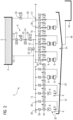
- FIG 1 shows a circuit diagram of a cooling system 2 for cooling a hot-rolled rolling stock (not shown in the figure).
- the cooling system 2 includes a coolant storage 4 designed as a high tank for storing a coolant 6.
- the coolant 6 is water.
- the cooling system 2 includes several cooling beams 8 for applying the coolant 6 to the rolling stock.
- the cooling system 2 has a supply system 9.
- the supply system 9 includes a first main line 10 and a first distribution line 12.
- the first main line 10 is connected directly to the coolant storage 4 on the input side.
- the first main line 10 is connected directly to the first distribution line 12.
- the supply system 9 includes a second main line 14 and a second distribution line 16.
- the second main line 14 is connected directly to the coolant storage 4 on the input side.
- the second main line 14 is connected directly to the second distribution line 16.
- the first and second main lines 10, 14 are connected to one another via a connecting line 18.
- the cooling system 2 includes a coolant pump 20, which is arranged in the second main line 14 and has a frequency-controlled drive.
- the coolant pump 20 is arranged between a first maintenance flap 22 and a second maintenance flap 24, which are arranged in the second main line 14.
- Said maintenance flaps 22, 24 serve to isolate the coolant pump 20 for maintenance and/or repair purposes and thereby be able to service, repair or replace without having to let out the coolant 6.
- a shut-off element 26 designed as a valve for opening and closing the connecting line 18 is arranged in the connecting line 18 between the coolant pump 20 and the second distribution line 16.
- the cooling beams 8 of the cooling system 2 are arranged along a cooling section 30 through which the rolling stock is guided to cool it, the cooling section 30 being divided into a first cooling section section 32 and a second cooling section section 34 in the present exemplary embodiment.
- first and second in conjunction with the term “cooling section” only serve to distinguish the two cooling section sections 32, 34 of the cooling section 30.
- the two cooling section sections 32, 34 can be arranged in such a way that the rolling stock to be cooled (at least at its first pass through the cooling section 30) is guided first through the first cooling section section 32 and then through the second cooling section section 34.
- the two cooling section sections 32, 34 can be arranged in such a way that the rolling stock (at least during its first pass through the cooling section 30) is guided, for example, first through the second cooling section section 34 and then through the first cooling section section 32.
- the cooling system 2 can be designed in such a way that the second cooling section 34 is arranged in front of or behind the first cooling section 32 in the direction of travel of the rolling stock.
- the cooling system 2 includes a plurality of coolant supply lines 36 for supplying the cooling beams 8 with the coolant, with exactly one coolant supply line 36 being provided for each cooling beam 8.
- Each of the cooling beams 8 of the first cooling section 32 is connected to the first distribution line 12 of the supply line system 9 via its own coolant supply line 36.
- each of the cooling beams 8 of the second cooling section 34 is connected to the second distribution line 16 of the supply system 9 via its own coolant supply line 36.
- the cooling beams 8 of the first cooling section 32 are thus supplied with the coolant 6 via the first distribution line 12, whereas the cooling beams 8 of the second cooling section 34 are supplied with the coolant 6 via the second distribution line 16.
- one half of the cooling beams 8 is set up to apply the coolant 6 to the rolling stock to be cooled from above, while the other half of the cooling beams 8 is set up to apply the coolant 6 to the rolling stock to be cooled from below to apply.
- all cooling beams 8 of the second cooling section section 34 are cooling beams of the same design. These cooling beams 8 have nozzles from which the coolant 6 emerges during cooling operation of the cooling system 2.
- the cooling beams 8 of the first cooling section 32 differ from one another in terms of their design. For example, some of the cooling beams 8 of the first cooling section 32 have coolant outlet pipes shaped like a gooseneck. In principle, all cooling beams 8 in the first cooling section 32 could also be of the same design.
- a maintenance flap 38 is arranged in each of the coolant supply lines 36.
- a shut-off element 40 is arranged in each of the coolant supply lines 36, which is designed as a continuously adjustable valve and serves to regulate a coolant flow through the respective coolant supply line 36.
- the cooling system 2 includes a scale channel 42 arranged below the cooling section 30 for collecting the coolant 6 emerging from the cooling beams 8 and for collecting scale particles. Furthermore, the cooling system 2 includes a scale settling tank 44 for depositing scale particles. The scale settling tank 44 is connected to the scale settling tank 42 via a discharge line 46, via which coolant 6 introduced into the scale channel 42 with the scale particles contained therein is passed into the scale settling tank 44.
- cooling system 2 has a bypass line 48 and a shut-off element 50 arranged therein, which is designed as a continuously adjustable valve.
- the bypass line 48 is connected on the input side directly to a connection element 51 of the distribution line 16. On the output side, the bypass line 48 opens into the scale settling tank 44. Furthermore, the shut-off device 50 arranged in the bypass line 48 and the shut-off devices 40 arranged in the coolant supply lines 36 have at least essentially the same switching times.
- the second cooling section section 34 of the cooling system 2 can be operated either in a laminar cooling mode, in a quasi-laminar cooling mode or in an intensive cooling mode.
- the coolant 6 is conducted from the coolant storage 4 via the first main line 10 to the coolant supply lines 36 of the first cooling section 32 and to the coolant supply lines 36 of the second cooling section 34.
- the shut-off device 26 arranged in the connecting line 18 is open, whereas the shut-off device 28 arranged in the second main line 14 is closed.
- the coolant pump 20 is switched off in this cooling mode.
- the coolant 6 is passed from the coolant storage 4 via the first main line 10 to the coolant supply lines 36 of the first cooling section 32 and via the second main line 14 to the coolant supply lines 36 of the second cooling section 34.
- the shut-off device 26 arranged in the connecting line 18 is closed, whereas the shut-off device 28 arranged in the second main line 14 is open.
- the coolant pump 20 is operated at a speed at which a pressure drop in the coolant 6 that occurs when flow through the coolant pump 20 is at least substantially compensated for.
- the coolant pressure in the second main line 14 is increased above the pressure resulting from the coolant storage 4 using the coolant pump 20.
- the coolant is applied to the rolling stock both by cooling beams 8 of the first cooling section 32 and by cooling beams 8 of the second cooling section 34.
- the cooling beams 8 of the first cooling section 32 become always supplied with the coolant 6 via the first main line 10 and not via the second main line 14.
- the coolant supply to the cooling beams 8 is interrupted using the shut-off devices 40 arranged in the coolant supply lines 36.
- the shut-off element 50 arranged in the bypass line 48 releases the bypass line 48.
- the coolant pump 20 is not switched off but is kept in operation in order to avoid the coolant pump 20 starting up again later. If necessary, their speed is reduced in order to reduce the coolant flow through the second main line 14.
- a coolant flow is discharged from the second main line 14 via the bypass line 48, so that the coolant flow bypasses the coolant supply lines 36 of the second cooling section 34. This means that the coolant flow flows into the bypass line 48 instead of flowing into said distribution lines 36. By discharging the coolant flow via the bypass line 48, pressure surges are avoided or at least reduced in the present cooling system 2.
- the coolant flow from the bypass line 48 is not discharged directly from the second main line 14, but rather via the second distribution line 16 connected to the second main line 14. From the bypass line 48, the coolant flow is led directly into the scale settling tank 44.
- the coolant 6 located therein can be conveyed into the coolant storage 4 for reuse either directly or via a coolant treatment system (not shown in the figure).
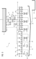
- FIG 2 shows another cooling system 2 for cooling hot-rolled rolling stock.
- bypass line 48 is connected directly to the coolant storage 4 on the output side. Consequently, in the present exemplary embodiment, the coolant flow discharged from the second main line 14 via the bypass line 48 is led from the bypass line 48 directly into the coolant storage 4 (instead of into the scale settling tank 44). Any processing of the coolant introduced into the coolant storage 4 via the bypass line 48 can be omitted here.
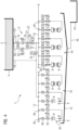
- FIG 3 shows another cooling system 2 for cooling hot-rolled rolling stock.
- bypass line 48 is connected on the input side directly to a connection element 53 of the second main line 14. Accordingly, in the present case, the coolant flow is discharged directly from the second main line 14 via the bypass line 48.
- bypass line 48 is connected directly to the coolant storage 4 on the output side. Consequently, in the present exemplary embodiment, the coolant flow discharged from the second main line 14 via the bypass line 48 is led from the bypass line 48 directly into the coolant storage 4 (instead of into the scale settling tank 44). Any processing of the coolant introduced into the coolant storage 4 via the bypass line 48 can be omitted here.
- FIG 4 shows another cooling system 2 for cooling hot-rolled rolling stock.
- bypass line 48 is connected on the input side directly to a connecting element 53 of the second main line 14. Accordingly, in the present case, the coolant flow is discharged directly from the second main line 14 via the bypass line 48.
- bypass line 48 is connected on the output side to a further connection element 55 of the second main line 14, the first-mentioned connection element 53 of the second main line 14 being arranged downstream of the coolant pump 20 and the further connection element 55 of the second main line 14 being arranged upstream of the coolant pump 20.
- the coolant flow discharged from the second main line 14 via the bypass line 48 is returned from the bypass line 48 directly into the second main line 14 (instead of being led into the scale settling tank 44).
- the shut-off device 50 of the bypass line 48 is open and the shut-off devices 40 of the coolant supply lines 36 of the second cooling section 34 are closed, the coolant flow circulates in the bypass line 48 and in the second main line 14 via the coolant pump 20.
- FIG 5 shows yet another cooling system 2 for cooling hot-rolled rolling stock.
- the cooling system 2 includes an additional bypass line 52 with a shut-off element 54, which is designed as a continuously adjustable valve.
- This bypass line 52 is directly connected to a connection element on the input side 53 of the second main line 14 connected. On the output side, this bypass line 52 is connected directly to the coolant storage 4.
- a further coolant flow is discharged from the second main line 14 via the additional bypass line 52, with the further coolant flow being guided from the additional bypass line 52 directly into the coolant storage 4.
- the shut-off device 50 of the first bypass line 50 is first opened.
- the shut-off device 54 of the additional bypass line 52 is then slowly opened and in return the shut-off device 50 of the first-mentioned bypass line 48 is closed again so that no further coolant is introduced into the scale settling tank 44, since the coolant introduced into the scale settling tank 44 is returned to the coolant storage 4 involves a higher energy expenditure than returning the coolant directly from the second main line 14 into the coolant storage 4.
- bypass line 48 as in FIG 1 be provided.
Landscapes
- Engineering & Computer Science (AREA)
- Chemical & Material Sciences (AREA)
- Mechanical Engineering (AREA)
- Materials Engineering (AREA)
- Thermal Sciences (AREA)
- Crystallography & Structural Chemistry (AREA)
- Physics & Mathematics (AREA)
- Metallurgy (AREA)
- Organic Chemistry (AREA)
- Heat Treatments In General, Especially Conveying And Cooling (AREA)
- Heat Treatment Of Strip Materials And Filament Materials (AREA)
- Metal Rolling (AREA)
- Fluid-Pressure Circuits (AREA)
Claims (13)
- Installation de refroidissement (2) pour le refroidissement d'un produit à laminer, comprenant- plusieurs poutres de refroidissement (8) destinées à l'application d'un agent de refroidissement sur le produit à laminer,- exactement une conduite d'alimentation en agent de refroidissement (36) propre à chacune des poutres de refroidissement (8),- un système d'amenée (9) destiné à l'acheminement de l'agent de refroidissement vers les conduites d'alimentation en agent de refroidissement (36), chacune des poutres de refroidissement (8) étant reliée au système d'amenée (9) par l'intermédiaire de sa propre conduite d'alimentation en agent de refroidissement (36),- une conduite de dérivation (48, 52) destinée à l'évacuation d'un flux d'agent de refroidissement hors du système d'amenée (9), qui est raccordée côté entrée à un élément de raccordement (51, 53) du système d'amenée (9),- un réservoir d'agent de refroidissement (4) auquel le système d'amenée (9) est raccordé,- une goulotte de mâchefer (42),- un bassin de décantation de mâchefer (44) relié à la goulotte de mâchefer (42)- une pompe d'agent de refroidissement (20) permettant d'augmenter la pression d'un agent de refroidissement dans le système d'amenée (9), ainsi que- une conduite de dérivation supplémentaire (48, 52) qui est raccordée côté entrée à un autre élément de raccordement (51, 53) du système d'amenée (9), une des deux conduites de dérivation (48, 52) étant raccordée côté sortie au réservoir d'agent de refroidissement (4) ou en amont de la pompe d'agent de refroidissement (20) à un élément de raccordement supplémentaire (55) du système d'amenée (9) et l'autre des deux conduites de dérivation (48, 52) débouchant côté sortie dans la goulotte de mâchefer (42) ou dans le bassin de décantation de mâchefer (44).
- Installation de refroidissement (2) selon la revendication 1,
caractérisée en ce que le réservoir d'agent de refroidissement (4) est une cuve haute. - Installation de refroidissement (2) selon la revendication 1 ou 2,
caractérisée en ce que la conduite de dérivation (48, 52) est raccordée côté sortie au réservoir d'agent de refroidissement (4). - Installation de refroidissement (2) selon la revendication 1 ou 2,
caractérisée en ce que la conduite de dérivation (48, 52) est raccordée côté sortie à l'élément de raccordement supplémentaire (55) du système d'amenée (9). - Installation de refroidissement (2) selon l'une quelconque des revendications précédentes,
caractérisée en ce que la pompe d'agent de refroidissement (20) étant pourvue d'un entraînement régulé en fréquence. - Installation de refroidissement (2) selon la revendication 1 ou 2,
caractérisée en ce que la conduite de dérivation (48, 52) débouche côté sortie dans la goulotte de mâchefer (42) ou dans le bassin de décantation de mâchefer (44). - Installation de refroidissement (2) selon l'une quelconque des revendications précédentes,
caractérisée par un organe d'arrêt (50, 54) qui est disposé dans la conduite de dérivation (48, 52) et par au moins un organe d'arrêt supplémentaire (40), destinés à interrompre une alimentation en agent de refroidissement vers au moins une des poutres de refroidissement (8). - Installation de refroidissement (2) selon la revendication 7,
caractérisée en ce que l'organe d'arrêt (50, 54) disposé dans la conduite de dérivation (48, 52) et l'organe d'arrêt supplémentaire (40) ont, au moins pour l'essentiel, les mêmes temps de manœuvre. - Installation de refroidissement (2) selon la revendication 7 ou 8,
caractérisée en ce que l'organe d'arrêt supplémentaire (40) est disposé dans le système d'amenée (9) ou dans l'une des conduites d'alimentation en agent de refroidissement (36). - Procédé pour faire fonctionner une installation de refroidissement (2) selon l'une quelconque des revendications précédentes,
caractérisé en ce que- un flux d'agent de refroidissement est évacué hors du système d'amenée (9) par le biais de la conduite de dérivation (48, 52) qui est raccordée côté entrée à l'élément de raccordement (51, 53) du système d'amenée (9),- le flux d'agent de refroidissement est guidé par la conduite de dérivation (48, 52) dans le réservoir d'agent de refroidissement (4) de l'installation de refroidissement (2) ou est ramené en amont de la pompe d'agent de refroidissement (20) dans le système d'amenée (9), et- un flux d'agent de refroidissement supplémentaire est guidé par la conduite de dérivation supplémentaire (48, 52) dans la goulotte de mâchefer (42) ou dans le bassin de décantation de mâchefer (44) de l'installation de refroidissement (2). - Procédé selon la revendication 10,
caractérisé en ce que le flux d'agent de refroidissement est guidé directement de la conduite de dérivation (48, 52) dans le réservoir d'agent de refroidissement (4) de l'installation de refroidissement (2). - Procédé selon la revendication 10,
caractérisé en ce que le flux d'agent de refroidissement est ramené directement de la conduite de dérivation (48, 52) dans le système d'amenée (9), le flux d'agent de refroidissement étant réintroduit dans le système d'amenée (9) en amont d'une pompe d'agent de refroidissement (20) disposée dans le système d'amenée (9). - Procédé selon la revendication 10,
caractérisé en ce que le flux d'agent de refroidissement supplémentaire est guidé directement de la conduite de dérivation supplémentaire (48, 52) dans une goulotte de mâchefer (42) ou dans un bassin de décantation de mâchefer (44) de l'installation de refroidissement (2).
Applications Claiming Priority (2)
| Application Number | Priority Date | Filing Date | Title |
|---|---|---|---|
| EP16204004.2A EP3335812A1 (fr) | 2016-12-14 | 2016-12-14 | Installation de refroidissement de laminés |
| PCT/EP2017/080669 WO2018108518A2 (fr) | 2016-12-14 | 2017-11-28 | Système de refroidissement servant au refroidissement de produits à laminer |
Publications (3)
| Publication Number | Publication Date |
|---|---|
| EP3554727A2 EP3554727A2 (fr) | 2019-10-23 |
| EP3554727B1 EP3554727B1 (fr) | 2020-12-30 |
| EP3554727B2 true EP3554727B2 (fr) | 2024-01-31 |
Family
ID=57569982
Family Applications (2)
| Application Number | Title | Priority Date | Filing Date |
|---|---|---|---|
| EP16204004.2A Withdrawn EP3335812A1 (fr) | 2016-12-14 | 2016-12-14 | Installation de refroidissement de laminés |
| EP17804569.6A Active EP3554727B2 (fr) | 2016-12-14 | 2017-11-28 | Système de refroidissement servant au refroidissement de produits à laminer |
Family Applications Before (1)
| Application Number | Title | Priority Date | Filing Date |
|---|---|---|---|
| EP16204004.2A Withdrawn EP3335812A1 (fr) | 2016-12-14 | 2016-12-14 | Installation de refroidissement de laminés |
Country Status (7)
| Country | Link |
|---|---|
| US (1) | US11103906B2 (fr) |
| EP (2) | EP3335812A1 (fr) |
| JP (1) | JP7210450B2 (fr) |
| CN (1) | CN110049830A (fr) |
| MX (1) | MX2019005854A (fr) |
| RU (1) | RU2755133C2 (fr) |
| WO (1) | WO2018108518A2 (fr) |
Families Citing this family (4)
| Publication number | Priority date | Publication date | Assignee | Title |
|---|---|---|---|---|
| EP3335812A1 (fr) * | 2016-12-14 | 2018-06-20 | Primetals Technologies Austria GmbH | Installation de refroidissement de laminés |
| US20200188975A1 (en) | 2018-12-12 | 2020-06-18 | Primetals Technologies USA LLC | Temperature control system |
| DE102022210057A1 (de) * | 2022-09-23 | 2024-03-28 | Sms Group Gmbh | Verfahren und Computerprogramm zum Betreiben einer Produktionsanlage für ein Metallprodukt |
| DE102022128358A1 (de) * | 2022-10-26 | 2024-05-02 | Sms Group Gmbh | Kühlmodul, Kühlgruppe, Kühlsystem, Verfahren, warmgewalztes metallisches bandförmiges Produkt und Verwendung |
Family Cites Families (15)
| Publication number | Priority date | Publication date | Assignee | Title |
|---|---|---|---|---|
| JPS5256052A (en) * | 1975-11-04 | 1977-05-09 | Hitachi Ltd | Roll coolant device |
| JPS5479817A (en) * | 1977-12-07 | 1979-06-26 | Mitsubishi Heavy Ind Ltd | Water supplying device used pure fluidic control element without movable part |
| SU1224031A1 (ru) | 1983-12-30 | 1986-04-15 | Всесоюзный Научно-Исследовательский И Проектный Институт По Очистке Технологических Газов,Сточных Вод И Использованию Вторичных Энергоресурсов Предприятий Черной Металлургии "Вниипичерметэнергоочистка" | Устройство дл вод ного охлаждени проката и оборудовани стана |
| JPS6267605A (ja) * | 1985-09-20 | 1987-03-27 | Hitachi Ltd | シ−ケンシヤル制御装置 |
| JPS6267605U (fr) * | 1985-10-14 | 1987-04-27 | ||
| SU1703213A1 (ru) | 1989-12-11 | 1992-01-07 | Научно-Производственное Объединение По Защите Атмосферы, Водоемов, Использованию Вторичных Энергоресурсов И Охлаждению Металлургических Агрегатов На Предприятиях Черной Металлургии "Энергосталь" | Устройство дл вод ного охлаждени проката и оборудовани |
| JP5210136B2 (ja) | 2008-12-05 | 2013-06-12 | 株式会社神戸製鋼所 | 条鋼圧延設備の水冷装置における冷却水供給制御方法 |
| CN202192104U (zh) | 2011-07-06 | 2012-04-18 | 安徽精诚铜业股份有限公司 | 一种热轧机的供水电控系统 |
| EP2644718A1 (fr) * | 2012-03-27 | 2013-10-02 | Siemens Aktiengesellschaft | Procédé de stabilisation de pression |
| CN103624093A (zh) | 2012-08-29 | 2014-03-12 | 江苏博际喷雾系统有限公司 | 钢坯中间坯冷却系统 |
| DE102012215599A1 (de) | 2012-09-03 | 2014-03-06 | Sms Siemag Ag | Verfahren und Vorrichtung zur dynamischen Versorgung einer Kühleinrichtung zum Kühlen von Metallband oder sonstigem Walzgut mit Kühlmittel |
| JP6024407B2 (ja) | 2012-11-15 | 2016-11-16 | Jfeスチール株式会社 | 鋼板の冷却装置および冷却方法 |
| CN203750996U (zh) | 2014-01-14 | 2014-08-06 | 中冶南方工程技术有限公司 | 一种热轧棒、线材生产线轧机浊环水供水系统 |
| EP2921239A1 (fr) * | 2014-03-21 | 2015-09-23 | Siemens VAI Metals Technologies GmbH | Refroidissement d'un produit de laminage laminé à chaud |
| EP3335812A1 (fr) * | 2016-12-14 | 2018-06-20 | Primetals Technologies Austria GmbH | Installation de refroidissement de laminés |
-
2016
- 2016-12-14 EP EP16204004.2A patent/EP3335812A1/fr not_active Withdrawn
-
2017
- 2017-11-28 MX MX2019005854A patent/MX2019005854A/es unknown
- 2017-11-28 CN CN201780077797.7A patent/CN110049830A/zh active Pending
- 2017-11-28 RU RU2019120028A patent/RU2755133C2/ru active
- 2017-11-28 WO PCT/EP2017/080669 patent/WO2018108518A2/fr not_active Ceased
- 2017-11-28 EP EP17804569.6A patent/EP3554727B2/fr active Active
- 2017-11-28 US US16/463,432 patent/US11103906B2/en active Active
- 2017-11-28 JP JP2019531754A patent/JP7210450B2/ja active Active
Also Published As
| Publication number | Publication date |
|---|---|
| CN110049830A (zh) | 2019-07-23 |
| EP3335812A1 (fr) | 2018-06-20 |
| JP7210450B2 (ja) | 2023-01-23 |
| EP3554727B1 (fr) | 2020-12-30 |
| WO2018108518A3 (fr) | 2018-11-01 |
| WO2018108518A2 (fr) | 2018-06-21 |
| EP3554727A2 (fr) | 2019-10-23 |
| US11103906B2 (en) | 2021-08-31 |
| RU2019120028A (ru) | 2021-01-15 |
| JP2020513328A (ja) | 2020-05-14 |
| US20200331046A1 (en) | 2020-10-22 |
| RU2755133C2 (ru) | 2021-09-13 |
| RU2019120028A3 (fr) | 2021-05-27 |
| MX2019005854A (es) | 2019-08-12 |
Similar Documents
| Publication | Publication Date | Title |
|---|---|---|
| EP3554727B2 (fr) | Système de refroidissement servant au refroidissement de produits à laminer | |
| EP2892664B1 (fr) | Procédé et dispositif d'alimentation dynamique d'un appareil de refroidissement destiné à refroidir une bande métallique ou un autre produit laminé au moyen d'un réfrigérant | |
| DE102018006965A1 (de) | Schneidflüssigkeitszufuhrvorrichtung für eine Werkzeugmaschine | |
| EP3444038B1 (fr) | Appareil de pulvérisation et procédé de refroidissement d'une barre métallique dans une machine de coulée continue | |
| EP1900449B1 (fr) | Poutre de pulvérisation d'une installation de décalaminage hydraulique et procédé de fonctionnement d'une telle poutre de pulvérisation | |
| EP2841869A1 (fr) | Procédé permettant de fournir un réfrigérant dans un circuit secondaire | |
| DE112004000565B4 (de) | Schalten einer Fluidströmung durch Umleitung | |
| DE102011003194A1 (de) | Rolleneinrichtung | |
| EP2640552A1 (fr) | Dispositif de coupe à jet de suspension d'eau abrasive | |
| DE102004034270B4 (de) | Anlage zum Austragen fließfähiger Fluide, insbesondere von Farben und Lacken und Verfahren zum Betrieb der Anlage | |
| DE19805377A1 (de) | Spritzbalken bei einer hyldraulischen Entzunderungsanlage | |
| DE102013214810B4 (de) | Vorrichtung und Verfahren zur gesteuerten Sekundärkühlung eines gegossenen Metallstrangs | |
| DE102014100839B4 (de) | Wasserabrasiv-Suspensionsschneideeinrichtung, Verfahren zu dessen Steuerung und Computerprogramm | |
| DE102006014572B4 (de) | Vorrichtung und Verfahren zur Luftverteilung in einem Frachtflugzeug | |
| DE102013214809A1 (de) | Vorrichtung und Verfahren zur gesteuerten Mehrstoff-Sekundärkühlung eines gegossenen Metallstrangs | |
| EP3670011B1 (fr) | Refroidissement de la bande métallique dans une cage de laminoir | |
| EP1663572B1 (fr) | Dispositif et procede de lubrification par aerosol par utilisation d'une soupape de derivation | |
| DE10025639A1 (de) | Düsenbalken für die Kühlung oder Entzunderung von metallischem Stranggut, insbesondere von Walzgut | |
| EP1427549B1 (fr) | Rampe de pulverisation concue pour un dispositif de decapage hydraulique | |
| DE2403765A1 (de) | Siebvorrichtung fuer die reinigung schmelzfluessigen kunststoffs | |
| DE2719625A1 (de) | Gichtgasreinigungsanlage | |
| EP0924003B1 (fr) | Dispositif de refroidissement pour refroidir une bande métallique chaude en mouvement | |
| EP0842706A2 (fr) | Installation de revêtement et procédé de commande de l'écoulement du matériau de revêtement dans cette installation | |
| EP4548416A1 (fr) | Système de pile à combustible et procédé de fonctionnement | |
| EP3993917B1 (fr) | Section de refroidissement pourvue de soupapes et de récipients à pression permettant d'éviter les chocs de pression |
Legal Events
| Date | Code | Title | Description |
|---|---|---|---|
| STAA | Information on the status of an ep patent application or granted ep patent |
Free format text: STATUS: UNKNOWN |
|
| STAA | Information on the status of an ep patent application or granted ep patent |
Free format text: STATUS: THE INTERNATIONAL PUBLICATION HAS BEEN MADE |
|
| PUAI | Public reference made under article 153(3) epc to a published international application that has entered the european phase |
Free format text: ORIGINAL CODE: 0009012 |
|
| STAA | Information on the status of an ep patent application or granted ep patent |
Free format text: STATUS: REQUEST FOR EXAMINATION WAS MADE |
|
| 17P | Request for examination filed |
Effective date: 20190715 |
|
| AK | Designated contracting states |
Kind code of ref document: A2 Designated state(s): AL AT BE BG CH CY CZ DE DK EE ES FI FR GB GR HR HU IE IS IT LI LT LU LV MC MK MT NL NO PL PT RO RS SE SI SK SM TR |
|
| AX | Request for extension of the european patent |
Extension state: BA ME |
|
| DAV | Request for validation of the european patent (deleted) | ||
| DAX | Request for extension of the european patent (deleted) | ||
| GRAP | Despatch of communication of intention to grant a patent |
Free format text: ORIGINAL CODE: EPIDOSNIGR1 |
|
| STAA | Information on the status of an ep patent application or granted ep patent |
Free format text: STATUS: GRANT OF PATENT IS INTENDED |
|
| INTG | Intention to grant announced |
Effective date: 20200818 |
|
| GRAS | Grant fee paid |
Free format text: ORIGINAL CODE: EPIDOSNIGR3 |
|
| GRAA | (expected) grant |
Free format text: ORIGINAL CODE: 0009210 |
|
| STAA | Information on the status of an ep patent application or granted ep patent |
Free format text: STATUS: THE PATENT HAS BEEN GRANTED |
|
| AK | Designated contracting states |
Kind code of ref document: B1 Designated state(s): AL AT BE BG CH CY CZ DE DK EE ES FI FR GB GR HR HU IE IS IT LI LT LU LV MC MK MT NL NO PL PT RO RS SE SI SK SM TR |
|
| REG | Reference to a national code |
Ref country code: GB Ref legal event code: FG4D Free format text: NOT ENGLISH |
|
| REG | Reference to a national code |
Ref country code: AT Ref legal event code: REF Ref document number: 1349415 Country of ref document: AT Kind code of ref document: T Effective date: 20210115 |
|
| REG | Reference to a national code |
Ref country code: DE Ref legal event code: R096 Ref document number: 502017008890 Country of ref document: DE |
|
| REG | Reference to a national code |
Ref country code: IE Ref legal event code: FG4D Free format text: LANGUAGE OF EP DOCUMENT: GERMAN |
|
| PG25 | Lapsed in a contracting state [announced via postgrant information from national office to epo] |
Ref country code: RS Free format text: LAPSE BECAUSE OF FAILURE TO SUBMIT A TRANSLATION OF THE DESCRIPTION OR TO PAY THE FEE WITHIN THE PRESCRIBED TIME-LIMIT Effective date: 20201230 Ref country code: FI Free format text: LAPSE BECAUSE OF FAILURE TO SUBMIT A TRANSLATION OF THE DESCRIPTION OR TO PAY THE FEE WITHIN THE PRESCRIBED TIME-LIMIT Effective date: 20201230 Ref country code: GR Free format text: LAPSE BECAUSE OF FAILURE TO SUBMIT A TRANSLATION OF THE DESCRIPTION OR TO PAY THE FEE WITHIN THE PRESCRIBED TIME-LIMIT Effective date: 20210331 Ref country code: NO Free format text: LAPSE BECAUSE OF FAILURE TO SUBMIT A TRANSLATION OF THE DESCRIPTION OR TO PAY THE FEE WITHIN THE PRESCRIBED TIME-LIMIT Effective date: 20210330 |
|
| PG25 | Lapsed in a contracting state [announced via postgrant information from national office to epo] |
Ref country code: LV Free format text: LAPSE BECAUSE OF FAILURE TO SUBMIT A TRANSLATION OF THE DESCRIPTION OR TO PAY THE FEE WITHIN THE PRESCRIBED TIME-LIMIT Effective date: 20201230 Ref country code: SE Free format text: LAPSE BECAUSE OF FAILURE TO SUBMIT A TRANSLATION OF THE DESCRIPTION OR TO PAY THE FEE WITHIN THE PRESCRIBED TIME-LIMIT Effective date: 20201230 Ref country code: BG Free format text: LAPSE BECAUSE OF FAILURE TO SUBMIT A TRANSLATION OF THE DESCRIPTION OR TO PAY THE FEE WITHIN THE PRESCRIBED TIME-LIMIT Effective date: 20210330 |
|
| REG | Reference to a national code |
Ref country code: NL Ref legal event code: MP Effective date: 20201230 |
|
| PG25 | Lapsed in a contracting state [announced via postgrant information from national office to epo] |
Ref country code: HR Free format text: LAPSE BECAUSE OF FAILURE TO SUBMIT A TRANSLATION OF THE DESCRIPTION OR TO PAY THE FEE WITHIN THE PRESCRIBED TIME-LIMIT Effective date: 20201230 |
|
| REG | Reference to a national code |
Ref country code: LT Ref legal event code: MG9D |
|
| PG25 | Lapsed in a contracting state [announced via postgrant information from national office to epo] |
Ref country code: SK Free format text: LAPSE BECAUSE OF FAILURE TO SUBMIT A TRANSLATION OF THE DESCRIPTION OR TO PAY THE FEE WITHIN THE PRESCRIBED TIME-LIMIT Effective date: 20201230 Ref country code: PT Free format text: LAPSE BECAUSE OF FAILURE TO SUBMIT A TRANSLATION OF THE DESCRIPTION OR TO PAY THE FEE WITHIN THE PRESCRIBED TIME-LIMIT Effective date: 20210430 Ref country code: RO Free format text: LAPSE BECAUSE OF FAILURE TO SUBMIT A TRANSLATION OF THE DESCRIPTION OR TO PAY THE FEE WITHIN THE PRESCRIBED TIME-LIMIT Effective date: 20201230 Ref country code: EE Free format text: LAPSE BECAUSE OF FAILURE TO SUBMIT A TRANSLATION OF THE DESCRIPTION OR TO PAY THE FEE WITHIN THE PRESCRIBED TIME-LIMIT Effective date: 20201230 Ref country code: CZ Free format text: LAPSE BECAUSE OF FAILURE TO SUBMIT A TRANSLATION OF THE DESCRIPTION OR TO PAY THE FEE WITHIN THE PRESCRIBED TIME-LIMIT Effective date: 20201230 Ref country code: LT Free format text: LAPSE BECAUSE OF FAILURE TO SUBMIT A TRANSLATION OF THE DESCRIPTION OR TO PAY THE FEE WITHIN THE PRESCRIBED TIME-LIMIT Effective date: 20201230 |
|
| PG25 | Lapsed in a contracting state [announced via postgrant information from national office to epo] |
Ref country code: PL Free format text: LAPSE BECAUSE OF FAILURE TO SUBMIT A TRANSLATION OF THE DESCRIPTION OR TO PAY THE FEE WITHIN THE PRESCRIBED TIME-LIMIT Effective date: 20201230 |
|
| PG25 | Lapsed in a contracting state [announced via postgrant information from national office to epo] |
Ref country code: IS Free format text: LAPSE BECAUSE OF FAILURE TO SUBMIT A TRANSLATION OF THE DESCRIPTION OR TO PAY THE FEE WITHIN THE PRESCRIBED TIME-LIMIT Effective date: 20210430 |
|
| REG | Reference to a national code |
Ref country code: DE Ref legal event code: R026 Ref document number: 502017008890 Country of ref document: DE |
|
| PLBI | Opposition filed |
Free format text: ORIGINAL CODE: 0009260 |
|
| PLAX | Notice of opposition and request to file observation + time limit sent |
Free format text: ORIGINAL CODE: EPIDOSNOBS2 |
|
| PG25 | Lapsed in a contracting state [announced via postgrant information from national office to epo] |
Ref country code: AL Free format text: LAPSE BECAUSE OF FAILURE TO SUBMIT A TRANSLATION OF THE DESCRIPTION OR TO PAY THE FEE WITHIN THE PRESCRIBED TIME-LIMIT Effective date: 20201230 |
|
| 26 | Opposition filed |
Opponent name: SMS GROUP GMBH Effective date: 20210930 |
|
| PG25 | Lapsed in a contracting state [announced via postgrant information from national office to epo] |
Ref country code: DK Free format text: LAPSE BECAUSE OF FAILURE TO SUBMIT A TRANSLATION OF THE DESCRIPTION OR TO PAY THE FEE WITHIN THE PRESCRIBED TIME-LIMIT Effective date: 20201230 |
|
| PG25 | Lapsed in a contracting state [announced via postgrant information from national office to epo] |
Ref country code: ES Free format text: LAPSE BECAUSE OF FAILURE TO SUBMIT A TRANSLATION OF THE DESCRIPTION OR TO PAY THE FEE WITHIN THE PRESCRIBED TIME-LIMIT Effective date: 20201230 |
|
| PLBB | Reply of patent proprietor to notice(s) of opposition received |
Free format text: ORIGINAL CODE: EPIDOSNOBS3 |
|
| PG25 | Lapsed in a contracting state [announced via postgrant information from national office to epo] |
Ref country code: SI Free format text: LAPSE BECAUSE OF FAILURE TO SUBMIT A TRANSLATION OF THE DESCRIPTION OR TO PAY THE FEE WITHIN THE PRESCRIBED TIME-LIMIT Effective date: 20201230 |
|
| PG25 | Lapsed in a contracting state [announced via postgrant information from national office to epo] |
Ref country code: IS Free format text: LAPSE BECAUSE OF FAILURE TO SUBMIT A TRANSLATION OF THE DESCRIPTION OR TO PAY THE FEE WITHIN THE PRESCRIBED TIME-LIMIT Effective date: 20210430 |
|
| PG25 | Lapsed in a contracting state [announced via postgrant information from national office to epo] |
Ref country code: MC Free format text: LAPSE BECAUSE OF FAILURE TO SUBMIT A TRANSLATION OF THE DESCRIPTION OR TO PAY THE FEE WITHIN THE PRESCRIBED TIME-LIMIT Effective date: 20201230 |
|
| REG | Reference to a national code |
Ref country code: CH Ref legal event code: PL |
|
| GBPC | Gb: european patent ceased through non-payment of renewal fee |
Effective date: 20211128 |
|
| PG25 | Lapsed in a contracting state [announced via postgrant information from national office to epo] |
Ref country code: LU Free format text: LAPSE BECAUSE OF NON-PAYMENT OF DUE FEES Effective date: 20211128 Ref country code: BE Free format text: LAPSE BECAUSE OF NON-PAYMENT OF DUE FEES Effective date: 20211130 |
|
| REG | Reference to a national code |
Ref country code: BE Ref legal event code: MM Effective date: 20211130 |
|
| PG25 | Lapsed in a contracting state [announced via postgrant information from national office to epo] |
Ref country code: LI Free format text: LAPSE BECAUSE OF NON-PAYMENT OF DUE FEES Effective date: 20211130 Ref country code: CH Free format text: LAPSE BECAUSE OF NON-PAYMENT OF DUE FEES Effective date: 20211130 |
|
| PG25 | Lapsed in a contracting state [announced via postgrant information from national office to epo] |
Ref country code: IE Free format text: LAPSE BECAUSE OF NON-PAYMENT OF DUE FEES Effective date: 20211128 Ref country code: GB Free format text: LAPSE BECAUSE OF NON-PAYMENT OF DUE FEES Effective date: 20211128 |
|
| PG25 | Lapsed in a contracting state [announced via postgrant information from national office to epo] |
Ref country code: FR Free format text: LAPSE BECAUSE OF NON-PAYMENT OF DUE FEES Effective date: 20211130 |
|
| PG25 | Lapsed in a contracting state [announced via postgrant information from national office to epo] |
Ref country code: NL Free format text: LAPSE BECAUSE OF NON-PAYMENT OF DUE FEES Effective date: 20201230 Ref country code: CY Free format text: LAPSE BECAUSE OF FAILURE TO SUBMIT A TRANSLATION OF THE DESCRIPTION OR TO PAY THE FEE WITHIN THE PRESCRIBED TIME-LIMIT Effective date: 20201230 |
|
| P01 | Opt-out of the competence of the unified patent court (upc) registered |
Effective date: 20230614 |
|
| PG25 | Lapsed in a contracting state [announced via postgrant information from national office to epo] |
Ref country code: SM Free format text: LAPSE BECAUSE OF FAILURE TO SUBMIT A TRANSLATION OF THE DESCRIPTION OR TO PAY THE FEE WITHIN THE PRESCRIBED TIME-LIMIT Effective date: 20201230 Ref country code: HU Free format text: LAPSE BECAUSE OF FAILURE TO SUBMIT A TRANSLATION OF THE DESCRIPTION OR TO PAY THE FEE WITHIN THE PRESCRIBED TIME-LIMIT; INVALID AB INITIO Effective date: 20171128 |
|
| PUAH | Patent maintained in amended form |
Free format text: ORIGINAL CODE: 0009272 |
|
| STAA | Information on the status of an ep patent application or granted ep patent |
Free format text: STATUS: PATENT MAINTAINED AS AMENDED |
|
| 27A | Patent maintained in amended form |
Effective date: 20240131 |
|
| AK | Designated contracting states |
Kind code of ref document: B2 Designated state(s): AL AT BE BG CH CY CZ DE DK EE ES FI FR GB GR HR HU IE IS IT LI LT LU LV MC MK MT NL NO PL PT RO RS SE SI SK SM TR |
|
| REG | Reference to a national code |
Ref country code: DE Ref legal event code: R102 Ref document number: 502017008890 Country of ref document: DE |
|
| PG25 | Lapsed in a contracting state [announced via postgrant information from national office to epo] |
Ref country code: MK Free format text: LAPSE BECAUSE OF FAILURE TO SUBMIT A TRANSLATION OF THE DESCRIPTION OR TO PAY THE FEE WITHIN THE PRESCRIBED TIME-LIMIT Effective date: 20201230 |
|
| PG25 | Lapsed in a contracting state [announced via postgrant information from national office to epo] |
Ref country code: MT Free format text: LAPSE BECAUSE OF FAILURE TO SUBMIT A TRANSLATION OF THE DESCRIPTION OR TO PAY THE FEE WITHIN THE PRESCRIBED TIME-LIMIT Effective date: 20201230 |
|
| REG | Reference to a national code |
Ref country code: DE Ref legal event code: R082 Ref document number: 502017008890 Country of ref document: DE Representative=s name: LINDNER BLAUMEIER, PATENT- UND RECHTSANWAELTE,, DE |
|
| PGFP | Annual fee paid to national office [announced via postgrant information from national office to epo] |
Ref country code: DE Payment date: 20251119 Year of fee payment: 9 |
|
| PGFP | Annual fee paid to national office [announced via postgrant information from national office to epo] |
Ref country code: AT Payment date: 20251120 Year of fee payment: 9 |
|
| PGFP | Annual fee paid to national office [announced via postgrant information from national office to epo] |
Ref country code: IT Payment date: 20251125 Year of fee payment: 9 |
|
| PGFP | Annual fee paid to national office [announced via postgrant information from national office to epo] |
Ref country code: TR Payment date: 20251124 Year of fee payment: 9 |