EP3554727B2 - Cooling system for cooling rolling stock - Google Patents
Cooling system for cooling rolling stock Download PDFInfo
- Publication number
- EP3554727B2 EP3554727B2 EP17804569.6A EP17804569A EP3554727B2 EP 3554727 B2 EP3554727 B2 EP 3554727B2 EP 17804569 A EP17804569 A EP 17804569A EP 3554727 B2 EP3554727 B2 EP 3554727B2
- Authority
- EP
- European Patent Office
- Prior art keywords
- coolant
- cooling
- line
- bypass line
- cooling system
- Prior art date
- Legal status (The legal status is an assumption and is not a legal conclusion. Google has not performed a legal analysis and makes no representation as to the accuracy of the status listed.)
- Active
Links
Images


Classifications
-
- B—PERFORMING OPERATIONS; TRANSPORTING
- B21—MECHANICAL METAL-WORKING WITHOUT ESSENTIALLY REMOVING MATERIAL; PUNCHING METAL
- B21B—ROLLING OF METAL
- B21B45/00—Devices for surface or other treatment of work, specially combined with or arranged in, or specially adapted for use in connection with, metal-rolling mills
- B21B45/02—Devices for surface or other treatment of work, specially combined with or arranged in, or specially adapted for use in connection with, metal-rolling mills for lubricating, cooling, or cleaning
- B21B45/0203—Cooling
- B21B45/0209—Cooling devices, e.g. using gaseous coolants
- B21B45/0215—Cooling devices, e.g. using gaseous coolants using liquid coolants, e.g. for sections, for tubes
- B21B45/0218—Cooling devices, e.g. using gaseous coolants using liquid coolants, e.g. for sections, for tubes for strips, sheets, or plates
-
- B—PERFORMING OPERATIONS; TRANSPORTING
- B21—MECHANICAL METAL-WORKING WITHOUT ESSENTIALLY REMOVING MATERIAL; PUNCHING METAL
- B21B—ROLLING OF METAL
- B21B37/00—Control devices or methods specially adapted for metal-rolling mills or the work produced thereby
- B21B37/74—Temperature control, e.g. by cooling or heating the rolls or the product
-
- B—PERFORMING OPERATIONS; TRANSPORTING
- B21—MECHANICAL METAL-WORKING WITHOUT ESSENTIALLY REMOVING MATERIAL; PUNCHING METAL
- B21B—ROLLING OF METAL
- B21B45/00—Devices for surface or other treatment of work, specially combined with or arranged in, or specially adapted for use in connection with, metal-rolling mills
- B21B45/02—Devices for surface or other treatment of work, specially combined with or arranged in, or specially adapted for use in connection with, metal-rolling mills for lubricating, cooling, or cleaning
-
- C—CHEMISTRY; METALLURGY
- C21—METALLURGY OF IRON
- C21D—MODIFYING THE PHYSICAL STRUCTURE OF FERROUS METALS; GENERAL DEVICES FOR HEAT TREATMENT OF FERROUS OR NON-FERROUS METALS OR ALLOYS; MAKING METAL MALLEABLE, e.g. BY DECARBURISATION OR TEMPERING
- C21D1/00—General methods or devices for heat treatment, e.g. annealing, hardening, quenching or tempering
- C21D1/62—Quenching devices
- C21D1/667—Quenching devices for spray quenching
Definitions
- the invention relates to a cooling system for cooling rolling stock, which comprises a plurality of cooling beams for applying a coolant to the rolling stock, exactly one coolant supply line for each of the cooling beams and a feed system for guiding the coolant to the coolant supply lines, each of the cooling beams having its own coolant supply line connected to the supply system.
- Such a cooling system is used to achieve a defined cooling of rolling stock.
- the rolling stock is fed to the cooling system.
- a coolant usually water, is then applied to the rolling stock.
- a defined cooling of the rolling stock is of central importance in order to achieve the desired material properties of the rolling stock, such as a desired microstructure.
- the coolant supply to the cooling beams is usually interrupted.
- One or more shut-off devices of the cooling system are typically used to interrupt the coolant supply.
- One object of the invention is to provide an improved cooling system for cooling rolled stock.
- the cooling system according to the invention comprises several cooling beams for applying a coolant to the rolling stock.
- the cooling system includes exactly one coolant supply line for each of the cooling beams. This means that the cooling system has several coolant supply lines, with exactly one coolant supply line being provided for each of the cooling beams.
- the cooling system includes a supply system for guiding the coolant to the coolant supply lines.
- each of the cooling beams is connected to the supply system via its own coolant supply line.
- each of the cooling beams is connected to the supply line system via exactly one coolant supply line that is assigned to the respective cooling beam or is intended for it.
- the cooling system has a bypass line for discharging a coolant flow from the supply line system, which is connected on the input side to a connection element, in particular a connection piece, of the supply line system.
- the cooling system has a coolant storage to which the supply line system is connected, a scale trough, a scale settling tank connected to the scale trough and a further bypass line, which is connected on the input side to another connection element of the supply line system, one of the two bypass lines being connected to the coolant storage on the output side or is connected to a further connection element of the supply line system and the other of the two bypass lines opens into the scale channel or into the scale settling basin on the output side.
- the invention is based on the idea that if the coolant supply is quickly interrupted, pressure surges can occur in the cooling system, in particular in its lines, which can, under certain circumstances, damage components of the cooling system and possibly lead to a failure of the cooling system.
- the occurrence of pressure surges, which can damage the cooling system is particularly problematic when the cooling system is operated in the so-called intensive cooling mode, since in this mode there are usually higher coolant pressures in the lines of the cooling system than when the cooling system is operated in the so-called laminar cooling mode.
- the invention allows the coolant to flow out of the supply system via the bypass line if the coolant supply to the cooling beams is interrupted.
- the bypass line therefore provides the coolant with an alternative flow path. In this way, pressure surges in the cooling system can be avoided or at least reduced when the coolant supply to the cooling beams is interrupted. This in turn means that components of the cooling system can be protected and their service life can be increased.
- the bypass line is expediently released if the coolant supply to the cooling beams is interrupted.
- bypass line is connected to a connection element of the supply line system, several cooling beams can be bridged at once via the bypass line, i.e. several cooling beams with the same bypass line.
- a separate bypass line for each of the coolant supply lines - and possibly a separate shut-off device for each such bypass line - is therefore not required. This enables a structurally simple and cost-effective design of the cooling system. In addition, this enables simple control technology operation of the cooling system.
- the line can be used in particular a pipe, a pipe section or a system of interconnected pipes can be understood.
- connection can be understood as a shortened form of the expression “fluid-technically connected”.
- An element of the cooling system can be considered to be connected to another element of the cooling system if a fluid, in particular the aforementioned coolant, can flow from one of the two elements to the other of the two elements.
- Applying the coolant to the rolling stock can be understood to mean applying the coolant to a surface of the rolling stock.
- the coolant can be applied to the rolling stock from one or more sides.
- the coolant is preferably applied to the rolling stock from above and below.
- the bypass line is preferably connected directly to the connection element of the supply line system. This means that the bypass line can be connected directly to the supply system.
- the respective coolant supply line (on the output side) is expediently connected directly to the cooling beam assigned to it.
- a coolant supply line can be understood as a line that supplies exactly one of the cooling beams with the coolant. It is further preferred if the respective cooling beam is connected to the supply system exclusively via its own coolant supply line. Preferably, the respective coolant supply line (on the input side) is directly connected to the supply line system.
- the supply system can include one or more lines.
- the supply system comprises at least one main line and at least one distribution line.
- the main line is expediently connected directly or indirectly to the distribution line on the output side.
- the coolant supply lines are connected directly or indirectly to the distribution line on the input side.
- the respective coolant supply line is advantageously connected directly to the cooling beam assigned to it.
- the cooling system advantageously comprises a coolant pump for increasing a coolant pressure in the supply system. It is expedient if the coolant pump is arranged in the aforementioned main line.
- the wording that the coolant pump is expediently arranged in the main line is not necessarily to be understood as meaning that the coolant pump is enclosed by the main line in such an arrangement.
- the main line can have a first line section that is connected to an inlet of the coolant pump.
- the main line can have a second line section that is connected to an output of the coolant pump.
- the coolant pump can be used to control the cooling capacity of the cooling system.
- other elements of the cooling system such as one or more control valves, can be used to control the cooling capacity.
- bypass line makes it possible to keep the coolant moving in the cooling system by providing an alternative flow path when the coolant supply to the cooling beams is interrupted, it is not necessary to switch off the coolant pump when the coolant supply is interrupted. Rather, even if the coolant supply to the cooling beams is interrupted, a predetermined minimum volume flow of coolant, which is conveyed by the coolant pump, can be ensured.
- the coolant pump is preferably equipped with a frequency-controlled drive. With such a pump, the coolant volume flow delivered by the pump can be precisely adjusted.
- a coolant pump with a frequency-controlled drive can be understood as a pump in which its speed serves as a controlled variable.
- the cooling system can have several coolant pumps, in particular several coolant pumps of the type described above.
- a preferred development of the invention provides that the cooling system has a high tank for storing the coolant.
- the feed system in particular its main line, is preferably connected on the input side directly to the coolant storage or to a connection element of the coolant storage.
- the coolant can be drained from the coolant storage via the supply system.
- connection element of the feed system can be an element of the main line or the distribution line.
- the bypass line can be connected on the input side, in particular to the main line or the distribution line of the supply system.
- the bypass line is expediently connected to the main line on the input side downstream of the aforementioned coolant pump.
- the bypass line is connected to the coolant storage on the output side, in particular connected directly to the coolant storage. This allows the coolant flow to be (returned) to the coolant storage. This in turn means that less coolant has to be introduced into the coolant reservoir in other ways in order to refill it, which means energy can be saved.
- bypass line is connected on the output side to a further connection element of the supply line system, in particular is connected directly to the further connection element. This allows the coolant flow to be (returned) into the supply system. This also means that less coolant has to be introduced into the coolant storage by other means in order to refill it, which means energy can be saved.
- the cooling system is expediently equipped with an additional connection element, which is arranged upstream of the aforementioned coolant pump.
- a preferred embodiment of the invention provides that the bypass line is connected on the output side to the additional connection element, in particular is connected directly.
- This additional connection element can be, for example, the further connection element of the supply line system mentioned above or a connection element of the coolant storage.
- a fluid introduced into the scale trough, in particular the coolant, can expediently flow out of the scale trough into the scale settling tank.
- the bypass line opens into the scale channel or into the scale settling basin on the output side.
- the bypass line does not necessarily have to be connected to the scale trough or the scale settling tank.
- the formulation that "the bypass line opens into the scale trough or into the scale settling tank on the output side" can be understood to mean that the outlet of the bypass line is arranged in such a way that the coolant flow can flow out of the bypass line into the scale trough or into the scale settling tank.
- the outlet of the bypass line can be arranged above the scale trough or the scale settling tank.
- the coolant contained therein can be (returned) from the scale settling tank, if necessary after it has passed through a processing plant, into said coolant storage and/or into the supply system.
- the further bypass line is expediently connected directly to the other connection element on the input side.
- the cooling system has a shut-off device, in particular a valve, which is arranged in the bypass line. Furthermore, it is expedient if the cooling system has at least one further shut-off device, in particular a valve, for interrupting a coolant supply to at least one of the cooling beams.
- the shut-off device arranged in the bypass line and the further shut-off device advantageously have at least essentially the same switching times. In this way, the opening of the bypass line can be carried out synchronously with the interruption of the coolant supply to the cooling beams. Conversely, the closing of the bypass line can be carried out synchronously with the (re-)release of the coolant supply to the cooling beams.
- the switching time of a shut-off device can be understood as the time that the shut-off device needs (after issuing a blocking or unlocking command) to completely close or completely close a line cross-section of the line in which the shut-off device is arranged from a completely open state. to completely open the cable cross section from a completely closed state.
- the further shut-off element is preferably arranged in the feed system, in particular in the aforementioned main line of the feed system, or in one of the coolant supply lines.
- the cooling system can have several shut-off devices, each of which is set up to interrupt a coolant supply to at least one of the cooling beams.
- a common shut-off device can be provided for several of the cooling beams.
- a separate shut-off device can be provided for each of the cooling beams.
- a shut-off device can be arranged in each of the coolant supply lines.
- An additional shut-off device in particular a valve, is expediently arranged in the further bypass line.
- the additional shut-off device arranged in the further bypass line can be designed identically to the shut-off device arranged in the first-mentioned bypass line.
- the additional shut-off device can have the same switching time as the shut-off device arranged in the first-mentioned bypass line.
- the shut-off devices can expediently be controlled or actuated using a control device.
- the respective shut-off device can in particular be actuated electrically, pneumatically and/or hydraulically.
- the respective shut-off element can not only be completely opened and completely closed, but can also assume intermediate positions, in particular continuous intermediate positions, between these two states. In other words, the shut-off devices can be continuously adjustable.
- At least one of the bypass lines can comprise several line sections which are connected in parallel to one another.
- the line sections connected in parallel to one another expediently open on the input side into a common line section of the respective bypass line.
- a shut-off device in particular a valve, can be arranged in each of the individual line sections connected in parallel to one another.
- the invention further relates to a method for operating a cooling system.
- the cooling system mentioned in connection with the method is the cooling system according to the invention, in particular one of its advantageous developments described above. Furthermore, the material elements mentioned in connection with the method can be the elements already mentioned above.
- a coolant flow is discharged from the supply line system via a bypass line, which is connected on the input side to a connection element of the supply line system.
- the first-mentioned coolant flow is guided via the first-mentioned bypass line into the coolant storage of the cooling system or returned into the supply system, in particular led directly into the coolant storage or returned directly into the supply system.
- the further coolant flow is advantageously guided via the further bypass line into the scale trough or into the scale settling basin of the cooling system, in particular directly into the scale trough or directly into the scale settling basin of the cooling system.
- the coolant flow is expediently discharged from the supply system via the bypass line.
- the coolant flow which is discharged from the supply line system via the bypass line, can be a partial flow of a total coolant flow flowing through the supply system or of said total coolant flow.
- the coolant flow is discharged from the supply system via the bypass line in such a way that the coolant flow bypasses the coolant supply lines.
- the coolant flow is preferably guided via the bypass line in such a way that the coolant flow, instead of flowing into the supply lines, flows somewhere else, for example into another element of the cooling system or out of the cooling system.
- the coolant flow can be guided from the bypass line, for example, into a coolant inlet of the cooling system, which is positioned upstream of a coolant pump arranged in the supply line system.
- the coolant flow is led from the bypass line directly into the coolant storage. Since there is normally no contamination of the coolant, there is no need to process the coolant, so that there is no energy requirement for processing the coolant fed into the coolant storage.
- the coolant flow from the bypass line is returned directly to the supply line system.
- the coolant flow is expediently reintroduced into the supply system upstream of a coolant pump arranged in the supply system.
- the coolant flow can in particular be returned from the bypass line into the supply line system in front of an inlet of the coolant pump.
- An advantageous variant of the invention provides that the further coolant flow from the further bypass line is led directly into the scale channel or into the scale settling tank.
- the coolant located in the scale trough is preferably forwarded from the scale trough into the scale settling tank.
- the coolant contained therein can also be (returned) from the scale settling tank into the coolant storage and/or into the supply system. Before the coolant located in the scale settling tank is (returned) to the coolant storage and/or into the supply system, it can optionally be processed in a processing plant, in particular cleaned of foreign bodies.
- the coolant flow is preferably discharged downstream of the coolant pump, in particular between the coolant pump and the coolant supply lines, via the bypass line from the supply system.
- FIG 1 to FIG 4 are exemplary embodiments not according to the invention, which serve to explain individual features
- Figure 5 represents an exemplary embodiment according to the invention.
- the exemplary embodiments serve to explain the invention and do not limit the invention to the combinations of features specified therein, not even with regard to functional features.
- suitable features of each exemplary embodiment can also be explicitly considered in isolation, removed from one exemplary embodiment, introduced into another exemplary embodiment to supplement it and combined with any of the claims.
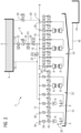
- FIG 1 shows a circuit diagram of a cooling system 2 for cooling a hot-rolled rolling stock (not shown in the figure).
- the cooling system 2 includes a coolant storage 4 designed as a high tank for storing a coolant 6.
- the coolant 6 is water.
- the cooling system 2 includes several cooling beams 8 for applying the coolant 6 to the rolling stock.
- the cooling system 2 has a supply system 9.
- the supply system 9 includes a first main line 10 and a first distribution line 12.
- the first main line 10 is connected directly to the coolant storage 4 on the input side.
- the first main line 10 is connected directly to the first distribution line 12.
- the supply system 9 includes a second main line 14 and a second distribution line 16.
- the second main line 14 is connected directly to the coolant storage 4 on the input side.
- the second main line 14 is connected directly to the second distribution line 16.
- the first and second main lines 10, 14 are connected to one another via a connecting line 18.
- the cooling system 2 includes a coolant pump 20, which is arranged in the second main line 14 and has a frequency-controlled drive.
- the coolant pump 20 is arranged between a first maintenance flap 22 and a second maintenance flap 24, which are arranged in the second main line 14.
- Said maintenance flaps 22, 24 serve to isolate the coolant pump 20 for maintenance and/or repair purposes and thereby be able to service, repair or replace without having to let out the coolant 6.
- a shut-off element 26 designed as a valve for opening and closing the connecting line 18 is arranged in the connecting line 18 between the coolant pump 20 and the second distribution line 16.
- the cooling beams 8 of the cooling system 2 are arranged along a cooling section 30 through which the rolling stock is guided to cool it, the cooling section 30 being divided into a first cooling section section 32 and a second cooling section section 34 in the present exemplary embodiment.
- first and second in conjunction with the term “cooling section” only serve to distinguish the two cooling section sections 32, 34 of the cooling section 30.
- the two cooling section sections 32, 34 can be arranged in such a way that the rolling stock to be cooled (at least at its first pass through the cooling section 30) is guided first through the first cooling section section 32 and then through the second cooling section section 34.
- the two cooling section sections 32, 34 can be arranged in such a way that the rolling stock (at least during its first pass through the cooling section 30) is guided, for example, first through the second cooling section section 34 and then through the first cooling section section 32.
- the cooling system 2 can be designed in such a way that the second cooling section 34 is arranged in front of or behind the first cooling section 32 in the direction of travel of the rolling stock.
- the cooling system 2 includes a plurality of coolant supply lines 36 for supplying the cooling beams 8 with the coolant, with exactly one coolant supply line 36 being provided for each cooling beam 8.
- Each of the cooling beams 8 of the first cooling section 32 is connected to the first distribution line 12 of the supply line system 9 via its own coolant supply line 36.
- each of the cooling beams 8 of the second cooling section 34 is connected to the second distribution line 16 of the supply system 9 via its own coolant supply line 36.
- the cooling beams 8 of the first cooling section 32 are thus supplied with the coolant 6 via the first distribution line 12, whereas the cooling beams 8 of the second cooling section 34 are supplied with the coolant 6 via the second distribution line 16.
- one half of the cooling beams 8 is set up to apply the coolant 6 to the rolling stock to be cooled from above, while the other half of the cooling beams 8 is set up to apply the coolant 6 to the rolling stock to be cooled from below to apply.
- all cooling beams 8 of the second cooling section section 34 are cooling beams of the same design. These cooling beams 8 have nozzles from which the coolant 6 emerges during cooling operation of the cooling system 2.
- the cooling beams 8 of the first cooling section 32 differ from one another in terms of their design. For example, some of the cooling beams 8 of the first cooling section 32 have coolant outlet pipes shaped like a gooseneck. In principle, all cooling beams 8 in the first cooling section 32 could also be of the same design.
- a maintenance flap 38 is arranged in each of the coolant supply lines 36.
- a shut-off element 40 is arranged in each of the coolant supply lines 36, which is designed as a continuously adjustable valve and serves to regulate a coolant flow through the respective coolant supply line 36.
- the cooling system 2 includes a scale channel 42 arranged below the cooling section 30 for collecting the coolant 6 emerging from the cooling beams 8 and for collecting scale particles. Furthermore, the cooling system 2 includes a scale settling tank 44 for depositing scale particles. The scale settling tank 44 is connected to the scale settling tank 42 via a discharge line 46, via which coolant 6 introduced into the scale channel 42 with the scale particles contained therein is passed into the scale settling tank 44.
- cooling system 2 has a bypass line 48 and a shut-off element 50 arranged therein, which is designed as a continuously adjustable valve.
- the bypass line 48 is connected on the input side directly to a connection element 51 of the distribution line 16. On the output side, the bypass line 48 opens into the scale settling tank 44. Furthermore, the shut-off device 50 arranged in the bypass line 48 and the shut-off devices 40 arranged in the coolant supply lines 36 have at least essentially the same switching times.
- the second cooling section section 34 of the cooling system 2 can be operated either in a laminar cooling mode, in a quasi-laminar cooling mode or in an intensive cooling mode.
- the coolant 6 is conducted from the coolant storage 4 via the first main line 10 to the coolant supply lines 36 of the first cooling section 32 and to the coolant supply lines 36 of the second cooling section 34.
- the shut-off device 26 arranged in the connecting line 18 is open, whereas the shut-off device 28 arranged in the second main line 14 is closed.
- the coolant pump 20 is switched off in this cooling mode.
- the coolant 6 is passed from the coolant storage 4 via the first main line 10 to the coolant supply lines 36 of the first cooling section 32 and via the second main line 14 to the coolant supply lines 36 of the second cooling section 34.
- the shut-off device 26 arranged in the connecting line 18 is closed, whereas the shut-off device 28 arranged in the second main line 14 is open.
- the coolant pump 20 is operated at a speed at which a pressure drop in the coolant 6 that occurs when flow through the coolant pump 20 is at least substantially compensated for.
- the coolant pressure in the second main line 14 is increased above the pressure resulting from the coolant storage 4 using the coolant pump 20.
- the coolant is applied to the rolling stock both by cooling beams 8 of the first cooling section 32 and by cooling beams 8 of the second cooling section 34.
- the cooling beams 8 of the first cooling section 32 become always supplied with the coolant 6 via the first main line 10 and not via the second main line 14.
- the coolant supply to the cooling beams 8 is interrupted using the shut-off devices 40 arranged in the coolant supply lines 36.
- the shut-off element 50 arranged in the bypass line 48 releases the bypass line 48.
- the coolant pump 20 is not switched off but is kept in operation in order to avoid the coolant pump 20 starting up again later. If necessary, their speed is reduced in order to reduce the coolant flow through the second main line 14.
- a coolant flow is discharged from the second main line 14 via the bypass line 48, so that the coolant flow bypasses the coolant supply lines 36 of the second cooling section 34. This means that the coolant flow flows into the bypass line 48 instead of flowing into said distribution lines 36. By discharging the coolant flow via the bypass line 48, pressure surges are avoided or at least reduced in the present cooling system 2.
- the coolant flow from the bypass line 48 is not discharged directly from the second main line 14, but rather via the second distribution line 16 connected to the second main line 14. From the bypass line 48, the coolant flow is led directly into the scale settling tank 44.
- the coolant 6 located therein can be conveyed into the coolant storage 4 for reuse either directly or via a coolant treatment system (not shown in the figure).
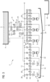
- FIG 2 shows another cooling system 2 for cooling hot-rolled rolling stock.
- bypass line 48 is connected directly to the coolant storage 4 on the output side. Consequently, in the present exemplary embodiment, the coolant flow discharged from the second main line 14 via the bypass line 48 is led from the bypass line 48 directly into the coolant storage 4 (instead of into the scale settling tank 44). Any processing of the coolant introduced into the coolant storage 4 via the bypass line 48 can be omitted here.
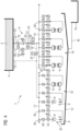
- FIG 3 shows another cooling system 2 for cooling hot-rolled rolling stock.
- bypass line 48 is connected on the input side directly to a connection element 53 of the second main line 14. Accordingly, in the present case, the coolant flow is discharged directly from the second main line 14 via the bypass line 48.
- bypass line 48 is connected directly to the coolant storage 4 on the output side. Consequently, in the present exemplary embodiment, the coolant flow discharged from the second main line 14 via the bypass line 48 is led from the bypass line 48 directly into the coolant storage 4 (instead of into the scale settling tank 44). Any processing of the coolant introduced into the coolant storage 4 via the bypass line 48 can be omitted here.
- FIG 4 shows another cooling system 2 for cooling hot-rolled rolling stock.
- bypass line 48 is connected on the input side directly to a connecting element 53 of the second main line 14. Accordingly, in the present case, the coolant flow is discharged directly from the second main line 14 via the bypass line 48.
- bypass line 48 is connected on the output side to a further connection element 55 of the second main line 14, the first-mentioned connection element 53 of the second main line 14 being arranged downstream of the coolant pump 20 and the further connection element 55 of the second main line 14 being arranged upstream of the coolant pump 20.
- the coolant flow discharged from the second main line 14 via the bypass line 48 is returned from the bypass line 48 directly into the second main line 14 (instead of being led into the scale settling tank 44).
- the shut-off device 50 of the bypass line 48 is open and the shut-off devices 40 of the coolant supply lines 36 of the second cooling section 34 are closed, the coolant flow circulates in the bypass line 48 and in the second main line 14 via the coolant pump 20.
- FIG 5 shows yet another cooling system 2 for cooling hot-rolled rolling stock.
- the cooling system 2 includes an additional bypass line 52 with a shut-off element 54, which is designed as a continuously adjustable valve.
- This bypass line 52 is directly connected to a connection element on the input side 53 of the second main line 14 connected. On the output side, this bypass line 52 is connected directly to the coolant storage 4.
- a further coolant flow is discharged from the second main line 14 via the additional bypass line 52, with the further coolant flow being guided from the additional bypass line 52 directly into the coolant storage 4.
- the shut-off device 50 of the first bypass line 50 is first opened.
- the shut-off device 54 of the additional bypass line 52 is then slowly opened and in return the shut-off device 50 of the first-mentioned bypass line 48 is closed again so that no further coolant is introduced into the scale settling tank 44, since the coolant introduced into the scale settling tank 44 is returned to the coolant storage 4 involves a higher energy expenditure than returning the coolant directly from the second main line 14 into the coolant storage 4.
- bypass line 48 as in FIG 1 be provided.
Landscapes
- Engineering & Computer Science (AREA)
- Chemical & Material Sciences (AREA)
- Mechanical Engineering (AREA)
- Materials Engineering (AREA)
- Thermal Sciences (AREA)
- Crystallography & Structural Chemistry (AREA)
- Physics & Mathematics (AREA)
- Metallurgy (AREA)
- Organic Chemistry (AREA)
- Heat Treatments In General, Especially Conveying And Cooling (AREA)
- Heat Treatment Of Strip Materials And Filament Materials (AREA)
- Metal Rolling (AREA)
- Fluid-Pressure Circuits (AREA)
Description
Die Erfindung betrifft eine Kühlanlage zum Kühlen von Walzgut, die mehrere Kühlbalken zum Aufbringen eines Kühlmittels auf das Walzgut, genau eine eigene Kühlmittelversorgungsleitung für jeden der Kühlbalken sowie ein Zuleitungssystem zum Leiten des Kühlmittels zu den Kühlmittelversorgungsleitungen umfasst, wobei jeder der Kühlbalken über seine eigene Kühlmittelversorgungsleitung mit dem Zuleitungssystem verbunden ist.The invention relates to a cooling system for cooling rolling stock, which comprises a plurality of cooling beams for applying a coolant to the rolling stock, exactly one coolant supply line for each of the cooling beams and a feed system for guiding the coolant to the coolant supply lines, each of the cooling beams having its own coolant supply line connected to the supply system.
Solch eine Kühlanlage wird genutzt, um eine definierte Abkühlung von Walzgut zu erreichen. Hierzu wird das Walzgut der Kühlanlage zugeführt. Mithilfe der Kühlbalken wird dann ein Kühlmittel, üblicherweise Wasser, auf das Walzgut aufgebracht.Such a cooling system is used to achieve a defined cooling of rolling stock. For this purpose, the rolling stock is fed to the cooling system. Using the cooling beams, a coolant, usually water, is then applied to the rolling stock.
Insbesondere beim sogenannten Warmwalzen ist eine definierte Abkühlung des Walzguts von zentraler Bedeutung, um gewünschte Materialeigenschaften des Walzguts, wie zum Beispiel eine gewünschte Gefügestruktur, zu erreichen.Particularly in so-called hot rolling, a defined cooling of the rolling stock is of central importance in order to achieve the desired material properties of the rolling stock, such as a desired microstructure.
Befindet sich während einer Walzpause kein Walzgut in der Kühlanlage, wird üblicherweise die Kühlmittelzufuhr zu den Kühlbalken unterbrochen. Zur Unterbrechung der Kühlmittelzufuhr werden typischerweise ein oder mehrere Absperrorgane der Kühlanlage eingesetzt.If there is no rolling stock in the cooling system during a rolling break, the coolant supply to the cooling beams is usually interrupted. One or more shut-off devices of the cooling system are typically used to interrupt the coolant supply.
Aus der
Eine Aufgabe der Erfindung ist es, eine verbesserte Kühlanlage zum Kühlen von Walzgut anzugeben.One object of the invention is to provide an improved cooling system for cooling rolled stock.
Diese Aufgabe wird erfindungsgemäß gelöst durch eine Kühlanlage mit den Merkmalen des Anspruchs 1.This object is achieved according to the invention by a cooling system with the features of claim 1.
Die erfindungsgemäße Kühlanlage umfasst mehrere Kühlbalken zum Aufbringen eines Kühlmittels auf das Walzgut. Außerdem umfasst die Kühlanlage genau eine eigene Kühlmittelversorgungsleitung für jeden der Kühlbalken. Das heißt, die Kühlanlage weist mehrere Kühlmittelversorgungsleitungen auf, wobei für jeden der Kühlbalken genau eine eigene Kühlmittelversorgungsleitung vorgesehen ist. Ferner umfasst die Kühlanlage ein Zuleitungssystem zum Leiten des Kühlmittels zu den Kühlmittelversorgungsleitungen.The cooling system according to the invention comprises several cooling beams for applying a coolant to the rolling stock. In addition, the cooling system includes exactly one coolant supply line for each of the cooling beams. This means that the cooling system has several coolant supply lines, with exactly one coolant supply line being provided for each of the cooling beams. Furthermore, the cooling system includes a supply system for guiding the coolant to the coolant supply lines.
Weiter ist bei der Kühlanlage vorgesehen, dass jeder der Kühlbalken über seine eigene Kühlmittelversorgungsleitung mit dem Zuleitungssystem verbunden ist. Mit anderen Worten, jeder der Kühlbalken ist über die genau eine Kühlmittelversorgungsleitung, die dem jeweiligen Kühlbalken zugeordnet ist bzw. für ihn vorgesehen ist, mit dem Zuleitungssystem verbunden.Furthermore, in the cooling system it is provided that each of the cooling beams is connected to the supply system via its own coolant supply line. In other words, each of the cooling beams is connected to the supply line system via exactly one coolant supply line that is assigned to the respective cooling beam or is intended for it.
Des Weiteren weist die Kühlanlage eine Bypassleitung zum Abführen eines Kühlmittelstroms aus dem Zuleitungssystem auf, welche eingangsseitig an ein Anschlusselement, insbesondere einen Anschlussstutzen, des Zuleitungssystems angeschlossen ist.Furthermore, the cooling system has a bypass line for discharging a coolant flow from the supply line system, which is connected on the input side to a connection element, in particular a connection piece, of the supply line system.
Ferner weist die Kühlanlage einen Kühlmittelspeicher, an welchen das Zuleitungssystem angeschlossen ist, eine Zunderrinne, ein mit der Zunderrinne verbundenes Zunderabsetzbecken sowie eine weitere Bypassleitung, die eingangsseitig an ein anderes Anschlusselement des Zuleitungssystems angeschlossen ist, auf, wobei eine der beiden Bypassleitungen ausgangsseitig an den Kühlmittelspeicher oder an ein weiteres Anschlusselement des Zuleitungssystems angeschlossen ist und die andere der beiden Bypassleitungen ausgangsseitig in die Zunderrinne oder in das Zunderabsetzbecken mündet.Furthermore, the cooling system has a coolant storage to which the supply line system is connected, a scale trough, a scale settling tank connected to the scale trough and a further bypass line, which is connected on the input side to another connection element of the supply line system, one of the two bypass lines being connected to the coolant storage on the output side or is connected to a further connection element of the supply line system and the other of the two bypass lines opens into the scale channel or into the scale settling basin on the output side.
Vorteilhafte Weiterbildungen der Erfindung sind Gegenstand abhängiger Patentansprüche sowie der nachfolgenden Beschreibung.Advantageous developments of the invention are the subject of dependent patent claims and the following description.
Die Erfindung geht von der Überlegung aus, dass bei einer raschen Unterbrechung der Kühlmittelzufuhr Druckstöße in der Kühlanlage, insbesondere in deren Leitungen, entstehen können, welche unter Umständen Komponenten der Kühlanlage beschädigen können und gegebenenfalls zu einem Ausfall der Kühlanlage führen können. Das Auftreten von Druckstößen, welche die Kühlanlage schädigen können, ist insbesondere dann problematisch, wenn die Kühlanlage im sogenannten Intensivkühlmodus betrieben wird, da in diesem Modus üblicherweise höhere Kühlmitteldrücke in den Leitungen der Kühlanlage herrschen als bei einem Betrieb der Kühlanlage im sogenannten Laminarkühlmodus.The invention is based on the idea that if the coolant supply is quickly interrupted, pressure surges can occur in the cooling system, in particular in its lines, which can, under certain circumstances, damage components of the cooling system and possibly lead to a failure of the cooling system. The occurrence of pressure surges, which can damage the cooling system, is particularly problematic when the cooling system is operated in the so-called intensive cooling mode, since in this mode there are usually higher coolant pressures in the lines of the cooling system than when the cooling system is operated in the so-called laminar cooling mode.
Die Erfindung ermöglicht bei einer Unterbrechung der Kühlmittelzufuhr zu den Kühlbalken ein Abfließen des Kühlmittels aus dem Zuleitungssystem über die Bypassleitung. Dem Kühlmittel wird also durch die Bypassleitung ein alternativer Strömungsweg bereitgestellt. Auf diese Weise können bei der Unterbrechung der Kühlmittelzufuhr zu den Kühlbalken Druckstöße in der Kühlanlage vermieden oder zumindest reduziert werden. Dadurch wiederum können Komponenten der Kühlanlage geschont werden und deren jeweilige Lebensdauer erhöht werden. Zweckmäßigerweise wird bei einer Unterbrechung der Kühlmittelzufuhr zu den Kühlbalken die Bypassleitung freigegeben.The invention allows the coolant to flow out of the supply system via the bypass line if the coolant supply to the cooling beams is interrupted. The bypass line therefore provides the coolant with an alternative flow path. In this way, pressure surges in the cooling system can be avoided or at least reduced when the coolant supply to the cooling beams is interrupted. This in turn means that components of the cooling system can be protected and their service life can be increased. The bypass line is expediently released if the coolant supply to the cooling beams is interrupted.
Dadurch, dass die Bypassleitung an ein Anschlusselement des Zuleitungssystems angeschlossen ist, können über die Bypassleitung mehrere Kühlbalken auf einmal, d.h. mehrere Kühlbalken mit derselben Bypassleitung, überbrückt werden. Eine eigene Bypassleitung für jede der Kühlmittelversorgungsleitungen - sowie gegebenenfalls ein eignes Absperrorgan für jede solche Bypassleitung - ist folglich nicht erforderlich. Dies ermöglicht eine konstruktiv einfache und kostengünstige Ausführung der Kühlanlage. Zudem wird dadurch ein steuerungstechnisch einfacher Betrieb der Kühlanlage ermöglicht.Because the bypass line is connected to a connection element of the supply line system, several cooling beams can be bridged at once via the bypass line, i.e. several cooling beams with the same bypass line. A separate bypass line for each of the coolant supply lines - and possibly a separate shut-off device for each such bypass line - is therefore not required. This enables a structurally simple and cost-effective design of the cooling system. In addition, this enables simple control technology operation of the cooling system.
Im Sinne der Erfindung kann als Leitung insbesondere ein Rohr, ein Rohrabschnitt oder ein System von miteinander verbunden Rohren aufgefasst werden.In the sense of the invention, the line can be used in particular a pipe, a pipe section or a system of interconnected pipes can be understood.
Der Begriff "verbunden" kann als Kurzform des Ausdrucks "fluidtechnisch verbunden" verstanden werden. Ein Element der Kühlanlage kann dann als mit einem anderen Element der Kühlanlage verbunden aufgefasst werden, wenn ein Fluid, insbesondere das zuvor erwähnte Kühlmittel, von einem der beiden Elemente zum anderen der beiden Elemente strömen kann.The term “connected” can be understood as a shortened form of the expression “fluid-technically connected”. An element of the cooling system can be considered to be connected to another element of the cooling system if a fluid, in particular the aforementioned coolant, can flow from one of the two elements to the other of the two elements.
Unter einem Aufbringen des Kühlmittels auf das Walzgut kann ein Applizieren des Kühlmittels auf eine Oberfläche des Walzguts verstanden werden. Das Kühlmittel kann von einer oder mehreren Seiten auf das Walzgut aufgebracht werden. Vorzugweise wird das Kühlmittel von oben und von unten auf das Walzgut aufgebracht.Applying the coolant to the rolling stock can be understood to mean applying the coolant to a surface of the rolling stock. The coolant can be applied to the rolling stock from one or more sides. The coolant is preferably applied to the rolling stock from above and below.
Die Bypassleitung ist vorzugsweise unmittelbar an das Anschlusselement des Zuleitungssystems angeschlossen. Das heißt, die Bypassleitung kann unmittelbar mit dem Zuleitungssystem verbunden sein.The bypass line is preferably connected directly to the connection element of the supply line system. This means that the bypass line can be connected directly to the supply system.
Zweckmäßigerweise ist die jeweilige Kühlmittelversorgungsleitung (ausgangsseitig) unmittelbar mit dem ihr zugeordneten Kühlbalken verbunden. Als Kühlmittelversorgungsleitung kann vorliegend eine Leitung aufgefasst werden, die genau einen der Kühlbalken mit dem Kühlmittel versorgt. Weiter ist es bevorzugt, wenn der jeweilige Kühlbalken ausschließlich über seine eigene Kühlmittelversorgungsleitung mit dem Zuleitungssystem verbunden ist. In bevorzugter Weise ist die jeweilige Kühlmittelversorgungsleitung (eingangsseitig) unmittelbar mit dem Zuleitungssystem verbunden.The respective coolant supply line (on the output side) is expediently connected directly to the cooling beam assigned to it. In the present case, a coolant supply line can be understood as a line that supplies exactly one of the cooling beams with the coolant. It is further preferred if the respective cooling beam is connected to the supply system exclusively via its own coolant supply line. Preferably, the respective coolant supply line (on the input side) is directly connected to the supply line system.
Über das Zuleitungssystem werden vorzugsweise alle der zuvor erwähnten Kühlbalken mit dem Kühlmittel versorgt. Das Zuleitungssystem kann eine oder mehrere Leitungen umfassen. Vorzugsweise umfasst das Zuleitungssystem mindestens eine Hauptleitung und mindestens eine Verteilerleitung. Zweckmäßigerweise ist die Hauptleitung ausgangsseitig mittelbar oder unmittelbar an die Verteilerleitung angeschlossen.All of the previously mentioned cooling beams are preferably supplied with the coolant via the supply system. The supply system can include one or more lines. Preferably, the supply system comprises at least one main line and at least one distribution line. The main line is expediently connected directly or indirectly to the distribution line on the output side.
Ferner ist es zweckmäßig, wenn die Kühlmittelversorgungsleitungen eingangsseitig mittelbar oder unmittelbar an die Verteilerleitung angeschlossen sind. Ausgangsseitig ist die jeweilige Kühlmittelversorgungsleitung vorteilhafterweise unmittelbar an den ihr zugeordneten Kühlbalken angeschlossen.Furthermore, it is expedient if the coolant supply lines are connected directly or indirectly to the distribution line on the input side. On the output side, the respective coolant supply line is advantageously connected directly to the cooling beam assigned to it.
Vorteilhafterweise umfasst die Kühlanlage eine Kühlmittelpumpe zum Erhöhen eines Kühlmitteldrucks im Zuleitungssystem. Es ist zweckmäßig, wenn die Kühlmittelpumpe in der zuvor erwähnten Hauptleitung angeordnet ist. Die Formulierung, dass die Kühlmittelpumpe zweckmäßigerweise in der Hauptleitung angeordnet ist, ist nicht notwendigerweise dahingehend zu verstehen, dass die Kühlmittelpumpe bei einer solchen Anordnung von der Hauptleitung umschlossen ist. Beispielweise kann die Hauptleitung einen ersten Leitungsabschnitt aufweisen, der an einen Eingang der Kühlmittelpumpe angeschlossen ist. Zudem kann die Hauptleitung einen zweiten Leitungsabschnitt aufweisen, der an einen Ausgang der Kühlmittelpumpe angeschlossen ist.The cooling system advantageously comprises a coolant pump for increasing a coolant pressure in the supply system. It is expedient if the coolant pump is arranged in the aforementioned main line. The wording that the coolant pump is expediently arranged in the main line is not necessarily to be understood as meaning that the coolant pump is enclosed by the main line in such an arrangement. For example, the main line can have a first line section that is connected to an inlet of the coolant pump. In addition, the main line can have a second line section that is connected to an output of the coolant pump.
Die Kühlmittelpumpe kann dazu eingesetzt werden, die Kühlleistung der Kühlanlage zu steuern. Zusätzlich zu der Kühlmittelpumpe können bei der Steuerung der Kühlleistung andere Elementen der Kühlanlage, wie zum Beispiel ein oder mehrere Regelventile, zum Einsatz kommen.The coolant pump can be used to control the cooling capacity of the cooling system. In addition to the coolant pump, other elements of the cooling system, such as one or more control valves, can be used to control the cooling capacity.
Dadurch, dass die Bypassleitung es ermöglicht, durch das Bereitstellen eines alternativen Strömungswegs bei einer Unterbrechung der Kühlmittelzufuhr zu den Kühlbalken das Kühlmittel in der Kühlanlage in Bewegung zu halten, ist es nicht erforderlich, bei der Unterbrechung der Kühlmittelzufuhr die Kühlmittelpumpe abzuschalten. Vielmehr kann auch dann, wenn die Kühlmittelzufuhr zu den Kühlbalken unterbrochen ist, ein vorgegebener Mindestvolumenstrom an Kühlmittel, welcher durch die Kühlmittelpumpe gefördert wird, sichergestellt werden.Because the bypass line makes it possible to keep the coolant moving in the cooling system by providing an alternative flow path when the coolant supply to the cooling beams is interrupted, it is not necessary to switch off the coolant pump when the coolant supply is interrupted. Rather, even if the coolant supply to the cooling beams is interrupted, a predetermined minimum volume flow of coolant, which is conveyed by the coolant pump, can be ensured.
In bevorzugter Weise ist die Kühlmittelpumpe mit einem frequenzgeregelten Antrieb ausgestattet. Mit einer solchen Pumpe kann der durch die Pumpe geförderte Kühlmittelvolumenstrom präzise eingestellt werden. Unter einer Kühlmittelpumpe mit frequenzgeregeltem Antrieb kann eine Pumpe verstanden werden, bei der ihre Drehzahl als Regelgröße dient.The coolant pump is preferably equipped with a frequency-controlled drive. With such a pump, the coolant volume flow delivered by the pump can be precisely adjusted. A coolant pump with a frequency-controlled drive can be understood as a pump in which its speed serves as a controlled variable.
Weiterhin kann die Kühlanlage mehrere Kühlmittelpumpen, insbesondere mehrere Kühlmittelpumpen der zuvor beschrieben Art, aufweisen.Furthermore, the cooling system can have several coolant pumps, in particular several coolant pumps of the type described above.
Eine bevorzugte Weiterbildung der Erfindung sieht vor, dass die Kühlanlage einen Hochtank zum Speichern des Kühlmittels aufweist.A preferred development of the invention provides that the cooling system has a high tank for storing the coolant.
Vorzugsweise ist das Zuleitungssystem, insbesondere dessen Hauptleitung, eingangsseitig unmittelbar an den Kühlmittelspeicher bzw. an ein Anschlusselement des Kühlmittelspeichers angeschlossen. Über das Zuleitungssystem kann das Kühlmittel aus dem Kühlmittelspeicher abgeleitet werden.The feed system, in particular its main line, is preferably connected on the input side directly to the coolant storage or to a connection element of the coolant storage. The coolant can be drained from the coolant storage via the supply system.
Des Weiteren kann das Anschlusselement des Zuleitungssystems ein Element der Hauptleitung oder der Verteilerleitung sein. Das heißt, die Bypassleitung kann eingangsseitig insbesondere an die Hauptleitung oder die Verteilerleitung des Zuleitungssystems angeschlossen sein. In dem Fall, dass die Bypassleitung an die Hauptleitung angeschlossen ist, ist die Bypassleitung eingangsseitig zweckmäßigerweise stromabwärts der zuvor erwähnten Kühlmittelpumpe an die Hauptleitung angeschlossen.Furthermore, the connection element of the feed system can be an element of the main line or the distribution line. This means that the bypass line can be connected on the input side, in particular to the main line or the distribution line of the supply system. In the case that the bypass line is connected to the main line, the bypass line is expediently connected to the main line on the input side downstream of the aforementioned coolant pump.
In einer vorteilhaften Ausgestaltung der Erfindung ist die Bypassleitung ausgangseitig an den Kühlmittelspeicher angeschlossen, insbesondere unmittelbar an den Kühlmittelspeicher angeschlossen. Dadurch kann der Kühlmittelstrom in den Kühlmittelspeicher (zurück-)geführt werden. Hierdurch wiederum kann erreicht werden, dass weniger Kühlmittel auf anderem Wege in den Kühlmittelspeicher eingebracht werden muss, um diesen wieder aufzufüllen, wodurch Energie eingespart werden kann.In an advantageous embodiment of the invention, the bypass line is connected to the coolant storage on the output side, in particular connected directly to the coolant storage. This allows the coolant flow to be (returned) to the coolant storage. This in turn means that less coolant has to be introduced into the coolant reservoir in other ways in order to refill it, which means energy can be saved.
Bei einer anderen vorteilhaften Ausgestaltung der Erfindung ist vorgesehen, dass die Bypassleitung ausgangseitig an ein weiteres Anschlusselement des Zuleitungssystems angeschlossen ist, insbesondere unmittelbar an das weitere Anschlusselement angeschlossen ist. Dadurch kann der Kühlmittelstrom in das Zuleitungssystem (zurück-)geführt werden. Hierdurch lässt sich ebenfalls erreichen, dass weniger Kühlmittel auf anderem Wege in den Kühlmittelspeicher eingebracht werden muss, um diesen wieder aufzufüllen, wodurch Energie eingespart werden kann.In another advantageous embodiment of the invention it is provided that the bypass line is connected on the output side to a further connection element of the supply line system, in particular is connected directly to the further connection element. This allows the coolant flow to be (returned) into the supply system. This also means that less coolant has to be introduced into the coolant storage by other means in order to refill it, which means energy can be saved.
Zweckmäßigerweise ist die Kühlanlage mit einem zusätzlichen Anschlusselement ausgestattet, welches stromaufwärts der zuvor erwähnten Kühlmittelpumpe angeordnet ist. Eine bevorzugte Ausführung der Erfindung sieht vor, dass die Bypassleitung ausgangsseitig an das zusätzliche Anschlusselement angeschlossen ist, insbesondere unmittelbar angeschlossen ist. Dieses zusätzliche Anschlusselement kann z.B. das weiter oben erwähnte weitere Anschlusselement des Zuleitungssystems oder ein Anschlusselement des Kühlmittelspeichers sein.The cooling system is expediently equipped with an additional connection element, which is arranged upstream of the aforementioned coolant pump. A preferred embodiment of the invention provides that the bypass line is connected on the output side to the additional connection element, in particular is connected directly. This additional connection element can be, for example, the further connection element of the supply line system mentioned above or a connection element of the coolant storage.
Zweckmäßigerweise kann ein in die Zunderrinne eingeleitetes Fluid, insbesondere das Kühlmittel, aus der Zunderrinne in das Zunderabsetzbecken abfließen.A fluid introduced into the scale trough, in particular the coolant, can expediently flow out of the scale trough into the scale settling tank.
In einer anderen vorteilhaften Erfindungsvariante ist vorgesehen, dass die Bypassleitung ausgangsseitig in die Zunderrinne oder in das Zunderabsetzbecken mündet. Hierbei muss die Bypassleitung nicht notwendigerweise mit der Zunderrinne oder dem Zunderabsetzbecken verbunden sein. Vielmehr kann die Formulierung, dass "die Bypassleitung ausgangsseitig in die Zunderrinne oder in das Zunderabsetzbecken mündet" dahingehend verstanden werden, dass der Ausgang der Bypassleitung derart angeordnet ist, dass der Kühlmittelstrom aus der Bypassleitung in die Zunderrinne oder in das Zunderabsetzbecken abfließen kann. Beispielsweise kann der Ausgang der Bypassleitung oberhalb der Zunderrinne oder des Zunderabsetzbeckens angeordnet sein.In another advantageous variant of the invention it is provided that the bypass line opens into the scale channel or into the scale settling basin on the output side. The bypass line does not necessarily have to be connected to the scale trough or the scale settling tank. Rather, the formulation that "the bypass line opens into the scale trough or into the scale settling tank on the output side" can be understood to mean that the outlet of the bypass line is arranged in such a way that the coolant flow can flow out of the bypass line into the scale trough or into the scale settling tank. For example, the outlet of the bypass line can be arranged above the scale trough or the scale settling tank.
Aus dem Zunderabsetzbecken kann das darin befindliche Kühlmittel, gegebenenfalls nachdem es eine Aufbereitungsanlage durchlaufen hat, in besagten Kühlmittelspeicher und/oder in das Zuleitungssystem (zurück-)geführt werden.The coolant contained therein can be (returned) from the scale settling tank, if necessary after it has passed through a processing plant, into said coolant storage and/or into the supply system.
Zweckmäßigerweise ist die weitere Bypassleitung eingangsseitig unmittelbar an das andere Anschlusselement angeschlossen.The further bypass line is expediently connected directly to the other connection element on the input side.
Es ist zweckmäßig, wenn die Kühlanlage ein Absperrorgan, insbesondere ein Ventil, aufweist, welches in der Bypassleitung angeordnet ist. Weiter ist es zweckmäßig, wenn die Kühlanlage mindestens ein weiteres Absperrorgan, insbesondere ein Ventil, zum Unterbrechen einer Kühlmittelzufuhr zu mindestens einem der Kühlbalken aufweist.It is expedient if the cooling system has a shut-off device, in particular a valve, which is arranged in the bypass line. Furthermore, it is expedient if the cooling system has at least one further shut-off device, in particular a valve, for interrupting a coolant supply to at least one of the cooling beams.
Das in der Bypassleitung angeordnete Absperrorgan und das weitere Absperrorgan weisen vorteilhafterweise zumindest im Wesentlichen gleiche Schaltzeiten auf. Auf diese Weise kann das Öffnen der Bypassleitung synchron mit dem Unterbrechen der Kühlmittelzufuhr zu den Kühlbalken durchgeführt werden. Umgekehrt kann dadurch das Schließen der Bypassleitung synchron mit dem (erneuten) Freigeben der Kühlmittelzufuhr zu den Kühlbalken durchgeführt werden.The shut-off device arranged in the bypass line and the further shut-off device advantageously have at least essentially the same switching times. In this way, the opening of the bypass line can be carried out synchronously with the interruption of the coolant supply to the cooling beams. Conversely, the closing of the bypass line can be carried out synchronously with the (re-)release of the coolant supply to the cooling beams.
Unter der Schaltzeit eines Absperrorgans kann diejenige Zeit verstanden werden, die das Absperrorgans (nach Erteilung eines Sperr- bzw. Entsperrbefehls) benötigt, um einen Leitungsquerschnitt derjenigen Leitung, in welcher das Absperrorgan angeordnet ist, aus einem vollständig geöffnetem Zustand heraus vollständig zu schließen bzw. um den Leitungsquerschnitt aus einem vollständig geschlossenen Zustand heraus vollständig zu öffnen.The switching time of a shut-off device can be understood as the time that the shut-off device needs (after issuing a blocking or unlocking command) to completely close or completely close a line cross-section of the line in which the shut-off device is arranged from a completely open state. to completely open the cable cross section from a completely closed state.
In bevorzugter Weise ist das weitere Absperrorgan im Zuleitungssystem, insbesondere in der zuvor erwähnten Hauptleitung des Zuleitungssystems, oder in einer der Kühlmittelversorgungsleitungen angeordnet.The further shut-off element is preferably arranged in the feed system, in particular in the aforementioned main line of the feed system, or in one of the coolant supply lines.
Weiterhin kann die Kühlanlage mehrere Absperrorgane aufweisen, die jeweils zum Unterbrechen einer Kühlmittelzufuhr zu mindestens einem der Kühlbalken eingerichtet sind. Für mehrere der Kühlbalken kann dabei ein gemeinsames Absperrorgan vorgesehen sein. Alternativ kann für jeden der Kühlbalken ein eigenes Absperrorgan vorgesehen sein. So kann beispielweise in jeder der Kühlmittelversorgungsleitungen ein Absperrorgan angeordnet sein.Furthermore, the cooling system can have several shut-off devices, each of which is set up to interrupt a coolant supply to at least one of the cooling beams. A common shut-off device can be provided for several of the cooling beams. Alternatively, a separate shut-off device can be provided for each of the cooling beams. For example, a shut-off device can be arranged in each of the coolant supply lines.
Zweckmäßigerweise ist in der weiteren Bypassleitung ein zusätzliches Absperrorgan, insbesondere ein Ventil, angeordnet. Das in der weiteren Bypassleitung angeordnete zusätzliche Absperrorgan kann identisch zu dem in der erstgenannten Bypassleitung angeordneten Absperrorgan ausgebildet sein. Insbesondere kann das zusätzliche Absperrorgan dieselbe Schaltzeit aufweisen wie das in der erstgenannten Bypassleitung angeordnete Absperrorgan.An additional shut-off device, in particular a valve, is expediently arranged in the further bypass line. The additional shut-off device arranged in the further bypass line can be designed identically to the shut-off device arranged in the first-mentioned bypass line. In particular, the additional shut-off device can have the same switching time as the shut-off device arranged in the first-mentioned bypass line.
Zweckmäßigerweise sind die Absperrorgane mithilfe einer Steuervorrichtung steuer- bzw. betätigbar. Das jeweilige Absperrorgan kann insbesondere elektrisch, pneumatisch und/oder hydraulisch betätigbar sein. Vorzugsweise lässt sich das jeweilige Absperrorgan nicht nur vollständig öffnen und vollständig schließen, sondern kann auch Zwischenstellungen, insbesondere kontinuierliche Zwischenstellungen, zwischen diesen beiden Zuständen annehmen. Mit anderen Worten, die Absperrorgane können kontinuierlich verstellbar sein.The shut-off devices can expediently be controlled or actuated using a control device. The respective shut-off device can in particular be actuated electrically, pneumatically and/or hydraulically. Preferably, the respective shut-off element can not only be completely opened and completely closed, but can also assume intermediate positions, in particular continuous intermediate positions, between these two states. In other words, the shut-off devices can be continuously adjustable.
Mindestens eine der Bypassleitungen kann mehrere Leitungsabschnitte umfassen, welche parallel zueinander geschaltet sind. Zweckmäßigerweise münden die parallel zueinander geschalteten Leitungsabschnitte eingangsseitig in einem gemeinsamen Leitungsabschnitt der jeweiligen Bypassleitung. Außerdem ist es zweckmäßig, wenn die parallel zueinander geschalteten Leitungsabschnitte ausgangsseitig in einen gemeinsamen Leitungsabschnitt der jeweiligen Bypassleitung münden. In den einzelnen parallel zueinander geschalteten Leitungsabschnitten kann jeweils ein Absperrorgan, insbesondere ein Ventil, angeordnet sein. Ein Vorteil einer solchen Ausgestaltung ist, dass die Absperrorgane - verglichen mit dem Fall, dass die jeweilige Bypassleitung ein einziges Absperrorgan aufweist - relativ klein und mit kurzen Schaltzeiten ausgeführt sein können.At least one of the bypass lines can comprise several line sections which are connected in parallel to one another. The line sections connected in parallel to one another expediently open on the input side into a common line section of the respective bypass line. In addition, it is expedient if the line sections connected in parallel to one another open on the output side into a common line section of the respective bypass line. A shut-off device, in particular a valve, can be arranged in each of the individual line sections connected in parallel to one another. An advantage Such an embodiment is that the shut-off devices - compared to the case where the respective bypass line has a single shut-off device - can be designed to be relatively small and with short switching times.
Ferner betrifft die Erfindung ein Verfahren zum Betreiben einer Kühlanlage.The invention further relates to a method for operating a cooling system.
Bei der im Zusammenhang mit dem Verfahren erwähnten Kühlanlage handelt es sich um die erfindungsgemäße Kühlanlage, insbesondere um eine ihrer oben beschriebenen vorteilhaften Weiterbildungen. Ferner können die im Zusammenhang mit dem Verfahren erwähnten gegenständlichen Elemente die bereits zuvor erwähnten Elemente sein.The cooling system mentioned in connection with the method is the cooling system according to the invention, in particular one of its advantageous developments described above. Furthermore, the material elements mentioned in connection with the method can be the elements already mentioned above.
Erfindungsgemäß ist bei dem Verfahren vorgesehen, dass über eine Bypassleitung, die eingangsseitig an ein Anschlusselement des Zuleitungssystems angeschlossen ist, ein Kühlmittelstrom aus dem Zuleitungssystem abgeführt wird.According to the invention, it is provided in the method that a coolant flow is discharged from the supply line system via a bypass line, which is connected on the input side to a connection element of the supply line system.
Der erstgenannte Kühlmittelstrom wird über die erstgenannte Bypassleitung in den Kühlmittelspeicher der Kühlanlage geführt oder in das Zuleitungssystem zurückgeführt, insbesondere unmittelbar in den Kühlmittelspeicher geführt oder unmittelbar in das Zuleitungssystem zurückgeführt. Dagegen wird der weitere Kühlmittelstrom vorteilhafterweise über die weitere Bypassleitung in die Zunderrinne oder in das Zunderabsetzbecken der Kühlanlage geführt, insbesondere unmittelbar in die Zunderrinne oder unmittelbar in das Zunderabsetzbecken der Kühlanlage geführt.The first-mentioned coolant flow is guided via the first-mentioned bypass line into the coolant storage of the cooling system or returned into the supply system, in particular led directly into the coolant storage or returned directly into the supply system. In contrast, the further coolant flow is advantageously guided via the further bypass line into the scale trough or into the scale settling basin of the cooling system, in particular directly into the scale trough or directly into the scale settling basin of the cooling system.
Zweckmäßigerweise wird der Kühlmittelstrom bei Abwesenheit eines zu kühlendes Walzguts in der Kühlanlage über die Bypassleitung aus dem Zuleitungssystem abgeführt.If there is no rolling stock to be cooled in the cooling system, the coolant flow is expediently discharged from the supply system via the bypass line.
Der Kühlmittelstrom, der über die Bypassleitung aus dem Zuleitungssystem abgeführt wird, kann ein Teilstrom eines das Zuleitungssystem durchfließenden Gesamt-Kühlmittelstroms oder eben besagter Gesamt-Kühlmittelstrom sein.The coolant flow, which is discharged from the supply line system via the bypass line, can be a partial flow of a total coolant flow flowing through the supply system or of said total coolant flow.
In bevorzugter Weise wird der Kühlmittelstrom über die Bypassleitung derart aus dem Zuleitungssystem abgeführt, dass der Kühlmittelstrom die Kühlmittelversorgungsleitungen umgeht. Mit anderen Worten, vorzugsweise wird der Kühlmittelstrom über die Bypassleitung derart geführt, dass der Kühlmittelstrom, anstatt in die Versorgungsleitungen zu strömen, woanders hin strömt, beispielweise in ein anderes Element der Kühlanlage oder aus der Kühlanlage heraus.Preferably, the coolant flow is discharged from the supply system via the bypass line in such a way that the coolant flow bypasses the coolant supply lines. In other words, the coolant flow is preferably guided via the bypass line in such a way that the coolant flow, instead of flowing into the supply lines, flows somewhere else, for example into another element of the cooling system or out of the cooling system.
Der Kühlmittelstrom kann aus der Bypassleitung beispielsweise in einen Kühlmitteleingang der Kühlanlage geführt werden, welcher stromaufwärts einer im Zuleitungssystem angeordneten Kühlmittelpumpe positioniert ist.The coolant flow can be guided from the bypass line, for example, into a coolant inlet of the cooling system, which is positioned upstream of a coolant pump arranged in the supply line system.
In einer vorteilhaften Ausführung der Erfindung wird der Kühlmittelstrom aus der Bypassleitung unmittelbar in den Kühlmittelspeicher geführt. Da hierbei normalerweise keine Verschmutzung des Kühlmittels erfolgt, kann auf eine Aufbereitung des Kühlmittels verzichtet werden, sodass ein Energiebedarf für eine Aufbereitung des in den Kühlmittelspeicher geführten Kühlmittels entfällt.In an advantageous embodiment of the invention, the coolant flow is led from the bypass line directly into the coolant storage. Since there is normally no contamination of the coolant, there is no need to process the coolant, so that there is no energy requirement for processing the coolant fed into the coolant storage.
In einer anderen vorteilhaften Ausführung der Erfindung wird der Kühlmittelstrom aus der Bypassleitung unmittelbar in das Zuleitungssystem zurückgeführt. Zweckmäßigerweise wird der Kühlmittelstrom hierbei stromaufwärts einer im Zuleitungssystem angeordneten Kühlmittelpumpe in das Zuleitungssystem wiedereingeführt. Mit anderen Worten, der Kühlmittelstrom kann insbesondere aus der Bypassleitung vor einen Eingang der Kühlmittelpumpe in das Zuleitungssystem zurückgeführt werden.In another advantageous embodiment of the invention, the coolant flow from the bypass line is returned directly to the supply line system. The coolant flow is expediently reintroduced into the supply system upstream of a coolant pump arranged in the supply system. In other words, the coolant flow can in particular be returned from the bypass line into the supply line system in front of an inlet of the coolant pump.
Eine vorteilhafte Erfindungsvariante sieht vor, dass der weitere Kühlmittelstrom aus der weiteren Bypassleitung unmittelbar in die Zunderrinne oder in das Zunderabsetzbecken geführt wird. In dem Fall, dass das Kühlmittel in die Zunderrinne geführt wird, wird das in der Zunderrinne befindliche Kühlmittel vorzugsweise aus der Zunderrinne in das Zunderabsetzbecken weitergeleitet.An advantageous variant of the invention provides that the further coolant flow from the further bypass line is led directly into the scale channel or into the scale settling tank. In the event that the coolant is fed into the scale trough, the coolant located in the scale trough is preferably forwarded from the scale trough into the scale settling tank.
Aus dem Zunderabsetzbecken kann ferner das darin befindliche Kühlmittel in den Kühlmittelspeicher und/oder in das Zuleitungssystem (zurück-)geführt werden. Bevor das im Zunderabsetzbecken befindliche Kühlmittel in den Kühlmittelspeicher und/oder in das Zuleitungssystem (zurück-)geführt wird, kann es gegebenenfalls in einer Aufbereitungsanlage aufbereitet, insbesondere von Fremdkörpern gereinigt, werden.The coolant contained therein can also be (returned) from the scale settling tank into the coolant storage and/or into the supply system. Before the coolant located in the scale settling tank is (returned) to the coolant storage and/or into the supply system, it can optionally be processed in a processing plant, in particular cleaned of foreign bodies.
Weiter wird der Kühlmittelstrom vorzugsweise stromabwärts der Kühlmittelpumpe, insbesondere zwischen der Kühlmittelpumpe und den Kühlmittelversorgungsleitungen, über die Bypassleitung aus dem Zuleitungssystem, abgeführt.Furthermore, the coolant flow is preferably discharged downstream of the coolant pump, in particular between the coolant pump and the coolant supply lines, via the bypass line from the supply system.
Die bisher gegebene Beschreibung vorteilhafter Ausgestaltungen der Erfindung enthält zahlreiche Merkmale, die in den einzelnen abhängigen Patentansprüchen teilweise zu mehreren zusammengefasst wiedergegeben sind. Diese Merkmale können jedoch zweckmäßigerweise auch einzeln betrachtet und zu sinnvollen weiteren Kombinationen zusammengefasst werden. Insbesondere sind diese Merkmale jeweils einzeln und in beliebiger geeigneter Kombination mit der erfindungsgemäßen Kühlanlage und dem erfindungsgemäßen Verfahren kombinierbar. So sind Verfahrensmerkmale auch als Eigenschaft der entsprechenden Vorrichtungseinheit zu sehen und umgekehrt.The description given so far of advantageous embodiments of the invention contains numerous features, some of which are summarized into several in the individual dependent patent claims. However, these features can also be conveniently considered individually and combined into further sensible combinations. In particular, these features can be combined individually and in any suitable combination with the cooling system according to the invention and the method according to the invention. Process features can also be seen as properties of the corresponding device unit and vice versa.
Auch wenn in der Beschreibung bzw. in den Patentansprüchen einige Begriffe jeweils im Singular oder in Verbindung mit einem Zahlwort verwendet werden, soll der Umfang der Erfindung für diese Begriffe nicht auf den Singular oder das jeweilige Zahlwort eingeschränkt sein.Even if some terms in the description or in the patent claims are used in the singular or in conjunction with a number word, the scope of the invention for these terms should not be limited to the singular or the respective number word.
Die oben beschriebenen Eigenschaften, Merkmale und Vorteile der Erfindung sowie die Art und Weise, wie diese erreicht werden, werden klarer und deutlicher verständlich im Zusammenhang mit der folgenden Beschreibung von erfindungsgemäßen und nicht-erfindungsgemäßen Ausführungsbeispielen der Erfindung, die im Zusammenhang mit den Zeichnungen näher erläutert werden und wobei
Es zeigen:
- FIG 1
- eine nicht-erfindungsgemäße Kühlanlage mit einer Bypassleitung, bei der die Bypassleitung eingangsseitig an eine Verteilerleitung angeschlossen ist und ausgangsseitig in ein Zunderabsetzbecken mündet;
- FIG 2
- eine andere, nicht-erfindungsgemäße Kühlanlage mit einer Bypassleitung, bei der die Bypassleitung eingangsseitig an eine Verteilerleitung angeschlossen ist und ausgangsseitig an einen Kühlmittelspeicher angeschlossen ist;
- FIG 3
- eine weitere, nicht-erfindungsgemäße Kühlanlage mit einer Bypassleitung, bei der die Bypassleitung eingangsseitig an eine Hauptleitung angeschlossen ist und ausgangsseitig an einen Kühlmittelspeicher angeschlossen ist;
- FIG 4
- noch eine andere, nicht-erfindungsgemäße Kühlanlage mit einer Bypassleitung, bei der die Bypassleitung sowohl eingangsseitig als auch ausgangsseitig an eine Hauptleitung angeschlossen ist; und
- FIG 5
- eine erfindungsgemäße Kühlanlage mit einer ersten und einer zweiten Bypassleitung, wobei die erste Bypassleitung eingangsseitig an eine Hauptleitung angeschlossen ist und ausgangsseitig an einen Kühlmittelspeicher angeschlossen ist und die zweite Bypassleitung eingangsseitig an eine Verteilerleitung angeschlossen ist und ausgangsseitig in ein Zunderabsetzbecken mündet.
- FIG 1
- a cooling system not according to the invention with a bypass line, in which the bypass line is connected on the input side to a distribution line and on the output side opens into a scale settling tank;
- FIG 2
- another cooling system not according to the invention with a bypass line, in which the bypass line is connected on the input side to a distribution line and on the output side is connected to a coolant storage;
- FIG 3
- a further cooling system not according to the invention with a bypass line, in which the bypass line is connected on the input side to a main line and on the output side is connected to a coolant storage;
- FIG 4
- yet another cooling system not according to the invention with a bypass line, in which the bypass line is connected to a main line on both the input and output sides; and
- FIG 5
- a cooling system according to the invention with a first and a second bypass line, wherein the first bypass line is connected on the input side to a main line and on the output side is connected to a coolant storage and the second bypass line is connected on the input side to a distribution line and opens on the output side into a scale settling tank.
Das Zuleitungssystem 9 umfasst eine erste Hauptleitung 10 sowie eine erste Verteilerleitung 12. Die erste Hauptleitung 10 ist eingangsseitig unmittelbar an den Kühlmittelspeicher 4 angeschlossen. Ausgangsseitig ist die erste Hauptleitung 10 unmittelbar an die erste Verteilerleitung 12 angeschlossen.The
Des Weiteren umfasst das Zuleitungssystem 9 eine zweite Hauptleitung 14 sowie eine zweite Verteilerleitung 16. Die zweite Hauptleitung 14 ist eingangsseitig unmittelbar an den Kühlmittelspeicher 4 angeschlossen. Ausgangsseitig ist die zweite Hauptleitung 14 unmittelbar an die zweite Verteilerleitung 16 angeschlossen. Ferner sind die erste und die zweite Hauptleitung 10, 14 über eine Verbindungsleitung 18 miteinander verbunden.Furthermore, the
Zudem umfasst die Kühlanlage 2 eine Kühlmittelpumpe 20, welche in der zweiten Hauptleitung 14 angeordnet ist und einen frequenzgeregelten Antrieb aufweist. Die Kühlmittelpumpe 20 ist zwischen einer ersten Wartungsklappe 22 und einer zweiten Wartungsklappe 24 angeordnet, welche in der zweiten Hauptleitung 14 angeordnet sind. Besagte Wartungsklappen 22, 24 dienen dazu, die Kühlmittelpumpe 20 zu Wartungs- und/oder Reparaturzwecken zu isolieren und dadurch warten, reparieren oder austauschen zu können, ohne das Kühlmittel 6 auslassen zu müssen.In addition, the
In der Verbindungsleitung 18, welche die erste Hauptleitung 10 mit der zweiten Hauptleitung 14 verbindet, ist ein als Ventil ausgebildetes Absperrorgan 26 zum Öffnen und Schließen der Verbindungsleitung 18 angeordnet. Außerdem ist in der zweiten Hauptleitung 14 zwischen der Kühlmittelpumpe 20 und der zweiten Verteilerleitung 16 ein als Ventil ausgebildetes Absperrorgan 28 zum Öffnen und Schließen der zweiten Hauptleitung 14 angeordnet.In the connecting
Die Kühlbalken 8 der Kühlanlage 2 sind entlang einer Kühlstrecke 30 angeordnet, durch die das Walzgut zu dessen Kühlung geführt wird, wobei die Kühlstrecke 30 im vorliegenden Ausführungsbeispiel in einen ersten Kühlstreckenabschnitt 32 und einen zweiten Kühlstreckenabschnitt 34 unterteilt ist.The cooling beams 8 of the
Die Begriffe "erster" und "zweiter" in Verbindung mit dem Begriff "Kühlstreckenabschnitt" dienen lediglich zur Unterscheidung der beiden Kühlstreckenabschnitte 32, 34 der Kühlstrecke 30. Die beiden Kühlstreckenabschnitte 32, 34 können so angeordnet sein, dass das zu kühlende Walzgut (zumindest bei seinem ersten Durchlauf durch die Kühlstrecke 30) zuerst durch den ersten Kühlstreckenabschnitt 32 und dann durch den zweiten Kühlstreckenabschnitt 34 geführt wird. Alternativ können die beiden Kühlstreckenabschnitte 32, 34 so angeordnet sein, dass das Walzgut (zumindest bei seinem ersten Durchlauf durch die Kühlstrecke 30) beispielweise zuerst durch den zweiten Kühlstreckenabschnitt 34 und dann durch den ersten Kühlstreckenabschnitt 32 geführt wird. Grundsätzlich kann also die Kühlanlage 2 derart ausgebildet sein, dass der zweite Kühlstreckenabschnitt 34 in Laufrichtung des Walzguts vor oder hinter dem ersten Kühlstreckenabschnitt 32 angeordnet ist.The terms “first” and “second” in conjunction with the term “cooling section” only serve to distinguish the two
Des Weiteren umfasst die Kühlanlage 2 mehrere Kühlmittelversorgungsleitungen 36 zum Versorgen der Kühlbalken 8 mit dem Kühlmittel, wobei für jeden den Kühlbalken 8 genau eine eigene Kühlmittelversorgungsleitung 36 vorgesehen ist.Furthermore, the
Jeder der Kühlbalken 8 des ersten Kühlstreckenabschnitts 32 ist über seine eigene Kühlmittelversorgungsleitung 36 mit der ersten Verteilerleitung 12 des Zuleitungssystems 9 verbunden. In analoger Weise ist jeder der Kühlbalken 8 des zweiten Kühlstreckenabschnitts 34 über seine eigene Kühlmittelversorgungsleitung 36 mit der zweiten Verteilerleitung 16 des Zuleitungssystems 9 verbunden. Die Kühlbalken 8 des ersten Kühlstreckenabschnitts 32 werden somit über die erste Verteilerleitung 12 mit dem Kühlmittel 6 versorgt, wohingegen die Kühlbalken 8 des zweiten Kühlstreckenabschnitts 34 über die zweite Verteilerleitung 16 mit dem Kühlmittel 6 versorgt werden.Each of the
In jedem der beiden Kühlstreckenabschnitte 32, 34 ist eine Hälfte der Kühlbalken 8 dazu eingerichtet, das Kühlmittel 6 von oben auf das zu kühlende Walzgut aufbringen, während die andere Hälfte der Kühlbalken 8 dazu eingerichtet ist, das Kühlmittel 6 von unten auf das zu kühlende Walzgut aufzubringen.In each of the two
Im vorliegenden Ausführungsbeispiel sind sämtliche Kühlbalken 8 des zweiten Kühlstreckenabschnitts 34 Kühlbalken gleicher Bauart. Diese Kühlbalken 8 weisen Düsen auf, aus welchen das Kühlmittel 6 im Kühlbetrieb der Kühlanlage 2 austritt. Dagegen unterscheiden sich die Kühlbalken 8 des ersten Kühlstreckenabschnitts 32 hinsichtlich ihrer Bauart voneinander. So weisen zum Beispiel einige der Kühlbalken 8 des ersten Kühlstreckenabschnitts 32 schwanenhalsähnlich geformte Kühlmittelauslassrohre auf. Prinzipiell könnten auch im ersten Kühlstreckenabschnitt 32 sämtliche Kühlbalken 8 gleicher Bauart sein.In the present exemplary embodiment, all cooling
Ferner ist in jeder der Kühlmittelversorgungsleitungen 36 eine Wartungsklappe 38 angeordnet. Darüber hinaus ist in jeder der Kühlmittelversorgungsleitungen 36 ein Absperrorgan 40 angeordnet, welches als kontinuierlich verstellbares Ventil ausgebildet ist und zur Regelung eines Kühlmitteldurchflusses durch die jeweilige Kühlmittelversorgungsleitung 36 dient.Furthermore, a
Außerdem umfasst die Kühlanlage 2 eine unterhalb der Kühlstrecke 30 angeordnete Zunderrinne 42 zum Auffangen des aus den Kühlbalken 8 austretenden Kühlmittels 6 sowie zum Auffangen von Zunderpartikeln. Ferner umfasst die Kühlanlage 2 ein Zunderabsetzbecken 44 zur Zunderpartikelablagerung. Das Zunderabsetzbecken 44 ist über eine Abführungsleitung 46 mit der Zunderrinne 42 verbunden, über welche in die Zunderrinne 42 eingeleitetes Kühlmittel 6 mit den darin befindlichen Zunderpartikeln in das Zunderabsetzbecken 44 geleitet wird.In addition, the
Weiterhin weist die Kühlanlage 2 eine Bypassleitung 48 sowie ein darin angeordnetes Absperrorgan 50 auf, welches als kontinuierlich verstellbares Ventil ausgebildet ist.Furthermore, the
Die Bypassleitung 48 ist eingangsseitig unmittelbar an ein Anschlusselement 51 der Verteilerleitung 16 angeschlossen. Ausgangseitig mündet die Bypassleitung 48 in das Zunderabsetzbecken 44. Weiterhin weisen das in der Bypassleitung 48 angeordnete Absperrorgan 50 und die in den Kühlmittelversorgungsleitungen 36 angeordneten Absperrorgane 40 zumindest im Wesentlichen gleiche Schaltzeiten auf.The
Der zweite Kühlstreckenabschnitt 34 der Kühlanlage 2 kann wahlweise in einem Laminarkühlmodus, in einem Quasilaminarkühlmodus oder in einem Intensivkühlmodus betrieben werden.The second
Im Laminarkühlmodus wird das Kühlmittel 6 aus dem Kühlmittelspeicher 4 über die erste Hauptleitung 10 zu den Kühlmittelversorgungsleitungen 36 des ersten Kühlstreckenabschnitts 32 sowie zu den Kühlmittelversorgungsleitungen 36 des zweiten Kühlstreckenabschnitts 34 geleitet. Das in der Verbindungsleitung 18 angeordnete Absperrorgan 26 ist dabei geöffnet, wohingegen das in der zweiten Hauptleitung 14 angeordnete Absperrorgan 28 geschlossen ist. Die Kühlmittelpumpe 20 ist in diesem Kühlmodus ausgeschaltet.In the laminar cooling mode, the
Im Quasilaminarkühlmodus und im Intensivkühlmodus wird das Kühlmittel 6 aus dem Kühlmittelspeicher 4 über die erste Hauptleitung 10 zu den Kühlmittelversorgungsleitungen 36 des ersten Kühlstreckenabschnitts 32 und über die zweite Hauptleitung 14 zu den Kühlmittelversorgungsleitungen 36 des zweiten Kühlstreckenabschnitts 34 geleitet. Das in der Verbindungsleitung 18 angeordnete Absperrorgan 26 ist dabei geschlossen, wohingegen das in der zweiten Hauptleitung 14 angeordnete Absperrorgan 28 geöffnet ist.In the quasi-laminar cooling mode and in the intensive cooling mode, the
Mit anderen Worten, im Laminarkühlmodus werden alle Kühlmittelversorgungsleitungen 36 der Kühlstrecke 30 über die erste Hauptleitung 10 mit dem Kühlmittel 6 versorgt. Im Quasilaminarkühlmodus und im Intensivkühlmodus hingegen werden nur die Kühlmittelversorgungsleitungen 36 des ersten Kühlstreckenabschnitts 32 über die erste Hauptleitung 10 mit dem Kühlmittel 6 versorgt, während die Kühlmittelversorgungsleitungen 36 des zweiten Kühlstreckenabschnitts 34 über die zweite Hauptleitung 14 mit dem Kühlmittel 6 versorgt werden.In other words, in the laminar cooling mode, all
Im Quasilaminarkühlmodus wird die Kühlmittelpumpe 20 mit einer Drehzahl betrieben, bei der ein beim Durchströmen der Kühlmittelpumpe 20 entstehender Druckabfall im Kühlmittel 6 zumindest im Wesentlichen kompensiert wird. Dagegen wird im Intensivkühlmodus mithilfe der Kühlmittelpumpe 20 der Kühlmitteldruck in der zweiten Hauptleitung 14 über den durch den Kühlmittelspeicher 4 resultierenden Druck hinaus erhöht.In the quasi-laminar cooling mode, the
In jedem der drei Kühlmodi wird das Kühlmittel sowohl von Kühlbalken 8 des ersten Kühlstreckenabschnitts 32 als auch von Kühlbalken 8 des zweiten Kühlstreckenabschnitts 34 auf das Walzgut aufgebracht. Die Kühlbalken 8 des ersten Kühlstreckenabschnitts 32 werden dabei stets über die erste Hauptleitung 10 und nicht über die zweite Hauptleitung 14 mit dem Kühlmittel 6 versorgt.In each of the three cooling modes, the coolant is applied to the rolling stock both by cooling
Wird eine Walzpause eingelegt oder soll eine Kühlung des Walzguts über Luft (statt über das Kühlmittel) erfolgen, während die Kühlanlage 2 im Intensivkühlmodus betrieben wird, so wird die Kühlmittelzufuhr zu den Kühlbalken 8 mithilfe der in den Kühlmittelversorgungsleitungen 36 angeordneten Absperrorgane 40 unterbrochen. Zugleich gibt das in der Bypassleitung 48 angeordnete Absperrorgan 50 die Bypassleitung 48 frei.If a rolling break is taken or if the rolling stock is to be cooled via air (instead of via the coolant) while the
Die Kühlmittelpumpe 20 wird hierbei nicht ausgeschaltet, sondern in Betrieb gehalten, um ein späteres erneutes Anfahren der Kühlmittelpumpe 20 zu vermeiden. Gegebenenfalls wird ihre Drehzahl reduziert, um den Kühlmitteldurchfluss durch die zweite Hauptleitung 14 zu reduzieren.The
Über die Bypassleitung 48 wird ein Kühlmittelstrom aus der zweiten Hauptleitung 14 abgeführt, sodass der Kühlmittelstrom die Kühlmittelversorgungsleitungen 36 des zweiten Kühlstreckenabschnitts 34 umgeht. Das heißt, der Kühlmittelstrom strömt in die Bypassleitung 48 ein, statt in besagte Verteilerleitungen 36 einzuströmen. Durch das Abführen des Kühlmittelstroms über die Bypassleitung 48 werden bei der vorliegenden Kühlanlage 2 Druckstöße vermieden oder zumindest reduziert.A coolant flow is discharged from the second
Im vorliegenden Ausführungsbeispiel wird der Kühlmittelstrom von der Bypassleitung 48 nicht unmittelbar aus der zweiten Hauptleitung 14 abgeführt, sondern über die mit der zweiten Hauptleitung 14 verbundene zweite Verteilerleitung 16. Aus der Bypassleitung 48 wird der Kühlmittelstrom unmittelbar in das Zunderabsetzbecken 44 geführt.In the present exemplary embodiment, the coolant flow from the
Aus dem Zunderabsetzbecken 44 kann das darin befindliche Kühlmittel 6 zur Wiederverwendung entweder direkt oder über eine (figürlich nicht dargestellte) Kühlmittelaufbereitungsanlage in den Kühlmittelspeicher 4 gefördert werden.From the
Die Beschreibungen der nachfolgenden Ausführungsbeispiele beschränken sich jeweils primär auf die Unterschiede zu dem vorangegangenen, im Zusammenhang mit
Bei diesem Ausführungsbeispiel ist die Bypassleitung 48 ausgangsseitig unmittelbar an den Kühlmittelspeicher 4 angeschlossen. Folglich wird im vorliegenden Ausführungsbeispiel der aus der zweiten Hauptleitung 14 über die Bypassleitung 48 abgeführte Kühlmittelstrom aus der Bypassleitung 48 unmittelbar in den Kühlmittelspeicher 4 (anstatt in das Zunderabsetzbecken 44) geführt. Eine etwaige Aufbereitung des über die Bypassleitung 48 in den Kühlmittelspeicher 4 eingeführten Kühlmittels kann hierbei entfallen.In this exemplary embodiment, the
Bei diesem Ausführungsbeispiel ist die Bypassleitung 48 eingangsseitig unmittelbar an ein Anschlusselement 53 der zweiten Hauptleitung 14 angeschlossen. Entsprechend wird im vorliegenden Fall der Kühlmittelstrom über die Bypassleitung 48 unmittelbar aus der zweiten Hauptleitung 14 abgeführt.In this exemplary embodiment, the
Ferner ist die Bypassleitung 48 ausgangsseitig unmittelbar an den Kühlmittelspeicher 4 angeschlossen. Folglich wird im vorliegenden Ausführungsbeispiel der aus der zweiten Hauptleitung 14 über die Bypassleitung 48 abgeführte Kühlmittelstrom aus der Bypassleitung 48 unmittelbar in den Kühlmittelspeicher 4 (anstatt in das Zunderabsetzbecken 44) geführt. Eine etwaige Aufbereitung des über die Bypassleitung 48 in den Kühlmittelspeicher 4 eingeführten Kühlmittels kann hierbei entfallen.Furthermore, the
Des Weiteren kann auf ein Abschalten der Kühlmittelpumpe 20 bei einer Unterbrechung der Kühlmittelzufuhr zu den Kühlbalken 8 verzichtet werden.Furthermore, it is not necessary to switch off the
Bei dem Ausführungsbeispiel aus
Ferner ist die Bypassleitung 48 ausgangsseitig an ein weiteres Anschlusselement 55 der zweiten Hauptleitung 14 anschlossen, wobei das erstgenannte Anschlusselement 53 der zweiten Hauptleitung 14 stromabwärts der Kühlmittelpumpe 20 angeordnet ist und das weitere Anschlusselement 55 der zweiten Hauptleitung 14 stromaufwärts der Kühlmittelpumpe 20 angeordnet ist.Furthermore, the
Im vorliegenden Ausführungsbeispiel wird der aus der zweiten Hauptleitung 14 über die Bypassleitung 48 abgeführte Kühlmittelstrom aus der Bypassleitung 48 wieder unmittelbar in die zweite Hauptleitung 14 zurückgeführt (anstatt in das Zunderabsetzbecken 44 geführt zu werden). Solange das Absperrorgan 50 der Bypassleitung 48 geöffnet ist und die Absperrorgane 40 der Kühlmittelversorgungsleitungen 36 des zweiten Kühlstreckenabschnitts 34 geschlossen sind, zirkuliert der Kühlmittelstrom in der Bypassleitung 48 und in der zweiten Hauptleitung 14 über die Kühlmittelpumpe 20.In the present exemplary embodiment, the coolant flow discharged from the second
Bei diesem Ausführungsbeispiel umfasst die Kühlanlage 2 eine zusätzliche Bypassleitung 52 mit einem Absperrorgan 54, welches als kontinuierlich verstellbares Ventil ausgebildet ist. Diese Bypassleitung 52 ist eingangsseitig unmittelbar an ein Anschlusselement 53 der zweiten Hauptleitung 14 angeschlossen. Ausgangsseitig ist diese Bypassleitung 52 unmittelbar an den Kühlmittelspeicher 4 angeschlossen.In this exemplary embodiment, the
Über die zusätzliche Bypassleitung 52 wird ein weiterer Kühlmittelstrom aus der zweiten Hauptleitung 14 abgeführt, wobei der weitere Kühlmittelstrom aus der zusätzlichen Bypassleitung 52 unmittelbar in den Kühlmittelspeicher 4 geführt wird.A further coolant flow is discharged from the second
Um bei einer Unterbrechung der Kühlmittelzufuhr zu den Kühlbalken 8 einen Druckstoß effektiv zu vermeiden, wird zuerst das Absperrorgan 50 der ersten Bypassleitung 50 geöffnet. Danach wird das Absperrorgan 54 der zusätzlichen Bypassleitung 52 langsam geöffnet und im Gegenzug das Absperrorgan 50 der erstgenannten Bypassleitung 48 wieder geschlossen, damit kein weiteres Kühlmittel in das Zunderabsetzbecken 44 eingeleitet wird, da ein Zurückführen des in das Zunderabsetzbecken 44 eingeleiteten Kühlmittels in den Kühlmittelspeicher 4 mit einem höheren Energieaufwand einhergeht als ein direktes Zurückführen des Kühlmittels aus der zweiten Hauptleitung 14 in den Kühlmittelspeicher 4.In order to effectively avoid a pressure surge when the coolant supply to the cooling beams 8 is interrupted, the shut-off
Eine Kombination mehrerer Bypassleitungen ist auch bei den Ausführungsbeispielen aus
- 22
- KühlanlageCooling system
- 44
- KühlmittelspeicherCoolant storage
- 66
- Kühlmittelcoolant
- 88th
- KühlbalkenChilled beams
- 99
- Zuleitungssystemsupply system
- 1010
- Hauptleitungmain line
- 1212
- Verteilerleitungdistribution line
- 1414
- Hauptleitungmain line
- 1616
- Verteilerleitungdistribution line
- 1818
- Verbindungsleitungconnecting line
- 2020
- Kühlmittelpumpecoolant pump
- 2222
- WartungsklappeMaintenance hatch
- 2424
- WartungsklappeMaintenance hatch
- 2626
- AbsperrorganShut-off device
- 2828
- AbsperrorganShut-off device
- 3030
- Kühlstreckecooling section
- 3232
- KühlstreckenabschnittCooling section
- 3434
- KühlstreckenabschnittCooling section
- 3636
- Versorgungsleitungsupply line
- 3838
- WartungsklappeMaintenance hatch
- 4040
- AbsperrorganShut-off device
- 4242
- ZunderrinneTinder gutter
- 4444
- ZunderabsetzbeckenTinder settling tank
- 4646
- Abführungsleitungdischarge line
- 4848
- BypassleitungBypass line
- 5050
- AbsperrorganShut-off device
- 5151
- AnschlusselementConnection element
- 5252
- BypassleitungBypass line
- 5353
- AnschlusselementConnection element
- 5454
- AbsperrorganShut-off device
- 5555
- AnschlusselementConnection element
Claims (13)
- Cooling system (2) for cooling rolling stock, comprising- a plurality of cooling bars (8) for applying a coolant to the rolling stock,- exactly one dedicated coolant supply line (36) for each of the cooling bars (8),- a feed line system (9) for directing the coolant to the coolant supply lines (36), wherein each of the cooling bars (8) is connected to the feed line system (9) by way of its dedicated coolant supply line (36),- a bypass line (48, 52) for discharging a coolant flow from the feed line system (9), which is connected on the input side to a connection element (51, 53) of the feed line system (9),- a coolant reservoir (4), to which the feed line system (9) is connected,- a scale channel (42),- a scale settling tank (44) connected to the scale channel (42),- a coolant pump (20) for increasing a coolant pressure in the feed line system (9), and- a further bypass line (48, 52), which is connected on the input side to another connection element (51, 53) of the feed line system (9), wherein one of the two bypass lines (48, 52) is connected on the output side to the coolant reservoir (4) or to a further connection element (55) of the feed line system (9) that is arranged upstream of the coolant pump (20), and the other of the two bypass lines (48, 52) opens out on the output side into the scale channel (42) or into the scale settling tank (44) .
- Cooling system (2) according to Claim 1,
characterized in that the coolant reservoir (4) is an elevated tank. - Cooling system (2) according to Claim 1 or 2,
characterized in that the bypass line (48, 52) is connected on the output side to the coolant reservoir (4). - Cooling system (2) according to Claim 1 or 2,
characterized in that the bypass line (48, 52) is connected on the output side to the further connection element (55) of the feed line system (9). - Cooling system (2) according to one of the preceding claims, characterized in that the coolant pump (20) has a frequency-controlled drive.
- Cooling system (2) according to Claim 1 or 2,
characterized in that the bypass line (48, 52) opens out on the output side into the scale channel (42) or into the scale settling tank (44). - Cooling system (2) according to one of the preceding claims, characterized by a shut-off member (50, 54), which is arranged in the bypass line (48, 52), and at least one further shut-off member (40) for interrupting a coolant feed to at least one of the cooling bars (8).
- Cooling system (2) according to Claim 7,
characterized in that the shut-off member (50, 54) arranged in the bypass line (48, 52) and the further shut-off member (40) have at least substantially the same switching times. - Cooling system (2) according to Claim 7 or 8,
characterized in that the further shut-off member (40) is arranged in the feed line system (9) or in one of the coolant supply lines (36). - Method for operating a cooling system (2) according to one of the preceding claims,
characterized in that- by way of the bypass line (48, 52), which is connected on the input side to the connection element (51, 53) of the feed line system (9), a coolant flow is discharged from the feed line system (9),- the coolant flow is sent by way of the bypass line (48, 52) into the coolant reservoir (4) of the cooling system (2) or is sent back into the feed line system (9) upstream of the coolant pump (20), and- a further coolant flow is sent by way of the further bypass line (48, 52) into the scale channel (42) or into the scale settling tank (44) of the cooling system (2). - Method according to Claim 10,
characterized in that the coolant flow from the bypass line (48, 52) is sent directly into the coolant reservoir (4) of the cooling system (2). - Method according to Claim 10,
characterized in that the coolant flow from the bypass line (48, 52) is sent back directly into the feed line system (9), wherein the coolant flow is reintroduced into the feed line system (9) upstream of the coolant pump (20) arranged in the feed line system (9). - Method according to Claim 10,
characterized in that the further coolant flow from the further bypass line (48, 52) is sent directly into a scale channel (42) or into a scale settling tank (44) of the cooling system (2).
Applications Claiming Priority (2)
| Application Number | Priority Date | Filing Date | Title |
|---|---|---|---|
| EP16204004.2A EP3335812A1 (en) | 2016-12-14 | 2016-12-14 | Cooling system for cooling rolling stock |
| PCT/EP2017/080669 WO2018108518A2 (en) | 2016-12-14 | 2017-11-28 | Cooling system for cooling rolling stock |
Publications (3)
| Publication Number | Publication Date |
|---|---|
| EP3554727A2 EP3554727A2 (en) | 2019-10-23 |
| EP3554727B1 EP3554727B1 (en) | 2020-12-30 |
| EP3554727B2 true EP3554727B2 (en) | 2024-01-31 |
Family
ID=57569982
Family Applications (2)
| Application Number | Title | Priority Date | Filing Date |
|---|---|---|---|
| EP16204004.2A Withdrawn EP3335812A1 (en) | 2016-12-14 | 2016-12-14 | Cooling system for cooling rolling stock |
| EP17804569.6A Active EP3554727B2 (en) | 2016-12-14 | 2017-11-28 | Cooling system for cooling rolling stock |
Family Applications Before (1)
| Application Number | Title | Priority Date | Filing Date |
|---|---|---|---|
| EP16204004.2A Withdrawn EP3335812A1 (en) | 2016-12-14 | 2016-12-14 | Cooling system for cooling rolling stock |
Country Status (7)
| Country | Link |
|---|---|
| US (1) | US11103906B2 (en) |
| EP (2) | EP3335812A1 (en) |
| JP (1) | JP7210450B2 (en) |
| CN (1) | CN110049830A (en) |
| MX (1) | MX2019005854A (en) |
| RU (1) | RU2755133C2 (en) |
| WO (1) | WO2018108518A2 (en) |
Families Citing this family (4)
| Publication number | Priority date | Publication date | Assignee | Title |
|---|---|---|---|---|
| EP3335812A1 (en) * | 2016-12-14 | 2018-06-20 | Primetals Technologies Austria GmbH | Cooling system for cooling rolling stock |
| US20200188975A1 (en) | 2018-12-12 | 2020-06-18 | Primetals Technologies USA LLC | Temperature control system |
| DE102022210057A1 (en) * | 2022-09-23 | 2024-03-28 | Sms Group Gmbh | Method and computer program for operating a production plant for a metal product |
| DE102022128358A1 (en) * | 2022-10-26 | 2024-05-02 | Sms Group Gmbh | Cooling module, cooling group, cooling system, process, hot rolled metallic strip product and use |
Family Cites Families (15)
| Publication number | Priority date | Publication date | Assignee | Title |
|---|---|---|---|---|
| JPS5256052A (en) * | 1975-11-04 | 1977-05-09 | Hitachi Ltd | Roll coolant device |
| JPS5479817A (en) * | 1977-12-07 | 1979-06-26 | Mitsubishi Heavy Ind Ltd | Water supplying device used pure fluidic control element without movable part |
| SU1224031A1 (en) * | 1983-12-30 | 1986-04-15 | Всесоюзный Научно-Исследовательский И Проектный Институт По Очистке Технологических Газов,Сточных Вод И Использованию Вторичных Энергоресурсов Предприятий Черной Металлургии "Вниипичерметэнергоочистка" | Apparatus for water cooling of rolled stock and rolling-mill equipment |
| JPS6267605A (en) * | 1985-09-20 | 1987-03-27 | Hitachi Ltd | Sequential controller |
| JPS6267605U (en) * | 1985-10-14 | 1987-04-27 | ||
| SU1703213A1 (en) * | 1989-12-11 | 1992-01-07 | Научно-Производственное Объединение По Защите Атмосферы, Водоемов, Использованию Вторичных Энергоресурсов И Охлаждению Металлургических Агрегатов На Предприятиях Черной Металлургии "Энергосталь" | Apparatus for water cooling of rolled stock and rolling equipment |
| JP5210136B2 (en) * | 2008-12-05 | 2013-06-12 | 株式会社神戸製鋼所 | Cooling water supply control method for water cooling device of steel strip rolling equipment |
| CN202192104U (en) | 2011-07-06 | 2012-04-18 | 安徽精诚铜业股份有限公司 | Electronic control system for water supply of hot rolling mill |
| EP2644718A1 (en) * | 2012-03-27 | 2013-10-02 | Siemens Aktiengesellschaft | Pressure stabilisation method |
| CN103624093A (en) * | 2012-08-29 | 2014-03-12 | 江苏博际喷雾系统有限公司 | Cooling system for intermediate steel billets |
| DE102012215599A1 (en) | 2012-09-03 | 2014-03-06 | Sms Siemag Ag | Method and device for the dynamic supply of a cooling device for cooling metal strip or other rolling stock with coolant |
| JP6024407B2 (en) * | 2012-11-15 | 2016-11-16 | Jfeスチール株式会社 | Steel plate cooling device and cooling method |
| CN203750996U (en) * | 2014-01-14 | 2014-08-06 | 中冶南方工程技术有限公司 | Turbid circulating water supply system for rolling mill in hot-rolling rod and wire production line |
| EP2921239A1 (en) * | 2014-03-21 | 2015-09-23 | Siemens VAI Metals Technologies GmbH | Cooling of a hot rolled product |
| EP3335812A1 (en) * | 2016-12-14 | 2018-06-20 | Primetals Technologies Austria GmbH | Cooling system for cooling rolling stock |
-
2016
- 2016-12-14 EP EP16204004.2A patent/EP3335812A1/en not_active Withdrawn
-
2017
- 2017-11-28 US US16/463,432 patent/US11103906B2/en active Active
- 2017-11-28 WO PCT/EP2017/080669 patent/WO2018108518A2/en not_active Ceased
- 2017-11-28 RU RU2019120028A patent/RU2755133C2/en active
- 2017-11-28 CN CN201780077797.7A patent/CN110049830A/en active Pending
- 2017-11-28 JP JP2019531754A patent/JP7210450B2/en active Active
- 2017-11-28 MX MX2019005854A patent/MX2019005854A/en unknown
- 2017-11-28 EP EP17804569.6A patent/EP3554727B2/en active Active
Also Published As
| Publication number | Publication date |
|---|---|
| RU2019120028A (en) | 2021-01-15 |
| MX2019005854A (en) | 2019-08-12 |
| RU2755133C2 (en) | 2021-09-13 |
| WO2018108518A2 (en) | 2018-06-21 |
| US11103906B2 (en) | 2021-08-31 |
| JP2020513328A (en) | 2020-05-14 |
| US20200331046A1 (en) | 2020-10-22 |
| RU2019120028A3 (en) | 2021-05-27 |
| EP3335812A1 (en) | 2018-06-20 |
| EP3554727B1 (en) | 2020-12-30 |
| JP7210450B2 (en) | 2023-01-23 |
| EP3554727A2 (en) | 2019-10-23 |
| CN110049830A (en) | 2019-07-23 |
| WO2018108518A3 (en) | 2018-11-01 |
Similar Documents
| Publication | Publication Date | Title |
|---|---|---|
| EP3554727B2 (en) | Cooling system for cooling rolling stock | |
| WO2014032838A1 (en) | Method and device for dynamically supplying coolant to a cooling device for cooling metal strip or other rolled stock | |
| DE102018006965A1 (en) | Cutting fluid supply device for a machine tool | |
| EP3444038B1 (en) | Injection device and method for cooling a metallic strand in a continuous casting machine | |
| EP2841869B1 (en) | Method for providing a cooling medium in a secondary circuit | |
| EP1900449B1 (en) | Spray header of a hydraulic descaling facility and method for operating such a spray header | |
| DE112004000565B4 (en) | Switching a fluid flow by diverting | |
| DE102011003194A1 (en) | roller device | |
| EP2640552A1 (en) | Water abrasive suspension jet cutting system | |
| DE102004034270B4 (en) | Plant for discharging flowable fluids, in particular paints and varnishes and method for operating the system | |
| DE19805377A1 (en) | Spray beam for hydraulic de-scaling plant | |
| DE102013214810B4 (en) | Device and method for controlled secondary cooling of a cast metal strand | |
| DE102014100839B4 (en) | Water abrasive suspension cutting device, method for its control and computer program | |
| DE102013214809A1 (en) | Apparatus and method for controlled multi-material secondary cooling of a cast metal strand | |
| DE102006014572A1 (en) | Device and method for air distribution in a cargo plane | |
| EP1663572B1 (en) | Device and method for aerosol lubrication using a bypass valve | |
| DE10025639A1 (en) | Nozzle bar for cooling or descaling metal billets, especially rolled stock | |
| EP1427549B1 (en) | Spray beam for a hydraulic descaling facility | |
| DE2403765A1 (en) | Sieve for melted plastics gives continuous throughput - without surge during sieve replacement and permits flushing of sieve | |
| EP0924003B1 (en) | Cooling device for cooling a moving hot metal strip | |
| WO2024003169A1 (en) | Fuel cell system and operating method | |
| EP3993917B1 (en) | Cooling line with valves and pressure vessels for preventing pressure surges | |
| EP3765216A1 (en) | Cooling unit of a laminar cooling device | |
| DE202015105271U1 (en) | Device for lubricant supply | |
| DE4422108A1 (en) | Valve device |
Legal Events
| Date | Code | Title | Description |
|---|---|---|---|
| STAA | Information on the status of an ep patent application or granted ep patent |
Free format text: STATUS: UNKNOWN |
|
| STAA | Information on the status of an ep patent application or granted ep patent |
Free format text: STATUS: THE INTERNATIONAL PUBLICATION HAS BEEN MADE |
|
| PUAI | Public reference made under article 153(3) epc to a published international application that has entered the european phase |
Free format text: ORIGINAL CODE: 0009012 |
|
| STAA | Information on the status of an ep patent application or granted ep patent |
Free format text: STATUS: REQUEST FOR EXAMINATION WAS MADE |
|
| 17P | Request for examination filed |
Effective date: 20190715 |
|
| AK | Designated contracting states |
Kind code of ref document: A2 Designated state(s): AL AT BE BG CH CY CZ DE DK EE ES FI FR GB GR HR HU IE IS IT LI LT LU LV MC MK MT NL NO PL PT RO RS SE SI SK SM TR |
|
| AX | Request for extension of the european patent |
Extension state: BA ME |
|
| DAV | Request for validation of the european patent (deleted) | ||
| DAX | Request for extension of the european patent (deleted) | ||
| GRAP | Despatch of communication of intention to grant a patent |
Free format text: ORIGINAL CODE: EPIDOSNIGR1 |
|
| STAA | Information on the status of an ep patent application or granted ep patent |
Free format text: STATUS: GRANT OF PATENT IS INTENDED |
|
| INTG | Intention to grant announced |
Effective date: 20200818 |
|
| GRAS | Grant fee paid |
Free format text: ORIGINAL CODE: EPIDOSNIGR3 |
|
| GRAA | (expected) grant |
Free format text: ORIGINAL CODE: 0009210 |
|
| STAA | Information on the status of an ep patent application or granted ep patent |
Free format text: STATUS: THE PATENT HAS BEEN GRANTED |
|
| AK | Designated contracting states |
Kind code of ref document: B1 Designated state(s): AL AT BE BG CH CY CZ DE DK EE ES FI FR GB GR HR HU IE IS IT LI LT LU LV MC MK MT NL NO PL PT RO RS SE SI SK SM TR |
|
| REG | Reference to a national code |
Ref country code: GB Ref legal event code: FG4D Free format text: NOT ENGLISH |
|
| REG | Reference to a national code |
Ref country code: AT Ref legal event code: REF Ref document number: 1349415 Country of ref document: AT Kind code of ref document: T Effective date: 20210115 |
|
| REG | Reference to a national code |
Ref country code: DE Ref legal event code: R096 Ref document number: 502017008890 Country of ref document: DE |
|
| REG | Reference to a national code |
Ref country code: IE Ref legal event code: FG4D Free format text: LANGUAGE OF EP DOCUMENT: GERMAN |
|
| PG25 | Lapsed in a contracting state [announced via postgrant information from national office to epo] |
Ref country code: RS Free format text: LAPSE BECAUSE OF FAILURE TO SUBMIT A TRANSLATION OF THE DESCRIPTION OR TO PAY THE FEE WITHIN THE PRESCRIBED TIME-LIMIT Effective date: 20201230 Ref country code: FI Free format text: LAPSE BECAUSE OF FAILURE TO SUBMIT A TRANSLATION OF THE DESCRIPTION OR TO PAY THE FEE WITHIN THE PRESCRIBED TIME-LIMIT Effective date: 20201230 Ref country code: GR Free format text: LAPSE BECAUSE OF FAILURE TO SUBMIT A TRANSLATION OF THE DESCRIPTION OR TO PAY THE FEE WITHIN THE PRESCRIBED TIME-LIMIT Effective date: 20210331 Ref country code: NO Free format text: LAPSE BECAUSE OF FAILURE TO SUBMIT A TRANSLATION OF THE DESCRIPTION OR TO PAY THE FEE WITHIN THE PRESCRIBED TIME-LIMIT Effective date: 20210330 |
|
| PG25 | Lapsed in a contracting state [announced via postgrant information from national office to epo] |
Ref country code: LV Free format text: LAPSE BECAUSE OF FAILURE TO SUBMIT A TRANSLATION OF THE DESCRIPTION OR TO PAY THE FEE WITHIN THE PRESCRIBED TIME-LIMIT Effective date: 20201230 Ref country code: SE Free format text: LAPSE BECAUSE OF FAILURE TO SUBMIT A TRANSLATION OF THE DESCRIPTION OR TO PAY THE FEE WITHIN THE PRESCRIBED TIME-LIMIT Effective date: 20201230 Ref country code: BG Free format text: LAPSE BECAUSE OF FAILURE TO SUBMIT A TRANSLATION OF THE DESCRIPTION OR TO PAY THE FEE WITHIN THE PRESCRIBED TIME-LIMIT Effective date: 20210330 |
|
| REG | Reference to a national code |
Ref country code: NL Ref legal event code: MP Effective date: 20201230 |
|
| PG25 | Lapsed in a contracting state [announced via postgrant information from national office to epo] |
Ref country code: HR Free format text: LAPSE BECAUSE OF FAILURE TO SUBMIT A TRANSLATION OF THE DESCRIPTION OR TO PAY THE FEE WITHIN THE PRESCRIBED TIME-LIMIT Effective date: 20201230 |
|
| REG | Reference to a national code |
Ref country code: LT Ref legal event code: MG9D |
|
| PG25 | Lapsed in a contracting state [announced via postgrant information from national office to epo] |
Ref country code: SK Free format text: LAPSE BECAUSE OF FAILURE TO SUBMIT A TRANSLATION OF THE DESCRIPTION OR TO PAY THE FEE WITHIN THE PRESCRIBED TIME-LIMIT Effective date: 20201230 Ref country code: PT Free format text: LAPSE BECAUSE OF FAILURE TO SUBMIT A TRANSLATION OF THE DESCRIPTION OR TO PAY THE FEE WITHIN THE PRESCRIBED TIME-LIMIT Effective date: 20210430 Ref country code: RO Free format text: LAPSE BECAUSE OF FAILURE TO SUBMIT A TRANSLATION OF THE DESCRIPTION OR TO PAY THE FEE WITHIN THE PRESCRIBED TIME-LIMIT Effective date: 20201230 Ref country code: EE Free format text: LAPSE BECAUSE OF FAILURE TO SUBMIT A TRANSLATION OF THE DESCRIPTION OR TO PAY THE FEE WITHIN THE PRESCRIBED TIME-LIMIT Effective date: 20201230 Ref country code: CZ Free format text: LAPSE BECAUSE OF FAILURE TO SUBMIT A TRANSLATION OF THE DESCRIPTION OR TO PAY THE FEE WITHIN THE PRESCRIBED TIME-LIMIT Effective date: 20201230 Ref country code: LT Free format text: LAPSE BECAUSE OF FAILURE TO SUBMIT A TRANSLATION OF THE DESCRIPTION OR TO PAY THE FEE WITHIN THE PRESCRIBED TIME-LIMIT Effective date: 20201230 |
|
| PG25 | Lapsed in a contracting state [announced via postgrant information from national office to epo] |
Ref country code: PL Free format text: LAPSE BECAUSE OF FAILURE TO SUBMIT A TRANSLATION OF THE DESCRIPTION OR TO PAY THE FEE WITHIN THE PRESCRIBED TIME-LIMIT Effective date: 20201230 |
|
| PG25 | Lapsed in a contracting state [announced via postgrant information from national office to epo] |
Ref country code: IS Free format text: LAPSE BECAUSE OF FAILURE TO SUBMIT A TRANSLATION OF THE DESCRIPTION OR TO PAY THE FEE WITHIN THE PRESCRIBED TIME-LIMIT Effective date: 20210430 |
|
| REG | Reference to a national code |
Ref country code: DE Ref legal event code: R026 Ref document number: 502017008890 Country of ref document: DE |
|
| PLBI | Opposition filed |
Free format text: ORIGINAL CODE: 0009260 |
|
| PLAX | Notice of opposition and request to file observation + time limit sent |
Free format text: ORIGINAL CODE: EPIDOSNOBS2 |
|
| PG25 | Lapsed in a contracting state [announced via postgrant information from national office to epo] |
Ref country code: AL Free format text: LAPSE BECAUSE OF FAILURE TO SUBMIT A TRANSLATION OF THE DESCRIPTION OR TO PAY THE FEE WITHIN THE PRESCRIBED TIME-LIMIT Effective date: 20201230 |
|
| 26 | Opposition filed |
Opponent name: SMS GROUP GMBH Effective date: 20210930 |
|
| PG25 | Lapsed in a contracting state [announced via postgrant information from national office to epo] |
Ref country code: DK Free format text: LAPSE BECAUSE OF FAILURE TO SUBMIT A TRANSLATION OF THE DESCRIPTION OR TO PAY THE FEE WITHIN THE PRESCRIBED TIME-LIMIT Effective date: 20201230 |
|
| PG25 | Lapsed in a contracting state [announced via postgrant information from national office to epo] |
Ref country code: ES Free format text: LAPSE BECAUSE OF FAILURE TO SUBMIT A TRANSLATION OF THE DESCRIPTION OR TO PAY THE FEE WITHIN THE PRESCRIBED TIME-LIMIT Effective date: 20201230 |
|
| PLBB | Reply of patent proprietor to notice(s) of opposition received |
Free format text: ORIGINAL CODE: EPIDOSNOBS3 |
|
| PG25 | Lapsed in a contracting state [announced via postgrant information from national office to epo] |
Ref country code: SI Free format text: LAPSE BECAUSE OF FAILURE TO SUBMIT A TRANSLATION OF THE DESCRIPTION OR TO PAY THE FEE WITHIN THE PRESCRIBED TIME-LIMIT Effective date: 20201230 |
|
| PG25 | Lapsed in a contracting state [announced via postgrant information from national office to epo] |
Ref country code: IS Free format text: LAPSE BECAUSE OF FAILURE TO SUBMIT A TRANSLATION OF THE DESCRIPTION OR TO PAY THE FEE WITHIN THE PRESCRIBED TIME-LIMIT Effective date: 20210430 |
|
| PG25 | Lapsed in a contracting state [announced via postgrant information from national office to epo] |
Ref country code: MC Free format text: LAPSE BECAUSE OF FAILURE TO SUBMIT A TRANSLATION OF THE DESCRIPTION OR TO PAY THE FEE WITHIN THE PRESCRIBED TIME-LIMIT Effective date: 20201230 |
|
| REG | Reference to a national code |
Ref country code: CH Ref legal event code: PL |
|
| GBPC | Gb: european patent ceased through non-payment of renewal fee |
Effective date: 20211128 |
|
| PG25 | Lapsed in a contracting state [announced via postgrant information from national office to epo] |
Ref country code: LU Free format text: LAPSE BECAUSE OF NON-PAYMENT OF DUE FEES Effective date: 20211128 Ref country code: BE Free format text: LAPSE BECAUSE OF NON-PAYMENT OF DUE FEES Effective date: 20211130 |
|
| REG | Reference to a national code |
Ref country code: BE Ref legal event code: MM Effective date: 20211130 |
|
| PG25 | Lapsed in a contracting state [announced via postgrant information from national office to epo] |
Ref country code: LI Free format text: LAPSE BECAUSE OF NON-PAYMENT OF DUE FEES Effective date: 20211130 Ref country code: CH Free format text: LAPSE BECAUSE OF NON-PAYMENT OF DUE FEES Effective date: 20211130 |
|
| PG25 | Lapsed in a contracting state [announced via postgrant information from national office to epo] |
Ref country code: IE Free format text: LAPSE BECAUSE OF NON-PAYMENT OF DUE FEES Effective date: 20211128 Ref country code: GB Free format text: LAPSE BECAUSE OF NON-PAYMENT OF DUE FEES Effective date: 20211128 |
|
| PG25 | Lapsed in a contracting state [announced via postgrant information from national office to epo] |
Ref country code: FR Free format text: LAPSE BECAUSE OF NON-PAYMENT OF DUE FEES Effective date: 20211130 |
|
| PG25 | Lapsed in a contracting state [announced via postgrant information from national office to epo] |
Ref country code: NL Free format text: LAPSE BECAUSE OF NON-PAYMENT OF DUE FEES Effective date: 20201230 Ref country code: CY Free format text: LAPSE BECAUSE OF FAILURE TO SUBMIT A TRANSLATION OF THE DESCRIPTION OR TO PAY THE FEE WITHIN THE PRESCRIBED TIME-LIMIT Effective date: 20201230 |
|
| P01 | Opt-out of the competence of the unified patent court (upc) registered |
Effective date: 20230614 |
|
| PG25 | Lapsed in a contracting state [announced via postgrant information from national office to epo] |
Ref country code: SM Free format text: LAPSE BECAUSE OF FAILURE TO SUBMIT A TRANSLATION OF THE DESCRIPTION OR TO PAY THE FEE WITHIN THE PRESCRIBED TIME-LIMIT Effective date: 20201230 Ref country code: HU Free format text: LAPSE BECAUSE OF FAILURE TO SUBMIT A TRANSLATION OF THE DESCRIPTION OR TO PAY THE FEE WITHIN THE PRESCRIBED TIME-LIMIT; INVALID AB INITIO Effective date: 20171128 |
|
| PUAH | Patent maintained in amended form |
Free format text: ORIGINAL CODE: 0009272 |
|
| STAA | Information on the status of an ep patent application or granted ep patent |
Free format text: STATUS: PATENT MAINTAINED AS AMENDED |
|
| 27A | Patent maintained in amended form |
Effective date: 20240131 |
|
| AK | Designated contracting states |
Kind code of ref document: B2 Designated state(s): AL AT BE BG CH CY CZ DE DK EE ES FI FR GB GR HR HU IE IS IT LI LT LU LV MC MK MT NL NO PL PT RO RS SE SI SK SM TR |
|
| REG | Reference to a national code |
Ref country code: DE Ref legal event code: R102 Ref document number: 502017008890 Country of ref document: DE |
|
| PG25 | Lapsed in a contracting state [announced via postgrant information from national office to epo] |
Ref country code: MK Free format text: LAPSE BECAUSE OF FAILURE TO SUBMIT A TRANSLATION OF THE DESCRIPTION OR TO PAY THE FEE WITHIN THE PRESCRIBED TIME-LIMIT Effective date: 20201230 |
|
| PG25 | Lapsed in a contracting state [announced via postgrant information from national office to epo] |
Ref country code: MT Free format text: LAPSE BECAUSE OF FAILURE TO SUBMIT A TRANSLATION OF THE DESCRIPTION OR TO PAY THE FEE WITHIN THE PRESCRIBED TIME-LIMIT Effective date: 20201230 |
|
| REG | Reference to a national code |
Ref country code: DE Ref legal event code: R082 Ref document number: 502017008890 Country of ref document: DE Representative=s name: LINDNER BLAUMEIER, PATENT- UND RECHTSANWAELTE,, DE |
|
| PGFP | Annual fee paid to national office [announced via postgrant information from national office to epo] |
Ref country code: DE Payment date: 20251119 Year of fee payment: 9 |
|
| PGFP | Annual fee paid to national office [announced via postgrant information from national office to epo] |
Ref country code: AT Payment date: 20251120 Year of fee payment: 9 |
|
| PGFP | Annual fee paid to national office [announced via postgrant information from national office to epo] |
Ref country code: IT Payment date: 20251125 Year of fee payment: 9 |
|
| PGFP | Annual fee paid to national office [announced via postgrant information from national office to epo] |
Ref country code: TR Payment date: 20251124 Year of fee payment: 9 |