EP3553987B1 - Method and apparatus for sending reference signal - Google Patents
Method and apparatus for sending reference signal Download PDFInfo
- Publication number
- EP3553987B1 EP3553987B1 EP17893822.1A EP17893822A EP3553987B1 EP 3553987 B1 EP3553987 B1 EP 3553987B1 EP 17893822 A EP17893822 A EP 17893822A EP 3553987 B1 EP3553987 B1 EP 3553987B1
- Authority
- EP
- European Patent Office
- Prior art keywords
- reference signal
- time
- frequency resource
- resource
- dmrs
- Prior art date
- Legal status (The legal status is an assumption and is not a legal conclusion. Google has not performed a legal analysis and makes no representation as to the accuracy of the status listed.)
- Active
Links
- 238000000034 method Methods 0.000 title claims description 61
- 230000011664 signaling Effects 0.000 description 42
- 238000004891 communication Methods 0.000 description 37
- 238000005516 engineering process Methods 0.000 description 36
- 238000013507 mapping Methods 0.000 description 32
- 238000010586 diagram Methods 0.000 description 29
- 230000008569 process Effects 0.000 description 28
- 230000006870 function Effects 0.000 description 19
- 230000005540 biological transmission Effects 0.000 description 14
- 238000012545 processing Methods 0.000 description 11
- 230000003595 spectral effect Effects 0.000 description 8
- 238000013461 design Methods 0.000 description 5
- 230000007774 longterm Effects 0.000 description 4
- 238000005259 measurement Methods 0.000 description 4
- 238000013468 resource allocation Methods 0.000 description 4
- 230000008859 change Effects 0.000 description 3
- 230000006978 adaptation Effects 0.000 description 2
- 125000004122 cyclic group Chemical group 0.000 description 2
- 238000005562 fading Methods 0.000 description 2
- 239000011159 matrix material Substances 0.000 description 2
- 238000010295 mobile communication Methods 0.000 description 2
- RYGMFSIKBFXOCR-UHFFFAOYSA-N Copper Chemical compound [Cu] RYGMFSIKBFXOCR-UHFFFAOYSA-N 0.000 description 1
- 235000015429 Mirabilis expansa Nutrition 0.000 description 1
- 244000294411 Mirabilis expansa Species 0.000 description 1
- 241001168730 Simo Species 0.000 description 1
- 230000001413 cellular effect Effects 0.000 description 1
- 238000004590 computer program Methods 0.000 description 1
- 229910052802 copper Inorganic materials 0.000 description 1
- 239000010949 copper Substances 0.000 description 1
- 230000001419 dependent effect Effects 0.000 description 1
- 238000009795 derivation Methods 0.000 description 1
- 238000011161 development Methods 0.000 description 1
- 230000004069 differentiation Effects 0.000 description 1
- 238000011156 evaluation Methods 0.000 description 1
- 230000001788 irregular Effects 0.000 description 1
- 235000013536 miso Nutrition 0.000 description 1
- 238000012986 modification Methods 0.000 description 1
- 230000004048 modification Effects 0.000 description 1
- 230000003287 optical effect Effects 0.000 description 1
- 239000013307 optical fiber Substances 0.000 description 1
- URWAJWIAIPFPJE-YFMIWBNJSA-N sisomycin Chemical compound O1C[C@@](O)(C)[C@H](NC)[C@@H](O)[C@H]1O[C@@H]1[C@@H](O)[C@H](O[C@@H]2[C@@H](CC=C(CN)O2)N)[C@@H](N)C[C@H]1N URWAJWIAIPFPJE-YFMIWBNJSA-N 0.000 description 1
- 238000012546 transfer Methods 0.000 description 1
Images


Classifications
-
- H—ELECTRICITY
- H04—ELECTRIC COMMUNICATION TECHNIQUE
- H04L—TRANSMISSION OF DIGITAL INFORMATION, e.g. TELEGRAPHIC COMMUNICATION
- H04L5/00—Arrangements affording multiple use of the transmission path
- H04L5/003—Arrangements for allocating sub-channels of the transmission path
- H04L5/0048—Allocation of pilot signals, i.e. of signals known to the receiver
- H04L5/005—Allocation of pilot signals, i.e. of signals known to the receiver of common pilots, i.e. pilots destined for multiple users or terminals
-
- H—ELECTRICITY
- H04—ELECTRIC COMMUNICATION TECHNIQUE
- H04L—TRANSMISSION OF DIGITAL INFORMATION, e.g. TELEGRAPHIC COMMUNICATION
- H04L5/00—Arrangements affording multiple use of the transmission path
- H04L5/0001—Arrangements for dividing the transmission path
- H04L5/0003—Two-dimensional division
- H04L5/0005—Time-frequency
- H04L5/0007—Time-frequency the frequencies being orthogonal, e.g. OFDM(A), DMT
-
- H—ELECTRICITY
- H04—ELECTRIC COMMUNICATION TECHNIQUE
- H04L—TRANSMISSION OF DIGITAL INFORMATION, e.g. TELEGRAPHIC COMMUNICATION
- H04L5/00—Arrangements affording multiple use of the transmission path
- H04L5/003—Arrangements for allocating sub-channels of the transmission path
- H04L5/0048—Allocation of pilot signals, i.e. of signals known to the receiver
- H04L5/0051—Allocation of pilot signals, i.e. of signals known to the receiver of dedicated pilots, i.e. pilots destined for a single user or terminal
-
- H—ELECTRICITY
- H04—ELECTRIC COMMUNICATION TECHNIQUE
- H04L—TRANSMISSION OF DIGITAL INFORMATION, e.g. TELEGRAPHIC COMMUNICATION
- H04L5/00—Arrangements affording multiple use of the transmission path
- H04L5/003—Arrangements for allocating sub-channels of the transmission path
- H04L5/0058—Allocation criteria
- H04L5/0062—Avoidance of ingress interference, e.g. ham radio channels
-
- H—ELECTRICITY
- H04—ELECTRIC COMMUNICATION TECHNIQUE
- H04W—WIRELESS COMMUNICATION NETWORKS
- H04W72/00—Local resource management
- H04W72/20—Control channels or signalling for resource management
- H04W72/23—Control channels or signalling for resource management in the downlink direction of a wireless link, i.e. towards a terminal
-
- H—ELECTRICITY
- H04—ELECTRIC COMMUNICATION TECHNIQUE
- H04L—TRANSMISSION OF DIGITAL INFORMATION, e.g. TELEGRAPHIC COMMUNICATION
- H04L5/00—Arrangements affording multiple use of the transmission path
- H04L5/0001—Arrangements for dividing the transmission path
- H04L5/0014—Three-dimensional division
- H04L5/0023—Time-frequency-space
-
- H—ELECTRICITY
- H04—ELECTRIC COMMUNICATION TECHNIQUE
- H04L—TRANSMISSION OF DIGITAL INFORMATION, e.g. TELEGRAPHIC COMMUNICATION
- H04L5/00—Arrangements affording multiple use of the transmission path
- H04L5/003—Arrangements for allocating sub-channels of the transmission path
- H04L5/0078—Timing of allocation
-
- H—ELECTRICITY
- H04—ELECTRIC COMMUNICATION TECHNIQUE
- H04L—TRANSMISSION OF DIGITAL INFORMATION, e.g. TELEGRAPHIC COMMUNICATION
- H04L5/00—Arrangements affording multiple use of the transmission path
- H04L5/0091—Signaling for the administration of the divided path
- H04L5/0094—Indication of how sub-channels of the path are allocated
Definitions
- This application relates to the field of communications technologies, and in particular, to a reference signal sending method and apparatus.
- radio channel information is obtained and compensated mainly based on a pilot signal or a reference signal (Reference Signal, RS).
- Reference Signal Reference Signal
- RSs are distributed on different resource elements (Resource Element, RE) in time-frequency two-dimensional space within OFDM symbols, and have known amplitudes and phases.
- RE Resource Element
- MIMO multiple-input multiple-output
- each transmit antenna a virtual antenna or a physical antenna
- a receiver Based on a foreseen RS signal, a receiver performs channel estimation for each transmit antenna and restores sent data based on the channel estimation.
- a main purpose of channel estimation is to compensate for channel fading and noise, so as to rebuild a signal receiving process, and an RS foreseen by a transmitter and a receiver is used to track a change of a channel in time domain and frequency domain.
- a plurality of RSs are defined in a long term evolution-advanced (Long Term Evolution-Advanced, LTE-A) system: a cell-specific reference signal (Cell-specific reference signals, CRS), a demodulation reference signal (Demodulation Reference Signal, DMRS), and a channel state information-reference signal (Channel State Information-Reference Signal, CSI-RS).
- the DMRS is used for demodulation of a physical downlink shared channel (Physical Downlink Shared Channel, PDSCH).
- the CSI-RS is used for channel measurement corresponding to a physical antenna port.
- This reference signal is introduced in R10 to measure channel state information in TM (Transmission Mode, transmission mode) 9/10, and is further used to generate configuration information related to scheduling, link adaptation, and MIMO transmission.
- the system reports the following information based on a CSI-RS measurement result: a channel quality indicator (Channel Quality Indicator, CQI), a precoding matrix indicator (Precoding Matrix Indicator, PMI), a rank indication (Rank Indication, RI), and the like.
- CQI Channel Quality Indicator
- PMI Precoding Matrix Indicator
- RI rank indication
- the CRS is used to measure downlink channel quality, so as to perform resource scheduling and support a link adaptation technology. Therefore, the CRS is sent over all available frequency bands and all subframes.
- the RS is usually generated according to a fixed sequence, and is mapped to a physical resource block (Physical Resource Block, PRB) based on a quantity of ports by using fixed density and in a fixed manner.
- PRB Physical Resource Block
- the RS only has a single function, and a different kind of RS completes only its corresponding function.
- a mapping rule and a function of each RS port are the same, and cannot be configured depending on different scenarios.
- a pilot pattern of the CSI-RS depends on CSI-RS configuration information. In each configuration, locations of time-frequency resources to which RSs corresponding to different quantities of ports are mapped are provided.
- RSs corresponding to 31 configurations may occupy 40 REs in total.
- prior art document R1-130829, 3GPP TSG RAN WG1, Meeting #72, 28th January - 1st February 2013 refers to an enhanced DM-RS pattern for NCT.
- prior art document R1-131529, 3GPP TSG RAN WG1 #72b, 15th-19th April 2013 refers to an evaluation and analyis of a new DMRS pattern in NCT.
- This application provides a reference signal sending method and apparatus, to resolve a problem that only a fixed mapping manner and a single function are available in an existing RS mapping and configuration solution, so as to improve spectral efficiency. This problem is solved by the subject matter of the independent claims. Further implemenation forms are provided in the dependent claims.
- this application first briefly describes an RS mapping manner on a time-frequency resource in a subframe in a current long term evolution (Long Term Evolution, LTE) standard.
- LTE Long Term Evolution
- an RS is usually mapped based on a fixed pilot pattern (which may alternatively be referred to as an RS pattern) and a requirement for a quantity of antenna ports. For a given quantity of ports, each RS port is mapped into an RB according to a fixed rule, and each RS has a same function.
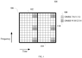
- FIG. 1 is a schematic diagram of a DMRS resource distribution manner 100 in a current LTE standard.
- the resource distribution manner shown in FIG. 1 supports single-user MIMO (Single-User MIMO, SU-MIMO) transmission of a maximum of eight symbol streams (also referred to as spatial streams or data streams), and the symbol streams respectively correspond to DMRS ports 7-14.
- the SU-MIMO currently supports orthogonal DMRS multiplexing for a maximum of eight data streams, and a DMRS pilot frequency occupies 24 resource elements (Resource Element, RE).
- Multi-user MIMO Multi-User MIMO, MU-MIMO
- a DMRS resource mapping manner and location are fixed.
- RB pair 106 including a resource block (Resource Block, RB) 102 and an RB 104
- a DMRS occupies 24 REs in total. These REs are distributed on six subcarriers (subcarriers 0, 1, 5, 6, 10, and 11 of each RB) in frequency domain and on four symbols (symbols 5, 6, 12, and 13 of each subframe) in time domain.
- Four REs distributed on a same subcarrier and occupied by the DRMS form one DMRS RE group, and therefore the 24 REs occupied by the DMRS may be divided into six DMRS RE groups.
- Each DMRS RE group can carry, in a code division multiplexing (Code Division Multiplexing, CDM) manner by using a maximum of four groups of orthogonal cover codes (Orthogonal Cover Code, OCC), DMRSs corresponding to four DMRS ports (or may be represented as CDM-4 in time domain).
- CDM Code Division Multiplexing
- OCC Orthogonal Cover Code
- DMRSs corresponding to four DMRS ports or may be represented as CDM-4 in time domain.
- each DMRS RE group in which REs are located is used to carry DMRSs of DMRS ports 7, 8, 11, and 13.
- each DMRS RE group in which REs are located is used to carry DMRSs of DMRS ports 9, 10, 12, and 14.
- Orthogonal cover codes of four REs in each DMRS RE group corresponding to each DMRS port are listed in the following Table 1.
- DMRSs of each DMRS port occupy three DMRS RE groups, and the three DMRS RE groups are distributed on three subcarriers. This design manner may be used to withstand channel frequency selectivity. In addition, four REs included in each DMRS RE group are distributed on four OFDM symbols. This design manner may be used to withstand channel time variation.
- the DMRS resource distribution manner shown in FIG. 1 is only one of current various DMRS resource distribution manners of LTE.
- different DMRS resource distribution manners may be used in different scenarios.
- a DMRS resource distribution manner in an MU-MIMO scenario may be different from a DMRS resource distribution manner in an SU-MIMO scenario.
- a DMRS resource distribution manner may vary with a maximum quantity of simultaneously scheduled symbol streams. Therefore, a person skilled in the art needs to understand that the foregoing DMRS resource distribution manner is not intended to limit the scope of the technical solutions provided in the embodiments of the present invention.
- another DMRS resource distribution manner may alternatively be used.
- mapping a DMRS on the last symbol of a subframe cannot ensure enough time for data demodulation (self-contained frame structure).
- the current RS mapping and configuration solution in which only a fixed mapping manner and a single function are available cannot satisfy the requirements of the future communications system, and is not applicable to a scenario in which different transmission features of a plurality of waveforms and ports in the system need to be compensated.
- the following solutions can be considered: irregular mapping of various RS ports in a pilot pattern, configuration of different port multiplexing manners, carrying various different functions by a pilot, configurable density of different ports, and the like.
- an embodiment of the present invention provides a reference signal sending solution.
- An RS in a system can be flexibly configured based on different scenarios and requirements by flexibly mapping an RS port in a pilot pattern, so as to improve spectral efficiency while achieving a higher transmission rate.
- a base station may determine a dedicated time-frequency resource of at least one second reference signal as a time-frequency resource used to carry a first reference signal, and then send the first reference signal by using the determined time-frequency resource. In this manner, the base station may use an idle RE in an RS pattern to transmit another RS signal simultaneously, thereby improving spectral efficiency while achieving a higher transmission rate.
- the first reference signal is a CSI-RS
- the second reference signal is a DMRS.
- the base station may multiplex the resource in the DMRS pattern design, that is, the DMRS and another RS signal (for example, a CSI-RS) can be mapped onto a same time domain and frequency domain resource.
- the base station may send an indication signal to indicate a type and a mapping location of another RS that multiplexes the DMRS resource. That is, a plurality of RSs may be multiplexed simultaneously, and a type, density, and a location of the RS may be indicated independently.
- a sending period of the indication signal is configurable, and the indication signal may be specifically sent in one of the following manners: radio resource control (Radio Resource Control, RRC), downlink control information (Downlink Control Information, DCI), media access control (Media Access Control, MAC), or the like. It may be learned that in the foregoing manner, the base station can dynamically configure an RS depending on a scenario.
- an idle RE in a DMRS pattern can be effectively used to transmit a CSI-RS signal simultaneously, so as to improve spectral efficiency while ensuring channel estimation and data demodulation performance, thereby achieving higher resource utilization.
- FIG. 2 is a schematic architecture diagram of a wireless communications system according to some embodiments of the present invention.
- a wireless communications network 200 includes base stations 201 to 203 and terminals 210 to 217.
- the base stations 201 to 203 may communicate with each other through backhaul (backhaul) links (as shown by straight lines among the base stations 201 to 203).
- the backhaul link may be a wired backhaul link (for example, an optical fiber or a copper cable) or a wireless backhaul link (for example, a microwave).
- the terminals 210 to 217 may communicate with the corresponding base stations 201 to 203 through radio links (as shown by fold lines among the base stations 201 to 203 and the terminals 210 to 217).
- the base stations 201 to 203 are configured to provide a wireless access service for the terminals 210 to 217.
- each base station corresponds to one service coverage area (referred to as a cell, as shown by each elliptic area in FIG. 2 ).
- a terminal that enters the area may communicate with the base station by using a wireless signal, so as to accept the wireless access service provided by the base station.
- Service coverage areas of the base stations may overlap.
- a terminal in an overlapping area may receive wireless signals from a plurality of base stations. Therefore, these base stations may coordinate with each other to provide a service for the terminal.
- the plurality of base stations may provide the service for the terminal in the overlapping area by using a coordinated multipoint (Coordinated multipoint, CoMP) technology.
- CoMP Coordinated multipoint
- a service coverage area of the base station 201 overlaps a service coverage area of the base station 202, and the terminal 213 is located in the overlapping area. Therefore, the terminal 213 may receive wireless signals from the base station 201 and the base station 202.
- the base station 201 and the base station 202 may coordinate with each other to provide a service for the terminal 213.
- a common overlapping area exists in the service coverage areas of the base stations 201, 202, and 203, and the terminal 214 is located in the overlapping area. Therefore, the terminal 214 may receive wireless signals from the base stations 201, 202, and 203.
- the base stations 201, 202, and 203 may coordinate with each other to provide a service for the terminal 214.
- a base station may also be referred to as a NodeB (NodeB), an evolved NodeB (evolved NodeB, eNodeB), an access point (Access Point, AP), or the like.
- NodeB NodeB
- eNodeB evolved NodeB
- Access Point Access Point
- base stations may be classified into a macro base station for providing a macro cell (Macro cell), a micro base station for providing a pico cell (Pico cell), a femto base station for providing a femto cell (Femto cell), and the like.
- a macro base station for providing a macro cell
- Micro cell a macro cell
- Pico cell a pico cell
- Femto base station for providing a femto cell
- another name may be used for a future base station.
- the terminals 210 to 217 may be various wireless communications devices having a wireless communication function, for example but not limited to, a mobile cellular phone, a cordless phone, a personal digital assistant (Personal Digital Assistant, PDA), a smartphone, a notebook computer, a tablet computer, a wireless data card, a wireless modem (Modulator demodulator, Modem), or a wearable device such as a smartwatch.
- a wireless communication function for example but not limited to, a mobile cellular phone, a cordless phone, a personal digital assistant (Personal Digital Assistant, PDA), a smartphone, a notebook computer, a tablet computer, a wireless data card, a wireless modem (Modulator demodulator, Modem), or a wearable device such as a smartwatch.
- IOT Internet of Things
- these devices can access a wireless communications network and accept remote control.
- This type of device is configured with a wireless communication unit and therefore has the wireless communication function. Therefore, this type of device is also a kind of wireless communications device.
- the terminals 210 to 217 may alternatively be referred to as mobile stations, mobile devices, mobile terminals, wireless terminals, handheld devices, clients, or the like.
- the base stations 201 to 203 and the terminals 210 to 217 each may be configured with a plurality of antennas to support a MIMO technology. Further, the base stations 201 to 203 and the terminals 210 to 217 may support an SU-MIMO technology and an MU-MIMO technology, and MU-MIMO may be implemented by using a space division multiple access (Space Division Multiple Access, SDMA) technology.
- SDMA Space Division Multiple Access
- the base stations 201 to 203 and the terminals 210 to 217 may further flexibly support a single-input single-output (Single Input Single Output, SISO) technology, a single-input multiple-output (Single Input Multiple Output, SIMO) technology, and a multiple-input single-output (Multiple Input Single Output, MISO) technology, so as to implement various diversity (for example but not limited to, transmit diversity and receive diversity) and multiplexing technologies.
- the diversity technology may include, for example but not limited to, a transmit diversity (Transmit Diversity, TD) technology and a receive diversity (Receive Diversity, RD) technology.
- the multiplexing technology may be a spatial multiplexing (Spatial Multiplexing) technology.
- the foregoing technologies may further include a plurality of implementation solutions.
- the transmit diversity technology may include diversity manners such as space time transmit diversity (Space-Time Transmit Diversity, STTD), space-frequency transmit diversity (Space-Frequency Transmit Diversity, SFTD), time switched transmit diversity (Time Switched Transmit Diversity, TSTD), frequency switched transmit diversity (Frequency Switch Transmit Diversity, FSTD), orthogonal transmit diversity (Orthogonal Transmit Diversity, OTD), cyclic delay diversity (Cyclic Delay Diversity, CDD), and diversity manners obtained after derivation, evolution, and combination of the foregoing diversity manners.
- transmit diversity manners such as space time block coding (Space Time Block Coding, STBC), space frequency block coding (Space Frequency Block Coding, SFBC), and CDD are used in a current LTE standard.
- the base stations 201 to 203 and the terminals 210 to 217 may communicate with each other by using various wireless communications technologies, for example but not limited to, a time division multiple access (Time Division Multiple Access, TDMA) technology, a frequency division multiple access (Frequency Division Multiple Access, FDMA) technology, a code division multiple access (Code Division Multiple Access, CDMA) technology, a time division-synchronous code division multiple access (Time Division-Synchronous Code Division Multiple Access, TD-SCDMA) technology, an orthogonal frequency division multiple access (Orthogonal FDMA, OFDMA) technology, a single carrier frequency division multiple access (Single Carrier FDMA, SC-FDMA) technology, a space division multiple access (Space Division Multiple Access, SDMA) technology, and technologies evolving and derived from these technologies.
- TDMA time division multiple access
- FDMA frequency division multiple access
- CDMA code division multiple access
- TD-SCDMA time division-synchronous code division multiple access
- OFDMA orthogonal frequency division multiple access
- radio access technologies Radio Access Technology, RAT
- the foregoing wireless communications technologies are adopted in many wireless communications standards, so as to construct various currently well-known wireless communications systems (or networks), including but not limited to a global system for mobile communications (Global System for Mobile Communications, GSM), CDMA 2000, wideband CDMA (Wideband CDMA, WCDMA), Wi-Fi defined in the 802.11 series standards, worldwide interoperability for microwave access (Worldwide Interoperability for Microwave Access, WiMAX), LTE, LTE-A, and systems evolving from these wireless communications systems.
- GSM Global System for Mobile Communications
- CDMA 2000 Wideband CDMA
- WCDMA wideband CDMA
- Wi-Fi defined in the 802.11 series standards
- worldwide interoperability for microwave access Worldwide Interoperability for Microwave Access, WiMAX
- LTE Long Term Evolution
- LTE-A Long Term Evolution-Advance
- systems evolving from these wireless communications systems including but not limited to a global system for mobile communications (Global System for Mobile Communications, GSM), CDMA 2000
- the wireless communications network 200 shown in FIG. 2 is merely an example, and is not intended to limit the technical solutions of the present invention.
- the wireless communications network 200 may further include another device, and a quantity of base stations and a quantity of terminals may be configured as required.
- FIG. 3 is a flowchart of a reference signal sending method according to some embodiments of the present invention.
- a process shown in FIG. 3 may be implemented by a base station.
- the base station shown in FIG. 2 may be configured with a physical or functional module to perform the process shown in FIG. 3 , and the functional module configured to perform the process may be implemented by using hardware, software programming, or a combination of software and hardware.
- the process includes the following steps:
- the base station is configured to perform the process shown in FIG. 3 .
- the first reference signal may be carried and sent by using the dedicated time-frequency resource of the at least one second reference signal, so that RS signals such as a DMRS and a CSI-RS can be mapped onto a same time domain and frequency domain resource, and an RS of a system can be flexibly configured based on different scenarios and requirements to effectively use the time-frequency resource.
- RS signals such as a DMRS and a CSI-RS
- an RS of a system can be flexibly configured based on different scenarios and requirements to effectively use the time-frequency resource.
- a resource unit Similar to an RB, an RB pair (RB pair), a subframe, or another resource structure in an LTE standard, a resource unit (Resource Unit) is provided in some embodiments of the present invention.
- the resource unit may be used as a basic unit for performing resource allocation for a scheduled user, or may be used to describe arrangement manners of various reference signals.
- FIG. 4 is a schematic structural diagram of a resource unit according to some embodiments of the present invention.
- the resource unit 400 occupies a plurality of consecutive subcarriers in frequency domain and a plurality of consecutive symbols (OFDM symbols) in time domain.
- a minimum resource unit in a resource unit is an RE 401, and each RE occupies one subcarrier in frequency domain and one symbol in time domain.
- the resource unit 400 usually includes a plurality of REs. Similar to the RB and the RB pair in the LTE standard, the resource unit shown in FIG. 4 may be used as a basic unit for performing resource allocation for a scheduled user, or may be used to describe arrangement manners of various reference signals.
- the determining a time-frequency resource used to carry a first reference signal may be specifically determining the time-frequency resource used to carry the first reference signal in a resource unit in which the first reference signal is located.
- the first reference signal is a CSI-RS
- the second reference signal is a DMRS.
- two or more reference signals of a same type or different types may be mapped onto a same time domain and frequency domain resource.
- one first reference signal and one second reference signal are mainly used as examples for description in this application.
- the time-frequency resource determined in step 301 is within a scheduling period of the first reference signal, and the second reference signal is not scheduled within the scheduling period.
- the first reference signal is a CSI-RS
- the second reference signal is a DMRS.
- the base station may indicate, by sending a resource configuration indication, a type and a mapping location of a reference signal that multiplexes the time-frequency resource.
- the base station may perform the following process A:
- the terminal can determine, based on the resource configuration indication sent by the base station, the time-frequency resource used to carry the first reference signal, and then obtain the first reference signal by using the determined time-frequency resource.
- the process including step Al and step A2 may be performed by the base station before the base station determines, as described in step 301 in the process shown in FIG. 3 , the time-frequency resource used to carry the first reference signal.
- the terminal after receiving the first reference signal sent by the base station, the terminal can obtain the first reference signal from the time-frequency resource determined based on the resource configuration indication.
- the resource configuration indication may include a reference signal identifier and corresponding resource configuration information.
- the reference signal identifier may be specifically, for example but not limited to, an antenna port number.
- the base station may alternatively indicate, by sending a scheduling indication, a type and a mapping location of a reference signal that multiplexes the time-frequency resource.
- the base station may perform the following process B:
- the terminal can determine, based on the scheduling indication sent by the base station, that the base station is to invoke the first reference signal, and determine the time-frequency resource used to carry the first reference signal, and then obtain the first reference signal by using the determined time-frequency resource.
- step B1 and step B2 may alternatively be performed by the base station before the base station determines, as described in step 301 in the process shown in FIG. 3 , the time-frequency resource used to carry the first reference signal.
- the terminal can obtain the first reference signal based on the scheduling indication after receiving the first reference signal sent by the base station.
- the scheduling indication may include a reference signal identifier. Similar to the foregoing description, the reference signal identifier may be specifically, for example but not limited to, an antenna port number.
- the base station may show reference signal invoking by using an antenna port. For example, invoking an antenna port 1 means invoking a reference signal corresponding to the antenna port 1.
- the time-frequency resource of the first reference signal may be dynamically indicated.
- the time-frequency resource of the first reference signal is indicated by using physical layer signaling described below.
- a dynamic indication of the time-frequency resource of the first reference signal includes a reference signal identifier and corresponding resource configuration information.
- the reference signal identifier may be specifically, for example but not limited to, an antenna port number.
- various types of RSs may be multiplexed simultaneously.
- a type, density, and a location of the RS may be specifically indicated by the base station simultaneously or separately.
- both the resource configuration indication and the scheduling indication may be sent by using but not limited to one of the following signaling: physical layer signaling, media access control layer signaling, and radio resource control signaling.
- the physical layer signaling is also referred to as layer 1 (Layer 1, L1) signaling, and may usually be carried in a control part of a physical layer frame.
- a typical example of the L1 signaling is downlink control information (Downlink Control Information, DCI) carried on a physical downlink control channel (Physical Downlink Control Channel, PDCCH) defined in the LTE standard.
- DCI Downlink Control Information
- PDCCH Physical Downlink Control Channel
- the L1 signaling may alternatively be carried by a data part of the physical layer frame. It is not difficult to learn that a sending period or a signaling period of the L1 signaling is usually a period of the physical layer frame. Therefore, the signaling is usually used to implement some dynamic control to transfer some frequently changed information. For example, resource allocation information may be transferred by using the physical layer signaling.
- the media access control (Media Access Control, MAC) layer signaling is layer 2 (Layer 2) signaling, and may usually be carried in, for example but not limited to, a frame header of a layer 2 frame.
- the frame header may further carry, for example but not limited to, information such as a source address and a destination address.
- the layer 2 frame usually further includes a frame body.
- the L2 signaling may alternatively be carried in the frame body of the layer 2 frame.
- a typical example of the layer 2 signaling is signaling carried in a frame control (Frame Control) field in a frame header of a MAC frame in the 802.11 series standard, or a MAC control entity (Control Entity, MAC) defined in some protocols.
- the layer 2 frame may usually be carried in the data part of the physical layer frame.
- the resource indication information may alternatively be sent by using another layer 2 signaling different from the media access control layer signaling.
- the radio resource control (Radio Resource Control, RRC) signaling is layer 3 (Layer 3) signaling, and is usually some control messages.
- the L3 signaling may usually be carried in a frame body of a layer 2 frame.
- a sending period or a control period of the L3 signaling is usually relatively long, and the L3 signaling is applicable to sending of some information that does not change frequently.
- the L3 signaling is usually used to carry some configuration information.
- the resource indication information may alternatively be sent by using another layer 3 signaling different from the RRC signaling.
- the resource configuration indication is used to configure the time-frequency resource of the first reference signal, and the scheduling indication is used to schedule the first reference signal
- the resource configuration indication is suitable to be sent by using the MAC layer signaling or the RRC signaling
- the scheduling indication is suitable to be sent by using the physical layer signaling. If the solution of dynamically indicating the time-frequency resource of the first reference signal is used, that is, one piece of dynamic configuration signaling is used to configure the time-frequency resource of the first reference signal and schedule the first reference signal, the indication is suitable to be sent by using the physical layer signaling.
- sending periods of both the resource configuration indication and the scheduling indication are configurable.
- the sending period may be a preset initial value or may be configured in real time by the base station.
- the base station may send a resource configuration indication or a scheduling indication to the terminal.
- FIG. 5(a) , FIG. 5(b) , FIG. 5(c) , and FIG. 5(d) are schematic diagrams of RS mapping locations in different scenarios according to some embodiments of the present invention.
- Each DMRS port occupies six REs, and the DMRS ports include a DMRS port 1 that is invoked, and DMRS ports 2, 3, and 4 that are not invoked.
- the invoked DMRS port 1 occupies REs distributed on three subcarriers (subcarriers 0, 4, and 8) in frequency domain and on two symbols (symbols 3 and 4) in time domain.
- the DMRS port 2 that is not invoked is configured to occupy REs distributed on three subcarriers (subcarriers 1, 5, and 9) in frequency domain and on two symbols (symbols 3 and 4) in time domain.
- the DMRS port 3 that is not invoked is configured to occupy REs distributed on three subcarriers (subcarriers 2, 6, and 10) in frequency domain and on two symbols (symbols 3 and 4) in time domain.
- the DMRS port 3 that is not invoked is configured to occupy REs on three subcarriers (subcarriers 3, 7, and 11) distributed in frequency domain and on two symbols (symbols 3 and 4) in time domain. Because the DMRS ports 2, 3, and 4 are not invoked, REs corresponding to the DMRS ports 2, 3, and 4 are idle.
- FIG. 5(a) is a schematic diagram of an RS mapping location in a scenario according to some embodiments of the present invention.
- a CRS-RS 9 (equivalent to the foregoing first reference signal), namely, a CSI-RS port 9, is configured to occupy six idle REs in the assumed DMRS pattern. These REs are distributed on three subcarriers (subcarriers 2, 6, and 10) in frequency domain and on two symbols (symbols 3 and 4) in time domain. It can be learned that the CRS-RS 9 and the DMRS port 3 are mapped onto a same time domain resource, which is equivalent to that a dedicated time-frequency resource corresponding to the DMRS port 3 is configured to carry the CRS-RS 9.
- FIG. 5(b) is a schematic diagram of an RS mapping location in a scenario according to some embodiments of the present invention.
- a CRS 8 (equivalent to the foregoing first reference signal), namely, a CRS port 8 is configured to occupy six idle REs in the assumed DMRS pattern. These REs are distributed on three subcarriers (subcarriers 1, 5, and 9) in frequency domain and on two symbols (symbols 3 and 4) in time domain. It can be learned that the CRS 8 and the DMRS port 2 are mapped onto a same time domain resource, which is equivalent to that a dedicated time-frequency resource corresponding to the DMRS port 2 is configured to carry the CRS 8.
- FIG. 5(c) is a schematic diagram of an RS mapping location in another scenario according to some embodiments of the present invention.
- This example scenario may be considered as a combination of the scenarios shown in FIG. 5(a) and FIG. 5(b) .
- a CRS-RS 9 (equivalent to a first reference signal) is configured to occupy six REs corresponding to the DMRS port 3 (equivalent to a second reference signal), and a CRS 8 (equivalent to another first reference signal) is configured to occupy six REs corresponding to the DMRS port 2.
- the CRS-RS 9 and the DMRS port 3 are mapped onto a same time domain resource, and the CRS 8 and the DMRS port 2 are mapped onto a same time domain resource.
- FIG. 5(d) is a schematic diagram of an RS mapping location in still another scenario according to some embodiments of the present invention.
- a CRS 8 (equivalent to a first reference signal) is configured to occupy six idle REs in the assumed DMRS pattern. These REs are distributed on six subcarriers (subcarriers 1, 2, 5, 6, 9, and 10) in frequency domain and on one symbol (symbol 3) in time domain.
- a CRS-RS 9 (equivalent to another first reference signal) is configured to occupy another six idle REs in the assumed DMRS pattern. These REs are distributed on three subcarriers (subcarriers 1, 2, 5, 6, 9, and 10) in frequency domain and on one symbol (symbol 4) in time domain.
- the CRS 8 and the CSR-RS 9 are configured to occupy 12 REs corresponding to the DMRS port 2 and the DMRS port 3, which is equivalent to that dedicated time-frequency resources corresponding to the DMRS port 2 and the DMRS port 3 are configured to carry the CRS 8 and the CSR-RS 9.
- the CRS 8 may alternatively be another reference signal, for example, a CSI-RS 20, namely, a CSI-RS port 20.
- the CSI-RS 9 may alternatively be another reference signal, for example, a CRS 30, namely, a CRS port 30.
- a time-frequency resource of a dedicated DMRS that is not occupied may be allocated to one or more other reference signals, and types of these reference signals may be different from that of the DMRS.
- the reference signal sending technical solution provided in the foregoing embodiment of the present invention equivalently provides a pilot design and mapping solution in which a resource can be multiplexed, and introduces a change of related signaling.
- RS signals may be mapped onto a same time domain and frequency domain resource.
- the base station may indicate, by sending an indication, the type and the mapping location of the RS that multiplexes a time domain and frequency domain resource.
- the type, the density, and the location of the RS may be separately indicated, and the indication may be sent by using RRC, DCI, MAC, or the like.
- a configuration period of the indication may be a preset initial value, or may be configured in real time.
- the reference signal sending technical solution provided in this embodiment of the present invention is configured by using signaling of the base station, so that the terminal can use an idle RE in an RS pattern to transmit another RS signal simultaneously, effectively using the idle RE in the RS pattern to transmit another RS signal simultaneously and improving spectral efficiency while achieving a higher transmission rate.
- the base station may dynamically configure, based on different communication scenarios, a time-frequency resource used to carry a reference signal, thereby greatly improving spectral efficiency while ensuring channel estimation and data demodulation performance.
- interference among terminals in a multi-terminal pairing system can be effectively suppressed, thereby resolving a problem of heavy indication overheads during rate matching (Rate Matching, RM) in a scenario with a larger quantity of ports.
- RM rate Matching
- FIG. 6 is a flowchart of a reference signal receiving method according to some embodiments of the present invention.
- a process shown in FIG. 6 may be implemented by a terminal.
- the terminal shown in FIG. 2 may be configured with a physical or functional module configured to perform the process shown in FIG. 6
- the functional module configured to perform the process may be implemented by using hardware, software programming, or a combination of software and hardware.
- the process includes the following steps:
- Step 601 Determine a time-frequency resource used to carry a first reference signal, where the time-frequency resource is a dedicated time-frequency resource of at least one second reference signal.
- Step 602 Obtain the first reference signal by using the determined time-frequency resource.
- the terminal may receive a resource configuration indication used to indicate the time-frequency resource that carries the first reference signal, where the time-frequency resource is the dedicated time-frequency resource of the at least one second reference signal.
- the terminal may receive the resource configuration indication sent by a base station, so as to determine, based on the resource configuration indication, the time-frequency resource used to carry the first reference signal.
- the terminal may receive a scheduling indication used to indicate that the first reference signal is to be scheduled, where the time-frequency resource that carries the first reference signal is the dedicated time-frequency resource of the at least one second reference signal.
- the terminal may receive the scheduling indication sent by a base station, so as to determine, based on the scheduling indication, that the base station is to schedule the first reference signal, and determine the time-frequency resource used to carry the first reference signal.
- the time-frequency resource determined in step 601 is within a scheduling period of the first reference signal, and the second reference signal is not scheduled within the scheduling period.
- the first reference signal is a CSI-RS
- the second reference signal is a DMRS
- a specific implementation process in which the terminal determines the time-frequency resource used to carry the first reference signal and obtains the first reference signal by using the determined time-frequency resource may be adjusted adaptively based on the foregoing reference signal sending method process described on the base station side in the present invention.
- a specific implementation may be obtained based on the described method embodiment on the base station side in the foregoing embodiment of the present invention, and details are not described herein.
- this application further provides a reference signal sending apparatus.
- a functional module of the apparatus may be specifically implemented by using hardware, software, or a combination of software and hardware, and the apparatus may be deployed in a base station.
- the apparatus may be deployed in the base station in the communications system shown in FIG. 2 .
- FIG. 7 is a schematic structural diagram of a reference signal sending apparatus according to some embodiments of the present invention. As shown in FIG. 7 , the apparatus includes:
- a resource configuration indication apparatus is further provided.
- the apparatus may be configured to generate and send a resource configuration indication used to indicate the time-frequency resource that carries the first reference signal, where the time-frequency resource is the dedicated time-frequency resource of the at least one second reference signal.
- a scheduling indication apparatus is further provided.
- the apparatus may be configured to generate and send a scheduling indication used to indicate that the first reference signal is to be scheduled, where the time-frequency resource that carries the first reference signal is the dedicated time-frequency resource of the at least one second reference signal.
- both the resource configuration indication apparatus and the scheduling indication apparatus provided in some embodiments of the present invention may be implemented as functional modules in the foregoing reference signal sending apparatus, so that a terminal can determine, based on the received resource configuration indication or scheduling indication, the time-frequency resource that carries the first reference signal.
- the determined time-frequency resource is within a scheduling period of the first reference signal, and the second reference signal is not scheduled within the scheduling period.
- the first reference signal is a CSI-RS
- the second reference signal is a DMRS
- the apparatus provided in the foregoing embodiment of the present invention and the method embodiment on the base station side provided in the foregoing embodiment of the present invention have similar principles for problem resolving. Therefore, mutual reference may be made between a specific implementation of the apparatus provided in the foregoing embodiment of the present invention and the implementation of the method on the base station side provided in the foregoing embodiment of the present invention. Repeated content is not described herein again.
- this application further provides a reference signal receiving apparatus.
- a functional module of the apparatus may be specifically implemented by using hardware, software, or a combination of software and hardware, and the apparatus may be deployed in a terminal.
- the apparatus may be deployed in the terminal in the communications system shown in FIG. 2 .
- FIG. 8 is a schematic structural diagram of a reference signal receiving apparatus according to some embodiments of the present invention. As shown in FIG. 8 , the apparatus includes:
- a resource configuration indication receiving apparatus is further provided in some embodiments of the present invention.
- the apparatus may be configured to receive a resource configuration indication used to indicate the time-frequency resource that carries the first reference signal, where the time-frequency resource is the dedicated time-frequency resource of the at least one second reference signal.
- a scheduling indication receiving apparatus is further provided.
- the apparatus may be configured to receive a scheduling indication used to indicate that the first reference signal is to be scheduled, where the time-frequency resource that carries the first reference signal is the dedicated time-frequency resource of the at least one second reference signal.
- both the resource configuration indication receiving apparatus and the scheduling indication receiving apparatus may be implemented as functional modules in the foregoing reference signal sending apparatus, so that a terminal can determine, based on the received resource configuration indication or scheduling indication, the time-frequency resource that carries the first reference signal.
- the determined time-frequency resource is within a scheduling period of the first reference signal, and the second reference signal is not scheduled within the scheduling period.
- the first reference signal is a CSI-RS
- the second reference signal is a DMRS
- the apparatus provided in the foregoing embodiment of the present invention and the method embodiment on a terminal side provided in the foregoing embodiment of the present invention have similar principles for problem resolving. Therefore, mutual reference may be made between a specific implementation of the apparatus provided in the foregoing embodiment of the present invention and the implementation of the method on the terminal side provided in the foregoing embodiment of the present invention. Repeated content is not described herein again.
- Module division in the embodiments of this application is an example, and is merely a kind of logical function division. In actual implementation, there may be another division manner.
- functional modules in the embodiments of this application may be integrated into one processor, or may exist alone physically, or two or more modules may be integrated into one module.
- the integrated module may be implemented in a form of hardware, or may be implemented in a form of a software functional module.
- FIG. 9 is a schematic structural diagram of a base station according to some embodiments of the present invention.
- the base station 900 may include a processor 901.
- the processor 901 may be a central processing module (central processing unit, CPU), a digital processing module, or the like.
- the base station 900 may further include a transceiver 902.
- the processor 901 is configured to determine a time-frequency resource used to carry a first reference signal, where the time-frequency resource is a dedicated time-frequency resource of at least one second reference signal; and the transceiver 902 is configured to send the first reference signal by using the time-frequency resource determined by the processor 901.
- the processor 901 and the transceiver 902 are specifically configured to perform the method on the base station side provided in the foregoing embodiment of the present invention. Details are not described herein.
- the base station 900 may further include a memory configured to store a program executed by the processor 901.
- the memory may be a nonvolatile memory, such as a hard disk drive (hard disk drive, HDD) or a solid-state drive (solid-state drive, SSD), or may be a volatile memory (volatile memory), such as a random access memory (random-access memory, RAM).
- the memory is, but not limited to, any other medium that can be configured to carry or store desired program code in a form of an instruction or a data structure and can be accessed by a computer.
- a specific connection medium between the processor 901 and the transceiver 902 is not limited.
- the processor 901 and the transceiver 902 are connected via a bus in FIG. 9 .
- a hollow double-arrow line is used to indicate the bus, but this does not indicate that there is only one bus or only one type of bus. Connection manners among other components are merely examples and are not restrictive.
- the bus may be classified into an address bus, a data bus, a control bus, and the like.
- An embodiment of the present invention further provides a readable storage medium.
- the readable storage medium is configured to store a software instruction that needs to be executed by the processor, and the software instruction includes a program that needs to be executed by the processor.
- FIG. 10 is a schematic structural diagram of a terminal according to some embodiments of the present invention.
- the terminal 1000 may include a processor 1001.
- the processor 1001 may be a central processing module (central processing unit, CPU), a digital processing module, or the like.
- the terminal 1000 may further include a transceiver 1002.
- the processor 1001 is configured to determine a time-frequency resource used to carry a first reference signal, where the time-frequency resource is a dedicated time-frequency resource of a second reference signal; and obtain the first reference signal by using the transceiver 1002 using the determined time-frequency resource.
- the processor 1001 and the transceiver 1002 are specifically configured to perform the method on the terminal side provided in the foregoing embodiment of the present invention. Details are not described herein.
- the terminal 1000 may further include a memory configured to store a program executed by the processor 1001.
- the memory may be a nonvolatile memory, such as a hard disk drive (hard disk drive, HDD) or a solid-state drive (solid-state drive, SSD), or may be a volatile memory (volatile memory), such as a random access memory (random-access memory, RAM).
- the memory is, but not limited to, any other medium that can be configured to carry or store desired program code in a form of an instruction or a data structure and can be accessed by a computer.
- a specific connection medium between the processor 1001 and the transceiver 1002 is not limited.
- the processor 1001 and the transceiver 1002 are connected via a bus in FIG. 10 .
- a hollow double-arrow line is used to indicate the bus, but this does not indicate that there is only one bus or only one type of bus. Connection manners among other components are merely examples and are not restrictive.
- the bus may be classified into an address bus, a data bus, a control bus, and the like.
- An embodiment of the present invention further provides a readable storage medium.
- the readable storage medium is configured to store a software instruction that needs to be executed by the processor, and the software instruction includes a program that needs to be executed by the processor.
- this application may be provided as a method, a system, or a program product. Therefore, this application may use a form of hardware only embodiments, software only embodiments, or embodiments with a combination of software and hardware. Moreover, this application may use a form of a computer program product that is implemented on one or more usable storage media (including but not limited to a disk memory, a CD-ROM, an optical memory, and the like) that include computer usable program code.
- usable storage media including but not limited to a disk memory, a CD-ROM, an optical memory, and the like
- program instructions may be provided for a general-purpose computer, a dedicated computer, an embedded processor, or a processor of another programmable data processing device to generate a machine, so that the instructions executed by a computer or a processor of another programmable data processing device generate an apparatus for implementing a specific function in one or more processes in the flowcharts and/or in one or more blocks in the block diagrams.
- program instructions may be stored in a readable memory that can instruct a computer or another programmable data processing device to work in a specific manner, so that the instructions stored in the readable memory generate an artifact that includes an instruction apparatus.
- the instruction apparatus implements a specific function in one or more processes in the flowcharts and/or in one or more blocks in the block diagrams.
Landscapes
- Engineering & Computer Science (AREA)
- Signal Processing (AREA)
- Computer Networks & Wireless Communication (AREA)
- Mobile Radio Communication Systems (AREA)
Applications Claiming Priority (2)
| Application Number | Priority Date | Filing Date | Title |
|---|---|---|---|
| CN201710061787.6A CN108365933B (zh) | 2017-01-26 | 2017-01-26 | 一种发送参考信号的方法及装置 |
| PCT/CN2017/119430 WO2018137464A1 (zh) | 2017-01-26 | 2017-12-28 | 一种发送参考信号的方法及装置 |
Publications (3)
| Publication Number | Publication Date |
|---|---|
| EP3553987A1 EP3553987A1 (en) | 2019-10-16 |
| EP3553987A4 EP3553987A4 (en) | 2020-01-01 |
| EP3553987B1 true EP3553987B1 (en) | 2021-09-01 |
Family
ID=62979140
Family Applications (1)
| Application Number | Title | Priority Date | Filing Date |
|---|---|---|---|
| EP17893822.1A Active EP3553987B1 (en) | 2017-01-26 | 2017-12-28 | Method and apparatus for sending reference signal |
Country Status (4)
| Country | Link |
|---|---|
| US (1) | US11101957B2 (zh) |
| EP (1) | EP3553987B1 (zh) |
| CN (1) | CN108365933B (zh) |
| WO (1) | WO2018137464A1 (zh) |
Families Citing this family (4)
| Publication number | Priority date | Publication date | Assignee | Title |
|---|---|---|---|---|
| US11658780B2 (en) * | 2019-01-09 | 2023-05-23 | Qualcomm Incorporated | Demodulation reference signal multiplexing scheme selection for uplink transmission |
| EP4085563A4 (en) * | 2020-01-03 | 2023-03-29 | ZTE Corporation | MODIFICATION OF REFERENCE SIGNAL PARAMETERS FOR IMPROVED CHANNEL ESTIMATION IN WIRELESS COMMUNICATION SYSTEMS |
| EP4218328A1 (en) * | 2020-10-16 | 2023-08-02 | Nokia Technologies Oy | Dedicated resource configuration for transmission of demodulation reference signal |
| CN113890707B (zh) * | 2021-09-26 | 2023-05-30 | 中国联合网络通信集团有限公司 | 通信方法、装置、设备以及存储介质 |
Family Cites Families (15)
| Publication number | Priority date | Publication date | Assignee | Title |
|---|---|---|---|---|
| CN101626620B (zh) * | 2009-08-07 | 2014-03-12 | 中兴通讯股份有限公司 | 一种参考信号的发送方法 |
| CN102118340A (zh) * | 2010-01-06 | 2011-07-06 | 中兴通讯股份有限公司 | 信道状态信息参考信号的映射方法及发送方法及发送系统 |
| JP5283669B2 (ja) * | 2010-08-10 | 2013-09-04 | 株式会社エヌ・ティ・ティ・ドコモ | 送信機、受信機及び無線通信方法 |
| KR101966128B1 (ko) * | 2011-03-11 | 2019-04-05 | 엘지전자 주식회사 | 하향링크 신호 수신 방법 및 전송 방법과, 수신 장치 및 전송 장치 |
| US20140219237A1 (en) * | 2011-06-07 | 2014-08-07 | Broadcom Corporation | Method and Apparatus for Establishing a Time-Frequency Reference Signal Pattern Configuration in a Carrier Extension or Carrier Segment |
| WO2013069345A1 (ja) | 2011-11-07 | 2013-05-16 | 株式会社エヌ・ティ・ティ・ドコモ | 無線通信システム、基地局装置、移動端末装置、及び干渉測定方法 |
| US9198070B2 (en) * | 2012-05-14 | 2015-11-24 | Google Technology Holdings LLC | Radio link monitoring in a wireless communication device |
| US20130343299A1 (en) * | 2012-06-21 | 2013-12-26 | Samsung Electronics Co., Ltd | Method for cqi feedback without spatial feedback (pmi/ri) for tdd coordinated multi-point and carrier aggregation scenarios |
| CN103582141A (zh) * | 2012-07-31 | 2014-02-12 | 华为技术有限公司 | 传输参考信号的方法、用户设备和网络侧设备 |
| CN103891371B (zh) * | 2012-08-13 | 2018-04-20 | 华为技术有限公司 | 一种配置导频信号的方法、服务基站和用户设备 |
| JP6091816B2 (ja) | 2012-09-11 | 2017-03-08 | 株式会社Nttドコモ | 無線通信システム、基地局装置、移動端末装置、及び干渉測定方法 |
| US9554381B2 (en) * | 2012-09-24 | 2017-01-24 | Lg Electronics Inc. | Method and apparatus for transmitting or receiving an additional demodulation reference signal based on a channel state information reference signal resource pattern |
| US9769807B2 (en) * | 2012-09-28 | 2017-09-19 | Telefonaktiebolaget Lm Ericsson (Publ) | User equipment, radio network node and methods therein |
| CN104160766B (zh) * | 2013-01-24 | 2019-04-05 | 华为技术有限公司 | 用于传输参考信号的方法、基站和用户设备 |
| WO2017008235A1 (en) * | 2015-07-14 | 2017-01-19 | Nec Corporation | Method and apparatus for downlink transmission power configuration and signal detection |
-
2017
- 2017-01-26 CN CN201710061787.6A patent/CN108365933B/zh active Active
- 2017-12-28 EP EP17893822.1A patent/EP3553987B1/en active Active
- 2017-12-28 WO PCT/CN2017/119430 patent/WO2018137464A1/zh unknown
-
2019
- 2019-07-26 US US16/523,737 patent/US11101957B2/en active Active
Also Published As
| Publication number | Publication date |
|---|---|
| EP3553987A1 (en) | 2019-10-16 |
| CN108365933A (zh) | 2018-08-03 |
| CN108365933B (zh) | 2023-07-18 |
| US20190349168A1 (en) | 2019-11-14 |
| US11101957B2 (en) | 2021-08-24 |
| WO2018137464A1 (zh) | 2018-08-02 |
| EP3553987A4 (en) | 2020-01-01 |
Similar Documents
| Publication | Publication Date | Title |
|---|---|---|
| CN108476049B (zh) | 用于信道状态信息参考信号(csi-rs)的方法和装置 | |
| US10448408B2 (en) | Method and apparatus for coordinating multi-point transmission in advanced wireless systems | |
| CN107666341B (zh) | 用大规模阵列天线的移动通信系统中csi-rs端口共享的参考信号配置的方法和装置 | |
| JP6977920B2 (ja) | チャネル状態情報報告バンドの設定方法及び通信装置 | |
| US11005625B2 (en) | Reference signal indication method and apparatus to improve spectrum efficiency | |
| KR20190085527A (ko) | 개선된 무선 통신 시스템에서 csi 보고를 위한 코드북 | |
| US11101957B2 (en) | Reference signal sending method and apparatus | |
| EP3086481A1 (en) | Communication method and apparatus in full-dimensional multiple-input multiple-output mobile communication system | |
| US11190321B2 (en) | Reference signal transmission method, network side apparatus, and user equipment | |
| JP6293144B2 (ja) | 制御情報処理方法及び装置 | |
| WO2020151531A1 (zh) | 参考信号的传输方法及装置 | |
| WO2018142199A1 (en) | Mixed space time and space frequency block coding | |
| US11784770B2 (en) | Method and apparatus for sending reference signal, and method and apparatus for obtaining reference signal | |
| WO2014113938A1 (en) | Radio base station and method for precoding signal | |
| EP3672317B1 (en) | Method for channel measurement | |
| EP3562084B1 (en) | Method for sending reference signal, method for receiving reference signal, and related device | |
| CN109842474B (zh) | 传输指示方法、设备及系统、存储介质 | |
| WO2018082394A1 (zh) | 一种发送和获取参考信号的方法和装置 | |
| EP3528397B1 (en) | Precoding configuration method, device and system |
Legal Events
| Date | Code | Title | Description |
|---|---|---|---|
| STAA | Information on the status of an ep patent application or granted ep patent |
Free format text: STATUS: THE INTERNATIONAL PUBLICATION HAS BEEN MADE |
|
| PUAI | Public reference made under article 153(3) epc to a published international application that has entered the european phase |
Free format text: ORIGINAL CODE: 0009012 |
|
| STAA | Information on the status of an ep patent application or granted ep patent |
Free format text: STATUS: REQUEST FOR EXAMINATION WAS MADE |
|
| 17P | Request for examination filed |
Effective date: 20190710 |
|
| AK | Designated contracting states |
Kind code of ref document: A1 Designated state(s): AL AT BE BG CH CY CZ DE DK EE ES FI FR GB GR HR HU IE IS IT LI LT LU LV MC MK MT NL NO PL PT RO RS SE SI SK SM TR |
|
| AX | Request for extension of the european patent |
Extension state: BA ME |
|
| A4 | Supplementary search report drawn up and despatched |
Effective date: 20191203 |
|
| RIC1 | Information provided on ipc code assigned before grant |
Ipc: H04L 5/00 20060101AFI20191127BHEP |
|
| DAV | Request for validation of the european patent (deleted) | ||
| DAX | Request for extension of the european patent (deleted) | ||
| GRAP | Despatch of communication of intention to grant a patent |
Free format text: ORIGINAL CODE: EPIDOSNIGR1 |
|
| STAA | Information on the status of an ep patent application or granted ep patent |
Free format text: STATUS: GRANT OF PATENT IS INTENDED |
|
| INTG | Intention to grant announced |
Effective date: 20210414 |
|
| GRAS | Grant fee paid |
Free format text: ORIGINAL CODE: EPIDOSNIGR3 |
|
| GRAA | (expected) grant |
Free format text: ORIGINAL CODE: 0009210 |
|
| STAA | Information on the status of an ep patent application or granted ep patent |
Free format text: STATUS: THE PATENT HAS BEEN GRANTED |
|
| AK | Designated contracting states |
Kind code of ref document: B1 Designated state(s): AL AT BE BG CH CY CZ DE DK EE ES FI FR GB GR HR HU IE IS IT LI LT LU LV MC MK MT NL NO PL PT RO RS SE SI SK SM TR |
|
| REG | Reference to a national code |
Ref country code: GB Ref legal event code: FG4D |
|
| REG | Reference to a national code |
Ref country code: CH Ref legal event code: EP Ref country code: AT Ref legal event code: REF Ref document number: 1427365 Country of ref document: AT Kind code of ref document: T Effective date: 20210915 |
|
| REG | Reference to a national code |
Ref country code: DE Ref legal event code: R096 Ref document number: 602017045455 Country of ref document: DE |
|
| REG | Reference to a national code |
Ref country code: IE Ref legal event code: FG4D |
|
| REG | Reference to a national code |
Ref country code: LT Ref legal event code: MG9D |
|
| REG | Reference to a national code |
Ref country code: NL Ref legal event code: MP Effective date: 20210901 |
|
| PG25 | Lapsed in a contracting state [announced via postgrant information from national office to epo] |
Ref country code: RS Free format text: LAPSE BECAUSE OF FAILURE TO SUBMIT A TRANSLATION OF THE DESCRIPTION OR TO PAY THE FEE WITHIN THE PRESCRIBED TIME-LIMIT Effective date: 20210901 Ref country code: SE Free format text: LAPSE BECAUSE OF FAILURE TO SUBMIT A TRANSLATION OF THE DESCRIPTION OR TO PAY THE FEE WITHIN THE PRESCRIBED TIME-LIMIT Effective date: 20210901 Ref country code: HR Free format text: LAPSE BECAUSE OF FAILURE TO SUBMIT A TRANSLATION OF THE DESCRIPTION OR TO PAY THE FEE WITHIN THE PRESCRIBED TIME-LIMIT Effective date: 20210901 Ref country code: FI Free format text: LAPSE BECAUSE OF FAILURE TO SUBMIT A TRANSLATION OF THE DESCRIPTION OR TO PAY THE FEE WITHIN THE PRESCRIBED TIME-LIMIT Effective date: 20210901 Ref country code: ES Free format text: LAPSE BECAUSE OF FAILURE TO SUBMIT A TRANSLATION OF THE DESCRIPTION OR TO PAY THE FEE WITHIN THE PRESCRIBED TIME-LIMIT Effective date: 20210901 Ref country code: NO Free format text: LAPSE BECAUSE OF FAILURE TO SUBMIT A TRANSLATION OF THE DESCRIPTION OR TO PAY THE FEE WITHIN THE PRESCRIBED TIME-LIMIT Effective date: 20211201 Ref country code: BG Free format text: LAPSE BECAUSE OF FAILURE TO SUBMIT A TRANSLATION OF THE DESCRIPTION OR TO PAY THE FEE WITHIN THE PRESCRIBED TIME-LIMIT Effective date: 20211201 Ref country code: LT Free format text: LAPSE BECAUSE OF FAILURE TO SUBMIT A TRANSLATION OF THE DESCRIPTION OR TO PAY THE FEE WITHIN THE PRESCRIBED TIME-LIMIT Effective date: 20210901 |
|
| REG | Reference to a national code |
Ref country code: AT Ref legal event code: MK05 Ref document number: 1427365 Country of ref document: AT Kind code of ref document: T Effective date: 20210901 |
|
| PG25 | Lapsed in a contracting state [announced via postgrant information from national office to epo] |
Ref country code: PL Free format text: LAPSE BECAUSE OF FAILURE TO SUBMIT A TRANSLATION OF THE DESCRIPTION OR TO PAY THE FEE WITHIN THE PRESCRIBED TIME-LIMIT Effective date: 20210901 Ref country code: LV Free format text: LAPSE BECAUSE OF FAILURE TO SUBMIT A TRANSLATION OF THE DESCRIPTION OR TO PAY THE FEE WITHIN THE PRESCRIBED TIME-LIMIT Effective date: 20210901 Ref country code: GR Free format text: LAPSE BECAUSE OF FAILURE TO SUBMIT A TRANSLATION OF THE DESCRIPTION OR TO PAY THE FEE WITHIN THE PRESCRIBED TIME-LIMIT Effective date: 20211202 |
|
| PG25 | Lapsed in a contracting state [announced via postgrant information from national office to epo] |
Ref country code: AT Free format text: LAPSE BECAUSE OF FAILURE TO SUBMIT A TRANSLATION OF THE DESCRIPTION OR TO PAY THE FEE WITHIN THE PRESCRIBED TIME-LIMIT Effective date: 20210901 |
|
| PG25 | Lapsed in a contracting state [announced via postgrant information from national office to epo] |
Ref country code: IS Free format text: LAPSE BECAUSE OF FAILURE TO SUBMIT A TRANSLATION OF THE DESCRIPTION OR TO PAY THE FEE WITHIN THE PRESCRIBED TIME-LIMIT Effective date: 20220101 Ref country code: SM Free format text: LAPSE BECAUSE OF FAILURE TO SUBMIT A TRANSLATION OF THE DESCRIPTION OR TO PAY THE FEE WITHIN THE PRESCRIBED TIME-LIMIT Effective date: 20210901 Ref country code: SK Free format text: LAPSE BECAUSE OF FAILURE TO SUBMIT A TRANSLATION OF THE DESCRIPTION OR TO PAY THE FEE WITHIN THE PRESCRIBED TIME-LIMIT Effective date: 20210901 Ref country code: RO Free format text: LAPSE BECAUSE OF FAILURE TO SUBMIT A TRANSLATION OF THE DESCRIPTION OR TO PAY THE FEE WITHIN THE PRESCRIBED TIME-LIMIT Effective date: 20210901 Ref country code: PT Free format text: LAPSE BECAUSE OF FAILURE TO SUBMIT A TRANSLATION OF THE DESCRIPTION OR TO PAY THE FEE WITHIN THE PRESCRIBED TIME-LIMIT Effective date: 20220103 Ref country code: NL Free format text: LAPSE BECAUSE OF FAILURE TO SUBMIT A TRANSLATION OF THE DESCRIPTION OR TO PAY THE FEE WITHIN THE PRESCRIBED TIME-LIMIT Effective date: 20210901 Ref country code: EE Free format text: LAPSE BECAUSE OF FAILURE TO SUBMIT A TRANSLATION OF THE DESCRIPTION OR TO PAY THE FEE WITHIN THE PRESCRIBED TIME-LIMIT Effective date: 20210901 Ref country code: CZ Free format text: LAPSE BECAUSE OF FAILURE TO SUBMIT A TRANSLATION OF THE DESCRIPTION OR TO PAY THE FEE WITHIN THE PRESCRIBED TIME-LIMIT Effective date: 20210901 Ref country code: AL Free format text: LAPSE BECAUSE OF FAILURE TO SUBMIT A TRANSLATION OF THE DESCRIPTION OR TO PAY THE FEE WITHIN THE PRESCRIBED TIME-LIMIT Effective date: 20210901 |
|
| REG | Reference to a national code |
Ref country code: DE Ref legal event code: R097 Ref document number: 602017045455 Country of ref document: DE |
|
| PLBE | No opposition filed within time limit |
Free format text: ORIGINAL CODE: 0009261 |
|
| STAA | Information on the status of an ep patent application or granted ep patent |
Free format text: STATUS: NO OPPOSITION FILED WITHIN TIME LIMIT |
|
| PG25 | Lapsed in a contracting state [announced via postgrant information from national office to epo] |
Ref country code: MC Free format text: LAPSE BECAUSE OF FAILURE TO SUBMIT A TRANSLATION OF THE DESCRIPTION OR TO PAY THE FEE WITHIN THE PRESCRIBED TIME-LIMIT Effective date: 20210901 Ref country code: IT Free format text: LAPSE BECAUSE OF FAILURE TO SUBMIT A TRANSLATION OF THE DESCRIPTION OR TO PAY THE FEE WITHIN THE PRESCRIBED TIME-LIMIT Effective date: 20210901 Ref country code: DK Free format text: LAPSE BECAUSE OF FAILURE TO SUBMIT A TRANSLATION OF THE DESCRIPTION OR TO PAY THE FEE WITHIN THE PRESCRIBED TIME-LIMIT Effective date: 20210901 |
|
| REG | Reference to a national code |
Ref country code: CH Ref legal event code: PL |
|
| 26N | No opposition filed |
Effective date: 20220602 |
|
| GBPC | Gb: european patent ceased through non-payment of renewal fee |
Effective date: 20211228 |
|
| PG25 | Lapsed in a contracting state [announced via postgrant information from national office to epo] |
Ref country code: SI Free format text: LAPSE BECAUSE OF FAILURE TO SUBMIT A TRANSLATION OF THE DESCRIPTION OR TO PAY THE FEE WITHIN THE PRESCRIBED TIME-LIMIT Effective date: 20210901 |
|
| REG | Reference to a national code |
Ref country code: BE Ref legal event code: MM Effective date: 20211231 |
|
| PG25 | Lapsed in a contracting state [announced via postgrant information from national office to epo] |
Ref country code: LU Free format text: LAPSE BECAUSE OF NON-PAYMENT OF DUE FEES Effective date: 20211228 Ref country code: IE Free format text: LAPSE BECAUSE OF NON-PAYMENT OF DUE FEES Effective date: 20211228 Ref country code: GB Free format text: LAPSE BECAUSE OF NON-PAYMENT OF DUE FEES Effective date: 20211228 |
|
| PG25 | Lapsed in a contracting state [announced via postgrant information from national office to epo] |
Ref country code: FR Free format text: LAPSE BECAUSE OF NON-PAYMENT OF DUE FEES Effective date: 20211231 Ref country code: BE Free format text: LAPSE BECAUSE OF NON-PAYMENT OF DUE FEES Effective date: 20211231 |
|
| PG25 | Lapsed in a contracting state [announced via postgrant information from national office to epo] |
Ref country code: LI Free format text: LAPSE BECAUSE OF NON-PAYMENT OF DUE FEES Effective date: 20211231 Ref country code: CH Free format text: LAPSE BECAUSE OF NON-PAYMENT OF DUE FEES Effective date: 20211231 |
|
| PG25 | Lapsed in a contracting state [announced via postgrant information from national office to epo] |
Ref country code: CY Free format text: LAPSE BECAUSE OF FAILURE TO SUBMIT A TRANSLATION OF THE DESCRIPTION OR TO PAY THE FEE WITHIN THE PRESCRIBED TIME-LIMIT Effective date: 20210901 |
|
| PG25 | Lapsed in a contracting state [announced via postgrant information from national office to epo] |
Ref country code: HU Free format text: LAPSE BECAUSE OF FAILURE TO SUBMIT A TRANSLATION OF THE DESCRIPTION OR TO PAY THE FEE WITHIN THE PRESCRIBED TIME-LIMIT; INVALID AB INITIO Effective date: 20171228 |
|
| PGFP | Annual fee paid to national office [announced via postgrant information from national office to epo] |
Ref country code: DE Payment date: 20231031 Year of fee payment: 7 |
|
| PG25 | Lapsed in a contracting state [announced via postgrant information from national office to epo] |
Ref country code: MK Free format text: LAPSE BECAUSE OF FAILURE TO SUBMIT A TRANSLATION OF THE DESCRIPTION OR TO PAY THE FEE WITHIN THE PRESCRIBED TIME-LIMIT Effective date: 20210901 |