EP3672317B1 - Method for channel measurement - Google Patents
Method for channel measurement Download PDFInfo
- Publication number
- EP3672317B1 EP3672317B1 EP18861690.8A EP18861690A EP3672317B1 EP 3672317 B1 EP3672317 B1 EP 3672317B1 EP 18861690 A EP18861690 A EP 18861690A EP 3672317 B1 EP3672317 B1 EP 3672317B1
- Authority
- EP
- European Patent Office
- Prior art keywords
- subband
- channel state
- state information
- missing
- information
- Prior art date
- Legal status (The legal status is an assumption and is not a legal conclusion. Google has not performed a legal analysis and makes no representation as to the accuracy of the status listed.)
- Active
Links
- 238000000034 method Methods 0.000 title claims description 142
- 238000005259 measurement Methods 0.000 title claims description 41
- 238000012545 processing Methods 0.000 claims description 31
- 238000000691 measurement method Methods 0.000 claims description 7
- 239000011159 matrix material Substances 0.000 claims description 4
- 238000004891 communication Methods 0.000 description 60
- 230000011664 signaling Effects 0.000 description 55
- 238000005516 engineering process Methods 0.000 description 36
- 230000005540 biological transmission Effects 0.000 description 14
- 238000010586 diagram Methods 0.000 description 10
- 229920006934 PMI Polymers 0.000 description 8
- 230000006870 function Effects 0.000 description 8
- 230000007774 longterm Effects 0.000 description 6
- 238000004364 calculation method Methods 0.000 description 5
- 125000004122 cyclic group Chemical group 0.000 description 4
- 230000003993 interaction Effects 0.000 description 4
- 230000002411 adverse Effects 0.000 description 3
- 238000004590 computer program Methods 0.000 description 3
- 238000013461 design Methods 0.000 description 3
- 230000000694 effects Effects 0.000 description 3
- 101000741965 Homo sapiens Inactive tyrosine-protein kinase PRAG1 Proteins 0.000 description 2
- 102100038659 Inactive tyrosine-protein kinase PRAG1 Human genes 0.000 description 2
- 230000009286 beneficial effect Effects 0.000 description 2
- 230000003247 decreasing effect Effects 0.000 description 2
- 238000011161 development Methods 0.000 description 2
- 230000018109 developmental process Effects 0.000 description 2
- 238000010295 mobile communication Methods 0.000 description 2
- 230000003287 optical effect Effects 0.000 description 2
- 239000013307 optical fiber Substances 0.000 description 2
- 230000002093 peripheral effect Effects 0.000 description 2
- 238000011160 research Methods 0.000 description 2
- RYGMFSIKBFXOCR-UHFFFAOYSA-N Copper Chemical compound [Cu] RYGMFSIKBFXOCR-UHFFFAOYSA-N 0.000 description 1
- 235000015429 Mirabilis expansa Nutrition 0.000 description 1
- 244000294411 Mirabilis expansa Species 0.000 description 1
- 241001168730 Simo Species 0.000 description 1
- 230000001413 cellular effect Effects 0.000 description 1
- 239000013256 coordination polymer Substances 0.000 description 1
- 229910052802 copper Inorganic materials 0.000 description 1
- 239000010949 copper Substances 0.000 description 1
- 238000013500 data storage Methods 0.000 description 1
- 230000001419 dependent effect Effects 0.000 description 1
- 235000013536 miso Nutrition 0.000 description 1
- 238000013468 resource allocation Methods 0.000 description 1
- 230000000717 retained effect Effects 0.000 description 1
- 239000004065 semiconductor Substances 0.000 description 1
- URWAJWIAIPFPJE-YFMIWBNJSA-N sisomycin Chemical compound O1C[C@@](O)(C)[C@H](NC)[C@@H](O)[C@H]1O[C@@H]1[C@@H](O)[C@H](O[C@@H]2[C@@H](CC=C(CN)O2)N)[C@@H](N)C[C@H]1N URWAJWIAIPFPJE-YFMIWBNJSA-N 0.000 description 1
- 239000007787 solid Substances 0.000 description 1
- 238000012546 transfer Methods 0.000 description 1
Images


Classifications
-
- H—ELECTRICITY
- H04—ELECTRIC COMMUNICATION TECHNIQUE
- H04W—WIRELESS COMMUNICATION NETWORKS
- H04W24/00—Supervisory, monitoring or testing arrangements
- H04W24/10—Scheduling measurement reports ; Arrangements for measurement reports
-
- H—ELECTRICITY
- H04—ELECTRIC COMMUNICATION TECHNIQUE
- H04L—TRANSMISSION OF DIGITAL INFORMATION, e.g. TELEGRAPHIC COMMUNICATION
- H04L1/00—Arrangements for detecting or preventing errors in the information received
- H04L1/0001—Systems modifying transmission characteristics according to link quality, e.g. power backoff
- H04L1/0023—Systems modifying transmission characteristics according to link quality, e.g. power backoff characterised by the signalling
- H04L1/0026—Transmission of channel quality indication
-
- H—ELECTRICITY
- H04—ELECTRIC COMMUNICATION TECHNIQUE
- H04B—TRANSMISSION
- H04B7/00—Radio transmission systems, i.e. using radiation field
- H04B7/02—Diversity systems; Multi-antenna system, i.e. transmission or reception using multiple antennas
- H04B7/04—Diversity systems; Multi-antenna system, i.e. transmission or reception using multiple antennas using two or more spaced independent antennas
- H04B7/0413—MIMO systems
- H04B7/0417—Feedback systems
-
- H—ELECTRICITY
- H04—ELECTRIC COMMUNICATION TECHNIQUE
- H04B—TRANSMISSION
- H04B7/00—Radio transmission systems, i.e. using radiation field
- H04B7/02—Diversity systems; Multi-antenna system, i.e. transmission or reception using multiple antennas
- H04B7/04—Diversity systems; Multi-antenna system, i.e. transmission or reception using multiple antennas using two or more spaced independent antennas
- H04B7/0413—MIMO systems
- H04B7/0452—Multi-user MIMO systems
-
- H—ELECTRICITY
- H04—ELECTRIC COMMUNICATION TECHNIQUE
- H04B—TRANSMISSION
- H04B7/00—Radio transmission systems, i.e. using radiation field
- H04B7/02—Diversity systems; Multi-antenna system, i.e. transmission or reception using multiple antennas
- H04B7/04—Diversity systems; Multi-antenna system, i.e. transmission or reception using multiple antennas using two or more spaced independent antennas
- H04B7/06—Diversity systems; Multi-antenna system, i.e. transmission or reception using multiple antennas using two or more spaced independent antennas at the transmitting station
- H04B7/0613—Diversity systems; Multi-antenna system, i.e. transmission or reception using multiple antennas using two or more spaced independent antennas at the transmitting station using simultaneous transmission
- H04B7/0615—Diversity systems; Multi-antenna system, i.e. transmission or reception using multiple antennas using two or more spaced independent antennas at the transmitting station using simultaneous transmission of weighted versions of same signal
- H04B7/0619—Diversity systems; Multi-antenna system, i.e. transmission or reception using multiple antennas using two or more spaced independent antennas at the transmitting station using simultaneous transmission of weighted versions of same signal using feedback from receiving side
- H04B7/0621—Feedback content
- H04B7/0626—Channel coefficients, e.g. channel state information [CSI]
-
- H—ELECTRICITY
- H04—ELECTRIC COMMUNICATION TECHNIQUE
- H04B—TRANSMISSION
- H04B7/00—Radio transmission systems, i.e. using radiation field
- H04B7/02—Diversity systems; Multi-antenna system, i.e. transmission or reception using multiple antennas
- H04B7/04—Diversity systems; Multi-antenna system, i.e. transmission or reception using multiple antennas using two or more spaced independent antennas
- H04B7/06—Diversity systems; Multi-antenna system, i.e. transmission or reception using multiple antennas using two or more spaced independent antennas at the transmitting station
- H04B7/0613—Diversity systems; Multi-antenna system, i.e. transmission or reception using multiple antennas using two or more spaced independent antennas at the transmitting station using simultaneous transmission
- H04B7/0615—Diversity systems; Multi-antenna system, i.e. transmission or reception using multiple antennas using two or more spaced independent antennas at the transmitting station using simultaneous transmission of weighted versions of same signal
- H04B7/0619—Diversity systems; Multi-antenna system, i.e. transmission or reception using multiple antennas using two or more spaced independent antennas at the transmitting station using simultaneous transmission of weighted versions of same signal using feedback from receiving side
- H04B7/0658—Feedback reduction
-
- H—ELECTRICITY
- H04—ELECTRIC COMMUNICATION TECHNIQUE
- H04L—TRANSMISSION OF DIGITAL INFORMATION, e.g. TELEGRAPHIC COMMUNICATION
- H04L1/00—Arrangements for detecting or preventing errors in the information received
-
- H—ELECTRICITY
- H04—ELECTRIC COMMUNICATION TECHNIQUE
- H04W—WIRELESS COMMUNICATION NETWORKS
- H04W28/00—Network traffic management; Network resource management
- H04W28/02—Traffic management, e.g. flow control or congestion control
- H04W28/06—Optimizing the usage of the radio link, e.g. header compression, information sizing, discarding information
Definitions
- Embodiments of the present invention relate to channel measurement technologies, and in particular, to a channel measurement method.
- CSI Channel State Information
- a receive end device for example, user equipment such as a smartphone
- RS Reference Signal
- a transmit end device for example, an access device such as a base station
- the transmit end device processes a transmit signal based on the CSI and sends the processed transmit signal to the receive end device. It can be learned that CSI-based wireless transmission is more compatible with a channel environment. Therefore, transmission quality is better.
- the CSI may be sent from the receive end device to the transmit end device on a physical uplink shared channel (Physical Uplink Shared Channel, PUSCH).
- the CSI transmitted on the PUSCH may include wideband (Wideband) CSI, or may include a plurality of pieces of subband (Subband) CSI, or may include both wideband CSI and a plurality of pieces of subband CSI.
- the wideband CSI may be understood as CSI obtained through calculation based on a wideband
- the subband CSI may be understood as CSI obtained through calculation based on a subband.
- the wideband described herein may be, for example, but is not limited to, an entire system bandwidth, or a bandwidth corresponding to one radio frequency carrier, or may be an entire block of bandwidth.
- the entire block of bandwidth includes a plurality of subbands, and an example of the entire block of bandwidth may be a to-be-measured bandwidth to be described below.
- a wideband may be divided into a plurality of subbands, and a width of the subband may be set based on, for example, but not limited to, a specific system design requirement. When there is a relatively large amount of subband CSI that needs to be fed back, very high overheads are caused.
- the measurement report including channel state information of only some subbands is fed back in this embodiment of the present invention, thereby helping reduce feedback overheads brought by channel measurement.
- the receive end device and the transmit end device generate channel state information of each subband in the other subbands based on a same rule and according to channel state information of a subband indicated by the rule in the some subbands, thereby helping implement consistency of the channel state information between the receive end device and the transmit end device, and avoiding adverse impact on a transmission effect.
- a next generation wireless communications system being developed currently may also be referred to as a new radio (New Radio, NR) system or a 5G system.
- New Radio, NR New Radio
- a latest research progress of a next generation wireless communication standard indicates that CSI may be sent from a receive end device to a transmit end device on a physical uplink shared channel (Physical Uplink Shared Channel, PUSCH).
- PUSCH Physical Uplink Shared Channel
- PUCCH Physical Uplink Control Channel
- the PUSCH is mainly used to transmit data. Therefore, during CSI transmission, the PUSCH may further transmit data or may not transmit data.
- a PUSCH in an uplink subframe may transmit both CSI and data, or may transmit only CSI but not transmit data.
- the CSI is usually included in uplink control information (Uplink Control Information, UCI), and the UCI is transmitted on the PUSCH.
- UCI Uplink Control Information
- the UCI may further include at least two parts. A quantity of information bits included in a first part is fixed, and the first part is used to indicate a quantity of information bits in a second part. In addition, a priority of the first part is higher than that of the second part. Still further, the first part and the second part may be separately independently encoded.
- a person skilled in the art should understand that a finally determined next generation wireless communication standard may further be changed. Therefore, the finally determined next generation wireless communication standard may be different from that in the foregoing latest research progress.
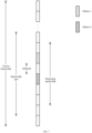
- FIG. 1 is a schematic diagram of frequency band division according to an embodiment of the present invention.
- a carrier bandwidth Carrier Bandwidth
- the carrier bandwidth further includes at least one bandwidth part (Bandwidth Part).
- Each bandwidth part includes at least one continuous subband, and each subband further includes a plurality of continuous subcarriers.
- Each bandwidth part may correspond to a group of system parameters (numerology), including, for example, but not limited to, a subcarrier spacing (Subcarrier spacing) and a cyclic prefix (Cyclic Prefix, CP).
- Different bandwidth parts may correspond to different system parameters.
- TTI Transmission Time Interval
- TTI Transmission Time Interval
- some or all subbands of a bandwidth part may be assigned to serve as a CSI reporting bandwidth (CSI reporting band), to report CSI corresponding to the CSI reporting bandwidth.
- CSI reporting bandwidth is briefly referred to as a reporting bandwidth below. It is not difficult to understand that the reporting bandwidth is a section of bandwidth, the CSI corresponding to the bandwidth needs to be reported, and the bandwidth includes a plurality of subbands.
- the reporting bandwidth carries a reference signal for performing channel measurement that is sent by a transmit end device, for example, but not limited to, a cell-specific reference signal (Cell-specific Reference Signal, CRS), a channel state information-reference signal (Channel State Information Reference Signal, CSI-RS), or a demodulation reference signal (Demodulation Reference Signal, DMRS).
- CRS Cell-specific Reference Signal
- CSI-RS Channel State Information Reference Signal
- DMRS demodulation Reference Signal
- a receive end device may measure the foregoing reference signals to obtain corresponding CSI.
- CSI of the entire reporting bandwidth that is, wideband CSI of the reporting bandwidth may be reported, or CSI of at least one subband in the reporting bandwidth may be reported.
- the reporting bandwidth includes a plurality of continuous subbands.
- subbands included in the reporting bandwidth may be discontinuous.
- the reporting bandwidth may include the subband 1, the subband 2, the subband 4, and the subband 6.
- a frequency band may alternatively be divided in another manner or by using levels.
- quantities of subcarriers included in subbands may be different.
- at least one level may be added or deleted between frequency band division levels shown in FIG. 1 .
- a specific frequency band division manner is not limited in this embodiment of the present invention.
- the receive end device obtains the channel state information based on the reference signal (Reference Signal, RS) transmitted by the transmit end device, and feeds back the obtained CSI to the transmit end device.
- the transmit end device may process a transmit signal based on the CSI, and sends the processed transmit signal to the receive end device.
- the CSI may further include, for example, but is not limited to, at least one of the following information: a channel quality indicator (Channel Quality Indicator, CQI), a precoding matrix indicator (Precoding Matrix Indicator, PMI), a CSI-RS resource indicator (CSI-RS Resource Indicator, CRI), and a rank indication (Rank Indication, RI).
- the transmit end device may perform processing by directly using CSI fed back by the receive end device; or the transmit end device may adjust the CSI fed back by the receive end device, and perform processing by using the adjusted CSI. For example, in a specific implementation process, the transmit end device may decrease an RI fed back by the receive end device, and perform processing by using the decreased RI. For another example, the transmit end device may further reconstruct a precoding matrix corresponding to a PMI fed back by the receive end device, and perform processing by using the reconstructed PMI.
- the reconstruction process may be, for example, but is not limited to, performing orthogonalization processing on precoding matrices corresponding to PMIs fed back by a plurality of simultaneously scheduled receive end devices.
- a method for transmitting data by simultaneously scheduling a plurality of receive end devices is also referred to as a multi-user multiple-input multiple-output (Multi-User Multiple-Input and Multiple-Output (MIMO), MU-MIMO) technology.
- MIMO Multiple-Input and Multiple-Output
- the transmit end device may further decrease a CQI fed back by the receive end device, and perform processing by using the decreased CQI. It should be noted that if the transmit end device adjusts the CSI fed back by the receive end device, the transmit end device may need to notify the receive end device of the adjusted CSI, so that the receive end device restores the transmit signal from a received signal based on the adjusted CSI.
- a base station adjusts an RI or a CQI
- the base station needs to notify the receive end device of the adjusted RI or the adjusted CQI.
- a specific manner of adjusting, by the transmit end device, the CSI fed back by the receive end device is not limited in this embodiment of the present invention.
- Embodiments of the present invention provide a technical solution, to help reduce the foregoing overheads.
- the technical solution provided in the embodiments of the present invention is described in detail with reference to the accompanying drawings and specific embodiments.
- FIG. 2 is an example of a schematic diagram of a wireless communications network 200 according to an embodiment of the present invention.
- the wireless communications network 200 includes base stations 202 to 206 and terminal devices 208 to 222.
- the base stations 202 to 206 may communicate with each other on backhaul (backhaul) links (as indicated by straight lines between the base stations 202 to 206).
- the backhaul link may be a wired backhaul link (for example, an optical fiber or a copper cable), or may be a wireless backhaul link (for example, microwave).
- the terminal devices 208 to 222 may communicate with the corresponding base stations 202 to 206 on radio links (as indicated by broken lines between the base stations 202 to 206 and the terminal devices 208 to 222).
- the base stations 202 to 206 are usually used as access devices to provide radio access services for the terminal devices 208 to 222 that are usually used as user equipment.
- each base station corresponds to a service coverage area (which may also be referred to as a cell, and is indicated by each oval area in FIG. 2 ).
- a terminal device entering the area may communicate with a base station by using a radio signal, to receive a radio access service provided by the base station.
- Service coverage areas of the base stations may overlap.
- a terminal device in an overlapping area may receive radio signals from a plurality of base stations. Therefore, these base stations may coordinate with each other, to provide a service for the terminal device.
- the plurality of base stations may provide the service for the terminal device in the overlapping area by using a coordinated multipoint (Coordinated multipoint, CoMP) technology.
- a coordinated multipoint Coordinatd multipoint, CoMP
- FIG. 2 service coverage areas of the base station 202 and the base station 204 overlap, and the terminal device 222 is in the overlapping area. Therefore, the terminal device 222 may receive radio signals from the base station 202 and the base station 204, and the base station 202 and the base station 204 may coordinate with each other, to provide a service for the terminal device 222.
- CoMP Coordinatd multipoint
- the terminal device 220 may receive radio signals from the base stations 202, 204, and 206, and the base stations 202, 204, and 206 may coordinate with each other, to provide a service for the terminal device 220.
- the base station may also be referred to as a NodeB (NodeB), an evolved NodeB (evolved NodeB, eNodeB), an access point (Access Point, AP), or the like.
- NodeB NodeB
- eNodeB evolved NodeB
- Access Point Access Point
- the base station may also be classified into a macro base station for providing a macro cell (Macro cell), a micro base station for providing a micro cell (Pico cell), a femto base station for providing a femto cell (Femto cell), and the like.
- a macro base station for providing a macro cell
- Micro cell a micro base station for providing a micro cell
- femto base station for providing a femto cell
- another name may also be used for a future base station.
- the terminal devices 208 to 222 may be various wireless communications devices having a wireless communication function, for example, but not limited to, a mobile cellular phone, a cordless phone, a personal digital assistant (Personal Digital Assistant, PDA), a smartphone, a notebook computer, a tablet computer, a wireless data card, a wireless modem (Modulator demodulator, Modem), or a wearable device such as a smartwatch.
- a wireless communication function for example, but not limited to, a mobile cellular phone, a cordless phone, a personal digital assistant (Personal Digital Assistant, PDA), a smartphone, a notebook computer, a tablet computer, a wireless data card, a wireless modem (Modulator demodulator, Modem), or a wearable device such as a smartwatch.
- IOT internet of things
- this type of device has the wireless communication function because of being configured with a wireless communications unit. Therefore, this type of device is also a type of wireless communications device.
- the terminal devices 208 to 222 may also be referred to as mobile consoles, mobile devices, mobile terminals, wireless terminals, handheld devices, clients, and the like.
- the base stations 202 to 206 and the terminal devices 208 to 222 may each be configured with a plurality of antennas, to support a MIMO (multiple-input multiple-output, Multiple Input Multiple Output) technology. Further, the base stations 202 to 206 and the terminal devices 208 to 222 may not only support a single-user MIMO (Single User MIMO, SU-MIMO) technology, but also support a multi-user MIMO (Multi-User MIMO, MU-MIMO) technology.
- the MU-MIMO may be implemented based on a space division multiple access (Space Division Multiple Access, SDMA) technology.
- the base stations 202 to 206 and the terminal devices 208 to 222 may further flexibly support a single-input single-output (Single Input Single Output, SISO) technology, a single-input multiple-output (Single Input Multiple Output, SIMO) technology, and a multiple-input single-output (Multiple Input Single Output, MISO) technology, to implement various types of diversity (for example, but not limited to, transmit diversity and receive diversity) and multiplexing technologies.
- SISO single Input Single Output
- SIMO single-input multiple-output
- MISO multiple-input single-output
- the diversity technology may include, for example, but is not limited to, a transmit diversity (Transmit Diversity, TD) technology and a receive diversity (Receive Diversity, RD) technology, and the multiplexing technology may be a spatial multiplexing (Spatial Multiplexing) technology.
- TD Transmit Diversity
- RD Receive Diversity
- the multiplexing technology may be a spatial multiplexing (Spatial Multiplexing) technology.
- the foregoing various types of technologies may further include a plurality of implementation solutions.
- the transmit diversity technology may include, for example, but is not limited to, diversity manners such as a space time transmit diversity (Space-Time Transmit Diversity, STTD), a space-frequency transmit diversity (Space-Frequency Transmit Diversity, SFTD), a time switched transmit diversity (Time Switched Transmit Diversity, TSTD), a frequency switched transmit diversity (Frequency Switch Transmit Diversity, FSTD), an orthogonal transmit diversity (Orthogonal Transmit Diversity, OTD), and a cyclic delay diversity (Cyclic Delay Diversity, CDD), and diversity manners obtained by deriving, evolving, and combining the foregoing various types of diversity manners.
- diversity manners such as a space time transmit diversity (Space-Time Transmit Diversity, STTD), a space-frequency transmit diversity (Space-Frequency Transmit Diversity, SFTD), a time switched transmit diversity (Time Switched Transmit Diversity, TSTD), a frequency switched transmit diversity (Frequency Switch Transmit Diversity, FSTD), an orthogonal transmit diversity
- transmit diversity manners such as space-time block coding (Space Time Block Coding, STBC), space frequency block coding (Space Frequency Block Coding, SFBC), and the CDD are used in an LTE (Long Term Evolution, Long Term Evolution) standard.
- space-time block coding Space Time Block Coding, STBC
- space frequency block coding Space Frequency Block Coding, SFBC
- LTE Long Term Evolution, Long Term Evolution
- the base stations 202 to 206 and the terminal devices 208 to 222 may communicate with each other by using various wireless communications technologies, for example, but not limited to, a time division multiple access (Time Division Multiple Access, TDMA) technology, a frequency division multiple access (Frequency Division Multiple Access, FDMA) technology, a code division multiple access (Code Division Multiple Access, CDMA) technology, a time division-synchronous code division multiple access (Time Division-Synchronous Code Division Multiple Access, TD-SCDMA) technology, an orthogonal frequency division multiple access (Orthogonal FDMA, OFDMA) technology, a single carrier frequency division multiple access (Single Carrier FDMA, SC-FDMA) technology, and a space division multiple access (Space Division Multiple Access, SDMA) technology, and evolved and derived technologies of these technologies.
- TDMA time division multiple access
- FDMA frequency division multiple access
- CDMA code division multiple access
- CDMA code division multiple access
- TD-SCDMA time division-synchronous code division multiple access
- radio Access Technology As a radio access technology (Radio Access Technology, RAT), the foregoing wireless communications technology is adopted in various wireless communication standards, so that various wireless communications systems (or networks) and evolved systems of these wireless communications systems well known today are constructed. These wireless communications systems include but are not limited to a global system for mobile communications (Global System for Mobile Communications, GSM), CDMA 2000, wideband CDMA (Wideband CDMA, WCDMA), Wi-Fi defined in a 802.22 series standard, worldwide interoperability for microwave access (Worldwide Interoperability for Microwave Access, WiMAX), long term evolution (Long Term Evolution, LTE), and LTE-advanced (LTE-Advanced, LTE-A). Unless otherwise specified, the technical solutions provided in the embodiments of the present invention may be applied to the foregoing various wireless communications technologies and wireless communications systems. In addition, the terms “system” and “network” may be interchanged with each other.
- GSM Global System for Mobile Communications
- WCDMA wideband CDMA
- Wi-Fi defined in
- the wireless communications network 200 shown in FIG. 2 is merely used as an example, and is not intended to limit the technical solutions of the present invention.
- the wireless communications network 200 may further include another device, and a quantity of base stations and a quantity of terminal devices may be further configured based on a specific requirement.
- access devices such as the base stations 202 to 206 shown in FIG. 2 may be used as transmit end devices, and user equipment such as the terminal devices 208 to 222 shown in FIG. 2 may be used as receive end devices.
- FIG. 3 is an example of a schematic diagram of a logical structure of a communications device 300 according to an embodiment of the present invention.
- the communications device 300 may not only be configured to implement a receive end device, but also be configured to implement a transmit end device.
- the communications device 300 includes a processing module 302 and a transceiver module 304. Specific functions of these modules are described in detail below.
- the processing module 304 may be implemented by using a processor 402 in a communications device 400 to be described below, or may be implemented by using a processor 402 and a memory 408 in the communications device 400.
- the transceiver module 304 may be implemented by using a transceiver 404 in the communications device 400.
- another implementation may alternatively be used.
- FIG. 4 is an example of a schematic diagram of a hardware structure of a communications device 400 according to an embodiment of the present invention.
- the communications device 400 may not only be configured to implement a receive end device, but also be configured to implement a transmit end device.
- the communications device 400 includes a processor 402, a transceiver 404, a plurality of antennas 406, a memory 408, an I/O (input/output, Input/Output) interface 410, and a bus 412.
- the memory 408 is further configured to store an instruction 4082 and data 4084.
- the processor 402, the transceiver 404, the memory 408, and the I/O interface 410 are in communication connection with each other by using the bus 412.
- the plurality of antennas 406 are connected to the transceiver 404.
- the processor 402, the transceiver 404, the memory 408, and the I/O interface 410 may alternatively be in communication connection with each other in another connection manner in addition to using the bus 412.
- the processor 402 may be a general-purpose processor.
- the general-purpose processor may be a processor that performs a particular step and/or operation by reading and executing an instruction (such as the instruction 4082) stored in a memory (such as the memory 408). In a process in which the general-purpose processor performs the foregoing step and/or operation, data (such as the data 4084) stored in the memory (such as the memory 408) may be used.
- the general-purpose processor may be, for example, but is not limited to, a central processing unit (Central Processing Unit, CPU).
- the processor 402 may alternatively be a special-purpose processor.
- the special-purpose processor may be a processor specially designed to perform a particular step and/or operation.
- the special-purpose processor may be, for example, but is not limited to, a digit signal processor (Digital Signal Processor, DSP), an application-specific integrated circuit (Application Specific Integrated Circuit, ASIC), or a field programmable gate array (Field Programmable Gate Array, FPGA).
- DSP Digital Signal Processor
- ASIC Application Specific Integrated Circuit
- FPGA Field Programmable Gate Array
- the processor 402 may alternatively be a combination of a plurality of processors, for example, a multicore processor.
- the transceiver 404 is configured to receive and send a signal.
- a specific process of signal receiving and sending is performed by using at least one of the plurality of antennas 406.
- the memory 408 may be various types of storage media, for example, a random access memory (Random Access Memory, RAM), a read-only memory (Read-Only Memory, ROM), a non-volatile RAM (Non-Volatile RAM, NVRAM), a programmable ROM (Programmable ROM, PROM), an erasable PROM (Erasable PROM, EPROM), an electrically erasable PROM (Electrically Erasable PROM, EEPROM), a flash memory, an optical memory, and a register.
- the memory 408 is specifically configured to store the instruction 4082 and the data 4084.
- the processor 402 may perform a particular step and/or operation by reading and executing the instruction 4082 stored in the memory 408. In a process of performing the foregoing step and/or operation, the data 4084 may need to be used.
- the I/O interface 410 is configured to receive an instruction and/or data from a peripheral device, and output an instruction and/or data to the peripheral device.
- the processor may be configured to perform, for example, but not limited to, baseband related processing
- the transceiver may be configured to perform, for example, but not limited to, radio frequency transmission and receiving.
- the foregoing components may be separately disposed on chips independent of each other, or at least some or all of the components may be disposed on a same chip.
- the processor may further be classified into an analog baseband processor and a digital baseband processor.
- the analog baseband processor and the transceiver may be integrated on a same chip, and the digital baseband processor may be disposed on an independent chip. With continuous development of integrated circuit technologies, more components can be integrated on a same chip.
- the digital baseband processor and a plurality of application processors may be integrated on a same chip.
- a chip may be referred to as a system on chip (System on Chip).
- System on Chip system on Chip
- the communications device 400 may further include other hardware components, and the other hardware components are not listed in this specification one by one.
- FIG. 5 is an example of a flowchart of a channel measurement method 500 according to an embodiment of the present invention.
- the method 500 may be performed by a receive end device.
- the receive end device may be implemented by using the communications device 300 shown in FIG. 3 and the communications device 400 shown in FIG. 4 .
- Step 502. Obtain, for a to-be-measured frequency band including at least one reporting subband and at least one missing subband, channel state information of each reporting subband and channel state information of each missing subband, where the channel state information of each reporting subband is obtained based on channel estimation, and the channel state information of each missing subband is obtained according to a reference rule with reference to channel state information of a reporting subband that is indicated by the reference rule and that is in the at least one reporting subband.
- step 502 may be performed by the processing module 302 and the processor 402.
- Step 504. Send a measurement report of the to-be-measured frequency band to a transmit end device, where the measurement report includes the channel state information of each reporting subband in the at least one reporting subband, so that the transmit end device obtains, for each missing subband, channel state information of the missing subband according to the reference rule with reference to the channel state information of the reporting subband that is indicated by the reference rule and that is in the at least one reporting subband.
- step 504 may be performed by the transceiver module 304 and the transceiver 404.
- the measurement report including channel state information of only some subbands is fed back in this embodiment of the present invention, thereby helping reduce feedback overheads brought by channel measurement.
- the receive end device and the transmit end device generate channel state information of each subband in the other subbands based on a same rule and according to channel state information of a subband indicated by the rule in the some subbands, thereby helping implement consistency of the channel state information between the receive end device and the transmit end device, and avoiding adverse impact on a transmission effect.
- a to-be-measured frequency band may include a plurality of subbands, and these subbands may be continuous, may be discontinuous, or may be partially continuous. Whether these subbands are continuous and continuous forms of these subbands are not limited in this embodiment of the present invention.
- the to-be-measured frequency band may be the reporting bandwidth described above.
- the plurality of subbands included in the to-be-measured frequency band may be classified into two types of subbands: a reporting subband and a missing subband respectively.
- each of the types of subbands includes at least one subband.
- channel state information of a reporting subband is obtained based on channel estimation, and channel state information of a missing subband is obtained according to a reference rule with reference to channel state information of a reporting subband that is indicated by the reference rule and that is in reporting subbands.
- the channel state information of the reporting subband is included in a measurement report and sent to the transmit end device, and the channel state information of the missing subband is not sent to the transmit end device.
- the transmit end device also needs to obtain the channel state information of the missing subband according to the reference rule with reference to the channel state information of the reporting subband that is indicated by the reference rule and that is in the reporting subbands. In this way, the channel state information, of the missing subband, obtained by the receive end device is the same as that obtained by the transmit end device.
- the to-be-measured frequency band provided in this embodiment of the present invention may be understood with reference to FIG. 6 and FIG. 7 .
- the to-be-measured frequency band is specifically reflected as a reporting bandwidth.
- a reporting bandwidth includes six subbands, which are respectively six subbands that the reporting bandwidth spans across. In these subbands, three subbands indicated by a pattern 1 are missing subbands, and the other three subbands are reporting subbands.
- a reporting bandwidth spans across six subbands, but a subband indicated by a pattern 2 is not a part of the reporting bandwidth. Therefore, the reporting bandwidth includes only five subbands other than the subband indicated by the pattern 2 in the six subbands that are spanned across.
- one subband indicated by a pattern 1 is a missing subband, and the other four subbands are reporting subbands.
- the channel state information of the missing subband needs to be obtained with reference to the channel state information of the reporting subband
- the channel state information of the missing subband and the channel state information of the reporting subband should belong to a same type, and this type of channel state information may be, for example, but is not limited to, one of a CQI, a PMI, an RI, and a CRI.
- the receive end device may feed back, to the transmit end device, a plurality of types of channel state information of a subband included in the to-be-measured frequency band. Each type of channel state information may be reported with reference to the method 500.
- a measurement report or another message may include an indication for the missing subband.
- there are a plurality of types of manners of the foregoing indication for example, but not limited to, an implicit indication, an explicit indication, a direct indication, an indirect indication, a combination of the foregoing indication manners, or the like.
- the direct indication means directly indicating to-be-indicated information, for example, directly indicating a missing subband.
- the indirect indication means indicating to-be-indicated information by indicating other information, for example, indicating a missing subband by indicating a reporting subband.
- the foregoing indication refer to the prior art. This is not limited in the present invention. It should be noted that the foregoing descriptions of the manners of the indication are also applicable to another indication mentioned in this specification.
- the missing subband may be specified by the transmit end device and indicated to the receive end device.
- the method 500 may further include:
- the foregoing step of receiving missing subband indication information from the transmit end device may be performed by the transceiver module 304 and the transceiver 404, and the foregoing step of determining the at least one missing subband based on the missing subband indication information may be performed by the processing module 302 and the processor 402. It should be noted that the foregoing missing subband indication process may be used as a part of the method 500, or the method 500 may be used as a part of the foregoing process.
- the missing subband indication information may be sent by using one of the following signaling:
- missing subband needs to be frequently or dynamically indicated, physical layer signaling may be preferentially used to transmit the missing subband indication information.
- the physical layer signaling is also referred to as layer 1 (Layer 1, L1) signaling, and may usually be carried in a control part in a physical layer frame.
- a typical example of the L1 signaling is downlink control information (Downlink Control Information, DCI) carried on a physical downlink control channel (Physical Downlink Control Channel, PDCCH) defined in an LTE standard.
- DCI Downlink Control Information
- PDCCH Physical Downlink Control Channel
- the L1 signaling may alternatively be carried in a data part in the physical layer frame. It is not difficult to learn that a sending period or a signaling period of the L1 signaling is usually a period of the physical layer frame. Therefore, this type of signaling is usually used to implement some dynamic control, to transfer some information that change frequently. For example, resource allocation information may be transmitted by using the physical layer signaling.
- the media access control (Media Access Control, MAC) layer signaling is layer 2 (Layer 2) signaling, and may be usually carried in, for example, but not limited to, a frame header of a layer 2 frame.
- the frame header may further carry, for example, but not limited to, information such as a source address and a destination address.
- the layer 2 frame usually further includes a frame body in addition to the frame header.
- the L2 signaling may alternatively be carried in the frame body of the layer 2 frame.
- a typical example of the layer 2 signaling is signaling carried in a frame control (Frame Control) field in a frame header of a MAC frame in the 802.11 series standards, or a MAC control entity (Control Entity, MAC-CE) defined in some protocols.
- the layer 2 frame may be carried in the data part of the physical layer frame.
- the missing subband indication information may alternatively be sent by using other layer 2 signaling than the media access control layer signaling.
- the radio resource control (Radio Resource Control, RRC) signaling is layer 3 (Layer 3) signaling, and is usually some control messages.
- the L3 signaling may be usually carried in the frame body of the layer 2 frame.
- a sending period or a control period of the L3 signaling is usually relatively long, and the L3 signaling is applicable to sending of some information that does not change frequently.
- the L3 signaling is usually used to carry some configuration information.
- the missing subband indication information may alternatively be sent by using other layer 3 signaling than the RRC signaling.
- the missing subband indication information is used to indicate the at least one missing subband, may be specifically used to indicate the at least one missing subband one by one, or may be used to indicate a missing subband configuration solution, where the configuration solution records the at least one missing subband. It is not difficult to understand that in the former solution, an indication manner is more flexible but indication overheads are relatively high, and in the latter solution, indication overheads are relatively low but an indication manner is relatively fixed.
- missing subband configuration solution When the missing subband configuration solution is used, a plurality of missing subband configuration solutions may be agreed on in a communication standard, and these missing subband configuration solutions may be written in advance before delivery of the receive end device and the transmit end device, so that in a process of interaction between the receive end device and the transmit end device, an index of a missing subband configuration solution is transferred to indicate missing subbands.
- the foregoing plurality of missing subband configuration solutions may be configured by the transmit end device for the receive end device in a process (for example, an initial access process) of interaction between the transmit end device and the receive end device.
- the method 500 may further include:
- the foregoing step of receiving missing subband configuration information from the transmit end device may be performed by the transceiver module 304 and the transceiver 404, and the foregoing step of determining the plurality of missing subband configuration solutions based on the missing subband configuration information may be performed by the processing module 302 and the processor 402. It should be noted that the foregoing missing subband configuration process may be used as a part of the method 500, or the method 500 may be used as a part of the foregoing process.
- the missing subband configuration information may be sent by using one of the following signaling:
- a sending period of the missing subband configuration information is relatively long, and therefore, the media access control layer signaling or the radio resource control signaling may be preferably used to transmit the missing subband configuration information.
- the missing subband may alternatively be specified in a communication standard in advance. It is not difficult to understand that compared with the manner of indicating the missing subband, the manner of specifying the missing subband in the communication standard in advance is beneficial to reducing signaling overheads brought by the indication.
- the foregoing measurement report may be transmitted by using one message, or may be transmitted by using a plurality of messages.
- a specific transmission manner is not limited in this embodiment of the present invention.
- a plurality of types of same-type information (such as the channel state information) may be included in a measurement report and independent of each other, or may be included in a measurement report in a mutual association manner, or may be included in a measurement report in another manner.
- the foregoing mutual association manner may be a differential manner.
- a specific inclusion manner is not limited in the embodiments of the present invention. It should be noted that the foregoing descriptions are also applicable to other signaling in the embodiments of the present invention, for example, but not limited to, the missing subband indication information.
- the reference rule specifies the following sub-rules:
- the sub-rule A may be designed based on a specific requirement, and specific content of the sub-rule A is not limited in the embodiments of the present invention.
- the sub-rule A may be, for example, but is not limited to, one or any combination of the following rules:
- the following sub-rule may be obtained by combining the foregoing manner 2 with the foregoing manner 5: a reporting subband that is continuous with the missing subband and whose frequency is lower than that of the missing subband.
- a plurality of sub-rules may be obtained through combination, and a relationship between the sub-rules is further set, to avoid a case in which a reporting subband complying with the sub-rule A does not exist.
- a sub-rule X and a sub-rule Y are obtained through combination, and it is further stipulated that when the reporting subband cannot be determined through the sub-rule X, the reporting subband is determined through the sub-rule Y.
- reporting subbands determined according to the sub-rule A.
- the sub-rule B may be designed based on a specific requirement, and specific content of the sub-rule B is not limited in the embodiments of the present invention.
- the sub-rule B may be that if one reporting subband is determined according to the sub-rule A, channel state information of the reporting subband is set as channel state information of the missing subband; or channel state information of the missing subband is calculated based on the channel state information of the reporting subband.
- the sub-rule B may be that if a plurality of reporting subbands are determined according to the sub-rule A, an average value of channel state information of these reporting subbands is set as channel state information of the missing subband, or for each missing subband, based on channel state information of one or more reporting subbands whose frequency is higher than that of the missing subband (for example, a reporting subband closest to the missing subband), and/or one or more reporting subbands whose frequency is lower than that of the missing subband (for example, a reporting subband closest to the missing subband), channel state information of the missing subband is obtained through interpolation, or channel state information of the missing subband is calculated in another manner based on channel state information of a plurality of reporting subbands.
- a plurality of calculation methods may be used when channel state information of the missing subband is calculated.
- a specifically used calculation method is not limited in the embodiments of the present invention.
- the receive end device may also obtain channel state information of the missing subband through channel estimation, but still does not send the channel state information to the transmit end device.
- the transmit end device may set channel state information of the missing subband without depending on the reference rule. In other words, when setting the channel state information of the missing subband, the transmit end device may not consider an actual channel environment. It is not difficult to understand that although this design solution can reduce feedback overheads brought by channel measurement, consistency of the channel state information of the missing subband cannot be implemented between the receive end device and the transmit end device, probably resulting in bringing adverse impact on a transmission effect.
- a measurement report or another message may include an indication for the reference rule.
- the reference rule may alternatively be indicated by the transmit end device.
- the method 500 may further include:
- reference rule indication process may be used as a part of the method 500, or the method 500 may be used as a part of the foregoing process.
- the reference rule indication information may be sent by using one of the following signaling:
- the foregoing step of receiving reference rule indication information from the transmit end device may be performed by the transceiver module 304 and the transceiver 404, and the foregoing step of determining the reference rule based on the reference rule indication information may be performed by the processing module 302 and the processor 402.
- a plurality of reference rules may be agreed on in a communication standard, and these reference rules are written in advance before delivery of the receive end device and the transmit end device, so that in a process of interaction between the receive end device and the transmit end device, the reference rule is indicated by using reference rule indication information carrying, for example, a reference rule index.
- the plurality of reference rules may be configured by the transmit end device for the receive end device in a process (for example, an initial access process) of interaction between the transmit end device and the receive end device.
- the method 500 may further include:
- the foregoing step of receiving reference rule configuration information from the transmit end device may be performed by the transceiver module 304 and the transceiver 404, and the foregoing step of determining the plurality of reference rule based on the reference rule configuration information may be performed by the processing module 302 and the processor 402. It should be noted that the foregoing reference rule configuration process may be used as a part of the method 500, or the method 500 may be used as a part of the foregoing process.
- the reference rule configuration information may be sent by using one of the following signaling:
- a sending period of the reference rule configuration information is relatively long, and therefore, the media access control layer signaling or the radio resource control signaling may be preferably used to transmit the reference rule configuration information.
- the reference rule may alternatively be specified in a communication standard in advance. It is not difficult to understand that compared with the manner of indicating the reference rule, the manner of specifying the reference rule in the communication standard in advance is beneficial to reducing signaling overheads brought by the indication, and is applicable to a case in which the reference rule is not frequently changed.
- the method 500 may further include:
- the step of calculating channel-related information based on a channel state information group may be performed by the processing module 302 and the processor 402, and the step of sending the channel-related information to the transmit end device may be performed by the transceiver module 304 and the transceiver 404.
- the channel state information group may include the channel state information of the missing subband, or may include the channel state information of the reporting subband, or a combination of these pieces of channel state information.
- the foregoing other information is not limited in the embodiments of the present invention.
- the channel-related information may be wideband channel state information, subband channel state information, or other information.
- the channel-related information may be channel state information of the to-be-measured frequency band, that is, wideband channel state information of the to-be-measured frequency band.
- the calculating channel-related information based on a channel state information group may be specifically: calculating the channel state information of the to-be-measured frequency band based on channel state information of reporting subbands and channel state information of missing subbands.
- the channel state information of the to-be-measured frequency band may be a CQI
- the channel state information of the reporting subbands and the channel state information of the missing subbands may each be a PMI
- the channel state information of the reporting subbands and the channel state information of the missing subbands may each alternatively be a CQI.
- a person skilled in the art should understand that in addition to calculating the channel state information of the to-be-measured frequency band based on the channel state information of the reporting subbands and the channel state information of the missing subbands, another method may also be used to calculate the channel state information of the to-be-measured frequency band, which is, for example, but is not limited to, using the to-be-measured frequency band as a whole to calculate the channel state information of the to-be-measured frequency band. Content related to this belongs to the prior art, and is not repeatedly described in the embodiments of the present invention.
- the channel-related information is the channel state information of the to-be-measured frequency band, and types of the channel state information, the channel state information of the reporting subbands, and the channel state information of the missing subbands are the same
- the channel state information of the to-be-measured frequency band and channel state information of each reporting subband may be reported in a differential manner. Specifically, the channel state information of the to-be-measured frequency band, and a difference between the channel state information of each reporting subband and the channel state information of the to-be-measured frequency band may be reported.
- the channel-related information may alternatively be other channel state information of the missing subband.
- the calculating channel-related information based on a channel state information group may be specifically: calculating, based on the channel state information of the missing subband, other channel state information of the missing subband, where a type of the channel state information is different from that of the foregoing other channel state information.
- the channel state information may be a PMI
- the other channel state information may be a CQI.
- the channel-related information may be other information of the missing subband.
- the calculating channel-related information based on a channel state information group may be specifically: calculating, based on channel state information of a missing subband, other information of the missing subband.
- the other information may be, for example, but is not limited to, a signal to interference plus noise ratio (Signal to Interference plus Noise Ratio, SINR) of the missing subband.
- specific content about the channel-related information is not limited in the embodiments of the present invention.
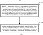
- FIG. 8 is an example of a flowchart of a channel measurement method 800 according to an embodiment of the present invention.
- the method 800 may be performed by a transmit end device.
- the transmit end device may be implemented by using the communications device 300 shown in FIG. 3 and the communications device 400 shown in FIG. 4 .
- Step 802. Receive a measurement report of a to-be-measured frequency band from a receive end device, where the to-be-measured frequency band includes at least one reporting subband and at least one missing subband, the measurement report includes channel state information of each reporting subband in the at least one reporting subband, and the channel state information of each reporting subband is obtained by the receive end device based on channel estimation.
- step 802 may be performed by the transceiver module 304 and the transceiver 404.
- Step 804. Obtain, for each missing subband, channel state information of the missing subband according to a reference rule with reference to channel state information of a reporting subband that is indicated by the reference rule and that is in the at least one reporting subband.
- step 804 may be performed by the processing module 302 and the processor 402.
- the method 800 may further include:
- the step of generating missing subband indication information may be performed by the processing module 302 and the processor 402, and the step of sending the missing subband indication information to the receive end device may be performed by the transceiver module 304 and the transceiver 404. It should be noted that the foregoing missing subband indication process may be used as a part of the method 800, or the method 800 may be used as a part of the foregoing process.
- the method 800 may further include:
- the step of generating missing subband configuration information may be performed by the processing module 302 and the processor 402, and the step of sending the missing subband configuration information to the receive end device may be performed by the transceiver module 304 and the transceiver 404. It should be noted that the foregoing missing subband configuration process may be used as a part of the method 800, or the method 800 may be used as a part of the foregoing process.
- the method 800 may further include:
- the step of generating reference rule indication information may be performed by the processing module 302 and the processor 402, and the step of sending the reference rule indication information to the receive end device may be performed by the transceiver module 304 and the transceiver 404. It should be noted that the foregoing reference rule indication process may be used as a part of the method 800, or the method 800 may be used as a part of the foregoing process.
- the method 800 may further include:
- the step of generating reference rule configuration information may be performed by the processing module 302 and the processor 402, and the sending the reference rule configuration information to the receive end device may be performed by the transceiver module 304 and the transceiver 404.
- the foregoing reference rule configuration process may be used as a part of the method 800, or the method 800 may be used as a part of the foregoing process.
- the method 800 may further include: receiving channel-related information from the receive end device, where the channel-related information is obtained by the receive end device through calculation based on a channel state information group, and the channel state information group includes channel state information of at least one missing subband in the at least one missing subband.
- the step may be performed by the transceiver module 304 and the transceiver 404.
- the method 800 corresponds to the method 500, and related technical content is described in detail above with reference to the method 500. Therefore, details are not described herein again.
- an embodiment of the present invention further provides a method for reporting uplink control information (Uplink Control Information, UCI).
- UCI Uplink Control Information
- FIG. 9 is an example of a flowchart of an uplink control information sending method 900 according to an embodiment of the present invention.
- the method 900 may be performed by a receive end device.
- the receive end device may be implemented by using the communications device 300 shown in FIG. 3 and the communications device 400 shown in FIG. 4 .
- Step 902. Generate uplink control information, where the uplink control information includes a first part and a second part, and the first part and the second part are independently encoded; a quantity of information bits corresponding to the first part is fixed, and the first part includes information for indicating a quantity of information bits corresponding to the second part; and the second part includes channel state information of M subbands of a to-be-measured frequency band, and the to-be-measured frequency band includes N subbands, where 1 ⁇ M ⁇ N.
- Step 904. Send the uplink control information to a transmit end device.
- step 902 may be performed by the processing module 302 and the processor 402, and step 904 may be performed by the transceiver module 304 and the transceiver 404.
- UCI usually includes a scheduling request, channel state information, and information related to retransmission control (for example, an ACK and a NACK).
- ACK and a NACK information related to retransmission control
- Transmission processing such as encoding and modulation needs to be performed before the UCI is transmitted, so that the UCI is converted into a modulation symbol form from a bit form for transmission.
- the information refers to an information bit that is included in the UCI and on which transmission processing such as encoding and modulation has not been performed, that is, an original information bit or an information bit payload.
- a quantity of information bits of an ACK or a NACK included in UCI may be 1 or 2, respectively corresponding to a case in which there is one codeword (Codeword) and a case in which there are two codewords.
- the uplink control information may include two parts: the first part and the second part respectively, and the first part and the second part are separately independently encoded. Still further, a quantity of information bits included in the first part is fixed, and the first part includes information for indicating a quantity of information bits included in the second part.
- the second part further includes the channel state information of the M subbands of the to-be-measured frequency band, and the measurement frequency band includes N subbands, where 1 ⁇ M ⁇ N.
- the first part may further include channel state information of the to-be-measured frequency band, that is, wideband channel state information.
- a type of subband channel state information may be the same as or different from a type of the wideband channel state information. Still further, both of the two may be one of a CQI, a PMI, an RI, and a CRI.
- the channel state information of the M subbands should be understood as belonging to a same type.
- the channel state information of the to-be-measured frequency band may be included in the first part, and the channel state information of the subbands of the to-be-measured frequency band may be included in the second part.
- this embodiment of the present invention provides a method for transmitting channel state information of a subband of a to-be-measured frequency band.
- the receive end device may feed back, to the transmit end device, a plurality of types of channel state information of a subband included in the to-be-measured frequency band.
- the receive end device may feed back a plurality of types of channel state information of the to-be-measured frequency band to the transmit end device.
- the method 900 for reporting For each type of channel state information, refer to the method 900 for reporting. It is not difficult to understand that the measurement report of the to-be-measured frequency band described above can be included in the uplink control information.
- FIG. 10 is an example of a flowchart of an uplink control information receiving method 1000 according to an embodiment of the present invention.
- the method 900 may be performed by a transmit end device.
- the transmit end device may be implemented by using the communications device 300 shown in FIG. 3 and the communications device 400 shown in FIG. 4 .
- Step 1002 Receive uplink control information, where the uplink control information includes a first part and a second part, and the first part and the second part are independently encoded; a quantity of information bits corresponding to the first part is fixed, and the first part includes information for indicating a quantity of information bits corresponding to the second part; and the second part includes channel state information of M subbands of a to-be-measured frequency band, and the to-be-measured frequency band includes N subbands, where 1 ⁇ M ⁇ N.
- Step 1004. Determine the channel state information of the M subbands of the to-be-measured frequency band based on the uplink control information.
- channel state information of the missing subband may be further determined based on the technical solution described above.
- step 1002 may be performed by the transceiver module 304 and the transceiver 404, and step 1004 may be performed by the processing module 302 and the processor 402.
- the method 1000 corresponds to the method 900, and related technical content is described in detail above with reference to the method 900. Therefore, details are not described herein again.
- All or some of the foregoing embodiments may be implemented by using software, hardware, firmware, or any combination thereof.
- the embodiments may be implemented completely or partially in a form of a computer program product.
- the computer program product includes one or more computer instructions.
- the computer program instructions When the computer program instructions are loaded and executed on a computer, the procedure or functions according to the embodiments of the present invention are all or partially generated.
- the computer may be a general-purpose computer, a special-purpose computer, a computer network, or other programmable apparatuses.
- the computer instructions may be stored in a computer-readable storage medium or may be transmitted from a computer-readable storage medium to another computer-readable storage medium.
- the computer instructions may be transmitted from a website, computer, server, or data center to another website, computer, server, or data center in a wired (for example, a coaxial cable, an optical fiber, or a digital subscriber line (DSL)) or wireless (for example, infrared, radio, or microwave) manner.
- the computer-readable storage medium may be any usable medium accessible by a computer, or a data storage device, such as a server or a data center, integrating one or more usable media.
- the usable medium may be a magnetic medium (for example, a floppy disk, a hard disk, or a magnetic tape), an optical medium (for example, a DVD), a semiconductor medium (for example, a solid-state drive Solid State Disk (SSD)), or the like.
- a magnetic medium for example, a floppy disk, a hard disk, or a magnetic tape
- an optical medium for example, a DVD
- a semiconductor medium for example, a solid-state drive Solid State Disk (SSD)
Description
- Embodiments of the present invention relate to channel measurement technologies, and in particular, to a channel measurement method.
- Obtaining channel state information (Channel State Information, CSI) through channel measurement is crucial to improving transmission quality of wireless communication. During channel measurement, a receive end device (for example, user equipment such as a smartphone) obtains channel state information based on a reference signal (Reference Signal, RS) transmitted by a transmit end device (for example, an access device such as a base station), and feeds back obtained CSI to the transmit end device. The transmit end device processes a transmit signal based on the CSI and sends the processed transmit signal to the receive end device. It can be learned that CSI-based wireless transmission is more compatible with a channel environment. Therefore, transmission quality is better.
- Usually, the CSI may be sent from the receive end device to the transmit end device on a physical uplink shared channel (Physical Uplink Shared Channel, PUSCH). The CSI transmitted on the PUSCH may include wideband (Wideband) CSI, or may include a plurality of pieces of subband (Subband) CSI, or may include both wideband CSI and a plurality of pieces of subband CSI. The wideband CSI may be understood as CSI obtained through calculation based on a wideband, and the subband CSI may be understood as CSI obtained through calculation based on a subband. The wideband described herein may be, for example, but is not limited to, an entire system bandwidth, or a bandwidth corresponding to one radio frequency carrier, or may be an entire block of bandwidth. The entire block of bandwidth includes a plurality of subbands, and an example of the entire block of bandwidth may be a to-be-measured bandwidth to be described below. A wideband may be divided into a plurality of subbands, and a width of the subband may be set based on, for example, but not limited to, a specific system design requirement. When there is a relatively large amount of subband CSI that needs to be fed back, very high overheads are caused.
- Therefore, a technical solution is required, to reduce feedback overheads of the subband CSI.
- The present invention is defined by the independent claims. Further developments are shown by the dependent claims.
- In view of this, it is indeed necessary to provide a channel measurement solution, to reduce feedback overheads of subband CSI.
- The embodiments of
figures 5 and8 fall under the scope of the claims. All the other embodiments do not fall under the scope of the claims. They are nonetheless retained as examples useful to better understand the invention. - Compared with feeding back a measurement report that includes channel state information of each subband, the measurement report including channel state information of only some subbands is fed back in this embodiment of the present invention, thereby helping reduce feedback overheads brought by channel measurement. In addition, for channel state information of other subbands, the receive end device and the transmit end device generate channel state information of each subband in the other subbands based on a same rule and according to channel state information of a subband indicated by the rule in the some subbands, thereby helping implement consistency of the channel state information between the receive end device and the transmit end device, and avoiding adverse impact on a transmission effect.
-
-
FIG. 1 is a schematic diagram of frequency band division according to an embodiment of the present invention; -
FIG. 2 is an example of a schematic diagram of a wireless communications network according to an embodiment of the present invention; -
FIG. 3 is an example of a schematic diagram of a logical structure of a communications device according to an embodiment of the present invention; -
FIG. 4 is an example of a schematic diagram of a hardware structure of a communications device according to an embodiment of the present invention; -
FIG. 5 is an example of a flowchart of achannel measurement method 500 according to an embodiment of the present invention; -
FIG. 6 is a schematic diagram of frequency band division according to another embodiment of the present invention; -
FIG. 7 is a schematic diagram of frequency band division according to still another embodiment of the present invention; -
FIG. 8 is an example of a flowchart of a channel measurement method according to an embodiment of the present invention; -
FIG. 9 is an example of a flowchart of an uplink control information sending method according to an embodiment of the present invention; and -
FIG. 10 is an example of a flowchart of an uplink control information receiving method according to an embodiment of the present invention. - A next generation wireless communications system being developed currently may also be referred to as a new radio (New Radio, NR) system or a 5G system. A latest research progress of a next generation wireless communication standard indicates that CSI may be sent from a receive end device to a transmit end device on a physical uplink shared channel (Physical Uplink Shared Channel, PUSCH). A person skilled in the art should understand that compared with a physical uplink control channel (Physical Uplink Control Channel, PUCCH) mainly used to transmit control information, the PUSCH is mainly used to transmit data. Therefore, during CSI transmission, the PUSCH may further transmit data or may not transmit data. For example, a PUSCH in an uplink subframe (Subframe) may transmit both CSI and data, or may transmit only CSI but not transmit data. The CSI is usually included in uplink control information (Uplink Control Information, UCI), and the UCI is transmitted on the PUSCH. The UCI may further include at least two parts. A quantity of information bits included in a first part is fixed, and the first part is used to indicate a quantity of information bits in a second part. In addition, a priority of the first part is higher than that of the second part. Still further, the first part and the second part may be separately independently encoded. A person skilled in the art should understand that a finally determined next generation wireless communication standard may further be changed. Therefore, the finally determined next generation wireless communication standard may be different from that in the foregoing latest research progress.
-
FIG. 1 is a schematic diagram of frequency band division according to an embodiment of the present invention. As shown inFIG. 1 , a carrier bandwidth (Carrier Bandwidth) may be considered as a wideband, and the carrier bandwidth further includes at least one bandwidth part (Bandwidth Part). Each bandwidth part includes at least one continuous subband, and each subband further includes a plurality of continuous subcarriers. - Each bandwidth part may correspond to a group of system parameters (numerology), including, for example, but not limited to, a subcarrier spacing (Subcarrier spacing) and a cyclic prefix (Cyclic Prefix, CP). Different bandwidth parts may correspond to different system parameters. Optionally, in a same transmission time interval (Transmission Time Interval, TTI), in a plurality of bandwidth parts, only one bandwidth part may be available and other bandwidth parts are unavailable.
- During CSI reporting, some or all subbands of a bandwidth part may be assigned to serve as a CSI reporting bandwidth (CSI reporting band), to report CSI corresponding to the CSI reporting bandwidth. For ease of description, the CSI reporting bandwidth is briefly referred to as a reporting bandwidth below. It is not difficult to understand that the reporting bandwidth is a section of bandwidth, the CSI corresponding to the bandwidth needs to be reported, and the bandwidth includes a plurality of subbands. The reporting bandwidth carries a reference signal for performing channel measurement that is sent by a transmit end device, for example, but not limited to, a cell-specific reference signal (Cell-specific Reference Signal, CRS), a channel state information-reference signal (Channel State Information Reference Signal, CSI-RS), or a demodulation reference signal (Demodulation Reference Signal, DMRS). The foregoing technical content related to the reference signals belongs to the prior art, and is not limited in this embodiment of this application. A receive end device may measure the foregoing reference signals to obtain corresponding CSI. During CSI reporting, CSI of the entire reporting bandwidth, that is, wideband CSI of the reporting bandwidth may be reported, or CSI of at least one subband in the reporting bandwidth may be reported. The foregoing two reporting manners may be further combined and used, or another reporting manner is used. As shown in
FIG. 1 , the reporting bandwidth includes a plurality of continuous subbands. However, in a specific implementation process, subbands included in the reporting bandwidth may be discontinuous. For example, for six continuous subbands in a bandwidth part: asubband 1 to a subband 6, the reporting bandwidth may include thesubband 1, thesubband 2, the subband 4, and the subband 6. In a specific implementation process, a frequency band may alternatively be divided in another manner or by using levels. For example, in different division manners, quantities of subcarriers included in subbands may be different. For another example, at least one level may be added or deleted between frequency band division levels shown inFIG. 1 . A specific frequency band division manner is not limited in this embodiment of the present invention. - As described in the part of the background, during channel measurement, the receive end device obtains the channel state information based on the reference signal (Reference Signal, RS) transmitted by the transmit end device, and feeds back the obtained CSI to the transmit end device. The transmit end device may process a transmit signal based on the CSI, and sends the processed transmit signal to the receive end device. In a specific implementation process, the CSI may further include, for example, but is not limited to, at least one of the following information: a channel quality indicator (Channel Quality Indicator, CQI), a precoding matrix indicator (Precoding Matrix Indicator, PMI), a CSI-RS resource indicator (CSI-RS Resource Indicator, CRI), and a rank indication (Rank Indication, RI). When processing the transmit signal, the transmit end device may perform processing by directly using CSI fed back by the receive end device; or the transmit end device may adjust the CSI fed back by the receive end device, and perform processing by using the adjusted CSI. For example, in a specific implementation process, the transmit end device may decrease an RI fed back by the receive end device, and perform processing by using the decreased RI. For another example, the transmit end device may further reconstruct a precoding matrix corresponding to a PMI fed back by the receive end device, and perform processing by using the reconstructed PMI. The reconstruction process may be, for example, but is not limited to, performing orthogonalization processing on precoding matrices corresponding to PMIs fed back by a plurality of simultaneously scheduled receive end devices. A method for transmitting data by simultaneously scheduling a plurality of receive end devices is also referred to as a multi-user multiple-input multiple-output (Multi-User Multiple-Input and Multiple-Output (MIMO), MU-MIMO) technology. For still another example, the transmit end device may further decrease a CQI fed back by the receive end device, and perform processing by using the decreased CQI. It should be noted that if the transmit end device adjusts the CSI fed back by the receive end device, the transmit end device may need to notify the receive end device of the adjusted CSI, so that the receive end device restores the transmit signal from a received signal based on the adjusted CSI. For example, if a base station adjusts an RI or a CQI, the base station needs to notify the receive end device of the adjusted RI or the adjusted CQI. In a specific implementation process, a specific manner of adjusting, by the transmit end device, the CSI fed back by the receive end device is not limited in this embodiment of the present invention.
- As described in the part of the background, when a relatively large amount of subband CSI needs to be fed back, very high overheads are caused. Embodiments of the present invention provide a technical solution, to help reduce the foregoing overheads. The technical solution provided in the embodiments of the present invention is described in detail with reference to the accompanying drawings and specific embodiments.
-
FIG. 2 is an example of a schematic diagram of awireless communications network 200 according to an embodiment of the present invention. As shown inFIG. 2 , thewireless communications network 200 includesbase stations 202 to 206 andterminal devices 208 to 222. Thebase stations 202 to 206 may communicate with each other on backhaul (backhaul) links (as indicated by straight lines between thebase stations 202 to 206). The backhaul link may be a wired backhaul link (for example, an optical fiber or a copper cable), or may be a wireless backhaul link (for example, microwave). Theterminal devices 208 to 222 may communicate with thecorresponding base stations 202 to 206 on radio links (as indicated by broken lines between thebase stations 202 to 206 and theterminal devices 208 to 222). - The
base stations 202 to 206 are usually used as access devices to provide radio access services for theterminal devices 208 to 222 that are usually used as user equipment. Specifically, each base station corresponds to a service coverage area (which may also be referred to as a cell, and is indicated by each oval area inFIG. 2 ). A terminal device entering the area may communicate with a base station by using a radio signal, to receive a radio access service provided by the base station. Service coverage areas of the base stations may overlap. A terminal device in an overlapping area may receive radio signals from a plurality of base stations. Therefore, these base stations may coordinate with each other, to provide a service for the terminal device. For example, the plurality of base stations may provide the service for the terminal device in the overlapping area by using a coordinated multipoint (Coordinated multipoint, CoMP) technology. For example, as shown inFIG. 2 , service coverage areas of thebase station 202 and thebase station 204 overlap, and theterminal device 222 is in the overlapping area. Therefore, theterminal device 222 may receive radio signals from thebase station 202 and thebase station 204, and thebase station 202 and thebase station 204 may coordinate with each other, to provide a service for theterminal device 222. For another example, as shown inFIG. 2 , there is a common overlapping area among service coverage areas of thebase station 202, thebase station 204, and thebase station 206, and theterminal device 220 is in the overlapping area. Therefore, theterminal device 220 may receive radio signals from thebase stations base stations terminal device 220. - Depending on a wireless communications technology in use, the base station may also be referred to as a NodeB (NodeB), an evolved NodeB (evolved NodeB, eNodeB), an access point (Access Point, AP), or the like. In addition, based on sizes of coverage areas in which a service is provided, the base station may also be classified into a macro base station for providing a macro cell (Macro cell), a micro base station for providing a micro cell (Pico cell), a femto base station for providing a femto cell (Femto cell), and the like. With continuous evolution of wireless communications technologies, another name may also be used for a future base station.
- The
terminal devices 208 to 222 may be various wireless communications devices having a wireless communication function, for example, but not limited to, a mobile cellular phone, a cordless phone, a personal digital assistant (Personal Digital Assistant, PDA), a smartphone, a notebook computer, a tablet computer, a wireless data card, a wireless modem (Modulator demodulator, Modem), or a wearable device such as a smartwatch. As internet of things (Internet of Things, IOT) technologies emerges, increasingly more devices that previously do not have a communication function, for example, but not limited to, a household appliance, a transportation vehicle, a tool device, a service device, and a service facility, start to obtain a wireless communication function by being configured with a wireless communications unit. In this way, these devices can access a wireless communications network and accept remote control. This type of device has the wireless communication function because of being configured with a wireless communications unit. Therefore, this type of device is also a type of wireless communications device. In addition, theterminal devices 208 to 222 may also be referred to as mobile consoles, mobile devices, mobile terminals, wireless terminals, handheld devices, clients, and the like. - The
base stations 202 to 206 and theterminal devices 208 to 222 may each be configured with a plurality of antennas, to support a MIMO (multiple-input multiple-output, Multiple Input Multiple Output) technology. Further, thebase stations 202 to 206 and theterminal devices 208 to 222 may not only support a single-user MIMO (Single User MIMO, SU-MIMO) technology, but also support a multi-user MIMO (Multi-User MIMO, MU-MIMO) technology. The MU-MIMO may be implemented based on a space division multiple access (Space Division Multiple Access, SDMA) technology. Configured with a plurality of antennas, thebase stations 202 to 206 and theterminal devices 208 to 222 may further flexibly support a single-input single-output (Single Input Single Output, SISO) technology, a single-input multiple-output (Single Input Multiple Output, SIMO) technology, and a multiple-input single-output (Multiple Input Single Output, MISO) technology, to implement various types of diversity (for example, but not limited to, transmit diversity and receive diversity) and multiplexing technologies. The diversity technology may include, for example, but is not limited to, a transmit diversity (Transmit Diversity, TD) technology and a receive diversity (Receive Diversity, RD) technology, and the multiplexing technology may be a spatial multiplexing (Spatial Multiplexing) technology. In addition, the foregoing various types of technologies may further include a plurality of implementation solutions. For example, the transmit diversity technology may include, for example, but is not limited to, diversity manners such as a space time transmit diversity (Space-Time Transmit Diversity, STTD), a space-frequency transmit diversity (Space-Frequency Transmit Diversity, SFTD), a time switched transmit diversity (Time Switched Transmit Diversity, TSTD), a frequency switched transmit diversity (Frequency Switch Transmit Diversity, FSTD), an orthogonal transmit diversity (Orthogonal Transmit Diversity, OTD), and a cyclic delay diversity (Cyclic Delay Diversity, CDD), and diversity manners obtained by deriving, evolving, and combining the foregoing various types of diversity manners. For example, currently, transmit diversity manners such as space-time block coding (Space Time Block Coding, STBC), space frequency block coding (Space Frequency Block Coding, SFBC), and the CDD are used in an LTE (Long Term Evolution, Long Term Evolution) standard. A general description of the transmit diversity is provided above by using examples. A person skilled in the art should understand that the transmit diversity is further implemented in a plurality of other manners in addition to those in the foregoing examples. Therefore, the foregoing descriptions should not be understood as limitations on the technical solutions of the present invention, and the technical solutions of the present invention should be understood as applicable to various possible transmit diversity solutions. - In addition, the
base stations 202 to 206 and theterminal devices 208 to 222 may communicate with each other by using various wireless communications technologies, for example, but not limited to, a time division multiple access (Time Division Multiple Access, TDMA) technology, a frequency division multiple access (Frequency Division Multiple Access, FDMA) technology, a code division multiple access (Code Division Multiple Access, CDMA) technology, a time division-synchronous code division multiple access (Time Division-Synchronous Code Division Multiple Access, TD-SCDMA) technology, an orthogonal frequency division multiple access (Orthogonal FDMA, OFDMA) technology, a single carrier frequency division multiple access (Single Carrier FDMA, SC-FDMA) technology, and a space division multiple access (Space Division Multiple Access, SDMA) technology, and evolved and derived technologies of these technologies. As a radio access technology (Radio Access Technology, RAT), the foregoing wireless communications technology is adopted in various wireless communication standards, so that various wireless communications systems (or networks) and evolved systems of these wireless communications systems well known today are constructed. These wireless communications systems include but are not limited to a global system for mobile communications (Global System for Mobile Communications, GSM), CDMA 2000, wideband CDMA (Wideband CDMA, WCDMA), Wi-Fi defined in a 802.22 series standard, worldwide interoperability for microwave access (Worldwide Interoperability for Microwave Access, WiMAX), long term evolution (Long Term Evolution, LTE), and LTE-advanced (LTE-Advanced, LTE-A). Unless otherwise specified, the technical solutions provided in the embodiments of the present invention may be applied to the foregoing various wireless communications technologies and wireless communications systems. In addition, the terms "system" and "network" may be interchanged with each other. - It should be noted that the
wireless communications network 200 shown inFIG. 2 is merely used as an example, and is not intended to limit the technical solutions of the present invention. A person skilled in the art should understand that in a specific implementation process, thewireless communications network 200 may further include another device, and a quantity of base stations and a quantity of terminal devices may be further configured based on a specific requirement. - In a specific implementation process, access devices such as the
base stations 202 to 206 shown inFIG. 2 may be used as transmit end devices, and user equipment such as theterminal devices 208 to 222 shown inFIG. 2 may be used as receive end devices. -
FIG. 3 is an example of a schematic diagram of a logical structure of acommunications device 300 according to an embodiment of the present invention. Thecommunications device 300 may not only be configured to implement a receive end device, but also be configured to implement a transmit end device. As shown inFIG. 3 , thecommunications device 300 includes aprocessing module 302 and atransceiver module 304. Specific functions of these modules are described in detail below. In a specific implementation process, theprocessing module 304 may be implemented by using aprocessor 402 in acommunications device 400 to be described below, or may be implemented by using aprocessor 402 and amemory 408 in thecommunications device 400. Certainly, another implementation may alternatively be used. Similarly, thetransceiver module 304 may be implemented by using atransceiver 404 in thecommunications device 400. Certainly, another implementation may alternatively be used. -
FIG. 4 is an example of a schematic diagram of a hardware structure of acommunications device 400 according to an embodiment of the present invention. Thecommunications device 400 may not only be configured to implement a receive end device, but also be configured to implement a transmit end device. As shown inFIG. 4 , thecommunications device 400 includes aprocessor 402, atransceiver 404, a plurality ofantennas 406, amemory 408, an I/O (input/output, Input/Output)interface 410, and a bus 412. Thememory 408 is further configured to store aninstruction 4082 anddata 4084. In addition, theprocessor 402, thetransceiver 404, thememory 408, and the I/O interface 410 are in communication connection with each other by using the bus 412. The plurality ofantennas 406 are connected to thetransceiver 404. In a specific implementation process, theprocessor 402, thetransceiver 404, thememory 408, and the I/O interface 410 may alternatively be in communication connection with each other in another connection manner in addition to using the bus 412. - The
processor 402 may be a general-purpose processor. The general-purpose processor may be a processor that performs a particular step and/or operation by reading and executing an instruction (such as the instruction 4082) stored in a memory (such as the memory 408). In a process in which the general-purpose processor performs the foregoing step and/or operation, data (such as the data 4084) stored in the memory (such as the memory 408) may be used. The general-purpose processor may be, for example, but is not limited to, a central processing unit (Central Processing Unit, CPU). In addition, theprocessor 402 may alternatively be a special-purpose processor. The special-purpose processor may be a processor specially designed to perform a particular step and/or operation. The special-purpose processor may be, for example, but is not limited to, a digit signal processor (Digital Signal Processor, DSP), an application-specific integrated circuit (Application Specific Integrated Circuit, ASIC), or a field programmable gate array (Field Programmable Gate Array, FPGA). In addition, theprocessor 402 may alternatively be a combination of a plurality of processors, for example, a multicore processor. - The
transceiver 404 is configured to receive and send a signal. A specific process of signal receiving and sending is performed by using at least one of the plurality ofantennas 406. - The
memory 408 may be various types of storage media, for example, a random access memory (Random Access Memory, RAM), a read-only memory (Read-Only Memory, ROM), a non-volatile RAM (Non-Volatile RAM, NVRAM), a programmable ROM (Programmable ROM, PROM), an erasable PROM (Erasable PROM, EPROM), an electrically erasable PROM (Electrically Erasable PROM, EEPROM), a flash memory, an optical memory, and a register. Thememory 408 is specifically configured to store theinstruction 4082 and thedata 4084. When theprocessor 402 is a general-purpose processor, theprocessor 402 may perform a particular step and/or operation by reading and executing theinstruction 4082 stored in thememory 408. In a process of performing the foregoing step and/or operation, thedata 4084 may need to be used. - The I/
O interface 410 is configured to receive an instruction and/or data from a peripheral device, and output an instruction and/or data to the peripheral device. - In a specific implementation process, the processor may be configured to perform, for example, but not limited to, baseband related processing, and the transceiver may be configured to perform, for example, but not limited to, radio frequency transmission and receiving. The foregoing components may be separately disposed on chips independent of each other, or at least some or all of the components may be disposed on a same chip. For example, the processor may further be classified into an analog baseband processor and a digital baseband processor. The analog baseband processor and the transceiver may be integrated on a same chip, and the digital baseband processor may be disposed on an independent chip. With continuous development of integrated circuit technologies, more components can be integrated on a same chip. For example, the digital baseband processor and a plurality of application processors (for example, but not limited to, a graphics processor and a multimedia processor) may be integrated on a same chip. Such a chip may be referred to as a system on chip (System on Chip). Whether all the components are independently disposed on different chips or integrated and disposed on one or more chips usually depends on a specific product design requirement. Specific implementation forms of the components are not limited in the embodiments of the present invention.
- It should be noted that in a specific implementation process, the
communications device 400 may further include other hardware components, and the other hardware components are not listed in this specification one by one. - Specific functions of the hardware components in the
communications device 400 are described in detail below. -
FIG. 5 is an example of a flowchart of achannel measurement method 500 according to an embodiment of the present invention. In a specific implementation process, themethod 500 may be performed by a receive end device. The receive end device may be implemented by using thecommunications device 300 shown inFIG. 3 and thecommunications device 400 shown inFIG. 4 . -
Step 502. Obtain, for a to-be-measured frequency band including at least one reporting subband and at least one missing subband, channel state information of each reporting subband and channel state information of each missing subband, where the channel state information of each reporting subband is obtained based on channel estimation, and the channel state information of each missing subband is obtained according to a reference rule with reference to channel state information of a reporting subband that is indicated by the reference rule and that is in the at least one reporting subband. - In a specific implementation process, step 502 may be performed by the
processing module 302 and theprocessor 402. -
Step 504. Send a measurement report of the to-be-measured frequency band to a transmit end device, where the measurement report includes the channel state information of each reporting subband in the at least one reporting subband, so that the transmit end device obtains, for each missing subband, channel state information of the missing subband according to the reference rule with reference to the channel state information of the reporting subband that is indicated by the reference rule and that is in the at least one reporting subband. - In a specific implementation process, step 504 may be performed by the
transceiver module 304 and thetransceiver 404. - Compared with feeding back a measurement report that includes channel state information of each subband, the measurement report including channel state information of only some subbands is fed back in this embodiment of the present invention, thereby helping reduce feedback overheads brought by channel measurement. In addition, for channel state information of other subbands, the receive end device and the transmit end device generate channel state information of each subband in the other subbands based on a same rule and according to channel state information of a subband indicated by the rule in the some subbands, thereby helping implement consistency of the channel state information between the receive end device and the transmit end device, and avoiding adverse impact on a transmission effect.
- A to-be-measured frequency band may include a plurality of subbands, and these subbands may be continuous, may be discontinuous, or may be partially continuous. Whether these subbands are continuous and continuous forms of these subbands are not limited in this embodiment of the present invention. In a specific implementation process, the to-be-measured frequency band may be the reporting bandwidth described above.
- The plurality of subbands included in the to-be-measured frequency band may be classified into two types of subbands: a reporting subband and a missing subband respectively. In addition, in the to-be-measured frequency band, each of the types of subbands includes at least one subband. In addition, channel state information of a reporting subband is obtained based on channel estimation, and channel state information of a missing subband is obtained according to a reference rule with reference to channel state information of a reporting subband that is indicated by the reference rule and that is in reporting subbands. Moreover, the channel state information of the reporting subband is included in a measurement report and sent to the transmit end device, and the channel state information of the missing subband is not sent to the transmit end device. In this case, to implement consistency of the channel state information of the missing subband between the receive end device and the transmit end device, the transmit end device also needs to obtain the channel state information of the missing subband according to the reference rule with reference to the channel state information of the reporting subband that is indicated by the reference rule and that is in the reporting subbands. In this way, the channel state information, of the missing subband, obtained by the receive end device is the same as that obtained by the transmit end device.
- For ease of understanding, the to-be-measured frequency band provided in this embodiment of the present invention may be understood with reference to
FIG. 6 andFIG. 7 . InFIG. 6 andFIG. 7 , the to-be-measured frequency band is specifically reflected as a reporting bandwidth. For specific content of a carrier bandwidth, a bandwidth part, a subband, and the reporting bandwidth, refer to the foregoing descriptions performed with reference toFIG. 1 . Further, inFIG. 6 , a reporting bandwidth includes six subbands, which are respectively six subbands that the reporting bandwidth spans across. In these subbands, three subbands indicated by apattern 1 are missing subbands, and the other three subbands are reporting subbands. InFIG. 7 , a reporting bandwidth spans across six subbands, but a subband indicated by apattern 2 is not a part of the reporting bandwidth. Therefore, the reporting bandwidth includes only five subbands other than the subband indicated by thepattern 2 in the six subbands that are spanned across. In addition, inFIG. 7 , one subband indicated by apattern 1 is a missing subband, and the other four subbands are reporting subbands. - In the foregoing
method 500, because the channel state information of the missing subband needs to be obtained with reference to the channel state information of the reporting subband, the channel state information of the missing subband and the channel state information of the reporting subband should belong to a same type, and this type of channel state information may be, for example, but is not limited to, one of a CQI, a PMI, an RI, and a CRI. It should be noted that in a specific implementation process, the receive end device may feed back, to the transmit end device, a plurality of types of channel state information of a subband included in the to-be-measured frequency band. Each type of channel state information may be reported with reference to themethod 500. - If the missing subband is determined by the receive end device, a person skilled in the art should understand that a measurement report or another message may include an indication for the missing subband. In a specific implementation process, there are a plurality of types of manners of the foregoing indication, for example, but not limited to, an implicit indication, an explicit indication, a direct indication, an indirect indication, a combination of the foregoing indication manners, or the like. For example, the direct indication means directly indicating to-be-indicated information, for example, directly indicating a missing subband. The indirect indication means indicating to-be-indicated information by indicating other information, for example, indicating a missing subband by indicating a reporting subband. For a specific implementation of the foregoing indication, refer to the prior art. This is not limited in the present invention. It should be noted that the foregoing descriptions of the manners of the indication are also applicable to another indication mentioned in this specification.
- According to another aspect, the missing subband may be specified by the transmit end device and indicated to the receive end device. In this case, the
method 500 may further include: - receiving missing subband indication information from the transmit end device, where the missing subband indication information is used to indicate the at least one missing subband; and
- determining the at least one missing subband based on the missing subband indication information.
- In a specific implementation process, the foregoing step of receiving missing subband indication information from the transmit end device may be performed by the
transceiver module 304 and thetransceiver 404, and the foregoing step of determining the at least one missing subband based on the missing subband indication information may be performed by theprocessing module 302 and theprocessor 402. It should be noted that the foregoing missing subband indication process may be used as a part of themethod 500, or themethod 500 may be used as a part of the foregoing process. - The missing subband indication information may be sent by using one of the following signaling:
- physical layer signaling;
- media access control layer signaling; and
- radio resource control signaling.
- If the missing subband needs to be frequently or dynamically indicated, physical layer signaling may be preferentially used to transmit the missing subband indication information.
- The physical layer signaling is also referred to as layer 1 (
Layer 1, L1) signaling, and may usually be carried in a control part in a physical layer frame. A typical example of the L1 signaling is downlink control information (Downlink Control Information, DCI) carried on a physical downlink control channel (Physical Downlink Control Channel, PDCCH) defined in an LTE standard. In some cases, the L1 signaling may alternatively be carried in a data part in the physical layer frame. It is not difficult to learn that a sending period or a signaling period of the L1 signaling is usually a period of the physical layer frame. Therefore, this type of signaling is usually used to implement some dynamic control, to transfer some information that change frequently. For example, resource allocation information may be transmitted by using the physical layer signaling. - The media access control (Media Access Control, MAC) layer signaling is layer 2 (Layer 2) signaling, and may be usually carried in, for example, but not limited to, a frame header of a
layer 2 frame. The frame header may further carry, for example, but not limited to, information such as a source address and a destination address. Thelayer 2 frame usually further includes a frame body in addition to the frame header. In some cases, the L2 signaling may alternatively be carried in the frame body of thelayer 2 frame. A typical example of thelayer 2 signaling is signaling carried in a frame control (Frame Control) field in a frame header of a MAC frame in the 802.11 series standards, or a MAC control entity (Control Entity, MAC-CE) defined in some protocols. Usually, thelayer 2 frame may be carried in the data part of the physical layer frame. The missing subband indication information may alternatively be sent by usingother layer 2 signaling than the media access control layer signaling. - The radio resource control (Radio Resource Control, RRC) signaling is layer 3 (Layer 3) signaling, and is usually some control messages. The L3 signaling may be usually carried in the frame body of the
layer 2 frame. A sending period or a control period of the L3 signaling is usually relatively long, and the L3 signaling is applicable to sending of some information that does not change frequently. For example, in some existing communication standards, the L3 signaling is usually used to carry some configuration information. The missing subband indication information may alternatively be sent by using other layer 3 signaling than the RRC signaling. - The foregoing describes only principles of the physical layer signaling, the MAC layer signaling, the RRC signaling, the
layer 1 signaling, thelayer 2 signaling, and the layer 3 signaling. For specific details about the three types of signaling, refer to the prior art. Therefore, details are not described in this specification. - In the missing subband indication solution described above, the missing subband indication information is used to indicate the at least one missing subband, may be specifically used to indicate the at least one missing subband one by one, or may be used to indicate a missing subband configuration solution, where the configuration solution records the at least one missing subband. It is not difficult to understand that in the former solution, an indication manner is more flexible but indication overheads are relatively high, and in the latter solution, indication overheads are relatively low but an indication manner is relatively fixed. When the missing subband configuration solution is used, a plurality of missing subband configuration solutions may be agreed on in a communication standard, and these missing subband configuration solutions may be written in advance before delivery of the receive end device and the transmit end device, so that in a process of interaction between the receive end device and the transmit end device, an index of a missing subband configuration solution is transferred to indicate missing subbands. In addition, the foregoing plurality of missing subband configuration solutions may be configured by the transmit end device for the receive end device in a process (for example, an initial access process) of interaction between the transmit end device and the receive end device. In this case, the
method 500 may further include: - receiving missing subband configuration information from the transmit end device, where the missing subband configuration information includes the plurality of missing subband configuration solutions, and each configuration solution records a plurality of missing subbands; and
- determining the plurality of missing subband configuration solutions based on the missing subband configuration information.
- In a specific implementation process, the foregoing step of receiving missing subband configuration information from the transmit end device may be performed by the
transceiver module 304 and thetransceiver 404, and the foregoing step of determining the plurality of missing subband configuration solutions based on the missing subband configuration information may be performed by theprocessing module 302 and theprocessor 402. It should be noted that the foregoing missing subband configuration process may be used as a part of themethod 500, or themethod 500 may be used as a part of the foregoing process. - In a specific implementation process, the missing subband configuration information may be sent by using one of the following signaling:
- physical layer signaling;
- media access control layer signaling; and
- radio resource control signaling.
- Generally, a sending period of the missing subband configuration information is relatively long, and therefore, the media access control layer signaling or the radio resource control signaling may be preferably used to transmit the missing subband configuration information.
- According to still another aspect, the missing subband may alternatively be specified in a communication standard in advance. It is not difficult to understand that compared with the manner of indicating the missing subband, the manner of specifying the missing subband in the communication standard in advance is beneficial to reducing signaling overheads brought by the indication.
- The foregoing measurement report may be transmitted by using one message, or may be transmitted by using a plurality of messages. A specific transmission manner is not limited in this embodiment of the present invention. In addition, a plurality of types of same-type information (such as the channel state information) may be included in a measurement report and independent of each other, or may be included in a measurement report in a mutual association manner, or may be included in a measurement report in another manner. For example, the foregoing mutual association manner may be a differential manner. For example, a specific inclusion manner is not limited in the embodiments of the present invention. It should be noted that the foregoing descriptions are also applicable to other signaling in the embodiments of the present invention, for example, but not limited to, the missing subband indication information.
- The reference rule specifies the following sub-rules:
- A. Reporting subband of which channel state information to which reference may be made for a missing subband; and
- B. How to obtain channel state information of the missing subband with reference to the channel state information of the reporting subband in the sub-rule A.
- In a specific implementation process, the sub-rule A may be designed based on a specific requirement, and specific content of the sub-rule A is not limited in the embodiments of the present invention. For example, the sub-rule A may be, for example, but is not limited to, one or any combination of the following rules:
- 1. Reporting subband closest to the missing subband in frequency;
- 2. Reporting subband whose frequency is lower than that of the missing subband;
- 3. Reporting subband whose frequency is higher than that of the missing subband;
- 4. Reporting subband in a continuous subband group in which the missing subband is located, where a subband in the continuous subband group belongs to the to-be-measured frequency band, and any subband, except the subband in the continuous subband group, in the to-be-measured frequency band is discontinuous with any subband in the continuous subband group;
- 5. Reporting subband continuous with the missing subband;
- 6. Reporting subband having a highest frequency; and
- 7. Reporting subband having a lowest frequency.
- For example, the following sub-rule may be obtained by combining the foregoing
manner 2 with the foregoing manner 5: a reporting subband that is continuous with the missing subband and whose frequency is lower than that of the missing subband. In addition, a plurality of sub-rules may be obtained through combination, and a relationship between the sub-rules is further set, to avoid a case in which a reporting subband complying with the sub-rule A does not exist. For example, a sub-rule X and a sub-rule Y are obtained through combination, and it is further stipulated that when the reporting subband cannot be determined through the sub-rule X, the reporting subband is determined through the sub-rule Y. - It is not difficult to understand that there may be one or more reporting subbands determined according to the sub-rule A.
- In a specific implementation process, the sub-rule B may be designed based on a specific requirement, and specific content of the sub-rule B is not limited in the embodiments of the present invention. For example, the sub-rule B may be that if one reporting subband is determined according to the sub-rule A, channel state information of the reporting subband is set as channel state information of the missing subband; or channel state information of the missing subband is calculated based on the channel state information of the reporting subband. For another example, the sub-rule B may be that if a plurality of reporting subbands are determined according to the sub-rule A, an average value of channel state information of these reporting subbands is set as channel state information of the missing subband, or for each missing subband, based on channel state information of one or more reporting subbands whose frequency is higher than that of the missing subband (for example, a reporting subband closest to the missing subband), and/or one or more reporting subbands whose frequency is lower than that of the missing subband (for example, a reporting subband closest to the missing subband), channel state information of the missing subband is obtained through interpolation, or channel state information of the missing subband is calculated in another manner based on channel state information of a plurality of reporting subbands. A plurality of calculation methods may be used when channel state information of the missing subband is calculated. A specifically used calculation method is not limited in the embodiments of the present invention.
- In addition, for each missing subband, the receive end device may also obtain channel state information of the missing subband through channel estimation, but still does not send the channel state information to the transmit end device. In addition, the transmit end device may set channel state information of the missing subband without depending on the reference rule. In other words, when setting the channel state information of the missing subband, the transmit end device may not consider an actual channel environment. It is not difficult to understand that although this design solution can reduce feedback overheads brought by channel measurement, consistency of the channel state information of the missing subband cannot be implemented between the receive end device and the transmit end device, probably resulting in bringing adverse impact on a transmission effect.
- After obtaining the channel state information of the missing subband, the transmit end device may further adjust the channel state information. Content related to the adjustment is already clearly described above. Therefore, details are not described herein again.
- If the reference rule is determined by the receive end device, a person skilled in the art should understand that a measurement report or another message may include an indication for the reference rule.
- According to another aspect, the reference rule may alternatively be indicated by the transmit end device. In this case, the
method 500 may further include: - receiving reference rule indication information from the transmit end device, where the reference rule indication information is used to indicate the reference rule, and the reference rule is one of a plurality of reference rules; and
- determining the reference rule based on the reference rule indication information.
- It should be noted that the reference rule indication process may be used as a part of the
method 500, or themethod 500 may be used as a part of the foregoing process. - In a specific implementation process, the reference rule indication information may be sent by using one of the following signaling:
- physical layer signaling;
- media access control layer signaling; and
- radio resource control signaling.
- If the reference rule needs to be frequently or dynamically indicated, physical layer signaling may be preferentially used to transmit the reference rule indication information.
- In a specific implementation process, the foregoing step of receiving reference rule indication information from the transmit end device may be performed by the
transceiver module 304 and thetransceiver 404, and the foregoing step of determining the reference rule based on the reference rule indication information may be performed by theprocessing module 302 and theprocessor 402. - In a specific implementation process, a plurality of reference rules may be agreed on in a communication standard, and these reference rules are written in advance before delivery of the receive end device and the transmit end device, so that in a process of interaction between the receive end device and the transmit end device, the reference rule is indicated by using reference rule indication information carrying, for example, a reference rule index. In addition, the plurality of reference rules may be configured by the transmit end device for the receive end device in a process (for example, an initial access process) of interaction between the transmit end device and the receive end device. In this case, the
method 500 may further include: - receiving reference rule configuration information from the transmit end device, where the reference rule configuration information includes the plurality of reference rules; and
- determining the plurality of reference rules based on the reference rule configuration information.
- In a specific implementation process, the foregoing step of receiving reference rule configuration information from the transmit end device may be performed by the
transceiver module 304 and thetransceiver 404, and the foregoing step of determining the plurality of reference rule based on the reference rule configuration information may be performed by theprocessing module 302 and theprocessor 402. It should be noted that the foregoing reference rule configuration process may be used as a part of themethod 500, or themethod 500 may be used as a part of the foregoing process. - In a specific implementation process, the reference rule configuration information may be sent by using one of the following signaling:
- physical layer signaling;
- media access control layer signaling; and
- radio resource control signaling.
- Generally, a sending period of the reference rule configuration information is relatively long, and therefore, the media access control layer signaling or the radio resource control signaling may be preferably used to transmit the reference rule configuration information.
- In addition, the reference rule may alternatively be specified in a communication standard in advance. It is not difficult to understand that compared with the manner of indicating the reference rule, the manner of specifying the reference rule in the communication standard in advance is beneficial to reducing signaling overheads brought by the indication, and is applicable to a case in which the reference rule is not frequently changed.
- In a specific implementation process, the
method 500 may further include: - calculating channel-related information based on a channel state information group, where the channel state information group includes at least channel state information of at least one missing subband in the at least one missing subband; and
- sending the channel-related information to the transmit end device.
- The step of calculating channel-related information based on a channel state information group may be performed by the
processing module 302 and theprocessor 402, and the step of sending the channel-related information to the transmit end device may be performed by thetransceiver module 304 and thetransceiver 404. - In a specific implementation process, the channel state information group may include the channel state information of the missing subband, or may include the channel state information of the reporting subband, or a combination of these pieces of channel state information. The foregoing other information is not limited in the embodiments of the present invention. In addition, the channel-related information may be wideband channel state information, subband channel state information, or other information.
- The channel-related information may be channel state information of the to-be-measured frequency band, that is, wideband channel state information of the to-be-measured frequency band. In this case, the calculating channel-related information based on a channel state information group may be specifically: calculating the channel state information of the to-be-measured frequency band based on channel state information of reporting subbands and channel state information of missing subbands. For example, the channel state information of the to-be-measured frequency band may be a CQI, the channel state information of the reporting subbands and the channel state information of the missing subbands may each be a PMI, or the channel state information of the reporting subbands and the channel state information of the missing subbands may each alternatively be a CQI. A person skilled in the art should understand that in addition to calculating the channel state information of the to-be-measured frequency band based on the channel state information of the reporting subbands and the channel state information of the missing subbands, another method may also be used to calculate the channel state information of the to-be-measured frequency band, which is, for example, but is not limited to, using the to-be-measured frequency band as a whole to calculate the channel state information of the to-be-measured frequency band. Content related to this belongs to the prior art, and is not repeatedly described in the embodiments of the present invention. If the channel-related information is the channel state information of the to-be-measured frequency band, and types of the channel state information, the channel state information of the reporting subbands, and the channel state information of the missing subbands are the same, the channel state information of the to-be-measured frequency band and channel state information of each reporting subband may be reported in a differential manner. Specifically, the channel state information of the to-be-measured frequency band, and a difference between the channel state information of each reporting subband and the channel state information of the to-be-measured frequency band may be reported.
- The channel-related information may alternatively be other channel state information of the missing subband. In this case, the calculating channel-related information based on a channel state information group may be specifically: calculating, based on the channel state information of the missing subband, other channel state information of the missing subband, where a type of the channel state information is different from that of the foregoing other channel state information. For example, the channel state information may be a PMI, and the other channel state information may be a CQI.
- For another example, the channel-related information may be other information of the missing subband. In this case, the calculating channel-related information based on a channel state information group may be specifically: calculating, based on channel state information of a missing subband, other information of the missing subband. The other information may be, for example, but is not limited to, a signal to interference plus noise ratio (Signal to Interference plus Noise Ratio, SINR) of the missing subband.
- In a specific implementation process, specific content about the channel-related information is not limited in the embodiments of the present invention.
-
FIG. 8 is an example of a flowchart of achannel measurement method 800 according to an embodiment of the present invention. In a specific implementation process, themethod 800 may be performed by a transmit end device. The transmit end device may be implemented by using thecommunications device 300 shown inFIG. 3 and thecommunications device 400 shown inFIG. 4 . -
Step 802. Receive a measurement report of a to-be-measured frequency band from a receive end device, where the to-be-measured frequency band includes at least one reporting subband and at least one missing subband, the measurement report includes channel state information of each reporting subband in the at least one reporting subband, and the channel state information of each reporting subband is obtained by the receive end device based on channel estimation. - In a specific implementation process, step 802 may be performed by the
transceiver module 304 and thetransceiver 404. -
Step 804. Obtain, for each missing subband, channel state information of the missing subband according to a reference rule with reference to channel state information of a reporting subband that is indicated by the reference rule and that is in the at least one reporting subband. - In a specific implementation process, step 804 may be performed by the
processing module 302 and theprocessor 402. - In a specific implementation process, the
method 800 may further include: - generating missing subband indication information, where the missing subband indication information is used to indicate the at least one missing subband; and
- sending the missing subband indication information to the receive end device.
- The step of generating missing subband indication information may be performed by the
processing module 302 and theprocessor 402, and the step of sending the missing subband indication information to the receive end device may be performed by thetransceiver module 304 and thetransceiver 404. It should be noted that the foregoing missing subband indication process may be used as a part of themethod 800, or themethod 800 may be used as a part of the foregoing process. - In a specific implementation process, the
method 800 may further include: - generating missing subband configuration information, where the missing subband configuration information includes a plurality of missing subband configuration solutions, and each configuration solution records a plurality of missing subbands; and
- sending the missing subband configuration information to the receive end device.
- The step of generating missing subband configuration information may be performed by the
processing module 302 and theprocessor 402, and the step of sending the missing subband configuration information to the receive end device may be performed by thetransceiver module 304 and thetransceiver 404. It should be noted that the foregoing missing subband configuration process may be used as a part of themethod 800, or themethod 800 may be used as a part of the foregoing process. - In a specific implementation process, the
method 800 may further include: - generating reference rule indication information, where the reference rule indication information is used to indicate the reference rule, and the reference rule is one of a plurality of reference rules; and
- sending the reference rule indication information to the receive end device.
- The step of generating reference rule indication information may be performed by the
processing module 302 and theprocessor 402, and the step of sending the reference rule indication information to the receive end device may be performed by thetransceiver module 304 and thetransceiver 404. It should be noted that the foregoing reference rule indication process may be used as a part of themethod 800, or themethod 800 may be used as a part of the foregoing process. - In a specific implementation process, the
method 800 may further include: - generating reference rule configuration information, where the reference rule configuration information includes the plurality of reference rules; and
- sending the reference rule configuration information to the receive end device.
- In a specific implementation process, the step of generating reference rule configuration information may be performed by the
processing module 302 and theprocessor 402, and the sending the reference rule configuration information to the receive end device may be performed by thetransceiver module 304 and thetransceiver 404. It should be noted that the foregoing reference rule configuration process may be used as a part of themethod 800, or themethod 800 may be used as a part of the foregoing process. - In a specific implementation process, the
method 800 may further include:
receiving channel-related information from the receive end device, where the channel-related information is obtained by the receive end device through calculation based on a channel state information group, and the channel state information group includes channel state information of at least one missing subband in the at least one missing subband. In a specific implementation process, the step may be performed by thetransceiver module 304 and thetransceiver 404. - The
method 800 corresponds to themethod 500, and related technical content is described in detail above with reference to themethod 500. Therefore, details are not described herein again. - In view that a specific method for transmitting channel state information of a subband of a to-be-measured frequency band is not specified in a next generation wireless communication standard, an embodiment of the present invention further provides a method for reporting uplink control information (Uplink Control Information, UCI). The following describes the method in detail with reference to the accompanying drawings.
-
FIG. 9 is an example of a flowchart of an uplink controlinformation sending method 900 according to an embodiment of the present invention. In a specific implementation process, themethod 900 may be performed by a receive end device. The receive end device may be implemented by using thecommunications device 300 shown inFIG. 3 and thecommunications device 400 shown inFIG. 4 . -
Step 902. Generate uplink control information, where the uplink control information includes a first part and a second part, and the first part and the second part are independently encoded; a quantity of information bits corresponding to the first part is fixed, and the first part includes information for indicating a quantity of information bits corresponding to the second part; and the second part includes channel state information of M subbands of a to-be-measured frequency band, and the to-be-measured frequency band includes N subbands, where 1≤M≤N. -
Step 904. Send the uplink control information to a transmit end device. - In a specific implementation process, step 902 may be performed by the
processing module 302 and theprocessor 402, and step 904 may be performed by thetransceiver module 304 and thetransceiver 404. - A person skilled in the art should understand that UCI usually includes a scheduling request, channel state information, and information related to retransmission control (for example, an ACK and a NACK). For specific content of the information, refer to the prior art, and details are not described in this specification. Transmission processing such as encoding and modulation needs to be performed before the UCI is transmitted, so that the UCI is converted into a modulation symbol form from a bit form for transmission. For ease of describing the method for reporting uplink control information provided in this embodiment of the present invention, when information included in the UCI mentioned in the reporting method is described, if there is no special description, or if the information does not conflict with an actual function or internal logic of the information in related description, the information refers to an information bit that is included in the UCI and on which transmission processing such as encoding and modulation has not been performed, that is, an original information bit or an information bit payload. Using a long term evolution (Long Term Evolution, LTE) standard as an example, a quantity of information bits of an ACK or a NACK included in UCI may be 1 or 2, respectively corresponding to a case in which there is one codeword (Codeword) and a case in which there are two codewords.
- In the technical solution provided in this embodiment of the present invention, the uplink control information may include two parts: the first part and the second part respectively, and the first part and the second part are separately independently encoded. Still further, a quantity of information bits included in the first part is fixed, and the first part includes information for indicating a quantity of information bits included in the second part. Particularly, the second part further includes the channel state information of the M subbands of the to-be-measured frequency band, and the measurement frequency band includes N subbands, where 1≤M≤N. In addition, the first part may further include channel state information of the to-be-measured frequency band, that is, wideband channel state information. A type of subband channel state information may be the same as or different from a type of the wideband channel state information. Still further, both of the two may be one of a CQI, a PMI, an RI, and a CRI. In addition, the channel state information of the M subbands should be understood as belonging to a same type.
- It can be easily learned from the foregoing structure of the UCI that the channel state information of the to-be-measured frequency band may be included in the first part, and the channel state information of the subbands of the to-be-measured frequency band may be included in the second part. In addition, the subbands included in the to-be-measured frequency band may include a missing subband, or may not include a missing subband. In a case in which the missing subband is included, M<N. In a case in which the missing subband is not included, M=N.
- It can be learned that this embodiment of the present invention provides a method for transmitting channel state information of a subband of a to-be-measured frequency band. It should be noted that in a specific implementation process, the receive end device may feed back, to the transmit end device, a plurality of types of channel state information of a subband included in the to-be-measured frequency band. For each type of channel state information, refer to the
method 900 for reporting. In addition, the receive end device may feed back a plurality of types of channel state information of the to-be-measured frequency band to the transmit end device. For each type of channel state information, refer to themethod 900 for reporting. It is not difficult to understand that the measurement report of the to-be-measured frequency band described above can be included in the uplink control information. -
FIG. 10 is an example of a flowchart of an uplink controlinformation receiving method 1000 according to an embodiment of the present invention. In a specific implementation process, themethod 900 may be performed by a transmit end device. The transmit end device may be implemented by using thecommunications device 300 shown inFIG. 3 and thecommunications device 400 shown inFIG. 4 . -
Step 1002. Receive uplink control information, where the uplink control information includes a first part and a second part, and the first part and the second part are independently encoded; a quantity of information bits corresponding to the first part is fixed, and the first part includes information for indicating a quantity of information bits corresponding to the second part; and the second part includes channel state information of M subbands of a to-be-measured frequency band, and the to-be-measured frequency band includes N subbands, where 1≤M≤N. -
Step 1004. Determine the channel state information of the M subbands of the to-be-measured frequency band based on the uplink control information. In a specific implementation process, if M<N, it may be considered that there is a missing subband, channel state information of the missing subband may be further determined based on the technical solution described above. - In a specific implementation process,
step 1002 may be performed by thetransceiver module 304 and thetransceiver 404, andstep 1004 may be performed by theprocessing module 302 and theprocessor 402. - The
method 1000 corresponds to themethod 900, and related technical content is described in detail above with reference to themethod 900. Therefore, details are not described herein again. - All or some of the foregoing embodiments may be implemented by using software, hardware, firmware, or any combination thereof. When software is used to implement the embodiments, the embodiments may be implemented completely or partially in a form of a computer program product. The computer program product includes one or more computer instructions. When the computer program instructions are loaded and executed on a computer, the procedure or functions according to the embodiments of the present invention are all or partially generated. The computer may be a general-purpose computer, a special-purpose computer, a computer network, or other programmable apparatuses. The computer instructions may be stored in a computer-readable storage medium or may be transmitted from a computer-readable storage medium to another computer-readable storage medium. For example, the computer instructions may be transmitted from a website, computer, server, or data center to another website, computer, server, or data center in a wired (for example, a coaxial cable, an optical fiber, or a digital subscriber line (DSL)) or wireless (for example, infrared, radio, or microwave) manner. The computer-readable storage medium may be any usable medium accessible by a computer, or a data storage device, such as a server or a data center, integrating one or more usable media. The usable medium may be a magnetic medium (for example, a floppy disk, a hard disk, or a magnetic tape), an optical medium (for example, a DVD), a semiconductor medium (for example, a solid-state drive Solid State Disk (SSD)), or the like.
- In conclusion, the foregoing descriptions are merely embodiments of the present invention, but are not intended to limit the protection scope of the present claims.
Claims (14)
- A channel measurement method, comprising:obtaining (502), by a user equipment, for a to-be-measured frequency band comprising at least one reporting subband and at least one missing subband, channel state information of each reporting subband and channel state information of each missing subband, wherein the channel state information of each reporting subband is obtained based on channel estimation, and the channel state information of each missing subband is obtained according to a reference rule with reference to channel state information of a reporting subband, wherein the channel state information of a reporting subband is indicated by the reference rule, wherein the reporting subband indicated by the reference rule is in the at least one reporting subband; andsending (504), by the user equipment, a measurement report of the to-be-measured frequency band to a base station, wherein the measurement report comprises the channel state information of the at least one reporting subband, and wherein the measurement report does not comprise the channel state information of the missing subband, so that the base station may obtain, for each missing subband, channel state information of the missing subband according to the reference rule with reference to the channel state information of the reporting subband that is indicated by the reference rule,wherein the method further comprises:receiving, by the user equipment, reference rule indication information from the base station, wherein the reference rule indication information is used to indicate the reference rule, and the reference rule is one of a plurality of reference rules; anddetermining, by the user equipment, the reference rule based on the reference rule indication information.
- The method according to claim 1, wherein the method further comprises:receiving, by the user equipment, missing subband indication information from the base station, wherein the missing subband indication information is used to indicate the at least one missing subband; anddetermining, by the user equipment, the at least one missing subband based on the missing subband indication information.
- The method according to claim 2, wherein the missing subband indication information is used to indicate the at least one missing subband one by one, or the missing subband indication information is used to indicate a missing subband configuration solution, wherein the missing subband configuration solution records the at least one missing subband.
- The method according to any one of claims 1 to 3, wherein the method further comprises:receiving, by the user equipment, missing subband configuration information from the base station, wherein the missing subband configuration information comprises a plurality of missing subband configuration solutions, and each configuration solution records a plurality of missing subbands; anddetermining, by the user equipment, the plurality of missing subband configuration solutions based on the missing subband configuration information.
- The method according to any of the claims 1 to 4, wherein the method further comprises:receiving, by the user equipment, reference rule configuration information from the base station, wherein the reference rule configuration information comprises the plurality of reference rules; anddetermining the plurality of reference rules based on the reference rule configuration information.
- The method according to any one of claims 1 to 5, wherein the method further comprises:calculating, by the user equipment, channel-related information based on a channel state information group, wherein the channel state information group comprises at least channel state information of at least one missing subband in the at least one missing subband; andsending, by the user equipment, the channel-related information to the base station.
- The method according to claim 6, wherein the channel-related information is comprised in the measurement report, and the sending the channel-related information to the base station is the sending a measurement report of the to-be-measured frequency band to a base station.
- The method according to any one of claims 1 to 7, wherein the channel state information is one of the following information:
a channel quality indicator, a precoding matrix indicator, a rank indication, and a channel state information-reference signal resource indicator. - The method according to claim 6 or 7, wherein the channel-related information comprises at least one of the following information: channel state information of the to-be-measured frequency band, other channel state information of the subband, and other information of the subband.
- A user equipment (300), comprising:a processing module (302), configured to obtain, for a to-be-measured frequency band comprising at least one reporting subband and at least one missing subband, channel state information of each reporting subband and channel state information of each missing subband, wherein the channel state information of each reporting subband is obtained based on channel estimation, and the channel state information of each missing subband is obtained according to a reference rule with reference to channel state information of a reporting subband, wherein the channel state information of a reporting subband is indicated by the reference rule, wherein the reporting subband indicated by the reference rule is in the at least one reporting subband; anda transceiver module (304), configured to send a measurement report of the to-be-measured frequency band to a base station, wherein the measurement report comprises the channel state information of the at least one reporting subband, and wherein the measurement report does not comprise the channel state information of the missing subband, wherein the user equipment is further configured to:receive reference rule indication information from the base station, wherein the reference rule indication information is used to indicate the reference rule, and the reference rule is one of a plurality of reference rules; anddetermine the reference rule based on the reference rule indication information.
- The user equipment (300) according to claim 10, wherein the processing module is a processor, and the transceiver module is a transceiver.
- A channel measurement method, comprising:receiving (802), by a base station, a measurement report of a to-be-measured frequency band from a user equipment, wherein the to-be-measured frequency band comprises at least one reporting subband and at least one missing subband, the measurement report comprises channel state information of each reporting subband in the at least one reporting subband, wherein the measurement report does not comprise the channel state information of the missing subband, and the channel state information of each reporting subband is obtained by the user equipment based on channel estimation; andobtaining (804), by the base station, for each missing subband, channel state information of the missing subband according to a reference rule with reference to channel state information of a reporting subband that is indicated by the reference rule, wherein the reporting subband indicated by the reference rule is in the at least one reporting subband,wherein the method further comprises:
transmitting, by the base station, reference rule indication information from the base station, wherein the reference rule indication information is used to indicate the reference rule, and the reference rule is one of a plurality of reference rules. - A base station (400), comprising:a transceiver module (404), configured to receive a measurement report of a to-be-measured frequency band from a user equipment, wherein the to-be-measured frequency band comprises at least one reporting subband and at least one missing subband, the measurement report comprises channel state information of each reporting subband obtained by the user equipment in the at least one reporting subband, wherein the measurement report does not comprise the channel state information of the missing subband, anda processing module (402), configured to obtain, for each missing subband, channel state information of the missing subband according to a reference rule with reference to channel state information of a reporting subband that is indicated by the reference rule, wherein the reporting subband indicated by the reference rule is in the at least one reporting subband,wherein the base station is further configured to:
transmit reference rule indication information from the base station, wherein the reference rule indication information is used to indicate the reference rule, and the reference rule is one of a plurality of reference rules. - The base station (400) according to claim 13, wherein the processing module is a processor, and the transceiver module is a transceiver.
Applications Claiming Priority (2)
| Application Number | Priority Date | Filing Date | Title |
|---|---|---|---|
| CN201710915057.8A CN109600193B (en) | 2017-09-30 | 2017-09-30 | Channel measuring method |
| PCT/CN2018/103955 WO2019062491A1 (en) | 2017-09-30 | 2018-09-04 | Method for channel measurement |
Publications (3)
| Publication Number | Publication Date |
|---|---|
| EP3672317A1 EP3672317A1 (en) | 2020-06-24 |
| EP3672317A4 EP3672317A4 (en) | 2020-08-26 |
| EP3672317B1 true EP3672317B1 (en) | 2023-11-01 |
Family
ID=65900554
Family Applications (1)
| Application Number | Title | Priority Date | Filing Date |
|---|---|---|---|
| EP18861690.8A Active EP3672317B1 (en) | 2017-09-30 | 2018-09-04 | Method for channel measurement |
Country Status (4)
| Country | Link |
|---|---|
| US (1) | US11290906B2 (en) |
| EP (1) | EP3672317B1 (en) |
| CN (1) | CN109600193B (en) |
| WO (1) | WO2019062491A1 (en) |
Families Citing this family (2)
| Publication number | Priority date | Publication date | Assignee | Title |
|---|---|---|---|---|
| EP4292325A1 (en) * | 2021-02-09 | 2023-12-20 | Telefonaktiebolaget LM Ericsson (publ) | Method and apparatus for determining channel parameter |
| CN117639867A (en) * | 2022-08-27 | 2024-03-01 | 华为技术有限公司 | Communication method and device |
Family Cites Families (19)
| Publication number | Priority date | Publication date | Assignee | Title |
|---|---|---|---|---|
| US8699602B2 (en) * | 2007-12-13 | 2014-04-15 | Texas Instruments Incorporated | Channel quality report processes, circuits and systems |
| GB2467303B (en) * | 2008-08-07 | 2012-07-11 | Icera Inc | Feedback in a wireless communication system |
| KR101253190B1 (en) * | 2008-08-08 | 2013-04-10 | 엘지전자 주식회사 | Method of reporting a channel quality information and assigning radio resource accordign to the channel quality information in a wireless communication system |
| CN102077681B (en) * | 2009-04-30 | 2014-12-31 | 华为技术有限公司 | Method for reporting channel state information, channel estimation method, terminal and base station |
| CN102148666B (en) * | 2010-02-09 | 2014-03-12 | 华为技术有限公司 | Channel information feedback method, terminal and base station |
| US8675749B2 (en) * | 2010-05-28 | 2014-03-18 | SiTune Corporation | Channel estimation in OFDM transmission system and method |
| CN102291752A (en) * | 2010-06-21 | 2011-12-21 | 电信科学技术研究院 | Channel state information feedback method and equipment |
| US8687555B2 (en) * | 2010-09-29 | 2014-04-01 | Lg Electronics Inc. | Method and apparatus for performing effective feedback in wireless communication system supporting multiple antennas |
| US11546787B2 (en) * | 2012-05-09 | 2023-01-03 | Samsung Electronics Co., Ltd. | CSI definitions and feedback modes for coordinated multi-point transmission |
| CN103427887B (en) * | 2012-05-22 | 2018-07-17 | 夏普株式会社 | The channel state information feedback method and user equipment executed by user equipment |
| CN102801498B (en) * | 2012-07-25 | 2016-03-02 | 电信科学技术研究院 | A kind of terminal equipment selects reporting of subband feedback and defining method and equipment |
| CN103580818B (en) * | 2012-07-31 | 2018-08-03 | 中兴通讯股份有限公司 | A kind of feedback method of channel state information, base station and terminal |
| CN103716116B (en) * | 2012-09-28 | 2019-04-16 | 中兴通讯股份有限公司 | Configuration method, base station and the terminal of information feedback signaling |
| GB2509973A (en) * | 2013-01-21 | 2014-07-23 | Sony Corp | Reporting channel state information in a wireless communications system |
| CN103974320A (en) * | 2013-02-04 | 2014-08-06 | 中兴通讯股份有限公司 | Radio resource management measuring method and radio resource management measuring system |
| US10674534B2 (en) * | 2016-04-01 | 2020-06-02 | Lg Electronics Inc. | Method for reporting channel status information on license assisted access based cell |
| CN117042032A (en) * | 2017-06-14 | 2023-11-10 | 索尼公司 | Apparatus and method for determining whether to provide CSI report |
| US10848224B2 (en) * | 2017-09-29 | 2020-11-24 | Lg Electronics Inc. | Method and apparatus for reporting channel state information in a wireless communication system |
| CN108601084B (en) * | 2018-01-12 | 2019-04-19 | 华为技术有限公司 | The configuration method and communication device of reporting source of channel state information frequency band |
-
2017
- 2017-09-30 CN CN201710915057.8A patent/CN109600193B/en active Active
-
2018
- 2018-09-04 WO PCT/CN2018/103955 patent/WO2019062491A1/en unknown
- 2018-09-04 EP EP18861690.8A patent/EP3672317B1/en active Active
-
2020
- 2020-03-27 US US16/832,290 patent/US11290906B2/en active Active
Also Published As
| Publication number | Publication date |
|---|---|
| US20200260312A1 (en) | 2020-08-13 |
| WO2019062491A1 (en) | 2019-04-04 |
| EP3672317A1 (en) | 2020-06-24 |
| CN109600193A (en) | 2019-04-09 |
| EP3672317A4 (en) | 2020-08-26 |
| CN109600193B (en) | 2021-10-26 |
| US11290906B2 (en) | 2022-03-29 |
Similar Documents
| Publication | Publication Date | Title |
|---|---|---|
| US11239950B2 (en) | Method for configuring channel state information reporting band and communications apparatus | |
| US11283503B2 (en) | Communication method and communications apparatus | |
| US9276651B2 (en) | Radio base station apparatus, mobile terminal apparatus and radio communication method | |
| US11349541B2 (en) | Data transmission method, terminal device, and network device | |
| US10511411B2 (en) | Method for configuring channel state information reporting band and communications apparatus | |
| JP6038317B2 (en) | Method and apparatus for controlling RI reporting | |
| US11445396B2 (en) | Channel measurement method and apparatus | |
| WO2012155523A1 (en) | Method, device and system for non-periodic channel state information processing | |
| EP2636161A1 (en) | Coordinated multipoint communication network with multiple cooperating enbs and method for beamforming coordination with interference suppression | |
| KR20130038044A (en) | Method and apparatus for transmitting/receiving channel status information of downlink channel in a mobile communication system | |
| EP3627881B1 (en) | Sending an index of a precoder cycling parameter group to a terminal device | |
| US20220094402A1 (en) | Electronic apparatus, wireless communication method and computer-readable medium | |
| US11290906B2 (en) | Channel measurement method | |
| US20200280963A1 (en) | User equipment and access device | |
| CN109756255B (en) | Channel measurement method and user equipment | |
| CN111970036A (en) | Communication method and communication device | |
| CN109842474B (en) | Transmission indication method, device and system, and storage medium | |
| CN109802786B (en) | User equipment and channel measuring method |
Legal Events
| Date | Code | Title | Description |
|---|---|---|---|
| STAA | Information on the status of an ep patent application or granted ep patent |
Free format text: STATUS: THE INTERNATIONAL PUBLICATION HAS BEEN MADE |
|
| PUAI | Public reference made under article 153(3) epc to a published international application that has entered the european phase |
Free format text: ORIGINAL CODE: 0009012 |
|
| STAA | Information on the status of an ep patent application or granted ep patent |
Free format text: STATUS: REQUEST FOR EXAMINATION WAS MADE |
|
| 17P | Request for examination filed |
Effective date: 20200318 |
|
| AK | Designated contracting states |
Kind code of ref document: A1 Designated state(s): AL AT BE BG CH CY CZ DE DK EE ES FI FR GB GR HR HU IE IS IT LI LT LU LV MC MK MT NL NO PL PT RO RS SE SI SK SM TR |
|
| AX | Request for extension of the european patent |
Extension state: BA ME |
|
| A4 | Supplementary search report drawn up and despatched |
Effective date: 20200728 |
|
| RIC1 | Information provided on ipc code assigned before grant |
Ipc: H04W 24/10 20090101AFI20200722BHEP |
|
| DAV | Request for validation of the european patent (deleted) | ||
| DAX | Request for extension of the european patent (deleted) | ||
| STAA | Information on the status of an ep patent application or granted ep patent |
Free format text: STATUS: EXAMINATION IS IN PROGRESS |
|
| 17Q | First examination report despatched |
Effective date: 20211222 |
|
| GRAP | Despatch of communication of intention to grant a patent |
Free format text: ORIGINAL CODE: EPIDOSNIGR1 |
|
| STAA | Information on the status of an ep patent application or granted ep patent |
Free format text: STATUS: GRANT OF PATENT IS INTENDED |
|
| INTG | Intention to grant announced |
Effective date: 20230417 |
|
| GRAS | Grant fee paid |
Free format text: ORIGINAL CODE: EPIDOSNIGR3 |
|
| GRAA | (expected) grant |
Free format text: ORIGINAL CODE: 0009210 |
|
| STAA | Information on the status of an ep patent application or granted ep patent |
Free format text: STATUS: THE PATENT HAS BEEN GRANTED |
|
| AK | Designated contracting states |
Kind code of ref document: B1 Designated state(s): AL AT BE BG CH CY CZ DE DK EE ES FI FR GB GR HR HU IE IS IT LI LT LU LV MC MK MT NL NO PL PT RO RS SE SI SK SM TR |
|
| REG | Reference to a national code |
Ref country code: GB Ref legal event code: FG4D |
|
| REG | Reference to a national code |
Ref country code: CH Ref legal event code: EP |
|
| REG | Reference to a national code |
Ref country code: IE Ref legal event code: FG4D |
|
| REG | Reference to a national code |
Ref country code: DE Ref legal event code: R096 Ref document number: 602018060578 Country of ref document: DE |
|
| REG | Reference to a national code |
Ref country code: LT Ref legal event code: MG9D |
|
| REG | Reference to a national code |
Ref country code: NL Ref legal event code: MP Effective date: 20231101 |
|
| PG25 | Lapsed in a contracting state [announced via postgrant information from national office to epo] |
Ref country code: GR Free format text: LAPSE BECAUSE OF FAILURE TO SUBMIT A TRANSLATION OF THE DESCRIPTION OR TO PAY THE FEE WITHIN THE PRESCRIBED TIME-LIMIT Effective date: 20240202 |
|
| PG25 | Lapsed in a contracting state [announced via postgrant information from national office to epo] |
Ref country code: IS Free format text: LAPSE BECAUSE OF FAILURE TO SUBMIT A TRANSLATION OF THE DESCRIPTION OR TO PAY THE FEE WITHIN THE PRESCRIBED TIME-LIMIT Effective date: 20240301 |
|
| PG25 | Lapsed in a contracting state [announced via postgrant information from national office to epo] |
Ref country code: LT Free format text: LAPSE BECAUSE OF FAILURE TO SUBMIT A TRANSLATION OF THE DESCRIPTION OR TO PAY THE FEE WITHIN THE PRESCRIBED TIME-LIMIT Effective date: 20231101 |
|
| REG | Reference to a national code |
Ref country code: AT Ref legal event code: MK05 Ref document number: 1628635 Country of ref document: AT Kind code of ref document: T Effective date: 20231101 |
|
| PG25 | Lapsed in a contracting state [announced via postgrant information from national office to epo] |
Ref country code: NL Free format text: LAPSE BECAUSE OF FAILURE TO SUBMIT A TRANSLATION OF THE DESCRIPTION OR TO PAY THE FEE WITHIN THE PRESCRIBED TIME-LIMIT Effective date: 20231101 |