EP3528397B1 - Precoding configuration method, device and system - Google Patents
Precoding configuration method, device and system Download PDFInfo
- Publication number
- EP3528397B1 EP3528397B1 EP17867269.7A EP17867269A EP3528397B1 EP 3528397 B1 EP3528397 B1 EP 3528397B1 EP 17867269 A EP17867269 A EP 17867269A EP 3528397 B1 EP3528397 B1 EP 3528397B1
- Authority
- EP
- European Patent Office
- Prior art keywords
- width
- precoding
- frequency band
- configuration information
- same precoding
- Prior art date
- Legal status (The legal status is an assumption and is not a legal conclusion. Google has not performed a legal analysis and makes no representation as to the accuracy of the status listed.)
- Active
Links
Images


Classifications
-
- H—ELECTRICITY
- H04—ELECTRIC COMMUNICATION TECHNIQUE
- H04B—TRANSMISSION
- H04B7/00—Radio transmission systems, i.e. using radiation field
- H04B7/02—Diversity systems; Multi-antenna system, i.e. transmission or reception using multiple antennas
- H04B7/04—Diversity systems; Multi-antenna system, i.e. transmission or reception using multiple antennas using two or more spaced independent antennas
- H04B7/06—Diversity systems; Multi-antenna system, i.e. transmission or reception using multiple antennas using two or more spaced independent antennas at the transmitting station
- H04B7/0613—Diversity systems; Multi-antenna system, i.e. transmission or reception using multiple antennas using two or more spaced independent antennas at the transmitting station using simultaneous transmission
- H04B7/0615—Diversity systems; Multi-antenna system, i.e. transmission or reception using multiple antennas using two or more spaced independent antennas at the transmitting station using simultaneous transmission of weighted versions of same signal
- H04B7/0619—Diversity systems; Multi-antenna system, i.e. transmission or reception using multiple antennas using two or more spaced independent antennas at the transmitting station using simultaneous transmission of weighted versions of same signal using feedback from receiving side
- H04B7/0621—Feedback content
- H04B7/0623—Auxiliary parameters, e.g. power control [PCB] or not acknowledged commands [NACK], used as feedback information
-
- H—ELECTRICITY
- H04—ELECTRIC COMMUNICATION TECHNIQUE
- H04B—TRANSMISSION
- H04B7/00—Radio transmission systems, i.e. using radiation field
- H04B7/02—Diversity systems; Multi-antenna system, i.e. transmission or reception using multiple antennas
- H04B7/04—Diversity systems; Multi-antenna system, i.e. transmission or reception using multiple antennas using two or more spaced independent antennas
- H04B7/0413—MIMO systems
- H04B7/0456—Selection of precoding matrices or codebooks, e.g. using matrices antenna weighting
-
- H—ELECTRICITY
- H04—ELECTRIC COMMUNICATION TECHNIQUE
- H04B—TRANSMISSION
- H04B7/00—Radio transmission systems, i.e. using radiation field
- H04B7/02—Diversity systems; Multi-antenna system, i.e. transmission or reception using multiple antennas
- H04B7/04—Diversity systems; Multi-antenna system, i.e. transmission or reception using multiple antennas using two or more spaced independent antennas
- H04B7/06—Diversity systems; Multi-antenna system, i.e. transmission or reception using multiple antennas using two or more spaced independent antennas at the transmitting station
- H04B7/0613—Diversity systems; Multi-antenna system, i.e. transmission or reception using multiple antennas using two or more spaced independent antennas at the transmitting station using simultaneous transmission
- H04B7/0615—Diversity systems; Multi-antenna system, i.e. transmission or reception using multiple antennas using two or more spaced independent antennas at the transmitting station using simultaneous transmission of weighted versions of same signal
- H04B7/0619—Diversity systems; Multi-antenna system, i.e. transmission or reception using multiple antennas using two or more spaced independent antennas at the transmitting station using simultaneous transmission of weighted versions of same signal using feedback from receiving side
- H04B7/0621—Feedback content
- H04B7/063—Parameters other than those covered in groups H04B7/0623 - H04B7/0634, e.g. channel matrix rank or transmit mode selection
-
- H—ELECTRICITY
- H04—ELECTRIC COMMUNICATION TECHNIQUE
- H04B—TRANSMISSION
- H04B7/00—Radio transmission systems, i.e. using radiation field
- H04B7/02—Diversity systems; Multi-antenna system, i.e. transmission or reception using multiple antennas
- H04B7/04—Diversity systems; Multi-antenna system, i.e. transmission or reception using multiple antennas using two or more spaced independent antennas
- H04B7/06—Diversity systems; Multi-antenna system, i.e. transmission or reception using multiple antennas using two or more spaced independent antennas at the transmitting station
- H04B7/0613—Diversity systems; Multi-antenna system, i.e. transmission or reception using multiple antennas using two or more spaced independent antennas at the transmitting station using simultaneous transmission
- H04B7/0615—Diversity systems; Multi-antenna system, i.e. transmission or reception using multiple antennas using two or more spaced independent antennas at the transmitting station using simultaneous transmission of weighted versions of same signal
- H04B7/0619—Diversity systems; Multi-antenna system, i.e. transmission or reception using multiple antennas using two or more spaced independent antennas at the transmitting station using simultaneous transmission of weighted versions of same signal using feedback from receiving side
- H04B7/0636—Feedback format
- H04B7/0639—Using selective indices, e.g. of a codebook, e.g. pre-distortion matrix index [PMI] or for beam selection
-
- H—ELECTRICITY
- H04—ELECTRIC COMMUNICATION TECHNIQUE
- H04L—TRANSMISSION OF DIGITAL INFORMATION, e.g. TELEGRAPHIC COMMUNICATION
- H04L41/00—Arrangements for maintenance, administration or management of data switching networks, e.g. of packet switching networks
- H04L41/08—Configuration management of networks or network elements
- H04L41/0803—Configuration setting
- H04L41/0806—Configuration setting for initial configuration or provisioning, e.g. plug-and-play
-
- H—ELECTRICITY
- H04—ELECTRIC COMMUNICATION TECHNIQUE
- H04L—TRANSMISSION OF DIGITAL INFORMATION, e.g. TELEGRAPHIC COMMUNICATION
- H04L5/00—Arrangements affording multiple use of the transmission path
- H04L5/003—Arrangements for allocating sub-channels of the transmission path
- H04L5/0048—Allocation of pilot signals, i.e. of signals known to the receiver
- H04L5/0051—Allocation of pilot signals, i.e. of signals known to the receiver of dedicated pilots, i.e. pilots destined for a single user or terminal
-
- H—ELECTRICITY
- H04—ELECTRIC COMMUNICATION TECHNIQUE
- H04W—WIRELESS COMMUNICATION NETWORKS
- H04W72/00—Local resource management
- H04W72/04—Wireless resource allocation
- H04W72/044—Wireless resource allocation based on the type of the allocated resource
- H04W72/0453—Resources in frequency domain, e.g. a carrier in FDMA
Definitions
- the present invention relates to the field of communications technologies, and in particular, to a precoding configuration method, device, and system.
- a Multiple Input Multiple Output (English: Multiple Input Multiple Output, MIMO for short) system
- MIMO Multiple Input Multiple Output
- DMRS DeModulation Reference Signal
- data is transmitted on a plurality of subcarriers in frequency domain.
- OFDM Orthogonal Frequency Division Multiplexing
- the DMRS is transmitted on all subcarriers for data transmission, but is transmitted on some subcarriers corresponding to the DMRS. Therefore, data on a plurality of continuous subcarriers may be precoded by sharing one corresponding DMRS.
- a plurality of DMRSs in adjacent frequency domain may also use same precoding to improve channel estimation performance and reduce channel state information (English: Channel State Information, CSI for short) feedback overheads.
- Data that uses same precoding and a corresponding DMRS of the data are usually located on continuous subcarriers.
- a precoding resource block group (English: Precoding Resource block Group, PRG for short) is used to indicate a width of a frequency band for same precoding.
- the width of the frequency band for same precoding depends only on system bandwidth.
- user equipment (English: User Equipment, UE for short) may determine, based on a convention of the LTE standard protocol, the width of the frequency band for same precoding.
- the width of the frequency band for same precoding is determined based on only the system bandwidth, causing poor flexibility and difficulty in effectively optimizing system performance in different scenario conditions.
- Document US 2012/0008587 A1 provides a method and an apparatus for transmitting a signal in a wireless communication system.
- the method includes: generating R spatial streams each of which is generated on the basis of an information stream and a reference signal; generating N transmit streams on the basis of the R spatial streams and a precoding matrix (where R ⁇ N); mapping the N transmit streams to at least one resource block; and generating N signals from the N transmit streams mapped to the at least one resource block, and transmitting the N signals to a user equipment through respective antennas.
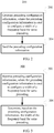
- a precoding configuration method is provided, where the method includes:
- the precoding configuration information is generated and sent, so that a receive end device can determine, based on the precoding configuration information, the width of the frequency band for same precoding.
- the width of the frequency band for same precoding is determined based on only system bandwidth, while the width of the frequency band for same precoding can be flexibly determined in the technical solutions provided in the embodiments of the present invention, so that requirements of a wireless communications system can be met in diversified scenarios, and system performance can be effectively optimized in different scenarios.
- the precoding configuration information includes a frequency bandwidth parameter, where the width of the frequency band for same precoding is equal to the frequency bandwidth parameter multiplied by reference frequency bandwidth.
- the reference frequency bandwidth is equal to frequency bandwidth of a resource unit.
- the precoding configuration information includes a width value of the frequency band for same precoding or an index of the width value.
- the precoding configuration information includes an index of a width mapping rule, where the width mapping rule records a correspondence between system bandwidth and the width of the frequency band for same precoding.
- the precoding configuration information includes a width update parameter, where the width update parameter is used to update a current width of the frequency band for same precoding.
- a precoding configuration method includes:
- the precoding configuration information is received, so that a receive end device can determine, based on the precoding configuration information, the width of the frequency band for same precoding.
- the width of the frequency band for same precoding is determined based on only system bandwidth, while the width of the frequency band for same precoding can be flexibly determined in the technical solutions provided in the embodiments of the present invention, so that requirements of a wireless communications system can be met in diversified scenarios, and system performance can be effectively optimized in different scenarios.
- the precoding configuration information includes a frequency bandwidth parameter; and the determining, based on the precoding configuration information, the width of the frequency band for same precoding includes that: the width of the frequency band for same precoding is equal to the frequency bandwidth parameter multiplied by reference frequency bandwidth.
- the reference frequency bandwidth is equal to frequency bandwidth of a resource unit.
- the precoding configuration information includes a width value of the frequency band for same precoding or an index of the width value
- the precoding configuration information includes an index of a width mapping rule, where the width mapping rule of the frequency band for same precoding records a correspondence between system bandwidth and the width of the frequency band for same precoding; and the determining, based on the precoding configuration information, the width of the frequency band for same precoding includes: determining the width mapping rule based on the index of the width mapping rule, and then determining, based on the width mapping rule and the system bandwidth, the width of the frequency band for same precoding.
- the precoding configuration information includes a width update parameter; and the determining, based on the precoding configuration information, the width of the frequency band for same precoding includes: determining, based on the width update parameter, the width of the frequency band for same precoding.
- a transmit end device where the transmit end device includes:
- the precoding configuration information includes a frequency bandwidth parameter, where the width of the frequency band for same precoding is equal to the frequency bandwidth parameter multiplied by reference frequency bandwidth.
- the reference frequency bandwidth is equal to frequency bandwidth of a resource unit.
- the precoding configuration information includes a width value of the frequency band for same precoding or an index of the width value.
- the precoding configuration information includes an index of a width mapping rule, where the width mapping rule records a correspondence between system bandwidth and the width of the frequency band for same precoding.
- the precoding configuration information includes a width update parameter, where the width update parameter is used to update a current width of the frequency band for same precoding.
- a receive end device where the receive end device includes:
- the precoding configuration information includes a frequency bandwidth parameter; and the determining, based on the precoding configuration information, the width of the frequency band for same precoding includes that: the width of the frequency band for same precoding is equal to the frequency bandwidth parameter multiplied by reference frequency bandwidth.
- the reference frequency bandwidth is equal to frequency bandwidth of a resource unit.
- the precoding configuration information includes a width value of the frequency band for same precoding or an index of the width value
- the precoding configuration information includes an index of a width mapping rule, where the width mapping rule of the frequency band for same precoding records a correspondence between system bandwidth and the width of the frequency band for same precoding; and the determining, based on the precoding configuration information, the width of the frequency band for same precoding includes: determining the width mapping rule based on the index of the width mapping rule, and then determining, based on the width mapping rule and the system bandwidth, the width of the frequency band for same precoding.
- the precoding configuration information includes a width update parameter used to indicate the frequency band for same precoding; and the determining, based on the precoding configuration information, the width of the frequency band for same precoding includes: determining, based on the width update parameter, the width of the frequency band for same precoding.
- a precoding configuration system is provided.
- the precoding configuration system includes: the transmit end device according to any one of the third aspect or possible designs of the third aspect; and the receive end device according to any one of the fourth aspect or possible designs of the fourth aspect.
- the transmit end device According to the precoding configuration method, device, and system provided in the embodiments of the present invention, the transmit end device generates and sends the precoding configuration information, so that the receive end device can determine, based on the precoding configuration information, the width of the frequency band for same precoding.
- the width of the frequency band for same precoding is determined based on only system bandwidth, while the width of the frequency band for same precoding can be flexibly determined in the technical solutions provided in the embodiments of the present invention.
- the transmit end device may feed back, to the receive end device based on specific requirements in different scenarios, an optimal width of a frequency band for same precoding, so that requirements of the wireless communications system may be met in diversified scenarios, and system performance may be effectively optimized in different scenarios.
- precoding configuration information is sent, so that a receive end can determine, based on the precoding configuration information, a width of a frequency band for same precoding.
- the width of the frequency band for same precoding is determined based on only system bandwidth, while the width of the frequency band for same precoding can be flexibly determined in the technical solutions provided in the embodiments of the present invention, so that requirements of a wireless communications system can be met in diversified scenarios, and system performance can be effectively optimized in different scenarios.
- FIG. 1 is a schematic diagram of an example of a wireless communications network 100 according to an embodiment of the present invention.
- the wireless communications network 100 includes base stations 102 to 106 and terminal devices 108 to 122.
- the base stations 102 to 106 may communicate with each other over a backhaul (backhaul) link (indicated by straight lines between the base stations 102 to 106).
- the backhaul link may be a wired backhaul link (for example, an optical fiber or a copper cable), or may be a wireless backhaul link (for example, microwave).
- the terminal devices 108 to 122 may communicate with the corresponding base stations 102 to 106 over radio links (indicated by polygonal lines between the base stations 102 to 106 and the terminal devices 108 to 122).
- the base stations 102 to 106 are configured to provide a wireless access service for the terminal devices 108 to 122.
- each base station corresponds to one service coverage area (which may also be referred to as a cell, and is indicated by each elliptical area in FIG. 1 ).
- a terminal device that enters the area may communicate with the base station by using a radio signal, to receive a wireless access service provided by the base station.
- Service coverage areas of base stations may overlap, and a terminal device in an overlapping area may receive radio signals from a plurality of base stations. Therefore, the plurality of base stations may all serve the terminal device.
- the plurality of base stations may serve the terminal device in the overlapping area by using a coordinated multipoint (Coordinated multipoint, CoMP) technology.
- CoMP Coordinatd multipoint
- the terminal device 112 may receive radio signals from the base station 102 and the base station 104, and the base station 102 and the base station 104 may both serve the terminal device 112.
- the terminal device 120 may receive radio signals from the base stations 102, 104, and 106, and the base stations 102, 104, and 106 may all serve the terminal device 120.
- the base station may also be referred to as a NodeB (NodeB), an evolved NodeB (evolved NodeB, eNodeB), an access point (Access Point, AP), or the like.
- NodeB NodeB
- eNodeB evolved NodeB
- Access Point Access Point
- the base stations may alternatively be classified into a macro base station configured to provide a macro cell (Macro cell), a micro base station configured to provide a micro cell (Pico cell), and a femto base station configured to provide a femto cell (Femto cell).
- a future base station may have another name.
- the terminal devices 108 to 118 may be various wireless communications devices having a wireless communication function, for example but not limited to, a mobile cellular phone, a cordless phone, a personal digital assistant (Personal Digital Assistant, PDA), a smartphone, a notebook computer, a tablet computer, a wireless data card, a wireless modem (Modulator demodulator, Modem), and a wearable device such as a smartwatch.
- a wireless communication function for example but not limited to, a mobile cellular phone, a cordless phone, a personal digital assistant (Personal Digital Assistant, PDA), a smartphone, a notebook computer, a tablet computer, a wireless data card, a wireless modem (Modulator demodulator, Modem), and a wearable device such as a smartwatch.
- IOT Internet of Things
- an increasing quantity of devices that previously do not have a communication function for example but not limited to, household appliances, transportation equipment, tools, service devices, and service facilities, begin to obtain the wireless communication function by disposing a wireless
- each of the terminal devices 108 to 118 may also be referred to as a mobile station, a mobile device, a mobile terminal, a wireless terminal, a handheld device, a client, or the like.
- a plurality of antennas may be disposed on all the base stations 102 to 106 and the terminal devices 108 to 122, to support a MIMO (Multiple Input Multiple Output, Multiple Input Multiple Output) technology.
- the terminal devices 108 to 122 may support not only a single user MIMO (Single-User MIMO, SU-MIMO) technology but also multi-user MIMO (Multi-User MIMO, MU-MIMO).
- the MU-MIMO may be implemented based on a space division multiple access (Space Division Multiple Access, SDMA) technology.
- the base stations 102 to 106 and the terminal devices 108 to 122 may further flexibly support a single-input single-output (Single Input Single Output, SISO) technology, a single-input multiple-output (Single Input Multiple Output, SIMO) technology, and a multiple-input-single-output (Multiple Input Single Output, MISO) technology, to implement various diversity (for example but not limited to, transmit diversity and receive diversity) and multiplexing technologies.
- SISO single-input single-output
- SIMO single-input multiple-output
- MISO multiple-input-single-output
- the diversity technologies may include, for example but not limited to, a transmit diversity (Transmit Diversity, TD) technology and a receive diversity (Receive Diversity, RD) technology.
- the multiplexing technology may be a spatial multiplexing (Spatial Multiplexing) technology.
- the foregoing technologies may further include a plurality of implementation solutions.
- currently frequently-used transmit diversity may include diversity manners, for example but not limited to, space time transmit diversity (Space-Time Transmit Diversity, STTD), space-frequency transmit diversity (Space-Frequency Transmit Diversity, SFTD), time switched transmit diversity (Time Switched Transmit Diversity, TSTD), frequency switched transmit diversity (Frequency Switch Transmit Diversity, FSTD), orthogonal transmit diversity (Orthogonal Transmit Diversity, OTD), and cyclic delay diversity (Cyclic Delay Diversity, CDD), and diversity manners obtained after derivation, evolution, and combination of the foregoing diversity manners.
- space time transmit diversity Space-Time Transmit Diversity, STTD
- space-frequency transmit diversity Space-Frequency Transmit Diversity, SFTD
- time switched transmit diversity Time Switched Transmit Diversity, TSTD
- frequency switched transmit diversity Frequency Switch Transmit Diversity, FSTD
- orthogonal transmit diversity Orthogonal Transmit Diversity
- OTD orthogonal Transmit Diversity
- CDD cyclic delay diversity
- transmit diversity manners such as space time block coding (Space Time Block Coding, STBC), space frequency block coding (Space Frequency Block Coding, SFBC), and the CDD are used.
- space time block coding Space Time Block Coding, STBC
- space frequency block coding Space Frequency Block Coding, SFBC
- the base station 102 may communicate with the terminal devices 104 to 110 by using various wireless communications technologies, for example but not limited to, a Time Division Multiple Access (Time Division Multiple Access, TDMA) technology, a Frequency Division Multiple Access (Frequency Division Multiple Access, FDMA) technology, a Code Division Multiple Access (Code Division Multiple Access, CDMA) technology, a Time Division-Synchronous Code Division Multiple Access (Time Division-Synchronous Code Division Multiple Access, TD-SCDMA) technology, an orthogonal frequency division multiple access (Orthogonal FDMA, OFDMA) technology, a single carrier frequency division multiple access (Single Carrier FDMA, SC-FDMA) technology, a space division multiple access (Space Division Multiple Access, SDMA) technology, and technologies evolved and derived from these technologies.
- TDMA Time Division Multiple Access
- FDMA Frequency Division Multiple Access
- CDMA Code Division Multiple Access
- CDMA Code Division Multiple Access
- Time Division-Synchronous Code Division Multiple Access Time Division-Sy
- the foregoing wireless communications technologies are adopted as a radio access technology (Radio Access Technology, RAT) in numerous wireless communications standards, to construct various wireless communications systems (or networks) nowadays widely known to people, including but not limited to Global System for Mobile Communications (Global System for Mobile Communications, GSM), CDMA2000, Wideband CDMA (Wideband CDMA, WCDMA), Wi-Fi defined in the 802.11 series standard, Worldwide Interoperability for Microwave Access (Worldwide Interoperability for Microwave Access, WiMAX), Long Term Evolution (Long Term Evolution, LTE), LTE-Advanced (LTE-Advanced, LTE-A), and systems evolved from these wireless communications systems.
- the wireless communications network shown in FIG. 1 may be any system or network in the foregoing wireless communications systems. Unless otherwise specified, the technical solutions provided in the embodiments of the present invention may be applied to the foregoing wireless communications technologies and wireless communications systems. In addition, the terms "system” and “network” may be interchanged with each other.
- the wireless communications network 100 shown in FIG. 1 is only an example, and is not intended to limit the technical solutions of the present invention.
- the wireless communications network 100 further includes another device, for example but not limited to, a base station controller (Base Station Controller, BSC), and a quantity of base stations and a quantity of terminal devices may be set based on a specific requirement.
- BSC Base Station Controller
- FIG. 2 is a flowchart of an example of a precoding configuration method 200 according to an embodiment of the present invention.
- the method 200 may be performed by a transmit end device.
- the transmit end device may be, for example but not limited to, one of the terminal devices 108 to 122 or the base stations 102 to 106 in FIG. 1 .
- Step 202 Generate precoding configuration information, where the precoding configuration information is used to configure a width of a frequency band for same precoding.
- Step 204 Send the precoding configuration information.
- the same precoding in the method 200 refers to a process in which a same precoding matrix is used for precoding.
- the existing LTE standard is used as an example to introduce this concept.
- a physical resource block group PRG is used to indicate the width of the frequency band for same precoding.
- the width of the frequency band for same precoding in the method 200 is similar to that in the LTE system.
- the precoding configuration information may include a frequency bandwidth parameter.
- the width that is indicated by the precoding configuration information and that is of the frequency band for same precoding is equal to the frequency bandwidth parameter multiplied by reference frequency bandwidth.
- the reference frequency bandwidth is equal to frequency bandwidth of a resource unit.
- the resource unit may be a resource block (Resource Block, RB for short) in the LTE standard, or may be a newly defined unit similar to the RB.
- the frequency bandwidth parameter may be a specific value.
- the frequency bandwidth parameter is a value of 3, and the resource unit is represented as an RB in the LTE standard.
- the width that is indicated by the precoding configuration information and that is of the frequency band for same precoding is frequency bandwidth of three RBs.
- the width of the frequency band for same precoding is 540 kHz (3 ⁇ 12 ⁇ 15 kHz). It should be noted that in a specific implementation process, the reference frequency bandwidth may alternatively be another width, for example but not limited to, subcarrier spacing.
- the precoding configuration information may further include a width value of the frequency band for same precoding or an index of the width value.
- the width value or the index of the width value is used to determine the width of the frequency band for same precoding.
- the precoding configuration information generated by the transmit end device carries a specific width value used to indicate the width of the frequency band for same precoding.
- the width value may be 180 kHz, and the width value 180 kHz is a width of a frequency band for same precoding that is indicated by the transmit end device to a receive end device and that is optimal in a specific scenario.
- the mentioned scenario may be a high frequency scenario (with a carrier frequency greater than 6 GHz), a low frequency scenario (with a carrier frequency less than 6 GHz), or the like, and the scenario may be configured based on a specific requirement, and is not limited herein.
- the precoding configuration information generated by the transmit end device carries an index used to indicate a width value of a frequency band for same precoding.
- the receive end device can determine, based on a correspondence between the width value and the index that is agreed in advance, an optimal width that is indicated by the transmit end device to the receive end device and that is of the frequency band for same precoding.
- Table 1 Index Width 0 180 kHz 1 360 kHz 2 720 kHz 3 1080 kHz
- the precoding configuration information may further include an index of a width mapping rule.
- the width mapping rule records a correspondence between system bandwidth and the width of the frequency band for same precoding.
- the index of the width mapping rule is used to indicate the width mapping rule.
- the receive end device may determine, based on the width mapping rule and the system bandwidth, the width of the frequency band for same precoding.
- the precoding configuration information generated by the transmit end device carries an index used to indicate a width mapping rule, and the width mapping rule is determined by using the index.
- the mapping rule may be expressed in a form of a table, or may be expressed in another form.
- the LTE standard is used as an example.
- the index is represented as idx
- the width of the frequency band for same precoding is represented as P
- the frequency bandwidth is expressed in a quantity of physical resource blocks PRBs in the prior art.
- the correspondence between the system bandwidth and the width of the frequency band for same precoding is determined based on a value of the index idx. For example, a value of idx is 0, the system bandwidth is 11 PRBs to 26 PRBs, and P is equal to two PRBs, namely, 360 kHz.
- Table 2 P (PRBs)
- System bandwidth N RB DL idx 0
- idx 1 ⁇ 10 1 2 11-26 2 3 27-63 3 4 64-110 2 4
- the precoding configuration information may further include a width update parameter.
- the width update parameter is used to update a current width of the frequency band for same precoding.
- precoding configuration information generated by the transmit end device carries a width update parameter, and the width update parameter is used to indicate a required update on the current width of the frequency band for same precoding.
- Specific update content may be expressed in a form of a calculation formula.
- Table 3 below (for ease of description, the width update parameter is represented as CASE, the current width of the frequency band for same precoding is represented as P, an updated width of the frequency band is represented as P*, and the frequency bandwidth is expressed in a quantity of physical resource blocks PRBs in the prior art).
- An updated width that is corresponding to the system bandwidth and that is of the frequency band for same precoding is determined based on a value of the width update parameter CASE (for example, the value of CASE is 0 or 1).
- CASE the width update parameter
- the transmit end device sends the foregoing precoding configuration information to the receive end device by using a determined resource.
- the precoding configuration information may be sent by using one of the following types of signaling:
- the physical layer signaling is also referred to as Layer 1 (Layer 1, LI) signaling, and may usually be carried in a control portion of a physical layer frame.
- a typical example of the L1 signaling is downlink control information (Downlink Control Information, DCI) carried in a physical downlink control channel (Physical Downlink Control Channel, PDCCH) defined in the LTE standard.
- DCI Downlink Control Information
- PDCCH Physical Downlink Control Channel
- the L1 signaling may alternatively be carried in a data portion of the physical layer frame. It can be easily learned that, a transmission period or a signaling period of the L1 signaling is usually a period of the physical layer frame. Therefore, such signaling is usually used to implement some dynamic control, to transmit some frequently changing information. For example, the physical layer signaling may be used to transfer resource allocation information.
- the media access control (Media Access Control, MAC) layer signaling belongs to Layer 2 (Layer 2) signaling, and may usually be carried in, for example but not limited to, a frame header of a Layer 2 frame.
- the frame header may further carry information, for example but not limited to, information such as a source address and a destination address.
- the Layer 2 frame usually further includes a frame body, in addition to the frame header. In some cases, the L2 signaling may alternatively be carried in the frame body of the Layer 2 frame.
- a typical example of the Layer 2 signaling is signaling carried in a frame control (Frame Control) field a frame header of a MAC frame in the 802.11 series standard, or a MAC control entity (Control Entity, MAC) defined in some protocols.
- the Layer 2 frame may usually be carried in the data portion of the physical layer frame.
- the precoding configuration information may alternatively be sent by using another type of Layer 2 signaling other than the media access control layer signaling.
- the radio resource control (Radio Resource Control, RRC) signaling belongs to Layer 3 (Layer 3) signaling, and is usually some control messages.
- the L3 signaling may usually be carried in the frame body of a Layer 2 frame.
- the L3 signaling usually has a relatively long transmission period or control period, and is suitable for sending some information that does not frequently change.
- the L3 signaling is usually used to carry some configuration information.
- the precoding configuration information may alternatively be sent by using another type of Layer 3 signaling other than the RRC signaling.
- the foregoing is merely principle description of the physical layer signaling, the MAC layer signaling, the RRC signaling, the Layer 1 signaling, the Layer 2 signaling, and the Layer 3 signaling. For details about the three types of signaling, refer to the prior art. Therefore, details are not described in this specification.
- the precoding configuration information is sent by using signaling, so that a receive end can determine, based on the precoding configuration information, the width of the frequency band for same precoding.
- the width of the frequency band for same precoding is determined based on only the system bandwidth, while the width of the frequency band for same precoding can be flexibly determined in the technical solutions provided in the embodiments of the present invention. Therefore, by using the technical solutions provided in the embodiments of the present invention, the transmit end device feeds back, to the receive end device based on a specific requirement in a different scenario, an optimal width of a frequency band for same precoding, so that requirements of the wireless communications system can be met in diversified scenarios, and system performance can be effectively optimized in different scenarios.
- FIG. 3 is a flowchart of an example of a precoding configuration method 300 according to an embodiment of the present invention.
- the method 300 may be performed by a receive end device.
- the receive end device may be, for example but not limited to, one of the base stations 102 to 106 or the terminal devices 108 to 122 in FIG. 1 .
- Step 302 Receive precoding configuration information, where the precoding configuration information is used to configure a width of a frequency band for same precoding.
- Step 304 Determine, based on the precoding configuration information, the width of the frequency band for same precoding.
- the precoding configuration information may include a frequency bandwidth parameter, the width of the frequency band for same precoding is determined based on the frequency bandwidth parameter, and the width of the frequency band for same precoding is equal to the frequency bandwidth parameter multiplied by reference frequency bandwidth.
- a specific determining process of the width of the frequency band for same precoding is described in detail in the method 200. Details are not described herein again.
- the precoding configuration information may further include a width value of the frequency band for same precoding or an index of the width value.
- the width of the frequency band for same precoding is determined based on the width value or the index of the width value.
- the receive end device receives a specific width value.
- the width value may be 180 kHz.
- the width value 180 kHz is a width of a frequency band for same precoding that is indicated by the transmit end device to the receive end device and that is optimal in a specific scenario.
- the mentioned scenario may be a high frequency scenario (with a carrier frequency greater than 6 GHz), a low frequency scenario (with a carrier frequency less than 6 GHz), or the like, and the scenario may be configured based on a specific requirement, and is not limited herein.
- the receive end device receives an index used to indicate a width value of a frequency band for same precoding.
- the receive end device can determine, based on a correspondence between the width value and the index that is agreed in advance, an optimal width that is indicated by the transmit end device to the receive end device and that is of the frequency band for same precoding.
- the correspondence between the width value and the index refer to Table 1 in the method 200.
- an index is equal to 1
- a corresponding width value of the index is 360 kHz.
- the optimal width that is indicated by the transmit end device to the receive end device and that is of the frequency band for same precoding is 360 kHz.
- the precoding configuration information may further include an index of a width mapping rule.
- the width mapping rule records a correspondence between system bandwidth and the width of the frequency band for same precoding.
- the index of the width mapping rule is used to indicate the width mapping rule.
- the receive end device may determine, based on the width mapping rule and the system bandwidth, the width of the frequency band for same precoding. For example, the receive end device receives an index used to indicate a width mapping rule, and the width mapping rule is determined by using the index.
- the mapping rule may be expressed in a form of a table, or may be expressed in another form.
- the LTE standard is used as an example.
- the index is represented as idx
- the width of the frequency band for same precoding is represented as P
- the frequency bandwidth is expressed in a quantity of physical resource blocks PRBs in the prior art.
- the correspondence between the system bandwidth and the width of the frequency band for same precoding is determined based on a value of the index idx. For example, a value of idx is 0, the system bandwidth is 11 PRBs to 26 PRBs, and the width of the frequency band for same precoding is equal to two PRBs, namely, 360 kHz. In other words, in this case, the width that is indicated by the transmit end device to the receive end device and that is of the frequency band for same precoding is 360 kHz.
- the precoding configuration information may further include a width update parameter, and the width of the frequency band for same precoding is determined based on the width update parameter.
- the receive end device receives a width update parameter, and the width update parameter is used to indicate a required update on the current width of the frequency band for same precoding.
- Specific update content may be expressed in a form of a calculation formula.
- the width update parameter is represented as CASE
- the current width of the frequency band for same precoding is represented as P
- an updated width of the frequency band is represented as P*
- the frequency bandwidth is expressed in a quantity of physical resource blocks PRBs in the prior art).
- the receive end device may determine, based on the precoding configuration information sent by the transmit end device, the width of the frequency band for same precoding.
- the width of the frequency band for same precoding is determined based on only the system bandwidth, while the width of the frequency band for same precoding can be flexibly determined in the technical solutions provided in the embodiments of the present invention. Therefore, by using the technical solutions provided in the embodiments of the present invention, the receive end device receives precoding configuration information sent by the transmit end device based on different scenarios, to determine the width of the frequency band for same precoding, so that requirements of the wireless communications system can be met in diversified scenarios, and system performance can be effectively optimized in different scenarios.
- FIG. 4 is a schematic diagram of a logical structure of a transmit end device 400 according to an embodiment of the present invention.
- the transmit end device may be, for example but not limited to, one of the terminal devices 108 to 122 or the base stations 102 to 106 in FIG. 1 .
- the device 400 includes a generation module 402 and a sending module 404.
- the generation module 402 is configured to generate precoding configuration information, where the precoding configuration information is used to configure a width of a frequency band for same precoding.
- the sending module 404 is configured to send the precoding configuration information.
- the precoding configuration information may include a frequency bandwidth parameter, where the width of the frequency band for same precoding is equal to the frequency bandwidth parameter multiplied by reference frequency bandwidth, and the reference frequency bandwidth is equal to frequency bandwidth of a resource unit.
- the precoding configuration information may further include a width value of the frequency band for same precoding or an index of the width value, where the width value or the index of the width value is used to determine the width of the frequency band for same precoding.
- the precoding configuration information may further include an index of a width mapping rule, where the width mapping rule records a correspondence between system bandwidth and the width of the frequency band for same precoding, and the index of the width mapping rule is used to determine the width mapping rule.
- the precoding configuration information may further include a width update parameter, where the width update parameter is used to update a current width of the frequency band for same precoding.
- the device 400 is configured to perform the method 200 shown in FIG. 2 .
- Technical features related to the device 400 are described above in detail with reference to the accompanying drawings, for example but not limited to, FIG. 2 . Therefore, details are not described herein again.
- FIG. 5 is a schematic diagram of a logical structure of a receive end device 500 according to an embodiment of the present invention.
- the receive end device may be, for example but not limited to, one of the base stations 102 to 106 or the terminal devices 108 to 122 in FIG. 1 .
- the device 500 includes a receiving module 502 and a determining module 504.
- the receiving module 502 is configured to receive precoding configuration information, where the precoding configuration information is used to configure a width of a frequency band for same precoding.
- the determining module 504 is configured to determine, based on the precoding configuration information, the width of the frequency band for same precoding.
- the precoding configuration information may include a frequency bandwidth parameter, and the width of the frequency band for same precoding is determined based on the frequency bandwidth parameter.
- the width of the frequency band for same precoding is equal to the frequency bandwidth parameter multiplied by reference frequency bandwidth, and the reference frequency bandwidth is equal to frequency bandwidth of a resource unit.
- the precoding configuration information may further include a width value of the frequency band for same precoding or an index of the width value, and the width value or the index of the width value is used to determine the width of the frequency band for same precoding.
- the precoding configuration information may further include an index of a width mapping rule, the width mapping rule records a correspondence between system bandwidth and the width of the frequency band for same precoding, and the width of the frequency band for same precoding is determined based on the width mapping rule and the system bandwidth.
- the precoding configuration information may further include a width update parameter, and the width of the frequency band for same precoding is determined based on the width update parameter.
- the device 500 is a receive side device corresponding to the device 400, and is configured to perform the method 300 shown in FIG. 3 .
- Technical features related to the device 500 are described above in detail with reference to the accompanying drawings, for example but not limited to, FIG. 3 . Therefore, details are not described herein again.
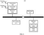
- FIG. 6 is a schematic diagram of a hardware structure of a transmit end device 600 according to an embodiment of the present invention.
- the device 600 includes a processor 602, a transceiver 604, a plurality of antennas 606, a memory 608, an I/O (input/output, Input/Output) interface 610, and a bus 612.
- the transceiver 604 further includes a transmitter 6042 and a receiver 6044.
- the memory 608 is further configured to store an instruction 6082 and data 6084.
- the processor 602, the transceiver 604, the memory 608, and the I/O interface 610 are communicatively connected to each other by using the bus 612.
- the plurality of antennas 606 are connected to the transceiver 604.
- the processor 602 may be a general purpose processor, for example but not limited to, a central processing unit (Central Processing Unit, CPU), or may be a dedicated processor, for example but not limited to, a digital signal processor (Digital Signal Processor, DSP), an application-specific integrated circuit (Application Specific Integrated Circuit, ASIC), or a field programmable gate array (Field Programmable Gate Array, FPGA).
- the processor 602 may alternatively be a combination of a plurality of processors.
- the processor 602 may be configured to perform, for example, step 202 in the precoding configuration method 200 shown in FIG. 2 and the operation performed by the generation module 402 in the transmit end device 400 shown in FIG. 4 .
- the processor 602 may be a processor specifically designed to perform the foregoing step and/or operation, or may be a processor that is configured to perform the foregoing step and/or operation by reading and executing the instruction 6062 stored in the memory 608.
- the processor 602 may need to use the data 6084 when performing the foregoing step and/or operation.
- the transceiver 604 includes the transmitter 6042 and the receiver 6044.
- the transmitter 6042 is configured to send a signal by using at least one of the plurality of antennas 606.
- the receiver 6044 is configured to receive a signal by using at least one of the plurality of antennas 606.
- the processor 6042 may be specifically configured to perform, by using at least one of the plurality of antennas 606, for example, step 204 in the precoding configuration method 200 shown in FIG. 2 and the operation performed by the sending module 404 in the transmit end device 400 shown in FIG. 4 .
- the memory 608 may be one of various types of storage media, for example, a random access memory (Random Access Memory, RAM), a read-only memory (Read Only Memory, ROM), a non-volatile RAM (Non-Volatile RAM, NVRAM), a programmable ROM (Programmable ROM, PROM), an erasable PROM (Erasable PROM, EPROM), an electrically erasable PROM (Electrically Erasable PROM, EEPROM), a flash memory, an optical memory, and a register.
- the memory 608 is specifically configured to store the instruction 6082 and the data 6084.
- the processor 602 may perform the foregoing step and/or operation by reading and executing the instruction 6082 stored in the memory 608, and may need to use the data 6084 when performing the foregoing step and/or operation.
- the I/O interface 610 is configured to receive an instruction and/or data from a peripheral device, and output an instruction and/or data to the peripheral device.
- the device 600 may further include other hardware devices. No further examples are enumerated in this specification.
- FIG. 7 is a schematic diagram of a hardware structure of a receive end device 700 according to an embodiment of the present invention.
- the device 700 includes a processor 702, a transceiver 704, a plurality of antennas 706, a memory 708, an I/O (input/output, Input/Output) interface 710, and a bus 712.
- the transceiver 704 further includes a transmitter 7042 and a receiver 7044.
- the memory 708 is further configured to store an instruction 7082 and data 7084.
- the processor 702, the transceiver 704, the memory 708, and the I/O interface 710 are communicatively connected to each other by using the bus 712.
- the plurality of antennas 706 are connected to the transceiver 704.
- the processor 702 may be a general purpose processor, for example but not limited to, a central processing unit (Central Processing Unit, CPU), or may be a dedicated processor, for example but not limited to, a digital signal processor (Digital Signal Processor, DSP), an application-specific integrated circuit (Application Specific Integrated Circuit, ASIC), or a field programmable gate array (Field Programmable Gate Array, FPGA).
- the processor 702 may alternatively be a combination of a plurality of processors.
- the processor 702 is configured to perform, for example, step 304 in the method 300 for receiving precoding configuration information shown in FIG.
- the processor 702 may be a processor specifically designed to perform the foregoing step and/or operation, or may be a processor that is configured to perform the foregoing step and/or operation by reading and executing the instruction 7082 stored in the memory 708.
- the processor 702 may need to use the data 7084 when performing the foregoing step and/or operation.
- the transceiver 704 includes the transmitter 7042 and the receiver 7044.
- the transmitter 7042 is configured to send a signal by using at least one of the plurality of antennas 706.
- the receiver 7044 is configured to receive a signal by using at least one of the plurality of antennas 706.
- the receiver 7044 may be specifically configured to perform, by using at least one of the plurality of antennas 706, for example, step 302 in the precoding configuration method 300 shown in FIG. 3 and the operation performed by the receiving module 502 in the receive end device 500 shown in FIG. 5 .
- the memory 708 may be one of various types of storage media, for example, a random access memory (Random Access Memory, RAM), a read-only memory (Read Only Memory, ROM), a non-volatile RAM (Non-Volatile RAM, NVRAM), a programmable ROM (Programmable ROM, PROM), an erasable PROM (Erasable PROM, EPROM), an electrically erasable PROM (Electrically Erasable PROM, EEPROM), a flash memory, an optical memory, and a register.
- the memory 708 is specifically configured to store the instruction 7082 and the data 7084.
- the processor 702 may perform the foregoing step and/or operation by reading and executing the instruction 7082 stored in the memory 708, and may need to use the data 7084 when performing the foregoing step and/or operation.
- the I/O interface 710 is configured to receive an instruction and/or data from a peripheral device, and output an instruction and/or data to the peripheral device.
- the device 700 may further include other hardware devices. No further examples are enumerated in this specification.
- FIG. 8 is a schematic structural diagram of a precoding configuration system 800 according to an embodiment of the present invention.
- the precoding configuration system 800 may include a transmit end device 810 and a receive end device 820.
- the transmit end device 810 is the transmit end device 400 shown in FIG. 4
- the receive end device 820 is the receive end device 500 shown in FIG. 5 .
- the transmit end device 810 is the transmit end device 600 shown in FIG. 6
- the receive end device 820 is the receive end device 700 shown in FIG. 7 .
- sequence numbers of the foregoing processes do not mean execution sequences in the embodiments of the present invention.
- the execution sequences of the processes should be determined based on functions and internal logic of the processes, and should not be construed as any limitation on the implementation processes of the embodiments of the present invention.
- the disclosed system, apparatus, and method may be implemented in other manners.
- the described apparatus embodiment is merely an example.
- the unit division is merely logical function division and may be other division during actual implementation.
- a plurality of units or components may be combined or integrated into another system, or some features may be ignored or not performed.
- the displayed or discussed mutual couplings or direct couplings or communications connections may be implemented by using some interfaces.
- the indirect couplings or communications connections between the apparatuses or units may be implemented electrically, mechanically or in other forms.
- the units described as separate parts may or may not be physically separate, and parts displayed as units may or may not be physical units, may be located in one position, or may be distributed on a plurality of network units. Some or all of the units may be selected based on actual requirements to achieve the objectives of the solutions of the embodiments.
- functional units in the embodiments of the present invention may be integrated into one processing unit, or each of the units may exist alone physically, or two or more units are integrated into one unit.
- the functions When the functions are implemented in the form of a software functional unit and sold or used as an independent product, the functions may be stored in a computer-readable storage medium. Based on such an understanding, the technical solutions of the present invention essentially, or the part contributing to the prior art, or some of the technical solutions may be implemented in a form of a software product.
- the computer software product is stored in a storage medium, and includes several instructions for instructing a computer device (which may be a personal computer, a server, a network device, or the like) to perform all or some of the steps of the methods described in the embodiments of the present invention.
- the foregoing storage medium includes: any medium that can store program code, such as a USB flash drive, a removable hard disk, a read-only memory (ROM, Read-Only Memory), a random access memory (RAM, Random Access Memory), a magnetic disk, or an optical disc.
- program code such as a USB flash drive, a removable hard disk, a read-only memory (ROM, Read-Only Memory), a random access memory (RAM, Random Access Memory), a magnetic disk, or an optical disc.
Landscapes
- Engineering & Computer Science (AREA)
- Signal Processing (AREA)
- Computer Networks & Wireless Communication (AREA)
- Physics & Mathematics (AREA)
- Mathematical Physics (AREA)
- Mobile Radio Communication Systems (AREA)
- Compression, Expansion, Code Conversion, And Decoders (AREA)
Description
- The present invention relates to the field of communications technologies, and in particular, to a precoding configuration method, device, and system.
- In a Multiple Input Multiple Output (English: Multiple Input Multiple Output, MIMO for short) system, by using multi-antenna precoding at a data transmit end, system performance may be effectively improved. To support a receive end in demodulating data, the transmit end usually needs to perform corresponding precoding on a demodulation reference signal (English: DeModulation Reference Signal, DMRS for short), so that the receive end can estimate a precoded equivalent channel.
- In a system based on orthogonal frequency division multiplexing (English: Orthogonal Frequency Division Multiplexing, OFDM for short), data is transmitted on a plurality of subcarriers in frequency domain. To avoid excessively consuming resources, the DMRS is transmitted on all subcarriers for data transmission, but is transmitted on some subcarriers corresponding to the DMRS. Therefore, data on a plurality of continuous subcarriers may be precoded by sharing one corresponding DMRS.
- Usually, a plurality of DMRSs in adjacent frequency domain may also use same precoding to improve channel estimation performance and reduce channel state information (English: Channel State Information, CSI for short) feedback overheads. Data that uses same precoding and a corresponding DMRS of the data are usually located on continuous subcarriers.
- In an existing Long Term Evolution (English: Long Term Evolution, LTE for short) system, a precoding resource block group (English: Precoding Resource block Group, PRG for short) is used to indicate a width of a frequency band for same precoding. The width of the frequency band for same precoding depends only on system bandwidth. Provided that the system bandwidth is determined, user equipment (English: User Equipment, UE for short) may determine, based on a convention of the LTE standard protocol, the width of the frequency band for same precoding.
- In a 5G multi-scenario condition, the width of the frequency band for same precoding is determined based on only the system bandwidth, causing poor flexibility and difficulty in effectively optimizing system performance in different scenario conditions.
- Document
US 2012/0008587 A1 provides a method and an apparatus for transmitting a signal in a wireless communication system. The method includes: generating R spatial streams each of which is generated on the basis of an information stream and a reference signal; generating N transmit streams on the basis of the R spatial streams and a precoding matrix (where R<N); mapping the N transmit streams to at least one resource block; and generating N signals from the N transmit streams mapped to the at least one resource block, and transmitting the N signals to a user equipment through respective antennas. - Document R1-1611037, "WF on phase continuity of DL/UL precoding", from Qualcomm, Huawei, HiSilicon, Xinwei, Ericsson, ZTE, ZTE Microelectronics and Intel, 3GPP TSG RAN WG1 Meeting #86bis, Lisbon, Portugal, 10th - 14th Oct 2016, Agenda item: 8.1.4.2, refers to phase continuity of DL/UL precoding. For both UL and DL, PRB bundling with configurable PRG sizes is studied, at least including following aspects: The size of PRG may or may not be fixed, or the size of PRG may or may not be system bandwidth dependent, or PRG may consist of all scheduled PRBs.
- Document Rl-1609771, "On PRB bundling for NR", from Ericsson, 3GPP TSG-RAN WG1 #86bis, Lisbon, Portugal, October 10 - 14, 2016, Agenda item: 8.1.4.4, refers to bundling that means that the scheduled PRBs are divided into a number of PRB Groups (PRG). Over each group, the UE may assume that the same pre-coder is applied, guaranteeing that there are no phase discontinuities in the effective channel over these PRBs. This improves the performance of DMRS based channel estimation, since filtering can be performed over a whole PRG, leading to a larger processing gain and that excessive edge effects can be avoided. For frequency selective precoding, there is a clear advantage of adopting the PRB bundling concept for NR, but there are situations where bundling may be limiting system performance. For such scenarios, handling the entire scheduled bandwidth as a bundle is preferable.
- The present invention is defined by the attached set of claims.
- To flexibly determine a width of a frequency band for same precoding and effectively optimize system performance in different scenario conditions, embodiments of the present invention provide a precoding configuration method, device, and system. The technical solutions are as follows:
According to a first aspect, a precoding configuration method is provided, where the method includes: - generating precoding configuration information, where the precoding configuration information is used to configure a width of a frequency band for same precoding; and
- sending the precoding configuration information.
- In the precoding configuration method provided in the embodiments of the present invention, the precoding configuration information is generated and sent, so that a receive end device can determine, based on the precoding configuration information, the width of the frequency band for same precoding. In the prior art, the width of the frequency band for same precoding is determined based on only system bandwidth, while the width of the frequency band for same precoding can be flexibly determined in the technical solutions provided in the embodiments of the present invention, so that requirements of a wireless communications system can be met in diversified scenarios, and system performance can be effectively optimized in different scenarios.
- In a possible design, the precoding configuration information includes a frequency bandwidth parameter, where the width of the frequency band for same precoding is equal to the frequency bandwidth parameter multiplied by reference frequency bandwidth.
- The reference frequency bandwidth is equal to frequency bandwidth of a resource unit.
- In a possible design, the precoding configuration information includes a width value of the frequency band for same precoding or an index of the width value.
- In a possible design, the precoding configuration information includes an index of a width mapping rule, where the width mapping rule records a correspondence between system bandwidth and the width of the frequency band for same precoding.
- In a possible design, the precoding configuration information includes a width update parameter, where the width update parameter is used to update a current width of the frequency band for same precoding.
- According to a second aspect, a precoding configuration method is provided, where the method includes:
- receiving precoding configuration information, where the precoding configuration information is used to configure a width of a frequency band for same precoding; and
- determining, based on the precoding configuration information, the width of the frequency band for same precoding.
- In the precoding configuration method provided in the embodiments of the present invention, the precoding configuration information is received, so that a receive end device can determine, based on the precoding configuration information, the width of the frequency band for same precoding. In the prior art, the width of the frequency band for same precoding is determined based on only system bandwidth, while the width of the frequency band for same precoding can be flexibly determined in the technical solutions provided in the embodiments of the present invention, so that requirements of a wireless communications system can be met in diversified scenarios, and system performance can be effectively optimized in different scenarios.
- In a possible design, the precoding configuration information includes a frequency bandwidth parameter; and the determining, based on the precoding configuration information, the width of the frequency band for same precoding includes that: the width of the frequency band for same precoding is equal to the frequency bandwidth parameter multiplied by reference frequency bandwidth.
- The reference frequency bandwidth is equal to frequency bandwidth of a resource unit.
- In a possible design, the precoding configuration information includes a width value of the frequency band for same precoding or an index of the width value; and
- the determining, based on the precoding configuration information, the width of the frequency band for same precoding includes: determining the width value of the frequency band for same precoding as the width of the frequency band for same precoding; or
- determining, based on a correspondence between an index of the width value of the frequency band for same precoding and the width value of the frequency band, the width of the frequency band for same precoding.
- In a possible design, the precoding configuration information includes an index of a width mapping rule, where the width mapping rule of the frequency band for same precoding records a correspondence between system bandwidth and the width of the frequency band for same precoding; and
the determining, based on the precoding configuration information, the width of the frequency band for same precoding includes: determining the width mapping rule based on the index of the width mapping rule, and then determining, based on the width mapping rule and the system bandwidth, the width of the frequency band for same precoding. - In a possible design, the precoding configuration information includes a width update parameter; and
the determining, based on the precoding configuration information, the width of the frequency band for same precoding includes: determining, based on the width update parameter, the width of the frequency band for same precoding. - According to a third aspect, a transmit end device is provided, where the transmit end device includes:
- a generation module, configured to generate precoding configuration information, where the precoding configuration information is used to configure a width of a frequency band for same precoding; and
- a sending module, configured to send the precoding configuration information.
- In a possible design, the precoding configuration information includes a frequency bandwidth parameter, where the width of the frequency band for same precoding is equal to the frequency bandwidth parameter multiplied by reference frequency bandwidth.
- The reference frequency bandwidth is equal to frequency bandwidth of a resource unit.
- In a possible design, the precoding configuration information includes a width value of the frequency band for same precoding or an index of the width value.
- In a possible design, the precoding configuration information includes an index of a width mapping rule, where the width mapping rule records a correspondence between system bandwidth and the width of the frequency band for same precoding.
- In a possible design, the precoding configuration information includes a width update parameter, where the width update parameter is used to update a current width of the frequency band for same precoding.
- According to a fourth aspect, a receive end device is provided, where the receive end device includes:
- a receiving module, configured to receive precoding configuration information, where the precoding configuration information is used to configure a width of a frequency band for same precoding; and
- a determining module, configured to determine, based on the precoding configuration information, the width of the frequency band for same precoding.
- In a possible design, the precoding configuration information includes a frequency bandwidth parameter; and the determining, based on the precoding configuration information, the width of the frequency band for same precoding includes that: the width of the frequency band for same precoding is equal to the frequency bandwidth parameter multiplied by reference frequency bandwidth.
- The reference frequency bandwidth is equal to frequency bandwidth of a resource unit.
- In a possible design, the precoding configuration information includes a width value of the frequency band for same precoding or an index of the width value; and
- the determining, based on the precoding configuration information, the width of the frequency band for same precoding includes: determining the width value of the frequency band for same precoding as the width of the frequency band for same precoding; or
- determining, based on a correspondence between an index of the width value of the frequency band for same precoding and the width value of the frequency band, the width of the frequency band for same precoding.
- In a possible design, the precoding configuration information includes an index of a width mapping rule, where the width mapping rule of the frequency band for same precoding records a correspondence between system bandwidth and the width of the frequency band for same precoding; and
the determining, based on the precoding configuration information, the width of the frequency band for same precoding includes: determining the width mapping rule based on the index of the width mapping rule, and then determining, based on the width mapping rule and the system bandwidth, the width of the frequency band for same precoding. - In a possible design, the precoding configuration information includes a width update parameter used to indicate the frequency band for same precoding; and
the determining, based on the precoding configuration information, the width of the frequency band for same precoding includes: determining, based on the width update parameter, the width of the frequency band for same precoding. - According to a fifth aspect, a precoding configuration system is provided.
- In a possible implementation, the precoding configuration system includes: the transmit end device according to any one of the third aspect or possible designs of the third aspect; and the receive end device according to any one of the fourth aspect or possible designs of the fourth aspect.
- Beneficial effects brought by the technical solutions provided in the embodiments of the present invention are as follows:
According to the precoding configuration method, device, and system provided in the embodiments of the present invention, the transmit end device generates and sends the precoding configuration information, so that the receive end device can determine, based on the precoding configuration information, the width of the frequency band for same precoding. In the prior art, the width of the frequency band for same precoding is determined based on only system bandwidth, while the width of the frequency band for same precoding can be flexibly determined in the technical solutions provided in the embodiments of the present invention. Therefore, by using the technical solutions provided in the embodiments of the present invention, the transmit end device may feed back, to the receive end device based on specific requirements in different scenarios, an optimal width of a frequency band for same precoding, so that requirements of the wireless communications system may be met in diversified scenarios, and system performance may be effectively optimized in different scenarios. - To describe the technical solutions in the embodiments of the present invention more clearly, the following briefly describes the accompanying drawings required for describing the embodiments. Apparently, the accompanying drawings in the following description show merely some embodiments of the present invention, and a person of ordinary skill in the art may derive other drawings from these accompanying drawings without creative efforts.
-
FIG. 1 is a schematic diagram of an example of a wireless communications network according to an embodiment of the present invention; -
FIG. 2 is a schematic diagram of an example of a precoding configuration method according to an embodiment of the present invention; -
FIG. 3 is a flowchart of an example of a precoding configuration method according to an embodiment of the present invention; -
FIG. 4 is a schematic diagram of a logical structure of a transmit end device according to an embodiment of the present invention; -
FIG. 5 is a schematic diagram of a logical structure of a receive end device according to an embodiment of the present invention; -
FIG. 6 is a schematic diagram of a hardware structure of a transmit end device according to an embodiment of the present invention; -
FIG. 7 is a schematic diagram of a hardware structure of a receive end device according to an embodiment of the present invention; and -
FIG. 8 is a schematic structural diagram of a precoding configuration system according to an embodiment of the present invention. - In technical solutions provided in embodiments of the present invention, precoding configuration information is sent, so that a receive end can determine, based on the precoding configuration information, a width of a frequency band for same precoding. In the prior art, the width of the frequency band for same precoding is determined based on only system bandwidth, while the width of the frequency band for same precoding can be flexibly determined in the technical solutions provided in the embodiments of the present invention, so that requirements of a wireless communications system can be met in diversified scenarios, and system performance can be effectively optimized in different scenarios.
- The following describes in detail the technical solutions provided in the embodiments of the present invention with reference to corresponding accompanying drawings.
-
FIG. 1 is a schematic diagram of an example of awireless communications network 100 according to an embodiment of the present invention. As shown inFIG. 1 , thewireless communications network 100 includesbase stations 102 to 106 andterminal devices 108 to 122. Thebase stations 102 to 106 may communicate with each other over a backhaul (backhaul) link (indicated by straight lines between thebase stations 102 to 106). The backhaul link may be a wired backhaul link (for example, an optical fiber or a copper cable), or may be a wireless backhaul link (for example, microwave). Theterminal devices 108 to 122 may communicate with thecorresponding base stations 102 to 106 over radio links (indicated by polygonal lines between thebase stations 102 to 106 and theterminal devices 108 to 122). - The
base stations 102 to 106 are configured to provide a wireless access service for theterminal devices 108 to 122. Specifically, each base station corresponds to one service coverage area (which may also be referred to as a cell, and is indicated by each elliptical area inFIG. 1 ). A terminal device that enters the area may communicate with the base station by using a radio signal, to receive a wireless access service provided by the base station. Service coverage areas of base stations may overlap, and a terminal device in an overlapping area may receive radio signals from a plurality of base stations. Therefore, the plurality of base stations may all serve the terminal device. For example, the plurality of base stations may serve the terminal device in the overlapping area by using a coordinated multipoint (Coordinated multipoint, CoMP) technology. For example, as shown inFIG. 1 , there is an overlapping area between a service coverage area of thebase station 102 and a service coverage area of thebase station 104, and theterminal device 112 is located in the overlapping area. Therefore, theterminal device 112 may receive radio signals from thebase station 102 and thebase station 104, and thebase station 102 and thebase station 104 may both serve theterminal device 112. For another example, as shown inFIG. 1 , there is a common overlapping area among the service coverage area of thebase station 102, the service coverage area of thebase station 104, and a service coverage area of thebase station 106, and theterminal device 120 is located in the overlapping area. Therefore, theterminal device 120 may receive radio signals from thebase stations base stations terminal device 120. - Depending on a used wireless communications technology, the base station may also be referred to as a NodeB (NodeB), an evolved NodeB (evolved NodeB, eNodeB), an access point (Access Point, AP), or the like. In addition, depending on sizes of coverage areas of services provided by base stations, the base stations may alternatively be classified into a macro base station configured to provide a macro cell (Macro cell), a micro base station configured to provide a micro cell (Pico cell), and a femto base station configured to provide a femto cell (Femto cell). With continuous evolution of wireless communications technologies, a future base station may have another name.
- The
terminal devices 108 to 118 may be various wireless communications devices having a wireless communication function, for example but not limited to, a mobile cellular phone, a cordless phone, a personal digital assistant (Personal Digital Assistant, PDA), a smartphone, a notebook computer, a tablet computer, a wireless data card, a wireless modem (Modulator demodulator, Modem), and a wearable device such as a smartwatch. With rise of the Internet of Things (Internet of Things, IOT) technology, an increasing quantity of devices that previously do not have a communication function, for example but not limited to, household appliances, transportation equipment, tools, service devices, and service facilities, begin to obtain the wireless communication function by disposing a wireless communications unit, so that the devices access a wireless communications network and are remotely controlled. Such devices have the wireless communication function because the wireless communications unit is disposed on the devices, and therefore also fall within a scope of wireless communications devices. In addition, each of theterminal devices 108 to 118 may also be referred to as a mobile station, a mobile device, a mobile terminal, a wireless terminal, a handheld device, a client, or the like. - A plurality of antennas may be disposed on all the
base stations 102 to 106 and theterminal devices 108 to 122, to support a MIMO (Multiple Input Multiple Output, Multiple Input Multiple Output) technology. Further, theterminal devices 108 to 122 may support not only a single user MIMO (Single-User MIMO, SU-MIMO) technology but also multi-user MIMO (Multi-User MIMO, MU-MIMO). The MU-MIMO may be implemented based on a space division multiple access (Space Division Multiple Access, SDMA) technology. Because the plurality of antennas are disposed on thebase stations 102 to 106 and theterminal devices 108 to 122, thebase stations 102 to 106 and theterminal devices 108 to 122 may further flexibly support a single-input single-output (Single Input Single Output, SISO) technology, a single-input multiple-output (Single Input Multiple Output, SIMO) technology, and a multiple-input-single-output (Multiple Input Single Output, MISO) technology, to implement various diversity (for example but not limited to, transmit diversity and receive diversity) and multiplexing technologies. The diversity technologies may include, for example but not limited to, a transmit diversity (Transmit Diversity, TD) technology and a receive diversity (Receive Diversity, RD) technology. The multiplexing technology may be a spatial multiplexing (Spatial Multiplexing) technology. In addition, the foregoing technologies may further include a plurality of implementation solutions. For example, currently frequently-used transmit diversity may include diversity manners, for example but not limited to, space time transmit diversity (Space-Time Transmit Diversity, STTD), space-frequency transmit diversity (Space-Frequency Transmit Diversity, SFTD), time switched transmit diversity (Time Switched Transmit Diversity, TSTD), frequency switched transmit diversity (Frequency Switch Transmit Diversity, FSTD), orthogonal transmit diversity (Orthogonal Transmit Diversity, OTD), and cyclic delay diversity (Cyclic Delay Diversity, CDD), and diversity manners obtained after derivation, evolution, and combination of the foregoing diversity manners. For example, in a current LTE (Long Term Evolution, Long Term Evolution) standard, transmit diversity manners such as space time block coding (Space Time Block Coding, STBC), space frequency block coding (Space Frequency Block Coding, SFBC), and the CDD are used. - In addition, the
base station 102 may communicate with theterminal devices 104 to 110 by using various wireless communications technologies, for example but not limited to, a Time Division Multiple Access (Time Division Multiple Access, TDMA) technology, a Frequency Division Multiple Access (Frequency Division Multiple Access, FDMA) technology, a Code Division Multiple Access (Code Division Multiple Access, CDMA) technology, a Time Division-Synchronous Code Division Multiple Access (Time Division-Synchronous Code Division Multiple Access, TD-SCDMA) technology, an orthogonal frequency division multiple access (Orthogonal FDMA, OFDMA) technology, a single carrier frequency division multiple access (Single Carrier FDMA, SC-FDMA) technology, a space division multiple access (Space Division Multiple Access, SDMA) technology, and technologies evolved and derived from these technologies. The foregoing wireless communications technologies are adopted as a radio access technology (Radio Access Technology, RAT) in numerous wireless communications standards, to construct various wireless communications systems (or networks) nowadays widely known to people, including but not limited to Global System for Mobile Communications (Global System for Mobile Communications, GSM), CDMA2000, Wideband CDMA (Wideband CDMA, WCDMA), Wi-Fi defined in the 802.11 series standard, Worldwide Interoperability for Microwave Access (Worldwide Interoperability for Microwave Access, WiMAX), Long Term Evolution (Long Term Evolution, LTE), LTE-Advanced (LTE-Advanced, LTE-A), and systems evolved from these wireless communications systems. The wireless communications network shown inFIG. 1 may be any system or network in the foregoing wireless communications systems. Unless otherwise specified, the technical solutions provided in the embodiments of the present invention may be applied to the foregoing wireless communications technologies and wireless communications systems. In addition, the terms "system" and "network" may be interchanged with each other. - It should be noted that, the
wireless communications network 100 shown inFIG. 1 is only an example, and is not intended to limit the technical solutions of the present invention. A person skilled in the art should understand that, in a specific implementation process, thewireless communications network 100 further includes another device, for example but not limited to, a base station controller (Base Station Controller, BSC), and a quantity of base stations and a quantity of terminal devices may be set based on a specific requirement. -
FIG. 2 is a flowchart of an example of aprecoding configuration method 200 according to an embodiment of the present invention. In a specific implementation process, themethod 200 may be performed by a transmit end device. The transmit end device may be, for example but not limited to, one of theterminal devices 108 to 122 or thebase stations 102 to 106 inFIG. 1 . - Step 202: Generate precoding configuration information, where the precoding configuration information is used to configure a width of a frequency band for same precoding.
- Step 204: Send the precoding configuration information.
- The same precoding in the
method 200 refers to a process in which a same precoding matrix is used for precoding. To facilitate understanding of the width of the frequency band for same precoding, the existing LTE standard is used as an example to introduce this concept. In an LTE system, a physical resource block group PRG is used to indicate the width of the frequency band for same precoding. The width of the frequency band for same precoding in themethod 200 is similar to that in the LTE system. - In the
method 200, the precoding configuration information may include a frequency bandwidth parameter. In this case, the width that is indicated by the precoding configuration information and that is of the frequency band for same precoding is equal to the frequency bandwidth parameter multiplied by reference frequency bandwidth. Optionally, the reference frequency bandwidth is equal to frequency bandwidth of a resource unit. The resource unit may be a resource block (Resource Block, RB for short) in the LTE standard, or may be a newly defined unit similar to the RB. In addition, the frequency bandwidth parameter may be a specific value. For example, the frequency bandwidth parameter is a value of 3, and the resource unit is represented as an RB in the LTE standard. Then the width that is indicated by the precoding configuration information and that is of the frequency band for same precoding is frequency bandwidth of three RBs. To be specific, the width of the frequency band for same precoding is 540 kHz (3×12×15 kHz). It should be noted that in a specific implementation process, the reference frequency bandwidth may alternatively be another width, for example but not limited to, subcarrier spacing. - Preferably, in the
method 200, the precoding configuration information may further include a width value of the frequency band for same precoding or an index of the width value. The width value or the index of the width value is used to determine the width of the frequency band for same precoding. For example, the precoding configuration information generated by the transmit end device carries a specific width value used to indicate the width of the frequency band for same precoding. For example, the width value may be 180 kHz, and the width value 180 kHz is a width of a frequency band for same precoding that is indicated by the transmit end device to a receive end device and that is optimal in a specific scenario. The mentioned scenario may be a high frequency scenario (with a carrier frequency greater than 6 GHz), a low frequency scenario (with a carrier frequency less than 6 GHz), or the like, and the scenario may be configured based on a specific requirement, and is not limited herein. For another example, the precoding configuration information generated by the transmit end device carries an index used to indicate a width value of a frequency band for same precoding. After receiving the index, the receive end device can determine, based on a correspondence between the width value and the index that is agreed in advance, an optimal width that is indicated by the transmit end device to the receive end device and that is of the frequency band for same precoding. Specifically, for the correspondence between the width value and the index, refer to Table 1 below.Table 1 Index Width 0 180 kHz 1 360 kHz 2 720 kHz 3 1080 kHz - Preferably, in the
method 200, the precoding configuration information may further include an index of a width mapping rule. The width mapping rule records a correspondence between system bandwidth and the width of the frequency band for same precoding. The index of the width mapping rule is used to indicate the width mapping rule. In this case, the receive end device may determine, based on the width mapping rule and the system bandwidth, the width of the frequency band for same precoding. For example, the precoding configuration information generated by the transmit end device carries an index used to indicate a width mapping rule, and the width mapping rule is determined by using the index. The mapping rule may be expressed in a form of a table, or may be expressed in another form. The LTE standard is used as an example. For the form of a table, refer to Table 2 below (for ease of description, the index is represented as idx, the width of the frequency band for same precoding is represented as P, and the frequency bandwidth is expressed in a quantity of physical resource blocks PRBs in the prior art). The correspondence between the system bandwidth and the width of the frequency band for same precoding is determined based on a value of the index idx. For example, a value of idx is 0, the system bandwidth is 11 PRBs to 26 PRBs, and P is equal to two PRBs, namely, 360 kHz.Table 2 P (PRBs) System bandwidth 
idx = 0 idx = 1 ≤10 1 2 11-26 2 3 27-63 3 4 64-110 2 4 - Preferably, in the
method 200, the precoding configuration information may further include a width update parameter. The width update parameter is used to update a current width of the frequency band for same precoding. For example, precoding configuration information generated by the transmit end device carries a width update parameter, and the width update parameter is used to indicate a required update on the current width of the frequency band for same precoding. Specific update content may be expressed in a form of a calculation formula. For details, refer to Table 3 below (for ease of description, the width update parameter is represented as CASE, the current width of the frequency band for same precoding is represented as P, an updated width of the frequency band is represented as P*, and the frequency bandwidth is expressed in a quantity of physical resource blocks PRBs in the prior art). An updated width that is corresponding to the system bandwidth and that is of the frequency band for same precoding is determined based on a value of the width update parameter CASE (for example, the value of CASE is 0 or 1).Table 3 P* (PRBs) System bandwidth 
Case 0 Case 1 ≤10 P* = P + 1 P* = P - 1 11-26 P* = P + 2 P* = P 27-63 P* = P × 2 P* = P/2 64-110 P* = P P* = P - In a specific implementation process, in
step 204, the transmit end device sends the foregoing precoding configuration information to the receive end device by using a determined resource. The precoding configuration information may be sent by using one of the following types of signaling: - physical layer signaling;
- media access control layer signaling; and
- radio resource control signaling.
- The physical layer signaling is also referred to as Layer 1 (Layer 1, LI) signaling, and may usually be carried in a control portion of a physical layer frame. A typical example of the L1 signaling is downlink control information (Downlink Control Information, DCI) carried in a physical downlink control channel (Physical Downlink Control Channel, PDCCH) defined in the LTE standard. In some cases, the L1 signaling may alternatively be carried in a data portion of the physical layer frame. It can be easily learned that, a transmission period or a signaling period of the L1 signaling is usually a period of the physical layer frame. Therefore, such signaling is usually used to implement some dynamic control, to transmit some frequently changing information. For example, the physical layer signaling may be used to transfer resource allocation information.
- The media access control (Media Access Control, MAC) layer signaling belongs to Layer 2 (Layer 2) signaling, and may usually be carried in, for example but not limited to, a frame header of a Layer 2 frame. The frame header may further carry information, for example but not limited to, information such as a source address and a destination address. The Layer 2 frame usually further includes a frame body, in addition to the frame header. In some cases, the L2 signaling may alternatively be carried in the frame body of the Layer 2 frame. A typical example of the Layer 2 signaling is signaling carried in a frame control (Frame Control) field a frame header of a MAC frame in the 802.11 series standard, or a MAC control entity (Control Entity, MAC) defined in some protocols. The Layer 2 frame may usually be carried in the data portion of the physical layer frame. The precoding configuration information may alternatively be sent by using another type of Layer 2 signaling other than the media access control layer signaling.
- The radio resource control (Radio Resource Control, RRC) signaling belongs to Layer 3 (Layer 3) signaling, and is usually some control messages. The L3 signaling may usually be carried in the frame body of a Layer 2 frame. The L3 signaling usually has a relatively long transmission period or control period, and is suitable for sending some information that does not frequently change. For example, in some existing communications standards, the L3 signaling is usually used to carry some configuration information. The precoding configuration information may alternatively be sent by using another type of Layer 3 signaling other than the RRC signaling. The foregoing is merely principle description of the physical layer signaling, the MAC layer signaling, the RRC signaling, the Layer 1 signaling, the Layer 2 signaling, and the Layer 3 signaling. For details about the three types of signaling, refer to the prior art. Therefore, details are not described in this specification.
- It can be easily learned that, the precoding configuration information is sent by using signaling, so that a receive end can determine, based on the precoding configuration information, the width of the frequency band for same precoding. In the prior art, the width of the frequency band for same precoding is determined based on only the system bandwidth, while the width of the frequency band for same precoding can be flexibly determined in the technical solutions provided in the embodiments of the present invention. Therefore, by using the technical solutions provided in the embodiments of the present invention, the transmit end device feeds back, to the receive end device based on a specific requirement in a different scenario, an optimal width of a frequency band for same precoding, so that requirements of the wireless communications system can be met in diversified scenarios, and system performance can be effectively optimized in different scenarios.
-
FIG. 3 is a flowchart of an example of aprecoding configuration method 300 according to an embodiment of the present invention. In a specific implementation process, themethod 300 may be performed by a receive end device. The receive end device may be, for example but not limited to, one of thebase stations 102 to 106 or theterminal devices 108 to 122 inFIG. 1 . - Step 302: Receive precoding configuration information, where the precoding configuration information is used to configure a width of a frequency band for same precoding.
- Step 304: Determine, based on the precoding configuration information, the width of the frequency band for same precoding.
- Concepts and other related features of the width of the frequency band for same precoding and the frequency bandwidth of the resource unit are described in detail in the
method 200. Details are not described herein again. - In the
method 300, the precoding configuration information may include a frequency bandwidth parameter, the width of the frequency band for same precoding is determined based on the frequency bandwidth parameter, and the width of the frequency band for same precoding is equal to the frequency bandwidth parameter multiplied by reference frequency bandwidth. A specific determining process of the width of the frequency band for same precoding is described in detail in themethod 200. Details are not described herein again. - Preferably, in the
method 300, the precoding configuration information may further include a width value of the frequency band for same precoding or an index of the width value. The width of the frequency band for same precoding is determined based on the width value or the index of the width value. For example, the receive end device receives a specific width value. For example, the width value may be 180 kHz. In this case, the width value 180 kHz is a width of a frequency band for same precoding that is indicated by the transmit end device to the receive end device and that is optimal in a specific scenario. The mentioned scenario may be a high frequency scenario (with a carrier frequency greater than 6 GHz), a low frequency scenario (with a carrier frequency less than 6 GHz), or the like, and the scenario may be configured based on a specific requirement, and is not limited herein. For another example, the receive end device receives an index used to indicate a width value of a frequency band for same precoding. In this case, after receiving the index, the receive end device can determine, based on a correspondence between the width value and the index that is agreed in advance, an optimal width that is indicated by the transmit end device to the receive end device and that is of the frequency band for same precoding. Specifically, for the correspondence between the width value and the index, refer to Table 1 in themethod 200. For example, an index is equal to 1, and a corresponding width value of the index is 360 kHz. In other words, the optimal width that is indicated by the transmit end device to the receive end device and that is of the frequency band for same precoding is 360 kHz. - Preferably, in the
method 300, the precoding configuration information may further include an index of a width mapping rule. The width mapping rule records a correspondence between system bandwidth and the width of the frequency band for same precoding. The index of the width mapping rule is used to indicate the width mapping rule. In this case, the receive end device may determine, based on the width mapping rule and the system bandwidth, the width of the frequency band for same precoding. For example, the receive end device receives an index used to indicate a width mapping rule, and the width mapping rule is determined by using the index. The mapping rule may be expressed in a form of a table, or may be expressed in another form. The LTE standard is used as an example. For the form of a table, refer to Table 2 in the method 200 (for ease of description, the index is represented as idx, the width of the frequency band for same precoding is represented as P, and the frequency bandwidth is expressed in a quantity of physical resource blocks PRBs in the prior art). The correspondence between the system bandwidth and the width of the frequency band for same precoding is determined based on a value of the index idx. For example, a value of idx is 0, the system bandwidth is 11 PRBs to 26 PRBs, and the width of the frequency band for same precoding is equal to two PRBs, namely, 360 kHz. In other words, in this case, the width that is indicated by the transmit end device to the receive end device and that is of the frequency band for same precoding is 360 kHz. - Preferably, in the
method 300, the precoding configuration information may further include a width update parameter, and the width of the frequency band for same precoding is determined based on the width update parameter. For example, the receive end device receives a width update parameter, and the width update parameter is used to indicate a required update on the current width of the frequency band for same precoding. Specific update content may be expressed in a form of a calculation formula. For details, refer to Table 3 in the method 200 (for ease of description, the width update parameter is represented as CASE, the current width of the frequency band for same precoding is represented as P, an updated width of the frequency band is represented as P*, and the frequency bandwidth is expressed in a quantity of physical resource blocks PRBs in the prior art). An updated width that is corresponding to the system bandwidth and that is of the frequency band for same precoding is determined based on a value of the width update parameter CASE. For example, when a value of CASE is 0 and the system bandwidth is set to 27 PRBs to 63 PRBs, a calculation formula used for the update content is P* = P × 2. To be specific, when the width of the frequency band for same precoding is two PRBs, a width that is updated by the receive end device and that is of the frequency band for same precoding is four PRBs. For example, when a value of CASE is 1 and the system bandwidth is 64 PRBs to 110 PRBs, a calculation formula used for the update content is P* = P. To be specific, when the width of the frequency band for same precoding is two PRBs, a width that is updated by the receive end device and that is of the frequency band for same precoding is also two PRBs. - It can be learned that the receive end device may determine, based on the precoding configuration information sent by the transmit end device, the width of the frequency band for same precoding. In the prior art, the width of the frequency band for same precoding is determined based on only the system bandwidth, while the width of the frequency band for same precoding can be flexibly determined in the technical solutions provided in the embodiments of the present invention. Therefore, by using the technical solutions provided in the embodiments of the present invention, the receive end device receives precoding configuration information sent by the transmit end device based on different scenarios, to determine the width of the frequency band for same precoding, so that requirements of the wireless communications system can be met in diversified scenarios, and system performance can be effectively optimized in different scenarios.
-
FIG. 4 is a schematic diagram of a logical structure of a transmitend device 400 according to an embodiment of the present invention. In a specific implementation process, the transmit end device may be, for example but not limited to, one of theterminal devices 108 to 122 or thebase stations 102 to 106 inFIG. 1 . As shown inFIG. 4 , thedevice 400 includes ageneration module 402 and a sendingmodule 404. - The
generation module 402 is configured to generate precoding configuration information, where the precoding configuration information is used to configure a width of a frequency band for same precoding. - The sending
module 404 is configured to send the precoding configuration information. - The precoding configuration information may include a frequency bandwidth parameter, where the width of the frequency band for same precoding is equal to the frequency bandwidth parameter multiplied by reference frequency bandwidth, and the reference frequency bandwidth is equal to frequency bandwidth of a resource unit.
- Preferably, the precoding configuration information may further include a width value of the frequency band for same precoding or an index of the width value, where the width value or the index of the width value is used to determine the width of the frequency band for same precoding.
- Preferably, the precoding configuration information may further include an index of a width mapping rule, where the width mapping rule records a correspondence between system bandwidth and the width of the frequency band for same precoding, and the index of the width mapping rule is used to determine the width mapping rule.
- Preferably, the precoding configuration information may further include a width update parameter, where the width update parameter is used to update a current width of the frequency band for same precoding.
- The
device 400 is configured to perform themethod 200 shown inFIG. 2 . Technical features related to thedevice 400 are described above in detail with reference to the accompanying drawings, for example but not limited to,FIG. 2 . Therefore, details are not described herein again. -
FIG. 5 is a schematic diagram of a logical structure of a receiveend device 500 according to an embodiment of the present invention. In a specific implementation process, the receive end device may be, for example but not limited to, one of thebase stations 102 to 106 or theterminal devices 108 to 122 inFIG. 1 . As shown inFIG. 5 , thedevice 500 includes a receivingmodule 502 and a determiningmodule 504. - The receiving
module 502 is configured to receive precoding configuration information, where the precoding configuration information is used to configure a width of a frequency band for same precoding. - The determining
module 504 is configured to determine, based on the precoding configuration information, the width of the frequency band for same precoding. - The precoding configuration information may include a frequency bandwidth parameter, and the width of the frequency band for same precoding is determined based on the frequency bandwidth parameter. The width of the frequency band for same precoding is equal to the frequency bandwidth parameter multiplied by reference frequency bandwidth, and the reference frequency bandwidth is equal to frequency bandwidth of a resource unit.
- Preferably, the precoding configuration information may further include a width value of the frequency band for same precoding or an index of the width value, and the width value or the index of the width value is used to determine the width of the frequency band for same precoding.
- Preferably, the precoding configuration information may further include an index of a width mapping rule, the width mapping rule records a correspondence between system bandwidth and the width of the frequency band for same precoding, and the width of the frequency band for same precoding is determined based on the width mapping rule and the system bandwidth. Preferably, the precoding configuration information may further include a width update parameter, and the width of the frequency band for same precoding is determined based on the width update parameter.
- The
device 500 is a receive side device corresponding to thedevice 400, and is configured to perform themethod 300 shown inFIG. 3 . Technical features related to thedevice 500 are described above in detail with reference to the accompanying drawings, for example but not limited to,FIG. 3 . Therefore, details are not described herein again. -
FIG. 6 is a schematic diagram of a hardware structure of a transmitend device 600 according to an embodiment of the present invention. As shown inFIG. 6 , thedevice 600 includes aprocessor 602, atransceiver 604, a plurality ofantennas 606, amemory 608, an I/O (input/output, Input/Output)interface 610, and abus 612. Thetransceiver 604 further includes atransmitter 6042 and areceiver 6044. Thememory 608 is further configured to store aninstruction 6082 anddata 6084. In addition, theprocessor 602, thetransceiver 604, thememory 608, and the I/O interface 610 are communicatively connected to each other by using thebus 612. The plurality ofantennas 606 are connected to thetransceiver 604. - The
processor 602 may be a general purpose processor, for example but not limited to, a central processing unit (Central Processing Unit, CPU), or may be a dedicated processor, for example but not limited to, a digital signal processor (Digital Signal Processor, DSP), an application-specific integrated circuit (Application Specific Integrated Circuit, ASIC), or a field programmable gate array (Field Programmable Gate Array, FPGA). In addition, theprocessor 602 may alternatively be a combination of a plurality of processors. Specifically, in the technical solutions provided in the embodiments of the present invention, theprocessor 602 may be configured to perform, for example,step 202 in theprecoding configuration method 200 shown inFIG. 2 and the operation performed by thegeneration module 402 in the transmitend device 400 shown inFIG. 4 . Theprocessor 602 may be a processor specifically designed to perform the foregoing step and/or operation, or may be a processor that is configured to perform the foregoing step and/or operation by reading and executing the instruction 6062 stored in thememory 608. Theprocessor 602 may need to use thedata 6084 when performing the foregoing step and/or operation. - The
transceiver 604 includes thetransmitter 6042 and thereceiver 6044. Thetransmitter 6042 is configured to send a signal by using at least one of the plurality ofantennas 606. Thereceiver 6044 is configured to receive a signal by using at least one of the plurality ofantennas 606. Specifically, in the technical solutions provided in the embodiments of the present invention, theprocessor 6042 may be specifically configured to perform, by using at least one of the plurality ofantennas 606, for example,step 204 in theprecoding configuration method 200 shown inFIG. 2 and the operation performed by the sendingmodule 404 in the transmitend device 400 shown inFIG. 4 . - The
memory 608 may be one of various types of storage media, for example, a random access memory (Random Access Memory, RAM), a read-only memory (Read Only Memory, ROM), a non-volatile RAM (Non-Volatile RAM, NVRAM), a programmable ROM (Programmable ROM, PROM), an erasable PROM (Erasable PROM, EPROM), an electrically erasable PROM (Electrically Erasable PROM, EEPROM), a flash memory, an optical memory, and a register. Thememory 608 is specifically configured to store theinstruction 6082 and thedata 6084. Theprocessor 602 may perform the foregoing step and/or operation by reading and executing theinstruction 6082 stored in thememory 608, and may need to use thedata 6084 when performing the foregoing step and/or operation. - The I/
O interface 610 is configured to receive an instruction and/or data from a peripheral device, and output an instruction and/or data to the peripheral device. - It should be noted that in a specific implementation process, the
device 600 may further include other hardware devices. No further examples are enumerated in this specification. -
FIG. 7 is a schematic diagram of a hardware structure of a receiveend device 700 according to an embodiment of the present invention. As shown inFIG. 7 , thedevice 700 includes aprocessor 702, atransceiver 704, a plurality ofantennas 706, amemory 708, an I/O (input/output, Input/Output)interface 710, and abus 712. Thetransceiver 704 further includes atransmitter 7042 and areceiver 7044. Thememory 708 is further configured to store aninstruction 7082 anddata 7084. In addition, theprocessor 702, thetransceiver 704, thememory 708, and the I/O interface 710 are communicatively connected to each other by using thebus 712. The plurality ofantennas 706 are connected to thetransceiver 704. - The
processor 702 may be a general purpose processor, for example but not limited to, a central processing unit (Central Processing Unit, CPU), or may be a dedicated processor, for example but not limited to, a digital signal processor (Digital Signal Processor, DSP), an application-specific integrated circuit (Application Specific Integrated Circuit, ASIC), or a field programmable gate array (Field Programmable Gate Array, FPGA). In addition, theprocessor 702 may alternatively be a combination of a plurality of processors. Specifically, in the technical solutions provided in the embodiments of the present invention, theprocessor 702 is configured to perform, for example,step 304 in themethod 300 for receiving precoding configuration information shown inFIG. 3 and the operation performed by the determiningmodule 504 in thedevice 500 for receiving precoding configuration information shown inFIG. 5 . Theprocessor 702 may be a processor specifically designed to perform the foregoing step and/or operation, or may be a processor that is configured to perform the foregoing step and/or operation by reading and executing theinstruction 7082 stored in thememory 708. Theprocessor 702 may need to use thedata 7084 when performing the foregoing step and/or operation. - The
transceiver 704 includes thetransmitter 7042 and thereceiver 7044. Thetransmitter 7042 is configured to send a signal by using at least one of the plurality ofantennas 706. Thereceiver 7044 is configured to receive a signal by using at least one of the plurality ofantennas 706. Specifically, in the technical solutions provided in the embodiments of the present invention, thereceiver 7044 may be specifically configured to perform, by using at least one of the plurality ofantennas 706, for example,step 302 in theprecoding configuration method 300 shown inFIG. 3 and the operation performed by the receivingmodule 502 in the receiveend device 500 shown inFIG. 5 . - The
memory 708 may be one of various types of storage media, for example, a random access memory (Random Access Memory, RAM), a read-only memory (Read Only Memory, ROM), a non-volatile RAM (Non-Volatile RAM, NVRAM), a programmable ROM (Programmable ROM, PROM), an erasable PROM (Erasable PROM, EPROM), an electrically erasable PROM (Electrically Erasable PROM, EEPROM), a flash memory, an optical memory, and a register. Thememory 708 is specifically configured to store theinstruction 7082 and thedata 7084. Theprocessor 702 may perform the foregoing step and/or operation by reading and executing theinstruction 7082 stored in thememory 708, and may need to use thedata 7084 when performing the foregoing step and/or operation. - The I/
O interface 710 is configured to receive an instruction and/or data from a peripheral device, and output an instruction and/or data to the peripheral device. - It should be noted that in specific implementation process, the
device 700 may further include other hardware devices. No further examples are enumerated in this specification. -
FIG. 8 is a schematic structural diagram of aprecoding configuration system 800 according to an embodiment of the present invention. In a specific implementation process, as shown inFIG. 8 , theprecoding configuration system 800 may include a transmitend device 810 and a receiveend device 820. - In a possible implementation, the transmit
end device 810 is the transmitend device 400 shown inFIG. 4 , and the receiveend device 820 is the receiveend device 500 shown inFIG. 5 . - In another possible implementation, the transmit
end device 810 is the transmitend device 600 shown inFIG. 6 , and the receiveend device 820 is the receiveend device 700 shown inFIG. 7 . - The foregoing descriptions are merely example embodiments of the present invention, but are not intended to limit the present invention. For example, other processing steps are added before, between, and/or after the steps of the methods provided in the embodiments of the present invention, and other processing modules are added into the apparatuses provided in the embodiments of the present invention to complete additional processing. Any application of the technical solutions provided in the embodiments of the present invention in a specific scenario or a specific condition shall be considered as further improvement made based on the technical solutions provided in the embodiments of the present invention, thereby falling within the scope of the present invention defined in the claims.
- It should be understood that sequence numbers of the foregoing processes do not mean execution sequences in the embodiments of the present invention. The execution sequences of the processes should be determined based on functions and internal logic of the processes, and should not be construed as any limitation on the implementation processes of the embodiments of the present invention.
- A person of ordinary skill in the art may be aware that, with reference to the examples described in the embodiments disclosed in this specification, units and algorithm steps may be implemented by electronic hardware or a combination of computer software and electronic hardware. Whether the functions are performed by hardware or software depends on specific applications and design constraint conditions of the technical solutions. A person skilled in the art may use different methods to implement the described functions for each specific application, but it should not be considered that the implementation goes beyond the scope of the present invention as defined in the claims.
- It may be clearly understood by a person skilled in the art that, for the purpose of convenient and brief description, for a detailed working process of the foregoing system, apparatus, and unit, refer to a corresponding process in the foregoing method embodiments. Details are not described herein again.
- In the several embodiments provided in this application, it should be understood that the disclosed system, apparatus, and method may be implemented in other manners. For example, the described apparatus embodiment is merely an example. For example, the unit division is merely logical function division and may be other division during actual implementation. For example, a plurality of units or components may be combined or integrated into another system, or some features may be ignored or not performed. In addition, the displayed or discussed mutual couplings or direct couplings or communications connections may be implemented by using some interfaces. The indirect couplings or communications connections between the apparatuses or units may be implemented electrically, mechanically or in other forms.
- The units described as separate parts may or may not be physically separate, and parts displayed as units may or may not be physical units, may be located in one position, or may be distributed on a plurality of network units. Some or all of the units may be selected based on actual requirements to achieve the objectives of the solutions of the embodiments.
- In addition, functional units in the embodiments of the present invention may be integrated into one processing unit, or each of the units may exist alone physically, or two or more units are integrated into one unit.
- When the functions are implemented in the form of a software functional unit and sold or used as an independent product, the functions may be stored in a computer-readable storage medium. Based on such an understanding, the technical solutions of the present invention essentially, or the part contributing to the prior art, or some of the technical solutions may be implemented in a form of a software product. The computer software product is stored in a storage medium, and includes several instructions for instructing a computer device (which may be a personal computer, a server, a network device, or the like) to perform all or some of the steps of the methods described in the embodiments of the present invention. The foregoing storage medium includes: any medium that can store program code, such as a USB flash drive, a removable hard disk, a read-only memory (ROM, Read-Only Memory), a random access memory (RAM, Random Access Memory), a magnetic disk, or an optical disc.
- The foregoing descriptions are merely specific implementations of the present invention, but are not intended to limit the protection scope of the present invention. Any variation or replacement readily figured out by a person skilled in the art within the technical scope disclosed in the present invention shall fall within the protection scope of the present invention. Therefore, the protection scope of the present invention shall be subject to the protection scope of the claims.
Claims (5)
- A transmit end device (400, 600, 810), wherein the transmit end device (400, 600, 810) comprises:a generation module (402), configured to generate precoding configuration information, wherein the precoding configuration information is used to configure a width of a frequency band for same precoding; anda sending module (404), configured to send the precoding configuration information,characterized in that the precoding configuration information comprises a width update parameter, wherein the width update parameter is used to update a current width of the frequency band for same precoding,wherein update content is expressed in a form of a calculation formula as defined in the following table, wherein the width update parameter is represented as CASE, a current width of the frequency band for same precoding is represented as P, an updated width of the frequency band is represented as P*, and a frequency bandwidth of a system bandwidth is expressed in a quantity

P* (PRBs) System bandwidth 
CASE = 0 CASE = 1 ≤10 P* =P + 1 P* = P - 1 11-26 P* = P + 2 P* = P 27-63 P* = P × 2 P* = P/2 64-110 P* = P P* = P - A receive end device (500, 700, 820), wherein the receive end device (500, 700, 820) comprises:a receiving module (502), configured to receive precoding configuration information, wherein the precoding configuration information is used to configure a width of a frequency band for same precoding; anda determining module (504), configured to determine, based on the precoding configuration information, the width of the frequency band for same precoding,characterized in that the precoding configuration information comprises a width update parameter; andthe determining, based on the precoding configuration information, the width of the frequency band for same precoding comprises: determining, based on the width update parameter, the width of the frequency band for same precoding,wherein update content is expressed in a form of a calculation formula as defined in the following table, wherein the width update parameter is represented as CASE, a current width of the frequency band for same precoding is represented as P, an updated width of the frequency band is represented as P*, and a frequency bandwidth of a system bandwidth is expressed in a quantity

P* (PRBs) System bandwidth 
CASE = 0 CASE = 1 ≤10 P* = P + 1 P* = P - 1 11-26 P* = P + 2 P* = P 27-63 P* = P × 2 P* = P/2 64-110 P* = P P* = P - A precoding configuration system (800), wherein the precoding configuration system comprises:the transmit end device (400, 600, 810) according to claim 1; andthe receive end device (500, 700, 820) according to claim 2.
- A precoding configuration method, wherein the method comprises:generating (202) precoding configuration information, wherein the precoding configuration information is used to configure a width of a frequency band for same precoding; andsending (204) the precoding configuration information,characterized in that the precoding configuration information comprises a width update parameter, wherein the width update parameter is used to update a current width of the frequency band for same precoding,wherein update content is expressed in a form of a calculation formula as defined in the following table, wherein the width update parameter is represented as CASE, a current width of the frequency band for same precoding is represented as P, an updated width of the frequency band is represented as P*, and a frequency bandwidth of a system bandwidth is expressed in a quantity

P* (PRBs) System bandwidth 
CASE = 0 CASE = 1 ≤10 P* =P + 1 P* = P - 1 11-26 P* = P + 2 P* = P 27-63 P* = P × 2 P* = P/2 64-110 P* = P P* = P - A precoding configuration method, wherein the method comprises:receiving (302) precoding configuration information, wherein the precoding configuration information is used to configure a width of a frequency band for same precoding; anddetermining (304), based on the precoding configuration information, the width of the frequency band for same precoding,characterized in that the precoding configuration information comprises a width update parameter; andthe determining, based on the precoding configuration information, the width of the frequency band for same precoding comprises: determining, based on the width update parameter, the width of the frequency band for same precoding,wherein update content is expressed in a form of a calculation formula as defined in the following table, wherein the width update parameter is represented as CASE, a current width of the frequency band for same precoding is represented as P, an updated width of the frequency band is represented as P*, and a frequency bandwidth of a system bandwidth is expressed in a quantity

P* (PRBs) System bandwidth 
CASE = 0 CASE = 1 ≤10 P* = P + 1 P* = P - 1 11-26 P* = P + 2 P* = P 27-63 P* = P × 2 P* = P/2 64-110 P* = P P* = P
Applications Claiming Priority (2)
| Application Number | Priority Date | Filing Date | Title |
|---|---|---|---|
| CN201610974339.0A CN108023619B (en) | 2016-11-03 | 2016-11-03 | A precoding configuration method, device and system |
| PCT/CN2017/090052 WO2018082319A1 (en) | 2016-11-03 | 2017-06-26 | Precoding configuration method, device and system |
Publications (3)
| Publication Number | Publication Date |
|---|---|
| EP3528397A1 EP3528397A1 (en) | 2019-08-21 |
| EP3528397A4 EP3528397A4 (en) | 2019-09-11 |
| EP3528397B1 true EP3528397B1 (en) | 2021-01-20 |
Family
ID=62075671
Family Applications (1)
| Application Number | Title | Priority Date | Filing Date |
|---|---|---|---|
| EP17867269.7A Active EP3528397B1 (en) | 2016-11-03 | 2017-06-26 | Precoding configuration method, device and system |
Country Status (4)
| Country | Link |
|---|---|
| US (1) | US10972159B2 (en) |
| EP (1) | EP3528397B1 (en) |
| CN (1) | CN108023619B (en) |
| WO (1) | WO2018082319A1 (en) |
Family Cites Families (18)
| Publication number | Priority date | Publication date | Assignee | Title |
|---|---|---|---|---|
| KR100981514B1 (en) * | 2004-12-30 | 2010-09-10 | 삼성전자주식회사 | Adaptive Subchannel and Bit Allocation Method Using Partial Channel Information Feedback in Orthogonal Frequency Division Multiple Access Communication Systems |
| CN102571138B (en) * | 2005-12-20 | 2015-02-11 | Lg电子株式会社 | Method of generating code sequence and method of transmitting signal using the same |
| US8830983B2 (en) * | 2005-12-20 | 2014-09-09 | Lg Electronics Inc. | Method of generating code sequence and method of transmitting signal using the same |
| KR101382894B1 (en) * | 2007-03-12 | 2014-04-08 | 엘지전자 주식회사 | Method for transmitting control information in multiple antenna system |
| WO2010058245A1 (en) * | 2008-11-20 | 2010-05-27 | Nokia Corporation | Pre-coding for downlink control channel |
| KR101588731B1 (en) * | 2009-02-20 | 2016-01-26 | 엘지전자 주식회사 | In an uplink MIMO system to which SC-FDMA is applied, a PMI notification method |
| KR101753391B1 (en) * | 2009-03-30 | 2017-07-04 | 엘지전자 주식회사 | Method and apparatus of transmitting signal in wireless communication system |
| WO2011018102A1 (en) * | 2009-08-10 | 2011-02-17 | Nokia Siemens Networks Oy | Apparatus and method for n0n-c0debook based precoding |
| JP2011142538A (en) * | 2010-01-08 | 2011-07-21 | Sharp Corp | Base station device, mobile station device, radio communication system, control program for base station device, control program for mobile station device, and integrated circuit |
| EP2378703A1 (en) * | 2010-04-13 | 2011-10-19 | Panasonic Corporation | Mapping of control information to control channel elements |
| WO2012026706A2 (en) * | 2010-08-24 | 2012-03-01 | (주)팬택 | Method and device for transmitting and receiving reference signals in accordance with mimo operation mode |
| TWI468063B (en) * | 2011-01-07 | 2015-01-01 | Inst Information Industry | Base station and wireless device |
| US9401748B2 (en) * | 2012-03-27 | 2016-07-26 | Texas Instruments Incorporated | Method and apparatus for channel state information feedback in a coordinated multi-point communication system |
| CN105229955A (en) * | 2014-04-03 | 2016-01-06 | 华为技术有限公司 | A kind of CSI report method and apparatus |
| US20150305049A1 (en) * | 2014-04-21 | 2015-10-22 | Collision Communications, Inc. | Method And System For Improving Efficiency In A Cellular Communications Network |
| CN105245310B (en) * | 2014-07-09 | 2020-01-14 | 中兴通讯股份有限公司 | Method and system for processing downlink pilot signal |
| WO2016122437A1 (en) * | 2015-01-29 | 2016-08-04 | Intel IP Corporation | System and methods for precoded transmissions for narrowband transmissions within wider system bandwidth |
| CN105992343B (en) * | 2015-01-30 | 2020-05-26 | 电信科学技术研究院 | Signal sending method, receiving method and device |
-
2016
- 2016-11-03 CN CN201610974339.0A patent/CN108023619B/en active Active
-
2017
- 2017-06-26 WO PCT/CN2017/090052 patent/WO2018082319A1/en not_active Ceased
- 2017-06-26 EP EP17867269.7A patent/EP3528397B1/en active Active
-
2019
- 2019-05-02 US US16/401,824 patent/US10972159B2/en active Active
Non-Patent Citations (1)
| Title |
|---|
| None * |
Also Published As
| Publication number | Publication date |
|---|---|
| CN108023619B (en) | 2023-09-01 |
| WO2018082319A1 (en) | 2018-05-11 |
| BR112019008726A2 (en) | 2019-07-16 |
| US20190260437A1 (en) | 2019-08-22 |
| US10972159B2 (en) | 2021-04-06 |
| CN108023619A (en) | 2018-05-11 |
| EP3528397A4 (en) | 2019-09-11 |
| EP3528397A1 (en) | 2019-08-21 |
Similar Documents
| Publication | Publication Date | Title |
|---|---|---|
| CN110831198B (en) | Bandwidth resource switching method, instruction bandwidth resource switching method, terminal and network equipment | |
| EP3537813B1 (en) | Method for configuring frequency band for reporting channel state information and communication device | |
| US11791960B2 (en) | Resource configuration method and device | |
| EP4049500B1 (en) | Method and apparatus for coreset configuration of unlicensed bands | |
| EP3528417B1 (en) | Method for transmitting reference signal, network side device, and user equipment | |
| EP3553987B1 (en) | Method and apparatus for sending reference signal | |
| US11784770B2 (en) | Method and apparatus for sending reference signal, and method and apparatus for obtaining reference signal | |
| EP3562084B1 (en) | Method for sending reference signal, method for receiving reference signal, and related device | |
| EP3618313A1 (en) | Frequency band indicating method, frequency band determining method, transmitter device, and receiver device | |
| EP3672317A1 (en) | Method for channel measurement | |
| EP3703296B1 (en) | User equipment and access device | |
| WO2024007249A1 (en) | Performance of layer-1 (l1) measurement operations by a user equipment (ue) on l1 reference signals received by the ue outside of an active bandwidth part | |
| EP3528397B1 (en) | Precoding configuration method, device and system | |
| KR20240035809A (en) | Method and apparatus for full-duplex wireless communication system | |
| CN119968817A (en) | Method and system for enhanced beam management for multiple transmission and reception points | |
| CN121587073A (en) | Restriction of unicast DCI processing with multi-cell and single-cell scheduling |
Legal Events
| Date | Code | Title | Description |
|---|---|---|---|
| STAA | Information on the status of an ep patent application or granted ep patent |
Free format text: STATUS: THE INTERNATIONAL PUBLICATION HAS BEEN MADE |
|
| PUAI | Public reference made under article 153(3) epc to a published international application that has entered the european phase |
Free format text: ORIGINAL CODE: 0009012 |
|
| STAA | Information on the status of an ep patent application or granted ep patent |
Free format text: STATUS: REQUEST FOR EXAMINATION WAS MADE |
|
| 17P | Request for examination filed |
Effective date: 20190513 |
|
| AK | Designated contracting states |
Kind code of ref document: A1 Designated state(s): AL AT BE BG CH CY CZ DE DK EE ES FI FR GB GR HR HU IE IS IT LI LT LU LV MC MK MT NL NO PL PT RO RS SE SI SK SM TR |
|
| AX | Request for extension of the european patent |
Extension state: BA ME |
|
| A4 | Supplementary search report drawn up and despatched |
Effective date: 20190809 |
|
| RIC1 | Information provided on ipc code assigned before grant |
Ipc: H04B 7/06 20060101AFI20190805BHEP |
|
| DAV | Request for validation of the european patent (deleted) | ||
| DAX | Request for extension of the european patent (deleted) | ||
| STAA | Information on the status of an ep patent application or granted ep patent |
Free format text: STATUS: EXAMINATION IS IN PROGRESS |
|
| 17Q | First examination report despatched |
Effective date: 20200217 |
|
| GRAP | Despatch of communication of intention to grant a patent |
Free format text: ORIGINAL CODE: EPIDOSNIGR1 |
|
| STAA | Information on the status of an ep patent application or granted ep patent |
Free format text: STATUS: GRANT OF PATENT IS INTENDED |
|
| INTG | Intention to grant announced |
Effective date: 20200803 |
|
| GRAS | Grant fee paid |
Free format text: ORIGINAL CODE: EPIDOSNIGR3 |
|
| GRAA | (expected) grant |
Free format text: ORIGINAL CODE: 0009210 |
|
| STAA | Information on the status of an ep patent application or granted ep patent |
Free format text: STATUS: THE PATENT HAS BEEN GRANTED |
|
| AK | Designated contracting states |
Kind code of ref document: B1 Designated state(s): AL AT BE BG CH CY CZ DE DK EE ES FI FR GB GR HR HU IE IS IT LI LT LU LV MC MK MT NL NO PL PT RO RS SE SI SK SM TR |
|
| REG | Reference to a national code |
Ref country code: GB Ref legal event code: FG4D |
|
| REG | Reference to a national code |
Ref country code: CH Ref legal event code: EP |
|
| REG | Reference to a national code |
Ref country code: AT Ref legal event code: REF Ref document number: 1357248 Country of ref document: AT Kind code of ref document: T Effective date: 20210215 |
|
| REG | Reference to a national code |
Ref country code: IE Ref legal event code: FG4D |
|
| REG | Reference to a national code |
Ref country code: DE Ref legal event code: R096 Ref document number: 602017031882 Country of ref document: DE |
|
| REG | Reference to a national code |
Ref country code: NL Ref legal event code: MP Effective date: 20210120 |
|
| REG | Reference to a national code |
Ref country code: LT Ref legal event code: MG9D |
|
| REG | Reference to a national code |
Ref country code: AT Ref legal event code: MK05 Ref document number: 1357248 Country of ref document: AT Kind code of ref document: T Effective date: 20210120 |
|
| PG25 | Lapsed in a contracting state [announced via postgrant information from national office to epo] |
Ref country code: GR Free format text: LAPSE BECAUSE OF FAILURE TO SUBMIT A TRANSLATION OF THE DESCRIPTION OR TO PAY THE FEE WITHIN THE PRESCRIBED TIME-LIMIT Effective date: 20210421 Ref country code: HR Free format text: LAPSE BECAUSE OF FAILURE TO SUBMIT A TRANSLATION OF THE DESCRIPTION OR TO PAY THE FEE WITHIN THE PRESCRIBED TIME-LIMIT Effective date: 20210120 Ref country code: FI Free format text: LAPSE BECAUSE OF FAILURE TO SUBMIT A TRANSLATION OF THE DESCRIPTION OR TO PAY THE FEE WITHIN THE PRESCRIBED TIME-LIMIT Effective date: 20210120 Ref country code: NO Free format text: LAPSE BECAUSE OF FAILURE TO SUBMIT A TRANSLATION OF THE DESCRIPTION OR TO PAY THE FEE WITHIN THE PRESCRIBED TIME-LIMIT Effective date: 20210420 Ref country code: PT Free format text: LAPSE BECAUSE OF FAILURE TO SUBMIT A TRANSLATION OF THE DESCRIPTION OR TO PAY THE FEE WITHIN THE PRESCRIBED TIME-LIMIT Effective date: 20210520 Ref country code: BG Free format text: LAPSE BECAUSE OF FAILURE TO SUBMIT A TRANSLATION OF THE DESCRIPTION OR TO PAY THE FEE WITHIN THE PRESCRIBED TIME-LIMIT Effective date: 20210420 Ref country code: LT Free format text: LAPSE BECAUSE OF FAILURE TO SUBMIT A TRANSLATION OF THE DESCRIPTION OR TO PAY THE FEE WITHIN THE PRESCRIBED TIME-LIMIT Effective date: 20210120 |
|
| PG25 | Lapsed in a contracting state [announced via postgrant information from national office to epo] |
Ref country code: SE Free format text: LAPSE BECAUSE OF FAILURE TO SUBMIT A TRANSLATION OF THE DESCRIPTION OR TO PAY THE FEE WITHIN THE PRESCRIBED TIME-LIMIT Effective date: 20210120 Ref country code: RS Free format text: LAPSE BECAUSE OF FAILURE TO SUBMIT A TRANSLATION OF THE DESCRIPTION OR TO PAY THE FEE WITHIN THE PRESCRIBED TIME-LIMIT Effective date: 20210120 Ref country code: PL Free format text: LAPSE BECAUSE OF FAILURE TO SUBMIT A TRANSLATION OF THE DESCRIPTION OR TO PAY THE FEE WITHIN THE PRESCRIBED TIME-LIMIT Effective date: 20210120 Ref country code: LV Free format text: LAPSE BECAUSE OF FAILURE TO SUBMIT A TRANSLATION OF THE DESCRIPTION OR TO PAY THE FEE WITHIN THE PRESCRIBED TIME-LIMIT Effective date: 20210120 Ref country code: AT Free format text: LAPSE BECAUSE OF FAILURE TO SUBMIT A TRANSLATION OF THE DESCRIPTION OR TO PAY THE FEE WITHIN THE PRESCRIBED TIME-LIMIT Effective date: 20210120 |
|
| PG25 | Lapsed in a contracting state [announced via postgrant information from national office to epo] |
Ref country code: IS Free format text: LAPSE BECAUSE OF FAILURE TO SUBMIT A TRANSLATION OF THE DESCRIPTION OR TO PAY THE FEE WITHIN THE PRESCRIBED TIME-LIMIT Effective date: 20210520 |
|
| REG | Reference to a national code |
Ref country code: DE Ref legal event code: R097 Ref document number: 602017031882 Country of ref document: DE |
|
| PG25 | Lapsed in a contracting state [announced via postgrant information from national office to epo] |
Ref country code: EE Free format text: LAPSE BECAUSE OF FAILURE TO SUBMIT A TRANSLATION OF THE DESCRIPTION OR TO PAY THE FEE WITHIN THE PRESCRIBED TIME-LIMIT Effective date: 20210120 Ref country code: CZ Free format text: LAPSE BECAUSE OF FAILURE TO SUBMIT A TRANSLATION OF THE DESCRIPTION OR TO PAY THE FEE WITHIN THE PRESCRIBED TIME-LIMIT Effective date: 20210120 Ref country code: SM Free format text: LAPSE BECAUSE OF FAILURE TO SUBMIT A TRANSLATION OF THE DESCRIPTION OR TO PAY THE FEE WITHIN THE PRESCRIBED TIME-LIMIT Effective date: 20210120 |
|
| PLBE | No opposition filed within time limit |
Free format text: ORIGINAL CODE: 0009261 |
|
| STAA | Information on the status of an ep patent application or granted ep patent |
Free format text: STATUS: NO OPPOSITION FILED WITHIN TIME LIMIT |
|
| PG25 | Lapsed in a contracting state [announced via postgrant information from national office to epo] |
Ref country code: SK Free format text: LAPSE BECAUSE OF FAILURE TO SUBMIT A TRANSLATION OF THE DESCRIPTION OR TO PAY THE FEE WITHIN THE PRESCRIBED TIME-LIMIT Effective date: 20210120 Ref country code: DK Free format text: LAPSE BECAUSE OF FAILURE TO SUBMIT A TRANSLATION OF THE DESCRIPTION OR TO PAY THE FEE WITHIN THE PRESCRIBED TIME-LIMIT Effective date: 20210120 Ref country code: RO Free format text: LAPSE BECAUSE OF FAILURE TO SUBMIT A TRANSLATION OF THE DESCRIPTION OR TO PAY THE FEE WITHIN THE PRESCRIBED TIME-LIMIT Effective date: 20210120 |
|
| 26N | No opposition filed |
Effective date: 20211021 |
|
| PG25 | Lapsed in a contracting state [announced via postgrant information from national office to epo] |
Ref country code: MC Free format text: LAPSE BECAUSE OF FAILURE TO SUBMIT A TRANSLATION OF THE DESCRIPTION OR TO PAY THE FEE WITHIN THE PRESCRIBED TIME-LIMIT Effective date: 20210120 Ref country code: AL Free format text: LAPSE BECAUSE OF FAILURE TO SUBMIT A TRANSLATION OF THE DESCRIPTION OR TO PAY THE FEE WITHIN THE PRESCRIBED TIME-LIMIT Effective date: 20210120 Ref country code: ES Free format text: LAPSE BECAUSE OF FAILURE TO SUBMIT A TRANSLATION OF THE DESCRIPTION OR TO PAY THE FEE WITHIN THE PRESCRIBED TIME-LIMIT Effective date: 20210120 |
|
| REG | Reference to a national code |
Ref country code: CH Ref legal event code: PL |
|
| PG25 | Lapsed in a contracting state [announced via postgrant information from national office to epo] |
Ref country code: SI Free format text: LAPSE BECAUSE OF FAILURE TO SUBMIT A TRANSLATION OF THE DESCRIPTION OR TO PAY THE FEE WITHIN THE PRESCRIBED TIME-LIMIT Effective date: 20210120 |
|
| REG | Reference to a national code |
Ref country code: BE Ref legal event code: MM Effective date: 20210630 |
|
| PG25 | Lapsed in a contracting state [announced via postgrant information from national office to epo] |
Ref country code: LU Free format text: LAPSE BECAUSE OF NON-PAYMENT OF DUE FEES Effective date: 20210626 |
|
| PG25 | Lapsed in a contracting state [announced via postgrant information from national office to epo] |
Ref country code: LI Free format text: LAPSE BECAUSE OF NON-PAYMENT OF DUE FEES Effective date: 20210630 Ref country code: IT Free format text: LAPSE BECAUSE OF FAILURE TO SUBMIT A TRANSLATION OF THE DESCRIPTION OR TO PAY THE FEE WITHIN THE PRESCRIBED TIME-LIMIT Effective date: 20210120 Ref country code: IE Free format text: LAPSE BECAUSE OF NON-PAYMENT OF DUE FEES Effective date: 20210626 Ref country code: CH Free format text: LAPSE BECAUSE OF NON-PAYMENT OF DUE FEES Effective date: 20210630 |
|
| PG25 | Lapsed in a contracting state [announced via postgrant information from national office to epo] |
Ref country code: IS Free format text: LAPSE BECAUSE OF FAILURE TO SUBMIT A TRANSLATION OF THE DESCRIPTION OR TO PAY THE FEE WITHIN THE PRESCRIBED TIME-LIMIT Effective date: 20210520 |
|
| PG25 | Lapsed in a contracting state [announced via postgrant information from national office to epo] |
Ref country code: BE Free format text: LAPSE BECAUSE OF NON-PAYMENT OF DUE FEES Effective date: 20210630 |
|
| P01 | Opt-out of the competence of the unified patent court (upc) registered |
Effective date: 20230524 |
|
| PG25 | Lapsed in a contracting state [announced via postgrant information from national office to epo] |
Ref country code: NL Free format text: LAPSE BECAUSE OF NON-PAYMENT OF DUE FEES Effective date: 20210120 Ref country code: CY Free format text: LAPSE BECAUSE OF FAILURE TO SUBMIT A TRANSLATION OF THE DESCRIPTION OR TO PAY THE FEE WITHIN THE PRESCRIBED TIME-LIMIT Effective date: 20210120 |
|
| PG25 | Lapsed in a contracting state [announced via postgrant information from national office to epo] |
Ref country code: HU Free format text: LAPSE BECAUSE OF FAILURE TO SUBMIT A TRANSLATION OF THE DESCRIPTION OR TO PAY THE FEE WITHIN THE PRESCRIBED TIME-LIMIT; INVALID AB INITIO Effective date: 20170626 |
|
| PG25 | Lapsed in a contracting state [announced via postgrant information from national office to epo] |
Ref country code: MK Free format text: LAPSE BECAUSE OF FAILURE TO SUBMIT A TRANSLATION OF THE DESCRIPTION OR TO PAY THE FEE WITHIN THE PRESCRIBED TIME-LIMIT Effective date: 20210120 |
|
| PG25 | Lapsed in a contracting state [announced via postgrant information from national office to epo] |
Ref country code: TR Free format text: LAPSE BECAUSE OF FAILURE TO SUBMIT A TRANSLATION OF THE DESCRIPTION OR TO PAY THE FEE WITHIN THE PRESCRIBED TIME-LIMIT Effective date: 20210120 |
|
| PG25 | Lapsed in a contracting state [announced via postgrant information from national office to epo] |
Ref country code: MT Free format text: LAPSE BECAUSE OF FAILURE TO SUBMIT A TRANSLATION OF THE DESCRIPTION OR TO PAY THE FEE WITHIN THE PRESCRIBED TIME-LIMIT Effective date: 20210120 |
|
| PGFP | Annual fee paid to national office [announced via postgrant information from national office to epo] |
Ref country code: DE Payment date: 20250429 Year of fee payment: 9 |
|
| PGFP | Annual fee paid to national office [announced via postgrant information from national office to epo] |
Ref country code: GB Payment date: 20250508 Year of fee payment: 9 |
|
| PGFP | Annual fee paid to national office [announced via postgrant information from national office to epo] |
Ref country code: FR Payment date: 20250508 Year of fee payment: 9 |