EP3553981A1 - Verfahren und vorrichtung zur ratenanpassung - Google Patents
Verfahren und vorrichtung zur ratenanpassung Download PDFInfo
- Publication number
- EP3553981A1 EP3553981A1 EP18215769.3A EP18215769A EP3553981A1 EP 3553981 A1 EP3553981 A1 EP 3553981A1 EP 18215769 A EP18215769 A EP 18215769A EP 3553981 A1 EP3553981 A1 EP 3553981A1
- Authority
- EP
- European Patent Office
- Prior art keywords
- buffer
- bit
- mother code
- harq subpacket
- codeword
- Prior art date
- Legal status (The legal status is an assumption and is not a legal conclusion. Google has not performed a legal analysis and makes no representation as to the accuracy of the status listed.)
- Pending
Links
Images


Classifications
-
- H—ELECTRICITY
- H04—ELECTRIC COMMUNICATION TECHNIQUE
- H04L—TRANSMISSION OF DIGITAL INFORMATION, e.g. TELEGRAPHIC COMMUNICATION
- H04L1/00—Arrangements for detecting or preventing errors in the information received
- H04L1/12—Arrangements for detecting or preventing errors in the information received by using return channel
- H04L1/16—Arrangements for detecting or preventing errors in the information received by using return channel in which the return channel carries supervisory signals, e.g. repetition request signals
- H04L1/18—Automatic repetition systems, e.g. Van Duuren systems
- H04L1/1812—Hybrid protocols; Hybrid automatic repeat request [HARQ]
- H04L1/1819—Hybrid protocols; Hybrid automatic repeat request [HARQ] with retransmission of additional or different redundancy
-
- H—ELECTRICITY
- H04—ELECTRIC COMMUNICATION TECHNIQUE
- H04L—TRANSMISSION OF DIGITAL INFORMATION, e.g. TELEGRAPHIC COMMUNICATION
- H04L1/00—Arrangements for detecting or preventing errors in the information received
- H04L1/12—Arrangements for detecting or preventing errors in the information received by using return channel
- H04L1/16—Arrangements for detecting or preventing errors in the information received by using return channel in which the return channel carries supervisory signals, e.g. repetition request signals
- H04L1/18—Automatic repetition systems, e.g. Van Duuren systems
-
- H—ELECTRICITY
- H03—ELECTRONIC CIRCUITRY
- H03M—CODING; DECODING; CODE CONVERSION IN GENERAL
- H03M13/00—Coding, decoding or code conversion, for error detection or error correction; Coding theory basic assumptions; Coding bounds; Error probability evaluation methods; Channel models; Simulation or testing of codes
- H03M13/27—Coding, decoding or code conversion, for error detection or error correction; Coding theory basic assumptions; Coding bounds; Error probability evaluation methods; Channel models; Simulation or testing of codes using interleaving techniques
-
- H—ELECTRICITY
- H04—ELECTRIC COMMUNICATION TECHNIQUE
- H04L—TRANSMISSION OF DIGITAL INFORMATION, e.g. TELEGRAPHIC COMMUNICATION
- H04L1/00—Arrangements for detecting or preventing errors in the information received
-
- H—ELECTRICITY
- H04—ELECTRIC COMMUNICATION TECHNIQUE
- H04L—TRANSMISSION OF DIGITAL INFORMATION, e.g. TELEGRAPHIC COMMUNICATION
- H04L1/00—Arrangements for detecting or preventing errors in the information received
- H04L1/004—Arrangements for detecting or preventing errors in the information received by using forward error control
- H04L1/0056—Systems characterized by the type of code used
- H04L1/0067—Rate matching
- H04L1/0068—Rate matching by puncturing
-
- H—ELECTRICITY
- H04—ELECTRIC COMMUNICATION TECHNIQUE
- H04L—TRANSMISSION OF DIGITAL INFORMATION, e.g. TELEGRAPHIC COMMUNICATION
- H04L1/00—Arrangements for detecting or preventing errors in the information received
- H04L1/004—Arrangements for detecting or preventing errors in the information received by using forward error control
- H04L1/0056—Systems characterized by the type of code used
- H04L1/0071—Use of interleaving
-
- H—ELECTRICITY
- H04—ELECTRIC COMMUNICATION TECHNIQUE
- H04L—TRANSMISSION OF DIGITAL INFORMATION, e.g. TELEGRAPHIC COMMUNICATION
- H04L1/00—Arrangements for detecting or preventing errors in the information received
- H04L1/004—Arrangements for detecting or preventing errors in the information received by using forward error control
- H04L1/0056—Systems characterized by the type of code used
- H04L1/0064—Concatenated codes
- H04L1/0066—Parallel concatenated codes
Definitions
- the present invention relates to the communication field, and more particularly, to a rate matching method and device.
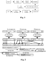
- FIG. 1 is a structural block diagram of a digital communication system according to the related art.
- the digital communication system is generally composed of a transmitting side, a channel and a receiving side, wherein the transmitting side generally includes a source, a source encoder, a channel encoder and a modulator and etc., the receiving side generally includes a demodulator, a channel decoder, a source decoder and a sink, a channel (or a storage media) exists between the transmitting side and the receiving side, and a noise source exists in the channel.
- a channel coding link (including channel coding/decoding, modulating/demodulating and etc.) is the most important technology of the whole digital communication physical layer, which determines the effectiveness and reliability of bottom layer transmission of the digital communication system.
- channel coding/decoding and modulating/demodulating parts in the channel coding link will be described in detail hereinafter.
- the object of channel coding is to resist various noises and interferences in a transmission process.
- the system can be enabled to obtain the capability of automatic error correction, so as to guarantee the reliability of the digital transmission.
- a Turbo code is one of currently-known optimal forward error correction codes, which is widely-used as a channel coding solution in data service transmission in numerous standard protocols.
- the commonly-used Turbo code includes a binary Turbo code and a double-binary tail-biting Turbo code.
- the process of rate matching is an important technology after the channel coding, the object of which is to repeat or puncture under the control of an algorithm the codeword bits after the channel coding, so as to guarantee that the data bit length after the rate matching matches the allocated physical channel resource.
- 3GPP 3 rd generation partnership project
- CBRM circular buffer rate matching
- the circular buffer rate matching algorithm is a simple algorithm, and the performance of the generated puncturing pattern is excellent.
- Such a rate matching algorithm is used in most communication systems such as the 3GPP2 standard series, the IEEE802.16e standard and the 3GPP long-term evolution (LTE for short).
- the codeword bits output by the Turbo coding are separated to obtain three data bit streams by bit separation, which includes a system bit stream, a first check bit stream and a second check bit stream.
- the above three data bit streams are respectively rearranged by a block interleaver, the processing procedure of which is usually referred to as intra-block interleaving.
- the rearranged system bit stream is placed at the start position, and then the two rearranged check bit streams are interleavingly arranged, the processing procedure of which is usually referred to as inter-block interleaving.
- N data coding bits can be selected as the output of the circular buffer rate matching according to an expected output code rate, and in the circular buffer rate matching, the N data coding bits are read from a certain designated start position in the output buffer, the process of which is referred to as bit selection.
- bit selection the process of which is referred to as bit selection.
- the bits which are selected to be used for transmission can be read from any position in the buffer. After the last bit in the circular buffer is read, the next bit data thereto is the data of the first bit position in the circular buffer. Therefore, the rate matching (puncturing or repeating) based on the circular buffer can be realized by a simple method.
- the circular buffer has further the advantage of flexibility and granularity.
- the HARQ is an important link adaptation technology in the digital communication system.
- the function of the technology is that: a receiver decodes the received HARQ data packet, wherein if the decoding is correct, an ACK signal is fed back to a transmitting side to inform the transmitting side to send a new HARQ data packet; and if the decoding is failed, a NACK signal is feedback to the transmitting side to request the transmitting side to retransmit the HARQ data packet.
- the receiving side can improve the decoding success probability and realize the high reliability requirement in the link transmission, by performing the incremental redundancy (IR for short) or the chase combination decoding on multiply-repeated data packets.
- different position in the circular buffer can be designated as the start position for reading data for each transmission of HARQ data packet.
- redundancy version RV for short
- multiple start positions for reading data in the circular buffer for the HARQ data packet are determined, and according to the value of the redundancy version, the specific start position for reading data in the circular buffer in the present HARQ data packet transmission is determined.
- a redundancy version defines a start point in a circular buffer for selecting a segment of codeword to generate a current HARQ packet. If the number of the RV is 4, the redundancy version marks four positions equally in the circular buffer in a sequence from left to right by use of 0, 1, 2 and 3. The more detailed description can be obtained by reference to the proposals and standards of virtual circular buffer rate matching of the LTE, which will not be described in detail any more.
- the HARQ subpacket identifier (SPID for short) is currently applied in the IEEE802.16e standard, and the function of the SPID is essentially the same as that of the redundancy version (RV). Both of them can be used for determining the specific position of subpacket data in the circular buffer.
- the HARQ subpacket identifier and an HARQ data packet length collectively define the start position and the length of the HARQ subpacket data in the circular buffer, so as to select a segment of codeword in the circular buffer to generate the current HARQ subpacket.
- the value range of the SPID is ⁇ 00, 01, 10, 11 ⁇ .
- the value of the SPID transmitted for the first time must be 00, and the values of the SPIDs in other retransmissions (i.e. it is not the first transmission) can be arbitrarily selected or selected in a certain order in the above SPID value range. That is to say, in multiple transmissions, a certain SPID value may be used repeatedly or may not be used.
- multiple HARQ subpackets can be generated based on the same mother code data.
- the overlapping phenomenon may occur. To improve the system performance, such overlapping phenomenon should be avoided as much as possible, and the more mother code data should be covered.
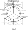
- Fig.2 is a schematic diagram illustrating the rate matching process under the IEEE802.16e standard, 1/3 code rate, and coding by the convolutional Turbo code (CTC for short) according to the related art.
- the process procedure of retransmission relates to the intra-block interleaving for S information bit, P1 check area and P2 check area.
- four retransmissions are performed, i.e.
- the length and the value of modulation orders of each HARQ subpacket are both associated with the value of the number of subchannels of the HARQ subpacket. Since the number of the subchannels of the subpacket of each transmission may be varied due to the influence of multiple factors, the modulation orders and the length of HARQ subpacket of each transmission may both be varied.
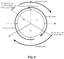
- Fig. 3 is a schematic diagram illustrating the process of the rate matching according to the related art. As shown in Fig. 3 , there are 3N EP bits codewords in the circular buffer. In This process procedure, four retransmissions are performed. This method is based on the idea of continuous transmission actually, whereas the second retransmission, the third retransmission and the fourth retransmission are continuous transmission from back to front. The non-adaptive HARQ can realize the continuous transmission, however for the adaptive HARQ, since the size of Lk is different from each other, the third retransmission and the fourth retransmission can not be continuous coincidently.
- Fig. 4 is a schematic diagram illustrating the coverage situation in the process procedure of the rate matching according to the prior and related art.
- the present invention is provided for the problem that the probability of the overlapping phenomena occurred in the process of the rate matching is high, thus, the main object of the present invention is to provide an improved rate matching solution to solver the above problem.
- a rate matching method is provided according to one aspect of the present invention.
- the rate matching method includes: coding and interleaving an information bit sequence to obtain a mother code codeword with a length N FB_Buffer ; and selecting bits from the mother code codeword to generate a hybrid automatic repeat request (HARQ) subpacket for current transmission.
- HARQ hybrid automatic repeat request
- a rate matching device is provided according to another aspect of the present invention.
- the rate matching device includes: an encoder, adapted to code the information bit sequence to generate a codeword with a length N FB_Buffer ; an interleaver, adapted to interleave the codeword generated by the encoder to obtain an interleaved mother code codeword; a circular buffer, adapted to store the interleaved mother code codeword obtained by the interleaver; and a rate matcher, adapted to select bits from the mother code codeword to generate a HARQ subpacket of current transmission.
- a rate matching device is provided according to another aspect of the present invention.
- the rate matching device includes: an encoder, adapted to code the information bit sequence to generate a codeword with a length N FB_Buffer ; a memory, adapted to store the codeword coded by the encoder and virtual circular buffer generated by an address generator; the address generator, adapted to generate corresponding address of each codeword bit of a HARQ subpacket for current transmission in the memory, interleave the codeword stored in the memory to generate the virtual circular buffer with the length N FB_Buffer , take the data of the virtual circular buffer as a mother code codeword, and continuously select from the mother code codeword the address corresponding to a codeword bit section for generating the HARQ subpacket; and a codeword bit reader, adapted to select codewords from the memory according to the address selected by the address generator to generate the HARQ subpacket for current transmission.
- a solution for decreasing the overlapping phenomena by changing the manner of selecting bits in the mother code codeword is adopted, so as to solve the problem that the probability of the overlapping phenomena occurred in the process of the rate matching is high, achieve the effect of covering the overall mother code areas as much as possible, and further increase the performance of HARQ multiple retransmission link.
- a rate matching method is provided by embodiments of the present invention, which decreases the overlapping phenomena by changing the manner of selecting bits in the mother code codeword.
- a rate matching method is provided according to an embodiment of the present invention.
- the method includes that: an information bit sequence is coded and interleaved to obtain a mother code codeword with a length N FB_Buffer , and bits are selected from the mother code codeword to generate a HARQ subpacket for current transmission, wherein the mother code codeword includes a system bit part and a check bit part.
- the start bit of the mother code codeword is regarded as the next bit of the last bit of the mother code codeword. It is supposed that a value range of a SPID of the HARQ subpacket retransmission is 0, 1, 2, 3.
- the first L bits are selected starting from a predetermined start position in the mother code codeword with the length N FB_Buffer to compose the HARQ subpacket, wherein the L is a predetermined length of the HARQ subpacket.
- the last L bits are selected from the mother code codeword with the length N FB_Buffer to compose the HARQ subpacket, wherein the L is a predetermined length of the HARQ subpacket.
- L bits are selected by taking the middle position of the mother code codeword with the length N FB_Buffer as the center position to compose the HARQ subpacket, wherein it is selected that both sides of the center position have approximately equal bit numbers as much as possible, and the L is a predetermined length of the HARQ subpacket.
- L bits are selected by taking the last bit position of the mother code codeword with the length N FB_Buffer as the center position to compose the HARQ subpacket, wherein it is selected that both sides of the center position have approximately equal bit numbers as much as possible, and the L is a predetermined length of the HARQ subpacket.
- the first L bits are selected from the mother code codeword with the length N FB_Buffer by taking the position of the first bit of a first check bit stream as the start position to compose the HARQ subpacket, wherein the L is a predetermined length of the HARQ subpacket.
- the first L bits are selected from the mother code codeword with the length N FB_Buffer by taking the position obtained by adding the position of the first bit position of a first check bit stream and L/2 bit as the start position to compose the HARQ subpacket, wherein the L is a predetermined length of the HARQ subpacket.
- the first L bits are selected by taking the middle position of the mother code codeword as the start position to compose the HARQ subpacket, wherein the L is a predetermined length of the HARQ subpacket.
- L bits are selected by taking the middle position of the mother code codeword as the end position to compose the HARQ subpacket, wherein the L is a predetermined length of the HARQ subpacket.
- L bits are selected by taking the middle position between the last bit of the mother code codeword and the first bit of a first check bit stream as the end position to compose the HARQ subpacket, wherein the L is a predetermined length of the HARQ subpacket.
- L bits are selected by taking the position of the last bit of an information bit stream of the mother code codeword as the end position to compose the HARQ subpacket, wherein the L is a predetermined length of the HARQ subpacket.
- any one of the above ten kinds of approaches for determining the start position of the HARQ subpacket can be adopted respectively according to the specific situation of the current HARQ subpacket.
- the process of grouping the information and coding and interleaving the grouped information to obtain the system bit part and the check bit part can specifically include one of the following manners.
- the grouped information is coded to obtain the system bit part and the uninterleaved check bit part, and the obtained system bit part is taken as a system bit part of the mother code codeword;
- the uninterleaved check bit part is intra-block interleaved to obtain the intra-block interleaved check bit part;
- the intra-block interleaved check bit part is performed inter-block interleaved to obtain the inter-block interleaved check bit part, and the inter-block interleaved check bit part is taken as a check bit part of the mother code codeword.
- the grouped information is coded to obtain an uninterleaved system bit part and an uninterleaved check bit part;
- the uninterleaved system bit part and the uninterleaved check bit part are intra-block interleaved to obtain the intra-block interleaved system bit part and the intra-block interleaved check bit part, and the intra-block interleaved system bit part is taken as a system bit part of the mother code codeword;
- the intra-block interleaved check bit part is inter-block interleaved to obtain the inter-block interleaved check bit part, and the inter-block interleaved check bit part is taken as a check bit part of the mother code codeword.
- the code rate of an encoder for performing the coding is 1/r
- the number of the obtained uninterleaved check bit part is r-1.
- the mode for coding the information bit sequence includes one of the following: Turbo code, tail biting Turbo code, and low density parity check code.
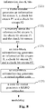
- L bits from (N FB_Buffer /2 - L/2) mod (N FB_Buffer ) to (N FB_Buffer /2+L/2-1) mod (N FB_Buffer ) are sequentially read starting from the bit at the position of (N FB_Buffer /2- L/2) mod (N FB_Buffer ) in the mother code codeword (circular buffer), i.e., the (N FB_Buffer /2-L/2)mod(N FB_Buffer )th bit, the (((N FB_Buffer /2-L/2)mod(N FB_Buffer ))+1)th bit, the (((N FB_Buffer /2-L/2)mod(N FB_Buffer ))+2)th bit, ..., the ((N FB_Buffer /2+L/2-1)mod(N FB_Buffer ))th bit.
- L bits from (N FB_Buffer -L/2) mod (N FB_Buffer ) to (N FB_Buffer +L/2-1) mod (N FB_Buffer ) are sequentially read starting from the bit at the position of the (N FB_Buffer -L/2)mod(N FB_Buffer ) in the mother code codeword (circular buffer), i.e., the (N FB_Buffer -L/2)mod(N FB_Buffer )th bit, the (((N FB_Buffer -L/2)mod(N FB_Buffer )+1)th bit, the (((N FB_Buffer -L/2)mod(N FB_Buffer ))+2)th bit, ..., the ((N FB_Buffer +L/2 -1)mod(N FB_Buffer ))th bit.
- L bits from the first bit of the first check bit stream to the bit at the position of (the first bit of the first check bit stream+L-1) mod (N FB_Buffer ) are sequentially read starting from the first bit of the first check bit stream in the mother code codeword (circular buffer), i.e., the first bit of the first check bit stream, the second bit of the first check bit stream, the third bit of the first check bit stream, ..., (the first bit of the first check bit stream+L-1) mod (N FB_Buffer ) bit.
- L bits from (the first bit of the first check bit stream+N FB_Buffer /2) to (the first bit of the first check bit stream+N FB_Buffer /2+L-1) mod (N FB_Buffer ) are sequentially read starting from the position obtained by adding the first bit position of the first check bit stream and N FB_Buffer /2 in the mother code codeword (circular buffer), i.e., the (the first bit of the first check bit stream+ NFB_Buffer /2)th bit, the ((the first bit of the first check bit stream+N FB_Buffer /2)+1)th bit, the ((the first bit of the first check bit stream+N FB_Buffer /2)+2)th bit, ..., the ((the first bit of the first check bit stream+N FB_Buffer /2+L-1) mod (N FB_Buffer ))th bit.
- L bits from (N FB_Buffer /2) mod (N FB_Buffer ) to (N FB_Buffer /2+L-1) mod (N FB_Buffer ) are sequentially read starting from the bit at the position of (N FB_Buffer_Buffer /2) mod (N FB_Buffer ) in the mother code codeword (circular buffer).
- L bits from (N FB_Buffer /2-L) mod (N FB_Buffer ) to (N FB_Buffer /2-1) mod (N FB_Buffer ) are sequentially read starting from the bit at the position of (N FB_Buffer /2-L) mod (N FB_Buffer ) in the mother code codeword (circular buffer).
- L bits from (the first bit of the first check bit stream + M*func ((N FB_Buffer -the first bit of the first check bit stream) / (2*M)) -L) mod (N FB_Buffer ) to (the first bit of the first check bit stream + M*func ((N FB_Buffer - the first bit of the first check bit stream) / (2*M)) -1) are sequentially read starting from the bit at the position of (the first bit of the first check bit stream + M*func ((N FB_Buffer - the first bit of the first check bit stream) / (2*M)) -L) mod (N FB_Buffer ) in the mother code codeword (circular buffer), wherein the M represents a modulation mode of the current HARQ subpacket, the func(x) represents rounding upward, rounding downward or rounding off for x.
- L bits from (the first bit of a first check bit stream-L) mod (N FB_Buffer ) to (the first bit of the first check bit stream-1) are sequentially read starting from the bit at the position of the (the first bit of the first check bit stream-L) mod (N FB_Buffer ) in the mother code codeword (circular buffer).
- the mod operation is required in the method of the present embodiment.
- the whole mother code data can be covered to the largest extent, and at the same time the overlapping phenomena occurring in the related art can be avoided to the largest extent, thereby enhancing the performance of the HARQ multiple retransmission link.
- a process procedure of a rate matching method used in a first rate matching device of an embodiment of the present invention will be described in detail by taking 1/3 code rate as the example (but it is not limited to 1/3 code rate) hereinafter.
- the rate matching method includes: an information bit sequence is coded and interleaved to obtain a mother code codeword with a length N FB_Buffer , wherein the mother code codeword includes a system bit part and a check bit part. It is supposed that a value range of a SPID of the HARQ subpacket retransmission is 0, 1, 2, 3. Ten kinds of approaches for determining the start position of the HARQ subpacket are given hereinafter.
- the first L bits are selected starting from a predetermined start position in the mother code codeword with the length N FB_Buffer to compose the HARQ subpacket, wherein the L is a predetermined length of the HARQ subpacket.
- the last L bits are selected from the mother code codeword with the length N FB_Buffer to compose the HARQ subpacket, wherein the L is a predetermined length of the HARQ subpacket.
- L bits are selected by taking the middle position of the mother code codeword with the length N FB_Buffer as the center position to compose the HARQ subpacket, wherein it is selected that both sides of the center position have approximately equal bit numbers as much as possible, and the L is a predetermined length of the HARQ subpacket.
- L bits are selected by taking the last bit position of the mother code codeword with the length N FB_Buffer as the center position to compose the HARQ subpacket, wherein it is selected that both sides of the center position have approximately equal bit numbers as much as possible, and the L is a predetermined length of the HARQ subpacket.
- the first L bits are selected from the mother code codeword with the length N FB_Buffer by taking the position of the first bit of a first check bit stream as the start position to compose the HARQ subpacket, wherein the L is a predetermined length of the HARQ subpacket.
- the first L bits are selected from the mother code codeword with the length N FB_Buffer by taking the position obtained by adding the position of the first bit position of a first check bit stream and L/2 bit as the start position to compose the HARQ subpacket, wherein the L is a predetermined length of the HARQ subpacket.
- the first L bits are selected by taking the middle position of the mother code codeword as the start position to compose the HARQ subpacket, wherein the L is a predetermined length of the HARQ subpacket.
- L bits are selected by taking the middle position of the mother code codeword as the end position to compose the HARQ subpacket, wherein the L is a predetermined length of the HARQ subpacket.
- L bits are selected by taking the middle position between the last bit of the mother code codeword and the first bit of a first check bit stream as the end position to compose the HARQ subpacket, wherein the L is a predetermined length of the HARQ subpacket.
- L bits are selected by taking the position of the last bit of an information bit stream of the mother code codeword as the end position to compose the HARQ subpacket, wherein the L is a predetermined length of the HARQ subpacket.
- any one of the above ten kinds of approaches for determining the start position of the HARQ subpacket can be adopted respectively according to the specific situation of the current HARQ subpacket.
- the first rate matching mode is of respectively selecting the first, the second, the third, the fourth approach for determining the start position of the subpacket when the value of the SPID is 0, 1, 2, 3
- the second rate matching mode is of respectively selecting the first, the second, the fifth, the sixth approach for determining the start position of the subpacket when the value of the SPID is 0, 1, 2, 3
- the third rate matching mode is of respectively selecting the first, the second, the seventh, the eighth approach for determining the start position of the subpacket when the value of the SPID is 0, 1, 2, 3
- the fourth rate matching mode is of respectively selecting the first, the second, the ninth, the tenth approach for determining the start position of the subpacket when the value of the SPID is 0, 1, 2, 3.
- any one of the above ten kinds of approaches for determining the start position of the HARQ subpackets can be selected respectively according to the situation of the current HARQ subpackets when the value of the SPID is 0, 1, 2, 3 in the embodiments of the present invention. That is to say, the first, the third, the fourth, the sixth approach for determining the start position of the subpacket can be respectively selected when the value of the SPID is 0, 1, 2, 3, or the first, the second, the fifth, the eighth approach for determining the start position of the subpacket can also be respectively selected when the value of the SPID is 0, 1, 2, 3.
- Fig.7 is a process flowchart of a first rate matching device according to an embodiment 1 of the present invention. As shown in Fig.7 , in the case of 1/3 code rate, the process procedure of the first rate matching mode adopted by the first rate matching device includes the following Steps 111-114.
- Step 111 information with a length K is transmitted to a Turbo encoder with 1/3 code rate, to generate a system bit stream S, a first check bit stream P1 and a second check bit stream P2.
- Step 112 the codewords (i.e., the system bit stream S, the first check bit stream P1 and the second check bit stream P2) coded by the Turbo encoder are intra-block interleaved respectively by a sub-interleaver, to generate a new system bit stream S, a new first check bit stream P1 and a new second check bit stream P2.
- Step 113 the system bits are placed in the front of a circular buffer, the first parity check bit stream and the second parity check bit stream are placed in interlacement mode behind the system bit stream through an inter-block interleaver, and finally the circular buffer is formed, wherein the stored data is the above mother code, and the length of the mother code is N FB_Buffer codeword bits, wherein since the mother code codeword is placed in the circular buffer, the next bit of the last bit in the mother code codeword is the first bit position of the mother code; and the index of the mother code starts from 0.
- Step 114 codeword bits with required length of each HARQ transmission are sequentially read from the mother code to form a HARQ subpacket.
- the reading position of each HARQ subpacket can be determined by the following process.
- the length of a HARQ subpacket is determined in advance, when the HARQ subpacket transmission is performed each time.
- the data content of the HARQ subpacket to be transmitted each time is circularly read from the mother code.
- the method for reading the HARQ subpacket data of the first rate matching mode is as follows.
- the value of the SPID is 0 when the HARQ subpacket is transmitted for the first time, namely, L1 bits are sequentially read starting from the 0th bit in the circular buffer, i.e. from the 0th bit, the 1st bit, the 2nd bit up to the (L1-1)th bit, wherein the L1 is the length of the first subpacket.
- the value of the SPID is 1 when the HARQ subpacket is transmitted for the second time, namely, L2 bits are sequentially read starting from the bit at the position of the (N FB_Buffer -L2) in the circular buffer, i.e. from the (N FB_Buffer -L2)th bit, the (N FB_Buffer -L2+1)th bit, the (N FB_Buffer -L2+2)th bit up to the (N FB_Buffer -1)th bit, wherein the L2 is the length of the second subpacket.
- the value of the SPID is 2 when the HARQ subpacket is transmitted for the third time, namely, L3 bits are sequentially read starting from the bit at the position of the (N FB_Buffer /2-L3/2)mod(N FB_Buffer ) in the circular buffer, i.e.
- the value of the SPID is 3 when the HARQ subpacket is transmitted for the fourth time, namely, L4 bits are sequentially read starting from the bit at the position of the (N FB_Buffer -L4/2)mod(N FB_Buffer ) in the circular buffer, i.e.
- the process of the first rate matching mode is as follows.
- the information bit stream ⁇ a0, a1, ..., a4799 ⁇ is transmitted into a CTC encoder, to form an information bit stream S ⁇ a0, a1, ..., a4799 ⁇ , a check bit stream P1 ⁇ p 1 0, p 1 1, ..., p 1 4799 ⁇ , a check bit stream P2 ⁇ p 2 0, p 2 1, ..., p 2 4799 ⁇ .
- check bit stream P1 and check bit stream P2 pass through an intra-block sub-interleaver, a new system bit stream S ⁇ a0', a1', ..., a4799' ⁇ , a new check bit stream P1 ⁇ p 1 0', p 1 1', ..., p 1 4799' ⁇ and P2 ⁇ p 2 0', p 2 1', ..., p 2 4799' ⁇ are formed.
- the new check bit stream P1 and the new check bit stream P2 pass through the inter-block sub-interleaver, a mother code codeword is formed and is stored in the circular buffer, i.e. ⁇ m0, m1, ..., m14399 ⁇ .
- the N FB_Buffer is 14400.
- Lk (k is 1, 2, 3, 4) codeword bits required by each HARQ transmission are sequentially read from the circular buffer to form a HARQ subpacket.
- the rate matching is performed according to the first rate matching mode of the embodiment of the present invention.
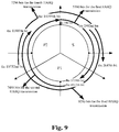
- Fig. 9 is an overlapping circular schematic diagram of the first rate matching mode according to the embodiment 1 of the present invention.
- the read HARQ subpackets are respectively as follows: the first HARQ subpacket is ⁇ m0, m1, ..., m5759 ⁇ , the second HARQ subpacket is ⁇ m6912, m6913, ..., m14399 ⁇ , the third HARQ subpacket is ⁇ m2592, m2593, ..., m11807 ⁇ , the fourth HARQ subpacket is ⁇ m10752, m10753, ..., m14399, m0, m1, ..., m3647 ⁇ .
- the mother code codeword ⁇ m5760, m5761, ..., m6911 ⁇ has totally 1152 bits not covered after the second HARQ subpacket transmission, the overlapping phenomenon does not exist.
- the mother code data which is not transmitted during the first transmission and the second transmission is transmitted to the largest extent, so as to cover the mother code data to the largest extent.
- the mother code codeword bit can be better covered in the same condition, and the overlapping phenomenon is reduced as much as possible, thereby increasing the performance of the HARQ link.
- the first, the second, the fifth, and the sixth approaches for determining the start position of the subpacket are respectively selected when the value of the SPID is 0, 1, 2, 3.
- the process procedure of the rate matching method according to the embodiment of the present invention is as shown in Fig.7 , which is not described any more herein.
- the difference of the second rate matching mode is that, in the following embodiment, the first, the second, the fifth, the sixth approaches for determining the start position of the subpacket are respectively selected when the value of the SPID is 0, 1, 2, 3.
- the method for reading the HARQ subpacket data is as follows.
- the value of the SPID is 0 when the HARQ subpacket is transmitted for the first time, namely, L1 bits are sequentially read starting from the bit at the position of the 0 in the circular buffer, i.e. from the 0th bit, the 1st bit, the 2nd bit up to the (L1-1)th bit, wherein the L1 is the length of the first subpacket.
- the value of the SPID is 1 when the HARQ subpacket is transmitted for the second time, namely, L2 bits are sequentially read starting from the bit at the position of the (N FB_Buffer -L2) in the circular buffer, i.e. from the (N FB_Buffer -L2)th bit, the (N FB_Buffer -L2+1)th bit, the (N FB_Buffer -L2+2)th bit up to the (N FB_Buffer -1)th bit, wherein the L2 is the length of the second subpacket.
- the value of the SPID is 2 when the HARQ subpacket is transmitted for the third time, namely, L3 bits are sequentially read starting from the first bit in the circular buffer, i.e. from the first bit of the first check bit stream, the second bit of the first check bit stream, the third bit of the first check bit stream up to the (the first bit of the first check stream +L3-1)mod(N FB_Buffer )th bit of the first check bit stream, wherein the L3 is the length of the third subpacket.
- the value of the SPID is 3 when the HARQ subpacket is transmitted for the fourth time, namely, L4 bits are sequentially read starting from the bit at the position of (the first bit of a first check bit stream +N FB_Buffer /2) in the circular buffer, i.e.
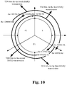
- Fig.10 is an overlapping circular schematic diagram of the second rate matching mode according to the embodiment 1 of the present invention.
- the read HARQ subpackets are respectively as follows: the first HARQ subpacket is ⁇ m0, m1, ..., m5759 ⁇ , the second HARQ subpacket is ⁇ m6912, m6913, ..., m14399 ⁇ , the third HARQ subpacket is ⁇ m4800, m4801, ..., m14015 ⁇ , and the fourth HARQ subpacket is ⁇ m12000, m12001, ..., m14399, m0, m1, ..., m4895 ⁇ .
- the mother code codeword ⁇ m5760, m5761, ..., m6911 ⁇ has totally 1152 bits not covered after the second HARQ subpacket transmission, the overlapping phenomenon does not exist,.
- the mother code data which is not transmitted during the first transmission and the second transmission is transmitted to the largest extent, so as to cover the mother code data to the largest extent.
- the mother code codeword bit can also be better covered in the same condition, and the overlapping phenomenon is reduced as much as possible, thereby increasing the performance of the HARQ link.
- the first, the second, the seventh, and the eighth approaches for determining the start position of the subpacket are respectively selected when the value of the SPID is 0, 1, 2, 3.
- the process procedure of the rate matching method according to the embodiment of the present invention is as shown in Fig.7 , which is not described any more herein.
- the difference of the third rate matching mode is that, in the following embodiment, the first, the second, the seventh, and the eighth approaches for determining the start position of the subpacket are respectively selected when the value of the SPID is 0, 1, 2, 3.
- the method for reading the HARQ subpacket data is as follows.
- the value of the SPID is 0 when the HARQ subpacket is transmitted for the first time, namely, L1 bits are sequentially read starting from the bit at the position of the 0 in the circular buffer, i.e. from the 0th bit, the 1st bit, the 2nd bit up to the (L1-1)th bit, wherein the L1 is the length of the first subpacket.
- the value of the SPID is 1 when the HARQ subpacket is transmitted for the second time, namely, L2 bits are sequentially read starting from the bit at the position of the (N FB_Buffer -L2) in the circular buffer, i.e. from the (N FB_Buffer -L2)th bit, the (N FB_Buffer -L2+1)th bit, the (N FB_Buffer -L2+2)th bit up to the (N FB_Buffer -1)th bit, wherein the L2 is the length of the second subpacket.
- the value of the SPID is 2 when the HARQ subpacket is transmitted for the third time, namely, L bits are sequentially read starting from the bit at the position of the (N FB_Buffer /2) mod (N FB_Buffer ) in the circular buffer, i.e. from the (N FB_Buffer /2) mod (N FB_Buffer ) th bit to the (N FB_Buffer /2+L-1) mod (N FB_Buffer ) th bit, wherein the L3 is the length of the third subpacket.
- the value of the SPID is 3 when the HARQ subpacket is transmitted for the fourth time, namely, L bits are sequentially read starting from the bit at the position of the (N FB_Buffer /2-L) mod (N FB_Buffer ) in the circular buffer, i.e. from the (N FB_Buffer /2-L) mod (N FB_Buffer ) th bit to the (N FB_Buffer /2-1) mod (N FB_Buffer ) th bit, wherein the L4 is the length of the fourth subpacket.
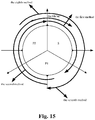
- Fig. 14 is an overlapping circular schematic diagram of the third rate matching mode according to the embodiment 1 of the present invention.
- the read HARQ subpackets are respectively as follows: the first HARQ subpacket is ⁇ m0, m1, ..., m5759 ⁇ , the second HARQ subpacket is ⁇ m6912, m6913, ..., m14399 ⁇ , the third HARQ subpacket is ⁇ m7200, m7201, ..., m12015 ⁇ , and the fourth HARQ subpacket is ⁇ m14304, m14305, ..., m14399, m0, m1, ..., m7199 ⁇ .
- the mother code codeword bit can also be better covered in the same condition, and the overlapping phenomenon is reduced as much as possible, thereby increasing the performance of the HARQ link.
- the first, the second, the ninth, the tenth approaches for determining the start position of the subpacket are respectively selected when the value of the SPID is 0, 1, 2, 3.
- the process procedure of the rate matching method according to the embodiment of the present invention is as shown in Fig.7 , which is not described any more herein.
- the difference of the fourth rate matching mode is that, in the following embodiment, the first, the second, the ninth, the tenth approaches for determining the start position of the subpacket are respectively selected when the value of the SPID is 0, 1, 2, 3.
- the method for reading the HARQ subpacket data is as follows.
- the value of the SPID is 0 when the HARQ subpacket is transmitted for the first time, namely, L1 bits are sequentially read starting from the bit at the position of the 0 in the circular buffer, i.e. from the 0th bit, the 1st bit, the 2nd bit up to the (L1-1)th bit, wherein the L1 is the length of the first subpacket.
- the value of the SPID is 1 when the HARQ subpacket is transmitted for the second time, namely, L2 bits are sequentially read starting from the bit at the position of the (N FB_Buffer -L2) in the circular buffer, i.e. from the (N FB Buffer -L2)th bit, the (N FB_Buffer -L2+1)th bit, the (N FB_Buffer -L2+2)th bit up to the (N FB_Buffer -1)th bit, wherein the L2 is the length of the second subpacket.
- the value of the SPID is 2 when the HARQ subpacket is transmitted for the third time, namely, L3 bits are sequentially read starting from the bit at the position of the ((the first bit of the first check bit stream +M*func ((N FB_Buffer -the first bit of the first check bit stream)/(2*M))-L3)mod(N FB_Buffer )) in the circular buffer, i.e.
- the value of the SPID is 3 when the HARQ subpacket is transmitted for the fourth time, namely, L4 bits are sequentially read starting from the bit at the position of the ((the first bit of the first check bit stream-L4) mod (N FB_Buffer )) in the circular buffer, i.e. from the ((the first bit of the first check bit stream-L4) mod (N FB_Buffer ))th bit, the ((the first bit of the first check bit stream-L4)mod(N FB_Buffer )+1)th bit, the ((the first bit of the first check bit stream-L4)mod(N FB_Buffer )+2)th bit up to the (the first bit of the first check stream-1)th bit.
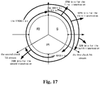
- Fig. 17 is an overlapping circular schematic diagram of the fourth rate matching mode according to the embodiment 1 of the present invention.
- the read HARQ subpackets are respectively as follows: the first HARQ subpacket is ⁇ m0, m1, ..., m5759 ⁇ , the second HARQ subpacket is ⁇ m6912, m6913, ..., m14399 ⁇ , the third HARQ subpacket is ⁇ m12384, m12385, ..., m9599 ⁇ , and the fourth HARQ subpacket is ⁇ m11904, m11905, ..., m14399, m0, m1, ..., m4799 ⁇ .
- the mother code codeword bit can also be better covered in the same condition, and the overlapping phenomenon is reduced as much as possible, thereby increasing the performance of the HARQ link.
- Fig.8 is a process flowchart of the second rate matching device according to an embodiment 2 of the present invention. As shown in Fig.8 , in the case of 1/3 code rate, the process procedure of the first rate matching mode adopted by the second rate matching device includes the following Steps 121-125.
- Step 121 information with a length K is transmitted to a Turbo encoder with 1/3 code rate, to generate a system bit stream S, a first check bit stream P1 and a second check bit stream P2.
- Step 122 the codewords (i.e., the system bit stream S, the first check bit stream P1 and the second check bit stream P2) coded by the Turbo encoder are stored in a memory.
- Step 123 the codewords (i.e. the system bit stream S, the first check bit stream P1 and the second check bit stream P2) stored in the memory are intra-block interleaved respectively through an address generator, to generate a new system bit stream S, a new first check bit stream P1 and a new second check bit stream P2, so as to form a virtual circular buffer.
- Step 124 the new system bit stream S is placed in the front of the virtual circular buffer, the first parity check bit stream P1 and the second parity check bit stream P2 are inter-block interleaved through an address generator, i.e. the first parity check bit stream P1 and the second parity check bit stream P2 are stored interlacedly behind the system bit stream in the virtual circular buffer, and finally the virtual circular buffer is formed, wherein the stored data is the virtual mother code, and the length of the mother code is N FB_Buffer codeword bits.
- the virtual mother code codeword is placed in the virtual circular buffer, the next bit of the last bit in the mother code codeword is the 0th bit of the mother code; and the index of the mother code starts from 0.
- Step 125 codeword bits are selected from the memory by a codeword bit reader according to an address generated by the address generator, to generate the HARQ subpacket for the current transmission. Namely, the codeword bits with the required length of each HARQ transmission are sequentially read from the virtual mother code, to form a HARQ subpacket.
- the position of each reading of the HARQ subpacket can be determined by the following process.
- the length of a HARQ subpacket is determined in advance, when the HARQ subpacket transmission is performed each time.
- the data content of the HARQ subpacket to be transmitted each time is circularly read from the virtual mother code.
- the method for reading the HARQ subpacket data in the first rate matching method is learned by referring to the embodiment 1, which is not described any more herein.
- the process of the first rate matching mode is as follows.
- the information bit stream ⁇ a0, a1, ..., a4799 ⁇ is transmitted into a CTC encoder, to form an information bit stream S ⁇ a0, a1, ..., a4799 ⁇ , a check bit stream P1 ⁇ p 1 0, p 1 1, ..., p 1 4799 ⁇ , a check bit stream P2 ⁇ p 2 0, p 2 1, ..., p 2 4799 ⁇ .
- a new system bit stream S ⁇ a0' a1', ..., a4799' ⁇
- a new check bit stream P1 ⁇ p 1 0', p 1 1', ..., p 1 4799' ⁇ and P2 ⁇ p 2 0' p 2 1', ..., p 2 4799' ⁇ are formed.
- a virtual mother code codeword is formed and is stored in the virtual circular buffer, i.e. ⁇ m0, m1, ..., m14399 ⁇ .
- Lk (k is 1, 2, 3, 4) codeword bits required by each HARQ transmission are sequentially read from the virtual circular buffer to form a HARQ subpacket.
- the rate matching is performed according to the first rate matching mode of the embodiment of the present invention, which is as shown in Fig.9 , wherein the first HARQ subpacket is ⁇ m0, m1, ..., m5759 ⁇ , the second HARQ subpacket is ⁇ m6912, m6913, ..., m14399 ⁇ , the third HARQ subpacket is ⁇ m2592, m2593, ..., m11807 ⁇ , the fourth HARQ subpacket is ⁇ m10752, m10753, ..., m14399, m0, m1, ..., m3647 ⁇ .
- the second rate matching device of the embodiment of the present invention is also applied to the second, the third, and the fourth rate matching modes, the difference of which is that, the second, the third and the fourth rate matching modes are respectively used when reading the HARQ subpacket data.
- the process procedure is also as shown in Fig.8 , which is not described any more herein.
- the first rate matching mode is of respectively selecting the first, the second, the third, the fourth approach for determining the start position of the subpacket when the value of the SPID is 0, 1, 2, 3
- the second rate matching mode is of respectively selecting the first, the second, the fifth, the sixth approach for determining the start position of the subpacket when the value of the SPID is 0, 1, 2, 3
- the third rate matching mode is of respectively selecting the first, the second, the seventh, the eighth approach for determining the start position of the subpacket when the value of the SPID is 0, 1, 2, 3
- the fourth rate matching mode is of respectively selecting the first, the second, the ninth, the tenth approach for determining the start position of the subpacket when the value of the SPID is 0, 1, 2, 3, those skilled in the art should understand that, in the adaptive HARQ retransmission mechanism, any one of the above ten kinds of approaches for determining the start position of the HARQ retransmission mechanism, any one of the above ten kinds of approaches for determining the start position of the
- the first, the third, the fourth, the sixth approach for determining the start position of the subpacket can be respectively selected when the value of the SPID is 0, 1,2, 3, or the first, the second, the fifth, the eighth approach for determining the start position of the subpacket can also be respectively selected when the value of the SPID is 0, 1,2, 3.
- a rate matching device is provided.
- Fig.11 is a structural block diagram of the rate matching device according to a device embodiment 1 of the present invention. As shown in Fig.11 , the rate matching device includes: an encoder 12, an interleaver 14, a circular buffer 16, and a rate matcher 18. The above structure will be described hereinafter.
- the encoder 12 is adapted to code a grouped information to generate a codeword with a length N FB_Buffer ;
- the interleaver 14 connected to the encoder 12 is adapted to interleave the above codeword sequence with the length N FB_Buffer to obtain an interleaved mother code codeword;
- the circular buffer 16 connected to the interleaver 14 is adapted to store the interleaved mother code codeword sequence;
- the rate matcher 18 connected to the circular buffer 16 is adapted to select codeword bits from the mother code codeword to generate a HARQ subpacket for current transmission, wherein it is supposed that the value range of the SPID is 0, 1,2,3.
- the rate matcher 18 is adapted to select bits from the mother code codeword to generate the HARQ subpacket for the current transmission.
- the rate matcher 18 includes: a first rate matcher 182 which is adapted to select the first L bits starting from a predetermined start position in the mother code codeword with the length N FB_Buffer to compose a HARQ subpacket, wherein the L is a predetermined length of the HARQ subpacket; a second rate matcher 184 which is adapted to select the last L bits from the mother code codeword with the length N FB_Buffer to compose a HARQ subpacket, wherein the L is a predetermined length of the HARQ subpacket; a third rate matcher 186 which is adapted to select L bits by taking the middle position of the mother code codeword with the length N FB_Buffer as the center position to compose a HARQ subpacket, wherein it is selected that both sides of the center position have equal bit numbers as much as possible, and
- Fig.12 is a specific structural block diagram of the rate matching device according to the device embodiment 1 of the present invention.
- the above interleaver 14 includes an intra-block interleaver 22 and an inter-block interleaver 24. The above structure will be described hereinafter.
- the intra-block interleaver 22 is adapted to group and intra-block interleave the coded information, to obtain an intra-block interleaved check bit part or further obtain an intra-block interleaved system bit part.
- the inter-block interleaver 24 is connected to the intra-block interleaver 22, and is adapted to inter-block interleave the intra-block interleaved check bit part to obtain an inter-block interleaved check bit part.
- the above circular buffer 16 is adapted to store the intra-block interleaved system bit part or the uninterleaved system bit part into the circular buffer 16 at the start position, as a system bit part of the mother code codeword.
- the circular buffer 16 is further adapted to store the inter-block interleaved check bit part into the circular buffer 16 at the position behind the system bit part.
- any one of the first rate matcher 182, the second rate matcher 184, the third rate matcher 186, the fourth rate matcher 188, the fifth rate matcher 190, the sixth rate matcher 192, the seventh rate matcher 194, the eighth rate matcher 196, the ninth rate matcher 198, and the tenth rate matcher 200 can be used according to the situation of the current HARQ subpacket.
- L bits are sequentially read starting from the bit at the position of the (N FB_Buffer /2- L/2) mod (N FB_Buffer ) in the mother code codeword (circular buffer), i.e., the (N FB_Buffer /2-L/2) mod (N FB_Buffer )th bit, the (((N FB_Buffer /2-L/2) mod (N FB_Buffer ))+1)th bit, the (((N FB_Buffer /2-L/2) mod (N FB_Buffer ))+2)th bit, ...., the (N FB_Buffer /2+L/2-1) mod (N FB_Buffer )th bit.
- L bits are sequentially read starting from the bit at the position of the (N FB_Buffer -L/2)mod(N FB_Buffer ) in the mother code codeword (circular buffer), i.e., the (N FB_Buffer -L/2) mod (N FB_Buffer )th bit, the (((N FB_Buffer -L/2) mod (N FB_Buffer ))+1)th bit, the (((N FB_Buffer -L/2) mod (N FB_Buffer ))+2)th bit, ..., the (N FB_Buffer +L/2-1) mod (N FB_Buffer )th bit.
- L bits (the first bit of the first check bit stream to (the first bit of the first check bit stream+L-1) mod (N FB_Buffer ) bit) are sequentially read starting from the first bit of the first check bit stream in the mother code codeword (circular buffer), i.e., the first bit of the first check bit stream, the second bit of the first check bit stream, the third bit of the first check bit stream, ..., the (the first bit of the first check bit stream+L-1) mod (N FB_Buffer )th bit.
- L bits (the bit at the position obtained by adding the first bit of the first check bit stream and N FB_Buffer /2 to the bit at the position of (the first bit of the first check bit stream+N FB_Buffer /2+L-1) mod (N FB_Buffer ), are sequentially read starting from the position obtained by adding the first bit position of the first check bit stream and N FB_Buffer /2 in the mother code codeword (circular buffer), i.e., (the first bit of the first check bit stream+N FB_Buffer /2)th bit, ((the first bit of the first check bit stream+N FB_Buffer /2)+1)th bit, ((the first bit of the first check bit stream+N FB_Buffer /2)+2)th bit, ..., (the first bit of the first check bit stream+N FB_Buffer /2+L-1) mod (N FB_Buffer )th bit.
- L bits (the bit at the position of the (N FB_Buffer /2) mod (N FB_Buffer ) to the bit at the position of the (N FB_Buffer /2+L-1) mod (N FB_Buffer )) are sequentially read starting from the bit at the position of the (N FB_Buffer /2) mod (N FB_Buffer ) in the mother code codeword (circular buffer).
- L bits (the bit at the position of the (N FB_Buffer /2-L) mod (N FB_Buffer ) to the bit at the position of the (N FB_Buffer /2-1 ) mod (N FB_Buffer ) are sequentially read starting from the bit at the position of the (N FB_Buffer /2-L) mod (N FB_Buffer ) in the mother code codeword (circular buffer).
- L bits (the bit at the position of (the first bit of the first check bit stream + M*func ((N FB_Buffer -the first bit of the first check bit stream) / (2*M)) -L) mod (N FB_Buffer )) to the bit at the position of (the first bit of the first check bit stream + M*func ((N FB_Buffer -the first bit of the first check bit stream) / (2*M)) -1), are sequentially read starting from the bit at the position of (the first bit of the first check bit stream + M*func ((N FB_Buffer -the first bit of the first check bit stream) / (2*M)) -L) mod (N FB_Buffer ) in the mother code codeword (circular buffer), wherein the M represents a modulation mode of the current HARQ subpacket, and the func(x) represents rounding upward, rounding downward or rounding off for x.
- L bits (the bit at the position of (the first bit of the first check bit stream-L) mod (N FB_Buffer ) to the bit at the position of (the first bit of the first check bit stream-1) are sequentially read starting from the bit at the position of (the first bit of the first check bit stream-L) mod (N FB_Buffer ) in the mother code codeword (circular buffer).
- the mod operation is required in the method.
- the device of the present embodiment is applicable to the first, the second, the third and the fourth rate matching modes provided by the present invention, the difference of which is only that: the first rate matching mode is of respectively selecting the first rate matcher, the second rate matcher, the third rate matcher, and the fourth rate matcher when the value of the SPID is 0, 1, 2, 3; the second rate matching mode is of respectively selecting the first rate matcher, the second rate matcher, the fifth rate matcher, and the sixth rate matcher when the value of the SPID is 0, 1, 2, 3; the third rate matching mode is of respectively selecting the first rate matcher, the second rate matcher, the seventh rate matcher, and the eighth rate matcher when the value of the SPID is 0, 1, 2, 3; the fourth rate matching mode is of respectively selecting the first rate matcher, the second rate matcher, the ninth rate matcher, and the tenth rate matcher when the value of the SPID is 0, 1, 2, 3, which is not described any more herein.
- a second rate matching device is provided.
- Fig.13 is a structural block diagram of the rate matching device according to the device embodiment 2 of the present invention. As shown in Fig. 13 , the device includes: an encoder 32, a memory 34, an address generator 36, and a codeword bit reader 38. The above structure will be described hereinafter.
- the encoder 32 is adapted to code a grouped information to generate a codeword with a length N FB_Buffer .
- the memory 34 is connected to the encoder 32, and is adapted to store the coded codeword.
- the address generator 36 is connected to the memory, and is adapted to generate corresponding address of each codeword bit of a current HARQ subpacket in the memory, and adapted to interleave the codeword stored in the memory to generate a virtual circular buffer with the length N FB_Buffer and store it in the memory, with the data of the virtual circular buffer as a mother code codeword, and continuously select from the mother code codeword the address corresponding to a codeword bit section for generating the current HARQ subpacket, wherein it is supposed that the value range of the SPID is 0, 1, 2, 3.
- the above address generator 36 includes: a first address generator 362 which is adapted to select the first L bits starting from a predetermined start position in the mother code codeword with the length N FB_Buffer to compose a HARQ subpacket, wherein the L is a predetermined length of the HARQ subpacket; a second address generator 364 which is adapted to select the last L bits from the mother code codeword with the length N FB_Buffer to compose a HARQ subpacket, wherein the L is a predetermined length of the HARQ subpacket; a third address generator 366 which is adapted to select L bits by taking the middle position of the mother code codeword as the center position to compose a HARQ subpacket, wherein it is selected that both sides of the center position have approximately equal bit numbers, and the L is a predetermined length of the HARQ subpacket; a fourth address generator 368 which is adapted to select L bits by taking the last bit position of the mother code codeword as the center position to
- any one of the first address generator 362, the second address generator 364, the third address generator 366, the fourth address generator 368, the fifth address generator 370, the sixth address generator 372, the seventh address generator 374, the eighth address generator 376, the ninth address generator 378, and the tenth address generator 380 can be used according to the situation of the current HARQ subpacket.
- L bits are sequentially read starting from the bit at the position of the (N FB_Buffer /2-L/2)mod(N FB _Buffer ) in the mother code codeword (circular buffer), i.e., the (N FB_Buffer /2-L/2) mod (N FB_Buffer )th bit, the (((N FB_Buffer /2-L/2) mod (N FB_Buffer ))+1)th bit, the (((N FB_Buffer /2-L/2) mod (N FB_Buffer ))+2)th bit, ...., the (N FB_Buffer /2+L/2-1) mod (N FB_Buffer )th bit.
- L bits are sequentially read starting from the bit at the position of the (N FB_Buffer -L/2)mod(N FB_Buffer ) in the mother code codeword (circular buffer), i.e., the (N FB_Buffer -L/2) mod (N FB_Buffer )th bit, the (((N FB_Buffer -L/2) mod (N FB_Buffer ))+1)th bit, the (((N FB_Buffer -L/2) mod (N FB_Buffer ))+2)th bit, ..., the (N FB_Buffer +L/2-1) mod (N FB_Buffer )th bit.
- L bits (the first bit of the first check bit stream to the bit at the position of (the first bit of the first check bit stream+L-1) mod (N FB_Buffer )) are sequentially read starting from the first bit of the first check bit stream in the mother code codeword (the virtual circular buffer), i.e., the first bit of the first check bit stream, the second bit of the first check bit stream, the third bit of the first check bit stream, ..., the bit at the position of (the first bit of the first check bit stream+L-1) mod (N FB_Buffer ).
- L bits (the bit at the position of (the first bit of the first check bit stream+N FB_Buffer /2) to the bit at the position of (the first bit of the first check bit stream+N FB_Buffer /2+L-1) mod (N FB_Buffer )) are sequentially read starting from the bit at the position of (the first bit of the first check bit stream+N FB_Buffer /2) in the mother code codeword (the virtual circular buffer), i.e., the bit at the position of (the first bit of the first check bit stream+N FB_Buffer /2), the bit at the position of ((the first bit of the first check bit stream+N FB_Buffer /2)+1), the bit at the position of ((the first bit of the first check bit stream+N FB_Buffer /2)+2), ..., the bit at the position of (the first bit of the first check bit stream+N FB_Buffer /2+L-1) mod (N FB_Buffer ).
- L bits (the bit at the position of (N FB_Buffer /2) mod (N FB_Buffer ) to the bit at the position of (N FB_Buffer /2+L-1) mod (N FB_Buffer )) are sequentially read starting from the bit at the position of (N FB_Buffer /2) mod (N FB_Buffer ) in the mother code codeword (the virtual circular buffer).
- L bits (the bit at the position of (N FB_Buffer /2-L) mod (N FB_Buffer ) to the bit at the position of (N FB_Buffer /2-1) mod (N FB_Buffer )) are sequentially read starting from the bit at the position of (N FB_Buffer /2-L) mod (N FB_Buffer )in the mother code codeword (the virtual circular buffer).
- L bits (the bit at the position of (the first bit of the first check bit stream + M*func ((N FB_Buffer -the first bit of the first check bit stream) / (2*M)) -L) mod (N FB_Buffer ) to the bit at the position of (the first bit of the first check bit stream + M*func ((N FB_Buffer -the first bit of the first check bit stream) / (2*M))-1)) are sequentially read starting from the bit at the position of (the first bit of the first check bit stream + M*func ((N FB_Buffer -the first bit of the first check bit stream) / (2*M)) -L) mod (N FB_Buffer ) in the mother code codeword (the virtual circular buffer), wherein the M represents a modulation mode of the current HARQ subpacket, the func(x) represents rounding upward, rounding downward or rounding off for x.
- L bits (the bit at the position of (N FB_Buffer /2-L) mod (N FB_Buffer ) to the bit at the position of (N FB_Buffer /2-1) mod (N FB_Buffer )) are sequentially read starting from the bit at the position of (N FB_Buffer /2-L) mod (N FB_Buffer )in the mother code codeword (the virtual circular buffer).
- the mod operation is required in the present embodiment.
- the device of the present embodiment is also applicable to the first, the second, the third and the fourth rate matching modes provided by the embodiments of the present invention, the difference of which is only that: the first rate matching mode is of respectively selecting the first address generator, the second address generator, the third address generator, and the fourth address generator when the value of the SPID is 0, 1, 2, 3; the second rate matching mode is of respectively selecting the first address generator, the second address generator, the fifth address generator, and the sixth address generator when the value of the SPID is 0, 1, 2, 3; the third rate matching mode is of respectively selecting the first address generator, the second address generator, the seventh address generator, and the eighth address generator when the value of the SPID is 0, 1, 2, 3; and the fourth rate matching mode is of respectively selecting the first address generator, the second address generator, the ninth address generator, and the tenth address generator when the value of the SPID is 0, 1, 2, 3, which is not described any more herein.
- the implementation of the present invention does not modify the system architecture and the current process flow, which is easy for implementation and is convenient for promotion in the technical fields, and has strong industrial applicability.
- each of the above modules or steps of the present invention can be implemented by universal computing devices, and can be centralized at a single computing device or distributed at the network composed of multiple computing devices.
- they can be implemented by program codes executable by the computing devices, therefore which can be stored in a storage device and executed by the computing devices, or which can be respectively manufactured as various integrated circuit modules, or multiple modules or steps of which can be manufactured as single integrated circuit module. Therefore, the present invention is not limited to any specific combination of hardware and software.
Landscapes
- Engineering & Computer Science (AREA)
- Computer Networks & Wireless Communication (AREA)
- Signal Processing (AREA)
- Physics & Mathematics (AREA)
- Probability & Statistics with Applications (AREA)
- Theoretical Computer Science (AREA)
- Detection And Prevention Of Errors In Transmission (AREA)
- Error Detection And Correction (AREA)
Applications Claiming Priority (3)
| Application Number | Priority Date | Filing Date | Title |
|---|---|---|---|
| CN200910134725.9A CN101867443B (zh) | 2009-04-14 | 2009-04-14 | 速率匹配方法和装置 |
| PCT/CN2009/074969 WO2010118606A1 (zh) | 2009-04-14 | 2009-11-16 | 速率匹配方法和装置 |
| EP09843240.4A EP2421189A4 (de) | 2009-04-14 | 2009-11-16 | Verfahren und geräte zur ratenanpassung |
Related Parent Applications (1)
| Application Number | Title | Priority Date | Filing Date |
|---|---|---|---|
| EP09843240.4A Division EP2421189A4 (de) | 2009-04-14 | 2009-11-16 | Verfahren und geräte zur ratenanpassung |
Publications (1)
| Publication Number | Publication Date |
|---|---|
| EP3553981A1 true EP3553981A1 (de) | 2019-10-16 |
Family
ID=42959020
Family Applications (2)
| Application Number | Title | Priority Date | Filing Date |
|---|---|---|---|
| EP09843240.4A Ceased EP2421189A4 (de) | 2009-04-14 | 2009-11-16 | Verfahren und geräte zur ratenanpassung |
| EP18215769.3A Pending EP3553981A1 (de) | 2009-04-14 | 2009-11-16 | Verfahren und vorrichtung zur ratenanpassung |
Family Applications Before (1)
| Application Number | Title | Priority Date | Filing Date |
|---|---|---|---|
| EP09843240.4A Ceased EP2421189A4 (de) | 2009-04-14 | 2009-11-16 | Verfahren und geräte zur ratenanpassung |
Country Status (5)
| Country | Link |
|---|---|
| US (1) | US8868988B2 (de) |
| EP (2) | EP2421189A4 (de) |
| KR (1) | KR101689906B1 (de) |
| CN (1) | CN101867443B (de) |
| WO (1) | WO2010118606A1 (de) |
Families Citing this family (20)
| Publication number | Priority date | Publication date | Assignee | Title |
|---|---|---|---|---|
| US20100235721A1 (en) * | 2009-03-13 | 2010-09-16 | Lsi Corporation | Rate Matching and De-Rate Matching for an LTE Transport Channel |
| US9191770B2 (en) * | 2010-09-15 | 2015-11-17 | Panasonic Intellectual Property Corporation Of America | Wireless communication device and hybrid automatic repeat request transmission method |
| RU2012109385A (ru) * | 2012-03-12 | 2013-09-20 | ЭлЭсАй Корпорейшн | Оптимизация процессоров данных с использованием нерегулярных комбинаций |
| CN103312442B (zh) * | 2012-03-15 | 2017-11-17 | 中兴通讯股份有限公司 | 基于有限长度循环缓存速率匹配的数据发送方法及装置 |
| WO2015100561A1 (zh) * | 2013-12-30 | 2015-07-09 | 华为技术有限公司 | 极化码的速率匹配方法及装置 |
| US9647692B2 (en) * | 2014-01-24 | 2017-05-09 | Avago Technologies General Ip (Singapore) Pte. Ltd. | Upstream forward error correction codeword filling |
| US9843414B2 (en) * | 2014-07-01 | 2017-12-12 | Utah State University | Low complexity error correction |
| EP3284205B1 (de) * | 2015-04-17 | 2019-12-11 | Panasonic Intellectual Property Corporation of America | Ratenanpassung für einen maschinenkommunikationskanal in tdd |
| CN106533611A (zh) * | 2015-09-14 | 2017-03-22 | 中兴通讯股份有限公司 | 一种卷积码的数据发送方法及装置 |
| US10601544B2 (en) * | 2017-02-06 | 2020-03-24 | Mediatek Inc. | Method and apparatus for communication |
| CN108400838B (zh) * | 2017-02-06 | 2021-05-18 | 华为技术有限公司 | 数据处理方法及设备 |
| US10348329B2 (en) * | 2017-02-13 | 2019-07-09 | Qualcomm Incorporated | Low density parity check (LDPC) circular buffer rate matching |
| CN108809481B (zh) * | 2017-04-28 | 2022-08-26 | 华为技术有限公司 | 数据处理方法和数据处理装置 |
| CN109150375A (zh) * | 2017-06-16 | 2019-01-04 | 华为技术有限公司 | 一种编码方法、无线设备和芯片 |
| CN109150420B (zh) * | 2017-06-19 | 2022-02-25 | 华为技术有限公司 | 信息处理的方法、装置、通信设备和通信系统 |
| CN109391380B (zh) * | 2017-08-11 | 2021-09-14 | 大唐移动通信设备有限公司 | 一种harq重传方法、装置及发送设备 |
| CN109428675B (zh) * | 2017-08-30 | 2022-05-24 | 华为技术有限公司 | 数据传输方法及装置 |
| JP7464521B2 (ja) * | 2017-09-11 | 2024-04-09 | 中興通訊股▲ふん▼有限公司 | Ldpcコード化データを処理する方法および装置 |
| CN117081607B (zh) * | 2023-08-30 | 2024-03-19 | 白盒子(上海)微电子科技有限公司 | 一种nr ldpc部分校验矩阵编译码指示信息获取方法 |
| WO2025102555A1 (en) * | 2023-11-14 | 2025-05-22 | Huawei Technologies Co., Ltd. | Methods, systems, and apparatus for determination of mother code length |
Citations (3)
| Publication number | Priority date | Publication date | Assignee | Title |
|---|---|---|---|---|
| WO2008154646A2 (en) * | 2007-06-12 | 2008-12-18 | Qualcomm Incorporated | Rate matching with multiple code block sizes |
| WO2008153353A1 (en) * | 2007-06-13 | 2008-12-18 | Lg Electronics Inc. | Method for sub -packet generation with adaptive bit index |
| US20090086849A1 (en) * | 2007-09-28 | 2009-04-02 | Jiannan Tsai | Method and apparatus of improved circular buffer rate matching for turbo-coded MIMO-OFDM wireless systems |
Family Cites Families (4)
| Publication number | Priority date | Publication date | Assignee | Title |
|---|---|---|---|---|
| US7823040B2 (en) * | 2006-10-11 | 2010-10-26 | Telefonaktiebolaget L M Ericsson (Publ) | Method and apparatus for optimal redundancy version (RV) selection for UMTS HSDPA transmissions |
| KR101356517B1 (ko) * | 2007-06-27 | 2014-02-11 | 엘지전자 주식회사 | 적응적 비트 인덱스를 고려한 서브 패킷 생성 방법 |
| CN101330351B (zh) * | 2007-06-20 | 2011-05-25 | 中兴通讯股份有限公司 | 基于循环缓存速率匹配的比特优先映射方法 |
| JP4746598B2 (ja) * | 2007-09-28 | 2011-08-10 | 株式会社東芝 | 半導体記憶装置 |
-
2009
- 2009-04-14 CN CN200910134725.9A patent/CN101867443B/zh active Active
- 2009-11-16 EP EP09843240.4A patent/EP2421189A4/de not_active Ceased
- 2009-11-16 US US13/260,045 patent/US8868988B2/en active Active
- 2009-11-16 WO PCT/CN2009/074969 patent/WO2010118606A1/zh not_active Ceased
- 2009-11-16 EP EP18215769.3A patent/EP3553981A1/de active Pending
- 2009-11-16 KR KR1020117024293A patent/KR101689906B1/ko active Active
Patent Citations (3)
| Publication number | Priority date | Publication date | Assignee | Title |
|---|---|---|---|---|
| WO2008154646A2 (en) * | 2007-06-12 | 2008-12-18 | Qualcomm Incorporated | Rate matching with multiple code block sizes |
| WO2008153353A1 (en) * | 2007-06-13 | 2008-12-18 | Lg Electronics Inc. | Method for sub -packet generation with adaptive bit index |
| US20090086849A1 (en) * | 2007-09-28 | 2009-04-02 | Jiannan Tsai | Method and apparatus of improved circular buffer rate matching for turbo-coded MIMO-OFDM wireless systems |
Also Published As
| Publication number | Publication date |
|---|---|
| EP2421189A4 (de) | 2013-09-11 |
| WO2010118606A1 (zh) | 2010-10-21 |
| KR101689906B1 (ko) | 2016-12-26 |
| CN101867443B (zh) | 2015-05-20 |
| US8868988B2 (en) | 2014-10-21 |
| US20120110406A1 (en) | 2012-05-03 |
| EP2421189A1 (de) | 2012-02-22 |
| CN101867443A (zh) | 2010-10-20 |
| KR20120016197A (ko) | 2012-02-23 |
Similar Documents
| Publication | Publication Date | Title |
|---|---|---|
| US8868988B2 (en) | Rate matching method and device | |
| CN101741527B (zh) | 速率匹配方法和装置 | |
| CN105306165B (zh) | 数据发送方法及装置 | |
| US9071402B2 (en) | Selection of retransmission settings for HARQ in WCDMA and LTE networks | |
| US8189559B2 (en) | Rate matching for hybrid ARQ operations | |
| US8225165B2 (en) | Methods and devices for encoding data in communication systems | |
| US8369427B2 (en) | Method and apparatus for symbol transmission in an OFDM mobile communication system | |
| CN101217352B (zh) | 一阶段速率匹配的缓冲设置方法 | |
| KR100584170B1 (ko) | 터보 부호화된 복합 재전송 방식 시스템 및 오류 검출 방법 | |
| US8009758B2 (en) | Apparatus and method for channel-interleaving and channel-deinterleaving data in a wireless communication system | |
| EP2111703B1 (de) | Verfahren mit adaptivem bitverzeichnis zur erzeugung von unterpaketen | |
| US8798200B2 (en) | Constellation mapping method | |
| JP2003534710A (ja) | 複合再伝送方式を使用するデータ通信システムにおけるデータ送信装置及び方法 | |
| JPWO2008041309A1 (ja) | 無線通信システム、送信装置および受信装置 | |
| US8074138B2 (en) | Decoding apparatus and method thereof | |
| CN101442383A (zh) | 一种高阶调制中的比特优先映射方法 | |
| Kallel et al. | Throughput performance of memory ARQ schemes | |
| CN101753256B (zh) | 星座图映射方法和装置 | |
| CN102035617B (zh) | 一种通信系统中信道编码的速率匹配方法和装置 | |
| KR100305353B1 (ko) | Rcptc, rcphccc 및 rcphccc를 이용한 적응형 하이브리드 arq의 성능 분석 방법 | |
| Yang et al. | On adaptive hybrid error control in wireless networks using Reed–Solomon codes | |
| CN102075285B (zh) | 一种速率匹配方法及装置 | |
| CN120263355A (zh) | 多级编码调制系统的重传方法及多级编码调制系统 | |
| KR101350603B1 (ko) | 이동 통신시스템에서 부호 생성 장치 및 방법 |
Legal Events
| Date | Code | Title | Description |
|---|---|---|---|
| PUAI | Public reference made under article 153(3) epc to a published international application that has entered the european phase |
Free format text: ORIGINAL CODE: 0009012 |
|
| STAA | Information on the status of an ep patent application or granted ep patent |
Free format text: STATUS: THE APPLICATION HAS BEEN PUBLISHED |
|
| AC | Divisional application: reference to earlier application |
Ref document number: 2421189 Country of ref document: EP Kind code of ref document: P |
|
| AK | Designated contracting states |
Kind code of ref document: A1 Designated state(s): AT BE BG CH CY CZ DE DK EE ES FI FR GB GR HR HU IE IS IT LI LT LU LV MC MK MT NL NO PL PT RO SE SI SK SM TR |
|
| STAA | Information on the status of an ep patent application or granted ep patent |
Free format text: STATUS: REQUEST FOR EXAMINATION WAS MADE |
|
| 17P | Request for examination filed |
Effective date: 20200416 |
|
| RBV | Designated contracting states (corrected) |
Designated state(s): AT BE BG CH CY CZ DE DK EE ES FI FR GB GR HR HU IE IS IT LI LT LU LV MC MK MT NL NO PL PT RO SE SI SK SM TR |
|
| STAA | Information on the status of an ep patent application or granted ep patent |
Free format text: STATUS: EXAMINATION IS IN PROGRESS |
|
| 17Q | First examination report despatched |
Effective date: 20210812 |