EP3553905B1 - Gasisolierter bus - Google Patents
Gasisolierter bus Download PDFInfo
- Publication number
- EP3553905B1 EP3553905B1 EP19178146.7A EP19178146A EP3553905B1 EP 3553905 B1 EP3553905 B1 EP 3553905B1 EP 19178146 A EP19178146 A EP 19178146A EP 3553905 B1 EP3553905 B1 EP 3553905B1
- Authority
- EP
- European Patent Office
- Prior art keywords
- shield fitting
- current
- gas
- insulating
- carrying conductor
- Prior art date
- Legal status (The legal status is an assumption and is not a legal conclusion. Google has not performed a legal analysis and makes no representation as to the accuracy of the status listed.)
- Active
Links
Images


Classifications
-
- H—ELECTRICITY
- H02—GENERATION; CONVERSION OR DISTRIBUTION OF ELECTRIC POWER
- H02G—INSTALLATION OF ELECTRIC CABLES OR LINES, OR OF COMBINED OPTICAL AND ELECTRIC CABLES OR LINES
- H02G5/00—Installations of bus-bars
- H02G5/06—Totally-enclosed installations, e.g. in metal casings
- H02G5/066—Devices for maintaining distance between conductor and enclosure
Definitions
- the present invention relates to a gas-insulated bus in which a current-carrying conductor is supported by an insulating support inside a metallic container that is filled with an insulating gas.
- a current-carrying conductor is disposed inside a metallic container that is filled with an insulating gas, and an insulating support insulatingly-supports the current-carrying conductor from the metallic container.
- Patent Literature 1 discloses in figure 1 a gas-insulated single-phase cable according to the preamble of claim 1.
- the electric fields of the components inside the metallic container need to be set equal to or smaller than a design electric field value, which is smaller than a breakdown electric field value.
- a design electric field value which is smaller than a breakdown electric field value.
- the electric field is greater as compared to the electric field at other locations and is close to the design electric field value. Except for that electric field, electrical tolerance is maintained with respect to the design electric field value.
- the shield fitting is implanted in an integrated manner by means of molding. Thus, it is not an easy task to install the shield fitting in the insulating spacer.
- That present invention has been made to solve the above problems and it is an object of the present invention to provide a gas-insulated bus in which a shield fitting can be installed in an insulating spacer with a simple installation structure and without causing a decline in the insulating capacity.
- the gas-insulated bus is provided with: a current-carrying conductor disposed along the axial direction of a metallic container that is filled with an insulating gas; a shield fitting through which passes the current-carrying conductor and that has a depressed portion formed on a portion of a barrel-shaped outer surface; an insulating support that has a first end thereof fixed in the depressed portion of the shield fitting and has a second end thereof fixed to the metallic container, and that supports the current-carrying conductor via the shield fitting; an internal conductor that is implanted in the second end of the insulating support and that, along with the second end, is positioned in the depressed portion and fixed to the shield fitting; and a contact that is attached to the inner surface of the shield fitting, that is disposed in a space formed on the inside of the shield fitting, and that makes contact with the current-carry
- an internal conductor has such a shape that the internal conductor and a shield fitting together form a substantially barrel-like profile.
- the shield fitting by manufacturing the shield fitting to have a substantially barrel-like profile, a space is created inside the shield fitting. By making use of that space, it becomes easier to fix the shield fitting to an insulating support.
- a contact is disposed in the space created on the inside of the shield fitting.
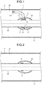
- FIG. 1 is a diagram illustrating a vertical cross-sectional configuration of a gas-insulated bus according to a first example and is a cross-sectional view along A-A line illustrated in FIG. 3 .
- FIG. 2 is a diagram illustrating another vertical cross-sectional configuration of the gas-insulated bus according to the first example and is a cross-sectional view along B-B line illustrated in FIG. 3 .
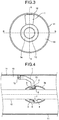
- FIG. 3 is a diagram illustrating a horizontal cross-sectional configuration of the gas-insulated bus according to the first example.
- a current-carrying conductor 10 is disposed along the axial direction of the pressure vessel 11.
- an insulating gas 15 such as SF 6 (sulfur hexafluoride) is hermetically filled.
- the current-carrying conductor 10 is supported by an insulating support 1 that is installed in the pressure vessel 11. That is, a first end of the insulating support 1 is fixed to a seat 12, which is installed on the inner surface of the pressure vessel 11, with fixing members such as bolts; and a second end of the insulating support 1 is fixed to the shield fitting 3a.
- the shield fitting 3a is barrel-like in shape with a substantially rotational symmetry around the axis of the current-carrying conductor 10 and has a depressed portion formed on a portion of the outer surface of the barrel shape.
- the second end of the insulating support 1 is fixed in that depressed portion. Since, the shield fitting 3a excluding the depressed portion has a barrel-like shape, a space is formed in between the inner surface of the shield fitting 3a and the outer surface of an internal conductor 2. By making use of that space, the shield fitting 3a is fixed to the insulating support 1 with fixing members 6 such as bolts.
- the second end of the insulating support 1, that is, that end of the insulating support 1 which is fixed to the shield fitting 3a has the internal conductor 2 made of a metallic material and implanted therein.
- a fixing member 6 is passed through the shield fitting 3a from the inside of the shield fitting 3a and is threaded into a hole formed on the internal conductor 2, the shield fitting 3a gets fixed to the internal conductor 2.
- the internal conductor 2 has such a shape that the internal conductor 2 and the shield fitting 3a together form a substantially barrel-like profile. That is, the outer surface of the internal conductor 2, which is disposed in the depressed portion, constitutes the barrel-like profile and is part of the entire substantially barrel-like shape in an integrated manner with the outer surface of the shield fitting 3a excluding the depressed portion. More particularly, as illustrated in FIG. 4 , if a virtual surface 51 is formed by extending the outer edge of the barrel-like portion of the shield fitting 3a above the depressed portion, the outer surface of the internal conductor 2 has such a shape which almost makes contact with the virtual surface 51.
- the cross-sectional profile of the depressed portion has a substantially L-shape that is inclined with respect to the axis line.
- the second end of the insulating support 1 is fixed to one of the inclined surfaces of the depressed portion. Moreover, that second end is drawn in an inclined direction with respect to a surface perpendicular to the axis line.
- ring-like insulating member 5 is disposed across the circumferential direction of the current-carrying conductor 10.
- the insulating member 5 makes contact with the current-carrying conductor 10 and supports, through the surface of contact thereof, the current-carrying conductor 10.
- the surface of contact of each insulating member 5 is formed to be smooth in nature so that the current-carrying conductor 10 is made slidable with respect to the shield fitting 3a.
- the insulating member 5 is disposed at the top of a wall 8, which is formed in a ring-like manner on the inner surface of the shield fitting 3a.
- the wall 8 is formed to have a constant height from the outer surface of the shield fitting 3a.
- the outer surface is recessed toward inside.
- the wall 8 decreases in height and becomes equal to the thickness of the shield fitting 3a at other places.
- the corresponding insulating member 5 is in a condition of being attached to the inner wall of the shield fitting 3a.
- a spring-shaped contact 4 On the side surface of the wall 8 is attached a spring-shaped contact 4 using attaching members 7 such as bolts.
- the contact 4 is disposed in the space created on the inside of the shield fitting 3a in an abutting manner with the current-carrying conductor 10.
- the contact 4 remains biased to the current-carrying conductor 10 so as to ensure that the shield fitting 3a makes contact with the current-carrying conductor 10 via the contact 4.
- the shield fitting 3a and the current-carrying conductor 10 are maintained at the same electric potential.
- FIG. 21 is a diagram in which the electric field distribution inside the pressure vessel 11 is illustrated for a configuration (a) according to the first example as well as for a conventional configuration (b).
- FIG. 21 (a) represents a schematic illustration of the pressure vessel 11, a barrel-shaped shield fitting 3, and the current-carrying conductor 10 as the configuration according to the first example; and (b) represents a schematic illustration of the pressure vessel 11, an insulating spacer 101, a cylindrical shield fitting 102, and the current-carrying conductor 10 as the configuration of a conventional gas-insulated bus.
- the shield fitting 3 is a schematic illustration of a substantially barrel-like shape formed when the shield fitting 3a and the internal conductor 2 are combined together.
- the electric field distribution inside the pressure vessel 11 is illustrated with respect to (a) as well as (b), with the horizontal axis representing positions in the axial direction and the vertical axis representing electric field values.
- the electric field goes on increasing from the center toward the end and reaches the peak in the vicinity of the end of the cylindrical shield fitting 102 (see (b)). That happens because of a smaller curvature at the end of the cylindrical shield fitting 102.
- the shield fitting 3 has a substantially barrel-like shape, which overall has only gradual changes. Hence, the electric field distribution is almost uniform with respect to the axial direction (see (a)).
- the electric field value in (a) is equivalent to the peak value in the conventional case.
- the average value of the electric field is higher as compared to the conventional case, it is possible to achieve a uniform electric field distribution on the whole within the acceptable range equal to or smaller than the design electric field value.
- the outer surface of the internal conductor 2 is illustrated to almost abut against the virtual surface 51.
- the shape of the internal conductor 2 is such that the outer surface thereof lies within the area of a predetermined width from the virtual surface 51, then it is possible to achieve the same advantages as achieved in the case when the outer surface makes contact with the virtual surface 51.
- the predetermined area can be, for example, within a range of ⁇ 30%; or can be favorably within a range of ⁇ 10%.
- the internal conductor 2 is shaped in such a way that the entire profile of the internal conductor 2 and the shield fitting 3a when viewed as a unit has a substantially barrel-like shape. That makes it possible to achieve an advantage that the electric field inside the pressure vessel 11 can be maintained at an almost uniform distribution and can be easily maintained at a value equal to or smaller than the design electric field value. As a result, a simple configuration can be achieved without causing any decline in the insulating capacity.
- the shield fitting 3a can be manufacture by, for example, doing bending work on a metal plate, which then can be fixed to the insulating support 1 with the fixing member 6.
- the manufacturing process is simplified as compared to the conventional technique of implanting a shield fitting inside an insulating support in an integrated manner.
- the shield fitting 3a by manufacturing the shield fitting 3a to have a substantially barrel-like profile, a space is created inside the shield fitting 3a and the fixing member 6 is disposed inside that space. That simplifies the task of fixing the shield fitting 3a to the insulating support 1. That is, the installation structure of the shield fitting 3a becomes simple thereby enabling the use of bolts or the like to fix the shield fitting 3a to the insulating support 1. In this way, according to the first example, by implementing such a shape that enables extensive approximation of the electric field distribution inside the pressure vessel 11 to the design electric field value, it becomes possible to secure an internal space in the shield fitting 3a. Hence, even in a limited space inside the pressure vessel 11, a simple installation structure for installing the shield fitting 3a can be achieved without causing any decline in the insulating capacity.
- the shield fitting 3a and the current-carrying conductor 10 can be maintained at the same electric potential with a simple configuration.
- the shield fitting 3a and the current-carrying conductor 10 need to be maintained at the same electric potential so as to prevent any decline in the insulating capacity.
- the insulating member 5 which provide slidable surfaces of contact with respect to the current-carrying conductor 10.
- the cross-sectional profile of the depressed portion has a substantially L-shape.
- any other shape can be applied as long as the shape is suitable in fixing the shield fitting 3a to the internal conductor 2.
- FIG. 5 is a diagram illustrating a vertical cross-sectional configuration of a gas-insulated bus according to a second example and is a cross-sectional view along B-B line illustrated in FIG. 7 .
- FIG. 6 is a diagram illustrating another vertical cross-sectional configuration of the gas-insulated bus according to the second example and is a cross-sectional view along A-A line illustrated in FIG. 7 .
- FIG. 7 is a diagram illustrating a horizontal cross-sectional configuration of the gas-insulated bus according to the second example.
- a shield fitting 3b is installed that has depressed portions formed at two positions on the outer surface of the barrel shape which encompasses the current-carrying conductor 10.
- the current-carrying conductor 10 is supported by two insulating supports 1.
- Each depressed portion has the same shape as the shape described in the first example.
- the two depressed portions are formed, for example, at an angle of 180° around the axis line (see FIG. 7 ). Accordingly, the two insulating supports 1 lie on a B-B plane.
- each insulating support 1 which is fixed to the shield fitting 3b has the internal conductor 2 implanted therein.
- Each internal conductor 2 is disposed in the corresponding depressed portion.
- the outer surface of each internal conductor 2 constitutes the barrel-like profile and is part of the entire substantially barrel-like shape in an integrated manner with the outer surface of the shield fitting 3b excluding the depressed portions.
- the insulating member 5 is disposed at the top of a wall 9, which is formed in a ring-like manner on the inner surface of the shield fitting 3b.
- the spring-shaped contact 4 On the side surface of the wall 9 is attached the spring-shaped contact 4.
- the contact 4 is disposed in the space created on the inside of the shield fitting 3b in an abutting manner with the current-carrying conductor 10. Consequently, the shield fitting 3b and the current-carrying conductor 10 are maintained at the same electric potential.
- the rest of the configuration is identical to the configuration according to the first example.
- the constituent elements identical to the constituent elements illustrated in FIGS. 1 to 3 are referred to by the same reference numerals and the explanation of such constituent elements is not repeated.
- the electric field distribution according to the second example is also identical to the electric field distribution illustrated in FIG. 21 .
- two insulating supports 1 are disposed in the configuration according to the second example, the support gets enhanced in strength.
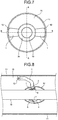
- FIG. 8 is a diagram illustrating a vertical cross-sectional configuration of a gas-insulated bus according to a third example and is a cross-sectional view along A-A line illustrated in FIG. 10.
- FIG. 9 is a diagram illustrating another vertical cross-sectional configuration of the gas-insulated bus according to the third example and is a cross-sectional view along B-B line illustrated in FIG. 10 .
- FIG. 10 is a diagram illustrating a horizontal cross-sectional configuration of the gas-insulated bus according to the third example.
- a shield fitting 3c is installed that has depressed portions formed at three positions on the outer surface of the barrel shape which encompasses the current-carrying conductor 10.
- the current-carrying conductor 10 is supported by three insulating supports 1.
- Each depressed portion has the same shape as the shape described in the first example.
- the three depressed portions are formed, for example, at an angle of 120° from each other around the axis line (see FIG. 10 ).
- each insulating support 1 which is fixed to the shield fitting 3c has the internal conductor 2 implanted therein.
- Each internal conductor 2 is disposed in the corresponding depressed portion.
- the outer surface of each internal conductor 2 constitutes the barrel-like profile and is part of the entire substantially barrel-like shape in an integrated manner with the outer surface of the shield fitting 3c excluding the depressed portions.
- the rest of the configuration is identical to the configurations according to the first examples.
- the constituent elements identical to the constituent elements illustrated in FIGS. 1 to 3 are referred to by the same reference numerals and the explanation of such constituent elements is not repeated.
- the electric field distribution according to the third example is also identical to the electric field distribution illustrated in FIG. 21 .
- since three insulating supports 1 are disposed in the configuration according to the third example the support is further enhanced in strength than the second example. Meanwhile, it is also possible to further increase the number of insulating supports 1.
- FIG. 11 is a diagram illustrating a vertical cross-sectional configuration of a gas-insulated bus according to a first embodiment and is a cross-sectional view along B-B line illustrated in FIG. 13 .
- FIG. 12 is a diagram illustrating another vertical cross-sectional configuration of the gas-insulated bus according to the first embodiment and is a cross-sectional view along A-A line illustrated in FIG. 13 .
- FIG. 13 is a diagram illustrating a horizontal cross-sectional configuration of the gas-insulated bus according to the first embodiment.
- a shield fitting 3d is installed that has notches formed at two positions on the outer surface of the barrel shape which encompasses the current-carrying conductor 10.
- the current-carrying conductor 10 is supported by two insulating supports 21.
- each insulating support 21 is fixed to the corresponding seat 12, which is installed on the inner surface of the pressure vessel 11, with fixing members such as bolts; and a second end of that insulating support 21 is fixed to the shield fitting 3d. More particularly, at two positions on one end of the barrel-shaped shield fitting 3d are formed notches, through which the second ends of the insulating supports 21 are inserted into the shield fitting 3d and are fixed using the fixing members 6 to a side surface 24 of a wall 23 that is erected in a ring-like manner along the circumferential direction on the inner surface of the shield fitting 3d.
- the side surface 24 is substantially perpendicular to the axis line so that the second ends of the insulating supports 21, which are fixed to the side surface 24, are drawn parallel to the direction of the axis line from the respective notches.
- the two insulating supports 21 are disposed, for example, at an angle of 180° around the axis line. Accordingly, the two insulating supports 21 lie on a B-B plane.
- each insulating support 1 has an internal conductor 22 implanted therein.
- Each internal conductor 22 is disposed in the corresponding notch.
- the outer surface of each internal conductor 22 constitutes the barrel-like profile and is part of the entire substantially barrel-like shape in an integrated manner with the outer surface of the shield fitting 3d excluding the notches. More particularly, as illustrated in FIG. 14 , if a virtual surface 52 is formed by extending the outer edge of the barrel-like portion of the shield fitting 3d above the notched portions, the outer surfaces of each internal conductor 22 has such a shape which almost makes contact with the corresponding virtual surface 52.
- the insulating member 5 is disposed at the top of the wall 23.
- the insulating members 5 provide slidable surfaces of contact with respect to the current-carrying conductor 10.
- the spring-shaped contact 4 which is disposed in the space created on the inside of the shield fitting 3d and which makes contact with the current-carrying conductor 10. Consequently, the shield fitting 3d and the current-carrying conductor 10 are maintained at the same electric potential.
- the first embodiment differs from the first example in the fact that it is the notches through which the insulating supports 21 are fixed to the shield fitting 3d.
- the explanation is given about the shape and installation structure of the insulating supports 21 that are different from the insulating support in the first example.
- the rest of the configuration is identical to the configuration according to the first example.
- the constituent elements identical to the constituent elements illustrated in FIGS. 1 to 3 are referred to by the same reference numerals and the explanation of such constituent elements is not repeated.
- the electric field distribution according to the first embodiment is also identical to the electric field distribution illustrated in FIG. 21 .
- the internal conductors 22 are shaped in such a way that the entire profile of the internal conductors 22 and the shield fitting 3d when viewed as a unit is substantially barrel-like in shape. That makes it possible to achieve an advantage that the electric field inside the pressure vessel can be maintained at an almost uniform distribution. Apart from that, the other advantages achieved in the first embodiment are identical to the advantages achieved in the first example.
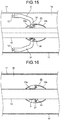
- FIG. 15 is a diagram illustrating a vertical cross-sectional configuration of a gas-insulated bus according to a fourth example and is a cross-sectional view along B-B line illustrated in FIG. 17 .
- FIG. 16 is a diagram illustrating another vertical cross-sectional configuration of the gas-insulated bus according to the fourth example and is a cross-sectional view along A-A line illustrated in FIG. 17 .
- FIG. 17 is a diagram illustrating a horizontal cross-sectional configuration of the gas-insulated bus according to the fourth example.
- a shield fitting 33 is installed that has depressed portions formed at two positions on the outer surface of the barrel shape which encompasses the current-carrying conductor 10.
- the shield fitting 33 has, for example, two component members. More particularly the shield fitting 33 is configured by coupling a shield member 33a and a shield member 33b that are made of a metallic material. The two depressed portions are formed on the shield member 33a. Meanwhile, the shield member 33a and the shield member 33b are coupled together by fastening with, for example, a fixing member 37 such as a bolt.
- each insulating support 31 is fixed to the seat 12, which is installed on the inner surface of the pressure vessel 11, with fixing members such as bolts; and a second end of each insulating support 31 is fixed to the shield fitting 33. More particularly, the second end of each insulating support 31 has an internal conductor 32 implanted therein. Each internal conductor 32 is disposed in the corresponding depressed portion.
- the shield member 33a is fixed to the second end of the corresponding insulating support 31 with a fixing member 36 such as a bolt.
- the fixing member 36 is passed through a hole, which is formed on the side surface of the shield member 33a facing the shield member 33b, and is threaded into a hole, which is formed on the internal conductor 32 implanted at the second end of that insulating support 31.
- the depressed portions formed on the shield fitting 33 have, for example, a U-shaped cross-sectional shape.
- the second end of each insulating support 31 is inserted in the corresponding depressed portion in a perpendicular manner to the axis line.
- the insulating member 5 is disposed on the inner surface of the shield fitting 33.
- the insulating members 5 provide slidable surfaces of contact with respect to the current-carrying conductor 10.
- a contact 34 is attached to the shield fitting 33 with the fixing member 37, which is used to couple the shield member 33a to the shield member 33b.
- the shield fitting 33 is configured with the shield members 33a and 33b that are, for example, the two divided component members. Hence, processing of the shield fitting 33 becomes easier and the installation structure of the contact 4 becomes simpler. Meanwhile, after inserting the second end of each insulating support 31 in the corresponding depressed portion which shape is U-shape in a perpendicular manner to the axis line, the second end and the shield member 33a can be coupled from the side surface.
- the shield fitting 33 can also be configured with three or more component members. Besides, the other advantages achieved in the fourth example are same as the advantages achieved in the first examples.
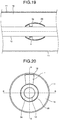
- FIG. 18 is a diagram illustrating a vertical cross-sectional configuration of a gas-insulated bus according to a fifth example and is a cross-sectional view along A-A line illustrated in FIG. 20.
- FIG. 19 is a diagram illustrating another vertical cross-sectional configuration of the gas-insulated bus according to the fifth example and is a cross-sectional view along B-B line illustrated in FIG. 20 .
- FIG. 20 is a diagram illustrating a horizontal cross-sectional configuration of the gas-insulated bus according to the fifth example.
- an insulating film 28 coated with an insulator As illustrated in FIGS. 18 to 20 , in the fifth example, on the outer surface of the shield fitting 3a is applied an insulating film 28 coated with an insulator. Similarly, the insulator coating can also be performed with respect to each of the shield fittings 3b, 3c, 3d, and 33d according to the fourth example. Meanwhile, in the fifth example, the rest of the configuration is identical to the configuration according to the first example. In FIGS. 18 to 20 , the constituent elements identical to the constituent elements illustrated in FIGS. 1 to 3 are referred to by the same reference numerals and the explanation of such constituent elements is not repeated.
- the outer surface of the shield fitting 3a is covered with the insulating film 28, it becomes possible to enhance the insulating capacity of the gas-insulated bus while reducing the insulating distance.
- gas-insulated bus according to the present invention can be suitably implemented at electric power plants or electric power substations.
Landscapes
- Installation Of Bus-Bars (AREA)
- Gas-Insulated Switchgears (AREA)
Claims (5)
- Gasisolierter Bus, umfassend:einen stromführenden Leiter (10), der entlang der axialen Richtung eines metallischen Behälters (11) angeordnet ist, der mit einem Isoliergas (15) gefüllt ist;eine Abschirmungsarmatur (3d), durch die der stromführende Leiter (10) hindurchtritt, die eine tonnenförmige Außenfläche hat, und die einen vertieften Abschnitt hat, der an einem Abschnitt an einem Ende ausgebildet ist;eine isolierende Halterung (21), die ein zweites Ende von sich an der Abschirmungsarmatur (3d) über dem vertieften Abschnitt fixiert hat, und die ein erstes Ende von sich am metallischen Behälter (11) fixiert hat, und die den stromführenden Leiter (10) über die Abschirmungsarmatur (3d) haltert;gekennzeichnet durch:einen Innenleiter (22), der in das zweite Ende der isolierenden Halterung (21) eingesetzt ist und sich zusammen mit dem zweiten Ende im vertieften Abschnitt befindet und an der Abschirmungsarmatur (3d) fixiert ist; undeinen Kontakt (4), der an der Innenfläche der Abschirmungsarmatur (3d) angebracht ist, der in einem auf der Innenseite der Abschirmungsarmatur (3d) ausgebildeten Raum angeordnet ist, und der einen Kontakt mit dem stromführenden Leiter (10) herstellt, um die Abschirmungsarmatur (3d) und den stromführenden Leiter (10) auf demselben elektrischen Potential zu halten, wobeider Innenleiter (22) eine solche Form hat, dass der Innenleiter (22) und die Abschirmungsarmatur (3d) zusammen ein im Wesentlichen tonnenartiges Profil bilden.
- Gasisolierter Bus nach Anspruch 1, wobei
auf der Innenfläche der Abschirmungsarmatur (3d) eine Wand (23) entlang der Umfangrichtung des stromführenden Leiters (10) ausgebildet ist, und
das zweite Ende an einer Seitenfläche der Wand (23) fixiert und parallel zur Achsenlinie gezogen ist. - Gasisolierter Bus nach Anspruch 1 oder 2, wobei
oben auf der Wand (23) ein ringartiges Isolierteil (5) entlang der Umfangsrichtung des stromführenden Leiters (10) angeordnet ist, und
durch eine gleitbewegliche Kontaktfläche davon das Isolierteil (5) einen Kontakt mit dem stromführenden Leiter (10) herstellt, um den stromführenden Leiter (10) zu unterstützen. - Gasisolierter Bus nach Anspruch 1, wobei eine Mehrzahl der isolierenden Halterung (1) an der Abschirmungsarmatur (3d) fixiert ist und der stromführende Leiter (10) von den isolierenden Halterungen (1) isolierend gehaltert ist.
- Gasisolierter Bus nach Anspruch 1, wobei ein isolierender Film (28) auf die Außenfläche der Abschirmungsarmatur (3d) aufgetragen ist.
Priority Applications (1)
| Application Number | Priority Date | Filing Date | Title |
|---|---|---|---|
| EP19178146.7A EP3553905B1 (de) | 2009-07-17 | 2009-07-17 | Gasisolierter bus |
Applications Claiming Priority (3)
| Application Number | Priority Date | Filing Date | Title |
|---|---|---|---|
| EP09847344.0A EP2456033B1 (de) | 2009-07-17 | 2009-07-17 | Gasisolierter bus |
| PCT/JP2009/062973 WO2011007446A1 (ja) | 2009-07-17 | 2009-07-17 | ガス絶縁母線 |
| EP19178146.7A EP3553905B1 (de) | 2009-07-17 | 2009-07-17 | Gasisolierter bus |
Related Parent Applications (2)
| Application Number | Title | Priority Date | Filing Date |
|---|---|---|---|
| EP09847344.0A Division EP2456033B1 (de) | 2009-07-17 | 2009-07-17 | Gasisolierter bus |
| EP09847344.0A Division-Into EP2456033B1 (de) | 2009-07-17 | 2009-07-17 | Gasisolierter bus |
Publications (2)
| Publication Number | Publication Date |
|---|---|
| EP3553905A1 EP3553905A1 (de) | 2019-10-16 |
| EP3553905B1 true EP3553905B1 (de) | 2021-02-17 |
Family
ID=42193835
Family Applications (2)
| Application Number | Title | Priority Date | Filing Date |
|---|---|---|---|
| EP09847344.0A Active EP2456033B1 (de) | 2009-07-17 | 2009-07-17 | Gasisolierter bus |
| EP19178146.7A Active EP3553905B1 (de) | 2009-07-17 | 2009-07-17 | Gasisolierter bus |
Family Applications Before (1)
| Application Number | Title | Priority Date | Filing Date |
|---|---|---|---|
| EP09847344.0A Active EP2456033B1 (de) | 2009-07-17 | 2009-07-17 | Gasisolierter bus |
Country Status (5)
| Country | Link |
|---|---|
| US (1) | US8587930B2 (de) |
| EP (2) | EP2456033B1 (de) |
| JP (1) | JP4436896B1 (de) |
| CN (1) | CN102474088B (de) |
| WO (1) | WO2011007446A1 (de) |
Families Citing this family (5)
| Publication number | Priority date | Publication date | Assignee | Title |
|---|---|---|---|---|
| WO2012066614A1 (ja) * | 2010-11-15 | 2012-05-24 | 三菱電機株式会社 | ガス絶縁母線 |
| WO2012117506A1 (ja) * | 2011-02-28 | 2012-09-07 | 三菱電機株式会社 | ガス絶縁母線 |
| JP2014030282A (ja) * | 2012-07-31 | 2014-02-13 | Hitachi Ltd | 三相一括型ガス絶縁母線 |
| KR101697626B1 (ko) * | 2014-12-31 | 2017-01-18 | 주식회사 효성 | 가스 절연 개폐장치용 절연스페이서 및 그 제조방법 |
| US12113345B2 (en) | 2019-04-25 | 2024-10-08 | Mitsubishi Electric Corporation | Gas insulated bus |
Family Cites Families (24)
| Publication number | Priority date | Publication date | Assignee | Title |
|---|---|---|---|---|
| GB1076940A (en) * | 1963-11-19 | 1967-07-26 | Sumitomo Electric Industries | Improvements in or relating to electric cables |
| US3324272A (en) * | 1965-07-26 | 1967-06-06 | Westinghouse Electric Corp | Termination of insulators |
| JPS4791Y1 (de) * | 1969-10-16 | 1972-01-06 | ||
| JPS521025Y2 (de) * | 1971-11-08 | 1977-01-11 | ||
| US3801725A (en) * | 1972-11-14 | 1974-04-02 | Westinghouse Electric Corp | Spacer construction for fluid-insulated transmission lines |
| US3829707A (en) * | 1973-02-09 | 1974-08-13 | Allis Chalmers | Gas insulated high voltage electrical transmission line with means for damping transients |
| DE2325449B2 (de) * | 1973-05-17 | 1978-09-14 | Siemens Ag, 1000 Berlin Und 8000 Muenchen | Spannungswandler für eine vollisolierte Hochspannungsschaltanlage |
| DE2347927C3 (de) * | 1973-09-24 | 1981-07-16 | Siemens AG, 1000 Berlin und 8000 München | Ringförmige Steuerelektrode für einen im wesentlichen trichterförmigen Stützisolator einer gekapselten, gasisolierten Hochspannungsrohrleitung |
| DE2360071C2 (de) * | 1973-11-29 | 1984-12-13 | Siemens AG, 1000 Berlin und 8000 München | Gekapselte mit Schwefelhexafluorid (SF↓6↓) isolierte Hochspannungseinrichtung |
| FR2472861A1 (fr) * | 1979-12-28 | 1981-07-03 | Alsthom Cgee | Dispositif de securite contre les arcs electriques |
| US4328391A (en) | 1981-01-19 | 1982-05-04 | The United States Of America As Represented By The United States Department Of Energy | Gas insulated transmission line having tapered particle trapping ring |
| JPS59175320A (ja) | 1983-03-25 | 1984-10-04 | 株式会社日立製作所 | ガス絶縁母線の導体支持装置 |
| KR900001481B1 (ko) * | 1984-04-18 | 1990-03-12 | 가부시기가이샤 히다찌세이사꾸쇼 | 가스절연 전기기기 및 그 조립방법 |
| JPH0687624B2 (ja) * | 1986-11-11 | 1994-11-02 | 株式会社日立製作所 | ガス絶縁電気機器用絶縁スペ−サ |
| US6002085A (en) * | 1991-11-18 | 1999-12-14 | Hitachi, Ltd. | Gas insulated switchgear |
| FR2714204B1 (fr) * | 1993-12-21 | 1996-01-19 | Gec Alsthom T & D Sa | Câble monophasé à isolation gazeuse pour le transport d'électricité. |
| FR2716521B1 (fr) * | 1994-02-18 | 1996-04-12 | Gec Alsthom T & D Sa | Raccord angulaire. |
| CN1212085A (zh) * | 1996-01-31 | 1999-03-24 | 西门子公司 | 带外壳的波导管 |
| DE19604481A1 (de) * | 1996-02-08 | 1997-08-14 | Asea Brown Boveri | Leitungsabschnitt einer gasisolierten Leitung |
| JPH10234113A (ja) * | 1997-02-19 | 1998-09-02 | Hitachi Ltd | ガス絶縁開閉装置 |
| EP1306954B1 (de) * | 2001-10-29 | 2011-07-27 | ABB Research Ltd. | GIS-Stützisolator mit integrierter Barriere |
| JP4429205B2 (ja) * | 2005-05-16 | 2010-03-10 | 三菱電機株式会社 | ガス絶縁機器 |
| FR2906073B1 (fr) * | 2006-09-14 | 2008-12-05 | Areva T & D Sa | Support isolant pour dispositif haute-ou moyenne-tension et dispositif le comprenant |
| JP4949919B2 (ja) * | 2007-04-24 | 2012-06-13 | 三菱電機株式会社 | ガス絶縁電気機器 |
-
2009
- 2009-07-17 EP EP09847344.0A patent/EP2456033B1/de active Active
- 2009-07-17 WO PCT/JP2009/062973 patent/WO2011007446A1/ja not_active Ceased
- 2009-07-17 CN CN200980160676.4A patent/CN102474088B/zh not_active Expired - Fee Related
- 2009-07-17 EP EP19178146.7A patent/EP3553905B1/de active Active
- 2009-07-17 JP JP2009544333A patent/JP4436896B1/ja not_active Expired - Fee Related
- 2009-07-17 US US13/377,035 patent/US8587930B2/en not_active Expired - Fee Related
Non-Patent Citations (1)
| Title |
|---|
| None * |
Also Published As
| Publication number | Publication date |
|---|---|
| EP2456033A4 (de) | 2017-01-18 |
| EP3553905A1 (de) | 2019-10-16 |
| JP4436896B1 (ja) | 2010-03-24 |
| US8587930B2 (en) | 2013-11-19 |
| EP2456033B1 (de) | 2020-04-01 |
| CN102474088A (zh) | 2012-05-23 |
| CN102474088B (zh) | 2014-08-27 |
| WO2011007446A1 (ja) | 2011-01-20 |
| US20120103645A1 (en) | 2012-05-03 |
| JPWO2011007446A1 (ja) | 2012-12-20 |
| EP2456033A1 (de) | 2012-05-23 |
Similar Documents
| Publication | Publication Date | Title |
|---|---|---|
| EP3553905B1 (de) | Gasisolierter bus | |
| US8227720B2 (en) | Vacuum switch and vacuum switchgear | |
| KR20130137664A (ko) | Hvdc 컴포넌트용 도관의 분리 포인트의 전기 차폐 장치 | |
| US20130025912A1 (en) | High-voltage insulator | |
| EP2284971B1 (de) | Kabelanschluss-verbindungsteil | |
| US7417847B2 (en) | Compact current transformer casing for gas-insulated switchgear assemblies | |
| EP2117015A1 (de) | Hochspannungsbuchse und Hochspannungsvorrichtung mit einer derartigen Buchse | |
| JP4781493B1 (ja) | ガス絶縁母線 | |
| JP2014030282A (ja) | 三相一括型ガス絶縁母線 | |
| US9269475B2 (en) | Gas-insulated bus bar | |
| US8420971B2 (en) | Switching chamber insulation arrangement for a circuit breaker | |
| CN108028525B (zh) | 直流高压绝缘体和所属的制造方法 | |
| EP4033502A1 (de) | Durchführungseinheit und stromkabelverbindungsstruktur für ein schienenfahrzeug | |
| CN103181046B (zh) | 多极气体绝缘母线段 | |
| JPH10247444A (ja) | ガス絶縁真空遮断器 | |
| RU236242U1 (ru) | Токопровод с газовой изоляцией | |
| CN110402471B (zh) | 电接触装置 | |
| US12113345B2 (en) | Gas insulated bus | |
| US20110247853A1 (en) | Gas bushing | |
| JP2004281415A (ja) | ガス絶縁真空遮断器 | |
| EP1715556A1 (de) | Trennwand | |
| US20180075962A1 (en) | Top head housing | |
| JP2000253547A (ja) | 三相一括形ガス絶縁母線 | |
| WO2019024977A1 (en) | CONDUCTIVE WIRE OUTPUT ARRANGEMENT |
Legal Events
| Date | Code | Title | Description |
|---|---|---|---|
| PUAI | Public reference made under article 153(3) epc to a published international application that has entered the european phase |
Free format text: ORIGINAL CODE: 0009012 |
|
| STAA | Information on the status of an ep patent application or granted ep patent |
Free format text: STATUS: REQUEST FOR EXAMINATION WAS MADE |
|
| 17P | Request for examination filed |
Effective date: 20190604 |
|
| AC | Divisional application: reference to earlier application |
Ref document number: 2456033 Country of ref document: EP Kind code of ref document: P |
|
| AK | Designated contracting states |
Kind code of ref document: A1 Designated state(s): AT BE BG CH CY CZ DE DK EE ES FI FR GB GR HR HU IE IS IT LI LT LU LV MC MK MT NL NO PL PT RO SE SI SK SM TR |
|
| STAA | Information on the status of an ep patent application or granted ep patent |
Free format text: STATUS: EXAMINATION IS IN PROGRESS |
|
| RBV | Designated contracting states (corrected) |
Designated state(s): AT BE BG CH CY CZ DE DK EE ES FI FR GB GR HR HU IE IS IT LI LT LU LV MC MK MT NL NO PL PT RO SE SI SK SM TR |
|
| 17Q | First examination report despatched |
Effective date: 20200527 |
|
| GRAP | Despatch of communication of intention to grant a patent |
Free format text: ORIGINAL CODE: EPIDOSNIGR1 |
|
| STAA | Information on the status of an ep patent application or granted ep patent |
Free format text: STATUS: GRANT OF PATENT IS INTENDED |
|
| INTG | Intention to grant announced |
Effective date: 20200914 |
|
| GRAS | Grant fee paid |
Free format text: ORIGINAL CODE: EPIDOSNIGR3 |
|
| GRAA | (expected) grant |
Free format text: ORIGINAL CODE: 0009210 |
|
| STAA | Information on the status of an ep patent application or granted ep patent |
Free format text: STATUS: THE PATENT HAS BEEN GRANTED |
|
| AC | Divisional application: reference to earlier application |
Ref document number: 2456033 Country of ref document: EP Kind code of ref document: P |
|
| AK | Designated contracting states |
Kind code of ref document: B1 Designated state(s): AT BE BG CH CY CZ DE DK EE ES FI FR GB GR HR HU IE IS IT LI LT LU LV MC MK MT NL NO PL PT RO SE SI SK SM TR |
|
| REG | Reference to a national code |
Ref country code: GB Ref legal event code: FG4D |
|
| REG | Reference to a national code |
Ref country code: CH Ref legal event code: NV Representative=s name: VALIPAT S.A. C/O BOVARD SA NEUCHATEL, CH Ref country code: CH Ref legal event code: EP |
|
| REG | Reference to a national code |
Ref country code: DE Ref legal event code: R096 Ref document number: 602009063364 Country of ref document: DE |
|
| REG | Reference to a national code |
Ref country code: AT Ref legal event code: REF Ref document number: 1362734 Country of ref document: AT Kind code of ref document: T Effective date: 20210315 |
|
| REG | Reference to a national code |
Ref country code: IE Ref legal event code: FG4D |
|
| REG | Reference to a national code |
Ref country code: LT Ref legal event code: MG9D |
|
| REG | Reference to a national code |
Ref country code: NL Ref legal event code: MP Effective date: 20210217 |
|
| PG25 | Lapsed in a contracting state [announced via postgrant information from national office to epo] |
Ref country code: NO Free format text: LAPSE BECAUSE OF FAILURE TO SUBMIT A TRANSLATION OF THE DESCRIPTION OR TO PAY THE FEE WITHIN THE PRESCRIBED TIME-LIMIT Effective date: 20210517 Ref country code: PT Free format text: LAPSE BECAUSE OF FAILURE TO SUBMIT A TRANSLATION OF THE DESCRIPTION OR TO PAY THE FEE WITHIN THE PRESCRIBED TIME-LIMIT Effective date: 20210617 Ref country code: LT Free format text: LAPSE BECAUSE OF FAILURE TO SUBMIT A TRANSLATION OF THE DESCRIPTION OR TO PAY THE FEE WITHIN THE PRESCRIBED TIME-LIMIT Effective date: 20210217 Ref country code: HR Free format text: LAPSE BECAUSE OF FAILURE TO SUBMIT A TRANSLATION OF THE DESCRIPTION OR TO PAY THE FEE WITHIN THE PRESCRIBED TIME-LIMIT Effective date: 20210217 Ref country code: BG Free format text: LAPSE BECAUSE OF FAILURE TO SUBMIT A TRANSLATION OF THE DESCRIPTION OR TO PAY THE FEE WITHIN THE PRESCRIBED TIME-LIMIT Effective date: 20210517 Ref country code: FI Free format text: LAPSE BECAUSE OF FAILURE TO SUBMIT A TRANSLATION OF THE DESCRIPTION OR TO PAY THE FEE WITHIN THE PRESCRIBED TIME-LIMIT Effective date: 20210217 Ref country code: GR Free format text: LAPSE BECAUSE OF FAILURE TO SUBMIT A TRANSLATION OF THE DESCRIPTION OR TO PAY THE FEE WITHIN THE PRESCRIBED TIME-LIMIT Effective date: 20210518 |
|
| REG | Reference to a national code |
Ref country code: AT Ref legal event code: MK05 Ref document number: 1362734 Country of ref document: AT Kind code of ref document: T Effective date: 20210217 |
|
| PG25 | Lapsed in a contracting state [announced via postgrant information from national office to epo] |
Ref country code: LV Free format text: LAPSE BECAUSE OF FAILURE TO SUBMIT A TRANSLATION OF THE DESCRIPTION OR TO PAY THE FEE WITHIN THE PRESCRIBED TIME-LIMIT Effective date: 20210217 Ref country code: PL Free format text: LAPSE BECAUSE OF FAILURE TO SUBMIT A TRANSLATION OF THE DESCRIPTION OR TO PAY THE FEE WITHIN THE PRESCRIBED TIME-LIMIT Effective date: 20210217 Ref country code: NL Free format text: LAPSE BECAUSE OF FAILURE TO SUBMIT A TRANSLATION OF THE DESCRIPTION OR TO PAY THE FEE WITHIN THE PRESCRIBED TIME-LIMIT Effective date: 20210217 Ref country code: SE Free format text: LAPSE BECAUSE OF FAILURE TO SUBMIT A TRANSLATION OF THE DESCRIPTION OR TO PAY THE FEE WITHIN THE PRESCRIBED TIME-LIMIT Effective date: 20210217 |
|
| PG25 | Lapsed in a contracting state [announced via postgrant information from national office to epo] |
Ref country code: IS Free format text: LAPSE BECAUSE OF FAILURE TO SUBMIT A TRANSLATION OF THE DESCRIPTION OR TO PAY THE FEE WITHIN THE PRESCRIBED TIME-LIMIT Effective date: 20210617 |
|
| PG25 | Lapsed in a contracting state [announced via postgrant information from national office to epo] |
Ref country code: AT Free format text: LAPSE BECAUSE OF FAILURE TO SUBMIT A TRANSLATION OF THE DESCRIPTION OR TO PAY THE FEE WITHIN THE PRESCRIBED TIME-LIMIT Effective date: 20210217 Ref country code: SM Free format text: LAPSE BECAUSE OF FAILURE TO SUBMIT A TRANSLATION OF THE DESCRIPTION OR TO PAY THE FEE WITHIN THE PRESCRIBED TIME-LIMIT Effective date: 20210217 Ref country code: EE Free format text: LAPSE BECAUSE OF FAILURE TO SUBMIT A TRANSLATION OF THE DESCRIPTION OR TO PAY THE FEE WITHIN THE PRESCRIBED TIME-LIMIT Effective date: 20210217 Ref country code: CZ Free format text: LAPSE BECAUSE OF FAILURE TO SUBMIT A TRANSLATION OF THE DESCRIPTION OR TO PAY THE FEE WITHIN THE PRESCRIBED TIME-LIMIT Effective date: 20210217 |
|
| REG | Reference to a national code |
Ref country code: DE Ref legal event code: R097 Ref document number: 602009063364 Country of ref document: DE |
|
| PG25 | Lapsed in a contracting state [announced via postgrant information from national office to epo] |
Ref country code: SK Free format text: LAPSE BECAUSE OF FAILURE TO SUBMIT A TRANSLATION OF THE DESCRIPTION OR TO PAY THE FEE WITHIN THE PRESCRIBED TIME-LIMIT Effective date: 20210217 Ref country code: RO Free format text: LAPSE BECAUSE OF FAILURE TO SUBMIT A TRANSLATION OF THE DESCRIPTION OR TO PAY THE FEE WITHIN THE PRESCRIBED TIME-LIMIT Effective date: 20210217 Ref country code: DK Free format text: LAPSE BECAUSE OF FAILURE TO SUBMIT A TRANSLATION OF THE DESCRIPTION OR TO PAY THE FEE WITHIN THE PRESCRIBED TIME-LIMIT Effective date: 20210217 |
|
| PLBE | No opposition filed within time limit |
Free format text: ORIGINAL CODE: 0009261 |
|
| STAA | Information on the status of an ep patent application or granted ep patent |
Free format text: STATUS: NO OPPOSITION FILED WITHIN TIME LIMIT |
|
| 26N | No opposition filed |
Effective date: 20211118 |
|
| PG25 | Lapsed in a contracting state [announced via postgrant information from national office to epo] |
Ref country code: ES Free format text: LAPSE BECAUSE OF FAILURE TO SUBMIT A TRANSLATION OF THE DESCRIPTION OR TO PAY THE FEE WITHIN THE PRESCRIBED TIME-LIMIT Effective date: 20210217 |
|
| PG25 | Lapsed in a contracting state [announced via postgrant information from national office to epo] |
Ref country code: SI Free format text: LAPSE BECAUSE OF FAILURE TO SUBMIT A TRANSLATION OF THE DESCRIPTION OR TO PAY THE FEE WITHIN THE PRESCRIBED TIME-LIMIT Effective date: 20210217 |
|
| GBPC | Gb: european patent ceased through non-payment of renewal fee |
Effective date: 20210717 |
|
| PG25 | Lapsed in a contracting state [announced via postgrant information from national office to epo] |
Ref country code: MC Free format text: LAPSE BECAUSE OF FAILURE TO SUBMIT A TRANSLATION OF THE DESCRIPTION OR TO PAY THE FEE WITHIN THE PRESCRIBED TIME-LIMIT Effective date: 20210217 |
|
| REG | Reference to a national code |
Ref country code: BE Ref legal event code: MM Effective date: 20210731 |
|
| PG25 | Lapsed in a contracting state [announced via postgrant information from national office to epo] |
Ref country code: IT Free format text: LAPSE BECAUSE OF FAILURE TO SUBMIT A TRANSLATION OF THE DESCRIPTION OR TO PAY THE FEE WITHIN THE PRESCRIBED TIME-LIMIT Effective date: 20210217 Ref country code: GB Free format text: LAPSE BECAUSE OF NON-PAYMENT OF DUE FEES Effective date: 20210717 |
|
| PG25 | Lapsed in a contracting state [announced via postgrant information from national office to epo] |
Ref country code: IS Free format text: LAPSE BECAUSE OF FAILURE TO SUBMIT A TRANSLATION OF THE DESCRIPTION OR TO PAY THE FEE WITHIN THE PRESCRIBED TIME-LIMIT Effective date: 20210617 Ref country code: LU Free format text: LAPSE BECAUSE OF NON-PAYMENT OF DUE FEES Effective date: 20210717 |
|
| PG25 | Lapsed in a contracting state [announced via postgrant information from national office to epo] |
Ref country code: IE Free format text: LAPSE BECAUSE OF NON-PAYMENT OF DUE FEES Effective date: 20210717 Ref country code: BE Free format text: LAPSE BECAUSE OF NON-PAYMENT OF DUE FEES Effective date: 20210731 |
|
| PG25 | Lapsed in a contracting state [announced via postgrant information from national office to epo] |
Ref country code: CY Free format text: LAPSE BECAUSE OF FAILURE TO SUBMIT A TRANSLATION OF THE DESCRIPTION OR TO PAY THE FEE WITHIN THE PRESCRIBED TIME-LIMIT Effective date: 20210217 |
|
| P01 | Opt-out of the competence of the unified patent court (upc) registered |
Effective date: 20230512 |
|
| REG | Reference to a national code |
Ref country code: DE Ref legal event code: R084 Ref document number: 602009063364 Country of ref document: DE |
|
| PG25 | Lapsed in a contracting state [announced via postgrant information from national office to epo] |
Ref country code: HU Free format text: LAPSE BECAUSE OF FAILURE TO SUBMIT A TRANSLATION OF THE DESCRIPTION OR TO PAY THE FEE WITHIN THE PRESCRIBED TIME-LIMIT; INVALID AB INITIO Effective date: 20090717 |
|
| PGFP | Annual fee paid to national office [announced via postgrant information from national office to epo] |
Ref country code: FR Payment date: 20230608 Year of fee payment: 15 |
|
| PGFP | Annual fee paid to national office [announced via postgrant information from national office to epo] |
Ref country code: CH Payment date: 20230801 Year of fee payment: 15 |
|
| PGFP | Annual fee paid to national office [announced via postgrant information from national office to epo] |
Ref country code: DE Payment date: 20230531 Year of fee payment: 15 |
|
| PG25 | Lapsed in a contracting state [announced via postgrant information from national office to epo] |
Ref country code: MK Free format text: LAPSE BECAUSE OF FAILURE TO SUBMIT A TRANSLATION OF THE DESCRIPTION OR TO PAY THE FEE WITHIN THE PRESCRIBED TIME-LIMIT Effective date: 20210217 |
|
| PG25 | Lapsed in a contracting state [announced via postgrant information from national office to epo] |
Ref country code: TR Free format text: LAPSE BECAUSE OF FAILURE TO SUBMIT A TRANSLATION OF THE DESCRIPTION OR TO PAY THE FEE WITHIN THE PRESCRIBED TIME-LIMIT Effective date: 20210217 |
|
| PG25 | Lapsed in a contracting state [announced via postgrant information from national office to epo] |
Ref country code: MT Free format text: LAPSE BECAUSE OF FAILURE TO SUBMIT A TRANSLATION OF THE DESCRIPTION OR TO PAY THE FEE WITHIN THE PRESCRIBED TIME-LIMIT Effective date: 20210217 |
|
| REG | Reference to a national code |
Ref country code: DE Ref legal event code: R119 Ref document number: 602009063364 Country of ref document: DE |
|
| REG | Reference to a national code |
Ref country code: CH Ref legal event code: PL |
|
| PG25 | Lapsed in a contracting state [announced via postgrant information from national office to epo] |
Ref country code: DE Free format text: LAPSE BECAUSE OF NON-PAYMENT OF DUE FEES Effective date: 20250201 |
|
| PG25 | Lapsed in a contracting state [announced via postgrant information from national office to epo] |
Ref country code: CH Free format text: LAPSE BECAUSE OF NON-PAYMENT OF DUE FEES Effective date: 20240731 |
|
| PG25 | Lapsed in a contracting state [announced via postgrant information from national office to epo] |
Ref country code: FR Free format text: LAPSE BECAUSE OF NON-PAYMENT OF DUE FEES Effective date: 20240731 |