EP3553899B1 - Crimpwerkzeug - Google Patents
Crimpwerkzeug Download PDFInfo
- Publication number
- EP3553899B1 EP3553899B1 EP18166729.6A EP18166729A EP3553899B1 EP 3553899 B1 EP3553899 B1 EP 3553899B1 EP 18166729 A EP18166729 A EP 18166729A EP 3553899 B1 EP3553899 B1 EP 3553899B1
- Authority
- EP
- European Patent Office
- Prior art keywords
- pliers
- spring
- crimping
- working stroke
- pressing
- Prior art date
- Legal status (The legal status is an assumption and is not a legal conclusion. Google has not performed a legal analysis and makes no representation as to the accuracy of the status listed.)
- Active
Links
Images


Classifications
-
- B—PERFORMING OPERATIONS; TRANSPORTING
- B25—HAND TOOLS; PORTABLE POWER-DRIVEN TOOLS; MANIPULATORS
- B25B—TOOLS OR BENCH DEVICES NOT OTHERWISE PROVIDED FOR, FOR FASTENING, CONNECTING, DISENGAGING OR HOLDING
- B25B27/00—Hand tools, specially adapted for fitting together or separating parts or objects whether or not involving some deformation, not otherwise provided for
- B25B27/14—Hand tools, specially adapted for fitting together or separating parts or objects whether or not involving some deformation, not otherwise provided for for assembling objects other than by press fit or detaching same
- B25B27/146—Clip clamping hand tools
-
- H—ELECTRICITY
- H01—ELECTRIC ELEMENTS
- H01R—ELECTRICALLY-CONDUCTIVE CONNECTIONS; STRUCTURAL ASSOCIATIONS OF A PLURALITY OF MUTUALLY-INSULATED ELECTRICAL CONNECTING ELEMENTS; COUPLING DEVICES; CURRENT COLLECTORS
- H01R43/00—Apparatus or processes specially adapted for manufacturing, assembling, maintaining, or repairing of line connectors or current collectors or for joining electric conductors
- H01R43/04—Apparatus or processes specially adapted for manufacturing, assembling, maintaining, or repairing of line connectors or current collectors or for joining electric conductors for forming connections by deformation, e.g. crimping tool
- H01R43/042—Hand tools for crimping
-
- B—PERFORMING OPERATIONS; TRANSPORTING
- B25—HAND TOOLS; PORTABLE POWER-DRIVEN TOOLS; MANIPULATORS
- B25B—TOOLS OR BENCH DEVICES NOT OTHERWISE PROVIDED FOR, FOR FASTENING, CONNECTING, DISENGAGING OR HOLDING
- B25B27/00—Hand tools, specially adapted for fitting together or separating parts or objects whether or not involving some deformation, not otherwise provided for
- B25B27/14—Hand tools, specially adapted for fitting together or separating parts or objects whether or not involving some deformation, not otherwise provided for for assembling objects other than by press fit or detaching same
-
- B—PERFORMING OPERATIONS; TRANSPORTING
- B25—HAND TOOLS; PORTABLE POWER-DRIVEN TOOLS; MANIPULATORS
- B25B—TOOLS OR BENCH DEVICES NOT OTHERWISE PROVIDED FOR, FOR FASTENING, CONNECTING, DISENGAGING OR HOLDING
- B25B7/00—Pliers; Other hand-held gripping tools with jaws on pivoted limbs; Details applicable generally to pivoted-limb hand tools
- B25B7/14—Locking means
- B25B7/16—Locking means combined with means for tightening the operating arms of jaws
-
- H—ELECTRICITY
- H01—ELECTRIC ELEMENTS
- H01R—ELECTRICALLY-CONDUCTIVE CONNECTIONS; STRUCTURAL ASSOCIATIONS OF A PLURALITY OF MUTUALLY-INSULATED ELECTRICAL CONNECTING ELEMENTS; COUPLING DEVICES; CURRENT COLLECTORS
- H01R43/00—Apparatus or processes specially adapted for manufacturing, assembling, maintaining, or repairing of line connectors or current collectors or for joining electric conductors
- H01R43/04—Apparatus or processes specially adapted for manufacturing, assembling, maintaining, or repairing of line connectors or current collectors or for joining electric conductors for forming connections by deformation, e.g. crimping tool
- H01R43/042—Hand tools for crimping
- H01R43/0425—Hand tools for crimping with mandrels actuated in axial direction to the wire
-
- Y—GENERAL TAGGING OF NEW TECHNOLOGICAL DEVELOPMENTS; GENERAL TAGGING OF CROSS-SECTIONAL TECHNOLOGIES SPANNING OVER SEVERAL SECTIONS OF THE IPC; TECHNICAL SUBJECTS COVERED BY FORMER USPC CROSS-REFERENCE ART COLLECTIONS [XRACs] AND DIGESTS
- Y10—TECHNICAL SUBJECTS COVERED BY FORMER USPC
- Y10T—TECHNICAL SUBJECTS COVERED BY FORMER US CLASSIFICATION
- Y10T29/00—Metal working
- Y10T29/53—Means to assemble or disassemble
- Y10T29/5313—Means to assemble electrical device
- Y10T29/532—Conductor
- Y10T29/53209—Terminal or connector
- Y10T29/53213—Assembled to wire-type conductor
- Y10T29/53222—Means comprising hand-manipulatable implement
- Y10T29/53226—Fastening by deformation
Definitions
- the present invention relates to crimping pliers.
- the pressing or crimping pliers can be used to manually actuate hand levers to press or crimp a workpiece.
- the crimp produced for a closed crimp can be, for example, a hexagonal or hexagonal crimp, a square crimp, a B crimp, a trapezoid crimp, a modified trapezoid crimp, an oval crimp, a mandrel crimp or a two-mandrel crimp.
- An open crimp can be designed, for example, as a V crimp or B crimp, as a roll crimp or as a double roll crimp.
- a generic crimping tool is preferably used for the mechanical fluid-tight connection in fluid technology, for example to connect pipes to one another or to fluidic connectors.
- plastic deformation of the pipes to be connected or a so-called fitting ensuring the mechanical connection and the fluid-tight seal takes place by means of the pressing tongs.
- Exemplary embodiments of a generic pressing tongs can be found in the publications DE 197 09 639 A1 , DE 198 34 859 C2 , DE 199 24 086 C2 , DE 199 24 087 C2 , DE 199 63 097 C1 , DE 103 46 241 B3 , DE 10 2007 001 235 B4 , DE 10 2008 005 472 B3 , EP 3 208 044 A1 , EP 2 995 424 A1 can be removed.
- U.S. 5,280,716 A discloses crimping pliers in which a fixed pliers part forms a fixed hand lever and a fixed pliers jaw.
- a movable pliers jaw is mounted on the fixed pliers part via a pivot bearing.
- a movable hand lever is articulated on the movable pliers jaw.
- the movable hand lever is additionally supported on the fixed hand lever via a pressure lever.
- a first spring is articulated with a spring base between the pivot bearing and the articulation of the pressure lever on the movable hand lever, while the other spring foot point is articulated on the fixed hand lever. The first spring acts on the movable hand lever in the opening direction.
- a second spring which is designed as a torsion leg spring, acts on the pressure lever in the opening direction.
- the crimping pliers assume an open position without the hand of the user acting on the hand lever, while an at least partial closure of the hand lever requires the user to apply closing forces to the hand lever.
- the bolt via which the pressure lever is articulated to the movable hand lever, is guided in an elongated hole, with which it can assume a first position and a second position.
- the bolt From the open position to a partially closed position, the bolt assumes the first position, in which the drive connection designed as a toggle lever drive has a relatively large transmission ratio, with which small forces are generated in the area of the pincer jaws, but large closing angles of the pincer jaws can be brought about.
- the partially closed position for which the dies held on the pliers jaws are just resting on the outer surface of the workpiece, the bolt is automatically transferred to the second position due to the alignment of the elongated hole, which means that the drive connection is switched to a smaller translation, with which then larger forces can be brought about on the pliers jaws.
- Intermediate locking positions can be secured using a compulsory lock.
- Another crimping tool is off WO 93/19897 A1 known.
- the invention is based on the object of proposing manually operated crimping or crimping pliers which are improved in terms of force ratios, ease of use and safety.
- conflicting objectives cannot be resolved.
- the manufacturer of the crimping or crimping pliers had to decide between a spring acting in the opening direction or a spring acting in the closing direction.
- pressing or crimping pliers which have two pliers jaws (supporting or forming dies).
- the pliers jaws are drive-connected via a suitable drive mechanism with two hand levers.
- a working stroke of the tong jaws from an open position of the tong jaws into a closed position of the tong jaws can be brought about by relative movement of the hand lever.
- the working stroke can have an "idle stroke" in which the dies are first placed against the workpiece, as well as a press or crimp stroke in which the workpiece is pressed or crimped between the dies.
- At least one spring device is used in the pressing or crimping pliers according to the invention.
- the at least one spring device is designed in a special way within the scope of the invention and is integrated into the force flow: the at least one spring device initially ensures an equilibrium position. In the equilibrium position, the spring device does not exert any force on the jaws. In the event that a single spring device is used, this spring device is not tensioned in the equilibrium position (or is only tensioned to such a small extent that friction or any other resistance in the crimping pliers cannot be overcome). In the event that several spring devices are used, none of them can be tensioned or the action of the tensioned spring devices cancels one another.
- the said equilibrium position the pincer jaw is arranged between the open position and the closed position of the pincer jaws (for example between 20% to 80% or 30% to 60% of the working stroke).
- the equilibrium position divides the working stroke into a first partial working stroke, which is arranged between the open position and the equilibrium position of the gripper jaws, and a second partial working stroke, which is arranged between the equilibrium position and the closed position.
- the at least one spring device exerts a closing force on the gripper jaws.
- the spring device exerts an opening force on the jaws in the second partial working stroke.
- the spring device preferably generates a non-linear characteristic of the spring force.
- the non-linear characteristic of the spring force exhibits a kink and / or a jump, particularly in the equilibrium position or between the two partial working strokes.
- the spring device can have one or more springs.
- the at least one spring can be made from any material (for example metal, plastic, an elastomer material) and also from a composite material. It can be a compression spring, tension spring, an angle spring, a torsion spring or a spring of any other type. If several springs are used, they can be arranged in mechanical series connection or parallel connection and / or integrated into the force flow at different points. It is also possible that one spring acts in the opening direction and another spring acts in the closing direction.
- the spring device preferably generates a non-linear characteristic which, in particular, has a kink and / or a jump in the equilibrium position or between the two partial working strokes.
- the spring device has a closing spring and an opening spring.
- the closing spring generates the closing force in the first partial working stroke
- the opening spring generates the opening force in the second partial working stroke. It is possible here that the opening spring is decoupled from the drive connection in the first partial working stroke, while the closing spring can be decoupled from the drive connection in the second partial working stroke.
- the spring device (preferably exclusively) has a spring.
- This spring is then used multifunctionally in that it generates the closing force in the first partial working stroke as well as generating the opening force in the second partial working stroke.
- a spring of the spring device to be coupled to the movement of the tong jaws over the entire working stroke. In this case changed the loading of the spring over the entire working stroke.
- the pressing or crimping pliers have at least one stop.
- the stop specifies an extreme deflection of a spring base point of the spring device, which is preferably a minimal deflection.
- a driver is available for this embodiment of the pressing or crimping pliers. In the partial working stroke, the driver takes the spring base point of the spring device with it and moves it away from the stop, which then changes the action on the spring.
- the spring base of the spring device preferably remains at the stop in the other partial working stroke. Thus, the application of the spring does not change for the other partial working stroke.
- the stop specifies a minimal application of pressure to the compression spring.
- the compressive force in the compression spring increases.
- the increasing compressive force of the compression spring can then be used to generate the closing force or the opening force.
- the stop provides a minimum tensile force in the tension spring, while the deflection and the tensile force increase as the driver continues to act on the tension spring.
- each spring can be supported on an associated stop in the equilibrium position.
- a driver moves the spring base point of a spring away from the assigned stop, while the other spring base point remains at the assigned stop.
- the other driver then moves the spring base of the other spring away from the associated stop, while in this case the spring base of the first-mentioned spring continues to be supported on the stop.
- the at least one stop and the at least one driver can be arranged on any components of the crimping or crimping pliers, as long as one during the working stroke Relative movement of the components on which the stop and the driver are arranged takes place.
- the driver it is possible for the driver to be supported on a hand lever, while the assigned stop is attached to a (preferably moved) pliers jaw.
- the stop is attached to a pliers head or carried by this, while the driver is attached to or carried by a pliers jaw moved over the working stroke with respect to the pliers head. If there are two stops and drivers, this can also apply to both stops and drivers.
- the at least one spring of the spring device can be designed as desired.
- a single spring is used, which is designed as a U-shaped spiral spring or leaf spring.
- Such a spiral spring or leaf spring represents a structurally simple spring with a long service life, in which the cross sections of the spiral spring or leaf spring and possibly the cross-sectional profile, the course of the longitudinal axis of the spiral spring or leaf spring, the material used and the effective length of the spiral spring or leaf spring the stiffness and any non-linearity of the stiffness behavior can be specified constructively. Because the spiral spring or leaf spring is U-shaped, the different spring arms of the U can be used to configure the rigidity.
- a particularly good integration of the U-shaped spiral spring or leaf spring into the pressing or crimping pliers can result for an embodiment of the invention if the spring arms of the U-shaped spiral spring or leaf spring extend in the direction of a longitudinal axis of the pliers head or in the direction of the closed hand lever .
- the crimping or crimping tool is equipped with an automatic lock.
- a compulsory lock secures a partial closed position of the jaws against an opening that has been reached.
- a partial closed position is maintained even if the manual forces acting on the hand lever are temporarily eliminated.
- Such a compulsory lock enables the jaws to be opened only when the working stroke has been completed. With these measures, the process reliability can be increased.
- the spring device automatically moves the gripper jaws back into the equilibrium position when the working stroke is fully completed (that is, when the automatic locking mechanism is unlocked).
- the automatic locking mechanism is designed in such a way that it is only effective in the second partial working stroke (or only in an end partial section of the same), so that this does not hinder the desired effect of the spring device in the first partial working stroke.
- the open position in which the workpiece can be inserted into the jaws of the pliers
- the open position is only maintained in view of the action of the spring device if the user applies opening forces to the hand lever or the pliers jaws, which the force of the action of the pliers jaws counteract by the spring device.
- a latching device or a locking device is available for this suggestion. The latching device or locking device secures the open position so that the open position can be automatically maintained despite the closing force of the spring device acting in the open position.
- a locking device is understood to mean, in particular, a device that effects a locking that leads to a locking force that is greater than the closing force generated by the spring device.
- a locking device is understood to mean in particular a device in which an open position is locked in such a way that it cannot be left simply by applying closing forces (for example via the hand lever or by closing forces applied directly to the pliers jaws). Rather, manual actuation of a locking element is required, which then releases the locking so that the spring device can then bring the pliers jaws back into the equilibrium position or bring the dies to the workpiece.
- the spring or a spring of the spring device is multifunctional in that this spring generates the opening force and / or the closing force on the one hand. In addition, this spring also generates a locking force of the locking device or a locking force of the locking device.
- a spring arm of the U-shaped leaf spring or spiral spring carries a latching spring arm of the latching device.
- the detent spring arm resiliently forms a detent element or carries it.
- the latching element interacts with a latching counter-latching element, with a relative movement of the counter-latching element relative to the latching element taking place over the working stroke and in particular in the area surrounding the open position.
- a fixed pliers part (which can be made in one or more pieces) forms a fixed pliers jaw and a fixed hand lever out.
- a movable pliers part (which can also be designed in one or more pieces) then forms a movable pliers jaw.
- the movable tong part is pivotably articulated to the fixed tong part via a pivot bearing.
- a movable hand lever is pivotably articulated to the fixed pliers part via a pivot bearing.
- the movable hand lever is then connected to the movable pliers part via a drive connection (in particular a pressure lever drive or a toggle lever drive).
- the movable hand lever forms the counter-locking element in this case.
- the pivot bearing via which the movable pliers part is pivotably articulated to the fixed pliers part, is arranged in the half of the longitudinal extension of the fixed pliers part facing away from the pliers head (the pivot bearing in this case, for example Can be located at a distance from the front end region of the long head which is more than 55%, more than 60%, more than 65%, more than 70% or even more than 75% of the length of the fixed pliers part).
- the pivot bearing away from the pliers head the pivot radius of the dies can also be increased.
- the swivel angle of the dies can be reduced over the working stroke in this way. Too much pivoting of the dies relative to one another has proven to be negative for the pressing or crimping result.
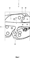
- Figs. 1 to 11 show a crimping tool 1 in panel construction.
- the crimping pliers 1 has a fixed pliers part 2 and a movable pliers part 3.
- the fixed pliers part 2 has two fixed ones
- the movable tong part 3 has two movable tong part plates 5a, 5b.
- the fixed pliers part 2 has a fixed pliers jaw 6, a connection area 7 and a fixed hand lever 8.
- the fixed pliers part plate 4a forms the fixed pliers jaw 6, the connection area 7 and the fixed hand lever 8.
- the fixed pliers part plate 4b only forms the fixed pliers jaw 6 and the connecting area 7.
- the movable tong part 3 has a movable tong jaw 9.
- the movable tong jaw 9 is held on a pivot bracket 10.
- the movable tong part plates 5a, 5b are designed in two parts with tong jaw plates 11a, 11b and pivoting support plates 12a, 12b.
- the movable tong part 3 is mounted on the fixed tong part 2 via a pivot bearing 13 so as to be pivotable about a pivot axis 14. In the illustrated embodiment, this is done by a pivot pin 15.
- the pivot pin 15 extends through through bores 16a, 16b, 16c, 16d of the movable pliers part plates 5a, 5b and fixed pliers part plates 4a, 4b, which allow pivoting.
- the two movable pliers part plates 5a, 5b are received between the fixed pliers part plates 4a, 4b.
- the tong jaw plates 11a, 11b are attached to the pivoting support plates 12a, 12b and held thereon such that the tong jaw plates 11a, 11b extend in the parallel planes given by the fixed tong part plates 4a, 4b and move in these planes during the pivoting.
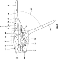
- a pressure lever 18 (which is formed here with two pressure lever plates 19a, 19b) is articulated to the movable pliers part 3 via a pivot bearing 17.
- the pivot bearing 17 is formed with a pivot pin 20.
- the pivot bolt 20 is received in through bores 21a, 21b, 21c, 21d of the pressure lever plate 19b, the pivot support plate 12b, the pivot support plate 12a and the pressure lever plate 19a. In this way, a pivot axis 22 of the pivot bearing 17 is predetermined.
- the two pressure lever plates 19 are not arranged between the fixed pliers part plates 4a, 4b, but outside the same.
- the pivot pin 20 extends through elongated holes 23a, 23b of the fixed pliers part plates 4a, 4b.
- the elongated holes 23a, 23b are shaped and arranged in such a way that the fixed tong part plates 4a, 4b do not hinder the movement of the pivot pin 20 with the pivoting of the movable tong part 3.
- a movable hand lever 24 (which here has two movable hand lever plates 25a, 25b) is mounted on the fixed pliers part 2 such that it can pivot via a pivot bearing 26 with a pivot axis 27.
- the fixed pliers part plate 4b, the hand lever plate 25b, the hand lever plate 25a and the fixed pliers part plate 4a have through bores 28a, 28b, 28c, 28d.
- a pivot bolt 29 extends through the through bores 28a, 28b, 28c, 28d. The pivot bolt 29 enables a relative pivoting movement of the movable hand lever 24 with respect to the fixed pliers part 2.
- the pressure lever 18 is pivotably connected to the hand lever 24 via a pivot bearing 30.
- the pressure lever plates 19a, 19b have through bores 31a, 31d.
- the hand lever plates 25a, 25b have through bores 31b, 31c adjacent to the through bores 28b, 28c.
- a pivot pin 32 which enables a pivoting movement, extends through the through bores 31b, 31c. Since for this purpose the pivot pin 32 has to pass through the fixed tong part plates 4a, 4b, the fixed tong part plates 4a, 4b have elongated holes 33a, 33b.
- the elongated holes 33a, 33b ensure that the degree of freedom of movement of the pivot pin 32 is not hindered.
- a spring 34 which is part of a spring device 35, is arranged in this central pliers plate plane.
- the spring 34 is designed as a U-shaped leaf spring or spiral spring 36.
- a compulsory lock 37 is used in the crimping tool 1.
- the automatic locking mechanism 37 has a locking pawl 38.
- the pawl is carried by a pawl shaft 39 here.
- the pawl shaft 39 is rotatably mounted on the pressure lever plates 19a, 19b.
- the pawl shaft 39 extends, without restricting the degree of freedom of movement, through through recesses 40a, 40b of the fixed pliers part plates 4a, 4b.
- the hand lever 24 forms a locking toothing 41 in the area of its peripheral surface.
- the pawl 38 slides like a ratchet as a result of being acted upon by a spring 42 along the locking toothing 41 reverse direction is excluded.
- the pawl 38 has passed the locking teeth 41.
- the pawl 38 as a result of the tensile force generated by the spring 42 "fold over". After folding over, the pawl 38 can then slide along the locking toothing 41 during an opening movement.
- the tong jaws 6, 9 each carry a die 43, 44 in an exchangeable manner.
- a connection of the tong jaws 6, 9 with the dies 43, 44 is preferably used, as is the case in the patent DE 198 02 287 C1 is described.
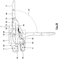
- the drive kinetics can be based on the representation according to Fig. 3 explain: As a result of the mounting of the movable gripper part 3 with the pivot bracket 10 and the gripper jaw plate 11 via the pivot bearing 13 on the fixed gripper part 2, a relative movement of the gripper jaws 6, 9 can take place. This relative movement of the jaws 6, 9 is brought about by the pivoting of the hand lever 24 relative to the fixed pliers part 2 about the pivot bearing 26.
- the hand lever 24 forms a first toggle lever 45 between the pivot bearings 26, 30.
- a second toggle lever 46 is located between the pivot bearings 17, 30 formed by the pressure lever 18.
- the pivot bearing 30 forms the knee joint of a toggle lever drive 47 formed with the toggle levers 45, 46.
- the toggle lever drive 47 converts the pivoting movement of the hand lever 24 into a pivoting movement of the movable pliers part 3 relative to the fixed pliers part 2.
- the spring device 45 is explained in more detail below: According to Fig. 4 the crimping pliers 1 is in an equilibrium position 48. In the equilibrium position 48, an opening angle of the hand lever is, for example, in the range from 40 ° to 50 °, in particular 45 ° to 48 °.
- the fixed pliers part 2 carries two stops 49, 50.
- the stops 49, 50 are designed as bolts carried in through bores of the fixed pliers part plates 4a, 4b.
- the U-shaped leaf spring or spiral spring 36 with the spring arms 51, 52 rests on the outside against an associated stop 49, 50.
- the leaf spring or spiral spring 36 and the spring arms 51, 52 cannot be pretensioned in the equilibrium position 48.
- the leaf spring or spiral spring 36 is pretensioned so that it is tensioned between the stops 49, 50.
- the movable pliers part 3 On the opposite sides of the leaf spring or spiral spring 36 (and preferably in the free end area of the spring arms 51, 52) the movable pliers part 3 carries drivers 54, 55
- the drivers 54, 55 are designed as driver pins which are held in bores in the movable pliers sub-plates 5a, 5b.
- the driver pin forming the driver 54 is multifunctional, since it is also used to fasten the jaw plate 11 to the pivot bracket 10.
- the drivers 54, 55 In the in the Fig. 4 and 5 In the equilibrium position 48 shown, the drivers 54, 55 are just resting against the leaf spring or spiral spring 36 without generating a significant contact pressure here.
- Fig. 6 and 7th show the crimping pliers 1 in a closed position 53 in which an angle of the hand levers 8, 24 is, for example, in the range from 0 ° to 10 ° (preferably in the range from 0 ° to 5 °).
- the crimping pliers 1 can automatically "spring open” with the elimination of the manual forces.
- the crimping pliers 1 automatically return from the closed position 53 to the equilibrium position 48 as a result of the action of the spring device 35.
- the crimping tool 1 is transferred from the equilibrium position 48 according to FIG Fig. 4 and 5 in a partially open position 56 according to Fig. 8 and 9 or in a (maximum) open position 57 according to Fig. 10 and 11 (whereby, for example, in the partially open position 56 the opening angle of the hand levers 8, 24 can be in the range from 60 ° to 70 °, preferably 65 ° to 68 °, and the opening angle of the hand levers 8, 24 in the open position 57 in the range from 80 ° to 100 °, preferably 85 ° to 95 °), the relative movement of the movable tong part 3 with respect to the fixed tong part 2 causes the driver 54 to move away from the spring arm 52, while the spring arm 52 is still supported on the stop 50.
- the driver 55 increases with the opening movement Force exerted on the spring arm 51.
- the increasing force results in an increasing deformation of the leaf spring or spiral spring 36 and the movement of the spring arm 51 away from the stop 49.
- the increasing loading of the leaf spring or spiral spring 36 has the consequence that the leaf spring or spiral spring 36 exerts a closing force on the tong parts 2, 3 and thus the tong jaws 6, 9.
- the closing force is aimed at restoring the equilibrium position 48.
- the crimping pliers 1 has a locking device 58 as an optional equipment variant.
- the open position 57 can be locked via the locking device 58 in such a way that the open position 57 is maintained despite the closing force of the spring device 35. Only a manual overpressure of the latched open position 57 (which results in a reduction of the latching force or complete elimination of the latching force of the latching device 58) enables the spring device 35 to automatically restore the equilibrium position 48 by means of the closing force provided by the leaf spring or spiral spring 36.
- a locking element 60 (which in particular forms a projection [or a recess]) is pressed against a counter-locking element 61 (which in particular forms a recess [or a projection]) via a locking spring 59, wherein (at least in the surrounding area of the Open position 57) a movement of the hand levers 8, 24 or the pliers jaws 6, 9 relative to one another leads to a relative movement of the latching element 60 and the counter-latching element 61.
- the detent spring 59 of the detent device 58 is formed by a detent spring arm 62 of the leaf spring or spiral spring 36 (here a longitudinal section that extends transversely from the spring arm 52 in the direction of the hand lever 24).
- the detent spring arm 62 In the free end region of the detent spring arm 62 that comes into operative connection with the hand lever 24, the detent spring arm 62 carries a pin 63 which forms the detent element 60.
- the counter-latching element 61 is formed by a recess 64 of a latching contour 65 of the hand lever 24. As it approaches the open position 57, the pin 63 slides with elastic pressure through the detent spring arm 62 along the detent contour 65.
- the pin 63 engages in the recess 64 as a result of the elastic application of the detent spring arm 62.
- the contact pressure of the latching element 60 on the counter-latching element 61 i.e. the bias of the latching spring arm 62
- the geometry of the latching contour 65 in particular the depth of the recess 64 and the inclination of the latching contour 65 in the region of the recess 64
- the closing force of the spring device 35 cannot overcome the locking of the locking device 58. Rather, for this purpose, the user must move the hand lever 24 in the closing direction in such a way that the latching element 60 can be released from the counter-latching element 61 (that is to say the pin 63 can emerge from the recess 64).
- leaf spring or spiral spring 36 is pivotably mounted on the movable pliers part 3 via a pivot pin 66.
- Fig. 12 and 13 show an example of a further embodiment of the spring device 35 encompassed by the invention.
- a coupling arm 67 of the hand lever 24 extends into the region of the movable pliers part 3.
- the free end region of the coupling arm 67 in this case is shown in FIG Fig. 12 and 13
- the equilibrium position 48 shown is caught between two compression springs 68, 69.
- the compression spring 68 forms an opening spring 70
- the compression spring 69 forms a closing spring 71.
- the latching device 58 has a latching element 60 (here a pin 63) carried by the fixed pliers part 2.
- the latching element 60 interacts with a latching contour 65 which is supported by an elastic latching spring arm 62 of the hand lever 24 and which forms the counter-latching element 61, here a recess 64.
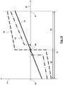
- Fig. 14 shows different characteristics 74, 75, 76 for the spring force 77 of the spring device 35 as a function of the opening angle 78 of the hand levers 8, 24.
- These characteristics 74, 75, 76 represent basic, schematic spring force curves that can be used for any configuration of the spring device 35 and the Pressing or crimping pliers 1 can be brought about.
- the origin of the abscissa corresponds to the closed position 53.
- the equilibrium position 48 is also identified here.
- the specified maximum values of the characteristics 74, 75, 76 correlate with the opening position 57.
- positive values indicate an opening force.
- Negative values on the ordinate represent a closing force of the spring device 35.
- the result is a smooth course of the spring force of the spring device 35 without a jump, a curve-shaped course also being possible depending on the spring characteristics of the spring used.
- Such a characteristic 74 can already be brought about with a single spring whose non-tensioned equilibrium position corresponds to the equilibrium position 48 and which then generates the opening force or the closing force when moving out of the equilibrium position 48 depending on the direction of movement.
- a characteristic according to the characteristic 74 can be brought about if the leaf spring or spiral spring 36 is not pretensioned in the equilibrium position 38. It should be noted, however, that, under certain circumstances, due to the different lever ratios of the drivers 54, 55, the characteristic 74 in the area of the equilibrium position 48 can also have a kink. This can also be used constructively in a targeted manner if different gradients of the characteristic 74 are desired in the partial working strokes.
- a characteristic 74 is used when, in the equilibrium position 48, the opening spring 70 and the closing spring 71 are not pretensioned and the opening spring 70 and the closing spring 71 have the same spring stiffness.
- the characteristic 75 shown in broken lines has a jump in the equilibrium position. This can be desirable if a particularly stable equilibrium position 48 is to be ensured with relatively large restoring forces in the same and / or in the two partial working strokes, the characteristic 75 should have a relatively low gradient at a high level of force.
- Such a characteristic 75 can for the embodiment according to FIG Figs. 1 to 11 be brought about by the leaf spring or spiral spring 36 being pretensioned between the stops 49, 50 in the equilibrium position 48.
- the extent of the bias specifies the level of the jump in the characteristic 75.
- the slope of the characteristic 75 in the two partial working areas is predetermined by the flexural rigidity of the leaf spring or spiral spring 36.
- a characteristic 75 can be brought about in that the opening spring 70 and the closing spring 71 are pretensioned in the equilibrium position 48 without these (as a result of the interaction between the annular shoulders 72, 73 and the stops 49, 50) exerting a force on the drivers 54, 55 produce.
- a characteristic 76 in which the exact equilibrium position 48 is not stable. Rather, the spring device does not generate any spring force in an area around the equilibrium position 48, so that this area is multistable. Only when this surrounding area is left does the illustrated characteristic 76 have a jump with an opening force or closing force that then increases further.
- Such a characteristic 76 can be brought about by, for the exemplary embodiment according to FIG Figs. 1 to 11 in the equilibrium position, the two drivers 54, 55 do not already bear against the leaf spring or spiral spring 36, as shown, but these are still spaced apart are arranged by this. The spacing of the drivers 54, 55 from the leaf spring or spiral spring 36 thus defines the area around the equilibrium position 48 for which no opening force and no closing force is generated. For the characteristic resulting therefrom, leaving the surrounding area (deviating from the characteristic 76 shown) then leads to jumps of the same height with a subsequent, same gradient of the characteristic in the partial working strokes 79, 80.
- a characteristic like the characteristic 76 shown can be brought about by the drivers 54, 55 being arranged in the equilibrium position 48 at a distance from the two compression springs 68, 69 resting on the stops 49, 50.
- the jumps have different heights when the area around the equilibrium position 48 is left. It is then also entirely possible for compression springs 68, 69 to be used with different stiffnesses, so that the characteristic 76 has different gradients in the two partial working strokes.
- a first partial working stroke 79 characterizes the operating positions of the crimping pliers 1 between the open position 57 and the equilibrium position 48
- a second partial working stroke 80 characterizes operating positions of the crimping pliers 1 between the equilibrium position 48 and the closed position 53 indicates.
- the entire stroke between the open position 57 and the closed position 53 is identified as the working stroke 81.
Landscapes
- Engineering & Computer Science (AREA)
- Mechanical Engineering (AREA)
- Manufacturing & Machinery (AREA)
- Manufacturing Of Electrical Connectors (AREA)
- Hand Tools For Fitting Together And Separating, Or Other Hand Tools (AREA)
- Gripping Jigs, Holding Jigs, And Positioning Jigs (AREA)
Priority Applications (5)
| Application Number | Priority Date | Filing Date | Title |
|---|---|---|---|
| EP18166729.6A EP3553899B1 (de) | 2018-04-11 | 2018-04-11 | Crimpwerkzeug |
| JP2019070350A JP7570082B2 (ja) | 2018-04-11 | 2019-04-02 | 圧着工具 |
| US16/377,521 US11424587B2 (en) | 2018-04-11 | 2019-04-08 | Crimping tool |
| TW108112320A TWI794467B (zh) | 2018-04-11 | 2019-04-09 | 壓接工具 |
| CN201910288303.0A CN110355724B (zh) | 2018-04-11 | 2019-04-11 | 压接工具 |
Applications Claiming Priority (1)
| Application Number | Priority Date | Filing Date | Title |
|---|---|---|---|
| EP18166729.6A EP3553899B1 (de) | 2018-04-11 | 2018-04-11 | Crimpwerkzeug |
Publications (2)
| Publication Number | Publication Date |
|---|---|
| EP3553899A1 EP3553899A1 (de) | 2019-10-16 |
| EP3553899B1 true EP3553899B1 (de) | 2021-01-27 |
Family
ID=61965853
Family Applications (1)
| Application Number | Title | Priority Date | Filing Date |
|---|---|---|---|
| EP18166729.6A Active EP3553899B1 (de) | 2018-04-11 | 2018-04-11 | Crimpwerkzeug |
Country Status (5)
| Country | Link |
|---|---|
| US (1) | US11424587B2 (enExample) |
| EP (1) | EP3553899B1 (enExample) |
| JP (1) | JP7570082B2 (enExample) |
| CN (1) | CN110355724B (enExample) |
| TW (1) | TWI794467B (enExample) |
Families Citing this family (9)
| Publication number | Priority date | Publication date | Assignee | Title |
|---|---|---|---|---|
| USD931699S1 (en) * | 2019-12-04 | 2021-09-28 | Hanlong Industrial Co., Ltd. | Crimping base |
| EP3904006B1 (de) * | 2020-04-28 | 2023-06-07 | WEZAG GmbH & Co. KG | Crimpzangen-gesenk und crimpzange |
| USD901268S1 (en) * | 2020-07-07 | 2020-11-10 | Shenzhenshi Qinbaokeji Youxiangongsi | Crimping tool |
| USD901270S1 (en) * | 2020-07-21 | 2020-11-10 | Shenzhenshi Qinbaokeji Youxiangongsi | Crimping tool |
| USD906075S1 (en) * | 2020-07-21 | 2020-12-29 | Shenzhenshi Qinbaokeji Youxiangongsi | Crimping tool |
| EP3984702B1 (de) * | 2020-10-19 | 2023-02-01 | WEZAG GmbH & Co. KG | Crimpzange und verfahren zur montage einer gesenkhälfteneinheit |
| DE102021134355A1 (de) * | 2021-12-22 | 2023-06-22 | Weidmüller Interface GmbH & Co. KG | Handbetätigbares Zangenwerkzeug |
| CN222107243U (zh) * | 2024-02-26 | 2024-12-03 | 乐清市胜搏工具有限公司 | 一种压线钳结构 |
| TWI877036B (zh) * | 2024-06-21 | 2025-03-11 | 李有信 | 具儲存置換之壓接鉗 |
Family Cites Families (30)
| Publication number | Priority date | Publication date | Assignee | Title |
|---|---|---|---|---|
| US4048877A (en) * | 1975-03-25 | 1977-09-20 | Pressmaster Ltd. | Device, particularly of the pliers or scissors type |
| GB1581725A (en) * | 1976-12-15 | 1980-12-17 | Pressmaster Ab | Appliances having cooperating working jaws |
| JPS5535753Y2 (enExample) * | 1976-05-21 | 1980-08-22 | ||
| US4381661A (en) * | 1980-03-19 | 1983-05-03 | C. A. Weidmuller Gmbh & Co. | Tool having two working jaws |
| SE9300564D0 (sv) | 1993-02-19 | 1993-02-19 | Pressmaster Tool Ab | Markeringsanordning samt pressverktyg innefattande saadan anordning |
| AU662056B2 (en) * | 1992-04-06 | 1995-08-17 | Pressmaster Tool Ab | A crimping tool |
| US5280716A (en) * | 1992-11-13 | 1994-01-25 | The Whitaker Corporation | Crimping tool |
| DE19709639A1 (de) | 1997-03-08 | 1998-09-10 | Wezag Gmbh | Zange zum Verpressen von Fassungen, Rohren, Kabelschuhen u. dgl. |
| DE19802287C1 (de) | 1998-01-22 | 1998-12-24 | Wezag Gmbh | Preßzange mit auswechselbaren Preßbacken |
| DE19834859C2 (de) | 1998-08-01 | 2001-01-11 | Wezag Gmbh | Zange zum Verpressen von Werkstücken |
| CN1147380C (zh) * | 1999-04-12 | 2004-04-28 | 奥林匹娅工业有限公司 | 改进的自动调节手钳 |
| DE19924086C2 (de) | 1999-05-26 | 2002-08-08 | Wezag Gmbh | Zange zum Verpressen von Fassungen, Rohren, Kabelschuhen und dgl. |
| DE19924087C2 (de) | 1999-05-26 | 2002-06-20 | Wezag Gmbh | Zange zum Verpressen von Fassungen, Rohren, Kabelschuhen und dgl. |
| US7444907B2 (en) * | 1999-06-15 | 2008-11-04 | I.D.L. Tech Tools, Llc | Self-adjusting pliers |
| DE29914764U1 (de) * | 1999-08-24 | 2001-01-04 | Connectool GmbH & Co., 32758 Detmold | Zange |
| DE29914763U1 (de) * | 1999-08-24 | 2001-01-04 | Connectool GmbH & Co., 32758 Detmold | Zange |
| DE19963097C5 (de) | 1999-12-24 | 2017-04-27 | Wezag Gmbh Werkzeugfabrik | Zange zum Verpressen eines Werkstücks |
| FR2807355B1 (fr) * | 2000-04-07 | 2002-08-02 | Facom | Outil de serrage, notamment pince-etau |
| US6658971B2 (en) * | 2002-02-05 | 2003-12-09 | Oberg Industries | Self-adjusting tool utilizing a cam |
| DE10346241B3 (de) | 2003-10-06 | 2004-08-12 | Wezag Gmbh Werkzeugfabrik | Zange zum Verpressen von Werkstücken |
| US20070289353A1 (en) | 2006-06-07 | 2007-12-20 | Zurn Pex, Llc | Clamping Tool |
| CN200981202Y (zh) * | 2006-11-15 | 2007-11-28 | 上海齐迈五金有限公司 | 一种双向调节锁紧机构和带有该机构的双向张夹器 |
| DE102007001235B4 (de) | 2007-01-08 | 2010-06-02 | Wezag Gmbh Werkzeugfabrik | Presszange zum Verpressen von Werkstücken |
| DE102008005472B3 (de) | 2008-01-22 | 2009-02-26 | Wezag Gmbh Werkzeugfabrik | Presszange |
| US20100218648A1 (en) * | 2009-03-02 | 2010-09-02 | Irwin Industrial Tool Company | Locking pliers with one-hand adjustment |
| US9027447B2 (en) * | 2012-01-27 | 2015-05-12 | Stanley Black & Decker, Inc. | Locking pliers with handle locking mechanism |
| EP2977146B1 (de) * | 2014-07-21 | 2020-02-12 | Wezag GmbH Werkzeugfabrik | Zangenteil |
| EP2995424B1 (de) | 2014-09-11 | 2018-12-12 | Wezag GmbH Werkzeugfabrik | Handzange |
| EP3012924B1 (de) * | 2014-10-20 | 2017-12-13 | Wezag GmbH Werkzeugfabrik | Presszange |
| EP3208044A1 (de) * | 2016-02-18 | 2017-08-23 | Wezag GmbH Werkzeugfabrik | Zange mit einem kniehebeltrieb |
-
2018
- 2018-04-11 EP EP18166729.6A patent/EP3553899B1/de active Active
-
2019
- 2019-04-02 JP JP2019070350A patent/JP7570082B2/ja active Active
- 2019-04-08 US US16/377,521 patent/US11424587B2/en active Active
- 2019-04-09 TW TW108112320A patent/TWI794467B/zh active
- 2019-04-11 CN CN201910288303.0A patent/CN110355724B/zh active Active
Non-Patent Citations (1)
| Title |
|---|
| None * |
Also Published As
| Publication number | Publication date |
|---|---|
| JP2019188591A (ja) | 2019-10-31 |
| EP3553899A1 (de) | 2019-10-16 |
| TWI794467B (zh) | 2023-03-01 |
| TW201943506A (zh) | 2019-11-16 |
| CN110355724B (zh) | 2022-05-03 |
| CN110355724A (zh) | 2019-10-22 |
| JP7570082B2 (ja) | 2024-10-21 |
| US11424587B2 (en) | 2022-08-23 |
| US20190319417A1 (en) | 2019-10-17 |
Similar Documents
| Publication | Publication Date | Title |
|---|---|---|
| EP3553899B1 (de) | Crimpwerkzeug | |
| EP3614507B1 (de) | Press- oder crimpzange | |
| EP3012923B1 (de) | Presszange | |
| EP2082837B1 (de) | Presszange | |
| EP2905848B1 (de) | Presszange | |
| DE19963097C5 (de) | Zange zum Verpressen eines Werkstücks | |
| DE10140270B4 (de) | Presszange zum Einpressen mehrerer Kerben auf dem Umfang eines Kontaktelementes | |
| EP3904007B1 (de) | Crimpzangen-gesenk und crimpzange | |
| EP0452791A1 (de) | Presswerkzeug | |
| EP3012924A1 (de) | Presszange | |
| DE202012102561U1 (de) | Crimpwerkzeug für Aderendhülsen | |
| EP3834989B1 (de) | Handzangenwerkzeug und verfahren zur montage desselben | |
| EP3984702A1 (de) | Crimpzange und verfahren zur montage einer gesenkhälfteneinheit | |
| EP3300187B1 (de) | Presswerkzeug-positionierer und presswerkzeug | |
| EP3904006B1 (de) | Crimpzangen-gesenk und crimpzange | |
| DE102008007303A1 (de) | Spreizzange | |
| DE102004045156B4 (de) | Aufsatz für ein Presswerkzeug und Verfahren zum Verpressen von rohrförmigen Werkstücken | |
| DE60008456T2 (de) | Kombination von einem Kugelgelenk und einem Dreieckslenker | |
| DE3200361A1 (de) | "haltevorrichtung fuer die rohrendstuecke in einer hydraulischen rohrendenpresse" | |
| DE69607645T2 (de) | Mehrzweckzange | |
| EP4636208A2 (de) | Beschlag zur bewegbaren lagerung eines schwenkelements | |
| EP4371705B1 (de) | Verfahren zur montage einer zangenbetätigungsbaugruppe, zangenbetätigungsbaugruppe und zange | |
| DE2916474C3 (de) | Handwerkzeug, insbesondere zum Montieren von Rohrschellen mittels eines Spreizbleches | |
| EP4371707B1 (de) | Zangenbetätigungsbaugruppe, zange und verfahren zur montage | |
| DE10243707C5 (de) | Handzange zum Verpressen von Rohrverbindungen |
Legal Events
| Date | Code | Title | Description |
|---|---|---|---|
| STAA | Information on the status of an ep patent application or granted ep patent |
Free format text: STATUS: EXAMINATION IS IN PROGRESS |
|
| PUAI | Public reference made under article 153(3) epc to a published international application that has entered the european phase |
Free format text: ORIGINAL CODE: 0009012 |
|
| 17P | Request for examination filed |
Effective date: 20181102 |
|
| AK | Designated contracting states |
Kind code of ref document: A1 Designated state(s): AL AT BE BG CH CY CZ DE DK EE ES FI FR GB GR HR HU IE IS IT LI LT LU LV MC MK MT NL NO PL PT RO RS SE SI SK SM TR |
|
| AX | Request for extension of the european patent |
Extension state: BA ME |
|
| RBV | Designated contracting states (corrected) |
Designated state(s): AL AT BE BG CH CY CZ DE DK EE ES FI FR GB GR HR HU IE IS IT LI LT LU LV MC MK MT NL NO PL PT RO RS SE SI SK SM TR |
|
| GRAP | Despatch of communication of intention to grant a patent |
Free format text: ORIGINAL CODE: EPIDOSNIGR1 |
|
| STAA | Information on the status of an ep patent application or granted ep patent |
Free format text: STATUS: GRANT OF PATENT IS INTENDED |
|
| RIC1 | Information provided on ipc code assigned before grant |
Ipc: B25B 7/16 20060101ALI20200824BHEP Ipc: B25B 27/14 20060101ALI20200824BHEP Ipc: H01R 43/042 20060101AFI20200824BHEP |
|
| INTG | Intention to grant announced |
Effective date: 20200911 |
|
| GRAS | Grant fee paid |
Free format text: ORIGINAL CODE: EPIDOSNIGR3 |
|
| GRAA | (expected) grant |
Free format text: ORIGINAL CODE: 0009210 |
|
| STAA | Information on the status of an ep patent application or granted ep patent |
Free format text: STATUS: THE PATENT HAS BEEN GRANTED |
|
| AK | Designated contracting states |
Kind code of ref document: B1 Designated state(s): AL AT BE BG CH CY CZ DE DK EE ES FI FR GB GR HR HU IE IS IT LI LT LU LV MC MK MT NL NO PL PT RO RS SE SI SK SM TR |
|
| REG | Reference to a national code |
Ref country code: GB Ref legal event code: FG4D Free format text: NOT ENGLISH |
|
| REG | Reference to a national code |
Ref country code: CH Ref legal event code: EP |
|
| REG | Reference to a national code |
Ref country code: AT Ref legal event code: REF Ref document number: 1359189 Country of ref document: AT Kind code of ref document: T Effective date: 20210215 |
|
| REG | Reference to a national code |
Ref country code: IE Ref legal event code: FG4D Free format text: LANGUAGE OF EP DOCUMENT: GERMAN |
|
| REG | Reference to a national code |
Ref country code: DE Ref legal event code: R096 Ref document number: 502018003767 Country of ref document: DE |
|
| REG | Reference to a national code |
Ref country code: DE Ref legal event code: R082 Ref document number: 502018003767 Country of ref document: DE Representative=s name: REHBERG HUEPPE + PARTNER PATENTANWAELTE PARTG , DE Ref country code: DE Ref legal event code: R081 Ref document number: 502018003767 Country of ref document: DE Owner name: WEZAG GMBH & CO. KG, DE Free format text: FORMER OWNER: WEZAG GMBH WERKZEUGFABRIK, 35260 STADTALLENDORF, DE |
|
| REG | Reference to a national code |
Ref country code: SE Ref legal event code: TRGR |
|
| REG | Reference to a national code |
Ref country code: NL Ref legal event code: MP Effective date: 20210127 |
|
| REG | Reference to a national code |
Ref country code: LT Ref legal event code: MG9D |
|
| PG25 | Lapsed in a contracting state [announced via postgrant information from national office to epo] |
Ref country code: NO Free format text: LAPSE BECAUSE OF FAILURE TO SUBMIT A TRANSLATION OF THE DESCRIPTION OR TO PAY THE FEE WITHIN THE PRESCRIBED TIME-LIMIT Effective date: 20210427 Ref country code: PT Free format text: LAPSE BECAUSE OF FAILURE TO SUBMIT A TRANSLATION OF THE DESCRIPTION OR TO PAY THE FEE WITHIN THE PRESCRIBED TIME-LIMIT Effective date: 20210527 Ref country code: LT Free format text: LAPSE BECAUSE OF FAILURE TO SUBMIT A TRANSLATION OF THE DESCRIPTION OR TO PAY THE FEE WITHIN THE PRESCRIBED TIME-LIMIT Effective date: 20210127 Ref country code: GR Free format text: LAPSE BECAUSE OF FAILURE TO SUBMIT A TRANSLATION OF THE DESCRIPTION OR TO PAY THE FEE WITHIN THE PRESCRIBED TIME-LIMIT Effective date: 20210428 Ref country code: FI Free format text: LAPSE BECAUSE OF FAILURE TO SUBMIT A TRANSLATION OF THE DESCRIPTION OR TO PAY THE FEE WITHIN THE PRESCRIBED TIME-LIMIT Effective date: 20210127 Ref country code: HR Free format text: LAPSE BECAUSE OF FAILURE TO SUBMIT A TRANSLATION OF THE DESCRIPTION OR TO PAY THE FEE WITHIN THE PRESCRIBED TIME-LIMIT Effective date: 20210127 Ref country code: BG Free format text: LAPSE BECAUSE OF FAILURE TO SUBMIT A TRANSLATION OF THE DESCRIPTION OR TO PAY THE FEE WITHIN THE PRESCRIBED TIME-LIMIT Effective date: 20210427 |
|
| PG25 | Lapsed in a contracting state [announced via postgrant information from national office to epo] |
Ref country code: RS Free format text: LAPSE BECAUSE OF FAILURE TO SUBMIT A TRANSLATION OF THE DESCRIPTION OR TO PAY THE FEE WITHIN THE PRESCRIBED TIME-LIMIT Effective date: 20210127 Ref country code: PL Free format text: LAPSE BECAUSE OF FAILURE TO SUBMIT A TRANSLATION OF THE DESCRIPTION OR TO PAY THE FEE WITHIN THE PRESCRIBED TIME-LIMIT Effective date: 20210127 Ref country code: LV Free format text: LAPSE BECAUSE OF FAILURE TO SUBMIT A TRANSLATION OF THE DESCRIPTION OR TO PAY THE FEE WITHIN THE PRESCRIBED TIME-LIMIT Effective date: 20210127 |
|
| PG25 | Lapsed in a contracting state [announced via postgrant information from national office to epo] |
Ref country code: IS Free format text: LAPSE BECAUSE OF FAILURE TO SUBMIT A TRANSLATION OF THE DESCRIPTION OR TO PAY THE FEE WITHIN THE PRESCRIBED TIME-LIMIT Effective date: 20210527 |
|
| REG | Reference to a national code |
Ref country code: DE Ref legal event code: R097 Ref document number: 502018003767 Country of ref document: DE |
|
| PG25 | Lapsed in a contracting state [announced via postgrant information from national office to epo] |
Ref country code: SM Free format text: LAPSE BECAUSE OF FAILURE TO SUBMIT A TRANSLATION OF THE DESCRIPTION OR TO PAY THE FEE WITHIN THE PRESCRIBED TIME-LIMIT Effective date: 20210127 Ref country code: CZ Free format text: LAPSE BECAUSE OF FAILURE TO SUBMIT A TRANSLATION OF THE DESCRIPTION OR TO PAY THE FEE WITHIN THE PRESCRIBED TIME-LIMIT Effective date: 20210127 Ref country code: EE Free format text: LAPSE BECAUSE OF FAILURE TO SUBMIT A TRANSLATION OF THE DESCRIPTION OR TO PAY THE FEE WITHIN THE PRESCRIBED TIME-LIMIT Effective date: 20210127 |
|
| PG25 | Lapsed in a contracting state [announced via postgrant information from national office to epo] |
Ref country code: RO Free format text: LAPSE BECAUSE OF FAILURE TO SUBMIT A TRANSLATION OF THE DESCRIPTION OR TO PAY THE FEE WITHIN THE PRESCRIBED TIME-LIMIT Effective date: 20210127 Ref country code: DK Free format text: LAPSE BECAUSE OF FAILURE TO SUBMIT A TRANSLATION OF THE DESCRIPTION OR TO PAY THE FEE WITHIN THE PRESCRIBED TIME-LIMIT Effective date: 20210127 Ref country code: SK Free format text: LAPSE BECAUSE OF FAILURE TO SUBMIT A TRANSLATION OF THE DESCRIPTION OR TO PAY THE FEE WITHIN THE PRESCRIBED TIME-LIMIT Effective date: 20210127 Ref country code: MC Free format text: LAPSE BECAUSE OF FAILURE TO SUBMIT A TRANSLATION OF THE DESCRIPTION OR TO PAY THE FEE WITHIN THE PRESCRIBED TIME-LIMIT Effective date: 20210127 |
|
| PLBE | No opposition filed within time limit |
Free format text: ORIGINAL CODE: 0009261 |
|
| STAA | Information on the status of an ep patent application or granted ep patent |
Free format text: STATUS: NO OPPOSITION FILED WITHIN TIME LIMIT |
|
| PG25 | Lapsed in a contracting state [announced via postgrant information from national office to epo] |
Ref country code: LU Free format text: LAPSE BECAUSE OF NON-PAYMENT OF DUE FEES Effective date: 20210411 |
|
| 26N | No opposition filed |
Effective date: 20211028 |
|
| REG | Reference to a national code |
Ref country code: BE Ref legal event code: MM Effective date: 20210430 |
|
| PG25 | Lapsed in a contracting state [announced via postgrant information from national office to epo] |
Ref country code: FR Free format text: LAPSE BECAUSE OF NON-PAYMENT OF DUE FEES Effective date: 20210430 Ref country code: ES Free format text: LAPSE BECAUSE OF FAILURE TO SUBMIT A TRANSLATION OF THE DESCRIPTION OR TO PAY THE FEE WITHIN THE PRESCRIBED TIME-LIMIT Effective date: 20210127 Ref country code: LI Free format text: LAPSE BECAUSE OF NON-PAYMENT OF DUE FEES Effective date: 20210430 Ref country code: AL Free format text: LAPSE BECAUSE OF FAILURE TO SUBMIT A TRANSLATION OF THE DESCRIPTION OR TO PAY THE FEE WITHIN THE PRESCRIBED TIME-LIMIT Effective date: 20210127 Ref country code: CH Free format text: LAPSE BECAUSE OF NON-PAYMENT OF DUE FEES Effective date: 20210430 |
|
| PG25 | Lapsed in a contracting state [announced via postgrant information from national office to epo] |
Ref country code: SI Free format text: LAPSE BECAUSE OF FAILURE TO SUBMIT A TRANSLATION OF THE DESCRIPTION OR TO PAY THE FEE WITHIN THE PRESCRIBED TIME-LIMIT Effective date: 20210127 |
|
| PG25 | Lapsed in a contracting state [announced via postgrant information from national office to epo] |
Ref country code: IT Free format text: LAPSE BECAUSE OF FAILURE TO SUBMIT A TRANSLATION OF THE DESCRIPTION OR TO PAY THE FEE WITHIN THE PRESCRIBED TIME-LIMIT Effective date: 20210127 Ref country code: IE Free format text: LAPSE BECAUSE OF NON-PAYMENT OF DUE FEES Effective date: 20210411 |
|
| PG25 | Lapsed in a contracting state [announced via postgrant information from national office to epo] |
Ref country code: IS Free format text: LAPSE BECAUSE OF FAILURE TO SUBMIT A TRANSLATION OF THE DESCRIPTION OR TO PAY THE FEE WITHIN THE PRESCRIBED TIME-LIMIT Effective date: 20210527 |
|
| PG25 | Lapsed in a contracting state [announced via postgrant information from national office to epo] |
Ref country code: BE Free format text: LAPSE BECAUSE OF NON-PAYMENT OF DUE FEES Effective date: 20210430 |
|
| GBPC | Gb: european patent ceased through non-payment of renewal fee |
Effective date: 20220411 |
|
| PG25 | Lapsed in a contracting state [announced via postgrant information from national office to epo] |
Ref country code: GB Free format text: LAPSE BECAUSE OF NON-PAYMENT OF DUE FEES Effective date: 20220411 |
|
| PG25 | Lapsed in a contracting state [announced via postgrant information from national office to epo] |
Ref country code: NL Free format text: LAPSE BECAUSE OF NON-PAYMENT OF DUE FEES Effective date: 20210127 Ref country code: CY Free format text: LAPSE BECAUSE OF FAILURE TO SUBMIT A TRANSLATION OF THE DESCRIPTION OR TO PAY THE FEE WITHIN THE PRESCRIBED TIME-LIMIT Effective date: 20210127 |
|
| P01 | Opt-out of the competence of the unified patent court (upc) registered |
Effective date: 20230529 |
|
| PG25 | Lapsed in a contracting state [announced via postgrant information from national office to epo] |
Ref country code: HU Free format text: LAPSE BECAUSE OF FAILURE TO SUBMIT A TRANSLATION OF THE DESCRIPTION OR TO PAY THE FEE WITHIN THE PRESCRIBED TIME-LIMIT; INVALID AB INITIO Effective date: 20180411 |
|
| PG25 | Lapsed in a contracting state [announced via postgrant information from national office to epo] |
Ref country code: MK Free format text: LAPSE BECAUSE OF FAILURE TO SUBMIT A TRANSLATION OF THE DESCRIPTION OR TO PAY THE FEE WITHIN THE PRESCRIBED TIME-LIMIT Effective date: 20210127 |
|
| REG | Reference to a national code |
Ref country code: AT Ref legal event code: MM01 Ref document number: 1359189 Country of ref document: AT Kind code of ref document: T Effective date: 20230411 |
|
| PG25 | Lapsed in a contracting state [announced via postgrant information from national office to epo] |
Ref country code: AT Free format text: LAPSE BECAUSE OF NON-PAYMENT OF DUE FEES Effective date: 20230411 |
|
| PG25 | Lapsed in a contracting state [announced via postgrant information from national office to epo] |
Ref country code: AT Free format text: LAPSE BECAUSE OF NON-PAYMENT OF DUE FEES Effective date: 20230411 |
|
| PG25 | Lapsed in a contracting state [announced via postgrant information from national office to epo] |
Ref country code: MT Free format text: LAPSE BECAUSE OF FAILURE TO SUBMIT A TRANSLATION OF THE DESCRIPTION OR TO PAY THE FEE WITHIN THE PRESCRIBED TIME-LIMIT Effective date: 20210127 |
|
| PGFP | Annual fee paid to national office [announced via postgrant information from national office to epo] |
Ref country code: SE Payment date: 20250311 Year of fee payment: 8 |
|
| PGFP | Annual fee paid to national office [announced via postgrant information from national office to epo] |
Ref country code: DE Payment date: 20250212 Year of fee payment: 8 |
|
| PG25 | Lapsed in a contracting state [announced via postgrant information from national office to epo] |
Ref country code: TR Free format text: LAPSE BECAUSE OF FAILURE TO SUBMIT A TRANSLATION OF THE DESCRIPTION OR TO PAY THE FEE WITHIN THE PRESCRIBED TIME-LIMIT Effective date: 20210127 |