EP3553899B1 - Crimping tool - Google Patents
Crimping tool Download PDFInfo
- Publication number
- EP3553899B1 EP3553899B1 EP18166729.6A EP18166729A EP3553899B1 EP 3553899 B1 EP3553899 B1 EP 3553899B1 EP 18166729 A EP18166729 A EP 18166729A EP 3553899 B1 EP3553899 B1 EP 3553899B1
- Authority
- EP
- European Patent Office
- Prior art keywords
- pliers
- spring
- crimping
- working stroke
- pressing
- Prior art date
- Legal status (The legal status is an assumption and is not a legal conclusion. Google has not performed a legal analysis and makes no representation as to the accuracy of the status listed.)
- Active
Links
Images


Classifications
-
- B—PERFORMING OPERATIONS; TRANSPORTING
- B25—HAND TOOLS; PORTABLE POWER-DRIVEN TOOLS; MANIPULATORS
- B25B—TOOLS OR BENCH DEVICES NOT OTHERWISE PROVIDED FOR, FOR FASTENING, CONNECTING, DISENGAGING OR HOLDING
- B25B27/00—Hand tools, specially adapted for fitting together or separating parts or objects whether or not involving some deformation, not otherwise provided for
- B25B27/14—Hand tools, specially adapted for fitting together or separating parts or objects whether or not involving some deformation, not otherwise provided for for assembling objects other than by press fit or detaching same
- B25B27/146—Clip clamping hand tools
-
- H—ELECTRICITY
- H01—ELECTRIC ELEMENTS
- H01R—ELECTRICALLY-CONDUCTIVE CONNECTIONS; STRUCTURAL ASSOCIATIONS OF A PLURALITY OF MUTUALLY-INSULATED ELECTRICAL CONNECTING ELEMENTS; COUPLING DEVICES; CURRENT COLLECTORS
- H01R43/00—Apparatus or processes specially adapted for manufacturing, assembling, maintaining, or repairing of line connectors or current collectors or for joining electric conductors
- H01R43/04—Apparatus or processes specially adapted for manufacturing, assembling, maintaining, or repairing of line connectors or current collectors or for joining electric conductors for forming connections by deformation, e.g. crimping tool
- H01R43/042—Hand tools for crimping
-
- B—PERFORMING OPERATIONS; TRANSPORTING
- B25—HAND TOOLS; PORTABLE POWER-DRIVEN TOOLS; MANIPULATORS
- B25B—TOOLS OR BENCH DEVICES NOT OTHERWISE PROVIDED FOR, FOR FASTENING, CONNECTING, DISENGAGING OR HOLDING
- B25B27/00—Hand tools, specially adapted for fitting together or separating parts or objects whether or not involving some deformation, not otherwise provided for
- B25B27/14—Hand tools, specially adapted for fitting together or separating parts or objects whether or not involving some deformation, not otherwise provided for for assembling objects other than by press fit or detaching same
-
- B—PERFORMING OPERATIONS; TRANSPORTING
- B25—HAND TOOLS; PORTABLE POWER-DRIVEN TOOLS; MANIPULATORS
- B25B—TOOLS OR BENCH DEVICES NOT OTHERWISE PROVIDED FOR, FOR FASTENING, CONNECTING, DISENGAGING OR HOLDING
- B25B7/00—Pliers; Other hand-held gripping tools with jaws on pivoted limbs; Details applicable generally to pivoted-limb hand tools
- B25B7/14—Locking means
- B25B7/16—Locking means combined with means for tightening the operating arms of jaws
-
- H—ELECTRICITY
- H01—ELECTRIC ELEMENTS
- H01R—ELECTRICALLY-CONDUCTIVE CONNECTIONS; STRUCTURAL ASSOCIATIONS OF A PLURALITY OF MUTUALLY-INSULATED ELECTRICAL CONNECTING ELEMENTS; COUPLING DEVICES; CURRENT COLLECTORS
- H01R43/00—Apparatus or processes specially adapted for manufacturing, assembling, maintaining, or repairing of line connectors or current collectors or for joining electric conductors
- H01R43/04—Apparatus or processes specially adapted for manufacturing, assembling, maintaining, or repairing of line connectors or current collectors or for joining electric conductors for forming connections by deformation, e.g. crimping tool
- H01R43/042—Hand tools for crimping
- H01R43/0425—Hand tools for crimping with mandrels actuated in axial direction to the wire
-
- Y—GENERAL TAGGING OF NEW TECHNOLOGICAL DEVELOPMENTS; GENERAL TAGGING OF CROSS-SECTIONAL TECHNOLOGIES SPANNING OVER SEVERAL SECTIONS OF THE IPC; TECHNICAL SUBJECTS COVERED BY FORMER USPC CROSS-REFERENCE ART COLLECTIONS [XRACs] AND DIGESTS
- Y10—TECHNICAL SUBJECTS COVERED BY FORMER USPC
- Y10T—TECHNICAL SUBJECTS COVERED BY FORMER US CLASSIFICATION
- Y10T29/00—Metal working
- Y10T29/53—Means to assemble or disassemble
- Y10T29/5313—Means to assemble electrical device
- Y10T29/532—Conductor
- Y10T29/53209—Terminal or connector
- Y10T29/53213—Assembled to wire-type conductor
- Y10T29/53222—Means comprising hand-manipulatable implement
- Y10T29/53226—Fastening by deformation
Definitions
- the present invention relates to crimping pliers.
- the pressing or crimping pliers can be used to manually actuate hand levers to press or crimp a workpiece.
- the crimp produced for a closed crimp can be, for example, a hexagonal or hexagonal crimp, a square crimp, a B crimp, a trapezoid crimp, a modified trapezoid crimp, an oval crimp, a mandrel crimp or a two-mandrel crimp.
- An open crimp can be designed, for example, as a V crimp or B crimp, as a roll crimp or as a double roll crimp.
- a generic crimping tool is preferably used for the mechanical fluid-tight connection in fluid technology, for example to connect pipes to one another or to fluidic connectors.
- plastic deformation of the pipes to be connected or a so-called fitting ensuring the mechanical connection and the fluid-tight seal takes place by means of the pressing tongs.
- Exemplary embodiments of a generic pressing tongs can be found in the publications DE 197 09 639 A1 , DE 198 34 859 C2 , DE 199 24 086 C2 , DE 199 24 087 C2 , DE 199 63 097 C1 , DE 103 46 241 B3 , DE 10 2007 001 235 B4 , DE 10 2008 005 472 B3 , EP 3 208 044 A1 , EP 2 995 424 A1 can be removed.
- U.S. 5,280,716 A discloses crimping pliers in which a fixed pliers part forms a fixed hand lever and a fixed pliers jaw.
- a movable pliers jaw is mounted on the fixed pliers part via a pivot bearing.
- a movable hand lever is articulated on the movable pliers jaw.
- the movable hand lever is additionally supported on the fixed hand lever via a pressure lever.
- a first spring is articulated with a spring base between the pivot bearing and the articulation of the pressure lever on the movable hand lever, while the other spring foot point is articulated on the fixed hand lever. The first spring acts on the movable hand lever in the opening direction.
- a second spring which is designed as a torsion leg spring, acts on the pressure lever in the opening direction.
- the crimping pliers assume an open position without the hand of the user acting on the hand lever, while an at least partial closure of the hand lever requires the user to apply closing forces to the hand lever.
- the bolt via which the pressure lever is articulated to the movable hand lever, is guided in an elongated hole, with which it can assume a first position and a second position.
- the bolt From the open position to a partially closed position, the bolt assumes the first position, in which the drive connection designed as a toggle lever drive has a relatively large transmission ratio, with which small forces are generated in the area of the pincer jaws, but large closing angles of the pincer jaws can be brought about.
- the partially closed position for which the dies held on the pliers jaws are just resting on the outer surface of the workpiece, the bolt is automatically transferred to the second position due to the alignment of the elongated hole, which means that the drive connection is switched to a smaller translation, with which then larger forces can be brought about on the pliers jaws.
- Intermediate locking positions can be secured using a compulsory lock.
- Another crimping tool is off WO 93/19897 A1 known.
- the invention is based on the object of proposing manually operated crimping or crimping pliers which are improved in terms of force ratios, ease of use and safety.
- conflicting objectives cannot be resolved.
- the manufacturer of the crimping or crimping pliers had to decide between a spring acting in the opening direction or a spring acting in the closing direction.
- pressing or crimping pliers which have two pliers jaws (supporting or forming dies).
- the pliers jaws are drive-connected via a suitable drive mechanism with two hand levers.
- a working stroke of the tong jaws from an open position of the tong jaws into a closed position of the tong jaws can be brought about by relative movement of the hand lever.
- the working stroke can have an "idle stroke" in which the dies are first placed against the workpiece, as well as a press or crimp stroke in which the workpiece is pressed or crimped between the dies.
- At least one spring device is used in the pressing or crimping pliers according to the invention.
- the at least one spring device is designed in a special way within the scope of the invention and is integrated into the force flow: the at least one spring device initially ensures an equilibrium position. In the equilibrium position, the spring device does not exert any force on the jaws. In the event that a single spring device is used, this spring device is not tensioned in the equilibrium position (or is only tensioned to such a small extent that friction or any other resistance in the crimping pliers cannot be overcome). In the event that several spring devices are used, none of them can be tensioned or the action of the tensioned spring devices cancels one another.
- the said equilibrium position the pincer jaw is arranged between the open position and the closed position of the pincer jaws (for example between 20% to 80% or 30% to 60% of the working stroke).
- the equilibrium position divides the working stroke into a first partial working stroke, which is arranged between the open position and the equilibrium position of the gripper jaws, and a second partial working stroke, which is arranged between the equilibrium position and the closed position.
- the at least one spring device exerts a closing force on the gripper jaws.
- the spring device exerts an opening force on the jaws in the second partial working stroke.
- the spring device preferably generates a non-linear characteristic of the spring force.
- the non-linear characteristic of the spring force exhibits a kink and / or a jump, particularly in the equilibrium position or between the two partial working strokes.
- the spring device can have one or more springs.
- the at least one spring can be made from any material (for example metal, plastic, an elastomer material) and also from a composite material. It can be a compression spring, tension spring, an angle spring, a torsion spring or a spring of any other type. If several springs are used, they can be arranged in mechanical series connection or parallel connection and / or integrated into the force flow at different points. It is also possible that one spring acts in the opening direction and another spring acts in the closing direction.
- the spring device preferably generates a non-linear characteristic which, in particular, has a kink and / or a jump in the equilibrium position or between the two partial working strokes.
- the spring device has a closing spring and an opening spring.
- the closing spring generates the closing force in the first partial working stroke
- the opening spring generates the opening force in the second partial working stroke. It is possible here that the opening spring is decoupled from the drive connection in the first partial working stroke, while the closing spring can be decoupled from the drive connection in the second partial working stroke.
- the spring device (preferably exclusively) has a spring.
- This spring is then used multifunctionally in that it generates the closing force in the first partial working stroke as well as generating the opening force in the second partial working stroke.
- a spring of the spring device to be coupled to the movement of the tong jaws over the entire working stroke. In this case changed the loading of the spring over the entire working stroke.
- the pressing or crimping pliers have at least one stop.
- the stop specifies an extreme deflection of a spring base point of the spring device, which is preferably a minimal deflection.
- a driver is available for this embodiment of the pressing or crimping pliers. In the partial working stroke, the driver takes the spring base point of the spring device with it and moves it away from the stop, which then changes the action on the spring.
- the spring base of the spring device preferably remains at the stop in the other partial working stroke. Thus, the application of the spring does not change for the other partial working stroke.
- the stop specifies a minimal application of pressure to the compression spring.
- the compressive force in the compression spring increases.
- the increasing compressive force of the compression spring can then be used to generate the closing force or the opening force.
- the stop provides a minimum tensile force in the tension spring, while the deflection and the tensile force increase as the driver continues to act on the tension spring.
- each spring can be supported on an associated stop in the equilibrium position.
- a driver moves the spring base point of a spring away from the assigned stop, while the other spring base point remains at the assigned stop.
- the other driver then moves the spring base of the other spring away from the associated stop, while in this case the spring base of the first-mentioned spring continues to be supported on the stop.
- the at least one stop and the at least one driver can be arranged on any components of the crimping or crimping pliers, as long as one during the working stroke Relative movement of the components on which the stop and the driver are arranged takes place.
- the driver it is possible for the driver to be supported on a hand lever, while the assigned stop is attached to a (preferably moved) pliers jaw.
- the stop is attached to a pliers head or carried by this, while the driver is attached to or carried by a pliers jaw moved over the working stroke with respect to the pliers head. If there are two stops and drivers, this can also apply to both stops and drivers.
- the at least one spring of the spring device can be designed as desired.
- a single spring is used, which is designed as a U-shaped spiral spring or leaf spring.
- Such a spiral spring or leaf spring represents a structurally simple spring with a long service life, in which the cross sections of the spiral spring or leaf spring and possibly the cross-sectional profile, the course of the longitudinal axis of the spiral spring or leaf spring, the material used and the effective length of the spiral spring or leaf spring the stiffness and any non-linearity of the stiffness behavior can be specified constructively. Because the spiral spring or leaf spring is U-shaped, the different spring arms of the U can be used to configure the rigidity.
- a particularly good integration of the U-shaped spiral spring or leaf spring into the pressing or crimping pliers can result for an embodiment of the invention if the spring arms of the U-shaped spiral spring or leaf spring extend in the direction of a longitudinal axis of the pliers head or in the direction of the closed hand lever .
- the crimping or crimping tool is equipped with an automatic lock.
- a compulsory lock secures a partial closed position of the jaws against an opening that has been reached.
- a partial closed position is maintained even if the manual forces acting on the hand lever are temporarily eliminated.
- Such a compulsory lock enables the jaws to be opened only when the working stroke has been completed. With these measures, the process reliability can be increased.
- the spring device automatically moves the gripper jaws back into the equilibrium position when the working stroke is fully completed (that is, when the automatic locking mechanism is unlocked).
- the automatic locking mechanism is designed in such a way that it is only effective in the second partial working stroke (or only in an end partial section of the same), so that this does not hinder the desired effect of the spring device in the first partial working stroke.
- the open position in which the workpiece can be inserted into the jaws of the pliers
- the open position is only maintained in view of the action of the spring device if the user applies opening forces to the hand lever or the pliers jaws, which the force of the action of the pliers jaws counteract by the spring device.
- a latching device or a locking device is available for this suggestion. The latching device or locking device secures the open position so that the open position can be automatically maintained despite the closing force of the spring device acting in the open position.
- a locking device is understood to mean, in particular, a device that effects a locking that leads to a locking force that is greater than the closing force generated by the spring device.
- a locking device is understood to mean in particular a device in which an open position is locked in such a way that it cannot be left simply by applying closing forces (for example via the hand lever or by closing forces applied directly to the pliers jaws). Rather, manual actuation of a locking element is required, which then releases the locking so that the spring device can then bring the pliers jaws back into the equilibrium position or bring the dies to the workpiece.
- the spring or a spring of the spring device is multifunctional in that this spring generates the opening force and / or the closing force on the one hand. In addition, this spring also generates a locking force of the locking device or a locking force of the locking device.
- a spring arm of the U-shaped leaf spring or spiral spring carries a latching spring arm of the latching device.
- the detent spring arm resiliently forms a detent element or carries it.
- the latching element interacts with a latching counter-latching element, with a relative movement of the counter-latching element relative to the latching element taking place over the working stroke and in particular in the area surrounding the open position.
- a fixed pliers part (which can be made in one or more pieces) forms a fixed pliers jaw and a fixed hand lever out.
- a movable pliers part (which can also be designed in one or more pieces) then forms a movable pliers jaw.
- the movable tong part is pivotably articulated to the fixed tong part via a pivot bearing.
- a movable hand lever is pivotably articulated to the fixed pliers part via a pivot bearing.
- the movable hand lever is then connected to the movable pliers part via a drive connection (in particular a pressure lever drive or a toggle lever drive).
- the movable hand lever forms the counter-locking element in this case.
- the pivot bearing via which the movable pliers part is pivotably articulated to the fixed pliers part, is arranged in the half of the longitudinal extension of the fixed pliers part facing away from the pliers head (the pivot bearing in this case, for example Can be located at a distance from the front end region of the long head which is more than 55%, more than 60%, more than 65%, more than 70% or even more than 75% of the length of the fixed pliers part).
- the pivot bearing away from the pliers head the pivot radius of the dies can also be increased.
- the swivel angle of the dies can be reduced over the working stroke in this way. Too much pivoting of the dies relative to one another has proven to be negative for the pressing or crimping result.
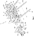
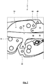
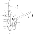
- Figs. 1 to 11 show a crimping tool 1 in panel construction.
- the crimping pliers 1 has a fixed pliers part 2 and a movable pliers part 3.
- the fixed pliers part 2 has two fixed ones
- the movable tong part 3 has two movable tong part plates 5a, 5b.
- the fixed pliers part 2 has a fixed pliers jaw 6, a connection area 7 and a fixed hand lever 8.
- the fixed pliers part plate 4a forms the fixed pliers jaw 6, the connection area 7 and the fixed hand lever 8.
- the fixed pliers part plate 4b only forms the fixed pliers jaw 6 and the connecting area 7.
- the movable tong part 3 has a movable tong jaw 9.
- the movable tong jaw 9 is held on a pivot bracket 10.
- the movable tong part plates 5a, 5b are designed in two parts with tong jaw plates 11a, 11b and pivoting support plates 12a, 12b.
- the movable tong part 3 is mounted on the fixed tong part 2 via a pivot bearing 13 so as to be pivotable about a pivot axis 14. In the illustrated embodiment, this is done by a pivot pin 15.
- the pivot pin 15 extends through through bores 16a, 16b, 16c, 16d of the movable pliers part plates 5a, 5b and fixed pliers part plates 4a, 4b, which allow pivoting.
- the two movable pliers part plates 5a, 5b are received between the fixed pliers part plates 4a, 4b.
- the tong jaw plates 11a, 11b are attached to the pivoting support plates 12a, 12b and held thereon such that the tong jaw plates 11a, 11b extend in the parallel planes given by the fixed tong part plates 4a, 4b and move in these planes during the pivoting.
- a pressure lever 18 (which is formed here with two pressure lever plates 19a, 19b) is articulated to the movable pliers part 3 via a pivot bearing 17.
- the pivot bearing 17 is formed with a pivot pin 20.
- the pivot bolt 20 is received in through bores 21a, 21b, 21c, 21d of the pressure lever plate 19b, the pivot support plate 12b, the pivot support plate 12a and the pressure lever plate 19a. In this way, a pivot axis 22 of the pivot bearing 17 is predetermined.
- the two pressure lever plates 19 are not arranged between the fixed pliers part plates 4a, 4b, but outside the same.
- the pivot pin 20 extends through elongated holes 23a, 23b of the fixed pliers part plates 4a, 4b.
- the elongated holes 23a, 23b are shaped and arranged in such a way that the fixed tong part plates 4a, 4b do not hinder the movement of the pivot pin 20 with the pivoting of the movable tong part 3.
- a movable hand lever 24 (which here has two movable hand lever plates 25a, 25b) is mounted on the fixed pliers part 2 such that it can pivot via a pivot bearing 26 with a pivot axis 27.
- the fixed pliers part plate 4b, the hand lever plate 25b, the hand lever plate 25a and the fixed pliers part plate 4a have through bores 28a, 28b, 28c, 28d.
- a pivot bolt 29 extends through the through bores 28a, 28b, 28c, 28d. The pivot bolt 29 enables a relative pivoting movement of the movable hand lever 24 with respect to the fixed pliers part 2.
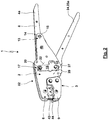
- the pressure lever 18 is pivotably connected to the hand lever 24 via a pivot bearing 30.
- the pressure lever plates 19a, 19b have through bores 31a, 31d.
- the hand lever plates 25a, 25b have through bores 31b, 31c adjacent to the through bores 28b, 28c.
- a pivot pin 32 which enables a pivoting movement, extends through the through bores 31b, 31c. Since for this purpose the pivot pin 32 has to pass through the fixed tong part plates 4a, 4b, the fixed tong part plates 4a, 4b have elongated holes 33a, 33b.
- the elongated holes 33a, 33b ensure that the degree of freedom of movement of the pivot pin 32 is not hindered.
- a spring 34 which is part of a spring device 35, is arranged in this central pliers plate plane.
- the spring 34 is designed as a U-shaped leaf spring or spiral spring 36.
- a compulsory lock 37 is used in the crimping tool 1.
- the automatic locking mechanism 37 has a locking pawl 38.
- the pawl is carried by a pawl shaft 39 here.
- the pawl shaft 39 is rotatably mounted on the pressure lever plates 19a, 19b.
- the pawl shaft 39 extends, without restricting the degree of freedom of movement, through through recesses 40a, 40b of the fixed pliers part plates 4a, 4b.
- the hand lever 24 forms a locking toothing 41 in the area of its peripheral surface.
- the pawl 38 slides like a ratchet as a result of being acted upon by a spring 42 along the locking toothing 41 reverse direction is excluded.
- the pawl 38 has passed the locking teeth 41.
- the pawl 38 as a result of the tensile force generated by the spring 42 "fold over". After folding over, the pawl 38 can then slide along the locking toothing 41 during an opening movement.
- the tong jaws 6, 9 each carry a die 43, 44 in an exchangeable manner.
- a connection of the tong jaws 6, 9 with the dies 43, 44 is preferably used, as is the case in the patent DE 198 02 287 C1 is described.
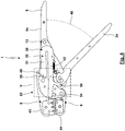
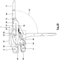
- the drive kinetics can be based on the representation according to Fig. 3 explain: As a result of the mounting of the movable gripper part 3 with the pivot bracket 10 and the gripper jaw plate 11 via the pivot bearing 13 on the fixed gripper part 2, a relative movement of the gripper jaws 6, 9 can take place. This relative movement of the jaws 6, 9 is brought about by the pivoting of the hand lever 24 relative to the fixed pliers part 2 about the pivot bearing 26.
- the hand lever 24 forms a first toggle lever 45 between the pivot bearings 26, 30.
- a second toggle lever 46 is located between the pivot bearings 17, 30 formed by the pressure lever 18.
- the pivot bearing 30 forms the knee joint of a toggle lever drive 47 formed with the toggle levers 45, 46.
- the toggle lever drive 47 converts the pivoting movement of the hand lever 24 into a pivoting movement of the movable pliers part 3 relative to the fixed pliers part 2.
- the spring device 45 is explained in more detail below: According to Fig. 4 the crimping pliers 1 is in an equilibrium position 48. In the equilibrium position 48, an opening angle of the hand lever is, for example, in the range from 40 ° to 50 °, in particular 45 ° to 48 °.
- the fixed pliers part 2 carries two stops 49, 50.
- the stops 49, 50 are designed as bolts carried in through bores of the fixed pliers part plates 4a, 4b.
- the U-shaped leaf spring or spiral spring 36 with the spring arms 51, 52 rests on the outside against an associated stop 49, 50.
- the leaf spring or spiral spring 36 and the spring arms 51, 52 cannot be pretensioned in the equilibrium position 48.
- the leaf spring or spiral spring 36 is pretensioned so that it is tensioned between the stops 49, 50.
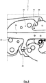
- the movable pliers part 3 On the opposite sides of the leaf spring or spiral spring 36 (and preferably in the free end area of the spring arms 51, 52) the movable pliers part 3 carries drivers 54, 55
- the drivers 54, 55 are designed as driver pins which are held in bores in the movable pliers sub-plates 5a, 5b.
- the driver pin forming the driver 54 is multifunctional, since it is also used to fasten the jaw plate 11 to the pivot bracket 10.
- the drivers 54, 55 In the in the Fig. 4 and 5 In the equilibrium position 48 shown, the drivers 54, 55 are just resting against the leaf spring or spiral spring 36 without generating a significant contact pressure here.
- Fig. 6 and 7th show the crimping pliers 1 in a closed position 53 in which an angle of the hand levers 8, 24 is, for example, in the range from 0 ° to 10 ° (preferably in the range from 0 ° to 5 °).
- the crimping pliers 1 can automatically "spring open” with the elimination of the manual forces.
- the crimping pliers 1 automatically return from the closed position 53 to the equilibrium position 48 as a result of the action of the spring device 35.
- the crimping tool 1 is transferred from the equilibrium position 48 according to FIG Fig. 4 and 5 in a partially open position 56 according to Fig. 8 and 9 or in a (maximum) open position 57 according to Fig. 10 and 11 (whereby, for example, in the partially open position 56 the opening angle of the hand levers 8, 24 can be in the range from 60 ° to 70 °, preferably 65 ° to 68 °, and the opening angle of the hand levers 8, 24 in the open position 57 in the range from 80 ° to 100 °, preferably 85 ° to 95 °), the relative movement of the movable tong part 3 with respect to the fixed tong part 2 causes the driver 54 to move away from the spring arm 52, while the spring arm 52 is still supported on the stop 50.
- the driver 55 increases with the opening movement Force exerted on the spring arm 51.
- the increasing force results in an increasing deformation of the leaf spring or spiral spring 36 and the movement of the spring arm 51 away from the stop 49.
- the increasing loading of the leaf spring or spiral spring 36 has the consequence that the leaf spring or spiral spring 36 exerts a closing force on the tong parts 2, 3 and thus the tong jaws 6, 9.
- the closing force is aimed at restoring the equilibrium position 48.
- the crimping pliers 1 has a locking device 58 as an optional equipment variant.
- the open position 57 can be locked via the locking device 58 in such a way that the open position 57 is maintained despite the closing force of the spring device 35. Only a manual overpressure of the latched open position 57 (which results in a reduction of the latching force or complete elimination of the latching force of the latching device 58) enables the spring device 35 to automatically restore the equilibrium position 48 by means of the closing force provided by the leaf spring or spiral spring 36.
- a locking element 60 (which in particular forms a projection [or a recess]) is pressed against a counter-locking element 61 (which in particular forms a recess [or a projection]) via a locking spring 59, wherein (at least in the surrounding area of the Open position 57) a movement of the hand levers 8, 24 or the pliers jaws 6, 9 relative to one another leads to a relative movement of the latching element 60 and the counter-latching element 61.
- the detent spring 59 of the detent device 58 is formed by a detent spring arm 62 of the leaf spring or spiral spring 36 (here a longitudinal section that extends transversely from the spring arm 52 in the direction of the hand lever 24).
- the detent spring arm 62 In the free end region of the detent spring arm 62 that comes into operative connection with the hand lever 24, the detent spring arm 62 carries a pin 63 which forms the detent element 60.
- the counter-latching element 61 is formed by a recess 64 of a latching contour 65 of the hand lever 24. As it approaches the open position 57, the pin 63 slides with elastic pressure through the detent spring arm 62 along the detent contour 65.
- the pin 63 engages in the recess 64 as a result of the elastic application of the detent spring arm 62.
- the contact pressure of the latching element 60 on the counter-latching element 61 i.e. the bias of the latching spring arm 62
- the geometry of the latching contour 65 in particular the depth of the recess 64 and the inclination of the latching contour 65 in the region of the recess 64
- the closing force of the spring device 35 cannot overcome the locking of the locking device 58. Rather, for this purpose, the user must move the hand lever 24 in the closing direction in such a way that the latching element 60 can be released from the counter-latching element 61 (that is to say the pin 63 can emerge from the recess 64).
- leaf spring or spiral spring 36 is pivotably mounted on the movable pliers part 3 via a pivot pin 66.
- Fig. 12 and 13 show an example of a further embodiment of the spring device 35 encompassed by the invention.
- a coupling arm 67 of the hand lever 24 extends into the region of the movable pliers part 3.
- the free end region of the coupling arm 67 in this case is shown in FIG Fig. 12 and 13
- the equilibrium position 48 shown is caught between two compression springs 68, 69.
- the compression spring 68 forms an opening spring 70
- the compression spring 69 forms a closing spring 71.
- the latching device 58 has a latching element 60 (here a pin 63) carried by the fixed pliers part 2.
- the latching element 60 interacts with a latching contour 65 which is supported by an elastic latching spring arm 62 of the hand lever 24 and which forms the counter-latching element 61, here a recess 64.
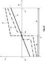
- Fig. 14 shows different characteristics 74, 75, 76 for the spring force 77 of the spring device 35 as a function of the opening angle 78 of the hand levers 8, 24.
- These characteristics 74, 75, 76 represent basic, schematic spring force curves that can be used for any configuration of the spring device 35 and the Pressing or crimping pliers 1 can be brought about.
- the origin of the abscissa corresponds to the closed position 53.
- the equilibrium position 48 is also identified here.
- the specified maximum values of the characteristics 74, 75, 76 correlate with the opening position 57.
- positive values indicate an opening force.
- Negative values on the ordinate represent a closing force of the spring device 35.
- the result is a smooth course of the spring force of the spring device 35 without a jump, a curve-shaped course also being possible depending on the spring characteristics of the spring used.
- Such a characteristic 74 can already be brought about with a single spring whose non-tensioned equilibrium position corresponds to the equilibrium position 48 and which then generates the opening force or the closing force when moving out of the equilibrium position 48 depending on the direction of movement.
- a characteristic according to the characteristic 74 can be brought about if the leaf spring or spiral spring 36 is not pretensioned in the equilibrium position 38. It should be noted, however, that, under certain circumstances, due to the different lever ratios of the drivers 54, 55, the characteristic 74 in the area of the equilibrium position 48 can also have a kink. This can also be used constructively in a targeted manner if different gradients of the characteristic 74 are desired in the partial working strokes.
- a characteristic 74 is used when, in the equilibrium position 48, the opening spring 70 and the closing spring 71 are not pretensioned and the opening spring 70 and the closing spring 71 have the same spring stiffness.
- the characteristic 75 shown in broken lines has a jump in the equilibrium position. This can be desirable if a particularly stable equilibrium position 48 is to be ensured with relatively large restoring forces in the same and / or in the two partial working strokes, the characteristic 75 should have a relatively low gradient at a high level of force.
- Such a characteristic 75 can for the embodiment according to FIG Figs. 1 to 11 be brought about by the leaf spring or spiral spring 36 being pretensioned between the stops 49, 50 in the equilibrium position 48.
- the extent of the bias specifies the level of the jump in the characteristic 75.
- the slope of the characteristic 75 in the two partial working areas is predetermined by the flexural rigidity of the leaf spring or spiral spring 36.
- a characteristic 75 can be brought about in that the opening spring 70 and the closing spring 71 are pretensioned in the equilibrium position 48 without these (as a result of the interaction between the annular shoulders 72, 73 and the stops 49, 50) exerting a force on the drivers 54, 55 produce.
- a characteristic 76 in which the exact equilibrium position 48 is not stable. Rather, the spring device does not generate any spring force in an area around the equilibrium position 48, so that this area is multistable. Only when this surrounding area is left does the illustrated characteristic 76 have a jump with an opening force or closing force that then increases further.
- Such a characteristic 76 can be brought about by, for the exemplary embodiment according to FIG Figs. 1 to 11 in the equilibrium position, the two drivers 54, 55 do not already bear against the leaf spring or spiral spring 36, as shown, but these are still spaced apart are arranged by this. The spacing of the drivers 54, 55 from the leaf spring or spiral spring 36 thus defines the area around the equilibrium position 48 for which no opening force and no closing force is generated. For the characteristic resulting therefrom, leaving the surrounding area (deviating from the characteristic 76 shown) then leads to jumps of the same height with a subsequent, same gradient of the characteristic in the partial working strokes 79, 80.
- a characteristic like the characteristic 76 shown can be brought about by the drivers 54, 55 being arranged in the equilibrium position 48 at a distance from the two compression springs 68, 69 resting on the stops 49, 50.
- the jumps have different heights when the area around the equilibrium position 48 is left. It is then also entirely possible for compression springs 68, 69 to be used with different stiffnesses, so that the characteristic 76 has different gradients in the two partial working strokes.
- a first partial working stroke 79 characterizes the operating positions of the crimping pliers 1 between the open position 57 and the equilibrium position 48
- a second partial working stroke 80 characterizes operating positions of the crimping pliers 1 between the equilibrium position 48 and the closed position 53 indicates.
- the entire stroke between the open position 57 and the closed position 53 is identified as the working stroke 81.
Landscapes
- Engineering & Computer Science (AREA)
- Mechanical Engineering (AREA)
- Manufacturing & Machinery (AREA)
- Manufacturing Of Electrical Connectors (AREA)
- Hand Tools For Fitting Together And Separating, Or Other Hand Tools (AREA)
- Gripping Jigs, Holding Jigs, And Positioning Jigs (AREA)
Description
Die vorliegende Erfindung betrifft eine Press- oder Crimpzange. Mittels der Press- oder Crimpzange kann über eine manuelle Betätigung von Handhebeln ein Verpressen oder Vercrimpen eines Werkstücks erfolgen.The present invention relates to crimping pliers. The pressing or crimping pliers can be used to manually actuate hand levers to press or crimp a workpiece.
Hierbei dient eine Crimpzange insbesondere einer Herstellung einer dauerhaften mechanischen Verbindung und elektrischen Kontaktierung. Dies erfolgt vorzugsweise durch Vercrimpen eines Steckers mit einem Kabel oder einem elektrischen Leiter beliebiger Bauart. Je nach zum Einsatz kommenden Profil der Gesenke können unterschiedliche Crimpvorgänge mit der Crimpzange ausgeführt werden. Beispielsweise kann es sich um einen geschlossenen Crimp handeln, bei dem der Leiter in eine geschlossene Crimpzone eines Steckers oder in eine geschlossene Hülse eingeführt wird und durch plastische Verformung der Crimpzone oder der Hülse vercrimpt wird. Möglich ist aber auch, dass ein offener Crimp erzeugt wird, bei dem der Stecker eine offene Crimpzone aufweist, in die der Leiter von oben eingelegt werden kann. Um lediglich einige, die Erfindung nicht beschränkende Beispiele zu nennen, können mit dem hier einschlägigen Crimpwerkzeug
- Kabelschuhe nach DIN 4623,
- Aluminiumverbinder nach DIN 46329
- Aluminium-Presskabelschuhe nach DIN 48201
- Quetschkabelschuhe nach DIN 46234,
- Stiftkabelschuhe nach DIN 46230 oder
- Verbinder, Stecker oder Kabelschuhe für eine Verbindung mit einem Kabel oder Leiter, wie diese in dem Produktkatalog der WEZAG GmbH Werkzeugfabrik "Werkzeuge für die professionelle Anwendung" mit der Veröffentlichungs-Nr. 10/11 beschrieben sind,
- Cable lugs according to DIN 4623,
- Aluminum connector according to DIN 46329
- Aluminum compression cable lugs according to DIN 48201
- Crimp cable lugs according to DIN 46234,
- Pin cable lugs according to DIN 46230 or
- Connectors, plugs or cable lugs for a connection with a cable or conductor, like those in the product catalog of WEZAG GmbH Werkzeugfabrik "Tools for professional use" with the publication no. 10/11 are described,
vercrimpt werden. Bei dem hergestellten Crimp kann es sich beispielsweise für einen geschlossenen Crimp um einen Sechskant- oder Hexagonalcrimp, einen Vierkantcrimp, einen B-Crimp, einen Trapezcrimp, einen modifizierten Trapezcrimp, einen Ovalcrimp, einen Dorncrimp oder einen Zweidorncrimp handeln. Ein offener Crimp kann bspw. als V-Crimp oder B-Crimp, als Rollcrimp oder als Doppelrollcrimp ausgebildet sein.be crimped. The crimp produced for a closed crimp can be, for example, a hexagonal or hexagonal crimp, a square crimp, a B crimp, a trapezoid crimp, a modified trapezoid crimp, an oval crimp, a mandrel crimp or a two-mandrel crimp. An open crimp can be designed, for example, as a V crimp or B crimp, as a roll crimp or as a double roll crimp.
Zusätzlich zur Herstellung der elektrischen Verbindung zwischen Kabel oder Leiter und Stecker kann eine mechanische Verbindung mittels eines sogenannten Isolationscrimps hergestellt werden. Hierbei kann ein geschlossener Isolationscrimp oder ein offener Isolationscrimp (insbesondere V-Crimp oder B-Crimp, O-Crimp oder OV-Crimp) Einsatz finden. Hinsichtlich weiterer Informationen
- zur Ausgestaltung einer gattungsgemäßen Crimpzange,
- zu möglichen Einsatzbereichen der gattungsgemäßen Crimpzange und/oder
- zu unterschiedlichen möglichen Typen von Crimpverbindungen, welche mittels der gattungsgemäßen Crimpzange hergestellt werden können,
wird auf das Werk - "
Crimptechnik, Herstellung prozesssicherer Verbindungen von elektrischen Leitern und Steckern" der WEZAG GmbH Werkzeugfabrik, Die Bibliothek der Technik 342, Verlag Moderne Industrie, ISBN 978-3-68236-027-7
- to design a generic crimping tool,
- on possible areas of application of the generic crimping tool and / or
- to different possible types of crimp connections that can be made using the generic crimping pliers,
is on the work - "
Crimping technology, production of reliable connections of electrical conductors and plugs "of WEZAG GmbH tool factory, Die Bibliothek der Technik 342, Verlag Moderne Industrie, ISBN 978-3-68236-027-7
Hingegen dient eine gattungsgemäße Presszange vorzugsweise der mechanischen fluiddichten Verbindung in der Fluidtechnik, beispielsweise zur Verbindung von Rohren miteinander oder mit fluidischen Anschlusssteckern. Hierbei erfolgt mittels der Presszange eine plastische Verformung der zu verbindenden Rohre oder eines sogenannten, die mechanische Verbindung und die fluiddichte Abdichtung gewährleistenden Fittings. Beispielhafte Ausführungsformen einer gattungsgemäßen Presszange können den Druckschriften
Bei ansonsten grundsätzlich entsprechender Ausgestaltung einer Crimpzange erfolgt gemäß
Eine weitere Crimpzange ist aus
Der Erfindung liegt die Aufgabe zugrunde, eine manuell betätigte Press- oder Crimpzange vorzuschlagen, welche hinsichtlich der Kraftverhältnisse, des Bedienkomforts und der Bediensicherheit verbessert ist.The invention is based on the object of proposing manually operated crimping or crimping pliers which are improved in terms of force ratios, ease of use and safety.
Die Aufgabe der Erfindung wird erfindungsgemäß mit den Merkmalen des unabhängigen Patentanspruchs gelöst. Weitere bevorzugte erfindungsgemäße Ausgestaltungen sind den abhängigen Patentansprüchen zu entnehmen.The object of the invention is achieved according to the invention with the features of the independent patent claim. Further preferred embodiments according to the invention can be found in the dependent claims.
Der Erfindung liegt die Erkenntnis zugrunde, dass es bei der Gestaltung einer Press- oder Crimpzange zu einem Zielkonflikt kommen kann:
- a) Einerseits kann es wünschenswert sein, dass in der Press- oder Crimpzange zwischen den Zangenbacken eine Feder wirkt. Die Feder beaufschlagt die Zangenbacken in Schließrichtung. In diesem Fall erfolgt eine Öffnung eines Zangenmauls, welches von Gesenken der Press- oder Crimpzange ausgebildet ist, durch Öffnung der Zangenbacken über die antriebsverbundenen Handhebel gegen die Wirkung der Feder. Ist dann ein Werkstück in das Zangenmaul eingelegt, beaufschlagt die Feder beim Loslassen eines Handhebels die Zangenbacken aufeinander zu. Somit ist auch ohne manuelle Applikation einer Kraft auf die Handhebel infolge der Feder das Werkstück zwischen den Gesenken verspannt. Auf diese Weise kann das Werkstück in dem Zangenmaul hinsichtlich seiner Lage und gegenüber einem unbeabsichtigten Herausfallen gesichert sein.
- b) Andererseits hat sich gezeigt, dass es vorteilhaft sein kann, wenn sich die Press- oder Crimpzange nach dem Durchlaufen des Arbeitshubs von selber öffnet. Somit wird in bekannten Press- oder Crimpzangen auch eine Feder eingesetzt, welche die Zangenbacken in Öffnungsrichtung beaufschlagen.
- a) On the one hand, it can be desirable for a spring to act in the pressing or crimping pliers between the pliers jaws. The spring acts on the jaws in the closing direction. In this case, the jaws of the pliers, which are formed by the dies of the pressing or crimping pliers, are opened by opening the pliers jaws via the hand lever connected to the drive against the action of the spring. If a workpiece is then placed in the jaws of the pliers, the spring acts on the jaws of the pliers when a hand lever is released. Thus, even without manual application of a force to the hand lever, the workpiece is between the dies due to the spring tense. In this way, the workpiece can be secured in the pliers jaw with respect to its position and against accidental falling out.
- b) On the other hand, it has been shown that it can be advantageous if the crimping or crimping pliers open by themselves after having completed the working stroke. Thus, a spring is also used in known pressing or crimping pliers, which act on the pliers jaws in the opening direction.
Für aus dem Stand der Technik bekannte Press- oder Crimpzangen ist der Zielkonflikt nicht auflösbar. Somit musste sich - je nach Bewertung der Bedeutung der vorgenannten, sich entgegenstehenden Ziele - der Hersteller der Press- oder Crimpzange für eine in Öffnungsrichtung oder eine in Schließrichtung wirkende Feder entscheiden.For crimping or crimping pliers known from the prior art, the conflict of objectives cannot be resolved. Thus - depending on the assessment of the importance of the aforementioned, conflicting objectives - the manufacturer of the crimping or crimping pliers had to decide between a spring acting in the opening direction or a spring acting in the closing direction.
Erfindungsgemäß wird eine Press- oder Crimpzange vorgeschlagen, die zwei (Gesenke tragende oder ausbildende) Zangenbacken aufweist. Die Zangenbacken sind über einen geeigneten Antriebsmechanismus mit zwei Handhebeln antriebsverbunden. Hierbei ist durch relative Bewegung der Handhebel ein Arbeitshub der Zangenbacken von einer Öffnungsstellung der Zangenbacken in eine Schließstellung der Zangenbacken herbeiführbar. Der Arbeitshub kann dabei einen "Leerhub" aufweisen, in welchem zunächst ein Anlegen der Gesenke an das Werkstück erfolgt, sowie einen Press- oder Crimphub aufweisen, in dem das Werkstück zwischen den Gesenken verpresst oder vercrimpt wird. In der erfindungsgemäßen Press- oder Crimpzange findet mindestens eine Federeinrichtung Einsatz.According to the invention, pressing or crimping pliers are proposed which have two pliers jaws (supporting or forming dies). The pliers jaws are drive-connected via a suitable drive mechanism with two hand levers. Here, a working stroke of the tong jaws from an open position of the tong jaws into a closed position of the tong jaws can be brought about by relative movement of the hand lever. The working stroke can have an "idle stroke" in which the dies are first placed against the workpiece, as well as a press or crimp stroke in which the workpiece is pressed or crimped between the dies. At least one spring device is used in the pressing or crimping pliers according to the invention.
Die mindestens eine Federeinrichtung ist im Rahmen der Erfindung auf besondere Weise ausgebildet und in den Kraftfluss integriert: Die mindestens eine Federeinrichtung gewährleistet zunächst eine Gleichgewichtsstellung. In der Gleichgewichtsstellung übt die Federeinrichtung keine Kraft auf die Zangenbacken aus. Für den Fall eines Einsatzes einer einzigen Federeinrichtung ist damit diese Federeinrichtung in der Gleichgewichtsstellung nicht gespannt (oder nur in einem so geringen Ausmaß gespannt, dass eine in der Press- oder Crimpzange vorhandene Reibung oder ein anderweitiger Widerstand nicht überwunden werden kann). Für den Fall des Einsatzes mehrerer Federeinrichtungen können diese sämtlich nicht gespannt sein oder die Wirkung der gespannten Federeinrichtungen hebt sich gegenseitig auf. Die genannte Gleichgewichtsstellung der Zangenbacken ist dabei zwischen der Öffnungsstellung und der Schließstellung der Zangenbacken angeordnet (beispielsweise zwischen 20 % bis 80 % oder 30 % bis 60 % des Arbeitshubes).The at least one spring device is designed in a special way within the scope of the invention and is integrated into the force flow: the at least one spring device initially ensures an equilibrium position. In the equilibrium position, the spring device does not exert any force on the jaws. In the event that a single spring device is used, this spring device is not tensioned in the equilibrium position (or is only tensioned to such a small extent that friction or any other resistance in the crimping pliers cannot be overcome). In the event that several spring devices are used, none of them can be tensioned or the action of the tensioned spring devices cancels one another. The said equilibrium position the pincer jaw is arranged between the open position and the closed position of the pincer jaws (for example between 20% to 80% or 30% to 60% of the working stroke).
Die Gleichgewichtsstellung unterteilt den Arbeitshub in einen ersten Teilarbeitshub, der zwischen der Öffnungsstellung und der Gleichgewichtsstellung der Zangenbacken angeordnet ist, sowie einen zweiten Teilarbeitshub, der zwischen der Gleichgewichtsstellung und der Schließstellung angeordnet ist. In dem ersten Teilarbeitshub übt die mindestens eine Federeinrichtung eine Schließkraft auf die Zangenbacken aus. Hingegen übt die Federeinrichtung in dem zweiten Teilarbeitshub eine Öffnungskraft auf die Zangenbacken aus.The equilibrium position divides the working stroke into a first partial working stroke, which is arranged between the open position and the equilibrium position of the gripper jaws, and a second partial working stroke, which is arranged between the equilibrium position and the closed position. In the first partial working stroke, the at least one spring device exerts a closing force on the gripper jaws. In contrast, the spring device exerts an opening force on the jaws in the second partial working stroke.
Diese erfindungsgemäße Ausgestaltung ermöglicht insbesondere die folgende vorteilhafte Benutzung der Press- oder Crimpzange:
- Zu Beginn eines Press- oder Crimpvorgangs befindet sich die Press- oder Crimpzange in der Gleichgewichtsstellung. Die Gleichgewichtsstellung ist stabil, da die Federeinrichtung bei kleinen Auslenkungen in Öffnungsrichtung eine Schließkraft und bei kleinen Auslenkungen in Schließrichtung eine Öffnungskraft herbeiführt. Auf diese Weise kann automatisch eine Rückführung in die Gleichgewichtsstellung erfolgen.
- Soll ein Werkstück in ein (von Gesenken der Press- oder Crimpzange ausgebildetes) Zangenmaul eingelegt werden, kann der Benutzer durch Aufbringung einer Öffnungskraft auf die Handhebel eine Öffnung der Zangenbacken in Richtung der Öffnungsstellung herbeiführen.
- Ist das Werkstück in das Zangenmaul eingelegt und sind die Abmessungen des Werkstücks gegenüber der Größe des Zangenmauls derart, dass ohne ein Verpressen oder Vercrimpen des Werkstücks eine Schließung der Zangenbacken mit den Gesenken zurück bis in die Gleichgewichtsstellung nicht möglich ist, werden die Zangenbacken mit den Gesenken durch die Federeinrichtung mit der Schließkraft gegen das Werkstück gepresst. Dadurch wird eine Sicherung der Position und/oder Lage des Werkstücks in dem Zangenmaul (und auch ein Herausfallen des Werkstücks aus dem Zangenmaul) gewährleistet, auch wenn der Benutzer keine Schließkraft auf die Handhebel aufbringt.
- Wird dann der Press- oder Crimphub ausgeführt, indem der Benutzer durch Aufbringung einer Schließkraft auf die Handhebel die Schließstellung der Zangenbacken herbeiführt, kann nach Beendigung des Press- oder Crimphubs die Federeinrichtung in dem zweiten Teilarbeitshub eine Öffnungskraft auf die Zangenbacken ausüben. Hierdurch "springt" das Zangenmaul nach Beseitigung der auf die Handhebel applizierten Schließkräfte durch den Benutzer automatisch auf.
- At the beginning of a pressing or crimping process, the pressing or crimping pliers are in the equilibrium position. The equilibrium position is stable because the spring device brings about a closing force with small deflections in the opening direction and an opening force with small deflections in the closing direction. In this way, a return to the equilibrium position can take place automatically.
- If a workpiece is to be inserted into a pliers jaw (formed by dies of the crimping or crimping pliers), the user can bring about an opening of the pliers jaws in the direction of the opening position by applying an opening force to the hand lever.
- If the workpiece is inserted into the jaws and the dimensions of the workpiece compared to the size of the jaws are such that it is not possible to close the jaws with the dies back to the equilibrium position without pressing or crimping the workpiece, the jaws with the dies pressed against the workpiece by the spring device with the closing force. This ensures that the position and / or location of the workpiece in the pliers jaws (and also that the workpiece falls out of the pliers jaws) is ensured, even if the user does not apply any closing force to the hand lever.
- If the press or crimp stroke is then carried out in that the user brings about the closed position of the pliers jaws by applying a closing force to the hand lever, the spring device in the second can, after completion of the press or crimp stroke Partial working stroke exert an opening force on the gripper jaws. As a result, the pliers jaws "open" automatically after the user has eliminated the closing forces applied to the hand lever.
Vorzugsweise erzeugt die Federeinrichtung eine nichtlineare Charakteristik der Federkraft. Die nichtlineare Charakteristik der Federkraft weist insbesondere in der Gleichgewichtsstellung oder zwischen den beiden Teilarbeitshüben einen Knick und/oder einen Sprung auf.The spring device preferably generates a non-linear characteristic of the spring force. The non-linear characteristic of the spring force exhibits a kink and / or a jump, particularly in the equilibrium position or between the two partial working strokes.
Die Federeinrichtung kann eine oder mehrere Federn aufweisen. Hierbei kann die mindestens eine Feder aus einem beliebigen Material (beispielsweise Metall, Kunststoff, ein Elastomermaterial) und auch aus einem Verbundmaterial hergestellt sein. Es kann sich um eine Druckfeder, Zugfeder, eine Drehwinkelfeder, eine Torsionsfeder oder eine Feder beliebiger sonstiger Bauart handeln. Für den Fall des Einsatzes mehrerer Federn können diese in mechanischer Reihenschaltung oder Parallelschaltung angeordnet sein und/oder an unterschiedlichen Stellen in den Kraftfluss integriert sein. Möglich ist auch, dass eine Feder in Öffnungsrichtung wirkt und eine andere Feder in Schließrichtung wirkt. Vorzugsweise erzeugt die Federeinrichtung eine nichtlineare Charakteristik, die insbesondere in der Gleichgewichtsstellung oder zwischen den beiden Teilarbeitshüben einen Knick und/oder einen Sprung aufweist.The spring device can have one or more springs. Here, the at least one spring can be made from any material (for example metal, plastic, an elastomer material) and also from a composite material. It can be a compression spring, tension spring, an angle spring, a torsion spring or a spring of any other type. If several springs are used, they can be arranged in mechanical series connection or parallel connection and / or integrated into the force flow at different points. It is also possible that one spring acts in the opening direction and another spring acts in the closing direction. The spring device preferably generates a non-linear characteristic which, in particular, has a kink and / or a jump in the equilibrium position or between the two partial working strokes.
Für eine Ausgestaltung der Erfindung weist die Federeinrichtung eine Schließfeder und eine Öffnungsfeder auf. In diesem Fall erzeugt in dem ersten Teilarbeitshub die Schließfeder die Schließkraft, während in dem zweiten Teilarbeitshub die Öffnungsfeder die Öffnungskraft erzeugt. Möglich ist hierbei, dass in dem ersten Teilarbeitshub die Öffnungsfeder von der Antriebsverbindung entkoppelt ist, während in dem zweiten Teilarbeitshub die Schließfeder von der Antriebsverbindung entkoppelt sein kann.For one embodiment of the invention, the spring device has a closing spring and an opening spring. In this case, the closing spring generates the closing force in the first partial working stroke, while the opening spring generates the opening force in the second partial working stroke. It is possible here that the opening spring is decoupled from the drive connection in the first partial working stroke, while the closing spring can be decoupled from the drive connection in the second partial working stroke.
Für eine andere Variante der Erfindung weist die Federeinrichtung (vorzugsweise ausschließlich) eine Feder auf. Diese Feder ist dann multifunktional eingesetzt, indem diese sowohl in dem ersten Teilarbeitshub die Schließkraft erzeugt als auch in dem zweiten Teilarbeitshub die Öffnungskraft erzeugt.For another variant of the invention, the spring device (preferably exclusively) has a spring. This spring is then used multifunctionally in that it generates the closing force in the first partial working stroke as well as generating the opening force in the second partial working stroke.
Im Rahmen der Erfindung ist durchaus möglich, dass eine Feder der Federeinrichtung über den gesamten Arbeitshub mit der Bewegung der Zangenbacken gekoppelt ist. In diesem Fall verändert sich auch über den gesamten Arbeitshub die Beaufschlagung der Feder. Für einen besonderen Vorschlag der Erfindung weist die Press- oder Crimpzange mindestens einen Anschlag auf. Der Anschlag gibt eine extremale Auslenkung eines Federfußpunkts der Federeinrichtung vor, wobei es sich vorzugsweise um eine minimale Auslenkung handelt. Des Weiteren ist für diese Ausgestaltung der Press- oder Crimpzange ein Mitnehmer vorhanden. Der Mitnehmer nimmt in dem Teilarbeitshub den Federfußpunkt der Federeinrichtung mit und bewegt diesen von dem Anschlag weg, womit sich dann die Beaufschlagung der Feder verändert. Vorzugsweise bleibt in dem anderen Teilarbeitshub der Federfußpunkt der Federeinrichtung an dem Anschlag. Somit verändert sich für den anderen Teilarbeitshub die Beaufschlagung der Feder nicht.Within the scope of the invention, it is entirely possible for a spring of the spring device to be coupled to the movement of the tong jaws over the entire working stroke. In this case changed the loading of the spring over the entire working stroke. For a particular proposal of the invention, the pressing or crimping pliers have at least one stop. The stop specifies an extreme deflection of a spring base point of the spring device, which is preferably a minimal deflection. Furthermore, a driver is available for this embodiment of the pressing or crimping pliers. In the partial working stroke, the driver takes the spring base point of the spring device with it and moves it away from the stop, which then changes the action on the spring. The spring base of the spring device preferably remains at the stop in the other partial working stroke. Thus, the application of the spring does not change for the other partial working stroke.
Handelt es sich bei der Feder um eine Druckfeder, gibt der Anschlag eine minimale Druckbeaufschlagung der Druckfeder vor. In dem Teilarbeitshub, in welchem der Mitnehmer den Federfußpunkt der Druckfeder mitnimmt und von dem Anschlag wegbewegt, erhöht sich die Druckkraft in der Druckfeder. Die sich erhöhende Druckkraft der Druckfeder kann dann zur Erzeugung der Schließkraft oder der Öffnungskraft verwendet werden. Das Entsprechende gilt für den Einsatz einer Zugfeder - hier gibt der Anschlag eine minimale Zugkraft in der Zugfeder vor, während mit der weiteren Beaufschlagung der Zugfeder durch den Mitnehmer die Auslenkung und die Zugkraft größer werden.If the spring is a compression spring, the stop specifies a minimal application of pressure to the compression spring. In the partial working stroke in which the driver takes the spring base of the compression spring with it and moves it away from the stop, the compressive force in the compression spring increases. The increasing compressive force of the compression spring can then be used to generate the closing force or the opening force. The same applies to the use of a tension spring - here the stop provides a minimum tensile force in the tension spring, while the deflection and the tensile force increase as the driver continues to act on the tension spring.
Für einen besonderen Vorschlag der Erfindung sind zwei Anschläge und zugeordnete Mitnehmer vorhanden. An den beiden Anschlägen kann in der Gleichgewichtsstellung eine einzige Feder gefangen sein. In diesem Fall wird während des ersten Teilarbeitshubs über einen Mitnehmer ein Federfußpunkt der Feder mitgenommen. In dem anderen Teilarbeitshub wird der andere Federfußpunkt von dem anderen Mitnehmer mitgenommen. Sind hingegen zwei Federn eingesetzt, kann in der Gleichgewichtsstellung jede Feder jeweils an einem zugeordneten Anschlag abgestützt sein. Während eines Teilarbeitshubs bewegt in diesem Fall ein Mitnehmer den Federfußpunkt einer Feder von dem zugeordneten Anschlag weg, während der andere Federfußpunkt weiterhin an dem zugeordneten Anschlag verbleibt. In dem anderen Teilarbeitshub bewegt dann der andere Mitnehmer den Federfußpunkt der anderen Feder von dem zugeordneten Anschlag weg, während in diesem Fall der Federfußpunkt der erstgenannten Feder weiterhin an dem Anschlag abgestützt bleibt.For a particular proposal of the invention, there are two stops and associated drivers. A single spring can be caught on the two stops in the equilibrium position. In this case, a spring base point of the spring is carried along by a driver during the first partial working stroke. In the other partial working stroke, the other spring base point is taken along by the other driver. If, on the other hand, two springs are used, each spring can be supported on an associated stop in the equilibrium position. In this case, during a partial working stroke, a driver moves the spring base point of a spring away from the assigned stop, while the other spring base point remains at the assigned stop. In the other partial working stroke, the other driver then moves the spring base of the other spring away from the associated stop, while in this case the spring base of the first-mentioned spring continues to be supported on the stop.
Der mindestens eine Anschlag und der mindestens eine Mitnehmer können an beliebigen Bauelementen der Press- oder Crimpzange angeordnet sein, solange während des Arbeitshubs eine Relativbewegung der Bauelemente, an welchen der Anschlag und der Mitnehmer angeordnet sind, erfolgt. So ist beispielsweise möglich, dass der Mitnehmer an einem Handhebel abgestützt ist, während der zugeordnete Anschlag an einer (vorzugsweise bewegten) Zangenbacke befestigt ist. Für eine erfindungsgemäße Ausgestaltung der Press- oder Crimpzange ist aber der Anschlag an einem Zangenkopf befestigt oder von diesem getragen, während der Mitnehmer an einer gegenüber dem Zangenkopf über den Arbeitshub bewegten Zangenbacke befestigt oder von dieser getragen ist. Sofern zwei Anschläge und Mitnehmer vorhanden sind, kann dies auch für beide Anschläge und Mitnehmer gelten.The at least one stop and the at least one driver can be arranged on any components of the crimping or crimping pliers, as long as one during the working stroke Relative movement of the components on which the stop and the driver are arranged takes place. For example, it is possible for the driver to be supported on a hand lever, while the assigned stop is attached to a (preferably moved) pliers jaw. For an embodiment of the crimping or crimping pliers according to the invention, however, the stop is attached to a pliers head or carried by this, while the driver is attached to or carried by a pliers jaw moved over the working stroke with respect to the pliers head. If there are two stops and drivers, this can also apply to both stops and drivers.
Grundsätzlich kann die mindestens eine Feder der Federeinrichtung beliebig ausgestaltet sein. Für eine besondere Ausgestaltung der Federeinrichtung findet eine einzige Feder Einsatz, die als U-förmige Biegefeder oder Blattfeder ausgebildet ist. Eine derartige Biegefeder oder Blattfeder stellt eine konstruktiv einfache Feder mit hoher Lebensdauer dar, bei welcher über die Querschnitte der Biegefeder oder Blattfeder und ggf. den Querschnittsverlauf, den Verlauf der Längsachse der Biegefeder oder Blattfeder, das eingesetzte Material und die wirksame Länge der Biegefeder oder Blattfeder konstruktiv die Steifigkeit und eine etwaige Nichtlinearität des Steifigkeitsverhaltens vorgegeben werden kann. Indem die Biegefeder oder Blattfeder U-förmig ausgebildet ist, können die unterschiedlichen Federarme des U für die Gestaltung der Steifigkeit verwendet werden.In principle, the at least one spring of the spring device can be designed as desired. For a special embodiment of the spring device, a single spring is used, which is designed as a U-shaped spiral spring or leaf spring. Such a spiral spring or leaf spring represents a structurally simple spring with a long service life, in which the cross sections of the spiral spring or leaf spring and possibly the cross-sectional profile, the course of the longitudinal axis of the spiral spring or leaf spring, the material used and the effective length of the spiral spring or leaf spring the stiffness and any non-linearity of the stiffness behavior can be specified constructively. Because the spiral spring or leaf spring is U-shaped, the different spring arms of the U can be used to configure the rigidity.
Eine besonders gute Integration der U-förmigen Biegefeder oder Blattfeder in die Press- oder Crimpzange kann sich für eine Ausgestaltung der Erfindung ergeben, wenn sich die Federarme der U-förmigen Biegefeder oder Blattfeder in Richtung einer Längsachse des Zangenkopfs oder in Richtung der geschlossenen Handhebel erstrecken.A particularly good integration of the U-shaped spiral spring or leaf spring into the pressing or crimping pliers can result for an embodiment of the invention if the spring arms of the U-shaped spiral spring or leaf spring extend in the direction of a longitudinal axis of the pliers head or in the direction of the closed hand lever .
Für einen weiteren Vorschlag ist die Press- oder Crimpzange mit einem Zwangsgesperre ausgestattet. Ein derartiges Zwangsgesperre sichert eine einmal erreichte Teilschließstellung der Zangenbacken gegen eine Öffnung. Dadurch wird auch bei einer temporären Beseitigung der auf die Handhebel wirkenden Handkräfte eine erreichte Teilschließstellung aufrechterhalten. Ein derartiges Zwangsgesperre ermöglicht eine Öffnung der Zangenbacken erst dann, wenn der Arbeitshub vollständig durchlaufen ist. Mit diesen Maßnahmen kann die Prozesssicherheit erhöht werden kann. Infolge der erfindungsgemäßen Ausgestaltung bewegt mit dem vollständigen Durchlaufen des Arbeitshubs (also mit der Entriegelung des Zwangsgesperres) die Federeinrichtung die Zangenbacken automatisch zurück in die Gleichgewichtsstellung. Vorzugsweise ist im Rahmen der Erfindung das Zwangsgesperre derart ausgelegt, dass dieses ausschließlich in dem zweiten Teilarbeitshub (oder auch nur in einem endseitigen Teilabschnitt desselben) wirksam wird, so dass dieses in dem ersten Teilarbeitshub die angestrebte Wirkung der Federeinrichtung nicht behindert.For a further suggestion, the crimping or crimping tool is equipped with an automatic lock. Such a compulsory lock secures a partial closed position of the jaws against an opening that has been reached. As a result, a partial closed position is maintained even if the manual forces acting on the hand lever are temporarily eliminated. Such a compulsory lock enables the jaws to be opened only when the working stroke has been completed. With these measures, the process reliability can be increased. As a result of the embodiment according to the invention, the spring device automatically moves the gripper jaws back into the equilibrium position when the working stroke is fully completed (that is, when the automatic locking mechanism is unlocked). Preferably is in the frame According to the invention, the automatic locking mechanism is designed in such a way that it is only effective in the second partial working stroke (or only in an end partial section of the same), so that this does not hinder the desired effect of the spring device in the first partial working stroke.
Durchaus möglich ist im Rahmen der Erfindung, dass die Öffnungsstellung (in welcher ein Einlegen des Werkstücks in das Zangenmaul erfolgen kann) angesichts der Wirkung der Federeinrichtung nur aufrechterhalten wird, wenn der Benutzer Öffnungskräfte auf die Handhebel oder die Zangenbacken aufbringt, die der Beaufschlagung der Zangenbacken durch die Federeinrichtung entgegenwirken. Für einen weiteren Vorschlag der Erfindung kann die Notwendigkeit, die Press- oder Crimpzange manuell in der Öffnungsstellung zu halten, vermieden werden: Für diesen Vorschlag ist eine Rastiereinrichtung oder eine Verriegelungseinrichtung vorhanden. Die Rastiereinrichtung oder Verriegelungseinrichtung sichert die Öffnungsstellung, so dass trotz der in der Öffnungsstellung wirkenden Schließkraft der Federeinrichtung die Öffnungsstellung automatisch beibehalten werden kann.It is entirely possible within the scope of the invention that the open position (in which the workpiece can be inserted into the jaws of the pliers) is only maintained in view of the action of the spring device if the user applies opening forces to the hand lever or the pliers jaws, which the force of the action of the pliers jaws counteract by the spring device. For a further suggestion of the invention, the need to manually hold the crimping or crimping pliers in the open position can be avoided: a latching device or a locking device is available for this suggestion. The latching device or locking device secures the open position so that the open position can be automatically maintained despite the closing force of the spring device acting in the open position.
Hierbei wird unter einer Rastiereinrichtung insbesondere eine Einrichtung verstanden, welche eine Rastierung bewirkt, die zu einer Rastkraft führt, die größer ist als die von der Federeinrichtung erzeugte Schließkraft. Durch Aufbringung manueller Schließkräfte (beispielsweise über die Handhebel oder durch unmittelbar auf die Zangenbacken aufgebrachte Schließkräfte) kann ein Überdrücken der Rastierung erfolgen, so dass die Öffnungsstellung verlassen wird. Ist die Rastierung derart überdrückt, entfällt die Rastierkraft zumindest teilweise. Infolge dieses Entfalls überwiegt die von der Federeinrichtung erzeugte Schließkraft. Eine Rückführung in die Gleichgewichtsstellung (oder ein Anlegen der Gesenke an das Werkstück infolge der Federeinrichtung) ist somit möglich.In this context, a locking device is understood to mean, in particular, a device that effects a locking that leads to a locking force that is greater than the closing force generated by the spring device. By applying manual closing forces (for example by means of the hand lever or by closing forces applied directly to the pliers jaws) the detent can be overpressed so that the open position is left. If the latching is overridden in this way, the latching force is at least partially eliminated. As a result of this omission, the closing force generated by the spring device predominates. A return to the equilibrium position (or a placement of the dies on the workpiece as a result of the spring device) is thus possible.
Hingegen wird unter einer Verriegelungseinrichtung insbesondere eine Einrichtung verstanden, in welcher eine Öffnungsstellung derart verriegelt wird, dass diese nicht einfach durch Aufbringung von Schließkräften (beispielsweise über die Handhebel oder durch unmittelbar auf die Zangenbacken aufgebrachte Schließkräfte) verlassen werden kann. Vielmehr ist eine manuelle Betätigung eines Verriegelungselements erforderlich, welche dann die Verriegelung löst, so dass dann die Federeinrichtung eine Rückführung der Zangenbacken in die Gleichgewichtsstellung herbeiführen kann oder ein Anlegen der Gesenke an das Werkstück herbeiführen kann.In contrast, a locking device is understood to mean in particular a device in which an open position is locked in such a way that it cannot be left simply by applying closing forces (for example via the hand lever or by closing forces applied directly to the pliers jaws). Rather, manual actuation of a locking element is required, which then releases the locking so that the spring device can then bring the pliers jaws back into the equilibrium position or bring the dies to the workpiece.
Durchaus möglich ist, dass in der Rastiereinrichtung oder Verriegelungseinrichtung eine separat ausgebildete Rastier- oder Verriegelungsfeder Einsatz findet. Für eine Ausgestaltung der erfindungsgemäßen Press- oder Crimpzange ist die oder eine Feder der Federeinrichtung multifunktional, indem diese Feder einerseits die Öffnungskraft und/oder die Schließkraft erzeugt. Darüber hinaus erzeugt diese Feder auch eine Rastierkraft der Rastiereinrichtung oder eine Verriegelungskraft der Verriegelungseinrichtung.It is entirely possible for a separately designed latching or locking spring to be used in the latching device or locking device. For an embodiment of the pressing or crimping pliers according to the invention, the spring or a spring of the spring device is multifunctional in that this spring generates the opening force and / or the closing force on the one hand. In addition, this spring also generates a locking force of the locking device or a locking force of the locking device.
Für die konstruktive Ausgestaltung einer derartigen multifunktionalen Feder gibt es vielfältige Möglichkeiten. Für einen Vorschlag der Erfindung trägt ein Federarm der U-förmigen Blattfeder oder Biegefeder einen Rastfederarm der Rastiereinrichtung. Der Rastfederarm bildet in diesem Fall federnd ein Rastelement aus oder trägt dieses. Das Rastelement tritt rastierend in Wechselwirkung mit einem Gegen-Rastelement, wobei über den Arbeitshub und insbesondere im Umgebungsbereich der Öffnungsstellung eine Relativbewegung des Gegen-Rastelements relativ zu dem Rastelement erfolgt.There are many possibilities for the structural design of such a multifunctional spring. For a proposal of the invention, a spring arm of the U-shaped leaf spring or spiral spring carries a latching spring arm of the latching device. In this case, the detent spring arm resiliently forms a detent element or carries it. The latching element interacts with a latching counter-latching element, with a relative movement of the counter-latching element relative to the latching element taking place over the working stroke and in particular in the area surrounding the open position.
Eine weitere Ausgestaltung der erfindungsgemäßen Press- oder Crimpzange hat einen besonderen konstruktiven Aufbau der Press- oder Crimpzange und eine besondere Antriebskinetik zum Gegenstand: Für diese Ausführungsform bildet ein festes Zangenteil (welches ein- oder mehrstückig ausgebildet sein kann) eine feste Zangenbacke und einen festen Handhebel aus. Ein bewegliches Zangenteil (welches ebenfalls ein- oder mehrstückig ausgebildet sein kann) bildet dann eine bewegliche Zangenbacke aus. Das bewegliche Zangenteil ist über ein Schwenklager an dem festen Zangenteil verschwenkbar angelenkt. An dem festen Zangenteil ist auch über ein Schwenklager ein beweglicher Handhebel verschwenkbar angelenkt. Der bewegliche Handhebel ist dann über eine Antriebsverbindung (insbesondere einen Druckhebel- oder einen Kniehebeltrieb) mit dem beweglichen Zangenteil verbunden.Another embodiment of the pressing or crimping pliers according to the invention has a special construction of the pressing or crimping pliers and a special drive kinetics: For this embodiment, a fixed pliers part (which can be made in one or more pieces) forms a fixed pliers jaw and a fixed hand lever out. A movable pliers part (which can also be designed in one or more pieces) then forms a movable pliers jaw. The movable tong part is pivotably articulated to the fixed tong part via a pivot bearing. A movable hand lever is pivotably articulated to the fixed pliers part via a pivot bearing. The movable hand lever is then connected to the movable pliers part via a drive connection (in particular a pressure lever drive or a toggle lever drive).
Für einen Vorschlag der Erfindung bildet in diesem Fall der bewegliche Handhebel das Gegen-Rastelement aus.For a proposal of the invention, the movable hand lever forms the counter-locking element in this case.
Für eine konstruktive Ausgestaltung der Press- oder Crimpzange ist in diesem Fall das Schwenklager, über welches das bewegliche Zangenteil verschwenkbar an dem festen Zangenteil angelenkt ist, in der dem Zangenkopf abgewandten Hälfte der Längserstreckung des festen Zangenteils angeordnet (wobei sich das Schwenklager in diesem Fall bspw. in einem Abstand von dem vorderen Endbereich des Langenkopfes befinden kann, der mehr als 55 %, mehr als 60 %, mehr als 65 %, mehr als 70 % oder sogar mehr als 75 % der Längserstreckung des festen Zangenteils beträgt). Durch die Verlagerung des Schwenklagers von dem Zangenkopf weg kann auch der Schwenkradius der Gesenke vergrößert werden. Für einen vorgegebenen Hub der Gesenke kann auf diese Weise der Schwenkwinkel der Gesenke über den Arbeitshub verringert werden. Eine zu große Verschwenkung der Gesenke relativ zueinander hat sich als negativ für das Press- oder Crimpergebnis herausgestellt.For a structural design of the crimping or crimping pliers, the pivot bearing, via which the movable pliers part is pivotably articulated to the fixed pliers part, is arranged in the half of the longitudinal extension of the fixed pliers part facing away from the pliers head (the pivot bearing in this case, for example Can be located at a distance from the front end region of the long head which is more than 55%, more than 60%, more than 65%, more than 70% or even more than 75% of the length of the fixed pliers part). By moving the pivot bearing away from the pliers head, the pivot radius of the dies can also be increased. For a given stroke of the dies, the swivel angle of the dies can be reduced over the working stroke in this way. Too much pivoting of the dies relative to one another has proven to be negative for the pressing or crimping result.
Vorteilhafte Weiterbildungen der Erfindung ergeben sich aus den Patentansprüchen, der Beschreibung und den Zeichnungen. Die in der Beschreibung genannten Vorteile von Merkmalen und von Kombinationen mehrerer Merkmale sind lediglich beispielhaft und können alternativ oder kumulativ zur Wirkung kommen, ohne dass die Vorteile zwingend von erfindungsgemäßen Ausführungsformen erzielt werden müssen. Die Erfindung ist durch den unabhängigen Anspruch 1 vorgegeben, bevorzugte Ausführungsformen sind durch die abhängigen Ansprüche definiert.Advantageous further developments of the invention emerge from the patent claims, the description and the drawings. The advantages of features and of combinations of several features mentioned in the description are only exemplary and can come into effect alternatively or cumulatively without the advantages necessarily having to be achieved by embodiments according to the invention. The invention is specified by
Die in den Patentansprüchen und der Beschreibung genannten Merkmale sind bezüglich ihrer Anzahl so zu verstehen, dass genau diese Anzahl oder eine größere Anzahl als die genannte Anzahl vorhanden ist, ohne dass es einer expliziten Verwendung des Adverbs "mindestens" bedarf. Wenn also beispielsweise von einer Feder die Rede ist, ist dies so zu verstehen, dass genau eine Feder, zwei Federn oder mehr Federn vorhanden sind. Diese Merkmale können durch andere Merkmale ergänzt werden oder die einzigen Merkmale sein, aus denen das jeweilige Erzeugnis besteht.The number of features mentioned in the claims and the description are to be understood in such a way that precisely this number or a greater number than the stated number is present without the need for the explicit use of the adverb "at least". So if, for example, a spring is mentioned, it is to be understood that there is exactly one spring, two springs or more springs. These characteristics can be supplemented by other characteristics or be the only characteristics that make up the product in question.
Die in den Patentansprüchen enthaltenen Bezugszeichen stellen keine Beschränkung des Umfangs der durch die Patentansprüche geschützten Gegenstände dar. Sie dienen lediglich dem Zweck, die Patentansprüche leichter verständlich zu machen.The reference signs contained in the claims do not represent a restriction of the scope of the subject matter protected by the claims. They only serve the purpose of making the claims easier to understand.
Im Folgenden wird die Erfindung anhand in den Figuren dargestellter bevorzugter Ausführungsbeispiele weiter erläutert und beschrieben.
- Fig. 1
- zeigt eine Crimpzange in einer räumlichen Explosionsdarstellung.
- Fig. 2
- zeigt die Crimpzange gemäß
Fig. 1 in einer räumlichen Darstellung. - Fig. 3
- zeigt in einer Seitenansicht Bauelemente der Crimpzange gemäß
Fig. 1 und2 zur Verdeutlichung der Antriebskinetik. - Fig. 4, 6, 8, 10
- zeigen die Crimpzange gemäß
Fig. 1-3 in Seitenansichten in unterschiedlichen Betriebsstellungen. - Fig. 5, 7, 9, 11
- zeigen Details V, VII, IX, XI der Crimpzangen gemäß
Fig. 4 ,6 ,8 ,10 . - Fig. 12
- zeigt eine alternative Ausführungsform einer Crimpzange in einer Seitenansicht.
- Fig. 13
- zeigt ein Detail XIII der Crimpzange gemäß
Fig. 12 . - Fig. 14
- zeigt unterschiedliche Federcharakteristiken einer Federeinrichtung einer Press- oder Crimpzange.
- Fig. 1
- shows a crimping tool in a three-dimensional exploded view.
- Fig. 2
- shows the crimping tool according to
Fig. 1 in a spatial representation. - Fig. 3
- shows in a side view components of the crimping tool according to FIG
Fig. 1 and2 to clarify the drive kinetics. - Figures 4, 6, 8, 10
- show the crimping tool according to
Fig. 1-3 in side views in different operating positions. - Figures 5, 7, 9, 11
- show details V, VII, IX, XI of the crimping pliers according to FIG
Fig. 4 ,6 ,8th ,10 . - Fig. 12
- shows an alternative embodiment of a crimping tool in a side view.
- Fig. 13
- shows a detail XIII of the crimping tool according to FIG
Fig. 12 . - Fig. 14
- shows different spring characteristics of a spring device of a crimping tool.
Zangenteilplatten 4a, 4b auf. Das bewegliche Zangenteil 3 weist zwei bewegliche Zangenteilplatten 5a, 5b auf. Das feste Zangenteil 2 weist eine feste Zangenbacke 6, einen Verbindungsbereich 7 und einen festen Handhebel 8 auf. Für das dargestellte Ausführungsbeispiel bildet die feste Zangenteilplatte 4a die feste Zangenbacke 6, den Verbindungsbereich 7 und den festen Handhebel 8 aus. Hingegen bildet die feste Zangenteilplatte 4b lediglich die feste Zangenbacke 6 und den Verbindungsbereich 7 aus. Das bewegliche Zangenteil 3 verfügt über eine bewegliche Zangenbacke 9. Die bewegliche Zangenbacke 9 ist an einem Schwenkträger 10 gehalten. Hierbei sind die beweglichen Zangenteilplatten 5a, 5b zweiteilig ausgebildet mit Zangenbackenplatten 11a, 11b und Schwenkträgerplatten 12a, 12b.
Das bewegliche Zangenteil 3 ist über ein Schwenklager 13 verschwenkbar um eine Schwenkachse 14 an dem festen Zangenteil 2 gelagert. Dies erfolgt für das dargestellte Ausführungsbeispiel durch einen Schwenkbolzen 15. Der Schwenkbolzen 15 erstreckt sich durch eine Verschwenkung ermöglichende Durchgangsbohrungen 16a, 16b, 16c, 16d der beweglichen Zangenteilplatten 5a, 5b und festen Zangenteilplatten 4a, 4b. Hierbei sind die beiden beweglichen Zangenteilplatten 5a, 5b zwischen den festen Zangenteilplatten 4a, 4b aufgenommen. Die Zangenbackenplatten 11a, 11b sind so an die Schwenkträgerplatten 12a, 12b angesetzt und an diesen gehalten, dass sich die Zangenbackenplatten 11a, 11b in den durch die festen Zangenteilplatten 4a, 4b vorgegebenen parallelen Ebenen erstrecken und sich während der Verschwenkung in diesen Ebenen bewegen.The
Ungefähr mittig von der Schwenkträgerplatte 12 ist an das bewegliche Zangenteil 3 über ein Schwenklager 17 ein Endbereich eines Druckhebels 18 (der hier mit zwei Druckhebelplatten 19a, 19b gebildet ist) angelenkt. Für das dargestellte Ausführungsbeispiel ist das Schwenklager 17 mit einem Schwenkbolzen 20 gebildet. Der Schwenkbolzen 20 findet Aufnahme in Durchgangsbohrungen 21a, 21b, 21c, 21d der Druckhebelplatte 19b, der Schwenkträgerplatte 12b, der Schwenkträgerplatte 12a und der Druckhebelplatte 19a. Auf diese Weise ist eine Schwenkachse 22 des Schwenklagers 17 vorgegeben. Für das dargestellte Ausführungsbeispiel sind die beiden Druckhebelplatten 19 nicht zwischen den festen Zangenteilplatten 4a, 4b, sondern außerhalb derselben angeordnet. Aus diesem Grund erstreckt sich der Schwenkbolzen 20 durch Langlöcher 23a, 23b der festen Zangenteilplatten 4a, 4b. Die Langlöcher 23a, 23b sind so geformt und angeordnet, dass die festen Zangenteilplatten 4a, 4b die Bewegung des Schwenkbolzens 20 mit der Verschwenkung des beweglichen Zangenteils 3 nicht behindern.Approximately in the center of the pivot support plate 12, an end region of a pressure lever 18 (which is formed here with two
Ein beweglicher Handhebel 24 (der hier zwei bewegliche Handhebelplatten 25a, 25b aufweist) ist über ein Schwenklager 26 mit einer Schwenkachse 27 verschwenkbar an dem festen Zangenteil 2 gelagert. Zu diesem Zweck verfügen die feste Zangenteilplatte 4b, die Handhebelplatte 25b, die Handhebelplatte 25a und die feste Zangenteilplatte 4a über Durchgangsbohrungen 28a, 28b, 28c, 28d. Durch die Durchgangsbohrungen 28a, 28b, 28c, 28d erstreckt sich ein Schwenkbolzen 29. Der Schwenkbolzen 29 ermöglicht eine relative Schwenkbewegung des beweglichen Handhebels 24 gegenüber dem festen Zangenteil 2.A movable hand lever 24 (which here has two movable
Der Druckhebel 18 ist über ein Schwenklager 30 verschwenkbar mit dem Handhebel 24 verbunden. Zu diesem Zweck verfügen die Druckhebelplatten 19a, 19b über Durchgangsbohrungen 31a, 31d. Die Handhebelplatten 25a, 25b weisen benachbart den Durchgangsbohrungen 28b, 28c Durchgangsbohrungen 31b, 31c auf. Durch die Durchgangsbohrungen 31b, 31c erstreckt sich ein Schwenkbolzen 32, der eine Schwenkbewegung ermöglicht. Da hierzu der Schwenkbolzen 32 durch die festen Zangenteilplatten 4a, 4b hindurchtreten muss, weisen die festen Zangenteilplatten 4a, 4b Langlöcher 33a, 33b auf. Die Langlöcher 33a, 33b gewährleisten, dass der Bewegungsfreiheitsgrad des Schwenkbolzens 32 nicht behindert wird.The
Die vorgenannten Paare der Bauelemente oder Platten erstrecken sich symmetrisch auf beiden Seiten einer mittigen Zangenplattenebene. In dieser mittigen Zangenplattenebene ist eine Feder 34 angeordnet, welche Teil einer Federeinrichtung 35 ist. Für das dargestellte Ausführungsbeispiel ist die Feder 34 als U-förmige Blattfeder oder Biegefeder 36 ausgebildet.The aforementioned pairs of components or plates extend symmetrically on both sides of a central pliers plate plane. A spring 34, which is part of a
In der Crimpzange 1 findet ein Zwangsgesperre 37 Einsatz. Das Zwangsgesperre 37 weist eine Sperrklinke 38 auf. Die Sperrklinke ist hier von einer Sperrklinkenwelle 39 getragen. Die Sperrklinkenwelle 39 ist verdrehbar an den Druckhebelplatten 19a, 19b gelagert. Die Sperrklinkenwelle 39 erstreckt sich ohne Einschränkung des Bewegungsfreiheitsgrads durch Durchgangsausnehmungen 40a, 40b der festen Zangenteilplatten 4a, 4b hindurch. Im Wechselwirkungsbereich mit der Sperrklinke 38 bildet der Handhebel 24 im Bereich seiner Umfangsfläche eine Sperrverzahnung 41 aus. Während der Schließbewegung des Handhebels 24 gleitet die Sperrklinke 38 ratschenartig infolge der Beaufschlagung durch eine Feder 42 entlang der Sperrverzahnung 41. Die Geometrien der Sperrklinke 28 und der Sperrverzahnung 41 sind derart gewählt, dass bei einem Eingriff der Sperrklinke 38 in die Sperrverzahnung 41 eine Bewegung in umgekehrter Richtung ausgeschlossen ist. Ist hingegen die Schließstellung der Crimpzange 1 erreicht, hat die Sperrklinke 38 die Sperrverzahnung 41 passiert. Damit kann die Sperrklinke 38 infolge der von der Feder 42 erzeugten Zugkraft "umklappen". Nach dem Umklappen kann die Sperrklinke 38 dann bei einer Öffnungsbewegung entlang der Sperrverzahnung 41 gleiten.A
In
Die Antriebskinetik lässt sich anhand der Darstellung gemäß
Im Folgenden wird die Federeinrichtung 45 genauer erläutert:
Gemäß
According to
Auf einander abgewandten Seiten der Blattfeder oder Biegefeder 36 (und vorzugsweise im freien Endbereich der Federarme 51, 52) trägt das bewegliche Zangenteil 3 Mitnehmer 54, 55. Für das dargestellte Ausführungsbeispiel sind die Mitnehmer 54, 55 als Mitnehmerbolzen ausgebildet, die in Bohrungen der beweglichen Zangenteilplatten 5a, 5b gehalten sind. Hierbei ist der den Mitnehmer 54 bildende Mitnehmerbolzen multifunktional ausgebildet, da dieser auch der Befestigung der Zangenbackenplatte 11 an dem Schwenkträger 10 dient. In der in den
Die Verschwenkung des beweglichen Zangenteils 3 von der Gleichgewichtsstellung 48 gemäß
Erfolgt hingegen eine Überführung der Crimpzange 1 aus der Gleichgewichtsstellung 48 gemäß
Für das dargestellte Ausführungsbeispiel weist als optionale Ausstattungsvariante die Crimpzange 1 eine Rastiereinrichtung 58 auf. Über die Rastiereinrichtung 58 kann die Öffnungsstellung 57 derart rastiert werden, dass trotz wirkender Schließkraft der Federeinrichtung 35 die Öffnungsstellung 57 beibehalten wird. Erst ein manuelles Überdrücken der rastierten Öffnungsstellung 57 (welches eine Reduzierung der Rastkraft oder vollständige Beseitigung der Rastkraft der Rastiereinrichtung 58 zur Folge hat) ermöglicht, dass die Federeinrichtung 35 mittels der durch die Blattfeder oder Biegefeder 36 bereitgestellten Schließkraft automatisch die Gleichgewichtsstellung 48 wiederherstellt. In der Rastiereinrichtung 58 wird über eine Rastfeder 59 ein Rastelement 60 (welches insbesondere einen Vorsprung [oder eine Vertiefung] ausbildet) gegen ein Gegen-Rastelement 61 (welches insbesondere eine Vertiefung [oder einen Vorsprung] ausbildet) gedrückt, wobei (zumindest im Umgebungsbereich der Öffnungsstellung 57) eine Bewegung der Handhebel 8, 24 oder der Zangenbacken 6, 9 relativ zueinander zu einer Relativbewegung des Rastelements 60 und des Gegen-Rastelements 61 führt.For the exemplary embodiment shown, the crimping
Für das dargestellte Ausführungsbeispiel ist die Rastfeder 59 der Rastiereinrichtung 58 von einem Rastfederarm 62 der Blattfeder oder Biegefeder 36 (hier einem Längsabschnitt, der sich quer von dem Federarm 52 in Richtung des Handhebels 24 erstreckt) gebildet. In dem mit dem Handhebel 24 in Wirkverbindung tretenden freien Endbereich des Rastfederarms 62 trägt der Rastfederarm 62 einen Stift 63, der das Rastelement 60 bildet. Das Gegen-Rastelement 61 ist in diesem Fall von einer Vertiefung 64 einer Rastkontur 65 des Handhebels 24 gebildet. Mit der Annäherung an die Öffnungsstellung 57 gleitet der Stift 63 mit einer elastischen Anpressung durch den Rastfederarm 62 entlang der Rastkontur 65. Mit dem Erreichen der Öffnungsstellung 57 rastet der Stift 63 infolge der elastischen Beaufschlagung des Rastfederarms 62 in die Vertiefung 64 ein. Hierbei sind die Anpresskraft des Rastelements 60 an das Gegen-Rastelement 61 (also die Vorspannung des Rastfederarms 62) und die Geometrie der Rastkontur 65 (insbesondere die Tiefe der Vertiefung 64 und die Neigung der Rastkontur 65 im Bereich der Vertiefung 64) so gewählt, dass die Schließkraft der Federeinrichtung 35 die Rastierung der Rastiereinrichtung 58 nicht überwinden kann. Vielmehr muss hierzu der Benutzer den Handhebel 24 so in Schließrichtung bewegen, dass das Rastelement 60 von dem Gegen-Rastelement 61 gelöst werden kann (also der Stift 63 aus der Vertiefung 64 austreten kann).For the illustrated embodiment, the detent spring 59 of the
Möglich ist, dass die Blattfeder oder Biegefeder 36 über einen Schwenkbolzen 66 verschwenkbar an dem beweglichen Zangenteil 3 gelagert ist.It is possible that the leaf spring or
Für die Wirkung der Druckfedern 68, 69 gibt es unterschiedliche Möglichkeiten:
- a) Möglich ist, dass die Druckfedern in der in
Fig. 12 und13 dargestellten Gleichgewichtsstellung 48 nicht vorgespannt sind. In diesem Fall führt eine Öffnung der Handhebel 8, 24 dazu, dass sich der Kopplungsarm 67 von der Öffnungsfeder 70 wegbewegt. Gleichzeitig wirdvon dem Kopplungsarm 67 die Schließfeder 71 komprimiert, so dass diese die angestrebte Schließkraft erzeugen kann. Umgekehrt führt eine Schließung der Handhebel 8, 24 aus der Gleichgewichtsstellung 48 dazu, dass sich der Kopplungsarm 67 von der Schließfeder 71 wegbewegt. Die Öffnungsfeder 70 wird zunehmend beaufschlagt, womit die angestrebte Öffnungskraft erzeugt werden kann. - b) Möglich ist auch, dass in
der Gleichgewichtsstellung 48 die Druckfedern 68, 69 keine Kraft aufden Kopplungsarm 67 ausüben, aber die Druckfedern 68, 69 (mit gleicher Vorspannkraft oder unterschiedlichen Vorspannkräften) vorgespannt sind. Ein derartiges Ausführungsbeispiel ist inFig. 12 und13 dargestellt. In diesem Fall ist die Expansion der Druckfedern 68, 69 und die Erzeugung einer Anpresskraft derselben anden Kopplungsarm 67 inder Gleichgewichtsstellung 48 unterbunden dadurch, dass die Bewegung der Druckfeder 68, 69 verbunden ist mit der Bewegung einer Federstange. Die Federstange trägt einen Ringabsatz 72, 73. Inder Gleichgewichtsstellung 48 liegen dieRingabsätze Anschlägen 49, 50 (die hier von den Führungen der Druckfedern 68, 69 oder der Federstangen ausgebildet sind) an. EineVerschwenkung der Handhebel dem Anschlag gewährleisten die Anschläge
- a) It is possible that the compression springs in the in
Fig. 12 and13 shownequilibrium position 48 are not biased. In this case, an opening of the hand levers 8, 24 results in thecoupling arm 67 moving away from the opening spring 70. At the same time, the closing spring 71 is compressed by thecoupling arm 67 so that it can generate the desired closing force. Conversely, if the hand levers 8, 24 are closed from theequilibrium position 48, thecoupling arm 67 moves away from the closing spring 71. The opening spring 70 is increasingly acted upon, with which the desired opening force can be generated. - b) It is also possible that in the
equilibrium position 48 the compression springs 68, 69 exert no force on thecoupling arm 67, but the compression springs 68, 69 are biased (with the same biasing force or different biasing forces). Such an embodiment is shown inFig. 12 and13 shown. In this case, the expansion of the compression springs 68, 69 and the generation of a pressing force of the same on thecoupling arm 67 in theequilibrium position 48 is prevented by the fact that the movement of the compression spring 68, 69 is connected to the movement of a spring rod. The spring rod carries anannular shoulder annular shoulders equilibrium position 48 tostops 49, 50 (which are formed here by the guides of the compression springs 68, 69 or the spring rods). Pivoting the hand levers 8, 24 out of theequilibrium position 48 requires overcoming the pretensioning of the respective compression springs 68, 69 arranged in the direction of movement , 73 is prevented from relaxation on thestop coupling arm 67 forms thedrivers
Als optionale Variante weist für das Ausführungsbeispiel gemäß
Für die mit durchgezogener Linie dargestellte Charakteristik 74 ergibt sich ein glatter Verlauf der Federkraft der Federeinrichtung 35 ohne einen Sprung, wobei auch je nach Federcharakteristik der eingesetzten Feder ein kurvenförmiger Verlauf möglich ist. Eine derartige Charakteristik 74 kann bereits mit einer einzigen Feder herbeigeführt werden, deren nicht gespannte Gleichgewichtslage der Gleichgewichtsstellung 48 entspricht und welche dann bei Bewegung aus der Gleichgewichtsstellung 48 je nach Bewegungsrichtung die Öffnungskraft oder die Schließkraft erzeugt.For the characteristic 74 shown with a solid line, the result is a smooth course of the spring force of the
Für das Ausführungsbeispiel gemäß den
Die gestrichelte dargestellte Charakteristik 75 verfügt in der Gleichgewichtsstellung über einen Sprung. Dies kann wünschenswert sein, wenn eine besonders stabile Gleichgewichtsstellung 48 gewährleistet werden soll mit verhältnismäßig großen Rückstellkräften in dieselbe und/oder in den beiden Teilarbeitshüben die Charakteristik 75 eine verhältnismäßig geringe Steigung bei einem hohen Kraftniveau aufweisen soll. Eine derartige Charakteristik 75 kann für das Ausführungsbeispiel gemäß
Schließlich zeigt
Für das in den
Möglich ist, dass beliebige andere Federn wie beispielsweise auch Zugfedern zwischen beliebigen, relativ während des Arbeitshubs bewegten Bauelementen der Crimpzange 1 zur Wirkung kommen, ohne dass hierdurch der Rahmen der Erfindung verlassen wird. Außerhalb der Gleichgewichtsstellung 48 (oder des erläuterten Umgebungsbereich, in welchem die Federeinrichtung 35 keine Kraft erzeugt) kennzeichnet ein erster Teilarbeitshub 79 Betriebsstellungen der Crimpzange 1 zwischen der Öffnungsstellung 57 und der Gleichgewichtsstellung 48, während ein zweiter Teilarbeitshub 80 Betriebsstellungen der Crimpzange 1 zwischen der Gleichgewichtsstellung 48 und der Schließstellung 53 kennzeichnet. Der gesamte Hub zwischen der Öffnungsstellung 57 und der Schließstellung 53 ist als Arbeitshub 81 gekennzeichnet.It is possible that any other springs, such as tension springs, come into effect between any components of the crimping
Funktional ist an der Crimpzange 1 einerseits der Axialabschnitt mit den Handhebeln 8, 24 und andererseits ein Zangenkopf 82 zu unterscheiden. In dem Bereich des Zangenkopfs 82 sind die Zangenbacken 6, 9 mit den Gesenken 43, 44, der Antriebsmechanismus mit dem Kniehebeltrieb 47, die Federeinrichtung 35 und das Zwangsgesperre 37 angeordnet.Functionally, a distinction can be made between the axial section with the hand levers 8, 24 and a
In der vorliegenden Beschreibung wurde die Erfindung vorrangig in Verbindung mit einer Crimpzange 1 erläutert. Eine entsprechende Gestaltung ist auch für eine Presszange möglich, wobei die erfindungsgemäßen Merkmale und Gestaltungen beispielsweise in eine Presszange gemäß dem eingangs genannten Stand der Technik integriert werden können.In the present description, the invention has been explained primarily in connection with a crimping
Hier wurde die Ausgestaltung einer Crimpzange 1 in Plattenbauweise erläutert, wobei Komponenten teilweise aus einem Paar von parallelen Platten bestehen. Tatsächlich kann dasselbe Grundprinzip einer Crimpzange 1 verwirklicht sein, wenn nicht Paare von Platten vorhanden ist, sondern lediglich eine einzige derartiges Bauelement.Here, the design of a crimping
Im Rahmen der vorliegenden Beschreibung sind sich hinsichtlich der Funktion und/oder Gestaltung entsprechende oder ähnliche Bauelemente mit denselben Bezugszeichen, aber einem ergänzenden unterscheidenden Buchstaben a, b, ... gekennzeichnet. Auf diese wird dann teilweise auch ohne Verwendung des ergänzenden Buchstabens Bezug genommen.In the context of the present description, with regard to the function and / or design, corresponding or similar components are identified with the same reference numerals, but with a supplementary distinguishing letter a, b, .... This is then sometimes referred to without the use of the additional letter.
- 11
- CrimpzangeCrimping tool
- 22
- festes Zangenteilfixed pliers part
- 33
- bewegliches Zangenteilmovable pliers part
- 44th
- feste Zangenteilplattefixed pliers part plate
- 55
- bewegliche Zangenteilplattemovable pliers part plate
- 66th
- feste Zangenbackefixed pliers jaw
- 77th
- VerbindungsbereichConnection area
- 88th
- fester Handhebelfixed hand lever
- 99
- bewegliche Zangenbackemovable jaws
- 1010
- SchwenkträgerSwivel bracket
- 1111
- ZangenbackenplatteJaw plate
- 1212
- SchwenkträgerplatteSwivel support plate
- 1313
- SchwenklagerPivot bearing
- 1414th
- SchwenkachseSwivel axis
- 1515th
- SchwenkbolzenPivot pin
- 1616
- DurchgangsbohrungThrough hole
- 1717th
- SchwenklagerPivot bearing
- 1818th
- DruckhebelPressure lever
- 1919th
- DruckhebelplattePressure lever plate
- 2020th
- SchwenkbolzenPivot pin
- 2121st
- DurchgangsbohrungThrough hole
- 2222nd
- SchwenkachseSwivel axis
- 2323
- LanglochLong hole
- 2424
- beweglicher Handhebelmovable hand lever
- 2525th
- bewegliche Handhebelplattemovable hand lever plate
- 2626th
- SchwenklagerPivot bearing
- 2727
- SchwenkachseSwivel axis
- 2828
- DurchgangsbohrungThrough hole
- 2929
- SchwenkbolzenPivot pin
- 3030th
- SchwenklagerPivot bearing
- 3131
- DurchgangsbohrungThrough hole
- 3232
- SchwenkbolzenPivot pin
- 3333
- LanglochLong hole
- 3434
- Federfeather
- 3535
- FedereinrichtungSpring device
- 3636
- Blattfeder oder BiegefederLeaf spring or spiral spring
- 3737
- ZwangsgesperreCompulsory lock
- 3838
- SperrklinkePawl
- 3939
- SperrklinkenwelleRatchet shaft
- 4040
- DurchgangsausnehmungThrough recess
- 4141
- SperrverzahnungLocking teeth
- 4242
- Federfeather
- 4343
- GesenkDie
- 4444
- GesenkDie
- 4545
- KniehebelKnee lever
- 4646
- KniehebelKnee lever
- 4747
- KniehebeltriebToggle lever drive
- 4848
- GleichgewichtsstellungEquilibrium position
- 4949
- Anschlagattack
- 5050
- Anschlagattack
- 5151
- FederarmSpring arm
- 5252
- FederarmSpring arm
- 5353
- SchließstellungClosed position
- 5454
- MitnehmerCarrier
- 5555
- MitnehmerCarrier
- 5656
- TeilöffnungsstellungPartially open position
- 5757
- ÖffnungsstellungOpen position
- 5858
- RastiereinrichtungLocking device
- 5959
- RastfederDetent spring
- 6060
- RastelementLocking element
- 6161
- Gegen-RastelementCounter-locking element
- 6262
- RastfederarmDetent arm
- 6363
- Stiftpen
- 6464
- Vertiefungdeepening
- 6565
- RastkonturLocking contour
- 6666
- SchwenkbolzenPivot pin
- 6767
- KopplungsarmCoupling arm
- 6868
- DruckfederCompression spring
- 6969
- DruckfederCompression spring
- 7070
- ÖffnungsfederOpening spring
- 7171
- SchließfederClosing spring
- 7272
- RingabsatzRing heel
- 7373
- RingabsatzRing heel
- 7474
- CharakteristikCharacteristic
- 7575
- CharakteristikCharacteristic
- 7676
- CharakteristikCharacteristic
- 7777
- FederkraftSpring force
- 7878
- ÖffnungswinkelOpening angle
- 7979
- erster Teilarbeitshubfirst partial working stroke
- 8080
- zweiter Teilarbeitshubsecond partial working stroke
- 8181
- ArbeitshubWorking stroke
- 8282
- ZangenkopfPliers head
Claims (15)
- Pressing or crimping pliers (1) comprising two pliers jaws (6, 9) which are connected by a driving connection to the two hand levers (8, 24) in a way such that it is possible to induce a working stroke (81) from an open position (57) of the pliers jaws (6, 9) into a closed position (53) of the pliers jaws (6, 9) by means of a manually induced relative movement of the hand levers (8, 24), characterised in thata) an equilibrium position (48) divides the working stroke into a first working stroke part (79) which is arranged between the open position (57) and the equilibrium position (48) of the pliers jaws and a second working stroke part (80) which is arranged between the equilibrium position (48) and the closed position (53),b) a spring device (35) is provided which interacts with the pliers jaws (6 ,9) in a way such thatba) the spring device (35) does not apply a force upon the pliers jaws (6, 9) in the equilibrium position (48) arranged between the open position (57) and the closed position (53) of the pliers jaws (6, 9) andbb) the spring device (35) applies a closing force upon the pliers jaws (6, 9) in the first working stroke part (79) being arranged between the open position (57) and the equilibrium position (48), whereas instead the spring device (35) applies an opening force upon the pliers jaws (6, 9) in the second working stroke part (80) being arranged between the equilibrium position (48) and the closed position (53).
- Pressing or crimping pliers (1) of claim 1, characterised in that the spring device (35) comprises:a) a closing spring (71) which creates the closing force in the first working stroke part (79) andb) an opening spring (70) which creates the opening force in the second working stroke part (80).
- Pressing or crimping pliers (1) of claim 1, characterised in that the spring device (35) comprises a spring (34) which botha) creates the closing force in the first working stroke part (79) as well asb) creates the opening force in the second working stroke part (80).
- Pressing or crimping pliers (1) of one of the preceding claims, characterised in thata) at least one stop (50; 49) is provided which defines an extremal displacement of a spring base of the spring device (35) andb) at least one follower (54; 55) is provided,c) in a working stroke part (79, 80) a follower (54; 55) moves the spring base of the spring device (35) away from the stop (50; 49).
- Pressing or crimping pliers (1) of claim 4, characterised in thata) the stop (49; 50) is fixed to a pliers head (82) or supported by the pliers head (82);b) the follower (55; 54) is fixed to a pliers jaw (9) which is moved relative to the pliers head (82) over the working stroke (81) or is formed by the pliers jaw (9).
- Pressing or crimping pliers (1) of one of claims 3 to 5, characterised in that the spring (34) is embodied as an U-shaped bending spring or leaf spring (36).
- Pressing or crimping pliers (1) of claim 6, characterised in that spring arms (51, 52) of the U-shaped bending spring or leaf spring (36) extend in the direction of a longitudinal axis of the pliers head (82) or in the direction of the closed hand levers (8, 24).
- Pressing or crimping pliers (1) of one of the preceding claims, characterised in that a forced locking unit (37) is provided which secures a partially closed position of the pliers jaws (6, 9) once reached against an opening and only allows an opening of the pliers jaws (6, 9) only when the working stroke (81) has completely been run through, where when having completely run through the working stroke (81) the spring device (35) moves the pliers jaws (6, 9) into the equilibrium position (48).
- Pressing or crimping pliers (1) of one of the preceding claims, characterised in that the open position (57) can be secured by a latching device (58) or locking device.
- Pressing or crimping pliers (1) of claim 9, characterised in that the or a spring (34) is multifunctional because the spring (34)a) creates the opening force and/or the closing force andb) creates a latching force of the latching device (58) or a locking force of the locking device.
- Pressing or crimping pliers (1) of claim 10, characterised in thata) a spring arm (52) of the or a U-shaped bending spring or leaf spring (36) supports a latching spring arm (62) of the latching device (58) andb) the latching spring arm (62) elastically forms or supports a latching element (60) which interacts with a latching effect with a counter-latching element (61) which is moved in the working stroke (81) relatively to the latching element (60).
- Pressing or crimping pliers (1) of one of the preceding claims, characterised in thata) a fixed pliers part (2) comprises a fixed pliers jaw (6) and a fixed hand lever (8),b) a moveable pliers part (3) comprises a moveable pliers jaw (9) and is linked for being pivoted by a pivot bearing (13) to the fixed pliers part (2),c) a moveable hand lever (24) is linked for being pivoted by a pivot bearing (26) to the fixed pliers part (2) andd) the moveable hand lever (24) is connected via a driving connection to the moveable pliers part (3).
- Pressing or crimping pliers (1) of claim 12, characterised in that the driving connection comprises a toggle lever drive (47).
- Pressing or crimping pliers (1) of claim 12 or 13 when referring back to claim 11, characterised in that the moveable hand lever (24) comprises the counter-latching element (61).
- Pressing or crimping pliers (1) of one of claims 12 to 14, characterised in that the pivot bearing (13) by which the moveable pliers part (3) is linked for being pivoted to the fixed pliers part (2) is arranged in the half of the longitudinal extension of the fixed pliers part (2) which is arranged remote from the pliers head (82).
Priority Applications (5)
| Application Number | Priority Date | Filing Date | Title |
|---|---|---|---|
| EP18166729.6A EP3553899B1 (en) | 2018-04-11 | 2018-04-11 | Crimping tool |
| JP2019070350A JP7570082B2 (en) | 2018-04-11 | 2019-04-02 | Crimping tools |
| US16/377,521 US11424587B2 (en) | 2018-04-11 | 2019-04-08 | Crimping tool |
| TW108112320A TWI794467B (en) | 2018-04-11 | 2019-04-09 | Crimping tool |
| CN201910288303.0A CN110355724B (en) | 2018-04-11 | 2019-04-11 | Crimping tool |
Applications Claiming Priority (1)
| Application Number | Priority Date | Filing Date | Title |
|---|---|---|---|
| EP18166729.6A EP3553899B1 (en) | 2018-04-11 | 2018-04-11 | Crimping tool |
Publications (2)
| Publication Number | Publication Date |
|---|---|
| EP3553899A1 EP3553899A1 (en) | 2019-10-16 |
| EP3553899B1 true EP3553899B1 (en) | 2021-01-27 |
Family
ID=61965853
Family Applications (1)
| Application Number | Title | Priority Date | Filing Date |
|---|---|---|---|
| EP18166729.6A Active EP3553899B1 (en) | 2018-04-11 | 2018-04-11 | Crimping tool |
Country Status (5)
| Country | Link |
|---|---|
| US (1) | US11424587B2 (en) |
| EP (1) | EP3553899B1 (en) |
| JP (1) | JP7570082B2 (en) |
| CN (1) | CN110355724B (en) |
| TW (1) | TWI794467B (en) |
Families Citing this family (9)
| Publication number | Priority date | Publication date | Assignee | Title |
|---|---|---|---|---|
| USD931699S1 (en) * | 2019-12-04 | 2021-09-28 | Hanlong Industrial Co., Ltd. | Crimping base |
| EP3904006B1 (en) * | 2020-04-28 | 2023-06-07 | WEZAG GmbH & Co. KG | Crimping tool holder and crimping tool |
| USD901268S1 (en) * | 2020-07-07 | 2020-11-10 | Shenzhenshi Qinbaokeji Youxiangongsi | Crimping tool |
| USD901270S1 (en) * | 2020-07-21 | 2020-11-10 | Shenzhenshi Qinbaokeji Youxiangongsi | Crimping tool |
| USD906075S1 (en) * | 2020-07-21 | 2020-12-29 | Shenzhenshi Qinbaokeji Youxiangongsi | Crimping tool |
| EP3984702B1 (en) * | 2020-10-19 | 2023-02-01 | WEZAG GmbH & Co. KG | Crimping tool and method for mounting a case half unit |
| DE102021134355A1 (en) * | 2021-12-22 | 2023-06-22 | Weidmüller Interface GmbH & Co. KG | Hand operated pliers tool |
| CN222107243U (en) * | 2024-02-26 | 2024-12-03 | 乐清市胜搏工具有限公司 | A wire crimping pliers structure |
| TWI877036B (en) * | 2024-06-21 | 2025-03-11 | 李有信 | A crimping plier with storage and replacement |
Family Cites Families (30)
| Publication number | Priority date | Publication date | Assignee | Title |
|---|---|---|---|---|
| US4048877A (en) * | 1975-03-25 | 1977-09-20 | Pressmaster Ltd. | Device, particularly of the pliers or scissors type |
| GB1581725A (en) * | 1976-12-15 | 1980-12-17 | Pressmaster Ab | Appliances having cooperating working jaws |
| JPS5535753Y2 (en) * | 1976-05-21 | 1980-08-22 | ||
| US4381661A (en) * | 1980-03-19 | 1983-05-03 | C. A. Weidmuller Gmbh & Co. | Tool having two working jaws |
| SE9300564D0 (en) | 1993-02-19 | 1993-02-19 | Pressmaster Tool Ab | MARKING DEVICE AND PRESSURE TOOL INCLUDING SUCH DEVICE |
| JP3263759B2 (en) | 1992-04-06 | 2002-03-11 | プレスマスター、トゥール、アーベー | Crimp tool |
| US5280716A (en) * | 1992-11-13 | 1994-01-25 | The Whitaker Corporation | Crimping tool |
| DE19709639A1 (en) | 1997-03-08 | 1998-09-10 | Wezag Gmbh | Crimping pliers for terminal sleeve or cable shoe |
| DE19802287C1 (en) | 1998-01-22 | 1998-12-24 | Wezag Gmbh | Crimping pliers with interchangable crimping plates |
| DE19834859C2 (en) | 1998-08-01 | 2001-01-11 | Wezag Gmbh | Pliers for pressing workpieces |
| CN1147380C (en) * | 1999-04-12 | 2004-04-28 | 奥林匹娅工业有限公司 | Improved automatically regulated pliers |
| DE19924087C2 (en) | 1999-05-26 | 2002-06-20 | Wezag Gmbh | Pliers for crimping sockets, pipes, cable lugs and the like |
| DE19924086C2 (en) | 1999-05-26 | 2002-08-08 | Wezag Gmbh | Pliers for crimping sockets, pipes, cable lugs and the like |
| US7444907B2 (en) * | 1999-06-15 | 2008-11-04 | I.D.L. Tech Tools, Llc | Self-adjusting pliers |
| DE29914764U1 (en) * | 1999-08-24 | 2001-01-04 | Connectool GmbH & Co., 32758 Detmold | Pliers |
| DE29914763U1 (en) * | 1999-08-24 | 2001-01-04 | Connectool GmbH & Co., 32758 Detmold | Pliers |
| DE19963097C5 (en) | 1999-12-24 | 2017-04-27 | Wezag Gmbh Werkzeugfabrik | Pliers for pressing a workpiece |
| FR2807355B1 (en) * | 2000-04-07 | 2002-08-02 | Facom | TIGHTENING TOOL, ESPECIALLY PLIERS |
| US6658971B2 (en) * | 2002-02-05 | 2003-12-09 | Oberg Industries | Self-adjusting tool utilizing a cam |
| DE10346241B3 (en) | 2003-10-06 | 2004-08-12 | Wezag Gmbh Werkzeugfabrik | Workpiece compression pliers e.g. for compression of pipe or compression fitting, has one hand lever divided into 2 partial levers for 2-stage compression of workpiece |
| US20070289353A1 (en) | 2006-06-07 | 2007-12-20 | Zurn Pex, Llc | Clamping Tool |
| CN200981202Y (en) * | 2006-11-15 | 2007-11-28 | 上海齐迈五金有限公司 | Bidirectional regulating locking mechanism and bidirectional expanding and clamping instrument with the same |
| DE102007001235B4 (en) | 2007-01-08 | 2010-06-02 | Wezag Gmbh Werkzeugfabrik | Crimping tool for pressing workpieces |
| DE102008005472B3 (en) | 2008-01-22 | 2009-02-26 | Wezag Gmbh Werkzeugfabrik | Pressing tongs for pressing a fitting of tubes and cable shoes comprises a closing mechanism which is actuated depending on hand levers and pressing jaws which move from an opening position into a closed position |
| US20100218648A1 (en) * | 2009-03-02 | 2010-09-02 | Irwin Industrial Tool Company | Locking pliers with one-hand adjustment |
| US9027447B2 (en) * | 2012-01-27 | 2015-05-12 | Stanley Black & Decker, Inc. | Locking pliers with handle locking mechanism |
| EP2977146B1 (en) * | 2014-07-21 | 2020-02-12 | Wezag GmbH Werkzeugfabrik | Part of pliers |
| EP2995424B1 (en) | 2014-09-11 | 2018-12-12 | Wezag GmbH Werkzeugfabrik | Pliers |
| EP3012924B1 (en) * | 2014-10-20 | 2017-12-13 | Wezag GmbH Werkzeugfabrik | Jointing clamp |
| EP3208044A1 (en) * | 2016-02-18 | 2017-08-23 | Wezag GmbH Werkzeugfabrik | Pliers with a knee lever gearbox |
-
2018
- 2018-04-11 EP EP18166729.6A patent/EP3553899B1/en active Active
-
2019
- 2019-04-02 JP JP2019070350A patent/JP7570082B2/en active Active
- 2019-04-08 US US16/377,521 patent/US11424587B2/en active Active
- 2019-04-09 TW TW108112320A patent/TWI794467B/en active
- 2019-04-11 CN CN201910288303.0A patent/CN110355724B/en active Active
Non-Patent Citations (1)
| Title |
|---|
| None * |
Also Published As
| Publication number | Publication date |
|---|---|
| EP3553899A1 (en) | 2019-10-16 |
| JP2019188591A (en) | 2019-10-31 |
| TW201943506A (en) | 2019-11-16 |
| TWI794467B (en) | 2023-03-01 |
| JP7570082B2 (en) | 2024-10-21 |
| CN110355724B (en) | 2022-05-03 |
| CN110355724A (en) | 2019-10-22 |
| US20190319417A1 (en) | 2019-10-17 |
| US11424587B2 (en) | 2022-08-23 |
Similar Documents
| Publication | Publication Date | Title |
|---|---|---|
| EP3553899B1 (en) | Crimping tool | |
| EP3614507B1 (en) | Pressing or crimping tool | |
| EP3012923B1 (en) | Jointing clamp | |
| EP2082837B1 (en) | Crimping pliers | |
| EP2905848B1 (en) | Jointing clamp | |
| DE19963097C5 (en) | Pliers for pressing a workpiece | |
| DE10140270B4 (en) | Crimping pliers for pressing in several notches on the circumference of a contact element | |
| EP3012924A1 (en) | Jointing clamp | |
| DE202012102561U1 (en) | Crimping tool for wire end ferrules | |
| EP3904007A1 (en) | Crimping tool holder and crimping tool | |
| EP3984702A1 (en) | Crimping tool and method for mounting a case half unit | |
| EP3834989B1 (en) | Hand-held clamping tool and method for assembling the same | |
| EP3300187B1 (en) | Press tool positioner and press tool | |
| EP3904006B1 (en) | Crimping tool holder and crimping tool | |
| DE102008007303A1 (en) | expanding pliers | |
| DE102004045156B4 (en) | Attachment for a pressing tool and method for pressing tubular workpieces | |
| DE3200361A1 (en) | "HOLDING DEVICE FOR THE PIPE END IN A HYDRAULIC PIPE END PRESS" | |
| DE60008456T2 (en) | Combination of a ball joint and a wishbone | |
| DE69607645T2 (en) | Multi-purpose pliers | |
| DE19963553A1 (en) | Follower for connecting vehicle window pane to window lifter mechanism has window pane socket element and its fixing element movable jointly relative to base body of follower as window pane is inserted therein | |
| EP4636208A2 (en) | Fitting for the movable mounting of a pivoting element | |
| EP4371705B1 (en) | Method of assembling a tong actuating assembly, tong actuating assembly and pliers | |
| DE2916474C3 (en) | Hand tool, in particular for assembling pipe clamps by means of an expanding plate | |
| EP4371707B1 (en) | Tong actuating assembly, pliers and method of assembly | |
| DE10243707C5 (en) | Hand pliers for pressing pipe connections |
Legal Events
| Date | Code | Title | Description |
|---|---|---|---|
| STAA | Information on the status of an ep patent application or granted ep patent |
Free format text: STATUS: EXAMINATION IS IN PROGRESS |
|
| PUAI | Public reference made under article 153(3) epc to a published international application that has entered the european phase |
Free format text: ORIGINAL CODE: 0009012 |
|
| 17P | Request for examination filed |
Effective date: 20181102 |
|
| AK | Designated contracting states |
Kind code of ref document: A1 Designated state(s): AL AT BE BG CH CY CZ DE DK EE ES FI FR GB GR HR HU IE IS IT LI LT LU LV MC MK MT NL NO PL PT RO RS SE SI SK SM TR |
|
| AX | Request for extension of the european patent |
Extension state: BA ME |
|
| RBV | Designated contracting states (corrected) |
Designated state(s): AL AT BE BG CH CY CZ DE DK EE ES FI FR GB GR HR HU IE IS IT LI LT LU LV MC MK MT NL NO PL PT RO RS SE SI SK SM TR |
|
| GRAP | Despatch of communication of intention to grant a patent |
Free format text: ORIGINAL CODE: EPIDOSNIGR1 |
|
| STAA | Information on the status of an ep patent application or granted ep patent |
Free format text: STATUS: GRANT OF PATENT IS INTENDED |
|
| RIC1 | Information provided on ipc code assigned before grant |
Ipc: B25B 7/16 20060101ALI20200824BHEP Ipc: B25B 27/14 20060101ALI20200824BHEP Ipc: H01R 43/042 20060101AFI20200824BHEP |
|
| INTG | Intention to grant announced |
Effective date: 20200911 |
|
| GRAS | Grant fee paid |
Free format text: ORIGINAL CODE: EPIDOSNIGR3 |
|
| GRAA | (expected) grant |
Free format text: ORIGINAL CODE: 0009210 |
|
| STAA | Information on the status of an ep patent application or granted ep patent |
Free format text: STATUS: THE PATENT HAS BEEN GRANTED |
|
| AK | Designated contracting states |
Kind code of ref document: B1 Designated state(s): AL AT BE BG CH CY CZ DE DK EE ES FI FR GB GR HR HU IE IS IT LI LT LU LV MC MK MT NL NO PL PT RO RS SE SI SK SM TR |
|
| REG | Reference to a national code |
Ref country code: GB Ref legal event code: FG4D Free format text: NOT ENGLISH |
|
| REG | Reference to a national code |
Ref country code: CH Ref legal event code: EP |
|
| REG | Reference to a national code |
Ref country code: AT Ref legal event code: REF Ref document number: 1359189 Country of ref document: AT Kind code of ref document: T Effective date: 20210215 |
|
| REG | Reference to a national code |
Ref country code: IE Ref legal event code: FG4D Free format text: LANGUAGE OF EP DOCUMENT: GERMAN |
|
| REG | Reference to a national code |
Ref country code: DE Ref legal event code: R096 Ref document number: 502018003767 Country of ref document: DE |
|
| REG | Reference to a national code |
Ref country code: DE Ref legal event code: R082 Ref document number: 502018003767 Country of ref document: DE Representative=s name: REHBERG HUEPPE + PARTNER PATENTANWAELTE PARTG , DE Ref country code: DE Ref legal event code: R081 Ref document number: 502018003767 Country of ref document: DE Owner name: WEZAG GMBH & CO. KG, DE Free format text: FORMER OWNER: WEZAG GMBH WERKZEUGFABRIK, 35260 STADTALLENDORF, DE |
|
| REG | Reference to a national code |
Ref country code: SE Ref legal event code: TRGR |
|
| REG | Reference to a national code |
Ref country code: NL Ref legal event code: MP Effective date: 20210127 |
|
| REG | Reference to a national code |
Ref country code: LT Ref legal event code: MG9D |
|
| PG25 | Lapsed in a contracting state [announced via postgrant information from national office to epo] |
Ref country code: NO Free format text: LAPSE BECAUSE OF FAILURE TO SUBMIT A TRANSLATION OF THE DESCRIPTION OR TO PAY THE FEE WITHIN THE PRESCRIBED TIME-LIMIT Effective date: 20210427 Ref country code: PT Free format text: LAPSE BECAUSE OF FAILURE TO SUBMIT A TRANSLATION OF THE DESCRIPTION OR TO PAY THE FEE WITHIN THE PRESCRIBED TIME-LIMIT Effective date: 20210527 Ref country code: LT Free format text: LAPSE BECAUSE OF FAILURE TO SUBMIT A TRANSLATION OF THE DESCRIPTION OR TO PAY THE FEE WITHIN THE PRESCRIBED TIME-LIMIT Effective date: 20210127 Ref country code: GR Free format text: LAPSE BECAUSE OF FAILURE TO SUBMIT A TRANSLATION OF THE DESCRIPTION OR TO PAY THE FEE WITHIN THE PRESCRIBED TIME-LIMIT Effective date: 20210428 Ref country code: FI Free format text: LAPSE BECAUSE OF FAILURE TO SUBMIT A TRANSLATION OF THE DESCRIPTION OR TO PAY THE FEE WITHIN THE PRESCRIBED TIME-LIMIT Effective date: 20210127 Ref country code: HR Free format text: LAPSE BECAUSE OF FAILURE TO SUBMIT A TRANSLATION OF THE DESCRIPTION OR TO PAY THE FEE WITHIN THE PRESCRIBED TIME-LIMIT Effective date: 20210127 Ref country code: BG Free format text: LAPSE BECAUSE OF FAILURE TO SUBMIT A TRANSLATION OF THE DESCRIPTION OR TO PAY THE FEE WITHIN THE PRESCRIBED TIME-LIMIT Effective date: 20210427 |
|
| PG25 | Lapsed in a contracting state [announced via postgrant information from national office to epo] |
Ref country code: RS Free format text: LAPSE BECAUSE OF FAILURE TO SUBMIT A TRANSLATION OF THE DESCRIPTION OR TO PAY THE FEE WITHIN THE PRESCRIBED TIME-LIMIT Effective date: 20210127 Ref country code: PL Free format text: LAPSE BECAUSE OF FAILURE TO SUBMIT A TRANSLATION OF THE DESCRIPTION OR TO PAY THE FEE WITHIN THE PRESCRIBED TIME-LIMIT Effective date: 20210127 Ref country code: LV Free format text: LAPSE BECAUSE OF FAILURE TO SUBMIT A TRANSLATION OF THE DESCRIPTION OR TO PAY THE FEE WITHIN THE PRESCRIBED TIME-LIMIT Effective date: 20210127 |
|
| PG25 | Lapsed in a contracting state [announced via postgrant information from national office to epo] |
Ref country code: IS Free format text: LAPSE BECAUSE OF FAILURE TO SUBMIT A TRANSLATION OF THE DESCRIPTION OR TO PAY THE FEE WITHIN THE PRESCRIBED TIME-LIMIT Effective date: 20210527 |
|
| REG | Reference to a national code |
Ref country code: DE Ref legal event code: R097 Ref document number: 502018003767 Country of ref document: DE |
|
| PG25 | Lapsed in a contracting state [announced via postgrant information from national office to epo] |
Ref country code: SM Free format text: LAPSE BECAUSE OF FAILURE TO SUBMIT A TRANSLATION OF THE DESCRIPTION OR TO PAY THE FEE WITHIN THE PRESCRIBED TIME-LIMIT Effective date: 20210127 Ref country code: CZ Free format text: LAPSE BECAUSE OF FAILURE TO SUBMIT A TRANSLATION OF THE DESCRIPTION OR TO PAY THE FEE WITHIN THE PRESCRIBED TIME-LIMIT Effective date: 20210127 Ref country code: EE Free format text: LAPSE BECAUSE OF FAILURE TO SUBMIT A TRANSLATION OF THE DESCRIPTION OR TO PAY THE FEE WITHIN THE PRESCRIBED TIME-LIMIT Effective date: 20210127 |
|
| PG25 | Lapsed in a contracting state [announced via postgrant information from national office to epo] |
Ref country code: RO Free format text: LAPSE BECAUSE OF FAILURE TO SUBMIT A TRANSLATION OF THE DESCRIPTION OR TO PAY THE FEE WITHIN THE PRESCRIBED TIME-LIMIT Effective date: 20210127 Ref country code: DK Free format text: LAPSE BECAUSE OF FAILURE TO SUBMIT A TRANSLATION OF THE DESCRIPTION OR TO PAY THE FEE WITHIN THE PRESCRIBED TIME-LIMIT Effective date: 20210127 Ref country code: SK Free format text: LAPSE BECAUSE OF FAILURE TO SUBMIT A TRANSLATION OF THE DESCRIPTION OR TO PAY THE FEE WITHIN THE PRESCRIBED TIME-LIMIT Effective date: 20210127 Ref country code: MC Free format text: LAPSE BECAUSE OF FAILURE TO SUBMIT A TRANSLATION OF THE DESCRIPTION OR TO PAY THE FEE WITHIN THE PRESCRIBED TIME-LIMIT Effective date: 20210127 |
|
| PLBE | No opposition filed within time limit |
Free format text: ORIGINAL CODE: 0009261 |
|
| STAA | Information on the status of an ep patent application or granted ep patent |
Free format text: STATUS: NO OPPOSITION FILED WITHIN TIME LIMIT |
|
| PG25 | Lapsed in a contracting state [announced via postgrant information from national office to epo] |
Ref country code: LU Free format text: LAPSE BECAUSE OF NON-PAYMENT OF DUE FEES Effective date: 20210411 |
|
| 26N | No opposition filed |
Effective date: 20211028 |
|
| REG | Reference to a national code |
Ref country code: BE Ref legal event code: MM Effective date: 20210430 |
|
| PG25 | Lapsed in a contracting state [announced via postgrant information from national office to epo] |
Ref country code: FR Free format text: LAPSE BECAUSE OF NON-PAYMENT OF DUE FEES Effective date: 20210430 Ref country code: ES Free format text: LAPSE BECAUSE OF FAILURE TO SUBMIT A TRANSLATION OF THE DESCRIPTION OR TO PAY THE FEE WITHIN THE PRESCRIBED TIME-LIMIT Effective date: 20210127 Ref country code: LI Free format text: LAPSE BECAUSE OF NON-PAYMENT OF DUE FEES Effective date: 20210430 Ref country code: AL Free format text: LAPSE BECAUSE OF FAILURE TO SUBMIT A TRANSLATION OF THE DESCRIPTION OR TO PAY THE FEE WITHIN THE PRESCRIBED TIME-LIMIT Effective date: 20210127 Ref country code: CH Free format text: LAPSE BECAUSE OF NON-PAYMENT OF DUE FEES Effective date: 20210430 |
|
| PG25 | Lapsed in a contracting state [announced via postgrant information from national office to epo] |
Ref country code: SI Free format text: LAPSE BECAUSE OF FAILURE TO SUBMIT A TRANSLATION OF THE DESCRIPTION OR TO PAY THE FEE WITHIN THE PRESCRIBED TIME-LIMIT Effective date: 20210127 |
|
| PG25 | Lapsed in a contracting state [announced via postgrant information from national office to epo] |
Ref country code: IT Free format text: LAPSE BECAUSE OF FAILURE TO SUBMIT A TRANSLATION OF THE DESCRIPTION OR TO PAY THE FEE WITHIN THE PRESCRIBED TIME-LIMIT Effective date: 20210127 Ref country code: IE Free format text: LAPSE BECAUSE OF NON-PAYMENT OF DUE FEES Effective date: 20210411 |
|
| PG25 | Lapsed in a contracting state [announced via postgrant information from national office to epo] |
Ref country code: IS Free format text: LAPSE BECAUSE OF FAILURE TO SUBMIT A TRANSLATION OF THE DESCRIPTION OR TO PAY THE FEE WITHIN THE PRESCRIBED TIME-LIMIT Effective date: 20210527 |
|
| PG25 | Lapsed in a contracting state [announced via postgrant information from national office to epo] |
Ref country code: BE Free format text: LAPSE BECAUSE OF NON-PAYMENT OF DUE FEES Effective date: 20210430 |
|
| GBPC | Gb: european patent ceased through non-payment of renewal fee |
Effective date: 20220411 |
|
| PG25 | Lapsed in a contracting state [announced via postgrant information from national office to epo] |
Ref country code: GB Free format text: LAPSE BECAUSE OF NON-PAYMENT OF DUE FEES Effective date: 20220411 |
|
| PG25 | Lapsed in a contracting state [announced via postgrant information from national office to epo] |
Ref country code: NL Free format text: LAPSE BECAUSE OF NON-PAYMENT OF DUE FEES Effective date: 20210127 Ref country code: CY Free format text: LAPSE BECAUSE OF FAILURE TO SUBMIT A TRANSLATION OF THE DESCRIPTION OR TO PAY THE FEE WITHIN THE PRESCRIBED TIME-LIMIT Effective date: 20210127 |
|
| P01 | Opt-out of the competence of the unified patent court (upc) registered |
Effective date: 20230529 |
|
| PG25 | Lapsed in a contracting state [announced via postgrant information from national office to epo] |
Ref country code: HU Free format text: LAPSE BECAUSE OF FAILURE TO SUBMIT A TRANSLATION OF THE DESCRIPTION OR TO PAY THE FEE WITHIN THE PRESCRIBED TIME-LIMIT; INVALID AB INITIO Effective date: 20180411 |
|
| PG25 | Lapsed in a contracting state [announced via postgrant information from national office to epo] |
Ref country code: MK Free format text: LAPSE BECAUSE OF FAILURE TO SUBMIT A TRANSLATION OF THE DESCRIPTION OR TO PAY THE FEE WITHIN THE PRESCRIBED TIME-LIMIT Effective date: 20210127 |
|
| REG | Reference to a national code |
Ref country code: AT Ref legal event code: MM01 Ref document number: 1359189 Country of ref document: AT Kind code of ref document: T Effective date: 20230411 |
|
| PG25 | Lapsed in a contracting state [announced via postgrant information from national office to epo] |
Ref country code: AT Free format text: LAPSE BECAUSE OF NON-PAYMENT OF DUE FEES Effective date: 20230411 |
|
| PG25 | Lapsed in a contracting state [announced via postgrant information from national office to epo] |
Ref country code: AT Free format text: LAPSE BECAUSE OF NON-PAYMENT OF DUE FEES Effective date: 20230411 |
|
| PG25 | Lapsed in a contracting state [announced via postgrant information from national office to epo] |
Ref country code: MT Free format text: LAPSE BECAUSE OF FAILURE TO SUBMIT A TRANSLATION OF THE DESCRIPTION OR TO PAY THE FEE WITHIN THE PRESCRIBED TIME-LIMIT Effective date: 20210127 |
|
| PGFP | Annual fee paid to national office [announced via postgrant information from national office to epo] |
Ref country code: SE Payment date: 20250311 Year of fee payment: 8 |
|
| PGFP | Annual fee paid to national office [announced via postgrant information from national office to epo] |
Ref country code: DE Payment date: 20250212 Year of fee payment: 8 |
|
| PG25 | Lapsed in a contracting state [announced via postgrant information from national office to epo] |
Ref country code: TR Free format text: LAPSE BECAUSE OF FAILURE TO SUBMIT A TRANSLATION OF THE DESCRIPTION OR TO PAY THE FEE WITHIN THE PRESCRIBED TIME-LIMIT Effective date: 20210127 |