EP3553796B1 - Corps fritté de thermistor et élément de thermistor - Google Patents
Corps fritté de thermistor et élément de thermistor Download PDFInfo
- Publication number
- EP3553796B1 EP3553796B1 EP18820706.2A EP18820706A EP3553796B1 EP 3553796 B1 EP3553796 B1 EP 3553796B1 EP 18820706 A EP18820706 A EP 18820706A EP 3553796 B1 EP3553796 B1 EP 3553796B1
- Authority
- EP
- European Patent Office
- Prior art keywords
- sintered body
- thermistor
- phase
- resistance value
- mol
- Prior art date
- Legal status (The legal status is an assumption and is not a legal conclusion. Google has not performed a legal analysis and makes no representation as to the accuracy of the status listed.)
- Active
Links
Images


Classifications
-
- H—ELECTRICITY
- H01—ELECTRIC ELEMENTS
- H01C—RESISTORS
- H01C7/00—Non-adjustable resistors formed as one or more layers or coatings; Non-adjustable resistors made from powdered conducting material or powdered semi-conducting material with or without insulating material
- H01C7/04—Non-adjustable resistors formed as one or more layers or coatings; Non-adjustable resistors made from powdered conducting material or powdered semi-conducting material with or without insulating material having negative temperature coefficient
- H01C7/042—Non-adjustable resistors formed as one or more layers or coatings; Non-adjustable resistors made from powdered conducting material or powdered semi-conducting material with or without insulating material having negative temperature coefficient mainly consisting of inorganic non-metallic substances
- H01C7/043—Oxides or oxidic compounds
-
- C—CHEMISTRY; METALLURGY
- C04—CEMENTS; CONCRETE; ARTIFICIAL STONE; CERAMICS; REFRACTORIES
- C04B—LIME, MAGNESIA; SLAG; CEMENTS; COMPOSITIONS THEREOF, e.g. MORTARS, CONCRETE OR LIKE BUILDING MATERIALS; ARTIFICIAL STONE; CERAMICS; REFRACTORIES; TREATMENT OF NATURAL STONE
- C04B35/00—Shaped ceramic products characterised by their composition; Ceramics compositions; Processing powders of inorganic compounds preparatory to the manufacturing of ceramic products
- C04B35/50—Shaped ceramic products characterised by their composition; Ceramics compositions; Processing powders of inorganic compounds preparatory to the manufacturing of ceramic products based on rare-earth compounds
- C04B35/505—Shaped ceramic products characterised by their composition; Ceramics compositions; Processing powders of inorganic compounds preparatory to the manufacturing of ceramic products based on rare-earth compounds based on yttrium oxide
-
- C—CHEMISTRY; METALLURGY
- C04—CEMENTS; CONCRETE; ARTIFICIAL STONE; CERAMICS; REFRACTORIES
- C04B—LIME, MAGNESIA; SLAG; CEMENTS; COMPOSITIONS THEREOF, e.g. MORTARS, CONCRETE OR LIKE BUILDING MATERIALS; ARTIFICIAL STONE; CERAMICS; REFRACTORIES; TREATMENT OF NATURAL STONE
- C04B35/00—Shaped ceramic products characterised by their composition; Ceramics compositions; Processing powders of inorganic compounds preparatory to the manufacturing of ceramic products
- C04B35/622—Forming processes; Processing powders of inorganic compounds preparatory to the manufacturing of ceramic products
- C04B35/64—Burning or sintering processes
-
- H—ELECTRICITY
- H01—ELECTRIC ELEMENTS
- H01C—RESISTORS
- H01C17/00—Apparatus or processes specially adapted for manufacturing resistors
- H01C17/06—Apparatus or processes specially adapted for manufacturing resistors adapted for coating resistive material on a base
- H01C17/065—Apparatus or processes specially adapted for manufacturing resistors adapted for coating resistive material on a base by thick film techniques, e.g. serigraphy
- H01C17/06506—Precursor compositions therefor, e.g. pastes, inks, glass frits or green body
- H01C17/06513—Precursor compositions therefor, e.g. pastes, inks, glass frits or green body characterised by the resistive component
- H01C17/06533—Precursor compositions therefor, e.g. pastes, inks, glass frits or green body characterised by the resistive component composed of oxides
-
- H—ELECTRICITY
- H01—ELECTRIC ELEMENTS
- H01C—RESISTORS
- H01C7/00—Non-adjustable resistors formed as one or more layers or coatings; Non-adjustable resistors made from powdered conducting material or powdered semi-conducting material with or without insulating material
- H01C7/008—Thermistors
-
- H—ELECTRICITY
- H01—ELECTRIC ELEMENTS
- H01C—RESISTORS
- H01C7/00—Non-adjustable resistors formed as one or more layers or coatings; Non-adjustable resistors made from powdered conducting material or powdered semi-conducting material with or without insulating material
- H01C7/06—Non-adjustable resistors formed as one or more layers or coatings; Non-adjustable resistors made from powdered conducting material or powdered semi-conducting material with or without insulating material including means to minimise changes in resistance with changes in temperature
-
- C—CHEMISTRY; METALLURGY
- C04—CEMENTS; CONCRETE; ARTIFICIAL STONE; CERAMICS; REFRACTORIES
- C04B—LIME, MAGNESIA; SLAG; CEMENTS; COMPOSITIONS THEREOF, e.g. MORTARS, CONCRETE OR LIKE BUILDING MATERIALS; ARTIFICIAL STONE; CERAMICS; REFRACTORIES; TREATMENT OF NATURAL STONE
- C04B2235/00—Aspects relating to ceramic starting mixtures or sintered ceramic products
- C04B2235/02—Composition of constituents of the starting material or of secondary phases of the final product
- C04B2235/30—Constituents and secondary phases not being of a fibrous nature
- C04B2235/32—Metal oxides, mixed metal oxides, or oxide-forming salts thereof, e.g. carbonates, nitrates, (oxy)hydroxides, chlorides
- C04B2235/3224—Rare earth oxide or oxide forming salts thereof, e.g. scandium oxide
- C04B2235/3225—Yttrium oxide or oxide-forming salts thereof
-
- C—CHEMISTRY; METALLURGY
- C04—CEMENTS; CONCRETE; ARTIFICIAL STONE; CERAMICS; REFRACTORIES
- C04B—LIME, MAGNESIA; SLAG; CEMENTS; COMPOSITIONS THEREOF, e.g. MORTARS, CONCRETE OR LIKE BUILDING MATERIALS; ARTIFICIAL STONE; CERAMICS; REFRACTORIES; TREATMENT OF NATURAL STONE
- C04B2235/00—Aspects relating to ceramic starting mixtures or sintered ceramic products
- C04B2235/02—Composition of constituents of the starting material or of secondary phases of the final product
- C04B2235/30—Constituents and secondary phases not being of a fibrous nature
- C04B2235/32—Metal oxides, mixed metal oxides, or oxide-forming salts thereof, e.g. carbonates, nitrates, (oxy)hydroxides, chlorides
- C04B2235/3231—Refractory metal oxides, their mixed metal oxides, or oxide-forming salts thereof
- C04B2235/3241—Chromium oxides, chromates, or oxide-forming salts thereof
-
- C—CHEMISTRY; METALLURGY
- C04—CEMENTS; CONCRETE; ARTIFICIAL STONE; CERAMICS; REFRACTORIES
- C04B—LIME, MAGNESIA; SLAG; CEMENTS; COMPOSITIONS THEREOF, e.g. MORTARS, CONCRETE OR LIKE BUILDING MATERIALS; ARTIFICIAL STONE; CERAMICS; REFRACTORIES; TREATMENT OF NATURAL STONE
- C04B2235/00—Aspects relating to ceramic starting mixtures or sintered ceramic products
- C04B2235/02—Composition of constituents of the starting material or of secondary phases of the final product
- C04B2235/30—Constituents and secondary phases not being of a fibrous nature
- C04B2235/32—Metal oxides, mixed metal oxides, or oxide-forming salts thereof, e.g. carbonates, nitrates, (oxy)hydroxides, chlorides
- C04B2235/3262—Manganese oxides, manganates, rhenium oxides or oxide-forming salts thereof, e.g. MnO
- C04B2235/3263—Mn3O4
-
- C—CHEMISTRY; METALLURGY
- C04—CEMENTS; CONCRETE; ARTIFICIAL STONE; CERAMICS; REFRACTORIES
- C04B—LIME, MAGNESIA; SLAG; CEMENTS; COMPOSITIONS THEREOF, e.g. MORTARS, CONCRETE OR LIKE BUILDING MATERIALS; ARTIFICIAL STONE; CERAMICS; REFRACTORIES; TREATMENT OF NATURAL STONE
- C04B2235/00—Aspects relating to ceramic starting mixtures or sintered ceramic products
- C04B2235/02—Composition of constituents of the starting material or of secondary phases of the final product
- C04B2235/30—Constituents and secondary phases not being of a fibrous nature
- C04B2235/44—Metal salt constituents or additives chosen for the nature of the anions, e.g. hydrides or acetylacetonate
- C04B2235/442—Carbonates
-
- C—CHEMISTRY; METALLURGY
- C04—CEMENTS; CONCRETE; ARTIFICIAL STONE; CERAMICS; REFRACTORIES
- C04B—LIME, MAGNESIA; SLAG; CEMENTS; COMPOSITIONS THEREOF, e.g. MORTARS, CONCRETE OR LIKE BUILDING MATERIALS; ARTIFICIAL STONE; CERAMICS; REFRACTORIES; TREATMENT OF NATURAL STONE
- C04B2235/00—Aspects relating to ceramic starting mixtures or sintered ceramic products
- C04B2235/02—Composition of constituents of the starting material or of secondary phases of the final product
- C04B2235/50—Constituents or additives of the starting mixture chosen for their shape or used because of their shape or their physical appearance
- C04B2235/54—Particle size related information
- C04B2235/5418—Particle size related information expressed by the size of the particles or aggregates thereof
- C04B2235/5436—Particle size related information expressed by the size of the particles or aggregates thereof micrometer sized, i.e. from 1 to 100 micron
-
- C—CHEMISTRY; METALLURGY
- C04—CEMENTS; CONCRETE; ARTIFICIAL STONE; CERAMICS; REFRACTORIES
- C04B—LIME, MAGNESIA; SLAG; CEMENTS; COMPOSITIONS THEREOF, e.g. MORTARS, CONCRETE OR LIKE BUILDING MATERIALS; ARTIFICIAL STONE; CERAMICS; REFRACTORIES; TREATMENT OF NATURAL STONE
- C04B2235/00—Aspects relating to ceramic starting mixtures or sintered ceramic products
- C04B2235/65—Aspects relating to heat treatments of ceramic bodies such as green ceramics or pre-sintered ceramics, e.g. burning, sintering or melting processes
- C04B2235/656—Aspects relating to heat treatments of ceramic bodies such as green ceramics or pre-sintered ceramics, e.g. burning, sintering or melting processes characterised by specific heating conditions during heat treatment
- C04B2235/6567—Treatment time
-
- C—CHEMISTRY; METALLURGY
- C04—CEMENTS; CONCRETE; ARTIFICIAL STONE; CERAMICS; REFRACTORIES
- C04B—LIME, MAGNESIA; SLAG; CEMENTS; COMPOSITIONS THEREOF, e.g. MORTARS, CONCRETE OR LIKE BUILDING MATERIALS; ARTIFICIAL STONE; CERAMICS; REFRACTORIES; TREATMENT OF NATURAL STONE
- C04B2235/00—Aspects relating to ceramic starting mixtures or sintered ceramic products
- C04B2235/65—Aspects relating to heat treatments of ceramic bodies such as green ceramics or pre-sintered ceramics, e.g. burning, sintering or melting processes
- C04B2235/66—Specific sintering techniques, e.g. centrifugal sintering
- C04B2235/661—Multi-step sintering
Definitions
- the present invention relates to a thermistor sintered body and a thermistor element which can accurately detect a temperature in a wide temperature range.
- a temperature sensor has been widely used that uses a thermistor of which the electric resistance value (hereinafter simply referred to as a resistance value) changes according to a temperature, as a heat sensitive body.
- the characteristics of the thermistor are generally shown by the resistance value and a temperature coefficient of resistance (temperature dependence of the resistance value).
- the resistance value characteristics of the thermistor are different depending on a material constituting the element, and various materials have been developed which show the resistance value characteristics according to the purpose of use.
- the thermistor is a substance which detects a temperature based on a change in the resistance value, and when the resistance value becomes too low, cannot accurately detect the temperature. Accordingly, a thermistor which is used in a wide temperature range is required to have a small B constant.
- a thermistor which has an NTC (Negative Temperature Coefficient: negative temperature coefficient of resistance) characteristics having a B constant of 2500 K or lower in a temperature range of 25°C to 700°C. It is disclosed that the thermistors in JP 2005-294653 A and JP 2006-108221 A are formed of an oxide sintered body of which the composition is Y, Cr, Mn and Ca, and that a typical composition of Y, Cr, Mn and Ca is Y: 79.5 mol%, Cr: 8.5 mol%, Mn: 8.5 mol% and Ca: 3.5 mol%.
- NTC Negative Temperature Coefficient: negative temperature coefficient of resistance
- this thermistor sintered body has resistance values of 28.801 k ⁇ , 6.291 k ⁇ , 0.6862 k ⁇ , 0.2196 k ⁇ and 0.1041 k ⁇ at 25°C, 100°C, 300°C, 500°C and 700°C, respectively; and has the B constant of 2417 K in a temperature range between 25°C and 700°C. It is disclosed that this thermistor can be used for controlling a temperature to 700°C or lower.
- JP 2006-108221 A uses a thermistor chip formed of an oxide sintered body having the same composition as that of JP 2005-294653 A , and achieves a mechanically, thermally and chemically stable thermistor element over a wide temperature range from -50°C to approximately 1000°C.
- JP 2006-108221 A achieves the stable thermistor element in the above described wide temperature range, by covering a joined portion between the thermistor chip and a lead wire, with a covering material that is formed of the metal oxide and a sintering accelerator which does not have a conductivity enhancing function.
- JP 2006-108221 A and JP 2005-294653 A exist in a material of the covering material, and the B constant of the oxide sintered body which is disclosed by JP 2006-108221 A and has the same composition as that of JP 2005-294653 A is equivalent to that of JP 2005-294653 A .
- EP 0 798 275 A discloses a method for manufacturing high-temperature thermistor materials having stable thermistor properties and a high-temperature thermistor.
- the document discloses a thermistor material that is a mixed powders of (Mn.Cr) O 4 spinel powder and Y 2 O 3 powder and is fired the mixed powder at a temperature in a range of 1400 to 1700 °C, so as to cause the components of the mixture to react with each other, thereby generating (Mn x .Cr y ) O 4 spinel and Y(Cr.Mn) O 3 perovskite.
- EP 1 179 825 A discloses a highly accurate reduction resistant thermistor exhibiting stable resistance characteristics even under conditions where the inside of a metal case of a temperature sensor becomes a reducing atmosphere, wherein when producing the thermistor comprised of a mixed sintered body (M1 M2)O 3 .AO x , the mean particle size of the thermistor material containing the metal oxide, obtained by heat treating, mixing, and pulverizing the starting materials, is made smaller than 1.0 ⁇ m and the sintered particle size of the mixed sintered body, obtained by shaping and firing this thermistor material, is made 3 ⁇ m to 20 ⁇ m so as to reduce the grain boundaries where migration of oxygen occurs, suppress migration of oxygen, and improve the reduction resistance.
- M1 M2 mixed sintered body
- JP H 1 070 011 A discloses how to stabilize the characteristic of a high-temperature by thermistor, mixing a (Mn ⁇ NCr)O 4 spinal powder with Y 2 O 3 powder and baking the mixed raw-material powder at a specific temperature to make both the components react with each other, and by obtaining a high-temperature thermistor material made of a specific spinel and a specific perovskite.
- This document suggests that mixing of Cr 2 O 3 with MnO 2 is conducted to make the mole ratio of Ce/Mn equal to 1, the mixture is baked temporarily to obtain (Mn.Cr)O 4 spinel powder.
- JP H 0 562 805 A discloses how to allow a wide selective range of resistive values and temperature coefficients of resistance by sintering a material obtained from a compound of high resistive, high temperature-coefficient (Mn.Cr)O 4 and low resistive, low temperature coefficient YCrO 3 .
- a material consisting of 13.3mol% YCrO 3 and 86.7mol% Mn 1.5 Cr 1.5 O 4 indicates a high resistivity and a high temperature coefficient of resistance. If YCrO 3 is added more percentage, a resistivity and the temperature coefficient of resistance are lowered.
- the content percentages of Mn 1.5 Cr 1.5 O 4 and YCrO 3 are changed, the resistivity can be changed in a wide range and also the temperature coefficient in a wide range.
- thermoelectric thermistors It is required for thermistors to be used in a higher temperature range, and in the circumstance, it is required to control the B constant of the thermistor itself so that the B constant can cope with this high temperature range.
- an object of the present invention is to provide a thermistor sintered body which can control the B constant to the same extent as that of the conventional wide range type even at 1000°C, and to provide a thermistor element.
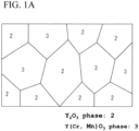
- the present invention it is possible to control the B constant (B(0/1000)) to 2400 K or lower, in the thermistor sintered body formed of a composite structure which includes the Y 2 O 3 phase and the Y(Cr, Mn)O 3 phase or the YMnO 3 phase, by controlling the composition so that 0 ⁇ Cr/Mn ⁇ 1.0 holds, in other words Mn is relatively rich to Cr.
- the present invention can provide a thermistor sintered body that can accurately detect a temperature in a wide temperature range from -50 to 1200°C
- the Y 2 O 3 phase has properties of an electrical insulator, and affects a resistance value of the thermistor sintered body.
- the Y(Cr, Mn)O 3 phase has a property of a semiconductor, and affects a B constant of the thermistor sintered body.
- the thermistor sintered body has a structure of a sintered body, which has the Y 2 O 3 phase of which the resistance value and the B constant are high, and the Y(Cr, Mn)O 3 phase of which the resistance value and the B constant are low.
- the thermistor sintered body is more occupied by the Y 2 O 3 phase than by the Y(Cr, Mn)O 3 phase, and more than 50% by volume to 90% by volume is occupied by the Y 2 O 3 phase, and the remaining portion (10% by volume or more, and less than 50% by volume) is occupied by the Y(Cr, Mn)O 3 phase.
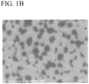
- FIG. 1B a microstructure photograph (4000 magnitudes) of the thermistor sintered body is shown in FIG. 1B .
- the thermistor sintered body typically has a sea-island structure, and has a composite structure in which the Y(Cr, Mn)O 3 phase that forms a sub-phase is dispersed in the Y 2 O 3 phase that forms a main phase.
- the thermistor sintered body preferably contains 60 to 90% by volume of the Y 2 O 3 phase, and more preferably 65 to 75% by volume.
- the Y 2 O 3 phase has an average grain size (d50) of approximately 0.5 to 30 ⁇ m and the Y(Cr, Mn)O 3 phase has an average grain size of approximately 1.0 to 10 ⁇ m.
- Each of the Y 2 O 3 phase and the Y(Cr, Mn)O 3 phase in the thermistor sintered body has been subjected to a composition analysis.
- the YMnO 3 phase is formed instead of the Y(Cr, Mn)O 3 phase, and Ca dissolves in the YMnO 3 phase.
- the thermistor sintered body exhibits thermistor characteristics of NTC, and has the following characteristic: the B constant (B(0/1000)) in a temperature range between 0°C and 1000°C is 2400 K or lower.
- the B constant can be lowered in a wide temperature range.
- the thermistor sintered body according to the present invention can control a resistance value at 1050°C to 0.05 k ⁇ or larger, and preferably to 0.1 k ⁇ or larger; and also can exhibit a resistance value of 100 k ⁇ at room temperature or lower, and preferably below the freezing point, for example, at -40°C or lower.
- the thermistor sintered body it becomes possible to accurately detect a temperature in a wide temperature range ranging from a temperature below the freezing point to 1000°C, more specifically, -50 to 1200°C.
- the thermistor sintered body which has the Y 2 O 3 phase and the Y(Cr, Mn)O 3 phase and corresponds to the form A1 has a chemical composition of Cr, Mn, Ca and Y excluding oxygen, which contains Cr: 3 to 9 mol%, Mn: 5 to 15 mol%, Ca: 1 to 8 mol%, and the balance being unavoidable impurities and Y.
- the thermistor sintered body which includes the Y 2 O 3 phase and the Y(Cr, Mn)O 3 phase and corresponds to the form A2 has a chemical composition of Cr, Mn, Ca and Y excluding oxygen, which contains Cr: ⁇ 5 mol% (excluding 0), Mn: 12 to 18 mol%, Ca: 6 to 18 mol%, and the balance being unavoidable impurities and Y.
- the thermistor sintered body has a composition in which Cr/Mn that is a ratio of Cr to Mn is smaller than 1, in other words, Mn is relatively rich to Cr.
- the thermistor sintered body can lower the B constant by adopting this Mn-rich composition. Because of this, in the thermistor sintered body, in the form A1, the range of Cr is set at 3 to 9 mol%, but on the other hand, the range of Mn is set at 5 to 15 mol%.
- a preferable range of Cr is 5 to 9 mol%, and a more preferable range of Cr is 6 to 8 mol%.
- a preferable range of Mn is 7 to 12 mol%, and a more preferable range of Mn is 8 to 11 mol%.
- the Cr/Mn is 0.4 to 0.9, is more preferable to be 0.6 to 0.9, and is further preferable to be 0.7 to 0.8.
- the Mn-rich composition is adopted; but a range of Cr is ⁇ 5 mol% (excluding 0), and on the other hand, a range of Mn is set at 12 to 23 mol%.
- a preferable range of Cr is 1 to 5 mol%, and a more preferable range of Cr is 2 to 4 mol%.
- a preferable range of Mn is 12 to 20 mol%, and a more preferable range of Mn is 14 to 18 mol%.
- Cr/Mn it is preferable for Cr/Mn to be 0.4 or smaller, and is more preferable to be 0.3 or smaller.
- the form B which adopts the most Mn-rich composition does not contain Cr, and sets a range of Mn at 12 to 18 mol%.
- the preferable range of Mn is similar to that in the form A2.
- Ca has a function of lowering the B constant of the thermistor sintered body by dissolving in the Y(Cr, Mn)O 3 phase. Accordingly, when the amount of Ca is increased, the B constant can be lowered even though the Cr/Mn has been increased.
- a preferable range of Ca is 2 to 7 mol%, and a more preferable range of Ca is 3 to 5 mol%.
- the form A2 and the form B contain 6 to 18 mol% of Ca, which is more as compared with that of the form A1; and a preferable range of Ca is 6 to 14 mol%, and a more preferable range of Ca is 6 to 10 mol%.
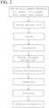
- the production method according to the present embodiment includes steps of weighing of raw material powders, mixing of the raw material powders, drying of the raw material powders, calcining, mixing/grinding after calcining, drying/granulating, compacting and sintering. Each of the steps will be described below in sequence.
- yttrium oxide (Y 2 O 3 ) powder, chromium oxide (Cr 2 O 3 ) powder, manganese oxide (MnO, Mn 2 O 3 , Mn 3 O 4 or the like) powder and CaCO 3 powder are used as raw material powders.
- chromium oxide (Cr 2 O 3 ) powder is removed.
- the above described raw material powders are weighed so as to form the above described chemical composition.
- the Y 2 O 3 powder contributes to the formation of a Y 2 O 3 phase
- the Y 2 O 3 powder, the Cr 2 O 3 powder and the Mn 3 O 4 powder contribute to the formation of a Y(Cr, Mn)O 3 phase
- the CaCO 3 powder functions as a sintering aid; and in addition, dissolves in the Y(Cr, Mn)O 3 phase in a form of Ca, and contributes to lowering a B constant.
- powders are used of which the purities are 98% or higher, preferably 99% or higher, and more preferably 99.9% or higher, in order to obtain a thermistor sintered body having high characteristics.
- the particle size of the raw material powder is not limited as long as calcination proceeds, but can be selected from a range of 0.1 to 6.0 ⁇ m by an average particle size (d50).
- the Y 2 O 3 powder, the Cr 2 O 3 powder, the Mn 3 O 4 powder and the CaCO 3 powder which have been weighed by predetermined amounts are mixed.
- the mixing can be performed, for example, by using a ball mill to mix the mixed powders converted into a slurry by addition of water.
- a mixer other than the ball mill can also be used for the mixing.
- the mixed powder for calcination which has been dried, is calcined.
- a calcined body having a composite structure of the Y 2 O 3 phase and the Y(Cr, Mn)O 3 phase is obtained from the Y 2 O 3 powder, the Cr 2 O 3 powder, the Mn 3 O 4 powder and the CaCO 3 powder.
- the calcination is performed by placing the mixed powder for calcination, for example, in a crucible, and holding the mixed powder in a temperature range of 800 to 1300°C in the air. If the calcination temperature is lower than 800°C, the formation of the composite structure is insufficient, and if the calcination temperature exceeds 1300°C, there is a possibility that a sintering density lowers and/or the stability of the resistance value lowers. Therefore, the holding temperature in the calcination is set in the range of 800 to 1300°C.
- a holding time period in the calcination should be appropriately set according to the holding temperature, but if the holding temperature is in the above described temperature range, the purpose of the calcination can be achieved by the holding time period of approximately 0.5 to 100 hours.
- the calcined powder is mixed and pulverized.
- the powders can be converted into slurry by addition of water, and be mixed and pulverized with the use of a ball mill, in the same manner as before the calcination.
- the granulated powder after the calcination is compacted into a predetermined shape.
- press compacting with the use of a die, and besides a cold isostatic press (CIP) can be used.
- CIP cold isostatic press
- the sintering is performed by a procedure of holding the temperature range of 1400 to 1650°C in the air. If the sintering temperature is lower than 1400°C, the formation of the composite structure is insufficient; and if it exceeds 1650°C, the sintered body melts, and/or a reaction occurs with a sintering crucible and/or the like.
- the holding time period in the sintering should be appropriately set according to the holding temperature, but if the holding temperature is in the above described temperature range, a dense sintered body can be obtained by a holding time period of approximately 0.5 to 200 hours.
- the thermistor sintered body is annealed by being held, for example, at 1000°C in the air.
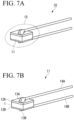
- thermoistor 10 A specific example of a thermistor 10 will be described to which the thermistor sintered body obtained in the above described way is applied.
- the thermistor 10 includes a thermistor element 11 and a covering layer 15.
- the thermistor element 11 is used together with a detection circuit for extracting a change of a resistance value as a change of voltage, thereby detects a temperature of an environment in which the thermistor element 11 is placed, and generates a temperature detection signal consisting of an electrical signal.
- the covering layer 15 seals the thermistor element 11 to keep the thermistor element 11 in an airtight state, thereby prevents the occurrence of chemical and physical changes of the thermistor sintered body in particular, based on the environmental conditions, and also mechanically protects the thermistor element 11.
- the thermistor element 11 in this example includes a flat plate-like thermistor sintered body, electrodes 12A and 12B, connection electrodes 13A and 13B, and lead wires 14A and 14B.
- the electrodes 12A and 12B are each formed in a film shape on the whole area of both the front and rear surfaces of the plate-like thermistor sintered body.
- the electrodes 12A and 12B are formed from platinum (Pt) or another noble metal.
- the electrodes 12A and 12B are formed as thick films or thin films.
- the thick film electrodes 12A and 12B are formed by applying a paste which has been prepared by mixing an organic binder with platinum powder, to both the front and rear surfaces of the thermistor sintered body, and by drying and then sintering the paste.
- the thin film electrode can be formed by vacuum deposition or sputtering.
- the thermistor sintered body on which the electrodes 12A and 12B have been formed is worked into a predetermined dimension.
- connection electrodes 13A and 13B are formed of metal films which are formed on the surfaces of the electrodes 12A and 12B, respectively. Also the connection electrodes 13A and 13B are formed from platinum (Pt) or another noble metal.
- the lead wires 14A and 14B are electrically and mechanically connected to the electrodes 12A and 12B via the connection electrodes 13A and 13B, respectively.
- the other ends of the lead wires 14A and 14B are connected to an external detection circuit.
- the lead wires 14A and 14B are formed of a wire material which has heat resistance and is formed from, for example, platinum or an alloy of platinum and iridium (Ir).
- the lead wires 14A and 14B are connected to the electrodes 12A and 12B in the following way.
- a paste containing a platinum powder which will form the connection electrodes 13A and 13B is applied to one end sides of the lead wires 14A and 14B beforehand.
- the platinum paste is dried in a state in which sides of the lead wires 14A and 14B, to which the platinum paste has been applied, are in contact with the electrodes 12A and 12B, respectively, and then the platinum powder is sintered.
- the glass can be used which contains, for example, SiO 2 , CaO, SrO, BaO, Al 2 O 3 and SnO 2 as the raw materials.
- the thermistor element 11 and the one end sides of the lead wires 14A and 14B are sealed.
- a method for sealing the thermistor sintered body and the like by the covering layer 15 can be arbitrarily selected; and it is possible to seal the thermistor sintered body and the like by covering the thermistor sintered body and the like with, for example, a glass tube which is made from glass and becomes the covering layer 15, and then by melting the glass tube.
- the thermistor 10 is preferably subjected to annealing treatment, after having been sealed by glass and cooled. By this annealing treatment, it becomes possible to prevent the resistance of the thermistor element 11 from decreasing.
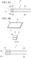
- the thermistor 20 includes a thermistor element 21 and a covering layer 25 as shown in FIG. 8A , and is similar to the thermistor 10 in appearance.
- the thermistor element 21 and the covering layer 25 have similar functions to those of the thermistor element 11 and the covering layer 15 of the thermistor 10, respectively.
- the thermistor element 21 in this example includes a flat plate-like thermistor sintered body, electrodes 22A and 22B, connection electrodes 23A and 23B, and lead wires 24A and 24B.
- the thermistor element 21 has features in portions of the thermistor sintered body and the electrodes 22A and 22B, as compared with the thermistor element 11. As shown in a middle stage of FIG. 8B , the thermistor sintered body and the electrodes 22A and 22B constitute a thermistor chip 33, in the thermistor element 21.
- the thermistor chip 33 is produced in the following way.
- an ethyl cellulose-based binder is mixed, and the mixture is formed into a sheet shape.
- the conditions of the calcination are as previously described.
- a predetermined dimension of the sheet is punched from the formed sheet, and is sintered.
- the conditions of the sintering are as previously described.
- a wafer obtained by the sintering is polished and a wafer 31 having a predetermined thickness is obtained as is shown in the middle stage of FIG. 8B .
- a paste for forming an electrode is applied to both the front and rear surfaces of the polished wafer 31 (thermistor sintered body) by printing, and then is sintered; and a wafer 30 is obtained on which electrode films have been formed.
- the electro-conductive material to be contained in the paste is selected from platinum (Pt) and other noble metals. When the platinum has been selected, the sintering is performed at approximately 1300°C.
- the wafer 30 is cut so as to have a predetermined dimension, as shown in the middle stage of FIG. 8B , and thereby the thermistor chip 33 is obtained which has the film-like electrodes 22A and 22B formed on the front and back surfaces, respectively.
- the lead wires 24A and 24B are joined to the electrodes 22A and 22B on both the front and rear surfaces of the thermistor sintered body, respectively, with the use of a Pt paste, then the resultant thermistor sintered body is subjected to baking treatment to have the connection electrodes 23A and 23B formed thereon, and the thermistor element 21 shown in the lower part of FIG. 8B is produced.
- the covering layer 25 is formed; and for the covering layer 25, the previously described glass can be used, or the covering material can also be used which is formed of a constituent material similar to the thermistor sintered body.
- a composite oxide can be used that has been obtained by sintering a powder which has been obtained by calcining Y 2 O 3 , Cr 2 O 3 and Mn 3 O 4 disclosed in the above mentioned JP 2006-108221 A and a B 2 O 3 powder.
- the covering layer of the thermistor sintered body in the present invention can be arbitrarily selected as long as the purpose can be achieved.
- Example 1 corresponds to the previously described form A1.
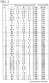
- Raw material powders having the following average particle sizes were prepared, and thermistor sintered bodies having various compositions shown in FIG. 3 were produced according to the above described production steps.
- Nos. 1 to 35 are samples in which Cr/Mn is smaller than 1 and Mn is rich relative to Cr; and Nos. 36 and 37 are samples in which Cr/Mn is 1 or larger, in other words, Cr and Mn are in equal amounts, or Cr is rich.
- Calcination was performed under conditions of 1000°C and 24 hours, and sintering was performed under conditions of 1500°C and 24 hours, both in the air.
- CaCO 3 powder 2.0 ⁇ m
- the B constant was determined for each of the obtained sintered bodies. The results are collectively shown in FIG. 3 .
- the B constants in FIG. 3 are values between 25°C and 50°C (B25/50).
- the B constants in a plurality of temperature ranges were determined by a procedure of measuring resistance values in the range of -40°C to 1050°C, about several samples in FIG. 3 .
- the B constants were determined about the following four types of which the Rn and Rm were different in the following expression. Incidentally, the B constants were similarly determined for Sample Nos. 36 and 37, which corresponded to Comparative Example.
- B m / n lnRm ⁇ lnRn / 1 / Tm ⁇ 1 / Tn
- B(0/1000) of the Samples Nos. 3, 9, 10, 11, 13 and 19 which correspond to the present invention are 2400 K or lower, and the B constants are controlled to be lower in a wide temperature range of - 40°C to 1000°C than those of Samples Nos. 36 and 37, which correspond to Comparative Example.
- B(-40/25), B(25/600) and B(600/1000) are the B constants which were determined by dividing the range of -40°C to 1000°C into a low temperature range (-40°C to 25°C), a middle temperature range (25°C to 600°C) and a high temperature range (600°C to 1000°C).
- the resistance values at 1050°C 1000°C, in case of Comparative Example
- the resistance value at 1050°C can be increased to 0.05 k ⁇ or larger, and further 0.1 k ⁇ or larger.
- Sample No. 10 of which the resistance value at 1050°C is 0.1 k ⁇ or larger the resistance value does not fall below 0.05 k ⁇ even at 1200°C; and Sample No. 10 can achieve accurate temperature detection at 1200°C.
- a temperature at which a resistance value of 100 k ⁇ is exhibited is also shown, but the thermistor sintered body in the present invention can exhibit a resistance value of 100 k ⁇ at a temperature equal to or lower than room temperature such as -30°C and even -40°C.
- the graphs of FIG. 5A and FIG. 5B show a relationship between a temperature and a resistance value (R-T curve) of Samples Nos. 3, 11, 36 and 37 in the range of -40°C to 1050°C. However, the temperatures of Sample Nos. 36 and 37 are 1000°C or lower. The above description is similar also in FIG. 6A and FIG. 6B which will be described later.
- the R-T curve is positioned in a middle of the R-T curves of Sample No. 36 and Sample No. 37.
- Sample No. 3 and Sample No. 11 show a resistance value equivalent to Sample No. 36 which is directed to a low temperature to a medium temperature, at a low temperature of -40°C, and show a resistance value equivalent to Sample No. 37 which is directed to a medium temperature to a high temperature, at a high temperature of 1050°C.
- Sample No. 3 and Sample No. 11 enable the accurate temperature detection in a wide temperature range from the low temperature to the high temperature.
- the graphs of FIG. 6A to FIG. 6B show R-T curves in the range of -40°C to 1050°C of Samples Nos. 10, 13, 36 and 37.
- Sample No. 10 has a high resistance value in a range from a medium temperature to a high temperature, enables the temperature detection in a wide temperature range from a low temperature to a high temperature, and is suitable for accurately detecting a temperature particularly in the high temperature range.
- Example 2 corresponds to the previously described form A2 and form B.
- Example 2 is further richer in Mn relative to Cr than Example 1, and includes even a thermistor sintered body (form B) which does not contain Cr.
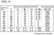
- Thermistor sintered bodies having chemical compositions shown in FIG. 9 were produced by a similar method to that in Example 1.
- Samples Nos. 38 to 41 in FIG. 9 in which Cr/Mn is 0.25, is richer in Mn than Sample No. 7 in which Mn is richest in Example 1 and Cr/Mn is 0.462.
- Samples Nos. 42 to 44 in FIG. 9 do not contain Cr, and can be referred to as examples in which Mn is richest relative to Cr.
- Samples Nos. 38 to 44 contain Ca in the range of 8 to 16 mol%, and contain more Ca than Sample No. 19 and the like that contain 4.5 mol% of Ca, which is highest in Example 1.
- a thermistor sintered body which includes the Y 2 O 3 phase and the Y(Cr, Mn)O 3 phase and contains Ca has been recognized in the following way.
- a low B constant can be obtained in a sintered body that includes the Y 2 O 3 phase and the Y(Cr, Mn)O 3 phase, in a range in which Cr/Mn is in the vicinity of 1.
- Mn exceeds this range and becomes rich, the B constant becomes high.
- a low B constant can be obtained in the sintered body which includes the Y 2 O 3 phase and the Y(Cr, Mn)O 3 phase, in a range in which the content of Ca is in the vicinity of 5 mol%.
- the B constant becomes high.
- the B constants of Sample Nos. 38 to 44 are high in which Mn is rich relative to Cr and Ca exceeds 5 mol%.
- the B constants of Samples Nos. 38 to 44 are low. This is understood to be because crystal structures of these samples are concerned.
- the thermistor sintered body which includes the Y 2 O 3 phase and the Y(Cr, Mn)O 3 phase has the crystal structure of an orthorhombic crystal system
- the thermistor sintered body exhibits stable characteristics (B constant) until reaching a high temperature.
- YMnO 3 which does not contain Cr has a crystal structure of a hexagonal crystal system, and accordingly shows a high B constant.
- YMnO 3 becomes the Y(Cr, Mn)O 3 phase by containing Cr, the crystal structure becomes the orthorhombic crystal system.
- the crystal structure of the orthorhombic crystal system can be obtained by containing Ca in an amount exceeding conventional recognition, and the B constant can be lowered.
- the crystal structures of Samples Nos. 38, 41, 42 and 44 in Example 2 are the orthorhombic crystal system as are those of Samples Nos. 1, 6 and the like in Example 1.
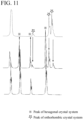
- the bottom is a chart of a sintered body which is formed of a composite phase of the Y 2 O 3 phase and the YMnO 3 phase and does not contain Ca
- the second from the bottom is a chart of a sintered body which is formed of the composite phase of the Y 2 O 3 phase and the YMnO 3 phase and contains 3.5 mol% of Ca
- the third from the bottom is a chart of a sintered body which is formed of the composite phase of the Y 2 O 3 phase and the YMnO 3 phase and contains 22 mol% of Ca.
- FIG. 11 An enlarged view of a portion in which these three charts are surrounded by a rectangle in FIG. 10 is shown in FIG. 11 .
- a single-phase sintered body of the YMnO 3 which does not contain Ca, has a crystal structure of only a hexagonal crystal system.
- a peak of the crystal structure of the orthorhombic crystal system is detected, but a peak of the crystal structure of the hexagonal crystal system is detected; and the sintered body has a crystal structure in which the orthorhombic crystal system and the hexagonal crystal system are mixed.
- a peak of the crystal structure of the hexagonal crystal system disappears; and the sintered body is formed of a crystal structure of only the orthorhombic crystal system.
- the single-phase sintered body of the YMnO 3 has the crystal structure of the hexagonal crystal system.
- the crystal structure of the orthorhombic crystal system can be obtained by containing a considerable amount of, here 22 mol% of Ca, even though the sintered body is the single-phase sintered body of the YMnO 3 .
- the reason why the B constant of Example 2 (Sample Nos. 38 to 44) is low is attributed to that the crystal structure is the orthorhombic crystal system.
- the thermistor sintered body having a composite structure which includes the Y 2 O 3 phase and the Y(Cr, Mn)O 3 phase, or the Y 2 O 3 phase and the YMnO 3 phase can control the B constant to be low and can control the lowering of the resistance value particularly in a high temperature range, by controlling Mn to be rich relative to Cr. Accordingly, according to the present invention, the accurate temperature detection can be achieved in a wide temperature range.
- the thermistor sintered body and the thermistor of the present invention can be used over a wide temperature range from -50°C to approximately 1200°C, and accordingly can be widely used as a temperature sensor for automotive exhaust-gas treatment devices, and for the measurement of a high temperature in a water heater, a boiler, an oven range, a stove and the like.
- the thermistor sintered body of the present invention is formed of only a crystal structure of the orthorhombic crystal system, but it is not excluded that a crystal structure of the hexagonal crystal system exists.
- the thermistor sintered body corresponds to the thermistor sintered body of the present invention.
Landscapes
- Engineering & Computer Science (AREA)
- Chemical & Material Sciences (AREA)
- Microelectronics & Electronic Packaging (AREA)
- Ceramic Engineering (AREA)
- Manufacturing & Machinery (AREA)
- Physics & Mathematics (AREA)
- Electromagnetism (AREA)
- Materials Engineering (AREA)
- Structural Engineering (AREA)
- Organic Chemistry (AREA)
- Inorganic Chemistry (AREA)
- Thermistors And Varistors (AREA)
- Compositions Of Oxide Ceramics (AREA)
Claims (10)
- Corps fritté à thermistance comprenant un corps fritté qui comprend :plus de 50 % en volume à 90 % en volume d'une phase Y2O3 en tant que phase principale ;10 % en volume à moins de 50 % en volume d'une phase Y(Cr, Mn)O3 en tant que sous-phase dispersée dans la phase principale ; etdu Ca dissous dans la phase Y(Cr, Mn)O3,caractérisé en ce que le corps fritté a une composition dans laquelle 0 ≤ Cr/Mn < 1,0 de sorte que le corps fritté est riche en Mn par rapport au Cr,le corps fritté a une structure cristalline d'un système cristallin orthorhombique, etle corps fritté satisfait à l'une des conditions (a) à (b) suivantes :(a) le corps fritté comprend une phase Y(Cr, Mn)O3 en tant que sous-phase, et comprend 3 à 9 % en moles de Cr, 5 à 15 % en moles de Mn, 1 à 8 % en moles de Ca, et le reste étant du Y, où Cr/Mn est compris entre 0,4 et 0, 9 et le calcul des pourcentages molaires de Cr, Mn, Ca et Y ne tient pas compte de la quantité d'oxygène comprise dans le corps fritté ; ou(b) le corps fritté comprend une phase Y(Cr, Mn)O3 en tant que sous-phase, et comprend ≤5 % en moles (à l'exclusion de 0) de Cr, 12 à 23 % en moles de Mn, 6 à 18 % en moles de Ca, et le reste de Y, dans lequel Cr/Mn est compris entre 0, 5 ou moins (à l'exclusion de 0) et le calcul des pourcentages molaires de Cr, Mn, Ca et Y ne tient pas compte de la quantité d'oxygène contenue dans le corps fritté ;de telle sorte qu'une constante B (B(0/1000)) du corps fritté déterminée par l'expression suivante soit inférieure ou égale à 2400 K et supérieure ou égale à 2185 K :
 ln : logarithme naturel,Rm : valeur de résistance à 273 K,Rn : valeur de résistance à 1273 K,Tm : 273 K, etTn : 1273 K.
 - Corps fritté thermistor selon la revendication 1, dans lequel le corps fritté satisfait à la condition (a).
- Corps fritté thermistor selon la revendication 1, dans lequel le corps fritté satisfait à la condition (b).
- Corps fritté thermistor selon l'une quelconque des revendications 1 à 3, dans lequel une constante B (B(-40/25)) du corps fritté déterminée par l'expression suivante est inférieure ou égale à 2200 K :
 ln : logarithme naturel,Rm : valeur de résistance à 233 K,Rn : valeur de résistance à 298 K,Tm : 233 K, etTn : 298 K.
 - Corps fritté de thermistance selon l'une quelconque des revendications 1 à 3, dans lequel une constante B (B(25/600)) du corps fritté déterminée par l'expression suivante est inférieure ou égale à 2300 K :
 ln : logarithme naturel,Rm : valeur de résistance à 298 K,Rn : valeur de résistance à 873 K,Tm : 298 K, etTn : 873 K.
 - Corps fritté thermistor selon l'une quelconque des revendications 1 à 3, dans lequel une constante B (B(600/1000)) du corps fritté déterminée par l'expression suivante est inférieure ou égale à 2800 K :
 ln : logarithme naturel,Rm : valeur de résistance à 873 K,Rn : valeur de résistance à 1273 K,Tm : 873 K, etTn : 1273 K.
 - Corps fritté thermistor selon l'une quelconque des revendications 1 à 6, dans lequel une valeur de résistance à 1050 °C est de 0,05 kΩ ou plus.
- Corps fritté thermistor selon l'une quelconque des revendications 1 à 7, dans lequel une valeur de résistance de 100 kΩ est présentée à température ambiante ou inférieure.
- Élément thermistance (11, 21) comprenant :un corps thermosensible ;une paire de fils conducteurs (14A, 14B, 24A, 24B) connectés électriquement au corps thermosensible ; etune couche de recouvrement (15, 25) recouvrant le corps thermosensible,dans lequel le corps thermosensible comprend le corps fritté de thermistance selon l'une quelconque des revendications 1 à 8.
- Élément thermistance (11, 21) selon la revendication 9, dans lequel la couche de recouvrement (15, 25) est en verre.
Applications Claiming Priority (2)
| Application Number | Priority Date | Filing Date | Title |
|---|---|---|---|
| JP2017120348 | 2017-06-20 | ||
| PCT/JP2018/017149 WO2018235432A1 (fr) | 2017-06-20 | 2018-04-27 | Corps fritté de thermistor et élément de thermistor |
Publications (3)
| Publication Number | Publication Date |
|---|---|
| EP3553796A1 EP3553796A1 (fr) | 2019-10-16 |
| EP3553796A4 EP3553796A4 (fr) | 2020-12-16 |
| EP3553796B1 true EP3553796B1 (fr) | 2025-06-04 |
Family
ID=64737121
Family Applications (1)
| Application Number | Title | Priority Date | Filing Date |
|---|---|---|---|
| EP18820706.2A Active EP3553796B1 (fr) | 2017-06-20 | 2018-04-27 | Corps fritté de thermistor et élément de thermistor |
Country Status (5)
| Country | Link |
|---|---|
| US (1) | US10643768B2 (fr) |
| EP (1) | EP3553796B1 (fr) |
| JP (1) | JP6530569B2 (fr) |
| CN (1) | CN110024053B (fr) |
| WO (1) | WO2018235432A1 (fr) |
Families Citing this family (4)
| Publication number | Priority date | Publication date | Assignee | Title |
|---|---|---|---|---|
| JP6675050B1 (ja) * | 2018-10-31 | 2020-04-01 | 株式会社芝浦電子 | サーミスタ焼結体および温度センサ素子 |
| WO2021100312A1 (fr) * | 2019-11-21 | 2021-05-27 | 株式会社芝浦電子 | Capteur de température infrarouge, dispositif de détection de température et dispositif de formation d'image |
| JP7451277B2 (ja) * | 2020-04-17 | 2024-03-18 | 株式会社芝浦電子 | サーミスタ焼結体および温度センサ素子 |
| CN112979280A (zh) * | 2021-03-04 | 2021-06-18 | 咸阳师范学院 | 一种Cr掺杂YMnO3磁性材料及其退火方法 |
Citations (2)
| Publication number | Priority date | Publication date | Assignee | Title |
|---|---|---|---|---|
| JPH0562805A (ja) * | 1991-08-29 | 1993-03-12 | Nippondenso Co Ltd | 高温用サーミスタ材料 |
| JPH1070011A (ja) * | 1996-03-29 | 1998-03-10 | Denso Corp | 高温用サーミスタ材料の製造方法及び高温用サーミスタ |
Family Cites Families (18)
| Publication number | Priority date | Publication date | Assignee | Title |
|---|---|---|---|---|
| US3975307A (en) * | 1974-10-09 | 1976-08-17 | Matsushita Electric Industrial Co., Ltd. | PTC thermistor composition and method of making the same |
| JP3141719B2 (ja) | 1995-01-18 | 2001-03-05 | 株式会社村田製作所 | 負の抵抗温度特性を有する半導体セラミックとそれを用いた半導体セラミック部品 |
| US5749656A (en) * | 1995-08-11 | 1998-05-12 | General Motors Corporation | Thermal probe assembly with mold-over crimp sensor packaging |
| JPH09223602A (ja) * | 1996-02-15 | 1997-08-26 | Toyota Central Res & Dev Lab Inc | サーミスタ組成物 |
| US5879750A (en) * | 1996-03-29 | 1999-03-09 | Denso Corporation | Method for manufacturing thermistor materials and thermistors |
| JP2002124403A (ja) * | 2000-08-10 | 2002-04-26 | Nippon Soken Inc | 耐還元性サーミスタ素子とその製造方法および温度センサ |
| CN100411068C (zh) * | 2003-10-21 | 2008-08-13 | 上海春叶实业有限公司 | 多层片式负温度系数热敏电阻及其制造方法 |
| JP3806434B2 (ja) | 2004-04-01 | 2006-08-09 | 株式会社芝浦電子 | 高温用サーミスタ |
| JP2006108221A (ja) | 2004-10-01 | 2006-04-20 | Shibaura Electronics Co Ltd | 高温耐熱型サーミスタ |
| KR101155688B1 (ko) * | 2005-04-11 | 2012-06-12 | 니뽄 도쿠슈 도교 가부시키가이샤 | 도전성 산화물 소결체, 도전성 산화물 소결체를 이용한서미스터 소자, 및 서미스터 소자를 이용한 온도 센서 |
| DE602007004871D1 (de) * | 2007-12-21 | 2010-04-01 | Vishay Resistors Belgium Bvba | Stabiler Thermistor |
| JP2010025603A (ja) | 2008-07-16 | 2010-02-04 | Nippon Soken Inc | 複合温度センサ素子、及びその製造方法 |
| JP2010225903A (ja) | 2009-03-24 | 2010-10-07 | Tateyama Kagaku Kogyo Kk | サーミスタ用組成物とサーミスタ素子及びその製造方法 |
| US9164114B2 (en) * | 2011-04-19 | 2015-10-20 | Roche Molecular Systems, Inc. | Supply unit for continuous loading |
| JP6010473B2 (ja) | 2012-04-10 | 2016-10-19 | 日本特殊陶業株式会社 | 導電性酸化物焼結体、サーミスタ素子及び温度センサ |
| KR101355397B1 (ko) * | 2012-05-18 | 2014-01-28 | 가우스텍 주식회사 | 센서소자용 조성물, 이를 포함하는 온도센서 및 이의 제조방법 |
| KR101908775B1 (ko) * | 2015-04-06 | 2018-10-16 | 니뽄 도쿠슈 도교 가부시키가이샤 | 도전성 산화물 소결체, 그것을 사용한 서미스터 소자 및 온도 센서 |
| JP2017191856A (ja) * | 2016-04-13 | 2017-10-19 | 日本特殊陶業株式会社 | サーミスタ素子及びその製造方法 |
-
2018
- 2018-04-27 EP EP18820706.2A patent/EP3553796B1/fr active Active
- 2018-04-27 CN CN201880004718.4A patent/CN110024053B/zh active Active
- 2018-04-27 JP JP2018550003A patent/JP6530569B2/ja active Active
- 2018-04-27 US US16/475,944 patent/US10643768B2/en active Active
- 2018-04-27 WO PCT/JP2018/017149 patent/WO2018235432A1/fr not_active Ceased
Patent Citations (2)
| Publication number | Priority date | Publication date | Assignee | Title |
|---|---|---|---|---|
| JPH0562805A (ja) * | 1991-08-29 | 1993-03-12 | Nippondenso Co Ltd | 高温用サーミスタ材料 |
| JPH1070011A (ja) * | 1996-03-29 | 1998-03-10 | Denso Corp | 高温用サーミスタ材料の製造方法及び高温用サーミスタ |
Also Published As
| Publication number | Publication date |
|---|---|
| CN110024053A (zh) | 2019-07-16 |
| US20190348201A1 (en) | 2019-11-14 |
| JPWO2018235432A1 (ja) | 2019-06-27 |
| JP6530569B2 (ja) | 2019-06-12 |
| WO2018235432A1 (fr) | 2018-12-27 |
| US10643768B2 (en) | 2020-05-05 |
| EP3553796A4 (fr) | 2020-12-16 |
| CN110024053B (zh) | 2021-03-09 |
| EP3553796A1 (fr) | 2019-10-16 |
Similar Documents
| Publication | Publication Date | Title |
|---|---|---|
| EP3553796B1 (fr) | Corps fritté de thermistor et élément de thermistor | |
| CN105967674A (zh) | 一种铬掺杂铝酸镁高温热敏电阻材料及其制备方法 | |
| JPH11322415A (ja) | チタン酸バリウム粉末、および半導体セラミック、ならびに半導体セラミック素子 | |
| US12385792B2 (en) | Thermistor sintered body and temperature sensor element | |
| JP2021106178A (ja) | 温度センサ素子 | |
| JP6675050B1 (ja) | サーミスタ焼結体および温度センサ素子 | |
| US4743881A (en) | Ceramic temperature sensor | |
| US4647895A (en) | Ceramic temperature sensor | |
| JP2004221519A (ja) | サーミスタ素子用焼結体及びその製造方法、並びにサーミスタ素子、温度センサ | |
| CN117897783B (zh) | 温度传感器元件及温度传感器 | |
| JP7389306B1 (ja) | 温度センサ素子および温度センサ | |
| EP3780022B1 (fr) | Corps fritté de thermistor et élément de capteur de température | |
| EP4579691A1 (fr) | Élément de thermistance et procédé de production associé | |
| WO2024004870A1 (fr) | Élément de capteur de température et capteur de température | |
| JP7473753B1 (ja) | 温度センサ素子および温度センサ | |
| WO2024004845A1 (fr) | Élément de capteur de température et capteur de température | |
| JPH0769725A (ja) | セラミック製発熱素子 |
Legal Events
| Date | Code | Title | Description |
|---|---|---|---|
| STAA | Information on the status of an ep patent application or granted ep patent |
Free format text: STATUS: THE INTERNATIONAL PUBLICATION HAS BEEN MADE |
|
| PUAI | Public reference made under article 153(3) epc to a published international application that has entered the european phase |
Free format text: ORIGINAL CODE: 0009012 |
|
| STAA | Information on the status of an ep patent application or granted ep patent |
Free format text: STATUS: REQUEST FOR EXAMINATION WAS MADE |
|
| 17P | Request for examination filed |
Effective date: 20190710 |
|
| AK | Designated contracting states |
Kind code of ref document: A1 Designated state(s): AL AT BE BG CH CY CZ DE DK EE ES FI FR GB GR HR HU IE IS IT LI LT LU LV MC MK MT NL NO PL PT RO RS SE SI SK SM TR |
|
| AX | Request for extension of the european patent |
Extension state: BA ME |
|
| DAV | Request for validation of the european patent (deleted) | ||
| DAX | Request for extension of the european patent (deleted) | ||
| A4 | Supplementary search report drawn up and despatched |
Effective date: 20201116 |
|
| RIC1 | Information provided on ipc code assigned before grant |
Ipc: H01C 7/00 20060101ALI20201110BHEP Ipc: C04B 35/505 20060101ALI20201110BHEP Ipc: H01C 7/06 20060101AFI20201110BHEP Ipc: H01C 7/04 20060101ALI20201110BHEP |
|
| STAA | Information on the status of an ep patent application or granted ep patent |
Free format text: STATUS: EXAMINATION IS IN PROGRESS |
|
| 17Q | First examination report despatched |
Effective date: 20210729 |
|
| REG | Reference to a national code |
Ref country code: DE Ref legal event code: R079 Free format text: PREVIOUS MAIN CLASS: H01C0007040000 Ipc: H01C0007000000 Ref country code: DE Ref legal event code: R079 Ref document number: 602018082440 Country of ref document: DE Free format text: PREVIOUS MAIN CLASS: H01C0007040000 Ipc: H01C0007000000 |
|
| GRAP | Despatch of communication of intention to grant a patent |
Free format text: ORIGINAL CODE: EPIDOSNIGR1 |
|
| STAA | Information on the status of an ep patent application or granted ep patent |
Free format text: STATUS: GRANT OF PATENT IS INTENDED |
|
| RIC1 | Information provided on ipc code assigned before grant |
Ipc: C04B 35/505 20060101ALI20250304BHEP Ipc: H01C 17/065 20060101ALI20250304BHEP Ipc: H01C 7/06 20060101ALI20250304BHEP Ipc: H01C 7/04 20060101ALI20250304BHEP Ipc: H01C 7/00 20060101AFI20250304BHEP |
|
| INTG | Intention to grant announced |
Effective date: 20250314 |
|
| GRAS | Grant fee paid |
Free format text: ORIGINAL CODE: EPIDOSNIGR3 |
|
| GRAA | (expected) grant |
Free format text: ORIGINAL CODE: 0009210 |
|
| STAA | Information on the status of an ep patent application or granted ep patent |
Free format text: STATUS: THE PATENT HAS BEEN GRANTED |
|
| AK | Designated contracting states |
Kind code of ref document: B1 Designated state(s): AL AT BE BG CH CY CZ DE DK EE ES FI FR GB GR HR HU IE IS IT LI LT LU LV MC MK MT NL NO PL PT RO RS SE SI SK SM TR |
|
| REG | Reference to a national code |
Ref country code: GB Ref legal event code: FG4D |
|
| REG | Reference to a national code |
Ref country code: CH Ref legal event code: EP |
|
| REG | Reference to a national code |
Ref country code: DE Ref legal event code: R096 Ref document number: 602018082440 Country of ref document: DE |
|
| REG | Reference to a national code |
Ref country code: IE Ref legal event code: FG4D |
|
| REG | Reference to a national code |
Ref country code: NL Ref legal event code: MP Effective date: 20250604 |
|
| PG25 | Lapsed in a contracting state [announced via postgrant information from national office to epo] |
Ref country code: FI Free format text: LAPSE BECAUSE OF FAILURE TO SUBMIT A TRANSLATION OF THE DESCRIPTION OR TO PAY THE FEE WITHIN THE PRESCRIBED TIME-LIMIT Effective date: 20250604 Ref country code: ES Free format text: LAPSE BECAUSE OF FAILURE TO SUBMIT A TRANSLATION OF THE DESCRIPTION OR TO PAY THE FEE WITHIN THE PRESCRIBED TIME-LIMIT Effective date: 20250604 |
|
| REG | Reference to a national code |
Ref country code: LT Ref legal event code: MG9D |
|
| PG25 | Lapsed in a contracting state [announced via postgrant information from national office to epo] |
Ref country code: GR Free format text: LAPSE BECAUSE OF FAILURE TO SUBMIT A TRANSLATION OF THE DESCRIPTION OR TO PAY THE FEE WITHIN THE PRESCRIBED TIME-LIMIT Effective date: 20250905 Ref country code: NO Free format text: LAPSE BECAUSE OF FAILURE TO SUBMIT A TRANSLATION OF THE DESCRIPTION OR TO PAY THE FEE WITHIN THE PRESCRIBED TIME-LIMIT Effective date: 20250904 |
|
| PG25 | Lapsed in a contracting state [announced via postgrant information from national office to epo] |
Ref country code: PL Free format text: LAPSE BECAUSE OF FAILURE TO SUBMIT A TRANSLATION OF THE DESCRIPTION OR TO PAY THE FEE WITHIN THE PRESCRIBED TIME-LIMIT Effective date: 20250604 |
|
| PG25 | Lapsed in a contracting state [announced via postgrant information from national office to epo] |
Ref country code: BG Free format text: LAPSE BECAUSE OF FAILURE TO SUBMIT A TRANSLATION OF THE DESCRIPTION OR TO PAY THE FEE WITHIN THE PRESCRIBED TIME-LIMIT Effective date: 20250604 |
|
| PG25 | Lapsed in a contracting state [announced via postgrant information from national office to epo] |
Ref country code: HR Free format text: LAPSE BECAUSE OF FAILURE TO SUBMIT A TRANSLATION OF THE DESCRIPTION OR TO PAY THE FEE WITHIN THE PRESCRIBED TIME-LIMIT Effective date: 20250604 |
|
| PG25 | Lapsed in a contracting state [announced via postgrant information from national office to epo] |
Ref country code: RS Free format text: LAPSE BECAUSE OF FAILURE TO SUBMIT A TRANSLATION OF THE DESCRIPTION OR TO PAY THE FEE WITHIN THE PRESCRIBED TIME-LIMIT Effective date: 20250904 |
|
| PG25 | Lapsed in a contracting state [announced via postgrant information from national office to epo] |
Ref country code: LV Free format text: LAPSE BECAUSE OF FAILURE TO SUBMIT A TRANSLATION OF THE DESCRIPTION OR TO PAY THE FEE WITHIN THE PRESCRIBED TIME-LIMIT Effective date: 20250604 |
|
| PG25 | Lapsed in a contracting state [announced via postgrant information from national office to epo] |
Ref country code: NL Free format text: LAPSE BECAUSE OF FAILURE TO SUBMIT A TRANSLATION OF THE DESCRIPTION OR TO PAY THE FEE WITHIN THE PRESCRIBED TIME-LIMIT Effective date: 20250604 |
|
| PG25 | Lapsed in a contracting state [announced via postgrant information from national office to epo] |
Ref country code: PT Free format text: LAPSE BECAUSE OF FAILURE TO SUBMIT A TRANSLATION OF THE DESCRIPTION OR TO PAY THE FEE WITHIN THE PRESCRIBED TIME-LIMIT Effective date: 20251006 |
|
| REG | Reference to a national code |
Ref country code: AT Ref legal event code: MK05 Ref document number: 1801210 Country of ref document: AT Kind code of ref document: T Effective date: 20250604 |
|
| PG25 | Lapsed in a contracting state [announced via postgrant information from national office to epo] |
Ref country code: IS Free format text: LAPSE BECAUSE OF FAILURE TO SUBMIT A TRANSLATION OF THE DESCRIPTION OR TO PAY THE FEE WITHIN THE PRESCRIBED TIME-LIMIT Effective date: 20251004 |
|
| PG25 | Lapsed in a contracting state [announced via postgrant information from national office to epo] |
Ref country code: AT Free format text: LAPSE BECAUSE OF FAILURE TO SUBMIT A TRANSLATION OF THE DESCRIPTION OR TO PAY THE FEE WITHIN THE PRESCRIBED TIME-LIMIT Effective date: 20250604 Ref country code: SM Free format text: LAPSE BECAUSE OF FAILURE TO SUBMIT A TRANSLATION OF THE DESCRIPTION OR TO PAY THE FEE WITHIN THE PRESCRIBED TIME-LIMIT Effective date: 20250604 |
|
| PG25 | Lapsed in a contracting state [announced via postgrant information from national office to epo] |
Ref country code: CZ Free format text: LAPSE BECAUSE OF FAILURE TO SUBMIT A TRANSLATION OF THE DESCRIPTION OR TO PAY THE FEE WITHIN THE PRESCRIBED TIME-LIMIT Effective date: 20250604 |
|
| PG25 | Lapsed in a contracting state [announced via postgrant information from national office to epo] |
Ref country code: EE Free format text: LAPSE BECAUSE OF FAILURE TO SUBMIT A TRANSLATION OF THE DESCRIPTION OR TO PAY THE FEE WITHIN THE PRESCRIBED TIME-LIMIT Effective date: 20250604 |
|
| PG25 | Lapsed in a contracting state [announced via postgrant information from national office to epo] |
Ref country code: RO Free format text: LAPSE BECAUSE OF FAILURE TO SUBMIT A TRANSLATION OF THE DESCRIPTION OR TO PAY THE FEE WITHIN THE PRESCRIBED TIME-LIMIT Effective date: 20250604 Ref country code: SK Free format text: LAPSE BECAUSE OF FAILURE TO SUBMIT A TRANSLATION OF THE DESCRIPTION OR TO PAY THE FEE WITHIN THE PRESCRIBED TIME-LIMIT Effective date: 20250604 |
|
| PG25 | Lapsed in a contracting state [announced via postgrant information from national office to epo] |
Ref country code: IT Free format text: LAPSE BECAUSE OF FAILURE TO SUBMIT A TRANSLATION OF THE DESCRIPTION OR TO PAY THE FEE WITHIN THE PRESCRIBED TIME-LIMIT Effective date: 20250604 |
|
| REG | Reference to a national code |
Ref country code: DE Ref legal event code: R097 Ref document number: 602018082440 Country of ref document: DE |
|
| PLBE | No opposition filed within time limit |
Free format text: ORIGINAL CODE: 0009261 |
|
| STAA | Information on the status of an ep patent application or granted ep patent |
Free format text: STATUS: NO OPPOSITION FILED WITHIN TIME LIMIT |
|
| PG25 | Lapsed in a contracting state [announced via postgrant information from national office to epo] |
Ref country code: DK Free format text: LAPSE BECAUSE OF FAILURE TO SUBMIT A TRANSLATION OF THE DESCRIPTION OR TO PAY THE FEE WITHIN THE PRESCRIBED TIME-LIMIT Effective date: 20250604 |
|
| REG | Reference to a national code |
Ref country code: CH Ref legal event code: L10 Free format text: ST27 STATUS EVENT CODE: U-0-0-L10-L00 (AS PROVIDED BY THE NATIONAL OFFICE) Effective date: 20260416 |