EP3553551B1 - Procédé de reconnaissance d'un objet - Google Patents
Procédé de reconnaissance d'un objet Download PDFInfo
- Publication number
- EP3553551B1 EP3553551B1 EP18166530.8A EP18166530A EP3553551B1 EP 3553551 B1 EP3553551 B1 EP 3553551B1 EP 18166530 A EP18166530 A EP 18166530A EP 3553551 B1 EP3553551 B1 EP 3553551B1
- Authority
- EP
- European Patent Office
- Prior art keywords
- accordance
- micro
- doppler
- periodic
- curve
- Prior art date
- Legal status (The legal status is an assumption and is not a legal conclusion. Google has not performed a legal analysis and makes no representation as to the accuracy of the status listed.)
- Active
Links
- 238000000034 method Methods 0.000 title claims description 56
- 230000000737 periodic effect Effects 0.000 claims description 41
- 230000033001 locomotion Effects 0.000 claims description 15
- 238000012545 processing Methods 0.000 claims description 11
- 230000003044 adaptive effect Effects 0.000 claims description 10
- 238000004458 analytical method Methods 0.000 claims description 10
- 238000009826 distribution Methods 0.000 claims description 5
- 230000011218 segmentation Effects 0.000 claims description 5
- 238000004590 computer program Methods 0.000 claims description 3
- 230000001186 cumulative effect Effects 0.000 description 9
- 238000005315 distribution function Methods 0.000 description 7
- 230000001419 dependent effect Effects 0.000 description 4
- 230000000694 effects Effects 0.000 description 4
- 230000005021 gait Effects 0.000 description 4
- 238000001514 detection method Methods 0.000 description 3
- 238000012905 input function Methods 0.000 description 2
- 238000005259 measurement Methods 0.000 description 2
- 241001465754 Metazoa Species 0.000 description 1
- 230000001133 acceleration Effects 0.000 description 1
- 238000007792 addition Methods 0.000 description 1
- 230000002411 adverse Effects 0.000 description 1
- 238000013459 approach Methods 0.000 description 1
- 230000001747 exhibiting effect Effects 0.000 description 1
- 230000004927 fusion Effects 0.000 description 1
- 238000009499 grossing Methods 0.000 description 1
- 238000005286 illumination Methods 0.000 description 1
- 238000004519 manufacturing process Methods 0.000 description 1
- 238000007620 mathematical function Methods 0.000 description 1
- 238000004540 process dynamic Methods 0.000 description 1
- 239000007787 solid Substances 0.000 description 1
Images
Classifications
-
- G—PHYSICS
- G01—MEASURING; TESTING
- G01S—RADIO DIRECTION-FINDING; RADIO NAVIGATION; DETERMINING DISTANCE OR VELOCITY BY USE OF RADIO WAVES; LOCATING OR PRESENCE-DETECTING BY USE OF THE REFLECTION OR RERADIATION OF RADIO WAVES; ANALOGOUS ARRANGEMENTS USING OTHER WAVES
- G01S13/00—Systems using the reflection or reradiation of radio waves, e.g. radar systems; Analogous systems using reflection or reradiation of waves whose nature or wavelength is irrelevant or unspecified
- G01S13/88—Radar or analogous systems specially adapted for specific applications
- G01S13/89—Radar or analogous systems specially adapted for specific applications for mapping or imaging
- G01S13/90—Radar or analogous systems specially adapted for specific applications for mapping or imaging using synthetic aperture techniques, e.g. synthetic aperture radar [SAR] techniques
- G01S13/9021—SAR image post-processing techniques
- G01S13/9027—Pattern recognition for feature extraction
-
- G—PHYSICS
- G01—MEASURING; TESTING
- G01S—RADIO DIRECTION-FINDING; RADIO NAVIGATION; DETERMINING DISTANCE OR VELOCITY BY USE OF RADIO WAVES; LOCATING OR PRESENCE-DETECTING BY USE OF THE REFLECTION OR RERADIATION OF RADIO WAVES; ANALOGOUS ARRANGEMENTS USING OTHER WAVES
- G01S13/00—Systems using the reflection or reradiation of radio waves, e.g. radar systems; Analogous systems using reflection or reradiation of waves whose nature or wavelength is irrelevant or unspecified
- G01S13/02—Systems using reflection of radio waves, e.g. primary radar systems; Analogous systems
- G01S13/50—Systems of measurement based on relative movement of target
- G01S13/58—Velocity or trajectory determination systems; Sense-of-movement determination systems
- G01S13/589—Velocity or trajectory determination systems; Sense-of-movement determination systems measuring the velocity vector
-
- G—PHYSICS
- G01—MEASURING; TESTING
- G01S—RADIO DIRECTION-FINDING; RADIO NAVIGATION; DETERMINING DISTANCE OR VELOCITY BY USE OF RADIO WAVES; LOCATING OR PRESENCE-DETECTING BY USE OF THE REFLECTION OR RERADIATION OF RADIO WAVES; ANALOGOUS ARRANGEMENTS USING OTHER WAVES
- G01S13/00—Systems using the reflection or reradiation of radio waves, e.g. radar systems; Analogous systems using reflection or reradiation of waves whose nature or wavelength is irrelevant or unspecified
- G01S13/02—Systems using reflection of radio waves, e.g. primary radar systems; Analogous systems
- G01S13/50—Systems of measurement based on relative movement of target
- G01S13/505—Systems of measurement based on relative movement of target using Doppler effect for determining closest range to a target or corresponding time, e.g. miss-distance indicator
-
- G—PHYSICS
- G01—MEASURING; TESTING
- G01S—RADIO DIRECTION-FINDING; RADIO NAVIGATION; DETERMINING DISTANCE OR VELOCITY BY USE OF RADIO WAVES; LOCATING OR PRESENCE-DETECTING BY USE OF THE REFLECTION OR RERADIATION OF RADIO WAVES; ANALOGOUS ARRANGEMENTS USING OTHER WAVES
- G01S13/00—Systems using the reflection or reradiation of radio waves, e.g. radar systems; Analogous systems using reflection or reradiation of waves whose nature or wavelength is irrelevant or unspecified
- G01S13/02—Systems using reflection of radio waves, e.g. primary radar systems; Analogous systems
- G01S13/50—Systems of measurement based on relative movement of target
- G01S13/58—Velocity or trajectory determination systems; Sense-of-movement determination systems
- G01S13/62—Sense-of-movement determination
-
- G—PHYSICS
- G01—MEASURING; TESTING
- G01S—RADIO DIRECTION-FINDING; RADIO NAVIGATION; DETERMINING DISTANCE OR VELOCITY BY USE OF RADIO WAVES; LOCATING OR PRESENCE-DETECTING BY USE OF THE REFLECTION OR RERADIATION OF RADIO WAVES; ANALOGOUS ARRANGEMENTS USING OTHER WAVES
- G01S13/00—Systems using the reflection or reradiation of radio waves, e.g. radar systems; Analogous systems using reflection or reradiation of waves whose nature or wavelength is irrelevant or unspecified
- G01S13/88—Radar or analogous systems specially adapted for specific applications
- G01S13/89—Radar or analogous systems specially adapted for specific applications for mapping or imaging
- G01S13/90—Radar or analogous systems specially adapted for specific applications for mapping or imaging using synthetic aperture techniques, e.g. synthetic aperture radar [SAR] techniques
- G01S13/9004—SAR image acquisition techniques
- G01S13/9017—SAR image acquisition techniques with time domain processing of the SAR signals in azimuth
-
- G—PHYSICS
- G01—MEASURING; TESTING
- G01S—RADIO DIRECTION-FINDING; RADIO NAVIGATION; DETERMINING DISTANCE OR VELOCITY BY USE OF RADIO WAVES; LOCATING OR PRESENCE-DETECTING BY USE OF THE REFLECTION OR RERADIATION OF RADIO WAVES; ANALOGOUS ARRANGEMENTS USING OTHER WAVES
- G01S13/00—Systems using the reflection or reradiation of radio waves, e.g. radar systems; Analogous systems using reflection or reradiation of waves whose nature or wavelength is irrelevant or unspecified
- G01S13/88—Radar or analogous systems specially adapted for specific applications
- G01S13/89—Radar or analogous systems specially adapted for specific applications for mapping or imaging
- G01S13/90—Radar or analogous systems specially adapted for specific applications for mapping or imaging using synthetic aperture techniques, e.g. synthetic aperture radar [SAR] techniques
- G01S13/9021—SAR image post-processing techniques
- G01S13/9029—SAR image post-processing techniques specially adapted for moving target detection within a single SAR image or within multiple SAR images taken at the same time
-
- G—PHYSICS
- G01—MEASURING; TESTING
- G01S—RADIO DIRECTION-FINDING; RADIO NAVIGATION; DETERMINING DISTANCE OR VELOCITY BY USE OF RADIO WAVES; LOCATING OR PRESENCE-DETECTING BY USE OF THE REFLECTION OR RERADIATION OF RADIO WAVES; ANALOGOUS ARRANGEMENTS USING OTHER WAVES
- G01S13/00—Systems using the reflection or reradiation of radio waves, e.g. radar systems; Analogous systems using reflection or reradiation of waves whose nature or wavelength is irrelevant or unspecified
- G01S13/88—Radar or analogous systems specially adapted for specific applications
- G01S13/93—Radar or analogous systems specially adapted for specific applications for anti-collision purposes
- G01S13/931—Radar or analogous systems specially adapted for specific applications for anti-collision purposes of land vehicles
-
- G—PHYSICS
- G01—MEASURING; TESTING
- G01S—RADIO DIRECTION-FINDING; RADIO NAVIGATION; DETERMINING DISTANCE OR VELOCITY BY USE OF RADIO WAVES; LOCATING OR PRESENCE-DETECTING BY USE OF THE REFLECTION OR RERADIATION OF RADIO WAVES; ANALOGOUS ARRANGEMENTS USING OTHER WAVES
- G01S7/00—Details of systems according to groups G01S13/00, G01S15/00, G01S17/00
- G01S7/02—Details of systems according to groups G01S13/00, G01S15/00, G01S17/00 of systems according to group G01S13/00
- G01S7/41—Details of systems according to groups G01S13/00, G01S15/00, G01S17/00 of systems according to group G01S13/00 using analysis of echo signal for target characterisation; Target signature; Target cross-section
- G01S7/415—Identification of targets based on measurements of movement associated with the target
-
- G—PHYSICS
- G01—MEASURING; TESTING
- G01S—RADIO DIRECTION-FINDING; RADIO NAVIGATION; DETERMINING DISTANCE OR VELOCITY BY USE OF RADIO WAVES; LOCATING OR PRESENCE-DETECTING BY USE OF THE REFLECTION OR RERADIATION OF RADIO WAVES; ANALOGOUS ARRANGEMENTS USING OTHER WAVES
- G01S13/00—Systems using the reflection or reradiation of radio waves, e.g. radar systems; Analogous systems using reflection or reradiation of waves whose nature or wavelength is irrelevant or unspecified
- G01S13/88—Radar or analogous systems specially adapted for specific applications
- G01S13/93—Radar or analogous systems specially adapted for specific applications for anti-collision purposes
- G01S13/931—Radar or analogous systems specially adapted for specific applications for anti-collision purposes of land vehicles
- G01S2013/9327—Sensor installation details
- G01S2013/93271—Sensor installation details in the front of the vehicles
-
- G—PHYSICS
- G06—COMPUTING; CALCULATING OR COUNTING
- G06F—ELECTRIC DIGITAL DATA PROCESSING
- G06F2218/00—Aspects of pattern recognition specially adapted for signal processing
- G06F2218/02—Preprocessing
- G06F2218/04—Denoising
- G06F2218/06—Denoising by applying a scale-space analysis, e.g. using wavelet analysis
-
- G—PHYSICS
- G06—COMPUTING; CALCULATING OR COUNTING
- G06F—ELECTRIC DIGITAL DATA PROCESSING
- G06F2218/00—Aspects of pattern recognition specially adapted for signal processing
- G06F2218/12—Classification; Matching
- G06F2218/14—Classification; Matching by matching peak patterns
Definitions
- the present invention relates to a method for the recognition of an object by means of a radar sensor system, wherein a primary radar signal is transmitted into an observation space, a secondary radar signal reflected by the object is received, a Micro-Doppler spectrogram of the secondary radar signal is generated, and at least one periodicity quantity relating to an at least essentially periodic motion of a part of the object is determined based on the Micro-Doppler spectrogram.
- Radar sensor systems are used in a wide range of applications. For example, modern motor vehicles are often equipped with radar sensor systems to detect other vehicles, obstacles or vulnerable road users such as pedestrians or cyclists. A detection and classification of objects in a traffic space from a host vehicle is in particular needed for various advanced driver assistance systems (ADAS), such as advanced emergency braking (AEB) systems, adaptive cruise control (ACC) systems and autonomous driving systems.
- ADAS advanced driver assistance systems
- AEB advanced emergency braking
- ACC adaptive cruise control
- autonomous driving systems autonomous driving systems.
- the Doppler effect or Doppler shift is a change in frequency observed when a wave source moves relative to the receiver.
- the Doppler frequency shift mainly results from the movement of the observed object as a whole, i.e. in case of an observed pedestrian from the movement of the pedestrian's torso and in case of an observed cyclist from the movement of the frame of the bike. Beside this shift resulting from the main body movement, there usually are sidebands relating to moving parts of the object. For example, swinging arms or legs of a pedestrian as well as rotating wheels or pedals of a bike can cause additional Doppler shifts. Such additional shifts are discernible in a Micro-Doppler spectrogram.
- a Micro-Doppler spectrogram of the secondary radar signal is generated for a predefined period of time which is called "observation period".
- the generation of Micro-Doppler spectrograms is disclosed, for example, in the book of Chen V.C., "The Micro-Doppler Effect in Radar", Artech House, 2011 , or in the paper of Yan et al., "Micro-Doppler Based Classifying Features for Automotive Radar VRU Target Classification", 25th International Technical Conference on the Enhanced Safety of Vehicles (ESV), June 5-8, 2017, Detroit, Michigan, United States .
- Micro-Doppler-signature The superposition of Doppler shifts from each individual component is called a "Micro-Doppler-signature". Micro-Doppler-signatures can be analyzed to classify detected objects. The use of Doppler spectrograms for a discrimination of pedestrians is disclosed, for example, in the paper of Gürbüz S.Z. et al., "Detection and Identification of Human Targets in Radar Data", SPIE 6567, Signal Processing, Sensor Fusion and Target Recognition XVI, 65670I, May 2007 .
- the at least one periodicity quantity can be an average cycle duration, an average repetition frequency or a number of time bins related to one period or cycle of the pattern.
- the periodicity quantity is characteristic for the pedestrian's gait cycle. One gait cycle usually corresponds to two footsteps.
- Fourier analyses generally rely on the assumption that the speed of the observed object is constant. This assumption, however, is violated in many cases. For example, a pedestrian might suddenly slow down or even stop. A Fourier analysis is not adequate for such situations.
- a method in accordance with the preamble of claim 1 is disclosed in CN 104 360 336 A .
- the determining of the at least one periodicity quantity includes the steps:
- the repetition frequency the period or a similar quantity.
- the period can be determined as the distance between two consecutive peaks or valleys.
- a periodic pattern in a Micro-Doppler spectrogram is a series of similar features being spaced apart from one another.
- a periodic pattern is a spectrogram structure that has an essentially periodic appearance and thus contains periodic information.
- a periodic pattern is not necessarily periodic in a strict mathematical sense.
- signal components that correspond to periodic patterns of a Micro-Doppler spectrogram likewise are not periodic in a strict mathematical sense. Rather, such signal components contain periodic information, but have a strongly fluctuating course exhibiting numerous local peaks and valleys. It is thus difficult to directly obtain the periodic information from the course of a raw signal component extracted from the spectrogram. By fitting a smoothed curve to the signal component, however, it is possible to estimate the real maxima and minima.
- the smoothed curve can be fitted to the periodic signal component by means of an adaptive curve-fitting process.
- an adaptive curve-fitting process is able to adapt itself to varying conditions.
- a corresponding curve-fitting process is particularly robust.
- At least one process parameter of the adaptive curve-fitting process is continuously adapted during the curve-fitting process. Variations of the process dynamics can thus be compensated.
- the process parameter is adapted based on a determined speed variation of the object.
- a determined speed variation of the object can be handled.
- the speed of the object can be captured or measured, preferably by means of the radar sensor system.
- the speed can be determined based on a-priori-information.
- step (i) the courses over time of an upper envelope, a lower envelope and a difference between an upper envelope and a lower envelope of the Micro-Doppler spectrogram are determined as courses over time of periodic signal components.
- These signal components are relatively easy to be extracted from the spectrogram.
- strong radar reflection components like a pedestrian's torso signal or a cyclist's pedal or wheel signal can be determined as periodic signal components.
- step (ii) the fitting of the smoothed curve to the periodic signal component can be performed using a window function, in particular using a triangle kernel, a polynomial kernel, or a Savitzky-Golay kernel.
- a window function is a mathematical function that is zero-valued outside of a predefined interval.
- the window size of the window function is continuously adapted during the fitting of the smoothed curve to the periodic signal component. This has turned out to provide particularly robust results.
- the window size is adapted in dependence on the speed of the object and/or a speed variation of the object. Dependent on the application, the observed speed or the actual speed may be used.
- the Micro-Doppler spectrogram may be generated by means of a time-frequency analysis, in particular by means of a Short-Time-Fourier-Transform (STFT) or a Wigner-Ville-Distribution technique (WVD technique).
- STFT Short-Time-Fourier-Transform
- WVD technique Wigner-Ville-Distribution technique
- the secondary radar signal or a signal derived from the secondary radar signal may be subjected to a time-frequency analysis.
- Either the secondary radar signal itself or a signal derived from the secondary radar signal may be subjected to the time-frequency analysis.
- the step (iii) can include a segmentation process, wherein the first peak of a sequence of peaks is defined as a starting position of a segment and/or the last peak of a sequence of peaks is defined as an ending position of a segment.
- Objects can be classified more reliably if the borders of individual pattern segments are known.
- the periodicity quantity can be estimated by means of a recursive state estimator, in particular a Kalman Filter.
- a recursive state estimator By means of a recursive state estimator, it is possible to achieve particularly reliable results.
- the recursive state estimator may use a state vector including the speed of the object and the length of a motion cycle.
- the step (i) includes determining a spread measure of the Micro-Doppler spectogram, the spread measure being the difference between an upper envelope and a lower envelope of the Micro-Doppler spectrogram.
- the periodic signal component can be determined by means of a percentile-based method or a curve-fitting method. Specifically, it is possible to calculate the cumulative amplitude distribution for each time slice and to determine the upper envelope to correspond to a percentile of about 95% of the cumulative amplitude distribution function and/or to determine the lower envelope to correspond to a percentile of about 5% of the cumulative amplitude distribution function. It is also possible to calculate the cumulative amplitude distribution for each time slice and to determine the observed object speed to correspond to a percentile of about 50% of the cumulative amplitude distribution function. According to an embodiment of the invention, a percentile-based method or a curve-fitting method as disclosed in the paper of Gürbüz S.Z. et al., "Operational assessment and adaptive selection of micro-Doppler features", IET Radar Sonar Navig., Vol. 9, Iss. 9, pp. 1196-1204, 2015 , may be used to determine the observed object speed.
- the invention also relates to a system for the recognition of an object comprising a radar sensor system for transmitting a primary radar signal into an observation space and for receiving a secondary radar signal reflected by the object and an electronic processing device for processing the secondary radar signal.
- the electronic processing device is configured for carrying out a method as disclosed above.
- the electronic processing device may be united with the radar sensor system or configured as a separate unit.
- the electronic processing device may comprise a computer.
- the radar sensor system is configured to be mounted at or in a motor vehicle.
- the invention further relates to a computer program product including executable program code which, when executed, carries out a method as disclosed above.
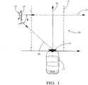
- a motor vehicle 11 and a radar sensor system 13 mounted to a front section of the motor vehicle 11.
- the radar sensor system 13 is preferably based on a millimeter wave radar sensor.
- a single channel radar sensor may be provided to minimize the production costs, while a multiple channel radar sensor may be provided to enhance the detection performance.
- the radar sensor system 13 can be connected to an electronic processing device (not shown), for example an advanced emergency braking system, a pedestrian collision avoidance system or an autonomous driving system. While a central mounting of the radar sensor system 13 is shown, a mounting to a corner section, a side section or a rear section of the motor vehicle 11 could equally be provided.
- the motor vehicle 11 is moving in a driving direction 15 on a lane 17.
- An object 19 in the form of a pedestrian crossing the lane 17 is present in the traffic space 23 in front of the motor vehicle 11.
- the object 19 is moving in a moving direction 21.
- Other examples of objects to be observed by the radar sensor system 13 are cyclists and vehicles.
- the radar sensor system 13 is configured for transmitting a primary radar signal into the traffic space 23 and for detecting objects 19 present in the traffic space 23 on the basis of a secondary radar signal reflected by the objects 19.
- the line 25 which extends from the object 19 to the active region of the radar sensor system 13 is called "line of sight".
- the observed bulk speed v ob of the object 19, i. e. the speed component related to the main body 27 of the object 19 and oriented along the line of sight 25, can be determined in a known manner using the Doppler effect.
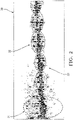
- FIG. 2 An exemplary Micro-Doppler spectrogram 30 of a moving cyclist is shown in Fig. 2 .
- the horizontal axis is a time axis, whereas the vertical axis is a Doppler shift axis or a radial velocity axis.
- the generation of the Micro-Doppler spectrogram 30 can be carried out by means of a Short-Time-Fourier-Transform (STFT) or a Wigner-Ville-Distribution technique (WVD technique).
- STFT Short-Time-Fourier-Transform
- WVD technique Wigner-Ville-Distribution technique
- a Micro-Doppler spectrogram of a pedestrian, a motor vehicle or a helicopter includes similar Micro-Doppler patterns that correspond to a gait cycle of the pedestrian, a wheel rotation of the motor vehicle or a rotor blade movement of the helicopter, respectively.
- the Micro-Doppler patterns 31, 32 caused by these motions are at least essentially periodic.
- the periodicity quantity can be an average cycle duration, an average repetition frequency or a number of time bins related to one period or cycle of the corresponding pattern. In case of a pedestrian, the periodicity quantity is characteristic for the pedestrian's gait cycle.
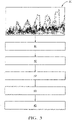
- a periodicity quantity relating to an at least essentially periodic motion of a part of the object 19 is determined on the basis of a Micro-Doppler spectrogram analysis by means of the electronic processing device, as is explained in greater detail below.
- a Micro-Doppler spectrogram 30 is generated as an input for the subsequent steps.
- a step 41 the course of a periodic signal component corresponding to a Micro-Doppler pattern 31, 32 is determined.
- a spread measure of the signal component is estimated.
- a smoothed curve is fitted to the periodic signal component by means of an adaptive curve-fitting process.
- the positions of the peaks and/or valleys of the smoothed curve are determined.
- a periodicity quantity is determined based on the determined positions of the peaks and valleys.
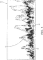
- Fig. 4 shows an exemplary Micro-Doppler spectrogram 30' of a pedestrian in an enlarged view.
- Three curves corresponding to the courses of different motion components are shown in the Micro-Doppler spectrogram 30'.
- the course 50 of the observed bulk speed v ob is shown as a solid black line
- the upper envelope 51 of the Micro-Doppler spectrogram 30' and the lower envelope 52 of the Micro-Doppler spectrogram 30' are shown as dashed lines.
- the cumulative amplitude distribution function is determined for each time slice.
- the course 50 of the observed bulk speed v ob is assigned to a percentile of about 50% of the cumulative amplitude distribution function.
- the upper envelope 51 is assigned to a percentile of about 95% of the cumulative amplitude distribution function, whereas the lower envelope 52 is assigned to a percentile of about 5% of the cumulative amplitude distribution function.
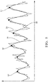
- FIG. 5 An exemplary course 54 of E diff over time is shown in Fig. 5 .
- a smoothed curve 55 fitted to this course 54 in step 43 ( Fig. 3 ) is equally shown.
- the window size used in the adaptive curve-fitting process is adapted to the variation of the observed bulk speed v ob .
- a preferred value for L 0 cycle is 1.4 m, since the typical gait-cycle of a pedestrian is around 1.2 m - 1.6 m, whereas a preferred value for V 0 is 1.5 m/s.
- the adaptive curve fitting process in step 43 is carried out by means of a kernel function.
- a kernel function is selected that smooths the raw signal so as to remove high frequency components while simultaneously maintaining the peak magnitude levels.
- Preferred kernel functions are high-order least-square polynomial kernels and high-order Savitzky-Golay kernels. According to a specific embodiment, a 2 nd order or a 3 rd order kernel is selected.
- step 44 a peak finding process is performed to find the peaks 57 of the smoothed curve 55.
- peaks 57 are determined that satisfy the following conditions:
- the valleys 58 of the smoothed curve 55 can be found in an analogous manner.
- T n cycle N n cycle ⁇ ⁇ t
- the period T n cycle and the repetition frequency f n cycle of the corresponding Micro-Doppler pattern 31, 32 can be determined.
- the duration between two consecutive peaks 57 or valleys 58 is the duration of one footstep cycle.
- a gait-cycle includes two footsteps.
- a recursive state estimator in particular a Kalman filter
- the random variables w n-1 and q n represent the process noise and the measurement noise.
- the subscripts n , n-1 indicate the current state and the previous state, respectively.
- the dot refers to the derivative of V.
- the peaks 57 found in the peak finding process can be used for a segmentation process, wherein the starting point and the ending point of the corresponding Micro-Doppler pattern 31, 32 are determined.
- the first peak 57 of a sequence of peaks 57 can be defined as a starting position of a segment, whereas the last peak 57 of a sequence of peaks 57 is defined as an ending position of a segment.
- the invention enables a reliable recognition of moving objects 19 by means of a radar sensor system 13 even in case the available observation time is rather short.
Claims (12)
- Procédé pour la reconnaissance d'un objet (19) au moyen d'un système de capteur radar (13), dans lequelun signal radar primaire est émis dans un espace d'observation (23),un signal radar secondaire réfléchi par l'objet (19) est reçu,un spectrogramme micro-Doppler (30, 30') du signal radar secondaire est généré et au moins une quantité de périodicité se rapportant à un mouvement au moins essentiellement périodique d'une partie de l'objet (19) est déterminée sur la base du spectrogramme micro-Doppler (30, 30'),dans lequel la détermination de ladite au moins une quantité de périodicité inclut les étapes consistant à :(i) déterminer l'évolution dans le temps d'au moins une composante de signal périodique (50, 51, 52, 54) correspondant à un motif au moins essentiellement périodique (31, 32) du spectrogramme micro-Doppler (30, 30'),(ii) ajuster une courbe lissée (55) à ladite au moins une composante de signal périodique (50, 51, 52, 54),(iii) déterminer les positions d'une pluralité de pics (57) et/ou de vallées (58) de la courbe lissée (55) et(iv) déterminer la quantité de périodicité sur la base des positions déterminées des pics (57) et/ou des vallées (58),caractérisé en ce que,à l'étape (i), les évolutions dans le temps d'une enveloppe supérieure (51), d'une enveloppe inférieure (52) et d'une différence (54) entre une enveloppe supérieure (51) et une enveloppe inférieure (52) du spectrogramme micro-Doppler (30, 30') sont déterminées sous la forme d'évolutions dans le temps de composantes de signaux périodiques.
- Procédé selon la revendication 1,
caractérisé en ce que,
à l'étape (ii), la courbe lissée (55) est ajustée à la composante de signal périodique (50, 51, 52, 54) au moyen d'un traitement d'ajustement de courbe adaptatif. - Procédé selon la revendication 2,
caractérisé en ce
qu'au moins un paramètre de traitement du traitement d'ajustement de courbe adaptatif est adapté en continu pendant le traitement d'ajustement de courbe. - Procédé selon la revendication 3,
caractérisé en ce que
le paramètre de traitement est adapté sur la base d'une variation de vitesse déterminée de l'objet (19). - Procédé selon l'une quelconque des revendications précédentes,
caractérisé en ce que,
à l'étape (ii), l'ajustement de la courbe lissée (55) à la composante de signal périodique (50, 51, 52, 54) est effectué à l'aide d'une fonction fenêtre, en particulier à l'aide d'un noyau triangulaire, d'un noyau polynomial ou d'un noyau de Savitzky-Golay. - Procédé selon la revendication 5,
caractérisé en ce que
la taille de fenêtre de la fonction fenêtre est adaptée en continu pendant l'ajustement de la courbe lissée (55) à la composante de signal périodique (50, 51, 52, 54). - Procédé selon l'une quelconque des revendications précédentes,
caractérisé en ce que
le spectrogramme micro-Doppler (30, 30') est généré au moyen d'une analyse temps-fréquence, en particulier au moyen d'une transformée de Fourier à temps court (STFT) ou d'une technique de distribution de Wigner-Ville (technique WVD). - Procédé selon l'une quelconque des revendications précédentes,
caractérisé en ce que
l'étape (iii) inclut un traitement de segmentation, dans lequel le premier pic (57) d'une séquence de pics (57) est défini comme une position de début d'un segment et/ou le dernier pic (57) d'une séquence de pics (57) est défini comme une position de fin d'un segment. - Procédé selon l'une quelconque des revendications précédentes,
caractérisé en ce que,
à l'étape (iv), la quantité de périodicité est estimée au moyen d'un estimateur d'état récursif, en particulier d'un filtre de Kalman. - Système pour la reconnaissance d'un objet (19) comprenant :un système de capteur radar (13) pour émettre un signal radar primaire dans un espace d'observation (23) et pour recevoir un signal radar secondaire réfléchi par l'objet (19) etun dispositif de traitement électronique pour traiter le signal radar secondaire,caractérisé en ce quele dispositif de traitement électronique est configuré pour mettre en œuvre un procédé selon l'une quelconque des revendications précédentes.
- Système selon la revendication 10,
caractérisé en ce que
le système de capteur radar (13) est configuré pour être monté sur ou dans un véhicule automobile (11). - Produit programme d'ordinateur incluant un code de programme exécutable qui, lorsqu'il est exécuté, amène un système selon la revendication 10 ou 11 à mettre en œuvre un procédé selon l'une quelconque des revendications 1 à 9.
Priority Applications (3)
| Application Number | Priority Date | Filing Date | Title |
|---|---|---|---|
| EP18166530.8A EP3553551B1 (fr) | 2018-04-10 | 2018-04-10 | Procédé de reconnaissance d'un objet |
| US16/359,301 US11131766B2 (en) | 2018-04-10 | 2019-03-20 | Method for the recognition of an object |
| CN201910270276.4A CN110361736B (zh) | 2018-04-10 | 2019-04-04 | 识别物体的方法 |
Applications Claiming Priority (1)
| Application Number | Priority Date | Filing Date | Title |
|---|---|---|---|
| EP18166530.8A EP3553551B1 (fr) | 2018-04-10 | 2018-04-10 | Procédé de reconnaissance d'un objet |
Publications (2)
| Publication Number | Publication Date |
|---|---|
| EP3553551A1 EP3553551A1 (fr) | 2019-10-16 |
| EP3553551B1 true EP3553551B1 (fr) | 2022-06-01 |
Family
ID=61965770
Family Applications (1)
| Application Number | Title | Priority Date | Filing Date |
|---|---|---|---|
| EP18166530.8A Active EP3553551B1 (fr) | 2018-04-10 | 2018-04-10 | Procédé de reconnaissance d'un objet |
Country Status (3)
| Country | Link |
|---|---|
| US (1) | US11131766B2 (fr) |
| EP (1) | EP3553551B1 (fr) |
| CN (1) | CN110361736B (fr) |
Families Citing this family (13)
| Publication number | Priority date | Publication date | Assignee | Title |
|---|---|---|---|---|
| EP3553552B1 (fr) * | 2018-04-11 | 2022-05-25 | Aptiv Technologies Limited | Procédé de reconnaissance d'un piéton en mouvement |
| EP3553559B1 (fr) | 2018-04-11 | 2022-06-01 | Aptiv Technologies Limited | Procédé de reconnaissance d'objets |
| TWI734252B (zh) * | 2019-11-08 | 2021-07-21 | 立積電子股份有限公司 | 雷達及雷達回波訊號的背景成分更新方法 |
| DE102019220526A1 (de) * | 2019-12-23 | 2021-06-24 | Robert Bosch Gesellschaft mit beschränkter Haftung | Verfahren und Vorrichtung zum Bestimmen von mindestens einem Knickwinkel eines Fahrzeuggespanns |
| CN111803045A (zh) * | 2020-01-17 | 2020-10-23 | 南京邮电大学 | 一种基于lfmcw毫米波的生命体征检测系统 |
| CN113341405B (zh) * | 2020-02-18 | 2023-10-13 | 南京大学 | 一种消除近距离处车轮微多普勒影响的雷达跟踪方法 |
| DE102020206639B4 (de) | 2020-05-27 | 2022-12-01 | Robert Bosch Gesellschaft mit beschränkter Haftung | Erkennung und/oder Ortung von Objekten anhand von Radardaten |
| TWI756728B (zh) * | 2020-07-01 | 2022-03-01 | 立積電子股份有限公司 | 物體辨識方法及物體辨識裝置 |
| CN111830483B (zh) * | 2020-09-16 | 2020-12-22 | 福瑞泰克智能系统有限公司 | 一种具有微动效应的目标的确定方法、装置、电子设备及存储介质 |
| CN112462342B (zh) * | 2020-11-06 | 2021-11-02 | 中国人民解放军空军预警学院雷达士官学校 | 一种高机动弱目标的阶段离散化维格纳霍夫变换时频形态自重构检测方法 |
| CN113344033B (zh) * | 2021-05-17 | 2022-05-17 | 电子科技大学 | 一种旋翼无人机与飞鸟目标分类中的判别特征提取方法 |
| CN114002658B (zh) * | 2021-12-28 | 2022-05-24 | 中南大学 | 基于点迹曲线关联曲线分离的雷达目标微动特征提取方法 |
| WO2023220912A1 (fr) * | 2022-05-17 | 2023-11-23 | Qualcomm Incorporated | Identification de cible au moyen d'une signature micro-doppler |
Family Cites Families (43)
| Publication number | Priority date | Publication date | Assignee | Title |
|---|---|---|---|---|
| DE2514868C3 (de) * | 1975-04-04 | 1979-05-17 | Standard Elektrik Lorenz Ag, 7000 Stuttgart | FM-Schwebungs-Rückstrahlortungsgerät zur gleichzeitigen Entfernungs- und Geschwindigkeitsmessung |
| FR2413668A1 (fr) * | 1978-01-03 | 1979-07-27 | Thomson Csf | Radar a correlation assurant une detection proche a basse altitude et systeme comportant un tel radar |
| FR2571150B1 (fr) * | 1984-09-28 | 1986-11-21 | Thomson Csf | Circuit d'elimination d'echos de mobiles lents pour radar doppler |
| US4958638A (en) * | 1988-06-30 | 1990-09-25 | Georgia Tech Research Corporation | Non-contact vital signs monitor |
| US5689286A (en) | 1995-05-23 | 1997-11-18 | Ast Research, Inc. | Component-based icon construction and customization system |
| US5689268A (en) * | 1996-08-02 | 1997-11-18 | Boeing North American, Inc. | Radar detection and classification of helicopters |
| US6653971B1 (en) * | 1999-05-14 | 2003-11-25 | David L. Guice | Airborne biota monitoring and control system |
| US6121916A (en) | 1999-07-16 | 2000-09-19 | Eaton-Vorad Technologies, L.L.C. | Method and apparatus for recognizing stationary objects with a moving side-looking radar |
| US20020028003A1 (en) | 2000-03-27 | 2002-03-07 | Krebs David E. | Methods and systems for distinguishing individuals utilizing anatomy and gait parameters |
| US7016782B2 (en) | 2002-05-30 | 2006-03-21 | Delphi Technologies, Inc. | Collision detection system and method of estimating miss distance |
| US6674394B1 (en) | 2003-03-28 | 2004-01-06 | Visteon Global Technologies, Inc. | Method for determining object location from side-looking sensor data |
| US7647049B2 (en) * | 2006-07-12 | 2010-01-12 | Telefonaktiebolaget L M Ericsson (Publ) | Detection of high velocity movement in a telecommunication system |
| US20100074379A1 (en) * | 2008-04-01 | 2010-03-25 | Ming-Chiang Li | Tuning replica generation methods and apparatus for their most optimum performance in processing transient signals |
| US20100286543A1 (en) * | 2009-05-05 | 2010-11-11 | Siemens Medical Solutions Usa, Inc. | Automated Cardiac Status Determination System |
| US8529458B2 (en) * | 2009-09-28 | 2013-09-10 | State Of Oregon By And Through The State Board Of Higher Education On Behalf Of Portland State University | Method and apparatus for assessment of fluid responsiveness |
| GB2488699B (en) * | 2009-11-03 | 2014-09-17 | Vawd Applied Science & Technology Corp | Standoff range sense through obstruction radar system |
| JP5423891B2 (ja) | 2010-06-16 | 2014-02-19 | トヨタ自動車株式会社 | 対象物識別装置、及びその方法 |
| DE102010062235A1 (de) | 2010-12-01 | 2012-06-06 | Robert Bosch Gmbh | Fahrerassistenzsystem zur Detektion eines Objekts in einer Fahrzeugumgebung |
| EP2589979A1 (fr) | 2011-11-03 | 2013-05-08 | Thales Nederland B.V. | Système de caractérisation de mouvement d'un individu, notamment un individu humain |
| US20200064444A1 (en) | 2015-07-17 | 2020-02-27 | Origin Wireless, Inc. | Method, apparatus, and system for human identification based on human radio biometric information |
| CN103529436A (zh) * | 2013-10-12 | 2014-01-22 | 南京信息工程大学 | 基于hht的无接触生命探测中呼吸和心跳信号的分离及时频分析方法 |
| US10721384B2 (en) * | 2014-03-27 | 2020-07-21 | Sony Corporation | Camera with radar system |
| US10809365B2 (en) * | 2014-08-25 | 2020-10-20 | Texas Instruments Incorporated | Vibration parameters monitoring using FMCW radar |
| US10185030B2 (en) | 2014-09-05 | 2019-01-22 | GM Global Technology Operations LLC | Object boundary detection for automotive radar imaging |
| DE102014218092A1 (de) | 2014-09-10 | 2016-03-10 | Volkswagen Aktiengesellschaft | Erstellen eines Abbilds der Umgebung eines Kraftfahrzeugs und Bestimmen der relativen Geschwindigkeit zwischen dem Kraftfahrzeug und Objekten in der Umgebung |
| CN104360336B (zh) * | 2014-11-24 | 2017-02-08 | 电子科技大学 | 一种自适应提取雷达目标微动周期的新方法 |
| US10481696B2 (en) * | 2015-03-03 | 2019-11-19 | Nvidia Corporation | Radar based user interface |
| CN111522434A (zh) * | 2015-04-30 | 2020-08-11 | 谷歌有限责任公司 | 用于手势跟踪和识别的基于rf的微运动跟踪 |
| DE102015007040B4 (de) * | 2015-05-30 | 2020-09-24 | Audi Ag | Verfahren zur Detektion und Klassifikation von Fußgängern in einer Umgebung eines Kraftfahrzeugs und Kraftfahrzeug |
| US9604639B2 (en) * | 2015-08-28 | 2017-03-28 | Delphi Technologies, Inc. | Pedestrian-intent-detection for automated vehicles |
| US10054672B2 (en) | 2015-08-31 | 2018-08-21 | Veoneer Us, Inc. | Apparatus and method for detecting and correcting for blockage of an automotive radar sensor |
| US10817065B1 (en) * | 2015-10-06 | 2020-10-27 | Google Llc | Gesture recognition using multiple antenna |
| US10571562B2 (en) * | 2016-03-25 | 2020-02-25 | Magna Electronics Inc. | Vehicle short range sensing system using RF sensors |
| EP3459050A4 (fr) * | 2016-05-18 | 2020-04-01 | Auckland Uniservices Limited | Procédé d'enregistrement d'images |
| JP2017223461A (ja) | 2016-06-13 | 2017-12-21 | パナソニックIpマネジメント株式会社 | レーダ装置および検出方法 |
| DE102016213007A1 (de) * | 2016-07-15 | 2018-01-18 | Robert Bosch Gmbh | Verfahren und System zur Abtastung eines Objekts |
| DE102016213254B3 (de) * | 2016-07-20 | 2017-07-13 | Volkswagen Aktiengesellschaft | Verfahren zum Erfassen einer Objektbewegung eines Objekts in einer Umgebung eines Kraftfahrzeugs, Steuervorrichtung und Kraftfahrzeugs |
| DE102016215102A1 (de) * | 2016-08-12 | 2017-12-07 | Conti Temic Microelectronic Gmbh | Fußgängererkennung mittels Radar |
| CN106483514B (zh) * | 2016-09-23 | 2020-01-14 | 电子科技大学 | 一种基于eemd和支持向量机的飞机运动模式识别方法 |
| US11467278B2 (en) * | 2017-06-29 | 2022-10-11 | Sensing Management Pty Limited | System and method of detecting objects |
| US11295119B2 (en) | 2017-06-30 | 2022-04-05 | The Johns Hopkins University | Systems and method for action recognition using micro-doppler signatures and recurrent neural networks |
| DE102017211432A1 (de) * | 2017-07-05 | 2019-01-10 | Robert Bosch Gmbh | System zum Detektieren eines bewegten Objekts |
| EP3553552B1 (fr) | 2018-04-11 | 2022-05-25 | Aptiv Technologies Limited | Procédé de reconnaissance d'un piéton en mouvement |
-
2018
- 2018-04-10 EP EP18166530.8A patent/EP3553551B1/fr active Active
-
2019
- 2019-03-20 US US16/359,301 patent/US11131766B2/en active Active
- 2019-04-04 CN CN201910270276.4A patent/CN110361736B/zh active Active
Also Published As
| Publication number | Publication date |
|---|---|
| CN110361736A (zh) | 2019-10-22 |
| US20190310362A1 (en) | 2019-10-10 |
| US11131766B2 (en) | 2021-09-28 |
| CN110361736B (zh) | 2023-06-06 |
| EP3553551A1 (fr) | 2019-10-16 |
Similar Documents
| Publication | Publication Date | Title |
|---|---|---|
| EP3553551B1 (fr) | Procédé de reconnaissance d'un objet | |
| EP3553552B1 (fr) | Procédé de reconnaissance d'un piéton en mouvement | |
| JP7394582B2 (ja) | レーダーデータを処理する装置及び方法 | |
| CN107076836B (zh) | 用于对机动车辆周围区域中的对象分类的方法、驾驶员辅助系统和机动车辆 | |
| EP2998761B1 (fr) | Système radar à détection multicible basé sur la phase | |
| US10139833B1 (en) | Six-dimensional point cloud system for a vehicle | |
| US20040189512A1 (en) | Collision prediction device, method of predicting collision, and computer product | |
| CN107103275B (zh) | 使用雷达和视觉基于车轮进行的车辆检测和追踪 | |
| CN110431436B (zh) | 求取至少一个目标的径向相对加速度的方法和雷达设备 | |
| KR102490991B1 (ko) | 움직이는 물체를 검출하기 위한 시스템 | |
| JP7173735B2 (ja) | レーダ装置及び信号処理方法 | |
| JP6993136B2 (ja) | レーダ装置および物標検知方法 | |
| KR20190050238A (ko) | 긴급 제동 시스템 및 그 제어방법 | |
| KR20200108464A (ko) | 임계적인 횡방향 이동을 검출하는 방법 및 장치 | |
| CN105015469A (zh) | 物体检测装置以及物体检测方法 | |
| US20050004719A1 (en) | Device and method for determining the position of objects in the surroundings of a motor vehicle | |
| CN110678776B (zh) | 用于增强的对象跟踪的系统 | |
| EP4075159A1 (fr) | Système radar utilisant un modèle appris par machine pour la détection d'objets fixes | |
| JP2001141812A (ja) | Fm−cwレーダ装置 | |
| JP7167871B2 (ja) | 物標検出装置 | |
| CN110691985B (zh) | 用于增强的对象追踪的系统 | |
| CN110832340B (zh) | 用于探测运动对象的系统 | |
| CN114089328A (zh) | 确定行人移动速度的方法及行人定位方法、车载雷达 | |
| CN117716258A (zh) | 车辆用雷达装置 | |
| KR20180064127A (ko) | 타켓 물체 감지 방법 및 그 장치 |
Legal Events
| Date | Code | Title | Description |
|---|---|---|---|
| PUAI | Public reference made under article 153(3) epc to a published international application that has entered the european phase |
Free format text: ORIGINAL CODE: 0009012 |
|
| STAA | Information on the status of an ep patent application or granted ep patent |
Free format text: STATUS: THE APPLICATION HAS BEEN PUBLISHED |
|
| AK | Designated contracting states |
Kind code of ref document: A1 Designated state(s): AL AT BE BG CH CY CZ DE DK EE ES FI FR GB GR HR HU IE IS IT LI LT LU LV MC MK MT NL NO PL PT RO RS SE SI SK SM TR |
|
| AX | Request for extension of the european patent |
Extension state: BA ME |
|
| STAA | Information on the status of an ep patent application or granted ep patent |
Free format text: STATUS: REQUEST FOR EXAMINATION WAS MADE |
|
| 17P | Request for examination filed |
Effective date: 20200319 |
|
| RBV | Designated contracting states (corrected) |
Designated state(s): AL AT BE BG CH CY CZ DE DK EE ES FI FR GB GR HR HU IE IS IT LI LT LU LV MC MK MT NL NO PL PT RO RS SE SI SK SM TR |
|
| RIC1 | Information provided on ipc code assigned before grant |
Ipc: G01S 13/90 20060101ALI20211104BHEP Ipc: G01S 13/931 20200101ALI20211104BHEP Ipc: G01S 13/58 20060101ALI20211104BHEP Ipc: G01S 7/41 20060101AFI20211104BHEP |
|
| GRAP | Despatch of communication of intention to grant a patent |
Free format text: ORIGINAL CODE: EPIDOSNIGR1 |
|
| STAA | Information on the status of an ep patent application or granted ep patent |
Free format text: STATUS: GRANT OF PATENT IS INTENDED |
|
| INTG | Intention to grant announced |
Effective date: 20211210 |
|
| GRAS | Grant fee paid |
Free format text: ORIGINAL CODE: EPIDOSNIGR3 |
|
| GRAA | (expected) grant |
Free format text: ORIGINAL CODE: 0009210 |
|
| STAA | Information on the status of an ep patent application or granted ep patent |
Free format text: STATUS: THE PATENT HAS BEEN GRANTED |
|
| AK | Designated contracting states |
Kind code of ref document: B1 Designated state(s): AL AT BE BG CH CY CZ DE DK EE ES FI FR GB GR HR HU IE IS IT LI LT LU LV MC MK MT NL NO PL PT RO RS SE SI SK SM TR |
|
| REG | Reference to a national code |
Ref country code: GB Ref legal event code: FG4D |
|
| REG | Reference to a national code |
Ref country code: AT Ref legal event code: REF Ref document number: 1495760 Country of ref document: AT Kind code of ref document: T Effective date: 20220615 Ref country code: CH Ref legal event code: EP Ref country code: DE Ref legal event code: R096 Ref document number: 602018036097 Country of ref document: DE |
|
| REG | Reference to a national code |
Ref country code: IE Ref legal event code: FG4D |
|
| REG | Reference to a national code |
Ref country code: LT Ref legal event code: MG9D |
|
| REG | Reference to a national code |
Ref country code: NL Ref legal event code: MP Effective date: 20220601 |
|
| PG25 | Lapsed in a contracting state [announced via postgrant information from national office to epo] |
Ref country code: SE Free format text: LAPSE BECAUSE OF FAILURE TO SUBMIT A TRANSLATION OF THE DESCRIPTION OR TO PAY THE FEE WITHIN THE PRESCRIBED TIME-LIMIT Effective date: 20220601 Ref country code: NO Free format text: LAPSE BECAUSE OF FAILURE TO SUBMIT A TRANSLATION OF THE DESCRIPTION OR TO PAY THE FEE WITHIN THE PRESCRIBED TIME-LIMIT Effective date: 20220901 Ref country code: LT Free format text: LAPSE BECAUSE OF FAILURE TO SUBMIT A TRANSLATION OF THE DESCRIPTION OR TO PAY THE FEE WITHIN THE PRESCRIBED TIME-LIMIT Effective date: 20220601 Ref country code: HR Free format text: LAPSE BECAUSE OF FAILURE TO SUBMIT A TRANSLATION OF THE DESCRIPTION OR TO PAY THE FEE WITHIN THE PRESCRIBED TIME-LIMIT Effective date: 20220601 Ref country code: GR Free format text: LAPSE BECAUSE OF FAILURE TO SUBMIT A TRANSLATION OF THE DESCRIPTION OR TO PAY THE FEE WITHIN THE PRESCRIBED TIME-LIMIT Effective date: 20220902 Ref country code: FI Free format text: LAPSE BECAUSE OF FAILURE TO SUBMIT A TRANSLATION OF THE DESCRIPTION OR TO PAY THE FEE WITHIN THE PRESCRIBED TIME-LIMIT Effective date: 20220601 Ref country code: ES Free format text: LAPSE BECAUSE OF FAILURE TO SUBMIT A TRANSLATION OF THE DESCRIPTION OR TO PAY THE FEE WITHIN THE PRESCRIBED TIME-LIMIT Effective date: 20220601 Ref country code: BG Free format text: LAPSE BECAUSE OF FAILURE TO SUBMIT A TRANSLATION OF THE DESCRIPTION OR TO PAY THE FEE WITHIN THE PRESCRIBED TIME-LIMIT Effective date: 20220901 |
|
| REG | Reference to a national code |
Ref country code: AT Ref legal event code: MK05 Ref document number: 1495760 Country of ref document: AT Kind code of ref document: T Effective date: 20220601 |
|
| PG25 | Lapsed in a contracting state [announced via postgrant information from national office to epo] |
Ref country code: RS Free format text: LAPSE BECAUSE OF FAILURE TO SUBMIT A TRANSLATION OF THE DESCRIPTION OR TO PAY THE FEE WITHIN THE PRESCRIBED TIME-LIMIT Effective date: 20220601 Ref country code: PL Free format text: LAPSE BECAUSE OF FAILURE TO SUBMIT A TRANSLATION OF THE DESCRIPTION OR TO PAY THE FEE WITHIN THE PRESCRIBED TIME-LIMIT Effective date: 20220601 Ref country code: LV Free format text: LAPSE BECAUSE OF FAILURE TO SUBMIT A TRANSLATION OF THE DESCRIPTION OR TO PAY THE FEE WITHIN THE PRESCRIBED TIME-LIMIT Effective date: 20220601 |
|
| PG25 | Lapsed in a contracting state [announced via postgrant information from national office to epo] |
Ref country code: NL Free format text: LAPSE BECAUSE OF FAILURE TO SUBMIT A TRANSLATION OF THE DESCRIPTION OR TO PAY THE FEE WITHIN THE PRESCRIBED TIME-LIMIT Effective date: 20220601 |
|
| PG25 | Lapsed in a contracting state [announced via postgrant information from national office to epo] |
Ref country code: SM Free format text: LAPSE BECAUSE OF FAILURE TO SUBMIT A TRANSLATION OF THE DESCRIPTION OR TO PAY THE FEE WITHIN THE PRESCRIBED TIME-LIMIT Effective date: 20220601 Ref country code: SK Free format text: LAPSE BECAUSE OF FAILURE TO SUBMIT A TRANSLATION OF THE DESCRIPTION OR TO PAY THE FEE WITHIN THE PRESCRIBED TIME-LIMIT Effective date: 20220601 Ref country code: RO Free format text: LAPSE BECAUSE OF FAILURE TO SUBMIT A TRANSLATION OF THE DESCRIPTION OR TO PAY THE FEE WITHIN THE PRESCRIBED TIME-LIMIT Effective date: 20220601 Ref country code: PT Free format text: LAPSE BECAUSE OF FAILURE TO SUBMIT A TRANSLATION OF THE DESCRIPTION OR TO PAY THE FEE WITHIN THE PRESCRIBED TIME-LIMIT Effective date: 20221003 Ref country code: EE Free format text: LAPSE BECAUSE OF FAILURE TO SUBMIT A TRANSLATION OF THE DESCRIPTION OR TO PAY THE FEE WITHIN THE PRESCRIBED TIME-LIMIT Effective date: 20220601 Ref country code: CZ Free format text: LAPSE BECAUSE OF FAILURE TO SUBMIT A TRANSLATION OF THE DESCRIPTION OR TO PAY THE FEE WITHIN THE PRESCRIBED TIME-LIMIT Effective date: 20220601 Ref country code: AT Free format text: LAPSE BECAUSE OF FAILURE TO SUBMIT A TRANSLATION OF THE DESCRIPTION OR TO PAY THE FEE WITHIN THE PRESCRIBED TIME-LIMIT Effective date: 20220601 |
|
| PG25 | Lapsed in a contracting state [announced via postgrant information from national office to epo] |
Ref country code: IS Free format text: LAPSE BECAUSE OF FAILURE TO SUBMIT A TRANSLATION OF THE DESCRIPTION OR TO PAY THE FEE WITHIN THE PRESCRIBED TIME-LIMIT Effective date: 20221001 |
|
| REG | Reference to a national code |
Ref country code: DE Ref legal event code: R097 Ref document number: 602018036097 Country of ref document: DE |
|
| RAP4 | Party data changed (patent owner data changed or rights of a patent transferred) |
Owner name: APTIV TECHNOLOGIES LIMITED |
|
| PG25 | Lapsed in a contracting state [announced via postgrant information from national office to epo] |
Ref country code: AL Free format text: LAPSE BECAUSE OF FAILURE TO SUBMIT A TRANSLATION OF THE DESCRIPTION OR TO PAY THE FEE WITHIN THE PRESCRIBED TIME-LIMIT Effective date: 20220601 |
|
| PLBE | No opposition filed within time limit |
Free format text: ORIGINAL CODE: 0009261 |
|
| STAA | Information on the status of an ep patent application or granted ep patent |
Free format text: STATUS: NO OPPOSITION FILED WITHIN TIME LIMIT |
|
| PG25 | Lapsed in a contracting state [announced via postgrant information from national office to epo] |
Ref country code: DK Free format text: LAPSE BECAUSE OF FAILURE TO SUBMIT A TRANSLATION OF THE DESCRIPTION OR TO PAY THE FEE WITHIN THE PRESCRIBED TIME-LIMIT Effective date: 20220601 |
|
| 26N | No opposition filed |
Effective date: 20230302 |
|
| PG25 | Lapsed in a contracting state [announced via postgrant information from national office to epo] |
Ref country code: SI Free format text: LAPSE BECAUSE OF FAILURE TO SUBMIT A TRANSLATION OF THE DESCRIPTION OR TO PAY THE FEE WITHIN THE PRESCRIBED TIME-LIMIT Effective date: 20220601 |
|
| P01 | Opt-out of the competence of the unified patent court (upc) registered |
Effective date: 20230424 |
|
| PGFP | Annual fee paid to national office [announced via postgrant information from national office to epo] |
Ref country code: FR Payment date: 20230428 Year of fee payment: 6 Ref country code: DE Payment date: 20230426 Year of fee payment: 6 |
|
| PGFP | Annual fee paid to national office [announced via postgrant information from national office to epo] |
Ref country code: GB Payment date: 20230419 Year of fee payment: 6 |
|
| REG | Reference to a national code |
Ref country code: CH Ref legal event code: PL |
|
| PG25 | Lapsed in a contracting state [announced via postgrant information from national office to epo] |
Ref country code: LU Free format text: LAPSE BECAUSE OF NON-PAYMENT OF DUE FEES Effective date: 20230410 |
|
| REG | Reference to a national code |
Ref country code: BE Ref legal event code: MM Effective date: 20230430 |
|
| PG25 | Lapsed in a contracting state [announced via postgrant information from national office to epo] |
Ref country code: MC Free format text: LAPSE BECAUSE OF FAILURE TO SUBMIT A TRANSLATION OF THE DESCRIPTION OR TO PAY THE FEE WITHIN THE PRESCRIBED TIME-LIMIT Effective date: 20220601 |
|
| PG25 | Lapsed in a contracting state [announced via postgrant information from national office to epo] |
Ref country code: MC Free format text: LAPSE BECAUSE OF FAILURE TO SUBMIT A TRANSLATION OF THE DESCRIPTION OR TO PAY THE FEE WITHIN THE PRESCRIBED TIME-LIMIT Effective date: 20220601 Ref country code: LI Free format text: LAPSE BECAUSE OF NON-PAYMENT OF DUE FEES Effective date: 20230430 Ref country code: IT Free format text: LAPSE BECAUSE OF FAILURE TO SUBMIT A TRANSLATION OF THE DESCRIPTION OR TO PAY THE FEE WITHIN THE PRESCRIBED TIME-LIMIT Effective date: 20220601 Ref country code: CH Free format text: LAPSE BECAUSE OF NON-PAYMENT OF DUE FEES Effective date: 20230430 |
|
| REG | Reference to a national code |
Ref country code: IE Ref legal event code: MM4A |
|
| PG25 | Lapsed in a contracting state [announced via postgrant information from national office to epo] |
Ref country code: BE Free format text: LAPSE BECAUSE OF NON-PAYMENT OF DUE FEES Effective date: 20230430 |
|
| PG25 | Lapsed in a contracting state [announced via postgrant information from national office to epo] |
Ref country code: IE Free format text: LAPSE BECAUSE OF NON-PAYMENT OF DUE FEES Effective date: 20230410 |
|
| PG25 | Lapsed in a contracting state [announced via postgrant information from national office to epo] |
Ref country code: IE Free format text: LAPSE BECAUSE OF NON-PAYMENT OF DUE FEES Effective date: 20230410 |