EP3553552B1 - Procédé de reconnaissance d'un piéton en mouvement - Google Patents
Procédé de reconnaissance d'un piéton en mouvement Download PDFInfo
- Publication number
- EP3553552B1 EP3553552B1 EP18166844.3A EP18166844A EP3553552B1 EP 3553552 B1 EP3553552 B1 EP 3553552B1 EP 18166844 A EP18166844 A EP 18166844A EP 3553552 B1 EP3553552 B1 EP 3553552B1
- Authority
- EP
- European Patent Office
- Prior art keywords
- pedestrian
- accordance
- moving
- determined
- gait cycle
- Prior art date
- Legal status (The legal status is an assumption and is not a legal conclusion. Google has not performed a legal analysis and makes no representation as to the accuracy of the status listed.)
- Active
Links
Images


Classifications
-
- G—PHYSICS
- G06—COMPUTING OR CALCULATING; COUNTING
- G06V—IMAGE OR VIDEO RECOGNITION OR UNDERSTANDING
- G06V40/00—Recognition of biometric, human-related or animal-related patterns in image or video data
- G06V40/20—Movements or behaviour, e.g. gesture recognition
- G06V40/23—Recognition of whole body movements, e.g. for sport training
- G06V40/25—Recognition of walking or running movements, e.g. gait recognition
-
- G—PHYSICS
- G01—MEASURING; TESTING
- G01S—RADIO DIRECTION-FINDING; RADIO NAVIGATION; DETERMINING DISTANCE OR VELOCITY BY USE OF RADIO WAVES; LOCATING OR PRESENCE-DETECTING BY USE OF THE REFLECTION OR RERADIATION OF RADIO WAVES; ANALOGOUS ARRANGEMENTS USING OTHER WAVES
- G01S13/00—Systems using the reflection or reradiation of radio waves, e.g. radar systems; Analogous systems using reflection or reradiation of waves whose nature or wavelength is irrelevant or unspecified
- G01S13/02—Systems using reflection of radio waves, e.g. primary radar systems; Analogous systems
- G01S13/06—Systems determining position data of a target
- G01S13/46—Indirect determination of position data
-
- G—PHYSICS
- G01—MEASURING; TESTING
- G01S—RADIO DIRECTION-FINDING; RADIO NAVIGATION; DETERMINING DISTANCE OR VELOCITY BY USE OF RADIO WAVES; LOCATING OR PRESENCE-DETECTING BY USE OF THE REFLECTION OR RERADIATION OF RADIO WAVES; ANALOGOUS ARRANGEMENTS USING OTHER WAVES
- G01S13/00—Systems using the reflection or reradiation of radio waves, e.g. radar systems; Analogous systems using reflection or reradiation of waves whose nature or wavelength is irrelevant or unspecified
- G01S13/02—Systems using reflection of radio waves, e.g. primary radar systems; Analogous systems
- G01S13/50—Systems of measurement based on relative movement of target
- G01S13/58—Velocity or trajectory determination systems; Sense-of-movement determination systems
- G01S13/589—Velocity or trajectory determination systems; Sense-of-movement determination systems measuring the velocity vector
-
- G—PHYSICS
- G01—MEASURING; TESTING
- G01S—RADIO DIRECTION-FINDING; RADIO NAVIGATION; DETERMINING DISTANCE OR VELOCITY BY USE OF RADIO WAVES; LOCATING OR PRESENCE-DETECTING BY USE OF THE REFLECTION OR RERADIATION OF RADIO WAVES; ANALOGOUS ARRANGEMENTS USING OTHER WAVES
- G01S13/00—Systems using the reflection or reradiation of radio waves, e.g. radar systems; Analogous systems using reflection or reradiation of waves whose nature or wavelength is irrelevant or unspecified
- G01S13/02—Systems using reflection of radio waves, e.g. primary radar systems; Analogous systems
- G01S13/50—Systems of measurement based on relative movement of target
- G01S13/58—Velocity or trajectory determination systems; Sense-of-movement determination systems
- G01S13/62—Sense-of-movement determination
-
- G—PHYSICS
- G01—MEASURING; TESTING
- G01S—RADIO DIRECTION-FINDING; RADIO NAVIGATION; DETERMINING DISTANCE OR VELOCITY BY USE OF RADIO WAVES; LOCATING OR PRESENCE-DETECTING BY USE OF THE REFLECTION OR RERADIATION OF RADIO WAVES; ANALOGOUS ARRANGEMENTS USING OTHER WAVES
- G01S13/00—Systems using the reflection or reradiation of radio waves, e.g. radar systems; Analogous systems using reflection or reradiation of waves whose nature or wavelength is irrelevant or unspecified
- G01S13/88—Radar or analogous systems specially adapted for specific applications
- G01S13/93—Radar or analogous systems specially adapted for specific applications for anti-collision purposes
- G01S13/931—Radar or analogous systems specially adapted for specific applications for anti-collision purposes of land vehicles
-
- G—PHYSICS
- G01—MEASURING; TESTING
- G01S—RADIO DIRECTION-FINDING; RADIO NAVIGATION; DETERMINING DISTANCE OR VELOCITY BY USE OF RADIO WAVES; LOCATING OR PRESENCE-DETECTING BY USE OF THE REFLECTION OR RERADIATION OF RADIO WAVES; ANALOGOUS ARRANGEMENTS USING OTHER WAVES
- G01S7/00—Details of systems according to groups G01S13/00, G01S15/00, G01S17/00
- G01S7/02—Details of systems according to groups G01S13/00, G01S15/00, G01S17/00 of systems according to group G01S13/00
- G01S7/41—Details of systems according to groups G01S13/00, G01S15/00, G01S17/00 of systems according to group G01S13/00 using analysis of echo signal for target characterisation; Target signature; Target cross-section
- G01S7/415—Identification of targets based on measurements of movement associated with the target
-
- G—PHYSICS
- G06—COMPUTING OR CALCULATING; COUNTING
- G06V—IMAGE OR VIDEO RECOGNITION OR UNDERSTANDING
- G06V40/00—Recognition of biometric, human-related or animal-related patterns in image or video data
- G06V40/10—Human or animal bodies, e.g. vehicle occupants or pedestrians; Body parts, e.g. hands
- G06V40/103—Static body considered as a whole, e.g. static pedestrian or occupant recognition
-
- G—PHYSICS
- G01—MEASURING; TESTING
- G01S—RADIO DIRECTION-FINDING; RADIO NAVIGATION; DETERMINING DISTANCE OR VELOCITY BY USE OF RADIO WAVES; LOCATING OR PRESENCE-DETECTING BY USE OF THE REFLECTION OR RERADIATION OF RADIO WAVES; ANALOGOUS ARRANGEMENTS USING OTHER WAVES
- G01S13/00—Systems using the reflection or reradiation of radio waves, e.g. radar systems; Analogous systems using reflection or reradiation of waves whose nature or wavelength is irrelevant or unspecified
- G01S13/88—Radar or analogous systems specially adapted for specific applications
- G01S13/93—Radar or analogous systems specially adapted for specific applications for anti-collision purposes
- G01S13/931—Radar or analogous systems specially adapted for specific applications for anti-collision purposes of land vehicles
- G01S2013/9327—Sensor installation details
- G01S2013/93271—Sensor installation details in the front of the vehicles
Definitions
- the present invention relates to a method for the recognition of a moving pedestrian by means of a radar sensor system, wherein a primary radar signal is transmitted into an observation space, and a secondary radar signal reflected by the moving pedestrian is received and processed.
- Radar sensor systems are used in a wide range of applications. For example, modern motor vehicles are often equipped with radar sensor systems to detect other vehicles, obstacles or vulnerable road users such as pedestrians or cyclists. A detection and classification of objects in a traffic space from a host vehicle is in particular needed for various advanced driver assistance systems (ADAS), such as advanced emergency braking (AEB) systems, collision avoidance systems and autonomous driving systems.
- ADAS advanced driver assistance systems
- AEB advanced emergency braking
- the known Doppler effect is used to gather information relating to moving objects.
- the Doppler effect or Doppler shift is a change in frequency observed when a wave source moves relative to the receiver. In case of a pedestrian crossing the street in front of a motor vehicle, the Doppler effect is the less distinct, the closer the pedestrian approaches the center of the lane. In practice, it is therefore difficult to correctly identify pedestrians crossing the lane.
- EP 1 367 411 A2 discloses a collision detection system including a sensor for measuring the range to an object as well as a range rate of the object and a controller for estimating a miss distance of the object as a function of the measured range and the range rate.
- DE 10 2010 062235 A1 discloses a method for detecting an object in the surrounding of a vehicle and for determining the direction to the object based on a Doppler shift.
- the processing of the secondary radar signal includes the steps:
- the Doppler frequency shift mainly results from the movement of the observed object as a whole, i.e. in case of an observed pedestrian from the movement of the pedestrian's torso. Beside this shift resulting from the main body movement, there usually are sidebands relating to moving parts of the object. For example, swinging arms or legs of a pedestrian can cause additional Doppler shifts. Such additional shifts are discernible in a Micro-Doppler spectrogram.
- Micro-Doppler spectrograms The generation of Micro-Doppler spectrograms is disclosed, for example, in the book of Chen V.C., "The Micro-Doppler Effect in Radar", Artech House, 2011 , or in the paper of Yan et al., “Micro-Doppler Based Classifying Features for Automotive Radar VRU Target Classification", 25th International Technical Conference on the Enhanced Safety of Vehicles (ESV), June 5-8, 2017, Detroit, Michigan, United States .
- Micro-Doppler-signature The superposition of Doppler shifts from each individual component is called a "Micro-Doppler-signature". Micro-Doppler-signatures can be analyzed to classify detected objects. The use of Doppler spectrograms for a discrimination of pedestrians is disclosed, for example, in the paper of Gürbüz S.Z. et al., "Detection and Identification of Human Targets in Radar Data", SPIE 6567, Signal Processing, Sensor Fusion and Target Recognition XVI, 656701, May 2007 .
- the illumination angle is an important quantity to be used in various processing and evaluation steps.
- the knowledge of the illumination angle enables a particularly reliable detection of crossing pedestrians.
- the speed of a pedestrian in the moving direction can be calculated if the illumination angle is known.
- the illumination angle can be estimated by means of an angle-finding process.
- Such a process requires a multiple channel radar system, which is rather costly.
- a method in accordance with the invention is not dependent on the presence of a multiple channel radar sensor and may be implemented directly in the range-Doppler domain. The invention thus enables the fabrication of low-cost pedestrian recognition systems.
- v the speed of the moving pedestrian in the moving direction
- v ob the observed bulk speed
- ⁇ the illumination angle
- the Micro-Doppler spectrogram may be generated by means of a time-frequency analysis, in particular by means of a Short-Time-Fourier-Transform (STFT) or a Wigner-Ville-Distribution technique (WVD technique).
- STFT Short-Time-Fourier-Transform
- WVD technique Wigner-Ville-Distribution technique
- the secondary radar signal or a signal derived from the secondary radar signal may be subjected to a time-frequency analysis.
- the observed bulk speed can be determined by means of a percentile-based method or a curve-fitting method. Specifically, it is possible to calculate the cumulative amplitude distribution for each time slice and to determine the observed bulk speed to correspond to a percentile of about 50% of the cumulative amplitude distribution function. According to an embodiment of the invention, a percentile-based method or a curve-fitting method as disclosed in the paper of Gürbüz S.Z. et al., "Operational assessment and adaptive selection of micro-Doppler features", IET Radar Sonar Navig., Vol. 9, Iss. 9, pp. 1196-1204, 2015 , may be used to determine the observed bulk speed.
- the at least one gait cycle parameter is an average duration of the pedestrian's gait cycle, an average gait cycle repetition frequency or a number of time bins related to one gait cycle.
- One gait cycle usually corresponds to two footsteps.
- the at least one gait cycle parameter is determined by means of a Fourier analysis.
- a Fourier analysis enables the extraction of periodic components related to specific movements of body parts from the Micro-Doppler spectrogram.
- a Fast Fourier Transform may be applied to an upper envelope and/or to a lower envelope of the Micro-Doppler spectrogram to estimate the gait cycle repetition frequency.
- the upper envelope and/or the lower envelope can be determined by means of a percentile-based method or a curve-fitting method as mentioned above.
- the step (iv) includes relating the determined gait cycle parameter to the determined observed speed and to an estimated height of the moving pedestrian's thigh.
- the relationship to be used can be based on a kinematic human model.
- the height of the moving pedestrian's thigh may be estimated based on a relationship between the height of the moving pedestrian's thigh and the overall height of the pedestrian, in particular based on the following relationship: H t ⁇ 0.53 ⁇ H ped wherein H t is the height of the moving pedestrian's thigh and H ped is the overall height of the pedestrian. This simple relationship has proved to provide sufficiently precise results.
- the overall height of the moving pedestrian is estimated based on a statistical average height of pedestrians. It has shown that the typical height of pedestrians is between 1.2m and 1.8m. Therefore, H ped may be set to 1.5m. This enables a simple calculation of the illumination angle.
- the illumination angle may be estimated by means of a recursive state estimator, in particular an Extended Kalman Filter (EKF).
- EKF Extended Kalman Filter
- the recursive state estimator may use a state vector including the illumination angle and the gait cycle parameter as well as a measurement vector including the observed bulk speed and the gait cycle parameter.
- the invention also relates to a system for the recognition of a moving pedestrian comprising a radar sensor system for transmitting a primary radar signal into an observation space and for receiving a secondary radar signal reflected by the moving pedestrian and an electronic processing device for processing the secondary radar signal.
- the electronic processing device is configured for carrying out a method as disclosed above.
- the electronic processing device may be united with the radar sensor system or configured as a separate unit.
- the electronic processing device may comprise a computer.
- the radar sensor system is configured to be mounted at or in a motor vehicle.
- the invention further relates to a computer program product including executable program code which, when executed, carries out a method as disclosed above.
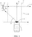
- a motor vehicle 11 and a radar sensor system 13 mounted to a front section of the motor vehicle 11.
- the radar sensor system 13 is preferably based on a millimeter wave radar sensor.
- a single channel radar sensor is preferred to minimize the production costs.
- a multiple channel radar sensor may be provided to enhance the detection performance.
- the radar sensor system 13 can be connected to an electronic processing device (not shown), for example an advanced emergency braking system, a pedestrian collision avoidance system or an autonomous driving system.
- the motor vehicle 11 is moving in a driving direction 15 on a lane 17.
- a pedestrian 19 crossing the lane 17 is moving in a moving direction 21.
- the moving direction 21 is at least essentially perpendicular to the driving direction 15. In principle, the moving direction 21 may be inclined to the driving direction 15.
- the radar sensor system 13 is configured for transmitting a primary radar signal into the traffic space 23 in front of the motor vehicle 11 and for detecting pedestrians 19 present in the traffic space 23 on the basis of a secondary radar signal reflected by the pedestrians 19.
- the line 25 which extends from the pedestrian 19 to the active region of the radar sensor system 13 is called "line of sight".
- the observed bulk speed v ob of the pedestrian 19, i. e. the speed component related to the pedestrian's torso 27 and oriented along the line of sight 25, can be determined in a known manner using the Doppler effect.
- the illumination angle ⁇ and the speed v are determined on the basis of a Micro-Doppler spectrogram analysis by means of the electronic processing device, as is explained in greater detail below.
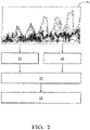
- a Micro-Doppler spectrogram 30 is generated as an input for the subsequent steps.
- the observed bulk speed v ob of the moving pedestrian 19 is determined based on the Micro-Doppler spectrogram 30.
- a gait cycle parameter in form of a gait cycle duration T gaitcycle of the moving pedestrian 19 is determined based on the Micro-Doppler spectrogram 30.
- the illumination angle ⁇ is determined based on the observed bulk speed v ob as determined in step 31 and the gait cycle parameter T gaitcycle as determined in step 32.
- the speed v of the moving pedestrian 19 in the moving direction 21 ( Fig. 1 ) is determined based on the observed bulk speed v ob as determined in step 31 and the illumination angle ⁇ as determined in step 33.
- the generation of the Micro-Doppler spectrogram 30 is carried out by means of a Short-Time-Fourier-Transform (STFT) or a Wigner-Ville-Distribution technique (WVD technique).
- STFT Short-Time-Fourier-Transform
- WVD technique Wigner-Ville-Distribution technique
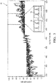
- An exemplary Micro-Doppler spectrogram 30 is shown in Fig. 3 .
- the horizontal axis is a time axis, whereas the vertical axis is a Doppler shift axis.
- a segment of the Micro-Doppler spectrogram 30 that corresponds to a gait cycle of the pedestrian 19.
- a gait cycle lasts from a ground contact of a certain foot to the next ground contact of this foot and thus usually corresponds to two consecutive footsteps.
- the periodic movement of the feet during walking generates an at least essentially periodic pattern in the Micro-Doppler spectrogram 30.
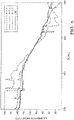
- Fig. 4 shows the right portion of the Micro-Doppler spectrogram 30 according to Fig. 3 in an enlarged view.
- Three curves corresponding to the courses of different motion components are shown in the Micro-Doppler spectrogram 30. Specifically, the course 40 of the observed bulk speed v ob is shown as a solid black line, whereas the upper envelope 41 of the Micro-Doppler spectrogram 30 and the lower envelope 42 of the Micro-Doppler spectrogram 30 are shown as dashed lines.
- the cumulative amplitude distribution function is determined for each time slice.
- the course 40 of the observed bulk speed v ob is assigned to a percentile of about 50% of the cumulative amplitude distribution function.
- the upper envelope 41 is assigned to a percentile of about 95% of the cumulative amplitude distribution function, whereas the lower envelope 42 is assigned to a percentile of about 5% of the cumulative amplitude distribution function.
- the repetition frequency of the gait cycle is estimated.
- the duration of the gait cycle T gaitcycle is the reciprocal of the repetition frequency of the gait cycle.
- T gaitcycle 1.346 v / H t wherein H t is the height of the pedestrian's thigh.
- H t is the height of the pedestrian's thigh.
- H t is the height of the pedestrian's thigh.
- H t is the height of the pedestrian's thigh.
- H t is the height of the pedestrian's thigh.
- H t is the height of the pedestrian's thigh
- H t 0.53 ⁇ H ped
- H ped is the pedestrian's height.
- N gaitcycle T gaitcycle
- Timebin 2 N footstep
- N footstep is the number of time-bins contained in a segment corresponding to one footstep.
- the factor 2 accounts for the above mentioned fact that usually one gait-cycle comprises two footsteps.
- the illumination angle ⁇ can be determined from equation (8).
- One variant for calculating the illumination angle ⁇ is to use equation (8) and to set H ped as the statistical average pedestrian height H ped_avg for the dedicated application scenario.
- the angle estimation error induced by the unknown pedestrian height is: ⁇ ⁇ ⁇ ⁇ v ped ob N footstep 2 KH ped_avg 2 H ped ⁇ H ped _ avg
- the angle estimation error is be below 6° for an illumination angle ⁇ varying between 60° and 120°, which is sufficient for most applications.
- the illumination angle ⁇ is always between 60° and 120°.
- Another variant of estimating the illumination angle ⁇ is to use a recursive state estimator such as an Extended Kalman Filter (EKF).
- EKF Extended Kalman Filter
- the subscripts n, n-1 indicate the current state and the previous state, respectively.
- the dot refers to the derivative of ⁇ .
- the illumination angle theta ⁇ can be estimated.
- Fig. 6 shows the estimated illumination angle ⁇ for a series of scans of the radar sensor system 13 ( Fig. 1 ).
- the EKF based method provides a more reliable estimation than methods based on exemplary fixed heights.
- H ped is a component of the state vector of the EKF as given in equation (10), it can also be estimated by the EKF.
- An example of such an estimation is shown in Fig. 7 .
- the invention enables a reliable recognition of moving pedestrians by means of a radar sensor system without the necessity to use complex and expensive hardware.
Landscapes
- Engineering & Computer Science (AREA)
- Remote Sensing (AREA)
- Radar, Positioning & Navigation (AREA)
- Physics & Mathematics (AREA)
- General Physics & Mathematics (AREA)
- Computer Networks & Wireless Communication (AREA)
- Human Computer Interaction (AREA)
- Multimedia (AREA)
- Theoretical Computer Science (AREA)
- Electromagnetism (AREA)
- Social Psychology (AREA)
- Psychiatry (AREA)
- Health & Medical Sciences (AREA)
- General Health & Medical Sciences (AREA)
- Computer Vision & Pattern Recognition (AREA)
- Radar Systems Or Details Thereof (AREA)
Claims (15)
- Procédé de reconnaissance d'un piéton en mouvement (19) au moyen d'un système de capteur radar (13), dans lequelun signal radar primaire est transmis jusque dans un espace d'observation (23), etun signal radar secondaire réfléchi par le piéton en mouvement (19) est reçu et traité,dans lequel le traitement du signal radar secondaire inclut les étapes consistant à :(i) générer un spectrogramme micro-Doppler (30) du signal radar secondaire,(ii) déterminer, sur la base du spectrogramme, une vitesse globale observée du piéton en mouvement (19), dans lequel la vitesse globale observée correspond à une composante de vitesse qui est en lien avec le torse du piéton (27) et est orientée le long d'une ligne de vue (25) s'étendant depuis le piéton en mouvement (19) jusqu'au système de capteur radar (13),(iii) déterminer, sur la base du spectrogramme micro-Doppler (30), au moins un paramètre de cycle de marche du piéton en mouvement (19), et(iv) déterminer, sur la base de la vitesse globale observée déterminée et dudit paramètre de cycle de marche déterminé, un angle d'illumination entre une direction de mouvement (21) du piéton en mouvement (19) et la ligne de vue (25).
- Procédé selon la revendication 1,
caractérisé en ce que
la vitesse du piéton en mouvement (19) dans la direction de mouvement (21) est déterminée sur la base de la vitesse globale observée déterminée et de l'angle d'illumination déterminé, en particulier en utilisant la formule :
- Procédé selon la revendication 1 ou 2,
caractérisé en ce que
le spectrogramme micro-Doppler (30) est généré au moyen d'une analyse temps-fréquence, en particulier au moyen d'une transformée de Fourier à court terme (STFT) ou d'une technique de distribution de Wigner-Ville (technique WVD). - Procédé selon l'une quelconque des revendications précédentes,
caractérisé en ce que
la vitesse globale observée est déterminée au moyen d'une méthode fondée sur les percentiles ou d'une méthode d'ajustement de courbes. - Procédé selon l'une quelconque des revendications précédentes,
caractérisé en ce que
ledit au moins un paramètre de cycle de marche est une durée moyenne du cycle de marche du piéton, une fréquence de répétition de cycles de marche moyenne ou un nombre de tranches temporelles liées à un cycle de marche. - Procédé selon l'une quelconque des revendications précédentes,
caractérisé en ce que
ledit au moins un paramètre de marche est déterminé au moyen d'une analyse de Fourier. - Procédé selon la revendication 6,
caractérisé en ce que
une transformée de Fourier rapide (FFT) est appliqué sur une enveloppe supérieure (41) et/ou sur une enveloppe inférieure (42) du spectrogramme micro-Doppler (30) pour estimer la fréquence de répétition du cycle de marche. - Procédé selon l'une quelconque des revendications précédentes,
caractérisé en ce que
l'étape (iv) inclut de mettre en relation ledit au moins un paramètre de cycle de marche déterminé avec la vitesse observée déterminée et avec une hauteur estimée de la cuisse du piéton en mouvement. - Procédé selon la revendication 8,
caractérisé en ce que
une relation est utilisée qui est basée sur un modèle humain cinématique. - Procédé selon la revendication 8 ou 9,
caractérisé en ce que
la hauteur de la cuisse du piéton en mouvement est estimée sur la base d'une relation entre la hauteur de la cuisse du piéton en mouvement et la hauteur totale du piéton (19), en particulier sur la base de la relation suivante :
- Procédé selon la revendication 10,
caractérisé en ce que
la hauteur totale du piéton en mouvement (19) est estimée sur la base d'une hauteur moyenne statistique de piétons. - Procédé selon l'une quelconque des revendications précédentes,
caractérisé en ce que
dans l'étape (iv), l'angle d'illumination est estimé au moyen d'un estimateur d'état récurrent, en particulier d'un filtre de Kalman étendu (EKF). - Système de reconnaissance d'un piéton en mouvement (19) comprenant :un système de capteur radar (13) destiné à transmettre un signal radar primaire jusque dans un espace d'observation et à recevoir un signal radar secondaire réfléchi par le piéton en mouvement (19), etun dispositif de traitement électronique destiné à traiter le signal radar secondaire,caractérisé en ce quele dispositif de traitement électronique est configuré pour exécuter un procédé selon l'une quelconque des revendications précédentes.
- Système selon la revendication 13,
caractérisé en ce que
le système de capteur radar (13) est configuré pour être monté sur ou dans un véhicule à moteur (11). - Produit de programme d'ordinateur incluant un code de programme exécutable qui, quand il est exécuté, amène un système selon la revendication 13 ou 14 à exécuter un procédé selon l'une quelconque des revendications 1 à 12.
Priority Applications (3)
| Application Number | Priority Date | Filing Date | Title |
|---|---|---|---|
| EP18166844.3A EP3553552B1 (fr) | 2018-04-11 | 2018-04-11 | Procédé de reconnaissance d'un piéton en mouvement |
| US16/361,897 US10929653B2 (en) | 2018-04-11 | 2019-03-22 | Method for the recognition of a moving pedestrian |
| CN201910279440.8A CN110361737B (zh) | 2018-04-11 | 2019-04-09 | 识别移动的行人的方法 |
Applications Claiming Priority (1)
| Application Number | Priority Date | Filing Date | Title |
|---|---|---|---|
| EP18166844.3A EP3553552B1 (fr) | 2018-04-11 | 2018-04-11 | Procédé de reconnaissance d'un piéton en mouvement |
Publications (2)
| Publication Number | Publication Date |
|---|---|
| EP3553552A1 EP3553552A1 (fr) | 2019-10-16 |
| EP3553552B1 true EP3553552B1 (fr) | 2022-05-25 |
Family
ID=61971970
Family Applications (1)
| Application Number | Title | Priority Date | Filing Date |
|---|---|---|---|
| EP18166844.3A Active EP3553552B1 (fr) | 2018-04-11 | 2018-04-11 | Procédé de reconnaissance d'un piéton en mouvement |
Country Status (3)
| Country | Link |
|---|---|
| US (1) | US10929653B2 (fr) |
| EP (1) | EP3553552B1 (fr) |
| CN (1) | CN110361737B (fr) |
Families Citing this family (14)
| Publication number | Priority date | Publication date | Assignee | Title |
|---|---|---|---|---|
| EP3553551B1 (fr) | 2018-04-10 | 2022-06-01 | Aptiv Technologies Limited | Procédé de reconnaissance d'un objet |
| EP3553559B1 (fr) | 2018-04-11 | 2022-06-01 | Aptiv Technologies Limited | Procédé de reconnaissance d'objets |
| DE102018205532B4 (de) * | 2018-04-12 | 2025-01-23 | Robert Bosch Gmbh | Verfahren zum Erkennen eines Hindernisses vor einem Fahrzeug |
| TWI734252B (zh) * | 2019-11-08 | 2021-07-21 | 立積電子股份有限公司 | 雷達及雷達回波訊號的背景成分更新方法 |
| EP4075162A4 (fr) * | 2019-12-09 | 2023-12-27 | Kyocera Corporation | Dispositif électronique, procédé de commande de dispositif électronique et programme |
| GB201919450D0 (en) | 2019-12-31 | 2020-02-12 | Essence Smartcare Ltd | A device for monitoring an environment |
| KR102227393B1 (ko) * | 2020-02-03 | 2021-03-15 | 재단법인대구경북과학기술원 | 도플러 정보 기반의 보행자 및 차량 인식 장치 및 그 방법 |
| US11415670B2 (en) | 2020-03-20 | 2022-08-16 | Aptiv Technologies Limited | Object classification using low-level radar data |
| JP2022085374A (ja) * | 2020-11-27 | 2022-06-08 | 京セラ株式会社 | 電子機器、電子機器の制御方法、及びプログラム |
| JP2022138848A (ja) * | 2021-03-11 | 2022-09-26 | マツダ株式会社 | レーダによる移動体検出方法 |
| CN113189555B (zh) * | 2021-04-12 | 2023-02-14 | 浙江大学 | 基于时-距包围盒目标截取的多目标分割方法、步态识别方法、装置、系统和存储介质 |
| US12463675B2 (en) * | 2021-08-05 | 2025-11-04 | Samsung Electronics Co., Ltd. | Radio frequency exposure estimation with radar for mobile devices |
| CN114089328A (zh) * | 2021-11-23 | 2022-02-25 | 扬州宇安电子科技有限公司 | 确定行人移动速度的方法及行人定位方法、车载雷达 |
| CN116453227B (zh) * | 2023-06-19 | 2023-09-19 | 武汉理工大学 | 一种基于双毫米波雷达的船舶环境下步态识别方法 |
Citations (1)
| Publication number | Priority date | Publication date | Assignee | Title |
|---|---|---|---|---|
| EP3553551A1 (fr) * | 2018-04-10 | 2019-10-16 | Aptiv Technologies Limited | Procédé de reconnaissance d'un objet |
Family Cites Families (37)
| Publication number | Priority date | Publication date | Assignee | Title |
|---|---|---|---|---|
| US4958638A (en) | 1988-06-30 | 1990-09-25 | Georgia Tech Research Corporation | Non-contact vital signs monitor |
| US5689268A (en) | 1996-08-02 | 1997-11-18 | Boeing North American, Inc. | Radar detection and classification of helicopters |
| US6653971B1 (en) | 1999-05-14 | 2003-11-25 | David L. Guice | Airborne biota monitoring and control system |
| US6121916A (en) | 1999-07-16 | 2000-09-19 | Eaton-Vorad Technologies, L.L.C. | Method and apparatus for recognizing stationary objects with a moving side-looking radar |
| WO2001073680A1 (fr) * | 2000-03-27 | 2001-10-04 | Massachusetts General Hospital | Procedes et systemes de reconnaissance d'individus par des parametres d'anatomie et de demarche |
| US7016782B2 (en) | 2002-05-30 | 2006-03-21 | Delphi Technologies, Inc. | Collision detection system and method of estimating miss distance |
| US6674394B1 (en) | 2003-03-28 | 2004-01-06 | Visteon Global Technologies, Inc. | Method for determining object location from side-looking sensor data |
| US20100074379A1 (en) | 2008-04-01 | 2010-03-25 | Ming-Chiang Li | Tuning replica generation methods and apparatus for their most optimum performance in processing transient signals |
| US20110102234A1 (en) | 2009-11-03 | 2011-05-05 | Vawd Applied Science And Technology Corporation | Standoff range sense through obstruction radar system |
| DE112010005662T5 (de) | 2010-06-16 | 2013-03-21 | Toyota Jidosha Kabushiki Kaisha | Objektidentifikationsvorrichtung und Verfahren |
| DE102010062235A1 (de) * | 2010-12-01 | 2012-06-06 | Robert Bosch Gmbh | Fahrerassistenzsystem zur Detektion eines Objekts in einer Fahrzeugumgebung |
| JP2012189338A (ja) * | 2011-03-08 | 2012-10-04 | Panasonic Corp | レーダ装置及び移動機器用レーダシステム |
| EP2589979A1 (fr) | 2011-11-03 | 2013-05-08 | Thales Nederland B.V. | Système de caractérisation de mouvement d'un individu, notamment un individu humain |
| DE102012107445B8 (de) * | 2012-08-14 | 2016-04-28 | Jenoptik Robot Gmbh | Verfahren zur Klassifizierung von fahrenden Fahrzeugen |
| US20200064444A1 (en) * | 2015-07-17 | 2020-02-27 | Origin Wireless, Inc. | Method, apparatus, and system for human identification based on human radio biometric information |
| US9594159B2 (en) * | 2013-07-15 | 2017-03-14 | Texas Instruments Incorporated | 2-D object detection in radar applications |
| WO2015144741A1 (fr) | 2014-03-27 | 2015-10-01 | Sony Corporation | Caméra avec système radar |
| US10809365B2 (en) | 2014-08-25 | 2020-10-20 | Texas Instruments Incorporated | Vibration parameters monitoring using FMCW radar |
| US10185030B2 (en) | 2014-09-05 | 2019-01-22 | GM Global Technology Operations LLC | Object boundary detection for automotive radar imaging |
| DE102014218092A1 (de) | 2014-09-10 | 2016-03-10 | Volkswagen Aktiengesellschaft | Erstellen eines Abbilds der Umgebung eines Kraftfahrzeugs und Bestimmen der relativen Geschwindigkeit zwischen dem Kraftfahrzeug und Objekten in der Umgebung |
| CN104330791B (zh) * | 2014-10-24 | 2017-03-29 | 上海无线电设备研究所 | 一种基于频域切变的相参积累方法 |
| CN104360336B (zh) | 2014-11-24 | 2017-02-08 | 电子科技大学 | 一种自适应提取雷达目标微动周期的新方法 |
| US10481696B2 (en) | 2015-03-03 | 2019-11-19 | Nvidia Corporation | Radar based user interface |
| EP3289432B1 (fr) | 2015-04-30 | 2019-06-12 | Google LLC | Suivi de micro-mouvements sur la base de rf pour suivi et reconnaissance de gestes |
| DE102015007040B4 (de) | 2015-05-30 | 2020-09-24 | Audi Ag | Verfahren zur Detektion und Klassifikation von Fußgängern in einer Umgebung eines Kraftfahrzeugs und Kraftfahrzeug |
| US9604639B2 (en) * | 2015-08-28 | 2017-03-28 | Delphi Technologies, Inc. | Pedestrian-intent-detection for automated vehicles |
| US10054672B2 (en) | 2015-08-31 | 2018-08-21 | Veoneer Us, Inc. | Apparatus and method for detecting and correcting for blockage of an automotive radar sensor |
| US10817065B1 (en) | 2015-10-06 | 2020-10-27 | Google Llc | Gesture recognition using multiple antenna |
| US10571562B2 (en) | 2016-03-25 | 2020-02-25 | Magna Electronics Inc. | Vehicle short range sensing system using RF sensors |
| JP2017223461A (ja) | 2016-06-13 | 2017-12-21 | パナソニックIpマネジメント株式会社 | レーダ装置および検出方法 |
| DE102016213007A1 (de) * | 2016-07-15 | 2018-01-18 | Robert Bosch Gmbh | Verfahren und System zur Abtastung eines Objekts |
| DE102016213254B3 (de) | 2016-07-20 | 2017-07-13 | Volkswagen Aktiengesellschaft | Verfahren zum Erfassen einer Objektbewegung eines Objekts in einer Umgebung eines Kraftfahrzeugs, Steuervorrichtung und Kraftfahrzeugs |
| JP6778873B2 (ja) * | 2016-08-10 | 2020-11-04 | パナソニックIpマネジメント株式会社 | レーダ設置角度算出装置、レーダ装置およびレーダ設置角度算出方法 |
| DE102016215102A1 (de) * | 2016-08-12 | 2017-12-07 | Conti Temic Microelectronic Gmbh | Fußgängererkennung mittels Radar |
| CN107358250B (zh) * | 2017-06-07 | 2019-11-22 | 清华大学 | 基于双波段雷达微多普勒融合的人体步态识别方法及系统 |
| US11295119B2 (en) * | 2017-06-30 | 2022-04-05 | The Johns Hopkins University | Systems and method for action recognition using micro-doppler signatures and recurrent neural networks |
| DE102017211432A1 (de) | 2017-07-05 | 2019-01-10 | Robert Bosch Gmbh | System zum Detektieren eines bewegten Objekts |
-
2018
- 2018-04-11 EP EP18166844.3A patent/EP3553552B1/fr active Active
-
2019
- 2019-03-22 US US16/361,897 patent/US10929653B2/en active Active
- 2019-04-09 CN CN201910279440.8A patent/CN110361737B/zh active Active
Patent Citations (1)
| Publication number | Priority date | Publication date | Assignee | Title |
|---|---|---|---|---|
| EP3553551A1 (fr) * | 2018-04-10 | 2019-10-16 | Aptiv Technologies Limited | Procédé de reconnaissance d'un objet |
Also Published As
| Publication number | Publication date |
|---|---|
| US20190318162A1 (en) | 2019-10-17 |
| US10929653B2 (en) | 2021-02-23 |
| CN110361737B (zh) | 2023-05-23 |
| EP3553552A1 (fr) | 2019-10-16 |
| CN110361737A (zh) | 2019-10-22 |
Similar Documents
| Publication | Publication Date | Title |
|---|---|---|
| EP3553552B1 (fr) | Procédé de reconnaissance d'un piéton en mouvement | |
| US11131766B2 (en) | Method for the recognition of an object | |
| CN110832340B (zh) | 用于探测运动对象的系统 | |
| US9971022B2 (en) | Radar apparatus | |
| US11249180B2 (en) | Method and device for ascertaining transverse relative velocity components of radar targets | |
| KR102427165B1 (ko) | 객체 스캐닝 방법 및 그 시스템 | |
| EP2741100B1 (fr) | Appareil radar et son procédé de traitement des signaux | |
| JP3385304B2 (ja) | 車載用レーダ装置 | |
| JP2020091281A (ja) | レーダーデータを処理する装置及び方法 | |
| US9812008B2 (en) | Vehicle detection and tracking based on wheels using radar and vision | |
| JP7173735B2 (ja) | レーダ装置及び信号処理方法 | |
| CN111615641B (zh) | 用于探测关键横向运动的方法和设备 | |
| KR101752651B1 (ko) | 레이더 시스템의 클러터 제거 및 다중 표적 추적방법 | |
| JP6993136B2 (ja) | レーダ装置および物標検知方法 | |
| Schubert et al. | A multi-reflection-point target model for classification of pedestrians by automotive radar | |
| EP3290945A1 (fr) | Détection de désalignement pour un capteur de radar de véhicule | |
| US20050004719A1 (en) | Device and method for determining the position of objects in the surroundings of a motor vehicle | |
| CN110678776B (zh) | 用于增强的对象跟踪的系统 | |
| JP7167871B2 (ja) | 物標検出装置 | |
| Kapse et al. | Implementing an autonomous emergency braking with simulink using two radar sensors | |
| KR20150001393A (ko) | 레이더 배열 안테나 빔 감지 장치 및 방법 | |
| CN114089328A (zh) | 确定行人移动速度的方法及行人定位方法、车载雷达 | |
| Schubert et al. | Target modeling and deduction of automotive radar resolution requirements for pedestrian classification | |
| JP2008026239A (ja) | レーダ | |
| Nair et al. | Dual Radar System for Predicting Collisions at Uncontrolled Intersections |
Legal Events
| Date | Code | Title | Description |
|---|---|---|---|
| PUAI | Public reference made under article 153(3) epc to a published international application that has entered the european phase |
Free format text: ORIGINAL CODE: 0009012 |
|
| STAA | Information on the status of an ep patent application or granted ep patent |
Free format text: STATUS: THE APPLICATION HAS BEEN PUBLISHED |
|
| AK | Designated contracting states |
Kind code of ref document: A1 Designated state(s): AL AT BE BG CH CY CZ DE DK EE ES FI FR GB GR HR HU IE IS IT LI LT LU LV MC MK MT NL NO PL PT RO RS SE SI SK SM TR |
|
| AX | Request for extension of the european patent |
Extension state: BA ME |
|
| STAA | Information on the status of an ep patent application or granted ep patent |
Free format text: STATUS: REQUEST FOR EXAMINATION WAS MADE |
|
| 17P | Request for examination filed |
Effective date: 20200320 |
|
| RBV | Designated contracting states (corrected) |
Designated state(s): AL AT BE BG CH CY CZ DE DK EE ES FI FR GB GR HR HU IE IS IT LI LT LU LV MC MK MT NL NO PL PT RO RS SE SI SK SM TR |
|
| RIC1 | Information provided on ipc code assigned before grant |
Ipc: G01S 13/46 20060101ALN20211104BHEP Ipc: G01S 13/931 20200101ALI20211104BHEP Ipc: G01S 13/58 20060101ALI20211104BHEP Ipc: G01S 7/41 20060101AFI20211104BHEP |
|
| GRAP | Despatch of communication of intention to grant a patent |
Free format text: ORIGINAL CODE: EPIDOSNIGR1 |
|
| STAA | Information on the status of an ep patent application or granted ep patent |
Free format text: STATUS: GRANT OF PATENT IS INTENDED |
|
| INTG | Intention to grant announced |
Effective date: 20211210 |
|
| GRAS | Grant fee paid |
Free format text: ORIGINAL CODE: EPIDOSNIGR3 |
|
| GRAA | (expected) grant |
Free format text: ORIGINAL CODE: 0009210 |
|
| STAA | Information on the status of an ep patent application or granted ep patent |
Free format text: STATUS: THE PATENT HAS BEEN GRANTED |
|
| AK | Designated contracting states |
Kind code of ref document: B1 Designated state(s): AL AT BE BG CH CY CZ DE DK EE ES FI FR GB GR HR HU IE IS IT LI LT LU LV MC MK MT NL NO PL PT RO RS SE SI SK SM TR |
|
| REG | Reference to a national code |
Ref country code: GB Ref legal event code: FG4D |
|
| REG | Reference to a national code |
Ref country code: CH Ref legal event code: EP |
|
| REG | Reference to a national code |
Ref country code: AT Ref legal event code: REF Ref document number: 1494480 Country of ref document: AT Kind code of ref document: T Effective date: 20220615 Ref country code: DE Ref legal event code: R096 Ref document number: 602018035914 Country of ref document: DE |
|
| REG | Reference to a national code |
Ref country code: IE Ref legal event code: FG4D |
|
| REG | Reference to a national code |
Ref country code: LT Ref legal event code: MG9D |
|
| REG | Reference to a national code |
Ref country code: NL Ref legal event code: MP Effective date: 20220525 |
|
| REG | Reference to a national code |
Ref country code: AT Ref legal event code: MK05 Ref document number: 1494480 Country of ref document: AT Kind code of ref document: T Effective date: 20220525 |
|
| PG25 | Lapsed in a contracting state [announced via postgrant information from national office to epo] |
Ref country code: SE Free format text: LAPSE BECAUSE OF FAILURE TO SUBMIT A TRANSLATION OF THE DESCRIPTION OR TO PAY THE FEE WITHIN THE PRESCRIBED TIME-LIMIT Effective date: 20220525 Ref country code: PT Free format text: LAPSE BECAUSE OF FAILURE TO SUBMIT A TRANSLATION OF THE DESCRIPTION OR TO PAY THE FEE WITHIN THE PRESCRIBED TIME-LIMIT Effective date: 20220926 Ref country code: NO Free format text: LAPSE BECAUSE OF FAILURE TO SUBMIT A TRANSLATION OF THE DESCRIPTION OR TO PAY THE FEE WITHIN THE PRESCRIBED TIME-LIMIT Effective date: 20220825 Ref country code: NL Free format text: LAPSE BECAUSE OF FAILURE TO SUBMIT A TRANSLATION OF THE DESCRIPTION OR TO PAY THE FEE WITHIN THE PRESCRIBED TIME-LIMIT Effective date: 20220525 Ref country code: LT Free format text: LAPSE BECAUSE OF FAILURE TO SUBMIT A TRANSLATION OF THE DESCRIPTION OR TO PAY THE FEE WITHIN THE PRESCRIBED TIME-LIMIT Effective date: 20220525 Ref country code: HR Free format text: LAPSE BECAUSE OF FAILURE TO SUBMIT A TRANSLATION OF THE DESCRIPTION OR TO PAY THE FEE WITHIN THE PRESCRIBED TIME-LIMIT Effective date: 20220525 Ref country code: GR Free format text: LAPSE BECAUSE OF FAILURE TO SUBMIT A TRANSLATION OF THE DESCRIPTION OR TO PAY THE FEE WITHIN THE PRESCRIBED TIME-LIMIT Effective date: 20220826 Ref country code: FI Free format text: LAPSE BECAUSE OF FAILURE TO SUBMIT A TRANSLATION OF THE DESCRIPTION OR TO PAY THE FEE WITHIN THE PRESCRIBED TIME-LIMIT Effective date: 20220525 Ref country code: ES Free format text: LAPSE BECAUSE OF FAILURE TO SUBMIT A TRANSLATION OF THE DESCRIPTION OR TO PAY THE FEE WITHIN THE PRESCRIBED TIME-LIMIT Effective date: 20220525 Ref country code: BG Free format text: LAPSE BECAUSE OF FAILURE TO SUBMIT A TRANSLATION OF THE DESCRIPTION OR TO PAY THE FEE WITHIN THE PRESCRIBED TIME-LIMIT Effective date: 20220825 Ref country code: AT Free format text: LAPSE BECAUSE OF FAILURE TO SUBMIT A TRANSLATION OF THE DESCRIPTION OR TO PAY THE FEE WITHIN THE PRESCRIBED TIME-LIMIT Effective date: 20220525 |
|
| PG25 | Lapsed in a contracting state [announced via postgrant information from national office to epo] |
Ref country code: RS Free format text: LAPSE BECAUSE OF FAILURE TO SUBMIT A TRANSLATION OF THE DESCRIPTION OR TO PAY THE FEE WITHIN THE PRESCRIBED TIME-LIMIT Effective date: 20220525 Ref country code: PL Free format text: LAPSE BECAUSE OF FAILURE TO SUBMIT A TRANSLATION OF THE DESCRIPTION OR TO PAY THE FEE WITHIN THE PRESCRIBED TIME-LIMIT Effective date: 20220525 Ref country code: LV Free format text: LAPSE BECAUSE OF FAILURE TO SUBMIT A TRANSLATION OF THE DESCRIPTION OR TO PAY THE FEE WITHIN THE PRESCRIBED TIME-LIMIT Effective date: 20220525 Ref country code: IS Free format text: LAPSE BECAUSE OF FAILURE TO SUBMIT A TRANSLATION OF THE DESCRIPTION OR TO PAY THE FEE WITHIN THE PRESCRIBED TIME-LIMIT Effective date: 20220925 |
|
| PG25 | Lapsed in a contracting state [announced via postgrant information from national office to epo] |
Ref country code: SM Free format text: LAPSE BECAUSE OF FAILURE TO SUBMIT A TRANSLATION OF THE DESCRIPTION OR TO PAY THE FEE WITHIN THE PRESCRIBED TIME-LIMIT Effective date: 20220525 Ref country code: SK Free format text: LAPSE BECAUSE OF FAILURE TO SUBMIT A TRANSLATION OF THE DESCRIPTION OR TO PAY THE FEE WITHIN THE PRESCRIBED TIME-LIMIT Effective date: 20220525 Ref country code: RO Free format text: LAPSE BECAUSE OF FAILURE TO SUBMIT A TRANSLATION OF THE DESCRIPTION OR TO PAY THE FEE WITHIN THE PRESCRIBED TIME-LIMIT Effective date: 20220525 Ref country code: EE Free format text: LAPSE BECAUSE OF FAILURE TO SUBMIT A TRANSLATION OF THE DESCRIPTION OR TO PAY THE FEE WITHIN THE PRESCRIBED TIME-LIMIT Effective date: 20220525 Ref country code: DK Free format text: LAPSE BECAUSE OF FAILURE TO SUBMIT A TRANSLATION OF THE DESCRIPTION OR TO PAY THE FEE WITHIN THE PRESCRIBED TIME-LIMIT Effective date: 20220525 Ref country code: CZ Free format text: LAPSE BECAUSE OF FAILURE TO SUBMIT A TRANSLATION OF THE DESCRIPTION OR TO PAY THE FEE WITHIN THE PRESCRIBED TIME-LIMIT Effective date: 20220525 |
|
| REG | Reference to a national code |
Ref country code: DE Ref legal event code: R097 Ref document number: 602018035914 Country of ref document: DE |
|
| RAP4 | Party data changed (patent owner data changed or rights of a patent transferred) |
Owner name: APTIV TECHNOLOGIES LIMITED |
|
| PG25 | Lapsed in a contracting state [announced via postgrant information from national office to epo] |
Ref country code: AL Free format text: LAPSE BECAUSE OF FAILURE TO SUBMIT A TRANSLATION OF THE DESCRIPTION OR TO PAY THE FEE WITHIN THE PRESCRIBED TIME-LIMIT Effective date: 20220525 |
|
| PLBE | No opposition filed within time limit |
Free format text: ORIGINAL CODE: 0009261 |
|
| STAA | Information on the status of an ep patent application or granted ep patent |
Free format text: STATUS: NO OPPOSITION FILED WITHIN TIME LIMIT |
|
| 26N | No opposition filed |
Effective date: 20230228 |
|
| PG25 | Lapsed in a contracting state [announced via postgrant information from national office to epo] |
Ref country code: SI Free format text: LAPSE BECAUSE OF FAILURE TO SUBMIT A TRANSLATION OF THE DESCRIPTION OR TO PAY THE FEE WITHIN THE PRESCRIBED TIME-LIMIT Effective date: 20220525 |
|
| P01 | Opt-out of the competence of the unified patent court (upc) registered |
Effective date: 20230424 |
|
| REG | Reference to a national code |
Ref country code: CH Ref legal event code: PL |
|
| PG25 | Lapsed in a contracting state [announced via postgrant information from national office to epo] |
Ref country code: LU Free format text: LAPSE BECAUSE OF NON-PAYMENT OF DUE FEES Effective date: 20230411 |
|
| REG | Reference to a national code |
Ref country code: BE Ref legal event code: MM Effective date: 20230430 |
|
| PG25 | Lapsed in a contracting state [announced via postgrant information from national office to epo] |
Ref country code: MC Free format text: LAPSE BECAUSE OF FAILURE TO SUBMIT A TRANSLATION OF THE DESCRIPTION OR TO PAY THE FEE WITHIN THE PRESCRIBED TIME-LIMIT Effective date: 20220525 |
|
| PG25 | Lapsed in a contracting state [announced via postgrant information from national office to epo] |
Ref country code: MC Free format text: LAPSE BECAUSE OF FAILURE TO SUBMIT A TRANSLATION OF THE DESCRIPTION OR TO PAY THE FEE WITHIN THE PRESCRIBED TIME-LIMIT Effective date: 20220525 Ref country code: LI Free format text: LAPSE BECAUSE OF NON-PAYMENT OF DUE FEES Effective date: 20230430 Ref country code: IT Free format text: LAPSE BECAUSE OF FAILURE TO SUBMIT A TRANSLATION OF THE DESCRIPTION OR TO PAY THE FEE WITHIN THE PRESCRIBED TIME-LIMIT Effective date: 20220525 Ref country code: CH Free format text: LAPSE BECAUSE OF NON-PAYMENT OF DUE FEES Effective date: 20230430 |
|
| REG | Reference to a national code |
Ref country code: IE Ref legal event code: MM4A |
|
| PG25 | Lapsed in a contracting state [announced via postgrant information from national office to epo] |
Ref country code: BE Free format text: LAPSE BECAUSE OF NON-PAYMENT OF DUE FEES Effective date: 20230430 |
|
| PG25 | Lapsed in a contracting state [announced via postgrant information from national office to epo] |
Ref country code: IE Free format text: LAPSE BECAUSE OF NON-PAYMENT OF DUE FEES Effective date: 20230411 |
|
| PG25 | Lapsed in a contracting state [announced via postgrant information from national office to epo] |
Ref country code: IE Free format text: LAPSE BECAUSE OF NON-PAYMENT OF DUE FEES Effective date: 20230411 |
|
| PG25 | Lapsed in a contracting state [announced via postgrant information from national office to epo] |
Ref country code: BG Free format text: LAPSE BECAUSE OF FAILURE TO SUBMIT A TRANSLATION OF THE DESCRIPTION OR TO PAY THE FEE WITHIN THE PRESCRIBED TIME-LIMIT Effective date: 20220525 |
|
| PG25 | Lapsed in a contracting state [announced via postgrant information from national office to epo] |
Ref country code: BG Free format text: LAPSE BECAUSE OF FAILURE TO SUBMIT A TRANSLATION OF THE DESCRIPTION OR TO PAY THE FEE WITHIN THE PRESCRIBED TIME-LIMIT Effective date: 20220525 |
|
| REG | Reference to a national code |
Ref country code: DE Ref legal event code: R081 Ref document number: 602018035914 Country of ref document: DE Owner name: APTIV TECHNOLOGIES AG, CH Free format text: FORMER OWNER: APTIV TECHNOLOGIES LIMITED, ST. MICHAEL, BB |
|
| PGFP | Annual fee paid to national office [announced via postgrant information from national office to epo] |
Ref country code: DE Payment date: 20250313 Year of fee payment: 8 |
|
| PG25 | Lapsed in a contracting state [announced via postgrant information from national office to epo] |
Ref country code: CY Free format text: LAPSE BECAUSE OF FAILURE TO SUBMIT A TRANSLATION OF THE DESCRIPTION OR TO PAY THE FEE WITHIN THE PRESCRIBED TIME-LIMIT; INVALID AB INITIO Effective date: 20180411 |
|
| PG25 | Lapsed in a contracting state [announced via postgrant information from national office to epo] |
Ref country code: HU Free format text: LAPSE BECAUSE OF FAILURE TO SUBMIT A TRANSLATION OF THE DESCRIPTION OR TO PAY THE FEE WITHIN THE PRESCRIBED TIME-LIMIT; INVALID AB INITIO Effective date: 20180411 |
|
| PG25 | Lapsed in a contracting state [announced via postgrant information from national office to epo] |
Ref country code: TR Free format text: LAPSE BECAUSE OF FAILURE TO SUBMIT A TRANSLATION OF THE DESCRIPTION OR TO PAY THE FEE WITHIN THE PRESCRIBED TIME-LIMIT Effective date: 20220525 |
|
| PGFP | Annual fee paid to national office [announced via postgrant information from national office to epo] |
Ref country code: GB Payment date: 20260305 Year of fee payment: 9 |
|
| PGFP | Annual fee paid to national office [announced via postgrant information from national office to epo] |
Ref country code: FR Payment date: 20260303 Year of fee payment: 9 |