EP3553420B1 - Strenge temperaturregelung bei thermischer belastung mit einem zweiphasigen pumpkreislauf, optional ergänzt durch einen dampfkompressionszyklus - Google Patents
Strenge temperaturregelung bei thermischer belastung mit einem zweiphasigen pumpkreislauf, optional ergänzt durch einen dampfkompressionszyklus Download PDFInfo
- Publication number
- EP3553420B1 EP3553420B1 EP19162071.5A EP19162071A EP3553420B1 EP 3553420 B1 EP3553420 B1 EP 3553420B1 EP 19162071 A EP19162071 A EP 19162071A EP 3553420 B1 EP3553420 B1 EP 3553420B1
- Authority
- EP
- European Patent Office
- Prior art keywords
- coolant
- pressure
- vapor
- vcs
- tppl
- Prior art date
- Legal status (The legal status is an assumption and is not a legal conclusion. Google has not performed a legal analysis and makes no representation as to the accuracy of the status listed.)
- Active
Links
Images

Classifications
-
- F—MECHANICAL ENGINEERING; LIGHTING; HEATING; WEAPONS; BLASTING
- F25—REFRIGERATION OR COOLING; COMBINED HEATING AND REFRIGERATION SYSTEMS; HEAT PUMP SYSTEMS; MANUFACTURE OR STORAGE OF ICE; LIQUEFACTION SOLIDIFICATION OF GASES
- F25B—REFRIGERATION MACHINES, PLANTS OR SYSTEMS; COMBINED HEATING AND REFRIGERATION SYSTEMS; HEAT PUMP SYSTEMS
- F25B23/00—Machines, plants or systems, with a single mode of operation not covered by groups F25B1/00 - F25B21/00, e.g. using selective radiation effect
- F25B23/006—Machines, plants or systems, with a single mode of operation not covered by groups F25B1/00 - F25B21/00, e.g. using selective radiation effect boiling cooling systems
-
- F—MECHANICAL ENGINEERING; LIGHTING; HEATING; WEAPONS; BLASTING
- F28—HEAT EXCHANGE IN GENERAL
- F28D—HEAT-EXCHANGE APPARATUS, NOT PROVIDED FOR IN ANOTHER SUBCLASS, IN WHICH THE HEAT-EXCHANGE MEDIA DO NOT COME INTO DIRECT CONTACT
- F28D15/00—Heat-exchange apparatus with the intermediate heat-transfer medium in closed tubes passing into or through the conduit walls ; Heat-exchange apparatus employing intermediate heat-transfer medium or bodies
- F28D15/02—Heat-exchange apparatus with the intermediate heat-transfer medium in closed tubes passing into or through the conduit walls ; Heat-exchange apparatus employing intermediate heat-transfer medium or bodies in which the medium condenses and evaporates, e.g. heat pipes
- F28D15/06—Control arrangements therefor
-
- F—MECHANICAL ENGINEERING; LIGHTING; HEATING; WEAPONS; BLASTING
- F25—REFRIGERATION OR COOLING; COMBINED HEATING AND REFRIGERATION SYSTEMS; HEAT PUMP SYSTEMS; MANUFACTURE OR STORAGE OF ICE; LIQUEFACTION SOLIDIFICATION OF GASES
- F25B—REFRIGERATION MACHINES, PLANTS OR SYSTEMS; COMBINED HEATING AND REFRIGERATION SYSTEMS; HEAT PUMP SYSTEMS
- F25B25/00—Machines, plants or systems, using a combination of modes of operation covered by two or more of the groups F25B1/00 - F25B23/00
- F25B25/005—Machines, plants or systems, using a combination of modes of operation covered by two or more of the groups F25B1/00 - F25B23/00 using primary and secondary systems
-
- F—MECHANICAL ENGINEERING; LIGHTING; HEATING; WEAPONS; BLASTING
- F28—HEAT EXCHANGE IN GENERAL
- F28D—HEAT-EXCHANGE APPARATUS, NOT PROVIDED FOR IN ANOTHER SUBCLASS, IN WHICH THE HEAT-EXCHANGE MEDIA DO NOT COME INTO DIRECT CONTACT
- F28D15/00—Heat-exchange apparatus with the intermediate heat-transfer medium in closed tubes passing into or through the conduit walls ; Heat-exchange apparatus employing intermediate heat-transfer medium or bodies
- F28D15/02—Heat-exchange apparatus with the intermediate heat-transfer medium in closed tubes passing into or through the conduit walls ; Heat-exchange apparatus employing intermediate heat-transfer medium or bodies in which the medium condenses and evaporates, e.g. heat pipes
- F28D15/025—Heat-exchange apparatus with the intermediate heat-transfer medium in closed tubes passing into or through the conduit walls ; Heat-exchange apparatus employing intermediate heat-transfer medium or bodies in which the medium condenses and evaporates, e.g. heat pipes having non-capillary condensate return means
-
- F—MECHANICAL ENGINEERING; LIGHTING; HEATING; WEAPONS; BLASTING
- F28—HEAT EXCHANGE IN GENERAL
- F28D—HEAT-EXCHANGE APPARATUS, NOT PROVIDED FOR IN ANOTHER SUBCLASS, IN WHICH THE HEAT-EXCHANGE MEDIA DO NOT COME INTO DIRECT CONTACT
- F28D15/00—Heat-exchange apparatus with the intermediate heat-transfer medium in closed tubes passing into or through the conduit walls ; Heat-exchange apparatus employing intermediate heat-transfer medium or bodies
- F28D15/02—Heat-exchange apparatus with the intermediate heat-transfer medium in closed tubes passing into or through the conduit walls ; Heat-exchange apparatus employing intermediate heat-transfer medium or bodies in which the medium condenses and evaporates, e.g. heat pipes
- F28D15/0266—Heat-exchange apparatus with the intermediate heat-transfer medium in closed tubes passing into or through the conduit walls ; Heat-exchange apparatus employing intermediate heat-transfer medium or bodies in which the medium condenses and evaporates, e.g. heat pipes with separate evaporating and condensing chambers connected by at least one conduit; Loop-type heat pipes; with multiple or common evaporating or condensing chambers
-
- F—MECHANICAL ENGINEERING; LIGHTING; HEATING; WEAPONS; BLASTING
- F28—HEAT EXCHANGE IN GENERAL
- F28F—DETAILS OF HEAT-EXCHANGE AND HEAT-TRANSFER APPARATUS, OF GENERAL APPLICATION
- F28F27/00—Control arrangements or safety devices specially adapted for heat-exchange or heat-transfer apparatus
- F28F27/02—Control arrangements or safety devices specially adapted for heat-exchange or heat-transfer apparatus for controlling the distribution of heat-exchange media between different channels
Definitions
- This disclosure relates generally to cooling systems.
- the cooling system further includes a control unit for maintaining pressure of system coolant at a system coolant supply side of the coolant branches within a specific pressure range at or above saturation pressure of the system coolant for a given desired saturation temperature of system coolant into the evaporators to facilitate two-phase heat transfer in the plurality of evaporators from the electronic devices to the system coolant at the given desired saturation temperature.
- the present disclosure provides a two-phase pump loop (TPPL) for dissipating a thermal load during operation of an apparatus, and a thermal management system for dissipating a thermal load during operation of an apparatus, as set out in the appended claims.
- TPPL two-phase pump loop
- a two-phase pump loop for dissipating a thermal load during operation of an apparatus;
- the TPPL comprising: a vapor/liquid receiver configured to store a coolant; a pump configured to force the coolant to flow through the TPPL; an evaporator configured to absorb heat (Q ABSORBED ) from the apparatus, the evaporator having an inlet and an outlet; a condenser configured to release heat (Q REJETED ) in order to remove the heat (Q REJECTED ) from the TPPL; a valve (V 1 ) configured to regulate a pressure or temperature of the coolant exiting the evaporator; the V 1 having a control set point set at a first pressure (P 1set ) to achieve an evaporator exit pressure that is a saturation pressure (P H ) for the coolant at a predetermined exit temperature from the evaporator; a valve (V 2 ) having a control set point set at a second pressure (P 2
- the two-phase pump loop may further comprise a liquid return valve; and a liquid separator in fluid communication with the outlet of the evaporator; the liquid separator configured to return a substantial portion of the liquid portion of the coolant through the liquid return valve to the vapor/liquid receiver.
- the TPPL may further comprise a sensor configured to measure the level of liquid in the liquid separator in order to control the flow through the liquid return valve.
- the TPPL may be integrated with a vapor cycle system (VCS).
- VCS vapor cycle system
- the VCS may be configured to remove heat from the TPPL when the temperature of the coolant flowing through the inlet of the evaporator is about ambient temperature or less than ambient temperature.
- the V 1 and V 2 may be independently selected to be an expansion valve, a pressure reducing valve, or a back pressure regulator.
- a thermal management system for dissipating a thermal load during operation of an apparatus; the thermal management system comprising a two-phase pump loop (TPPL) according to the first aspect and a primary vapor cycle system (p-VCS) that is configured to use the same coolant and to be in fluid communication through the vapor/liquid receiver, wherein the p-VCS comprises: the vapor/liquid receiver configured to store the coolant; the condenser configured so that the coolant releases heat (Q REJECTED ) in order to remove heat (Q REJECTED ) from the thermal management system; a first compressor; the valve (V 2 ) having a control set point set at a second pressure (P 2set ) to prevent the vapor/liquid receiver pressure from going to a pressure/temperature that is lower than a predetermined value (P L ); the controller configured to control the set points of V 1 and V 2 ; wherein the controller is configured to set P 1set so as to provide a predetermined temperature at the outlet of the e
- TPPL two
- control set points of V 2 and V 3 may be variable in order to balance the heat (Q REJECTED ) removed from the condenser with the heat (Q ABSORBED ) absorbed at the evaporator along with any other heat additions or losses encountered.
- the p-VCS may comprise a second compressor located parallel to the compressor in order to minimize power draw.
- the V 1 , V 2 , and V 3 may be independently selected to be an expansion valve, a pressure reducing valve, or a back pressure regulator.
- the thermal management system may further comprise a secondary vapor cycle system (s-VCS) configured to operate at a lower temperature than the p-VCS and may be able to operate at a smaller thermal load or to operate when the p-VSC is not operational; wherein the s-VCS may comprise: a phase change material (PCM) located in an evaporator/condenser (PCM/Ev/Cnd), the PCM providing thermal energy storage by absorbing heat until the p-VCS, the s-VCS, or both the p-VCS and s-VCS are operational; an accumulator; an expansion valve; a third compressor configured to force a the coolant to flow to the vapor/liquid receiver or to the condenser; a controller configured to control the expansion valve such that only vapor enters the third compressor; and a plurality of valves configured to allow the s-VCS to use the condenser located in the p-VCS when the p-VCS is turned off or to allow the coolant to
- Such an apparatus or device includes, without limitation, solid state electronics, a light-emitting diode (LED), an analog circuit, a digital circuit, a computer, a server, a server farm, a data center, a hoteling circuit such as vehicle electronics, a vehicle, an aircraft, a directed-energy weapon, a laser, a plasma weapon, a railgun, a microwave generator, a pulse-powered device, a satellite uplink, an electric motor generator, an electric device, or the like.
- solid state electronics such as solid state electronics, a light-emitting diode (LED), an analog circuit, a digital circuit, a computer, a server, a server farm, a data center, a hoteling circuit such as vehicle electronics, a vehicle, an aircraft, a directed-energy weapon, a laser, a plasma weapon, a railgun, a microwave generator, a pulse-powered device, a satellite uplink, an electric motor generator, an electric device, or the like.
- LED light-emitting diode
- valve for the purpose of this disclosure, the terms “valve”, “expansion valve”, “pressure reducing valve”, and “back pressure regulator” or “BPR” may be used interchangeably in the description of a component in the two-phase pump loop (TPPL) and are intended to provide substantially similar or the same performance.
- TPPL two-phase pump loop
- valve is intended to indicate a plurality of valves in which each valve is independently selected to be an expansion valve, pressure reducing valve, or a back pressure regulator.
- the terms “at least one” and “one or more of' an element are used interchangeably and may have the same meaning. These terms, which refer to the inclusion of a single element or a plurality of the elements, may also be represented by the suffix "(s)"at the end of the element. For example, “at least one source”, “one or more sources”, and “source(s)” may be used interchangeably and are intended to have the same meaning.
- the term "tight" temperature control describes controlling a temperature condition with minimal variation, such as ⁇ 5°C; alternatively, ⁇ 3°C; alternatively, ⁇ 1°C; alternatively, ⁇ 0.5°C.
- this control over the variation in temperature may also be expressed as a percentage of the measured temperature. For example, as the measured temperature is controlled to be within ⁇ 10%; alternatively, ⁇ 5%; alternatively, ⁇ 3%; alternatively, ⁇ 1 %.
- the challenge for maintaining the temperature/pressure in a closed two-phase pump loop system The system receives heat in the evaporator on the left and rejects the heat from a condenser on the right.
- the pressure of the system will vary depending on heat loads.
- the condenser will for a while reject more heat than the evaporator is receiving from the heat load. In this condition, the overall system temperature/pressure will begin to fall. This will result in the liquid in the receiver getting colder.
- a heat load imbalance is expected to occur due to heat loads that are highly transient. One could vary the amount of heat removed from the condenser; however, most control schemes are expected to be relatively slow in responding relative to the rate of change in the load in the evaporator.
- VCS Vapor Cycle Systems
- a primary VCS has control features to quickly restore high cooling capacity after the VCS has been placed in a low power consumption status.
- a secondary VCS has the ability to provide cooling at a different temperature/pressure and manage low power loads.
- concepts are provided within the present disclosure that minimize the electrical power consumption required to run the system.
- V 1 25 may be located after the condenser 20a as shown in Figure 2A , or if enhanced temperature control is desired, the V 1 25 may be located prior to the condenser 20a without exceeding the scope of the present disclosure.
- back pressure regulators are described throughout the present disclosure, one skilled in the art will understand that the substitution of the back pressure regulators with other types of pressure reducing valves are contemplated to be within the scope of the present disclosure.
- the V 1 25 has a pressure set point (P 1set ) such that the pressure at or after the exit of the load evaporator 5 is the saturation pressure (P H ) that is required to give the proper coolant temperature in the load evaporator 5.
- P 1set is set to achieve an evaporator exit pressure that is the saturation pressure (P H ) of the coolant 3 at a predetermined or desired target exit temperature from the evaporator 5.
- the set point pressure (P 1set ) is expected to be slightly lower than the saturation pressure (P H ) due to expected pressure losses in the line from the load evaporator to the V 1 25 device.
- V 1 25 will not prevent the coolant 3 in the vapor/liquid receiver 15 from getting colder than the temperature that is required at the inlet to the load evaporator 5.
- V 2 a second valve
- the V 2 30 manages how much heat QREJECTED is actually pulled from the TPPL system 1.
- a flow restriction 35 may be present at or near the outlet of V 2 30, upstream of V 2 30, or anywhere along the flow pathway associated with V 2 30. Reducing the coolant 3 flow to the condenser 20a reduces QREJECTED and returns heat to the vapor/liquid receiver 15. This will prevent the vapor/liquid receiver 15 from becoming excessively cold and thus keeps the fluid going to the load evaporator 5 at an acceptable temperature.
- the condenser 20a may be cooled with a cold water-fluid mixture (e.g., water-polypropylene glycol mixture, etc.) from a previously chilled tank of liquid or it could be cooled with a cold air stream.
- a cold water-fluid mixture e.g., water-polypropylene glycol mixture, etc.
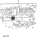
- the two-phase pump loop (TPPL) 1 generally comprises, consists of, or consists essentially of a vapor/liquid receiver 15 configured to store a coolant 3; a pump 10 configured to force the coolant 3 to flow through lines or tubes throughout the TPPL 1; an evaporator 5 configured to absorb heat (Q ABSORBED ) from the apparatus, the evaporator 5 comprising an inlet 7 and an outlet 9; a condenser 20a configured to release heat (Q REJECTED ) in order to remove the heat (Q REJECTED ) from the TPPL 1; and a valve (V 1 ) 25 configured to regulate a pressure at an outlet of the condenser 20a, the V 1 25 having a control set point at a first pressure (P 1set ); a valve (V 2 ) 30 having a control set point set at a second pressure (P 2set ); and a controller configured to control the set points of V 1 and V 2 .
- the controller 23 may be any device that performs logic operations.
- the controller 23 may be in communication with a memory (not shown). Alternatively or in addition, the controller 23 may be in communication with multiple components within the TPPL 1.
- the controller 23 may include a general processor, a central processing unit, a server device, an application specific integrated circuit (ASIC), a digital signal processor, a field programmable gate array (FPGA), a digital circuit, an analog circuit, a microcontroller, any other type of processor, or any combination thereof.
- the controller 23 may include one or more elements operable to execute computer executable instructions or computer code embodied in the memory.
- the memory may be any device for storing and retrieving data or any combination thereof.
- the memory may include non-volatile and/or volatile memory, such as a random access memory (RAM), a read-only memory (ROM), an erasable programmable read-only memory (EPROM), or flash memory.
- RAM random access memory
- ROM read-only memory
- EPROM erasable programmable read-only memory
- flash memory Alternatively or in addition, the memory may include an optical, magnetic (hard-drive) or any other form of data storage device.
- the TPPL 1 is configured to cool the thermal load with tight control of the temperature of the coolant 3 that is cooling the apparatus.
- the control set point of V 1 25 is varied to balance the heat (Q REJECTED ) removed from coolant 3 at the condenser 20a with the heat (Q ABSORBED ) absorbed by the coolant 3 at the evaporator 5.
- the phrase "to balance the heat (Q REJECTED ) with the heat (Q ABSORBED )” refers to the heat (Q REJECTED ) being equal to the sum of the heat (Q ABSORBED ) plus any other heat additions or losses encountered during the operation of the system.
- the condenser 20a should not remove more heat than is being put into the system at the load evaporator 5. Therefore, when desirable or necessary the cooling performed at the condenser 20a may be reduced. This reduction is achieved by not sending all of the coolant 3 to the condenser 20a by lowering the P 2set so that some of the coolant 3 is passed through V 2 30. In the extreme, if no heat is being added to the evaporator 5, almost all of the coolant 3 would be passed through V 2 30. In this way, the pressure and/or temperature in the vapor/liquid receiver 15 is managed so that the receiver 15 is not overcooled. This will assure that the temperature of the coolant 3 entering load evaporator 5 doesn't get too cold
- the outlet of the vapor-liquid receiver 15 includes a means of creating a pressure rise. More specifically, a pump 10 is located approximate to the exit of the vapor/liquid receiver 15 in order to create flow of the coolant 3 to the load evaporator 5. The pump 10 should draw liquid coolant 3 from the vapor/liquid receiver 15.
- the vapor-liquid receiver 15 may include any device configured to separate a vapor-liquid mixture into vapor and liquid portions.
- the vapor-liquid receiver 15 may be a vessel in which gravity causes the liquid portion to settle to a bottom portion of the vessel and the vapor portion to rise to a top portion of the vessel.
- the evaporator 5 used in conjunction with the TPPL 1 may be made smaller by selecting appropriate heat exchanger core designs for its construction without exceeding the scope of the present disclosure. More specifically, the important features of this evaporator 5 include the ability to transfer heat, the evacuation of any evaporated liquid, and the containment of pressure.
- a diffusion-bonded structure such as applied to the design and construction of turbine airfoils may be used to form the evaporator 5.
- a diffusion-bonded structure includes complex heat transfer and fluid flow passages. The rules, tools, and manufacturing techniques employed in designing actively cooled turbines directly applies to the problem of providing for the cooling of an apparatus - with the addition of two-phase heat transfer and pressure drop calculations.
- the TPPL 1 as shown in Figures 2A and 2B may be built with existing commercial off-the-shelf valves, e.g., back pressure regulators.
- the valves are very good at maintaining an upstream pressure, even as the fluid passing through it can vary in quality (e.g., ratio of vapor flow to total mass flow).
- the design can have the pressure set point P 2set changed very quickly, i.e., on the order of about 100 milliseconds. Therefore, a controller 23 can determine the proper pressure set point for V 2 25 as a function of the pressure in the vapor/liquid receiver 15. As the pressure in the vapor/liquid receiver 15 falls, the V 2 30 set point can be lowered below V 1 25 to begin to pass more of the fluid through V 2 30.
- a small downstream or upstream flow restriction 35 may be necessary to help with stability of the system.
- the two valves, V 1 25 and V 2 30, balance the heat QREJECTED removed from the coolant 3 at the condenser 20a with the heat Q ABSORBED absorbed by the coolant 3 at the evaporator 5 plus any other heat additions or losses encountered during the operation of the system.
- An alternative design may be to use a pressure reducing valve in place of a back pressure regulator at V 2 30.
- the pressure reducing valve will remain closed until the pressure in the vapor/liquid receiver 15 falls below a set value, which may reduce the need to actively control the set point pressure in the V 2 30 location.
- Other types of valves could also be considered based on their ability to control flow rates in order to control pressure of the vapor/liquid receiver 15 and evaporator exit 9.
- the TPPL 1 may be modified to minimize challenges associated with two-phase flow.
- the fluid that exits from the load evaporator has the liquid and vapor separated.
- a liquid separator 40 is placed downstream of the load evaporator 5 and is in fluid communication with the outlet of evaporator 5. This will provide a more uniform quality to the flow of coolant 3 to V2 30.
- This flow of coolant 3 to V 2 30 need not be pure vapor, but a very high quality of flow will enable a more consistent mass flow rate through V 2 30 for a given valve opening and pressure difference across the valve. This would enable the use of a wider variety of valves to replace V 2 30. It is not critical that all the liquid be separated, but only a significant portion.
- the liquid separator 40 is configured to return all or a portion of the separated liquid coolant 3 through a liquid return valve 45 to the vapor/liquid receiver 15. Alternatively, about 99% to 100% of the liquid coolant 3 is returned.
- the pressure difference between the tanks will drive the liquid flow.
- a sensor could be used to measure the level of liquid in the separator in order to control the flow through the liquid return valve and then use the liquid control valve 45 to manage the height of that liquid.
- V 2 30 could be replaced with a pressure-reducing valve without exceeding the scope of the present disclosure when the flow of the coolant 3 to V 2 30 is nearly all vapor and the pressure-reducing valve doesn't exhibit too large of a variation in pressure drop versus flow rate.
- the liquid separator 40 may use centrifugal force to drive the liquid portion towards an outer edge of the vessel for removal and the vapor portion may migrate towards a center region of the vessel.
- the liquid separator 40 may include a level sensor mechanism that monitors a level of the liquid in the vessel.
- the TPPL 1 may be integrated with a vapor cycle system (VCS) 50 in which the VCS 50 is configured to remove heat from the TPPL 1 when the temperature of the coolant 3 flowing through the inlet of the evaporator 5 is about ambient temperature or substantially less than ambient temperature.
- VCS vapor cycle system
- ambient temperature includes an evaporator inlet temperature that is slightly greater than ambient temperature; alternatively, ⁇ 5°C of ambient temperature; alternatively, ⁇ 2.5°C; alternatively, ⁇ 1°C; alternatively, ⁇ 0.5°C.
- the TPPL 1 behaves the same as the prior embodiment shown in Figures 2A and 3 .
- a challenge in this system is how to manage the condition when the heat load in the load evaporator becomes very low. In this case, when the heat load on the VCS 50 becomes very low, it may be difficult to have the VCS 50 at low cooling capacities and to then to rapidly provide high levels of cooling. Options for quickly recovering high cooling capacity after operating at lower heat loads include the incorporation of one of a hot gas bypass loop or reducing the pressure drop across an expansion valve into the VCS 50.
- the TPPL 1 may be incorporated into a thermal management system 53 in order to dissipate a thermal load during operation of an apparatus.
- the thermal management system 53 may comprise the two-phase pump loop (TPPL) 1 as previously described and further defined herein, and a primary vapor cycle system (p-VCS) 50a that are configured to use the same coolant 3 and to be in fluid communication through a vapor/liquid receiver 15.
- TPPL two-phase pump loop
- p-VCS primary vapor cycle system
- V 3 70 is added to function as an expansion valve in the VCS 50A.
- the set point (P 3set ) of V 3 70 is set to maintain a predetermined pressure at an exit of the compressor 60a.
- the V 3 70 set point (P 3set ) pressure is increased in order to allow the compressor 60a to increase the coolant 3 pressure and therefore temperature, to be able to reject heat from the condenser 20b to the available heat sink (e.g. air) and therefore to provide cooling to the coolant 3.
- V 2 30 set point pressure may be reduced to be less than the V 3 70 set point pressure. In so doing, less coolant 3 is passed through condenser 20b and overcooling of the vapor/liquid receiver 15 is avoided. It is possible that V 3 70 and V 2 30 could also use conventional electronically controlled expansion valves.
- a coarse cooling capacity adjustment may be achieved by slowing the compressor 20b and the fans for condenser air heat sink.
- using these approaches may prevent the VCS 50a from rapidly ramping up to provide sufficient cooling capacity in the event of a sudden load increase.
- the pressure set points for V 2 30 and V 3 70 may be varied to manage cooling capacity. Assuming initially that P 2set > P 3set , the set point pressure on V 3 70 may be reduced to lower the power consumption in the compressor 20b and the cooling provided from the VCS 50a. If the volume between the compressor 60a and the valves V 3 , V 2 is sufficiently small, the cooling capacity of the VCS 50a can be rapidly restored by increasing the V 3 set point pressure (P 3set ).
- the pressure set point in V 2 30 may be varied to be slightly below the set point of V 3 70. This will result in less coolant 3 being cooled as it is passing through the condenser 20b.
- recuperators 65a. 65b for superheat management of the flow entering the compressor 20b. The fluid exiting the vapor/liquid receiver 15 and flowing to the compressor 20b will be at saturated conditions and may also have some entrained liquid. The recuperators 65a, 65b would add heat and avoid passing liquid to the compressor 20b.
- a more conventional expansion valve could be used.
- the TPPL 1 generally comprises: the vapor/liquid receiver 15 configured to store the coolant 3; a pump 10 configured to force the coolant 3 to flow through lines or tubes throughout the TPPL 1; an evaporator 5 having an inlet 7 and an outlet 9 that is configured to absorb heat (Q ABSORBED ) from the apparatus; a valve (V 1 ) 25 having a control set point set at a first pressure (P 1set ) to establish the proper pressure at P H measured at the outlet 9 of the evaporator 5, the P 1set being less than a saturation pressure (P H ) of the coolant 3
- the p-VCS 50A generally comprises: the vapor/liquid receiver 15 configured to store the coolant 3; a condenser 20b configured so that the coolant 3 releases heat (Q REJECTED ) in order to remove heat (Q REJECTED ) from the thermal management system 53; a valve (V 2 ) 30 having a control set point set at a second pressure (P 2set ), the P 2set being set higher or lower than P 3set to control the amount of flow through condenser 20b; a compressor 60a; a valve (V 3 ) 70 configured to act as an expansion valve; the V 3 70 having a control set point (P 3set ) set to maintain a predetermined pressure (P CMP ) at the outlet of the compressor 20b; one or more recuperators 65a, 65b configured with condenser exit flow or hot bypass flow to prevent any coolant 3 in liquid form from entering the compressor 60a; and a controller 23 configured to control the set points of V 1 , V 2 , and
- the controller 23 is configured to set P 1set in order to provide a predetermined temperature at the outlet of the evaporator 5 and the controller 23 is configured to vary P 2set and P 3set in order to maintain the proper amount of cooling in order to maintain the pressure in the vapor/liquid receiver 15 at P L .
- the V 2 is configured to allow a portion of the coolant 3 exiting the compressor 60a to flow back into the vapor/liquid receiver 15 in order to prevent overcooling of the vapor/liquid receiver while allowing the compressor to continue to run.
- the control set points of V 2 and V 3 are variable in order to balance the heat (Q REJECTED ) removed from the coolant 3 at the condenser with the heat (Q ABSORBED ) absorbed by the coolant 3 at the evaporator. More specifically, the heat (Q REJECTED ) is equal to the sum of the heat (Q ABSORBED ) plus any other heat additions or losses encountered during the operation of the system. These other heat additions or losses may occur, without limitation, through the operation of compressors, pumps, and other system components.
- sensors may be utilized to measure and monitor the pressure and/or temperature at or near the outlet of the evaporator and in the vapor/liquid receiver without exceeding the scope of the present disclosure.
- Figure 5A provides a system with greater operability, and reduces the overall system size and weight since the VCS 50A has the same working fluid as the TPPL 1.
- the p-VCS 50a may comprise a second compressor 60b located parallel to the compressor 60a in order to minimize power draw.
- This lower power, lower temperature cooling may also be achieved by incorporating a secondary vapor cycle system (s-VCS) 80.
- the original, high power VCS is called the primary vapor cycle system (p-VCS) 50a.
- the s-VCS 80 generally comprises a phase change material (PCM) located in an evaporator/condenser (PCM/Ev/Cnd) 90, the PCM providing thermal energy storage by absorbing heat until the p-VSC 50a is operational; an accumulator 83; a third compressor 85 configured to force a portion of the coolant 3 to flow to the vapor/liquid receiver 15; and a plurality of valves 99A-99D; wherein at least one valve 99A is configured to manage the use of the PCM/Ev/Cnd 90 and the other valves 99B-99D are configured to allow the s-VCS 80 to share the use of the condenser 20b located in the p-VCS 50a or to allow a portion of the coolant 3 to flow to the vapor/liquid receiver 15.
- PCM phase change material
- PCM/Ev/Cnd evaporator/condenser
- the s-VCS 80 may also comprise an expansion valve 95 that is in fluid communication with the outlet of the vapor/liquid receiver 15. This expansion valve 95 is to pass liquid coolant 3.
- a feedback loop established between the outlet of the PCM/Ev/Cnd 90 and the expansion valve 95 is configured to maintain a superheat condition at the inlet of compressor 85.
- the controller 23 may be used to control the expansion valve such that only vapor enters the third compressor.
- the compressors 60a, 60b, 85 may be any mechanical device that increases a pressure of a gas by reducing the volume of the gas.
- the compressors may be used in conjunction with an oil receiver when desirable.
- Examples of a compressor 60a, 60b, 85 may include but not be limited to any gas compressor, such as a positive displacement compressor, a dynamic compressor, a rotary compressor, a reciprocating compressor, a centrifugal compressor, an axial compressor, and/or any combination thereof.
- the thermal management system 53 described in Figure 5B provides thermal energy storage and the ability to more quickly bring high cooling capability on-line.
- the secondary VCS 80 expands liquid contained in the vapor/liquid receiver 15.
- the expanded coolant 3 cools the low temperature heat load 93 and also provides cooling to the load evaporator 5 when that heat load is very small or the primary VCS 50a is not operational.
- the secondary VCS may be used. In this low load condition, valve 99A bypasses the phase change material (PCM).
- the PCM/Ev/Cnd 90 can also allow periods for the compressor 60a, 60b, 85 to be shut-off in order to avoid operation under very poor efficiency conditions.
- the PCM/Ev/Cnd 90 can condense the vapor from the load evaporator 5 during this time period. If the melt temperature is suitably chosen, it may also extend the period of time that the coolant 3 can be expanded for cooling the low temperature heat load 93 while compressor 85 is turned off and thereby allow a smaller accumulator 83 or extend the period of time that compressor 20b can be turned off. During this period, with the compressor turned off, the vapor exiting the low temperature heat load 93, would be condensed in the PCM/Ev/Cnd 90. For this to work, the lower temperature low heat load 93 would need to be able to have its operating temperature rise above the melting point of the PCM.
- the temperature requirement for the low temperature heat load 93 is a range of temperatures.
- the melt temperature of the PCM in the PCM/Ev/Cnd 90 could be set between the high and low temperature limit 93.
- the low temperature load 93 could be operating to the low end of this temperature tolerance, thus freezing the PCM.
- the coolant 3 could still be expanded through the expansion valve 95. However, as this occurs the pressure in the low temperature loop will rise, increasing the operating temperature.
- valve 99b would be open while valves 99c and 99d would be closed in order to use the large condenser area available in the primary VCS 50a and thereby reduce compressor pressure ratio requirements.
- valve 99b would be closed, while vales 99c and 99d are open.
- the third compressor 85 sends coolant to the vapor/liquid receiver 15.
- multiple compressors 60a, 60b are used to manage cooling capacity. If the heat load is reduced to relatively low, one of the compressors (60a or 60b) may be turned off in order to operate closer to peak efficiency and to reduce system power requirements.
- all compressors 60a, 60b, 85 could be driven by battery supplied power so that the compressors can quickly be ramped up to produce cooling while waiting for the prime mover generator power supply to come on-line. This will minimize the amount of PCM required. Also, multiple primary compressors 60a, 60b are implemented in order to reduce power requirements for the compressor(s) when the heat load to be cooled is much less than the maximum cooling capacity of the system.
- the amount of coolant 3 in the VCS 50a would need to be larger than the amount required to support steady state operation. This additional mass would make it more difficult to perform the initial chill down of the VCS 50a, because of the large amount thermal energy that must be removed from the coolant 3. Therefore, it may be necessary to sequester the additional coolant that is needed for TES into a separate tank. This would allow the VCS 50a and TPPL 1 to more quickly chill down to the required operating temperatures. Once the steady state operating condition is reached, the VCS 50a could continue with the chilling of the sequestered coolant to the operating temperature and then to continue chilling the full coolant charge to a temperature necessary to provide sufficient thermal storage capacity.
- the TPPL 1 and VCS 50 utilize the same coolant 3.
- the vapor from the TPPL 1 is condensed with the chilled coolant 3b that is injected into the 2-phase stream 3a of the TPPL 1 at a predetermined location 201, which represents a nozzle.
- the colder coolant 3b will absorb heat from the vapor, resulting in the vapor condensing.
- the VCS 50 is configured to operate at a temperature that is equal to or lower than the temperature of the evaporator in the TPPL.
- the VCS 50 generally comprises: a low pressure receiver (LPR) 105 configured to store the coolant 3; a condenser 20b configured to release heat (Q REJECTED ) in order to remove the heat (Q REJECTED ) from the thermal management system 53 and to cool the coolant 3b below the temperature of coolant 3a; a pump 110 configured to force the cooled liquid coolant 3b to flow from the LPR 105 of the VCS 50 to the flow of coolant 3a that is downstream of evaporator 5 of the TPPL 1; a recuperator 65 configured to prevent the coolant 3 in liquid form from entering the compressor 60a; an expansion valve 67 configured to control the exit pressure of the compressor 60a and to reduce the coolant's pressure in order to lower the coolant's temperature; and a variable speed pump, or a variable area nozzle, or both to control the injection flow rate of cold coolant in order to keep the vapor/liquid receiver pressure nominally at P L and to replenish coolant mass in the vapor/liquid receiver; a valve (
- the valve (V 2 ) 30 maintains this pressure, by restricting flow to the low pressure receiver (LPR) in the VCS 50. If the pressure drops below P L , the valve (V 2 ) 30 closes. Dropping below this pressure may happen if the cold coolant is injected too quickly. However, the valve (V 2 ) 30 is generally open and will pass vapor there through when the pressure in the LPR goes above P L .
- the vapor/liquid receiver 15 of the TPPL 1 further comprises a foam or porous structure configured to assist in condensing the coolant 3 from a vapor to a liquid.
- the VCS 50 may also comprise a second pump 115 configured to remove a portion of the coolant 3 from the LPR 105, to flow said portion of the coolant 3 to a secondary thermal load 120 in order to absorb heat therefrom, and to return the heated portion of the coolant 3 to the LPR 105.
- the LPR 105 may further comprise a segmented region 106 wherein a portion of the coolant 3 that provides thermal energy storage is sequestered.
- the cold coolant 3b could be injected directly into the two-phase stream 3a.
- the cold coolant 3b may be pressurized by the pump 110 and then injected into the two-phase stream 3a.
- the goal is to create fine droplets in order to increase the droplet surface area/volume ratio to improve vapor condensation.
- the two-phase mixture vapor and subcooled liquid
- This foam or porous barrier could be made from foam metal, sintered beads, strips of material, or the like.
- a benefit of the concept shown in Figure 6 is that no heat exchanger is needed for condensing the vapor.
- the subcooled liquid will reach the temperature of the vapor, and hence the full TES capability of the cold coolant will be utilized.
- the full utilization of the TES will require less chilled coolant (smaller LPR) or not require that the coolant to be cooled to as low of temperature (allows a lower compressor pressure ratio) or the ability to reduce the time it takes to chill the coolant in the LPR.
- the second valve (V 2 ) 30 is used that will pass vapor back to the LPR 105.
- the second valve V 2 30 will prevent the LPR 105 from reaching too high of pressure and thus too high of temperature.
- This second valve (V 2 ) 30 may also keep the pressure greater than (or equal to) the pressure in the LPR 105.
- the V 2 30 is intended to maintain pressure in the receiver at P L .
- the V 2 30 may be opened to keep the pressure from getting too high. If the pressure goes below P L , then V 2 30 will close in order to allow the LPR 105 to repressurize.
- the amount of vapor to be removed from the vapor/liquid receiver 15 is equal to the amount of mass injected.
- the rate of injection will be a function of at least Q ABSORBED and the temperature of the injected stream 3b.
- the amount of cold coolant to be injected may be controlled by the speed of the pump 110 or the amount that nozzle 201 is opened. The speed or nozzle area may be controlled with the controller 23 as shown in Figure 6 .
Landscapes
- Engineering & Computer Science (AREA)
- Physics & Mathematics (AREA)
- Mechanical Engineering (AREA)
- Thermal Sciences (AREA)
- General Engineering & Computer Science (AREA)
- Life Sciences & Earth Sciences (AREA)
- Sustainable Development (AREA)
- Cooling Or The Like Of Electrical Apparatus (AREA)
- Separation By Low-Temperature Treatments (AREA)
- Air Conditioning Control Device (AREA)
- Heat-Pump Type And Storage Water Heaters (AREA)
Claims (10)
- Zweiphasen-Pumpschleife (TPPL, 1) zum Ableiten einer thermischen Last während eines Betriebs einer Vorrichtung; die TPPL umfassend:einen Dampf-/Flüssigkeitssammelbehälter (15), der konfiguriert ist, um ein Kühlmittel (3) zu speichern;eine Pumpe (10), die konfiguriert ist, um das Kühlmittel zu forcieren, durch die TPPL zu fließen;einen Verdampfer (5), der konfiguriert ist, um Wärme (QABSORBIERT) von der Vorrichtung zu absorbieren, wobei der Verdampfer einen Einlass (7) und einen Auslass (9) aufweist;einen Kondensator (20a), der konfiguriert ist, um Wärme abzugeben (QABGESONDERT), um die Wärme (QABGESONDERT) von der TPPL abzuleiten;dadurch gekennzeichnet, dass die TPPL ferner Folgendes umfasst:ein Ventil (V1, 25), das konfiguriert ist, um einen Druck oder eine Temperatur des Kühlmittels, das aus dem Verdampfer austritt, zu regeln; wobei das V1 eine Steuervorgabe aufweist, die auf einen ersten Druck (P1Vorgabe) eingestellt ist, um einen Verdampferausgangsdruck zu erreichen, der ein Sättigungsdruck (PH) für das Kühlmittel bei einer vorbestimmten Ausgangstemperatur aus dem Verdampfer ist;ein Ventil (V2, 30), das eine Steuervorgabe aufweist, die auf einen zweiten Druck (P2Vorgabe) eingestellt ist, um zu verhindern, dass der Druck des Dampf-/Flüssigkeitssammelbehälters auf einen Druck/eine Temperaturwert sinkt, der/die niedriger als ein vorbestimmter Wert (PL) ist; undeine Steuerung (23), die konfiguriert ist, um die Vorgaben von V1 und V2 zu steuern, wobei die Steuerung konfiguriert ist, um er P1Vorgabe einzustellen, um eine vorbestimmte Temperatur an dem Auslass des Verdampfers bereitzustellen, und die Steuerung konfiguriert ist, um P2Vorgabe zu variieren, um den Druck in dem Dampf-/Flüssigkeitssammelbehälter auf oder über PL zu halten;wobei die TPPL (1) konfiguriert ist, um die thermische Last mit einer engen Steuerung der Temperatur des Kühlmittels (3), das die Vorrichtung kühlt, zu kühlen.
- Zweiphasen-Pumpenkreislauf (TPPL) nach Anspruch 1, wobei die Steuervorgabe von V2 variiert wird, um die aus dem Kondensator (20a) abgeleitete Wärme (QABGESONDERT) mit der an dem Verdampfer (5) absorbierten Wärme (QABSORBIERT) zusammen mit anderen Wärmeadditionen oder -verlusten auszugleichen.
- Zweiphasen-Pumpenkreislauf (TPPL) nach Anspruch 1 oder Anspruch 2, wobei die TPPL ferner Folgendes umfasst;
ein Flüssigkeitsrücklaufventil (45); und
einen Flüssigkeitsabscheider (40) in Fluidverbindung mit dem Auslass (9) des Verdampfers (5); wobei der Flüssigkeitsabscheider konfiguriert ist, um einen wesentlichen Teil des Flüssigkeitsanteils des Kühlmittels (3) durch das Flüssigkeitsrücklaufventil zu dem Dampf-/Flüssigkeitssammelbehälter (15) zurückzuleiten. - Zweiphasen-Pumpenkreislauf (TPPL) nach Anspruch 3, wobei die TPPL ferner einen Sensor umfasst, der konfiguriert ist, um den Flüssigkeitsstand in dem Flüssigkeitsabscheider (40) zu messen, um den Fluss durch das Flüssigkeitsrücklaufventil (45) zu steuern.
- Zweiphasen-Pumpschleife (TPPL) nach einem der vorherigen Ansprüche, wobei die TPPL in ein Dampfkreislaufsystem (vapor cycle system, VCS, 50) integriert ist; das VCS konfiguriert ist, um Wärme von der TPPL abzuleiten, wenn die Temperatur des Kühlmittels (3), das durch den Einlass (7) des Verdampfers (5) fließt, etwa auf Umgebungstemperatur oder weniger als Umgebungstemperatur ist.
- Zweiphasen-Pumpenkreislauf (TPPL) nach Anspruch 5, wobei das V1 (25) und V2 (30) unabhängig ausgewählt sind, um ein Expansionsventil, ein Druckreduzierventil oder ein Gegendruckregler zu sein.
- Wärmemanagementsystem (53) zum Abführen einer Wärmelast während eines Betriebs einer Vorrichtung; das Wärmemanagementsystem umfassend eine Zweiphasen-Pumpschleife (TPPL, 1) nach einem der Ansprüche 1 bis 6 und ein primäres Dampfkreislaufsystem (p-VCS, 50a), das konfiguriert ist, um das gleiche Kühlmittel (3) zu verwenden und durch den Dampf-/Flüssigkeitssammelbehälter (15) in Fluidverbindung zu sein.
- Wärmemanagementsystem nach Anspruch 7,
wobei das p-VCS (50a) Folgendes umfasst:den Dampf-/Flüssigkeitssammelbehälter (15), der konfiguriert ist, um das Kühlmittel (3) zu speichern;den Kondensator (20a), der konfiguriert ist, sodass das Kühlmittel Wärme (QABGESONDERT) abgibt, um Wärme (QABGESONDERT) aus dem Wärmemanagementsystem abzuleiten;einen ersten Verdichter (60a);das Ventil (V2, 30), das eine Steuervorgabe aufweist, die auf einen zweiten Druck (P2Vorgabe) eingestellt ist, um zu verhindern, dass der Druck des Dampf-/Flüssigkeitssammelbehälters auf einen Druck/eine Temperaturwert sinkt, der/die niedriger als ein vorbestimmter Wert (PL) ist;die Steuerung (23), die konfiguriert ist, um die Vorgaben von V1 und V2 zu steuern, wobei die Steuerung konfiguriert ist, um er P1Vorgabe einzustellen, um eine vorbestimmte Temperatur an dem Auslass des Verdampfers bereitzustellen, und die Steuerung konfiguriert ist, um P2Vorgabe zu variieren, um den Druck in dem Dampf-/Flüssigkeitssammelbehälter auf oder über PL zu halten;ein Ventil (V3, 70), das konfiguriert ist, um als ein Expansionsventil wirkt; wobei das V3 eine Steuervorgabe aufweist, die eingestellt ist, um einen vorbestimmten Druck an einem Auslass des Verdichters zu halten; undeinen oder mehrere Wärmetauscher (55a, 65b), die mit einem Kondensatorausgangsstrom oder einem Heißgas-Bypassstrom konfiguriert sind, um zu verhindern, dass Kühlmittel in flüssiger Form in den Verdichter gelangt;wobei V2 konfiguriert ist, um zu ermöglichen, dass ein Teil des aus dem Kompressor austretenden Kühlmittels in den Dampf-/Flüssigkeitssammelbehälters (15) zurückströmt, um eine Überkühlung des Dampf/Flüssigkeitssammelbehälters zu verhindern, während der Kompressor weiterlaufen kann. - Wärmemanagementsystem (53) nach Anspruch 8, wobei die Steuervorgabe von V2 und V3 variabel sind, um die aus dem Kondensator (20a) abgeleitete Wärme (Qabgesondert) mit der an dem Verdampfer (5) absorbierten Wärme (QABSORBIERT) zusammen mit anderen Wärmeadditionen oder -verlusten auszugleichen; und/oder
wobei das p-VCS (50a) optional einen zweiten Verdichter umfasst, der parallel zu dem Verdichter angeordnet ist, um eine Leistungsaufnahme zu minimieren, und/oder wobei optional das V1, V2 und V3 unabhängig ausgewählt sind, um ein Expansionsventil, ein Druckreduzierventil oder ein Gegendruckregler zu sein. - Wärmemanagementsystem (53) nach Anspruch 8 oder 9, wobei das Wärmemanagementsystem ferner ein sekundäres Dampfkreislaufsystem (s-VCS, 80) umfasst, das konfiguriert ist, um bei einer niedrigeren Temperatur als das p-VCS (50a) betrieben zu werden und in der Lage ist, bei einer geringeren Wärmelast betrieben zu werden, oder betrieben zu werden, wenn das p-VSC nicht in Betrieb ist;
wobei das s-VCS (80) Folgendes umfasst:ein Phasenwechselmaterial (phase change material, PCM), das sich in einem Verdampfer/Kondensator (PCM/Ev/Cnd) befindet, wobei das PCM Wärmeenergie speichert, indem es Wärme absorbiert, bis das p-VCS, das s-VCS oder sowohl das p-VCS als auch das s-VCS betriebsbereit sind;einen Akkumulator (83);ein Expansionsventil (95); einen dritten Kompressor (85), der konfiguriert ist, um das Kühlmittel (3) zu forcieren, zu dem Dampf-/Flüssigkeitssammelbehälter (15) oder zu dem Kondensator zu fließen;eine Steuerung, die konfiguriert ist, um das Expansionsventil zu steuern, sodass nur Dampf in den dritten Verdichter gelangt; undeine Vielzahl von Ventilen, die konfiguriert sind, um dem s-VCS (80) zu ermöglichen, den in dem p-VCS befindlichen Kondensator zu verwenden, wenn das p-VCS ausgeschaltet ist, oder zu ermöglichen, dass das Kühlmittel zu dem Dampf-/Flüssigkeitssammelbehälter fließt, wenn das p-VCS in Betrieb ist, undoptional, wobei einer oder mehrere der Verdichter unter Verwendung einer Batteriestromquelle betrieben werden.
Applications Claiming Priority (2)
| Application Number | Priority Date | Filing Date | Title |
|---|---|---|---|
| US201862656491P | 2018-04-12 | 2018-04-12 | |
| US16/058,222 US10775110B2 (en) | 2018-04-12 | 2018-08-08 | Tight temperature control at a thermal load with a two phase pumped loop, optionally augmented with a vapor compression cycle |
Publications (3)
| Publication Number | Publication Date |
|---|---|
| EP3553420A2 EP3553420A2 (de) | 2019-10-16 |
| EP3553420A3 EP3553420A3 (de) | 2019-11-13 |
| EP3553420B1 true EP3553420B1 (de) | 2021-02-17 |
Family
ID=65766865
Family Applications (1)
| Application Number | Title | Priority Date | Filing Date |
|---|---|---|---|
| EP19162071.5A Active EP3553420B1 (de) | 2018-04-12 | 2019-03-12 | Strenge temperaturregelung bei thermischer belastung mit einem zweiphasigen pumpkreislauf, optional ergänzt durch einen dampfkompressionszyklus |
Country Status (2)
| Country | Link |
|---|---|
| US (1) | US10775110B2 (de) |
| EP (1) | EP3553420B1 (de) |
Families Citing this family (18)
| Publication number | Priority date | Publication date | Assignee | Title |
|---|---|---|---|---|
| US11839062B2 (en) | 2016-08-02 | 2023-12-05 | Munters Corporation | Active/passive cooling system |
| US10578369B1 (en) * | 2018-02-23 | 2020-03-03 | United States Of America As Represented By The Secretary Of The Air Force | Thermal management using endothermic heat sink |
| CN111358068B (zh) * | 2020-04-17 | 2024-09-17 | 宁波艾思吉制冷设备有限公司 | 一种高温作业液冷服 |
| EP4139985B1 (de) * | 2020-04-22 | 2024-08-14 | Volvo Truck Corporation | Elektrisches energiespeichersystem für ein fahrzeug |
| ES2889698B2 (es) * | 2020-06-24 | 2023-04-28 | Seat Sa | Sistema de refrigeración de al menos un elemento a refrigerar para un vehículo |
| US11162388B1 (en) | 2020-08-12 | 2021-11-02 | Rolls-Royce North American Technologies Inc. | Thermal management system to cool transient heat loads with low power consumption |
| US11530844B2 (en) | 2020-09-30 | 2022-12-20 | Rolls-Royce North American Technologies Inc. | System for supporting intermittent fast transient heat loads |
| CN112229105B (zh) * | 2020-10-14 | 2022-07-26 | 北京空间飞行器总体设计部 | 控温装置及泵驱两相流体回路系统 |
| US11212948B1 (en) * | 2021-03-09 | 2021-12-28 | Rolls-Royce North American Technologies Inc. | Thermal management system for tightly controlling temperature of a thermal load |
| US11959669B2 (en) | 2021-05-06 | 2024-04-16 | Rolls-Royce North American Technologies Inc. | Bimodal cooling system |
| US11781817B2 (en) * | 2021-06-22 | 2023-10-10 | Booz Allen Hamilton Inc. | Thermal management systems for extended operation |
| FR3124552B1 (fr) * | 2021-06-24 | 2023-10-06 | Thales Sa | Dispositif et procédé de contrôle des instabilités hydrauliques dans une boucle fluide diphasique à pompage mécanique |
| FR3124555B1 (fr) * | 2021-06-24 | 2023-09-15 | Thales Sa | Dispositif et procédé de contrôle de la pression d’un fluide dans une boucle fluide diphasique à pompage mécanique |
| WO2023074049A1 (ja) * | 2021-10-29 | 2023-05-04 | 株式会社島津製作所 | 冷却装置 |
| CN120769969A (zh) * | 2023-03-09 | 2025-10-10 | 日立能源有限公司 | 泵送两相冷却系统 |
| EP4467902A3 (de) * | 2023-05-23 | 2025-01-29 | Vertiv Corporation | Systeme und verfahren zur steuerung der temperatur eines gepumpten zweiphasenkühlmittels |
| US12460874B2 (en) | 2023-08-03 | 2025-11-04 | United States Of America As Represented By The Secretary Of The Air Force | Two-phase refrigerant pump bladder control system |
| WO2025062766A1 (ja) * | 2023-09-19 | 2025-03-27 | 株式会社島津製作所 | 熱輸送装置の調整方法 |
Family Cites Families (18)
| Publication number | Priority date | Publication date | Assignee | Title |
|---|---|---|---|---|
| US4136528A (en) * | 1977-01-13 | 1979-01-30 | Mcquay-Perfex Inc. | Refrigeration system subcooling control |
| US4484452A (en) * | 1983-06-23 | 1984-11-27 | The Trane Company | Heat pump refrigerant charge control system |
| US4566288A (en) * | 1984-08-09 | 1986-01-28 | Neal Andrew W O | Energy saving head pressure control system |
| US6161394A (en) * | 1988-01-21 | 2000-12-19 | Altech Controls Corp. | Method and apparatus for condensing and subcooling refrigerant |
| US5103897A (en) | 1991-06-05 | 1992-04-14 | Martin Marietta Corporation | Flowrate controller for hybrid capillary/mechanical two-phase thermal loops |
| US5189885A (en) * | 1991-11-08 | 1993-03-02 | H. A. Phillips & Co. | Recirculating refrigeration system |
| CN1079528C (zh) * | 1993-10-28 | 2002-02-20 | 株式会社日立制作所 | 制冷循环及其控制方法 |
| WO2000039508A1 (en) | 1998-12-23 | 2000-07-06 | Venture Scientifics, Inc. | Compact refrigeration system |
| US6948556B1 (en) | 2003-11-12 | 2005-09-27 | Anderson William G | Hybrid loop cooling of high powered devices |
| US8341965B2 (en) | 2004-06-24 | 2013-01-01 | Raytheon Company | Method and system for cooling |
| US7921655B2 (en) | 2007-09-21 | 2011-04-12 | Raytheon Company | Topping cycle for a sub-ambient cooling system |
| EP2332839B1 (de) | 2008-10-02 | 2015-06-24 | Ibérica del Espacio, S.A. | Raumfahrzeugwärmemodul |
| US8322154B2 (en) | 2009-09-09 | 2012-12-04 | International Business Machines Corporation | Control of system coolant to facilitate two-phase heat transfer in a multi-evaporator cooling system |
| EP2543242B1 (de) | 2010-03-03 | 2014-05-14 | Parker-Hannificn Corporation | Kondensator-bypass für zweiphasige elektronische kühlsysteme |
| DE102011014955A1 (de) | 2011-03-24 | 2012-09-27 | Airbus Operations Gmbh | Kühlsystem und Verfahren zum Betreiben eines Kühlsystems |
| WO2013109535A1 (en) | 2012-01-16 | 2013-07-25 | Parker-Hannifin Corporation | Parallel evaporator circuit with balanced flow |
| US9046288B2 (en) | 2012-11-21 | 2015-06-02 | Hamilton Sundstrand Space Systems International, Inc. | Pumped two phase fluid routing system and method of routing a working fluid for transferring heat |
| EP3069585A1 (de) | 2013-11-14 | 2016-09-21 | Parker-Hannifin Corp | System und verfahren zur regelung des fluidflusses und der temperatur in einer gepumpten zweiphasigen kühlverteilungseinheit |
-
2018
- 2018-08-08 US US16/058,222 patent/US10775110B2/en active Active
-
2019
- 2019-03-12 EP EP19162071.5A patent/EP3553420B1/de active Active
Also Published As
| Publication number | Publication date |
|---|---|
| US10775110B2 (en) | 2020-09-15 |
| EP3553420A3 (de) | 2019-11-13 |
| US20190316850A1 (en) | 2019-10-17 |
| EP3553420A2 (de) | 2019-10-16 |
Similar Documents
| Publication | Publication Date | Title |
|---|---|---|
| EP3553420B1 (de) | Strenge temperaturregelung bei thermischer belastung mit einem zweiphasigen pumpkreislauf, optional ergänzt durch einen dampfkompressionszyklus | |
| EP3553418B1 (de) | Wärmeverwaltungssystem mit zweiphasigem pumpenkreislauf und wärmeenergiespeicherung | |
| JP5203702B2 (ja) | 熱交換機能を強化した冷媒式蓄熱冷却システム | |
| KR101043156B1 (ko) | 고에너지 고체레이저장치용 냉각장치 | |
| US11744042B2 (en) | Thermal management system with dual-use serial thermal energy storage for system size reduction | |
| EP1599352B1 (de) | Ventilations-/Heiz- und/oder Klimatisierungsvorrichtung für den Fahrgastraum eines Kraftfahrzeugs mit gleichzeitiger Kühlung von Luft und Kühlmittel | |
| RU2188367C2 (ru) | Холодильная установка с циркуляцией в замкнутом цикле | |
| EP0666214B1 (de) | Verbesserung im thermischen Verwaltungssystem | |
| US20160032783A1 (en) | Apparatus and Method for Storing Energy | |
| EP3392145B1 (de) | Wärmeabfuhrsystem und -verfahren für luftfahrzeuge | |
| EP1610077B1 (de) | Verfahren zum Kühlen | |
| EP2000753B1 (de) | System und Verfahren zur Trennung von Komponenten einer Kühlflüssigkeit zur Kühlung einer Struktur | |
| US20180045432A9 (en) | Thermal management system controlling dynamic and steady state thermal loads | |
| CN103292524B (zh) | 使用两相制冷剂操作的可靠冷却系统 | |
| JP2012030776A (ja) | 流体の冷却装置及びこれを備える飛行体、ならびに流体の冷却方法 | |
| CN102047776A (zh) | 按具体情况通过单相或两相冷却对飞行器中的电子设备进行冷却 | |
| EP3051229B1 (de) | Wärmeregelungssystem zur steuerung dynamischer und kontinuierlicher thermischer beharrungslastzustände | |
| US9899789B2 (en) | Thermal management systems | |
| JPH0320570A (ja) | 冷却システム及び空気冷却法 | |
| EP2678612B1 (de) | Klimaanlage mit eisspeicher | |
| CA3045263A1 (en) | Tight temperature control at a thermal load with a two phase pumped loop, optionally augmented with a vapor compression cycle | |
| JP4381039B2 (ja) | 氷蓄熱装置及び氷蓄熱方法 | |
| JP2009168445A (ja) | 氷蓄熱方法 | |
| Ku | Heat load sharing in loop heat pipes with multiple evaporators and multiple condensers | |
| US10809014B1 (en) | Thermal storage with bladder tank |
Legal Events
| Date | Code | Title | Description |
|---|---|---|---|
| PUAI | Public reference made under article 153(3) epc to a published international application that has entered the european phase |
Free format text: ORIGINAL CODE: 0009012 |
|
| STAA | Information on the status of an ep patent application or granted ep patent |
Free format text: STATUS: THE APPLICATION HAS BEEN PUBLISHED |
|
| PUAL | Search report despatched |
Free format text: ORIGINAL CODE: 0009013 |
|
| AK | Designated contracting states |
Kind code of ref document: A2 Designated state(s): AL AT BE BG CH CY CZ DE DK EE ES FI FR GB GR HR HU IE IS IT LI LT LU LV MC MK MT NL NO PL PT RO RS SE SI SK SM TR |
|
| AX | Request for extension of the european patent |
Extension state: BA ME |
|
| AK | Designated contracting states |
Kind code of ref document: A3 Designated state(s): AL AT BE BG CH CY CZ DE DK EE ES FI FR GB GR HR HU IE IS IT LI LT LU LV MC MK MT NL NO PL PT RO RS SE SI SK SM TR |
|
| AX | Request for extension of the european patent |
Extension state: BA ME |
|
| RIC1 | Information provided on ipc code assigned before grant |
Ipc: F25B 23/00 20060101AFI20191007BHEP Ipc: F28D 15/02 20060101ALI20191007BHEP Ipc: F25B 25/00 20060101ALI20191007BHEP Ipc: F28F 27/02 20060101ALI20191007BHEP |
|
| STAA | Information on the status of an ep patent application or granted ep patent |
Free format text: STATUS: REQUEST FOR EXAMINATION WAS MADE |
|
| 17P | Request for examination filed |
Effective date: 20200424 |
|
| RBV | Designated contracting states (corrected) |
Designated state(s): AL AT BE BG CH CY CZ DE DK EE ES FI FR GB GR HR HU IE IS IT LI LT LU LV MC MK MT NL NO PL PT RO RS SE SI SK SM TR |
|
| GRAP | Despatch of communication of intention to grant a patent |
Free format text: ORIGINAL CODE: EPIDOSNIGR1 |
|
| STAA | Information on the status of an ep patent application or granted ep patent |
Free format text: STATUS: GRANT OF PATENT IS INTENDED |
|
| INTG | Intention to grant announced |
Effective date: 20201102 |
|
| GRAS | Grant fee paid |
Free format text: ORIGINAL CODE: EPIDOSNIGR3 |
|
| GRAA | (expected) grant |
Free format text: ORIGINAL CODE: 0009210 |
|
| STAA | Information on the status of an ep patent application or granted ep patent |
Free format text: STATUS: THE PATENT HAS BEEN GRANTED |
|
| AK | Designated contracting states |
Kind code of ref document: B1 Designated state(s): AL AT BE BG CH CY CZ DE DK EE ES FI FR GB GR HR HU IE IS IT LI LT LU LV MC MK MT NL NO PL PT RO RS SE SI SK SM TR |
|
| REG | Reference to a national code |
Ref country code: GB Ref legal event code: FG4D |
|
| REG | Reference to a national code |
Ref country code: CH Ref legal event code: EP |
|
| REG | Reference to a national code |
Ref country code: DE Ref legal event code: R096 Ref document number: 602019002450 Country of ref document: DE |
|
| REG | Reference to a national code |
Ref country code: AT Ref legal event code: REF Ref document number: 1361993 Country of ref document: AT Kind code of ref document: T Effective date: 20210315 |
|
| REG | Reference to a national code |
Ref country code: IE Ref legal event code: FG4D |
|
| REG | Reference to a national code |
Ref country code: LT Ref legal event code: MG9D |
|
| REG | Reference to a national code |
Ref country code: NL Ref legal event code: MP Effective date: 20210217 |
|
| PG25 | Lapsed in a contracting state [announced via postgrant information from national office to epo] |
Ref country code: PT Free format text: LAPSE BECAUSE OF FAILURE TO SUBMIT A TRANSLATION OF THE DESCRIPTION OR TO PAY THE FEE WITHIN THE PRESCRIBED TIME-LIMIT Effective date: 20210617 Ref country code: NO Free format text: LAPSE BECAUSE OF FAILURE TO SUBMIT A TRANSLATION OF THE DESCRIPTION OR TO PAY THE FEE WITHIN THE PRESCRIBED TIME-LIMIT Effective date: 20210517 Ref country code: LT Free format text: LAPSE BECAUSE OF FAILURE TO SUBMIT A TRANSLATION OF THE DESCRIPTION OR TO PAY THE FEE WITHIN THE PRESCRIBED TIME-LIMIT Effective date: 20210217 Ref country code: HR Free format text: LAPSE BECAUSE OF FAILURE TO SUBMIT A TRANSLATION OF THE DESCRIPTION OR TO PAY THE FEE WITHIN THE PRESCRIBED TIME-LIMIT Effective date: 20210217 Ref country code: GR Free format text: LAPSE BECAUSE OF FAILURE TO SUBMIT A TRANSLATION OF THE DESCRIPTION OR TO PAY THE FEE WITHIN THE PRESCRIBED TIME-LIMIT Effective date: 20210518 Ref country code: FI Free format text: LAPSE BECAUSE OF FAILURE TO SUBMIT A TRANSLATION OF THE DESCRIPTION OR TO PAY THE FEE WITHIN THE PRESCRIBED TIME-LIMIT Effective date: 20210217 Ref country code: BG Free format text: LAPSE BECAUSE OF FAILURE TO SUBMIT A TRANSLATION OF THE DESCRIPTION OR TO PAY THE FEE WITHIN THE PRESCRIBED TIME-LIMIT Effective date: 20210517 |
|
| REG | Reference to a national code |
Ref country code: AT Ref legal event code: MK05 Ref document number: 1361993 Country of ref document: AT Kind code of ref document: T Effective date: 20210217 |
|
| PG25 | Lapsed in a contracting state [announced via postgrant information from national office to epo] |
Ref country code: PL Free format text: LAPSE BECAUSE OF FAILURE TO SUBMIT A TRANSLATION OF THE DESCRIPTION OR TO PAY THE FEE WITHIN THE PRESCRIBED TIME-LIMIT Effective date: 20210217 Ref country code: LV Free format text: LAPSE BECAUSE OF FAILURE TO SUBMIT A TRANSLATION OF THE DESCRIPTION OR TO PAY THE FEE WITHIN THE PRESCRIBED TIME-LIMIT Effective date: 20210217 Ref country code: NL Free format text: LAPSE BECAUSE OF FAILURE TO SUBMIT A TRANSLATION OF THE DESCRIPTION OR TO PAY THE FEE WITHIN THE PRESCRIBED TIME-LIMIT Effective date: 20210217 Ref country code: RS Free format text: LAPSE BECAUSE OF FAILURE TO SUBMIT A TRANSLATION OF THE DESCRIPTION OR TO PAY THE FEE WITHIN THE PRESCRIBED TIME-LIMIT Effective date: 20210217 Ref country code: SE Free format text: LAPSE BECAUSE OF FAILURE TO SUBMIT A TRANSLATION OF THE DESCRIPTION OR TO PAY THE FEE WITHIN THE PRESCRIBED TIME-LIMIT Effective date: 20210217 |
|
| PG25 | Lapsed in a contracting state [announced via postgrant information from national office to epo] |
Ref country code: IS Free format text: LAPSE BECAUSE OF FAILURE TO SUBMIT A TRANSLATION OF THE DESCRIPTION OR TO PAY THE FEE WITHIN THE PRESCRIBED TIME-LIMIT Effective date: 20210617 |
|
| REG | Reference to a national code |
Ref country code: DE Ref legal event code: R119 Ref document number: 602019002450 Country of ref document: DE |
|
| PG25 | Lapsed in a contracting state [announced via postgrant information from national office to epo] |
Ref country code: EE Free format text: LAPSE BECAUSE OF FAILURE TO SUBMIT A TRANSLATION OF THE DESCRIPTION OR TO PAY THE FEE WITHIN THE PRESCRIBED TIME-LIMIT Effective date: 20210217 Ref country code: CZ Free format text: LAPSE BECAUSE OF FAILURE TO SUBMIT A TRANSLATION OF THE DESCRIPTION OR TO PAY THE FEE WITHIN THE PRESCRIBED TIME-LIMIT Effective date: 20210217 Ref country code: SM Free format text: LAPSE BECAUSE OF FAILURE TO SUBMIT A TRANSLATION OF THE DESCRIPTION OR TO PAY THE FEE WITHIN THE PRESCRIBED TIME-LIMIT Effective date: 20210217 Ref country code: AT Free format text: LAPSE BECAUSE OF FAILURE TO SUBMIT A TRANSLATION OF THE DESCRIPTION OR TO PAY THE FEE WITHIN THE PRESCRIBED TIME-LIMIT Effective date: 20210217 |
|
| PG25 | Lapsed in a contracting state [announced via postgrant information from national office to epo] |
Ref country code: DK Free format text: LAPSE BECAUSE OF FAILURE TO SUBMIT A TRANSLATION OF THE DESCRIPTION OR TO PAY THE FEE WITHIN THE PRESCRIBED TIME-LIMIT Effective date: 20210217 Ref country code: RO Free format text: LAPSE BECAUSE OF FAILURE TO SUBMIT A TRANSLATION OF THE DESCRIPTION OR TO PAY THE FEE WITHIN THE PRESCRIBED TIME-LIMIT Effective date: 20210217 Ref country code: SK Free format text: LAPSE BECAUSE OF FAILURE TO SUBMIT A TRANSLATION OF THE DESCRIPTION OR TO PAY THE FEE WITHIN THE PRESCRIBED TIME-LIMIT Effective date: 20210217 Ref country code: MC Free format text: LAPSE BECAUSE OF FAILURE TO SUBMIT A TRANSLATION OF THE DESCRIPTION OR TO PAY THE FEE WITHIN THE PRESCRIBED TIME-LIMIT Effective date: 20210217 |
|
| REG | Reference to a national code |
Ref country code: BE Ref legal event code: MM Effective date: 20210331 |
|
| PLBE | No opposition filed within time limit |
Free format text: ORIGINAL CODE: 0009261 |
|
| STAA | Information on the status of an ep patent application or granted ep patent |
Free format text: STATUS: NO OPPOSITION FILED WITHIN TIME LIMIT |
|
| 26N | No opposition filed |
Effective date: 20211118 |
|
| PG25 | Lapsed in a contracting state [announced via postgrant information from national office to epo] |
Ref country code: IE Free format text: LAPSE BECAUSE OF NON-PAYMENT OF DUE FEES Effective date: 20210312 Ref country code: LU Free format text: LAPSE BECAUSE OF NON-PAYMENT OF DUE FEES Effective date: 20210312 Ref country code: DE Free format text: LAPSE BECAUSE OF NON-PAYMENT OF DUE FEES Effective date: 20211001 Ref country code: AL Free format text: LAPSE BECAUSE OF FAILURE TO SUBMIT A TRANSLATION OF THE DESCRIPTION OR TO PAY THE FEE WITHIN THE PRESCRIBED TIME-LIMIT Effective date: 20210217 Ref country code: ES Free format text: LAPSE BECAUSE OF FAILURE TO SUBMIT A TRANSLATION OF THE DESCRIPTION OR TO PAY THE FEE WITHIN THE PRESCRIBED TIME-LIMIT Effective date: 20210217 |
|
| PG25 | Lapsed in a contracting state [announced via postgrant information from national office to epo] |
Ref country code: SI Free format text: LAPSE BECAUSE OF FAILURE TO SUBMIT A TRANSLATION OF THE DESCRIPTION OR TO PAY THE FEE WITHIN THE PRESCRIBED TIME-LIMIT Effective date: 20210217 |
|
| PG25 | Lapsed in a contracting state [announced via postgrant information from national office to epo] |
Ref country code: IT Free format text: LAPSE BECAUSE OF FAILURE TO SUBMIT A TRANSLATION OF THE DESCRIPTION OR TO PAY THE FEE WITHIN THE PRESCRIBED TIME-LIMIT Effective date: 20210217 |
|
| PG25 | Lapsed in a contracting state [announced via postgrant information from national office to epo] |
Ref country code: IS Free format text: LAPSE BECAUSE OF FAILURE TO SUBMIT A TRANSLATION OF THE DESCRIPTION OR TO PAY THE FEE WITHIN THE PRESCRIBED TIME-LIMIT Effective date: 20210617 |
|
| PG25 | Lapsed in a contracting state [announced via postgrant information from national office to epo] |
Ref country code: BE Free format text: LAPSE BECAUSE OF NON-PAYMENT OF DUE FEES Effective date: 20210331 |
|
| REG | Reference to a national code |
Ref country code: CH Ref legal event code: PL |
|
| PG25 | Lapsed in a contracting state [announced via postgrant information from national office to epo] |
Ref country code: LI Free format text: LAPSE BECAUSE OF NON-PAYMENT OF DUE FEES Effective date: 20220331 Ref country code: CH Free format text: LAPSE BECAUSE OF NON-PAYMENT OF DUE FEES Effective date: 20220331 |
|
| PG25 | Lapsed in a contracting state [announced via postgrant information from national office to epo] |
Ref country code: CY Free format text: LAPSE BECAUSE OF FAILURE TO SUBMIT A TRANSLATION OF THE DESCRIPTION OR TO PAY THE FEE WITHIN THE PRESCRIBED TIME-LIMIT Effective date: 20210217 |
|
| P01 | Opt-out of the competence of the unified patent court (upc) registered |
Effective date: 20230528 |
|
| PG25 | Lapsed in a contracting state [announced via postgrant information from national office to epo] |
Ref country code: HU Free format text: LAPSE BECAUSE OF FAILURE TO SUBMIT A TRANSLATION OF THE DESCRIPTION OR TO PAY THE FEE WITHIN THE PRESCRIBED TIME-LIMIT; INVALID AB INITIO Effective date: 20190312 |
|
| GBPC | Gb: european patent ceased through non-payment of renewal fee |
Effective date: 20230312 |
|
| PG25 | Lapsed in a contracting state [announced via postgrant information from national office to epo] |
Ref country code: GB Free format text: LAPSE BECAUSE OF NON-PAYMENT OF DUE FEES Effective date: 20230312 |
|
| PG25 | Lapsed in a contracting state [announced via postgrant information from national office to epo] |
Ref country code: GB Free format text: LAPSE BECAUSE OF NON-PAYMENT OF DUE FEES Effective date: 20230312 |
|
| PG25 | Lapsed in a contracting state [announced via postgrant information from national office to epo] |
Ref country code: MK Free format text: LAPSE BECAUSE OF FAILURE TO SUBMIT A TRANSLATION OF THE DESCRIPTION OR TO PAY THE FEE WITHIN THE PRESCRIBED TIME-LIMIT Effective date: 20210217 |
|
| PG25 | Lapsed in a contracting state [announced via postgrant information from national office to epo] |
Ref country code: TR Free format text: LAPSE BECAUSE OF FAILURE TO SUBMIT A TRANSLATION OF THE DESCRIPTION OR TO PAY THE FEE WITHIN THE PRESCRIBED TIME-LIMIT Effective date: 20210217 |
|
| PG25 | Lapsed in a contracting state [announced via postgrant information from national office to epo] |
Ref country code: MT Free format text: LAPSE BECAUSE OF FAILURE TO SUBMIT A TRANSLATION OF THE DESCRIPTION OR TO PAY THE FEE WITHIN THE PRESCRIBED TIME-LIMIT Effective date: 20210217 |
|
| PGFP | Annual fee paid to national office [announced via postgrant information from national office to epo] |
Ref country code: FR Payment date: 20260323 Year of fee payment: 8 |