EP1610077B1 - Verfahren zum Kühlen - Google Patents
Verfahren zum Kühlen Download PDFInfo
- Publication number
- EP1610077B1 EP1610077B1 EP05253902A EP05253902A EP1610077B1 EP 1610077 B1 EP1610077 B1 EP 1610077B1 EP 05253902 A EP05253902 A EP 05253902A EP 05253902 A EP05253902 A EP 05253902A EP 1610077 B1 EP1610077 B1 EP 1610077B1
- Authority
- EP
- European Patent Office
- Prior art keywords
- refrigerant
- heat exchanger
- temperature
- cooling
- passageways
- Prior art date
- Legal status (The legal status is an assumption and is not a legal conclusion. Google has not performed a legal analysis and makes no representation as to the accuracy of the status listed.)
- Expired - Lifetime
Links
Images


Classifications
-
- F—MECHANICAL ENGINEERING; LIGHTING; HEATING; WEAPONS; BLASTING
- F25—REFRIGERATION OR COOLING; COMBINED HEATING AND REFRIGERATION SYSTEMS; HEAT PUMP SYSTEMS; MANUFACTURE OR STORAGE OF ICE; LIQUEFACTION SOLIDIFICATION OF GASES
- F25B—REFRIGERATION MACHINES, PLANTS OR SYSTEMS; COMBINED HEATING AND REFRIGERATION SYSTEMS; HEAT PUMP SYSTEMS
- F25B25/00—Machines, plants or systems, using a combination of modes of operation covered by two or more of the groups F25B1/00 - F25B23/00
-
- F—MECHANICAL ENGINEERING; LIGHTING; HEATING; WEAPONS; BLASTING
- F25—REFRIGERATION OR COOLING; COMBINED HEATING AND REFRIGERATION SYSTEMS; HEAT PUMP SYSTEMS; MANUFACTURE OR STORAGE OF ICE; LIQUEFACTION SOLIDIFICATION OF GASES
- F25B—REFRIGERATION MACHINES, PLANTS OR SYSTEMS; COMBINED HEATING AND REFRIGERATION SYSTEMS; HEAT PUMP SYSTEMS
- F25B21/00—Machines, plants or systems, using electric or magnetic effects
- F25B21/02—Machines, plants or systems, using electric or magnetic effects using Peltier effect; using Nernst-Ettinghausen effect
-
- F—MECHANICAL ENGINEERING; LIGHTING; HEATING; WEAPONS; BLASTING
- F25—REFRIGERATION OR COOLING; COMBINED HEATING AND REFRIGERATION SYSTEMS; HEAT PUMP SYSTEMS; MANUFACTURE OR STORAGE OF ICE; LIQUEFACTION SOLIDIFICATION OF GASES
- F25B—REFRIGERATION MACHINES, PLANTS OR SYSTEMS; COMBINED HEATING AND REFRIGERATION SYSTEMS; HEAT PUMP SYSTEMS
- F25B23/00—Machines, plants or systems, with a single mode of operation not covered by groups F25B1/00 - F25B21/00, e.g. using selective radiation effect
- F25B23/006—Machines, plants or systems, with a single mode of operation not covered by groups F25B1/00 - F25B21/00, e.g. using selective radiation effect boiling cooling systems
-
- F—MECHANICAL ENGINEERING; LIGHTING; HEATING; WEAPONS; BLASTING
- F25—REFRIGERATION OR COOLING; COMBINED HEATING AND REFRIGERATION SYSTEMS; HEAT PUMP SYSTEMS; MANUFACTURE OR STORAGE OF ICE; LIQUEFACTION SOLIDIFICATION OF GASES
- F25B—REFRIGERATION MACHINES, PLANTS OR SYSTEMS; COMBINED HEATING AND REFRIGERATION SYSTEMS; HEAT PUMP SYSTEMS
- F25B2321/00—Details of machines, plants or systems, using electric or magnetic effects
- F25B2321/02—Details of machines, plants or systems, using electric or magnetic effects using Peltier effects; using Nernst-Ettinghausen effects
- F25B2321/021—Control thereof
- F25B2321/0212—Control thereof of electric power, current or voltage
-
- F—MECHANICAL ENGINEERING; LIGHTING; HEATING; WEAPONS; BLASTING
- F25—REFRIGERATION OR COOLING; COMBINED HEATING AND REFRIGERATION SYSTEMS; HEAT PUMP SYSTEMS; MANUFACTURE OR STORAGE OF ICE; LIQUEFACTION SOLIDIFICATION OF GASES
- F25B—REFRIGERATION MACHINES, PLANTS OR SYSTEMS; COMBINED HEATING AND REFRIGERATION SYSTEMS; HEAT PUMP SYSTEMS
- F25B2400/00—General features or devices for refrigeration machines, plants or systems, combined heating and refrigeration systems or heat-pump systems, i.e. not limited to a particular subgroup of F25B
- F25B2400/04—Refrigeration circuit bypassing means
- F25B2400/0409—Refrigeration circuit bypassing means for the evaporator
-
- F—MECHANICAL ENGINEERING; LIGHTING; HEATING; WEAPONS; BLASTING
- F25—REFRIGERATION OR COOLING; COMBINED HEATING AND REFRIGERATION SYSTEMS; HEAT PUMP SYSTEMS; MANUFACTURE OR STORAGE OF ICE; LIQUEFACTION SOLIDIFICATION OF GASES
- F25B—REFRIGERATION MACHINES, PLANTS OR SYSTEMS; COMBINED HEATING AND REFRIGERATION SYSTEMS; HEAT PUMP SYSTEMS
- F25B2400/00—General features or devices for refrigeration machines, plants or systems, combined heating and refrigeration systems or heat-pump systems, i.e. not limited to a particular subgroup of F25B
- F25B2400/24—Storage receiver heat
Definitions
- This invention relates generally to heat transfer and more particularly to a method and system for cooling.
- the need to cool certain structure arises in many applications. In particular applications, it is desired to cool a structure to a substantially uniform and relatively low temperature.
- a structure is cooling of the optical elements in a forward looking infrared radar (FLIR) turret.
- FLIR forward looking infrared radar
- Such devices are often maintained at relatively high temperatures while waiting to be used, due to the ambient environment.
- Other structural devices may also need to be cooled to a relatively low and uniform temperature, such as electronic devices.
- a method for cooling a structure includes flowing a saturated refrigerant through a plurality of passageways in an optical element in a forward looking infrared radar turret while maintaining the refrigerant at a substantially constant pressure.
- the method also includes evaporating at least a portion of the refrigerant at a substantially constant temperature throughout the passageways in the optical element in the forward looking infrared radar turret, the plurality of passageways providing a uniform temperature distribution across the optical element.
- Embodiments of the invention provide numerous technical advantages. Some embodiments may benefit from some, none, or all of these advantages.
- a cooling system is provided that allows cooling of a structure to a very low temperature relatively quickly. A substantially uniform temperature distribution may be achieved in the structure.
- cooling may take place without the use of complicated high pressure lines.
- cooling may occur without the use of expensive vapor cycle cooling systems. Further, such cooling systems may be cheaper than conventional vapor cycle cooling systems.
- cooling may be achieved in a relatively efficient manner for a transient load condition because the amount of heat rejected by this system may vary by appropriate control of associated thermoelectric heat exchanger.
- the above-described advantages may also be achieved through the use of relatively small flow rates and liquid lines.
- FIGURES 1 through 5 of the drawings like numerals being used for like and corresponding parts of the various drawings.
- FIGURE 1 illustrates a forward looking infrared radar (FLIR) turret 10.
- FLIR turret 10 includes a plurality of optical elements 12 and 14 for receiving infrared radiation through a window 16 and redirecting and/or focusing the infrared energy to a desired point.
- FLIR turret 10 is illustrated as having two optical elements 12 and 14; however, any suitable number of optical elements may be used. Further, although the teachings of the invention are described in the context of a cooling system for FLIR turret 10, any structure for which cooling is desired may be suitable for cooling according to the teachings of the invention.
- optical elements 12 and 14 it has been determined that it may be desirable to cool optical elements 12 and 14 to very low temperatures, such as -50°C, when in use.
- FLIR turret 10 would be hung from the lower side of an airplane when in use.
- Optical elements 12 and 14 are cooled to this temperature after having been stored at temperatures ranging up to 70°C. This high temperature is often achieved through storing the FLIR turret 10 in a hot ambient environment. In some applications it is important that optical elements 12 and 14 are cooled uniformly so these elements are not distorted, which could affect the operation of FLIR turret 10.
- a saturated refrigerant is provided within passageways in the optical elements 12 and 14 and are boiled as heat is transferred from optical elements 12 and 14 to the saturated refrigerant.
- Example passageways are illustrated in FIGURE 4 ).
- heat is removed from the vaporized refrigerant through a heat exchanger that exchanges heat with the ambient air temperature.
- ram air which is ambient air captured in the airstream outside an aircraft, which may be very low in temperature, on the order of -20°C, provides a good environment to dissipate heat.
- an active heat exchanger is utilized in one embodiment.
- This active heat exchanger may take the form of a conventional vapor cycle heat exchanger or alternatively, may incorporate thermoelectric elements.
- Thermoelectric elements are well-known devices that convert an electrical current into a temperature difference by virtue of the electrical characteristics of the material according to the Seebeck effect. Through boiling a saturated refrigerant within passageways of optical elements 12 and 14, a substantially uniform temperature distribution may be obtained because a saturated refrigerant vaporizes at a constant temperature.
- the teachings of the invention recognize that if a refrigerant is held at a constant pressure as it flows through the passageways in optical elements 12 and 14, the temperature at which the refrigerant vaporizes will remain constant, resulting in substantially uniform temperature over optical elements 12 and 14.
- a substantially uniform temperature throughout or within optical elements 12 and 14 refers to the temperature distribution along the surface of contact of the refrigerant with optical elements 12 and 14, but recognizes that some thermal gradients will exist within the thickness of optical elements 12 and 14 and between parties not in contact with the passageways.
- R404A any suitable refrigerant may be used, one particularly suitable refrigerant may be R404A.
- the better refrigerants are those that are conventionally used at low temperatures and low pressures.
- a further consideration is the magnitude of latent heat of vaporization.
- R404A although having a latent heat of vaporization less than water and ethylene glycol, provides a relatively high latent heat of vaporization.
- thermoelectric devices for the heat exchanger to condense the refrigerant that is vaporized while in the passageways of optical elements 12 and 14.
- the use of thermoelectric devices is likely cheaper than a vapor cycle heat exchanger due to at least in part to the expense of making such a vapor cycle exchanger both flightworthy and lightweight, as well as the low temperature, high pressure lines which would be required for a vapor cycle heat exchanger.
- thermoelectric devices can easily operate at low pressures.
- thermoelectric devices are particularly suited for transient environments, such as those in the environment of FIGURE 1 , in which optical elements 12 and 14 are cooled from an original high temperature down to a very low working temperature.
- thermoelectric devices As a condensing heat exchanger cuts against conventional wisdom because of the lower costs associated with using developed vapor cycle technology and the large amounts of power required for thermoelectric devices. Further, vapor cycle heat exchangers are likely to be more efficient.
- FIGURE 2 is a block diagram of a system 20 which includes a structure to be cooled 22, a heat exchanger 24, an accumulator 26, and a pump 28. These elements are arranged in a loop 30 in which refrigerant is circulated. Also illustrated are a controller 32 and a vacuum source 34 for initially charging the system 20. Also illustrated in FIGURE 2 are graphs 36 and 38. Graph 36 is an example resulting temperature distribution of structure 22 as it is cooled by system 20. Graph 38 is one example of the temperature of cooling air 41 to which heat is rejected by heat exchanger 24. In this example, the cooling air cools down from 55°C to -22°C, representing an assumed temperature versus time graph for ram air outside an aircraft between the time it is on the runway and the time it has reached a cruising altitude.
- Pump 28 raises the pressure of a liquid refrigerant as it approaches structure 22.
- This pressure increase is provided such that a plurality of orifices (not explicitly shown) may be used to split the flow to one or more passages and one or more optical elements, such as optical elements 12 and 14.
- this cooling system 20 may be applied to any structure for which cooling is desired, whether or not involving optical elements. Since a pressure drop typically occurs through such orifices, pump 28 increases pressure to account for this pressure drop.
- the orifices are fed by a plenum and then the liquid refrigerant is provided through one or more passageways in structure 22.
- FIGURE 4 One example of passageways is illustrated in FIGURE 4 in the example of optical elements 14 and 16.
- the liquid refrigerant comes into direct contact with the structure to be cooled; however, in other contexts, the liquid refrigerant may come into only thermal contact with the structure to be cooled.
- the refrigerant is R404A; however, the general principal for refrigerants suitable for system 20 is that they are low temperature and low pressure refrigerants.
- orifices allows the division of refrigerant flow to both a plurality of optical elements as well as a plurality of passageways within any given optical element.
- the refrigerant is maintained at its saturation pressure, most of it is boiled as it passes through structure 22. However, some of the refrigerant remains in liquid form, which is desirable to ensure that the vapor is not superheated. Superheating of the vapor would result in increasing the temperature of the vapor. It is generally desirable to maintain the refrigerant at a constant temperature such that cooling of structure 22 occurs at a constant temperature. This results in a substantially uniform temperature distribution throughout structure 22. As described above in the context of FIGURE 1 , a substantially uniform temperature is desirable to avoid deformation in optical elements 12 and i4. Thus, superheating the vapor should be avoided.
- a resulting mixture of vapor and liquid refrigerant is provided through loop 30 to heat exchanger 24.
- the heat exchanger 24 condenses the vapor as well as cools the liquid. The condensing of the vapor refrigerant forms the largest part of the heat exchange.
- Heat exchanger 24 also receives cooling air 41 from the ambient environment, which in one example is ram air at -22°C.
- Heat exchanger 24 may be a passive heat exchanger or an active heat exchanger. In the case of an active heat exchanger, heat exchanger may be a thermoelectric heat exchanger, a vapor cycle heat exchanger, or other suitable heat exchanger. In the case where heat exchanger 24 is an active heat exchanger, cooling air 41 may be at a temperature that is greater than the temperature to which structure 22 is cooled.
- controller 40 may be provided. Controller 40 controls the current to thermoelectric elements within the exchanger 24 such that refrigerant 30 is maintained at the appropriate temperature. As structure 22 begins to cool, less and less heat is required to be exchanged, and the amount of power to the thermoelectric elements may be reduced. As described above, because heat loads in such an environment are transient, a thermoelectric heat exchanger is particularly suited to this application.
- the condensed liquid is sent to accumulator 26, which separates any vapor refrigerant from the liquid refrigerant.
- the liquid refrigerant is then pumped by pump 28 to structure 22 as described above.
- Controller 32 and vacuum source 34 are used to ensure that there is both liquid and vapor in loop 30, which in turn ensures the refrigerant is at its saturation pressure and temperature. Controller 32 and vacuum source 34 function primarily upon initialization of system 20. With most refrigerants this initialization may take at least two forms. In one, system 20 is completely filled with liquid refrigerant before some liquid is sucked off. The other approach involves evacuating system 20 before bleeding some liquid into it.
- FIGURE 3 is a schematic diagram of an example thermoelectric heat exchanger.
- heat exchanger 24 includes a plurality of layers 42 of thermoelectric elements 44. In one example, four layers of sixteen elements each is utilized; however, any suitable number and combination of thermoelectric elements 44 may be used as desired for the particular application.
- Thermoelectric elements 44 has a hot side 48 and a cold side 50.
- the ram air 41 flows along hot side 48 and the saturated refrigerant 46 in primarily vapor form flows along cold side 50.
- the refrigerant 46 is then condensed and the heat is rejected to airflow 41.
- thermoelectric element 44 further increases the amount of temperature drop between the hot side and cold side and allows rejection of more heat than would be possible using a common cold plate.
- the use of a thermoelectric device allows rejection of heat at a temperature that is greater than the heat to which structure 22 is cooled.
- the hot side 48 of thermoelectric elements 44 may be provided with finstock or cast fins to provide enhanced heat transfer. A suitable height and pitch may be designed for a particular purpose and based upon the flow rates of available air 41.
- the cold side 50 may also be provided with fins to separate the top and bottom layers to provide open flow areas. As described above, the cold side removes heat from refrigerant 46 and rejects it to the hot side 48 of thermoelectric element 44.
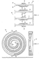
- FIGURE 4 is a schematic diagram of one example of a plurality of passageways formed in optical element 12 of FIGURE 1 . Illustrated are passageways 50 and 52. Passageway 50 has an outlet 54 and an inlet 56 for allowing the flow of refrigerant through passageway 50. Passageway 52 has an outlet 58 and an inlet 60 for allowing the flow of refrigerant through passageway 54. Although one example of passageways is illustrated, any suitable passageways may be utilized that results in a uniform enough temperature distribution for the desired purpose. By providing such a plurality of passageways, a relatively uniform temperature distribution may be achieved for components of structure 22 and allow cooling of structure 22 to a desired temperature.
- FIGURE 5 is a block diagram illustrating the cooling system 120 according to the teachings of the invention.
- System 120 includes many of the same elements of system 20 and are illustrated with similar corresponding reference numerals.
- system 120 includes a heat exchanger 144, a three-way valve 148 and a second three-way valve 150.
- Heat exchanger 144 may have a layer of insulation 146 wrapped around it.
- a pre-cooling loop is the loop connecting the points a-b-c-d-e-f; a boost loop is the loop connecting points a-b-c-d-h-i-j-e-f; and a low-temperature loop is the node connecting points a-b-g-i-j-e-f.
- the pre-cooling loop passes the cold refrigerant from heat exchanger 124 through the accumulator 126 and through pump 128 to three-way valve 148.
- Valve 148 is positioned to divert the flow to heat exchange system 142 and into heat exchanger 144. Heat exchanger 144 exchanges heat between a phase change material and the refrigerant in loop 130.
- the chilled refrigerant cools, solidifies, and then sub-cools the phase change material to a low temperature.
- a suitable phase change material is a paraffin.
- the phase change material may be tailored to melt at a pre-specified temperature. Refrigerant then passes to three-way valve 150 and returns to the heat-exchanger 124 through points e and f.
- three-way valve 150 Upon command of a controller, three-way valve 150 then diverts the flow of the refrigerant to structure 122, providing instant cooling capability to the system mass. The refrigerant then passes from structure 122 and returns exchanger 124 via points e and f. This cooling loop is known as the boost loop.
- a sensor may identify the point at which the minimum temperature is reached by the boost loop and use three-way valve 148 to divert the refrigerant flow from point c to point g, where it passes directly to the system mass for cooling to the lowest temperatures. The flow then passes through structure 122 to point j and on to heat exchanger 124 through points 3 and f, this is known as the low temperature loop.
- cooling system 120 allows precooling of a thermal mass associated with heat exchanger 144, which in turns allows more rapid cooling of structure 122 than would occur without the precooling. This provides the capability of using time periods in which heat exchanger 124 could not operate (such as when an associated airplane in on the runway, in the example of FIGURE 1 ), to nevertheless begin the cooling process, resulting in reaching the desired temperature of structure 122 earlier than would it would otherwise.
Landscapes
- Engineering & Computer Science (AREA)
- Physics & Mathematics (AREA)
- Mechanical Engineering (AREA)
- Thermal Sciences (AREA)
- General Engineering & Computer Science (AREA)
- Crystals, And After-Treatments Of Crystals (AREA)
Claims (10)
- Verfahren zum Bereitstellen einer Kühlung in einem Vorwärtsschauenden-Infrarot-Radarturm (10), aufweisend:fließen Lassen eines gesättigten Kühlmittels (46) durch eine Vielzahl von Durchgängen (50;52) in einem optischen Element (12) des Vorwärtsschauenden-Infrarot-Radarturms (10), während das Kühlmittel (46) bei einem im Wesentlichen konstanten Druck gehalten wird, wobei das optische Element (12) Infrarotstrahlung durch ein Fenster (16) empfängt unddie Infrarotenergie auf einen gewünschten Punkt zurück richtet und/oder fokussiert; undverdampfen Lassen zumindest eines Teils des Kühlmittels (46) bei einer im Wesentlichen konstanten Temperatur durch die Durchgänge (50;52) in dem optischen Element (12) in dem Vorwärtsschauenden-Infrarot-Radarturm (10),wobei die Vielzahl der Durchgänge (50;52) über das optische Element verteilt ist, um eine gleichmäßige Temperaturverteilung über das optische Element (12) bereitzustellen, ferner aufweisend daszirkulieren Lassen des Kühlmittels (46) in einer Schleife (a-b-c-d-h-i-j-e-f), die die Durchgänge (50;52) enthält, ferner aufweisendKühlen des Kühlmittels (46), bevor das Kühlmittel (46) durch die Durchgänge (50;52) fließen Gelassen wird, wobei das Kühlen des Kühlmittels (46) durch einen Wärmetauscher (144) in der Schleife (a-b-c-d-h-i-j-e-f) umfasst,wobei das Verfahrendas Weiterleiten des Kühlmittels (46), um in einer zweiten Schleife (a-b-g-i-j-e-f), die den Wärmetauscher (144) nicht enthält, zu fließen, nachdem das Kühlmittel (46) eine vorgegebene Temperatur erreicht hat, aufweist.
- Verfahren nach Anspruch 1, und ferner aufweisend kondensieren Lassen des verdampften Kühlmittels (46) in dem Wärmetauscher (24,124,144).
- Verfahren nach Anspruch 2, wobei der Wärmetauscher (24,124,144) zumindest ein thermoelektrisches Element (44) aufweist.
- Verfahren nach Anspruch 3, wobei das zumindest eine thermoelektrische Element (44) eine heiße Seite (48) und eine kalte Seite (50) aufweist, wobei das verdampfte Kühlmittel (46) beim Fließen auf der kalten Seite (50) kondensiert und Wärme an einen Luftstrom abgegeben wird, der an der heißen Seite (48) strömt.
- Verfahren nach irgendeinem der vorstehenden Ansprüche, wobei das Kühlmittel (46) bei seiner Sättigungstemperatur und seinem Sättigungsdruck gehalten wird.
- Verfahren nach irgendeinem der vorstehenden Ansprüche, wobei das fließen Lassen eines Kühlmittels (46) das fließen Lassen von R404A aufweist.
- Verfahren nach irgendeinem der vorstehenden Ansprüche, wobei das optische Element (12) in dem Vorwärtsschauenden-Infrarot-Radarturm (10) einen Stromkreislauf aufweist.
- Verfahren nach Anspruch 3 oder irgendeinem Anspruch, der direkt oder indirekt von Anspruch 2 abhängt, wobei der Wärmetauscher (24;124;14) einen nach dem umgekehrten Carnot'schen Kreisprozess arbeitenden Wärmetauscher umfasst.
- Verfahren nach Anspruch 3, und das ferner das Steuern der Leistung, die an das zumindest eine thermoelektrische Element (44) gegeben wird aufweist, um das optische Element (12) in dem Vorwärtsschauenden-Infrarot-Radarturm (10) bei einer gewünschten Temperatur zu halten.
- Verfahren nach Anspruch 9, und das ferner das Dissipieren von Hitze durch den Wärmetauscher (24;124;144) an eine Umgebung mit einer Temperatur, die größer ist als die gewünschte Temperatur, aufweist.
Applications Claiming Priority (2)
| Application Number | Priority Date | Filing Date | Title |
|---|---|---|---|
| US10/876,789 US8341965B2 (en) | 2004-06-24 | 2004-06-24 | Method and system for cooling |
| US876789 | 2004-06-24 |
Related Child Applications (1)
| Application Number | Title | Priority Date | Filing Date |
|---|---|---|---|
| EP10004208.4 Division-Into | 2010-04-21 |
Publications (3)
| Publication Number | Publication Date |
|---|---|
| EP1610077A2 EP1610077A2 (de) | 2005-12-28 |
| EP1610077A3 EP1610077A3 (de) | 2007-01-17 |
| EP1610077B1 true EP1610077B1 (de) | 2010-11-24 |
Family
ID=35045025
Family Applications (1)
| Application Number | Title | Priority Date | Filing Date |
|---|---|---|---|
| EP05253902A Expired - Lifetime EP1610077B1 (de) | 2004-06-24 | 2005-06-23 | Verfahren zum Kühlen |
Country Status (5)
| Country | Link |
|---|---|
| US (1) | US8341965B2 (de) |
| EP (1) | EP1610077B1 (de) |
| AT (1) | ATE489591T1 (de) |
| DE (1) | DE602005024892D1 (de) |
| ES (1) | ES2357010T3 (de) |
Cited By (1)
| Publication number | Priority date | Publication date | Assignee | Title |
|---|---|---|---|---|
| US7921655B2 (en) | 2007-09-21 | 2011-04-12 | Raytheon Company | Topping cycle for a sub-ambient cooling system |
Families Citing this family (26)
| Publication number | Priority date | Publication date | Assignee | Title |
|---|---|---|---|---|
| US7406839B2 (en) * | 2005-10-05 | 2008-08-05 | American Power Conversion Corporation | Sub-cooling unit for cooling system and method |
| US8672732B2 (en) | 2006-01-19 | 2014-03-18 | Schneider Electric It Corporation | Cooling system and method |
| US7365973B2 (en) | 2006-01-19 | 2008-04-29 | American Power Conversion Corporation | Cooling system and method |
| US8327656B2 (en) | 2006-08-15 | 2012-12-11 | American Power Conversion Corporation | Method and apparatus for cooling |
| US9568206B2 (en) | 2006-08-15 | 2017-02-14 | Schneider Electric It Corporation | Method and apparatus for cooling |
| US8322155B2 (en) | 2006-08-15 | 2012-12-04 | American Power Conversion Corporation | Method and apparatus for cooling |
| US7861543B2 (en) | 2006-11-03 | 2011-01-04 | American Power Conversion Corporation | Water carryover avoidance method |
| US7681404B2 (en) | 2006-12-18 | 2010-03-23 | American Power Conversion Corporation | Modular ice storage for uninterruptible chilled water |
| US8425287B2 (en) | 2007-01-23 | 2013-04-23 | Schneider Electric It Corporation | In-row air containment and cooling system and method |
| AU2008255030B2 (en) | 2007-05-15 | 2014-02-20 | Schneider Electric It Corporation | Methods and systems for managing facility power and cooling |
| US8701746B2 (en) | 2008-03-13 | 2014-04-22 | Schneider Electric It Corporation | Optically detected liquid depth information in a climate control unit |
| US8219362B2 (en) | 2009-05-08 | 2012-07-10 | American Power Conversion Corporation | System and method for arranging equipment in a data center |
| US9513569B2 (en) * | 2010-03-18 | 2016-12-06 | ETH Zürich | Optical collector for collecting extreme ultraviolet radiation, method for operating such an optical collector, and EUV source with such a collector |
| US8688413B2 (en) | 2010-12-30 | 2014-04-01 | Christopher M. Healey | System and method for sequential placement of cooling resources within data center layouts |
| FR2973311B1 (fr) * | 2011-03-31 | 2017-09-01 | Valeo Systemes Thermiques | Dispositif et procede de degivrage / desembuage pour vehicule a propulsion electrique |
| US9830410B2 (en) | 2011-12-22 | 2017-11-28 | Schneider Electric It Corporation | System and method for prediction of temperature values in an electronics system |
| WO2013095516A1 (en) | 2011-12-22 | 2013-06-27 | Schneider Electric It Corporation | Analysis of effect of transient events on temperature in a data center |
| US10174977B2 (en) | 2012-11-21 | 2019-01-08 | Vertiv Corporation | Apparatus and method for subcooling control based on superheat setpoint control |
| US20160120059A1 (en) | 2014-10-27 | 2016-04-28 | Ebullient, Llc | Two-phase cooling system |
| AT516611B1 (de) * | 2015-06-23 | 2016-07-15 | Avl List Gmbh | Temperiereinheit für ein gasförmiges oder flüssiges Medium |
| US20170283074A1 (en) * | 2016-03-31 | 2017-10-05 | Hamilton Sundstrand Corporation | Aircraft air conditioning system including a thermoelectric device |
| US10775110B2 (en) | 2018-04-12 | 2020-09-15 | Rolls-Royce North American Technologies, Inc. | Tight temperature control at a thermal load with a two phase pumped loop, optionally augmented with a vapor compression cycle |
| US11150025B2 (en) | 2018-05-10 | 2021-10-19 | Raytheon Company | Heat exchangers for multi-axis gimbal pointing or targeting systems |
| US11273925B1 (en) | 2020-10-14 | 2022-03-15 | Rolls-Royce North American Technologies Inc. | Thermal management system and method for cooling a hybrid electric aircraft propulsion system |
| WO2022232624A1 (en) * | 2021-04-29 | 2022-11-03 | Vertiv Corporation | Pumped refrigerant system and associated method for cold starting a pumped refrigerant system |
| US11988427B2 (en) | 2021-04-29 | 2024-05-21 | Vertiv Corporation | Refrigerant cold start system |
Family Cites Families (67)
| Publication number | Priority date | Publication date | Assignee | Title |
|---|---|---|---|---|
| US2321964A (en) | 1941-08-08 | 1943-06-15 | York Ice Machinery Corp | Purge system for refrigerative circuits |
| BE604735A (fr) | 1960-06-08 | 1961-12-07 | Geigy Ag J R | Composés azoïques cycliques et leur préparation. |
| US3131548A (en) | 1962-11-01 | 1964-05-05 | Worthington Corp | Refrigeration purge control |
| US3174540A (en) | 1963-09-03 | 1965-03-23 | Gen Electric | Vaporization cooling of electrical apparatus |
| US3371298A (en) | 1966-02-03 | 1968-02-27 | Westinghouse Electric Corp | Cooling system for electrical apparatus |
| US3609991A (en) | 1969-10-13 | 1971-10-05 | Ibm | Cooling system having thermally induced circulation |
| US3586101A (en) | 1969-12-22 | 1971-06-22 | Ibm | Cooling system for data processing equipment |
| US3774677A (en) | 1971-02-26 | 1973-11-27 | Ibm | Cooling system providing spray type condensation |
| US3756903A (en) | 1971-06-15 | 1973-09-04 | Wakefield Eng Inc | Closed loop system for maintaining constant temperature |
| US3731992A (en) * | 1972-04-06 | 1973-05-08 | States Of Air Force | Spiral grooved liquid cooled laser mirror |
| US5333677A (en) | 1974-04-02 | 1994-08-02 | Stephen Molivadas | Evacuated two-phase head-transfer systems |
| US3989102A (en) | 1974-10-18 | 1976-11-02 | General Electric Company | Cooling liquid de-gassing system |
| US4019098A (en) | 1974-11-25 | 1977-04-19 | Sundstrand Corporation | Heat pipe cooling system for electronic devices |
| US4003213A (en) | 1975-11-28 | 1977-01-18 | Robert Bruce Cox | Triple-point heat pump |
| JPS55118561A (en) | 1979-03-05 | 1980-09-11 | Hitachi Ltd | Constant pressure type boiling cooler |
| US4511376A (en) | 1980-04-07 | 1985-04-16 | Coury Glenn E | Method of separating a noncondensable gas from a condensable vapor |
| US4357077A (en) * | 1980-10-14 | 1982-11-02 | Yevick George J | High powered laser window-mirror |
| US4381817A (en) | 1981-04-27 | 1983-05-03 | Foster Wheeler Energy Corporation | Wet/dry steam condenser |
| US4495988A (en) | 1982-04-09 | 1985-01-29 | The Charles Stark Draper Laboratory, Inc. | Controlled heat exchanger system |
| US4569591A (en) * | 1983-03-07 | 1986-02-11 | Texas Instruments Incorporated | Laser boresight alignment mechanism for integrated laser/FLIR rangefinder |
| US4561775A (en) * | 1983-03-07 | 1985-12-31 | Texas Instruments Incorporated | Thermally integrated laser/FLIR rangefinder |
| US4733961A (en) * | 1983-03-07 | 1988-03-29 | Texas Instruments Incorporated | Amplifier for integrated laser/FLIR rangefinder |
| FR2602035B1 (fr) | 1986-04-23 | 1990-05-25 | Michel Bosteels | Procede et installation de transfert de chaleur entre un fluide et un organe a refroidir ou rechauffer, par mise en depression du fluide par rapport a la pression atmospherique |
| EP0251836B1 (de) | 1986-05-30 | 1991-07-17 | Digital Equipment Corporation | Vollständiges Wärmerohr-Modul |
| US4794984A (en) | 1986-11-10 | 1989-01-03 | Lin Pang Yien | Arrangement for increasing heat transfer coefficient between a heating surface and a boiling liquid |
| US4998181A (en) | 1987-12-15 | 1991-03-05 | Texas Instruments Incorporated | Coldplate for cooling electronic equipment |
| US4851856A (en) | 1988-02-16 | 1989-07-25 | Westinghouse Electric Corp. | Flexible diaphragm cooling device for microwave antennas |
| JPH06100408B2 (ja) | 1988-09-09 | 1994-12-12 | 日本電気株式会社 | 冷却装置 |
| US4938280A (en) | 1988-11-07 | 1990-07-03 | Clark William E | Liquid-cooled, flat plate heat exchanger |
| US4993487A (en) | 1989-03-29 | 1991-02-19 | Sundstrand Corporation | Spiral heat exchanger |
| DE4118196C2 (de) | 1990-06-29 | 1995-07-06 | Erno Raumfahrttechnik Gmbh | Verdampfungswärmetauscher |
| US5168919A (en) | 1990-06-29 | 1992-12-08 | Digital Equipment Corporation | Air cooled heat exchanger for multi-chip assemblies |
| US5128689A (en) | 1990-09-20 | 1992-07-07 | Hughes Aircraft Company | Ehf array antenna backplate including radiating modules, cavities, and distributor supported thereon |
| CA2053055C (en) | 1990-10-11 | 1997-02-25 | Tsukasa Mizuno | Liquid cooling system for lsi packages |
| US5148859A (en) | 1991-02-11 | 1992-09-22 | General Motors Corporation | Air/liquid heat exchanger |
| US5209291A (en) * | 1991-06-28 | 1993-05-11 | Hughes Aircraft Company | Cooling apparatus for optical devices |
| US5276319A (en) * | 1992-04-21 | 1994-01-04 | The United States Of America As Represented By The United States Secretary Of The Navy | Method and device for improved IR detection with compensations for individual detector response |
| US5239443A (en) | 1992-04-23 | 1993-08-24 | International Business Machines Corporation | Blind hole cold plate cooling system |
| US5501082A (en) | 1992-06-16 | 1996-03-26 | Hitachi Building Equipment Engineering Co., Ltd. | Refrigeration purge and/or recovery apparatus |
| US5261246A (en) | 1992-10-07 | 1993-11-16 | Blackmon John G | Apparatus and method for purging a refrigeration system |
| US5317395A (en) * | 1993-03-31 | 1994-05-31 | The United States Of America As Represented By The Secretary Of The Army | Focal plane array dual processing system and technique |
| US5493305A (en) | 1993-04-15 | 1996-02-20 | Hughes Aircraft Company | Small manufacturable array lattice layers |
| US5361587A (en) * | 1993-05-25 | 1994-11-08 | Paul Georgeades | Vapor-compression-cycle refrigeration system having a thermoelectric condenser |
| US5515690A (en) | 1995-02-13 | 1996-05-14 | Carolina Products, Inc. | Automatic purge supplement after chamber with adsorbent |
| US5960861A (en) | 1995-04-05 | 1999-10-05 | Raytheon Company | Cold plate design for thermal management of phase array-radar systems |
| US5648868A (en) * | 1995-05-12 | 1997-07-15 | The United States Of America As Represented By The Secretary Of The Army | Second generation FLIR NV-81 |
| US5943211A (en) | 1997-04-18 | 1999-08-24 | Raytheon Company | Heat spreader system for cooling heat generating components |
| US5841564A (en) | 1996-12-31 | 1998-11-24 | Motorola, Inc. | Apparatus for communication by an electronic device and method for communicating between electronic devices |
| US5806322A (en) | 1997-04-07 | 1998-09-15 | York International | Refrigerant recovery method |
| US5818692A (en) | 1997-05-30 | 1998-10-06 | Motorola, Inc. | Apparatus and method for cooling an electrical component |
| US6055154A (en) | 1998-07-17 | 2000-04-25 | Lucent Technologies Inc. | In-board chip cooling system |
| US6018192A (en) | 1998-07-30 | 2000-01-25 | Motorola, Inc. | Electronic device with a thermal control capability |
| EP1681342B1 (de) * | 1999-03-05 | 2011-02-16 | Idemitsu Kosan Co., Ltd. | Ölzusammensetzung für Kühlmaschine |
| SE9901501L (sv) | 1999-04-27 | 2000-06-26 | Abb Ab | Anordning vid elektriska apparater med en kylinrättning samt förfarande för undvikande av förlust av kylmedium |
| US6297775B1 (en) | 1999-09-16 | 2001-10-02 | Raytheon Company | Compact phased array antenna system, and a method of operating same |
| US6519955B2 (en) | 2000-04-04 | 2003-02-18 | Thermal Form & Function | Pumped liquid cooling system using a phase change refrigerant |
| US6292364B1 (en) | 2000-04-28 | 2001-09-18 | Raytheon Company | Liquid spray cooled module |
| US7017651B1 (en) | 2000-09-13 | 2006-03-28 | Raytheon Company | Method and apparatus for temperature gradient control in an electronic system |
| US6498725B2 (en) | 2001-05-01 | 2002-12-24 | Mainstream Engineering Corporation | Method and two-phase spray cooling apparatus |
| JP3946018B2 (ja) | 2001-09-18 | 2007-07-18 | 株式会社日立製作所 | 液冷却式回路装置 |
| US20040023419A1 (en) * | 2001-09-24 | 2004-02-05 | Extraction Systems, Inc | System and method for monitoring contamination |
| US6825978B2 (en) * | 2002-04-04 | 2004-11-30 | Hypervision, Inc. | High sensitivity thermal radiation detection with an emission microscope with room temperature optics |
| US6705089B2 (en) | 2002-04-04 | 2004-03-16 | International Business Machines Corporation | Two stage cooling system employing thermoelectric modules |
| US6972950B1 (en) * | 2002-06-06 | 2005-12-06 | Raytheon Company | Method and apparatus for cooling a portable computer |
| US7000691B1 (en) | 2002-07-11 | 2006-02-21 | Raytheon Company | Method and apparatus for cooling with coolant at a subambient pressure |
| US20040065850A1 (en) * | 2002-10-02 | 2004-04-08 | Kane Todd A. | Thermal imaging identification signage |
| US6957550B2 (en) * | 2003-05-19 | 2005-10-25 | Raytheon Company | Method and apparatus for extracting non-condensable gases in a cooling system |
-
2004
- 2004-06-24 US US10/876,789 patent/US8341965B2/en active Active
-
2005
- 2005-06-23 EP EP05253902A patent/EP1610077B1/de not_active Expired - Lifetime
- 2005-06-23 AT AT05253902T patent/ATE489591T1/de not_active IP Right Cessation
- 2005-06-23 ES ES05253902T patent/ES2357010T3/es not_active Expired - Lifetime
- 2005-06-23 DE DE602005024892T patent/DE602005024892D1/de not_active Expired - Lifetime
Cited By (1)
| Publication number | Priority date | Publication date | Assignee | Title |
|---|---|---|---|---|
| US7921655B2 (en) | 2007-09-21 | 2011-04-12 | Raytheon Company | Topping cycle for a sub-ambient cooling system |
Also Published As
| Publication number | Publication date |
|---|---|
| US20050284153A1 (en) | 2005-12-29 |
| EP1610077A3 (de) | 2007-01-17 |
| EP1610077A2 (de) | 2005-12-28 |
| ATE489591T1 (de) | 2010-12-15 |
| DE602005024892D1 (de) | 2011-01-05 |
| US8341965B2 (en) | 2013-01-01 |
| ES2357010T3 (es) | 2011-04-15 |
Similar Documents
| Publication | Publication Date | Title |
|---|---|---|
| EP1610077B1 (de) | Verfahren zum Kühlen | |
| US11035621B2 (en) | Electronics cooling with multi-phase heat exchange and heat spreader | |
| US7000691B1 (en) | Method and apparatus for cooling with coolant at a subambient pressure | |
| US20200113085A1 (en) | System and method for recovering and upgrading waste heat while cooling devices | |
| US10548241B2 (en) | Two-phase cooling with ambient cooled condensor | |
| EP1143778B1 (de) | Einzupumpendes Flüssigkeitskühlsystem mit Phasenumwandlungskühlung | |
| US7254957B2 (en) | Method and apparatus for cooling with coolant at a subambient pressure | |
| EP2203696B1 (de) | Kühlsystem | |
| US20090158757A1 (en) | System and method for controlling the cooling of variable heat loads in heat generating devices | |
| KR102517065B1 (ko) | 냉각발생장치 | |
| CN103538722B (zh) | 冷却单元的功率电子器件的热耗散 | |
| US11092376B2 (en) | Refrigeration device comprising multiple storage chambers | |
| US5398519A (en) | Thermal control system | |
| CN115042977A (zh) | 应用低温消耗性热沉的兆瓦级热负载机载热管理系统 | |
| US20180261748A1 (en) | Thermoelectric heat pump cascade using multiple printed circuit boards with thermoelectric modules | |
| JP7174502B2 (ja) | 多段冷凍サイクルを用いた温度調節装置及びそれを用いた温度調節方法 | |
| US9899789B2 (en) | Thermal management systems | |
| CN108458509B (zh) | 一种高温度稳定性冷媒冷却系统 | |
| JP2008502878A (ja) | 準大気冷却サイクル | |
| van Es et al. | AMS02 tracker thermal control cooling system commissioning and operational results | |
| EP1524190B1 (de) | Triebwerkkühlungssystem | |
| Scaringe | A compact thermal control system for aircraft avionics pod cooling | |
| JP2009539246A (ja) | 電子部品用温度管理 | |
| Singh et al. | Innovative multi-environment, multimode thermal control system | |
| WO2026035591A1 (en) | Immersion cooling systems including vapor-compression cooling loop |
Legal Events
| Date | Code | Title | Description |
|---|---|---|---|
| PUAI | Public reference made under article 153(3) epc to a published international application that has entered the european phase |
Free format text: ORIGINAL CODE: 0009012 |
|
| AK | Designated contracting states |
Kind code of ref document: A2 Designated state(s): AT BE BG CH CY CZ DE DK EE ES FI FR GB GR HU IE IS IT LI LT LU MC NL PL PT RO SE SI SK TR |
|
| AX | Request for extension of the european patent |
Extension state: AL BA HR LV MK YU |
|
| PUAL | Search report despatched |
Free format text: ORIGINAL CODE: 0009013 |
|
| AK | Designated contracting states |
Kind code of ref document: A3 Designated state(s): AT BE BG CH CY CZ DE DK EE ES FI FR GB GR HU IE IS IT LI LT LU MC NL PL PT RO SE SI SK TR |
|
| AX | Request for extension of the european patent |
Extension state: AL BA HR LV MK YU |
|
| 17P | Request for examination filed |
Effective date: 20070707 |
|
| AKX | Designation fees paid |
Designated state(s): AT BE BG CH CY CZ DE DK EE ES FI FR GB GR HU IE IS IT LI LT LU MC NL PL PT RO SE SI SK TR |
|
| 17Q | First examination report despatched |
Effective date: 20071128 |
|
| GRAP | Despatch of communication of intention to grant a patent |
Free format text: ORIGINAL CODE: EPIDOSNIGR1 |
|
| RTI1 | Title (correction) |
Free format text: A METHOD FOR COOLING |
|
| GRAS | Grant fee paid |
Free format text: ORIGINAL CODE: EPIDOSNIGR3 |
|
| GRAA | (expected) grant |
Free format text: ORIGINAL CODE: 0009210 |
|
| AK | Designated contracting states |
Kind code of ref document: B1 Designated state(s): AT BE BG CH CY CZ DE DK EE ES FI FR GB GR HU IE IS IT LI LT LU MC NL PL PT RO SE SI SK TR |
|
| REG | Reference to a national code |
Ref country code: GB Ref legal event code: FG4D |
|
| REG | Reference to a national code |
Ref country code: CH Ref legal event code: EP |
|
| REG | Reference to a national code |
Ref country code: IE Ref legal event code: FG4D |
|
| REF | Corresponds to: |
Ref document number: 602005024892 Country of ref document: DE Date of ref document: 20110105 Kind code of ref document: P |
|
| REG | Reference to a national code |
Ref country code: NL Ref legal event code: VDEP Effective date: 20101124 |
|
| REG | Reference to a national code |
Ref country code: ES Ref legal event code: FG2A Ref document number: 2357010 Country of ref document: ES Kind code of ref document: T3 Effective date: 20110415 |
|
| LTIE | Lt: invalidation of european patent or patent extension |
Effective date: 20101124 |
|
| PG25 | Lapsed in a contracting state [announced via postgrant information from national office to epo] |
Ref country code: LT Free format text: LAPSE BECAUSE OF FAILURE TO SUBMIT A TRANSLATION OF THE DESCRIPTION OR TO PAY THE FEE WITHIN THE PRESCRIBED TIME-LIMIT Effective date: 20101124 |
|
| PG25 | Lapsed in a contracting state [announced via postgrant information from national office to epo] |
Ref country code: SI Free format text: LAPSE BECAUSE OF FAILURE TO SUBMIT A TRANSLATION OF THE DESCRIPTION OR TO PAY THE FEE WITHIN THE PRESCRIBED TIME-LIMIT Effective date: 20101124 Ref country code: SE Free format text: LAPSE BECAUSE OF FAILURE TO SUBMIT A TRANSLATION OF THE DESCRIPTION OR TO PAY THE FEE WITHIN THE PRESCRIBED TIME-LIMIT Effective date: 20101124 Ref country code: PT Free format text: LAPSE BECAUSE OF FAILURE TO SUBMIT A TRANSLATION OF THE DESCRIPTION OR TO PAY THE FEE WITHIN THE PRESCRIBED TIME-LIMIT Effective date: 20110324 Ref country code: AT Free format text: LAPSE BECAUSE OF FAILURE TO SUBMIT A TRANSLATION OF THE DESCRIPTION OR TO PAY THE FEE WITHIN THE PRESCRIBED TIME-LIMIT Effective date: 20101124 Ref country code: IS Free format text: LAPSE BECAUSE OF FAILURE TO SUBMIT A TRANSLATION OF THE DESCRIPTION OR TO PAY THE FEE WITHIN THE PRESCRIBED TIME-LIMIT Effective date: 20110324 Ref country code: NL Free format text: LAPSE BECAUSE OF FAILURE TO SUBMIT A TRANSLATION OF THE DESCRIPTION OR TO PAY THE FEE WITHIN THE PRESCRIBED TIME-LIMIT Effective date: 20101124 Ref country code: BG Free format text: LAPSE BECAUSE OF FAILURE TO SUBMIT A TRANSLATION OF THE DESCRIPTION OR TO PAY THE FEE WITHIN THE PRESCRIBED TIME-LIMIT Effective date: 20110224 Ref country code: FI Free format text: LAPSE BECAUSE OF FAILURE TO SUBMIT A TRANSLATION OF THE DESCRIPTION OR TO PAY THE FEE WITHIN THE PRESCRIBED TIME-LIMIT Effective date: 20101124 Ref country code: CY Free format text: LAPSE BECAUSE OF FAILURE TO SUBMIT A TRANSLATION OF THE DESCRIPTION OR TO PAY THE FEE WITHIN THE PRESCRIBED TIME-LIMIT Effective date: 20101124 |
|
| PG25 | Lapsed in a contracting state [announced via postgrant information from national office to epo] |
Ref country code: GR Free format text: LAPSE BECAUSE OF FAILURE TO SUBMIT A TRANSLATION OF THE DESCRIPTION OR TO PAY THE FEE WITHIN THE PRESCRIBED TIME-LIMIT Effective date: 20110225 |
|
| PG25 | Lapsed in a contracting state [announced via postgrant information from national office to epo] |
Ref country code: EE Free format text: LAPSE BECAUSE OF FAILURE TO SUBMIT A TRANSLATION OF THE DESCRIPTION OR TO PAY THE FEE WITHIN THE PRESCRIBED TIME-LIMIT Effective date: 20101124 Ref country code: CZ Free format text: LAPSE BECAUSE OF FAILURE TO SUBMIT A TRANSLATION OF THE DESCRIPTION OR TO PAY THE FEE WITHIN THE PRESCRIBED TIME-LIMIT Effective date: 20101124 Ref country code: BE Free format text: LAPSE BECAUSE OF FAILURE TO SUBMIT A TRANSLATION OF THE DESCRIPTION OR TO PAY THE FEE WITHIN THE PRESCRIBED TIME-LIMIT Effective date: 20101124 |
|
| PG25 | Lapsed in a contracting state [announced via postgrant information from national office to epo] |
Ref country code: SK Free format text: LAPSE BECAUSE OF FAILURE TO SUBMIT A TRANSLATION OF THE DESCRIPTION OR TO PAY THE FEE WITHIN THE PRESCRIBED TIME-LIMIT Effective date: 20101124 Ref country code: RO Free format text: LAPSE BECAUSE OF FAILURE TO SUBMIT A TRANSLATION OF THE DESCRIPTION OR TO PAY THE FEE WITHIN THE PRESCRIBED TIME-LIMIT Effective date: 20101124 Ref country code: DK Free format text: LAPSE BECAUSE OF FAILURE TO SUBMIT A TRANSLATION OF THE DESCRIPTION OR TO PAY THE FEE WITHIN THE PRESCRIBED TIME-LIMIT Effective date: 20101124 Ref country code: PL Free format text: LAPSE BECAUSE OF FAILURE TO SUBMIT A TRANSLATION OF THE DESCRIPTION OR TO PAY THE FEE WITHIN THE PRESCRIBED TIME-LIMIT Effective date: 20101124 |
|
| PLBE | No opposition filed within time limit |
Free format text: ORIGINAL CODE: 0009261 |
|
| STAA | Information on the status of an ep patent application or granted ep patent |
Free format text: STATUS: NO OPPOSITION FILED WITHIN TIME LIMIT |
|
| 26N | No opposition filed |
Effective date: 20110825 |
|
| REG | Reference to a national code |
Ref country code: DE Ref legal event code: R097 Ref document number: 602005024892 Country of ref document: DE Effective date: 20110825 |
|
| REG | Reference to a national code |
Ref country code: CH Ref legal event code: PL |
|
| REG | Reference to a national code |
Ref country code: IE Ref legal event code: MM4A |
|
| PG25 | Lapsed in a contracting state [announced via postgrant information from national office to epo] |
Ref country code: LI Free format text: LAPSE BECAUSE OF NON-PAYMENT OF DUE FEES Effective date: 20110630 Ref country code: IE Free format text: LAPSE BECAUSE OF NON-PAYMENT OF DUE FEES Effective date: 20110623 Ref country code: CH Free format text: LAPSE BECAUSE OF NON-PAYMENT OF DUE FEES Effective date: 20110630 |
|
| PG25 | Lapsed in a contracting state [announced via postgrant information from national office to epo] |
Ref country code: MC Free format text: LAPSE BECAUSE OF NON-PAYMENT OF DUE FEES Effective date: 20110630 |
|
| PG25 | Lapsed in a contracting state [announced via postgrant information from national office to epo] |
Ref country code: LU Free format text: LAPSE BECAUSE OF NON-PAYMENT OF DUE FEES Effective date: 20110623 |
|
| PG25 | Lapsed in a contracting state [announced via postgrant information from national office to epo] |
Ref country code: TR Free format text: LAPSE BECAUSE OF FAILURE TO SUBMIT A TRANSLATION OF THE DESCRIPTION OR TO PAY THE FEE WITHIN THE PRESCRIBED TIME-LIMIT Effective date: 20101124 |
|
| PG25 | Lapsed in a contracting state [announced via postgrant information from national office to epo] |
Ref country code: HU Free format text: LAPSE BECAUSE OF FAILURE TO SUBMIT A TRANSLATION OF THE DESCRIPTION OR TO PAY THE FEE WITHIN THE PRESCRIBED TIME-LIMIT Effective date: 20101124 |
|
| PGFP | Annual fee paid to national office [announced via postgrant information from national office to epo] |
Ref country code: GB Payment date: 20140618 Year of fee payment: 10 |
|
| PGFP | Annual fee paid to national office [announced via postgrant information from national office to epo] |
Ref country code: IT Payment date: 20140610 Year of fee payment: 10 Ref country code: ES Payment date: 20140513 Year of fee payment: 10 Ref country code: DE Payment date: 20140618 Year of fee payment: 10 |
|
| PGFP | Annual fee paid to national office [announced via postgrant information from national office to epo] |
Ref country code: FR Payment date: 20140609 Year of fee payment: 10 |
|
| REG | Reference to a national code |
Ref country code: DE Ref legal event code: R119 Ref document number: 602005024892 Country of ref document: DE |
|
| PG25 | Lapsed in a contracting state [announced via postgrant information from national office to epo] |
Ref country code: IT Free format text: LAPSE BECAUSE OF NON-PAYMENT OF DUE FEES Effective date: 20150623 |
|
| GBPC | Gb: european patent ceased through non-payment of renewal fee |
Effective date: 20150623 |
|
| REG | Reference to a national code |
Ref country code: FR Ref legal event code: ST Effective date: 20160229 |
|
| PG25 | Lapsed in a contracting state [announced via postgrant information from national office to epo] |
Ref country code: DE Free format text: LAPSE BECAUSE OF NON-PAYMENT OF DUE FEES Effective date: 20160101 Ref country code: GB Free format text: LAPSE BECAUSE OF NON-PAYMENT OF DUE FEES Effective date: 20150623 |
|
| PG25 | Lapsed in a contracting state [announced via postgrant information from national office to epo] |
Ref country code: FR Free format text: LAPSE BECAUSE OF NON-PAYMENT OF DUE FEES Effective date: 20150630 |
|
| REG | Reference to a national code |
Ref country code: ES Ref legal event code: FD2A Effective date: 20160728 |
|
| PG25 | Lapsed in a contracting state [announced via postgrant information from national office to epo] |
Ref country code: ES Free format text: LAPSE BECAUSE OF NON-PAYMENT OF DUE FEES Effective date: 20150624 |