EP3553363B1 - Kupplungselement und kupplungsvorrichtung mit solchem kupplungselement - Google Patents
Kupplungselement und kupplungsvorrichtung mit solchem kupplungselement Download PDFInfo
- Publication number
- EP3553363B1 EP3553363B1 EP19168583.3A EP19168583A EP3553363B1 EP 3553363 B1 EP3553363 B1 EP 3553363B1 EP 19168583 A EP19168583 A EP 19168583A EP 3553363 B1 EP3553363 B1 EP 3553363B1
- Authority
- EP
- European Patent Office
- Prior art keywords
- valve
- plunger
- main valve
- coupling element
- spring
- Prior art date
- Legal status (The legal status is an assumption and is not a legal conclusion. Google has not performed a legal analysis and makes no representation as to the accuracy of the status listed.)
- Active
Links
Images


Classifications
-
- F—MECHANICAL ENGINEERING; LIGHTING; HEATING; WEAPONS; BLASTING
- F16—ENGINEERING ELEMENTS AND UNITS; GENERAL MEASURES FOR PRODUCING AND MAINTAINING EFFECTIVE FUNCTIONING OF MACHINES OR INSTALLATIONS; THERMAL INSULATION IN GENERAL
- F16L—PIPES; JOINTS OR FITTINGS FOR PIPES; SUPPORTS FOR PIPES, CABLES OR PROTECTIVE TUBING; MEANS FOR THERMAL INSULATION IN GENERAL
- F16L29/00—Joints with fluid cut-off means
- F16L29/04—Joints with fluid cut-off means with a cut-off device in each of the two pipe ends, the cut-off devices being automatically opened when the coupling is applied
-
- F—MECHANICAL ENGINEERING; LIGHTING; HEATING; WEAPONS; BLASTING
- F16—ENGINEERING ELEMENTS AND UNITS; GENERAL MEASURES FOR PRODUCING AND MAINTAINING EFFECTIVE FUNCTIONING OF MACHINES OR INSTALLATIONS; THERMAL INSULATION IN GENERAL
- F16L—PIPES; JOINTS OR FITTINGS FOR PIPES; SUPPORTS FOR PIPES, CABLES OR PROTECTIVE TUBING; MEANS FOR THERMAL INSULATION IN GENERAL
- F16L37/00—Couplings of the quick-acting type
- F16L37/22—Couplings of the quick-acting type in which the connection is maintained by means of balls, rollers or helical springs under radial pressure between the parts
- F16L37/23—Couplings of the quick-acting type in which the connection is maintained by means of balls, rollers or helical springs under radial pressure between the parts by means of balls
-
- F—MECHANICAL ENGINEERING; LIGHTING; HEATING; WEAPONS; BLASTING
- F16—ENGINEERING ELEMENTS AND UNITS; GENERAL MEASURES FOR PRODUCING AND MAINTAINING EFFECTIVE FUNCTIONING OF MACHINES OR INSTALLATIONS; THERMAL INSULATION IN GENERAL
- F16L—PIPES; JOINTS OR FITTINGS FOR PIPES; SUPPORTS FOR PIPES, CABLES OR PROTECTIVE TUBING; MEANS FOR THERMAL INSULATION IN GENERAL
- F16L37/00—Couplings of the quick-acting type
- F16L37/28—Couplings of the quick-acting type with fluid cut-off means
- F16L37/30—Couplings of the quick-acting type with fluid cut-off means with fluid cut-off means in each of two pipe-end fittings
- F16L37/32—Couplings of the quick-acting type with fluid cut-off means with fluid cut-off means in each of two pipe-end fittings at least one of two lift valves being opened automatically when the coupling is applied
- F16L37/33—Couplings of the quick-acting type with fluid cut-off means with fluid cut-off means in each of two pipe-end fittings at least one of two lift valves being opened automatically when the coupling is applied the lift valves being of the ball type
-
- F—MECHANICAL ENGINEERING; LIGHTING; HEATING; WEAPONS; BLASTING
- F16—ENGINEERING ELEMENTS AND UNITS; GENERAL MEASURES FOR PRODUCING AND MAINTAINING EFFECTIVE FUNCTIONING OF MACHINES OR INSTALLATIONS; THERMAL INSULATION IN GENERAL
- F16L—PIPES; JOINTS OR FITTINGS FOR PIPES; SUPPORTS FOR PIPES, CABLES OR PROTECTIVE TUBING; MEANS FOR THERMAL INSULATION IN GENERAL
- F16L37/00—Couplings of the quick-acting type
- F16L37/28—Couplings of the quick-acting type with fluid cut-off means
- F16L37/30—Couplings of the quick-acting type with fluid cut-off means with fluid cut-off means in each of two pipe-end fittings
- F16L37/32—Couplings of the quick-acting type with fluid cut-off means with fluid cut-off means in each of two pipe-end fittings at least one of two lift valves being opened automatically when the coupling is applied
- F16L37/34—Couplings of the quick-acting type with fluid cut-off means with fluid cut-off means in each of two pipe-end fittings at least one of two lift valves being opened automatically when the coupling is applied at least one of the lift valves being of the sleeve type, i.e. a sleeve being telescoped over an inner cylindrical wall
-
- F—MECHANICAL ENGINEERING; LIGHTING; HEATING; WEAPONS; BLASTING
- F16—ENGINEERING ELEMENTS AND UNITS; GENERAL MEASURES FOR PRODUCING AND MAINTAINING EFFECTIVE FUNCTIONING OF MACHINES OR INSTALLATIONS; THERMAL INSULATION IN GENERAL
- F16L—PIPES; JOINTS OR FITTINGS FOR PIPES; SUPPORTS FOR PIPES, CABLES OR PROTECTIVE TUBING; MEANS FOR THERMAL INSULATION IN GENERAL
- F16L37/00—Couplings of the quick-acting type
- F16L37/28—Couplings of the quick-acting type with fluid cut-off means
- F16L37/30—Couplings of the quick-acting type with fluid cut-off means with fluid cut-off means in each of two pipe-end fittings
- F16L37/36—Couplings of the quick-acting type with fluid cut-off means with fluid cut-off means in each of two pipe-end fittings with two lift valves being actuated to initiate the flow through the coupling after the two coupling parts are locked against withdrawal
-
- F—MECHANICAL ENGINEERING; LIGHTING; HEATING; WEAPONS; BLASTING
- F16—ENGINEERING ELEMENTS AND UNITS; GENERAL MEASURES FOR PRODUCING AND MAINTAINING EFFECTIVE FUNCTIONING OF MACHINES OR INSTALLATIONS; THERMAL INSULATION IN GENERAL
- F16L—PIPES; JOINTS OR FITTINGS FOR PIPES; SUPPORTS FOR PIPES, CABLES OR PROTECTIVE TUBING; MEANS FOR THERMAL INSULATION IN GENERAL
- F16L37/00—Couplings of the quick-acting type
- F16L37/28—Couplings of the quick-acting type with fluid cut-off means
- F16L37/38—Couplings of the quick-acting type with fluid cut-off means with fluid cut-off means in only one of two pipe-end fittings
- F16L37/40—Couplings of the quick-acting type with fluid cut-off means with fluid cut-off means in only one of two pipe-end fittings with a lift valve being opened automatically when the coupling is applied
- F16L37/407—Couplings of the quick-acting type with fluid cut-off means with fluid cut-off means in only one of two pipe-end fittings with a lift valve being opened automatically when the coupling is applied the lift valve being of the ball type
-
- Y—GENERAL TAGGING OF NEW TECHNOLOGICAL DEVELOPMENTS; GENERAL TAGGING OF CROSS-SECTIONAL TECHNOLOGIES SPANNING OVER SEVERAL SECTIONS OF THE IPC; TECHNICAL SUBJECTS COVERED BY FORMER USPC CROSS-REFERENCE ART COLLECTIONS [XRACs] AND DIGESTS
- Y10—TECHNICAL SUBJECTS COVERED BY FORMER USPC
- Y10T—TECHNICAL SUBJECTS COVERED BY FORMER US CLASSIFICATION
- Y10T137/00—Fluid handling
- Y10T137/8593—Systems
- Y10T137/87917—Flow path with serial valves and/or closures
- Y10T137/87925—Separable flow path section, valve or closure in each
- Y10T137/87941—Each valve and/or closure operated by coupling motion
- Y10T137/87949—Linear motion of flow path sections operates both
- Y10T137/87957—Valves actuate each other
Definitions
- the invention relates to a connector element as well as a connector comprising such a connector element.
- connection elements make it possible to easily and quickly ensure a sealed connection for the transport of a fluid, in particular a pressurized fluid.
- Two connecting elements of complementary type for example of male type and of female type, are adapted to be coupled in order to connect two systems, such as pipes, or tanks, or machines.
- each connection element comprises a body which defines an internal duct for the passage of the fluid.
- One of the connecting elements is connected to a pressurized fluid line located upstream, for example containing oil which can reach a pressure of 150 to 450 bars.
- the patent EP 0 932 791 B1 discloses a known connector element, in which an intermediate chamber is formed inside the body, between the outlet of the connector element and a rear chamber connected to a pressurized fluid line.
- the connection element has a front valve, a main valve and a safety valve actuated by a movable pusher.
- the front valve moves back when the coupling member is mated with a complementary coupling member, which slides the lifter and opens the safety valve.
- the front valve then abuts against the main valve, which opens the main valve.
- the intermediate chamber thanks to the action of the safety valve, allows a small quantity of pressurized fluid to pass before moving the main valve to its open position. This makes it possible to reduce the pressure in the rear chamber, particularly if the complementary connection element is connected to a large volume at low pressure, and to open the main valve with less effort.
- this known connecting element has many drawbacks.
- the position of the pusher is indeterminate at the start of the coupling of the connecting element.
- the tappet remains in a position in which it actuates the opening of the main valve without having previously opened the safety valve.
- accidental jamming of the lifter in the main valve could keep the safety valve open, leaving the intermediate chamber at the same pressure as the rear chamber when the connector member is disconnected. This can make the front valve difficult to open and the coupling member difficult to re-couple afterwards.
- the invention therefore aims to provide a connecting element which overcomes the aforementioned drawbacks.
- the connecting element comprises a second spring, arranged in the intermediate chamber resting on the body and on a support part of the pusher and pushing the pusher towards the advanced position.
- the main valve and the safety valve are in the closed position, and the tappet is in forward abutment against the main valve or against the safety valve.
- the pusher is movable axially relative to the safety valve, and therefore separate from the safety valve, it is possible to build a long tappet and therefore obtain a coupling stroke between the connecting element and a complementary connecting element which is smaller, for an identical intermediate chamber volume, without affecting the sealing of the safety valve at his seat.
- placing the tappet in front stop on the safety valve or on the main valve when the tappet is in its advanced position guarantees a minimum stroke of the front valve prior to actuating the tappet, opening the valve. safety valve and opening of the main valve during the mating phase, which allows the fluid communication between the male and female connector elements to open before the presence of pressurized fluid from the intermediate chamber .
- placing the second spring in the intermediate chamber makes it possible to limit the effect of the pressurized fluid on the spring and to obtain a more compact construction of the connection element.
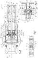
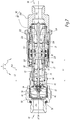
- FIGS. 1 to 8 show a first embodiment of the invention, in which a fluidic male connection element 2 is adapted to be coupled by fitting into a fluidic female connection element 4 to form a connection 6 allowing the circulation of a fluid.
- the connector 6 thus makes it possible to connect in a sealed and reversible manner two systems such as conduits or reservoirs, in order to allow the circulation of a fluid, in particular a pressurized fluid, such as oil.
- the male element 2 comprises a male body 8 including a front part 10, an intermediate part 12 and a rear part 14 nested between them tightly.
- a seal 11 is interposed between parts 10 and 12, while a seal 13 is interposed between parts 12 and 14.
- the male body 8 defines an internal duct 16 which extends between a front orifice 18, or front opening, and a rear orifice 20 or rear opening.
- the front part 10 comprises an outer peripheral locking groove 22 which forms part of a locking device described in more detail in what follows.
- the front 10, intermediate 12 and rear 14 parts are aligned coaxially along a longitudinal axis X2 of the male element 2.
- the male body 8 advantageously has an axial symmetry of revolution about the longitudinal axis X2.
- the male element 2 has an essentially tubular shape extending along the longitudinal axis X2.
- the internal duct 16 has a rear chamber 24 and an intermediate chamber 26.
- the rear chamber 24 extends between the rear port 20 and the intermediate chamber 26.
- the intermediate chamber 26 extends between the rear chamber 24 and the orifice front 18.
- the rear chamber 24 here contains a pressurized fluid.
- element 2 is connected by its rear port 20 to a pipe or to a pressurized fluid reservoir, which is not illustrated.
- the qualifier “front” of a connecting element designates the end of this connecting element which faces towards a complementary connecting element at the start of the coupling of these two connecting elements.
- one part is in "forward abutment” against another part when the part contacts the other part in a direction facing the front of the fitting member.
- the qualifier “rear” designates the end of this connecting element which is opposite to the front.
- one part is “backstop” against another part when the part contacts the other part in a direction toward the rear of the fitting member.
- the pressurized fluid is provided to flow from upstream to downstream from the rear towards the front of element 2. This direction of flow can be reversed according to the application.
- the male element 2 also comprises a front valve 30, a main valve 32 and a safety valve 34, arranged inside the body 8.
- the front valve 30 has the shape of a part of revolution about the longitudinal axis X2.
- the front valve 30 is movable in translation relative to the male body 8 in the intermediate chamber 26 along the longitudinal axis X2 between a position of closure of the front orifice 18 and an open position of the front orifice 18.
- a seal 36 for example in the form of an O-ring, is interposed radially between the front valve 30 and the male body 8 when the front valve 30 is in its closed position, which makes it possible to close the internal duct 16.
- the seal 36 is received in a peripheral groove of the front valve 30.
- the seal 36 is produced here. made of elastomeric material.
- the front face of the front valve 30 and the front face of the male body 8 are aligned with each other when the front valve 30 is in the closed position and the male member 2 is uncoupled.
- the term “radially” is defined with respect to the longitudinal axis X2.
- a so-called radial direction is perpendicular to the axis X2.
- the terms “longitudinal” and “axial” are defined with respect to the longitudinal axis X2.
- a so-called longitudinal or axial direction is parallel to the longitudinal axis X2.
- the main valve 32 is movable in translation relative to the male body 8 in the rear chamber 24 along the axis X2 between a closed position and an open position. In the closed position, the main valve 32 closes the rear chamber 24 on the front by coming into axial abutment against the body 8.
- the main valve 32 here comprises a seal 38, for example in the form of a ring, which is in front abutment against a seat 39 formed by the male body 8 when the main valve 32 is in its closed position.
- a seal 38 for example in the form of a ring, which is in front abutment against a seat 39 formed by the male body 8 when the main valve 32 is in its closed position.
- the seal 38 is here made of an elastomeric material.
- the main valve 32 In the open position, the main valve 32 is in a retracted position from its closed position and a main fluid passage 37 is formed between the seat 39 and the main valve 32, around the main valve 32, for the release. fluid communication between the rear chamber 24 and the intermediate chamber 26.
- the main valve 32 has a central body 40, an intermediate body 42 and a rear body 44 aligned along the axis X2.
- the seal 38 is received in the main body 40.
- the rear body 44 is screwed into the main body 40.
- the intermediate body 42 is screwed in abutment against the rear body 44.
- the main body 40 is drilled right through to form a central passage which, when the main valve 32 is mounted inside the body male 4, extends along the longitudinal axis X2 opening out on the front of the main valve 32 in the intermediate chamber 26 on the one hand, and in a second corresponding central passage of the intermediate body 42 and the rear body 44 on the other hand, this second central passage opening radially into the rear chamber 24 at the level of the rear body 44.
- These various central passages collectively form a secondary passage 46 formed through the main valve 32 between the rear chamber 24 and the chamber intermediate 26.
- the main valve 32 can be in one piece.
- the safety valve 34 is housed inside the main valve 32.
- the safety valve 34 is movable in translation relative to the main valve 32 along the longitudinal axis X2 between a closed position and a position of. 'opening.
- the safety valve 34 closes the secondary passage 46 between the rear chamber 24 and the intermediate chamber 26 by abutting forward against a seat 48 formed by a seal mounted on the intermediate body 42 of the main valve 32.
- the safety valve 34 opens this secondary passage 46.
- the seals 38 and 48 are contact seals, that is to say they come into axial cooperation with the seat 39, the safety valve 34, respectively, when the safety and main valves are in the closed position, in order to limit friction, in opposition to radial cooperation joints such as joint 36.
- the safety valve 34 is housed inside the secondary passage 46 to open or close the secondary passage 46 depending on whether it is in its open or closed position. It is therefore understood that the rear chamber 24 and the intermediate chamber 26 can be placed in fluid communication via the secondary passage 46 even when the main valve 32 is in the closed position.
- the sealing diameter of the safety valve 34 at the seal 48 is less than the sealing diameter of the main valve 32 at the seal 38, in this case more than five times smaller.
- the safety valve 34 is a ball made of metallic material disposed inside the secondary passage 46.
- Element 2 comprises a spring 50 which pushes safety valve 34 back into its closed position abutting against seat 48.
- spring 50 is interposed between the safety valve 34 and the rear body 44 of the main valve 32.
- the spring 50 is a compression coil spring mounted coaxially with the axis X2.
- the rear body 44 of the main valve 32 is here extended by a rear rod 45 extending along the axis X2.
- the rear rod 45 is engaged and guided radially in a rear part 52 housed in the rear chamber 24.
- the rear part 52 is blocked longitudinally in the body 8, that is to say it cannot be locked. move in translation along the X2 axis.
- the rear part 52 is preferably a star, that is to say a rigid mechanical part including arms, here three in number, arranged radially in the shape of a star around a central opening which receives part of the main valve 32, in this case, here, which receives the rear rod 45 throughout the movement of the main valve 32 between its closed position and its open position.
- the rear part 52 forms a rear stop for the main valve 32.
- the main valve 32 in the open position can be driven rearward by the flow of fluid, and the main valve 32 in rear stop against.
- the rear part 52 guarantees a sufficient non-zero fluid passage section around the main valve 32 in the male body 8.
- the position occupied by the main valve 32 in rear abutment against the rear part 52 is represented by the thin line 32 ' on the figure 8 .
- the element 2 also comprises a pusher 54 intended to actuate the safety valve 34.
- the pusher 54 is movable in translation along the axis X2 with respect to the safety valve 34 and with respect to the main valve 32. In addition, in other words, the pusher 54 is not made in one piece with the safety valve 34.
- the pusher 54 is partially accommodated in the main valve 32.
- the pusher 54 extends forward of the main valve 32 being received at least partially in the secondary passage 46 of the main body 40 of the valve. the main valve 32.
- the pusher 54 can move relative to the male body 8 between an advanced position and a retracted position.
- the pusher 54 actuates the safety valve 34, that is to say it opens it, when it is moved to its retracted position.
- the pusher 54 here comprises an elongated body in the form of a rod or of a solid cylinder which extends along the axis X2 and which advantageously has an axial symmetry of revolution about the longitudinal axis X2.
- the external diameter of the pusher 54 is of the order of 3 mm.
- the pusher 54 comprises three axial surfaces, that is to say three surfaces perpendicular to the axis X2, including a rear face 56, a rear shoulder 58 and an intermediate shoulder 60 which are turned towards the rear of the element 2.
- the pusher 54 also has a front face 62.
- Element 2 also includes a washer 64 acting as a support part of the pusher.
- the support piece 64 is received inside the body 4, precisely inside the intermediate chamber 26.
- the support piece 64 can move in translation along the axis X2 to inside the intermediate chamber 26, being guided radially by the internal walls of the front part 10.
- a part that is integral with the pusher or a part mounted on the pusher so that the support part is capable of coming into abutment against the pusher is called a support part of the pusher.
- the support piece 64 preferably comprises a central opening through which the pusher 54 passes.
- the support piece 64 is a star comprising three branches extending radially around the central opening to. the interior of which is received the pusher 54.
- the support part 64 is disposed behind the intermediate shoulder 60 of the pusher 54. It is therefore understood that the support part 64 is not blocked in rearward translation along the pusher 54 between the intermediate shoulder 60 and the main body 40.
- the body 2 also comprises a spring 66 which pushes and maintains the bearing part 64 forward against the intermediate shoulder 60.
- This spring 66 bears rearwardly on the body 4 and bears forward on the part 64.
- the spring 66 pushes the pusher 54 towards its advanced position until it abuts against the main valve 32.
- the spring 66 is a compression coil spring mounted coaxially with the axis X2.
- the axial stop between the pusher 54 and the main valve 32 is provided by one or more thrust balls 70, in this case three balls 70, housed in a peripheral groove 72 of the pusher 54.
- the peripheral groove 72 has a circular shape which extends over the outer periphery of the pusher 54 around the axis X2.
- the balls 70 are integral in translation with the pusher 54.
- Each ball 70 is also engaged with a longitudinal groove 74 carried by the main valve 32, here formed at the level of the surface delimiting the secondary passage 46 in the main body 40.
- the longitudinal grooves 74 extend parallel with the axis X2, are open at the rear and are closed towards the front, that is to say they have a wall or end surface forming a stop preventing the ball 70 to move further forward in the longitudinal groove 74 along the axis X2.
- the stop of pusher 54 against main valve 32 may be formed differently.
- the pusher 54 moves forward and reaches its advanced position, the balls 70 abut against the end surface of the longitudinal grooves 74 and limit the forward movement of the pusher 54 with respect to the male body 8 and with respect to to the main valve 32. In the advanced position, the pusher 54 is therefore in forward abutment against the main valve 32.
- the rear face 56 of the pusher 54 is then at a non-zero distance D2 from the safety valve 34, the safety valve 34 being in its closed position.
- the rear shoulder 58 of the body of the pusher 54 is then located at a non-zero distance D1 from a front face 76 of the intermediate body 42.
- the distance D3 corresponds to the distance between the front face 62 of the pusher 54 and a rear face of the front valve 30 when the pusher 54 is in the advanced position, the front valve 30 and the main valve 32 are closed.
- the distance D3 is not zero.
- the distances D1, D2 and D3 are taken along the longitudinal axis X2.
- a portion of the pusher 54 is disposed with reduced play inside the main body 40 to provide radial guidance of the pusher 54 relative to the main valve 32.
- the length “L1” represents the free length of the pusher 54, measured along the axis X2 from the front face of the main body 40 to the front face 62 of the pusher 54 in the configuration where the safety valve is open.
- the length “L2” represents the distance, measured along the axis X2, between the front face of the main body 40 and a middle plane P64 of the support part 64 in this same configuration.
- the length L2 is equal to half of the length L1, preferably equal to 0.4 to 0.6 times the length L1.
- the support piece 64 is substantially placed in the middle of the free length L1 of the pusher 54 when the safety valve 34 is in the open position. This makes it possible to limit the buckling of the pusher 54 even if the section of the pusher 54 is small.
- the element 2 also comprises a spring 80 which pushes the front valve 30 towards its closed position.
- the spring 80 is interposed between the front valve 30 and the bearing part 64, resting on one face of the bearing part 64 which is oriented opposite the bearing face of the spring 66.
- the spring 80 is here a compression coil spring arranged coaxially with the axis X2.
- the turns of the springs 66 and 80 are aligned along the axis X2, which increases the radial compactness of the male element 2.
- the turns of the springs 66 and 80 are here arranged in an external radial position in the chamber. intermediate 26, which allows their operation to be unimpeded when the fluid circulates around the pusher 54.
- the maximum return force developed by the spring 80 during the movement of the front valve 30 relative to the male body 8 is strictly less than the minimum return force developed by the spring 66 during the movement of the pusher 54 relative to the male body 8.
- the return force developed by the spring 80 is at its maximum in the mated configuration, when the front valve 30 and the main valve 32 are both in the open position. This maximum force is moreover reached as soon as the front valve 30 is in contact with the pusher 54.
- the minimum return force developed by the spring 66 is reached when the pusher is in the advanced position.
- the spring 66 has a stiffness greater than that of the spring 80, so as to be able to exert a return force greater than that of the spring 80.
- connection element 2 is arranged such that, during coupling with a complementary connection element 4 during which the front valve 30 is moved to its open position, the front valve 30 comes into contact with the pusher 54 and moves the pusher 54. The pusher 54 then comes into contact with the safety valve 34 and moves it to the open position of the secondary passage 46 before coming into contact with the main valve 32 and move it to the open position.
- the connection element 2 is arranged such that, upon coupling with a complementary connection element 4, the pusher 54 or the safety valve 34 contacts the main valve 32 to move the main valve 32 from there. its closed position towards its open position.
- the pusher 54 and the main valve 32 are arranged to interact with each other so that the movement of the pusher 54 towards the advanced position causes the main valve 32 to move towards its closed position.
- the assembly formed by the pusher 54 and the main valve 32 is assembled by threading the bearing part 64 from the rear of the pusher 54, then by engaging the main body 40 of the main valve 32 around the pusher 54.
- the balls 70 are then engaged in the peripheral groove 72 then in the longitudinal grooves 74 of the main valve 32.
- the safety valve 34 and the spring 50 acting on this safety valve 34 are then engaged in the rear body 44 .
- the intermediate body 42 is then screwed in abutment on the rear against the rear body 44.
- the sub-assembly formed by the rear body 44 and the intermediate body 42 is then screwed in abutment on the front against the main body 40, with interposition of a seal 82.
- the rear part 52 and the assembly formed by the pusher 54 and the main valve 32 are then placed inside the rear part 14 of the male body 8 then the intermediate part 12 is screwed onto the rear part 14.
- the spring 66 is engaged between the intermediate part 12 and the front support part 64, then the spring 80 is placed around the pusher 54 at the front of the support part 64.
- the front part 10 after having been fitted with the front valve 30, is then screwed into the intermediate part 12.
- the male element 2 is then in its assembled configuration.
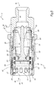
- the figure 5 shows an example of the female connector 4.
- the female element 4 comprises a female body 90 defining an internal duct 92 which extends between a front orifice 94 and a rear orifice 96.
- the reference X4 denotes a longitudinal axis of the female body 90.
- the female body 90 has an essentially tubular shape elongated and centered along the longitudinal axis X4.
- the axis X4 coincides with the axis X2.
- the front orifice 94 is intended to be associated with the front orifice 18 of the element 2 to allow the circulation of the fluid from the element 2 to the element 4.
- the female body 90 here comprises a front part 98 and a rear part 100 which are screwed together in a sealed manner by virtue of a seal 102.
- the element 4 further comprises a slide 104 and a piston 106.
- the slide 104 is movable in translation along the axis X4 relative to the female body 90 between a closed position and an open position of the internal duct 92.
- the piston 106 is for its part fixed relative to the body 90 by being sandwiched between the front part 98 and the rear part 100.
- a spring 105 pushes the spool 104 back to its closed position.
- the spring 105 is a helical compression spring coaxial with the axis X4, interposed between the rear of the spool 104 and a base of the piston 106.
- the drawer 104 cooperates in a sealed manner with the female body 90 by means of a seal 124 housed in an internal peripheral groove 125 of the female body 90 and with the piston 106 by means of a seal 107 housed in an outer peripheral groove of the piston 106.
- the front face 108 of the piston and the front face 110 of the drawer 104 are aligned with one another when the drawer 104 is in the closed position and the female element 4 is uncoupled.
- the female body 90, the front face 108 of the piston 106 and the front face 110 of the slide 104 delimit in uncoupled configuration a reception volume Va of the male element 2 in the female body 90.
- a seal 126 is housed in an internal peripheral groove of the female body 90, in the reception volume Va.
- the female element 4 is also equipped with a locking device 112 intended to lock the element 4 in a configuration coupled with the element 2.
- the locking device 112 is here able to cooperate with the locking groove 22 provided. on the front part 10 of element 2.
- the locking device 112 is a ball locking device.
- the locking device 112 can be made differently. It is therefore understood that, in such a case, the element 2 is adapted accordingly and that the locking groove 22 can be replaced by another device complementary to the locking device 112.
- the locking device 112 comprises locking balls 114, in this case eight, an elongated housing 117 adapted to each receive one of the locking balls 114 in the female body 90, and also comprises a locking ring 118 and an internal ring 120 which cooperates with an internal spring 113 interposed between a stop ring of the female body 90 and the internal ring 120.
- the locking ring 118 is adapted to cover the locking balls 114 with a radial surface internal 119 and keep them in an internal locking position in which they partially protrude into the reception volume Va.
- the inner ring 120 is adapted to axially delimit the longitudinal position of the locking balls 114 in their elongated housing 117.
- the inner ring 120 is movable in translation relative to the female body 90.
- the inner ring 120 and the locking ring 118 are mounted. coaxially around the longitudinal axis X4.
- Reference 122 designates an internal housing of the locking ring 118 behind and recessed from the internal radial surface 119
- reference 116 designates an internal housing of the locking ring 118 in front and recessed of the internal radial surface 119
- the reference 128 designates a stop segment associated with the locking ring 118.
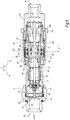
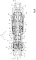
- the figures 6 to 8 show the connector 6 formed by the assembly of the male 2 and female connector elements 4.
- An example of a coupling sequence for coupling the male and female elements 2 and 4 is now described. Items 2 and 4 are shown in the process of coupling on the figures 6 and 7 , while they are coupled on the figure 8 .
- the elements 2 and 4 are aligned so that their respective axes X2 and X4 coincide and their respective front ports 18 and 94 are facing each other. Then elements 2 and 4 are fitted one inside the other. Element 2 is introduced into the reception volume Va.
- the front face of the front valve 30 comes into contact with the front face 108 of the piston 106. Simultaneously, the front face of the front part 10 comes into contact with the front face 110 of the spool 104, since, in the closed position of the valve. drawer, the front face 110 is aligned with the front face 108 of the fixed piston 106.
- the female body 90 at least partially surrounds the male body 8, here at the level of the front part 10 of the male body 8.
- the front face of the male body 8 comes into contact with the locking balls 114 and pushes them towards the front. 'rear in the elongated housing 117, causing the inner ring 120 to move backwards, then radially into the rear inner housing 122.
- the inner ring 120 is pushed back to its retracted position, while the locking ring 118 remains in the forward position , because it is pushed back by a spring 121 mounted under the locking ring 118 until it comes into abutment against the stop segment 124.
- the male body 8 continues its movement until the seal is ensured by the seals 124 and 126 which come into contact and surround the front part 10.
- the drawer 104 is pushed back towards its open position, so that the front faces 108 and 110 are no longer aligned, as illustrated in figure 6 .
- the seal 107 carried by the piston 106 is no longer in contact with the spool 104, so that the internal duct 92 is placed in communication with the intermediate chamber 26.
- the fluid does not leave the chamber. rear chamber 24 since valves 32 and 34 are closed.
- the reference “C1" corresponds to the opening stroke of the male / female communication, that is to say the minimum value of the displacement along the axis X2 of the front valve 30 from its closed position, when 'it is moved as described above at the coupling, to allow the seal 107 of the piston 106 to leave the sealed contact with the male body 8 and to put the intermediate chamber 26 in communication with the internal duct 92.
- the stroke of the forward valve 30 to open the safety valve 34 from the uncoupled configuration is greater than the opening stroke C1 of the male / female communication.
- the front valve 30 is pushed back towards the rear of the male element 2 until it comes into direct contact with the front face 62 of the pusher 54.
- the front valve 30 is pushed back to its open position. by opposing the return force exerted by the spring 80.
- the front valve 30 in abutment on the front face 62 of the pusher 54, causes a retraction of the pusher 54 towards its retracted position. In doing so, the pusher 54 overcomes the return force exerted by the spring 66.
- the spring 80 remains compressed, but is not further compressed during the backward movement of the pusher 54, since the support piece 64 accompanies the movement. retraction of the pusher 54. In fact, the intermediate shoulder 60 presses on the part 64, which drives the support part 64 in translation along the axis X2.
- the pusher 54 has not yet made contact with the safety valve 34, so that the safety valve 34 and the main valve 32 are both in their closed position.
- the fluid contained in the rear chamber 24 cannot, at this stage, enter the intermediate chamber 26.
- the pusher 54 then comes into contact with the safety valve 34. Specifically, the rear face 56 of the pusher 54 rests on the safety valve 34, that is to say here presses on the ball forming the safety valve 34 The safety valve 34 moves back with the pusher 54 under the effect of this support, opposing the return force exerted by the spring 50.
- the safety valve 34 leaves its seat and opens the secondary passage 46, of reduced size, between the intermediate chamber 26 and the rear chamber 24.
- a low flow of fluid can flow from the rear chamber 24 to the intermediate chamber 26 via the secondary passage 46, as illustrated by the arrows F1.
- elements 2 and 4 are still in the process of coupling. Since the fluid communication is open between the internal duct 92 and the chamber 26, this fluid can flow to the internal duct 92, which allows the pressure of the fluid in the rear chamber 24 to be reduced.
- a main fluid passage 37 is formed between the main valve 32 and the male body 8 allowing a flow F2 of fluid, greater than the flow F1, to circulate between the rear chamber 24 and the intermediate chamber 26.
- the fluid circulates towards the internal duct 92 of the female element 4.
- the locking device 112 engages to lock the elements 2 and 4 in the mated state.
- the press-fit movement can no longer be continued.
- elements 2 and 4 cannot be uncoupled from one another without first releasing the locking device 112.
- the fitting movement ends when the locking balls 114 reach opposite the locking groove 22 of the male body 8 and engage therein in the internal locking position.
- the inner ring 120 of the female member 4 is pushed into the advanced position by the spring 113, so that the locking balls 114 are pushed forward in the elongated housing 117 to a position where they are radially covered by the surface.
- the coupling is automatic because only the movement of bringing together the male 8 and female 90 bodies allows the locking device 112 to reach its locked configuration with the locking balls 114 held in engagement in the locking groove 22.
- the main valve 32 is opened and the elements 2, 4 are coupled.
- the sum of the travel stroke of the front valve from its closed position relative to the tappet in the advanced position (distance D3) and the travel of the tappet from its forward position relative to the safety valve ( distance D2) in the closed position is greater than the opening travel C1.
- the front valve 30 here regains radial guidance with the body 8, by cooperating at reduced radial clearance with the inner walls of the internal duct 16, guidance that it had lost after leaving its position. closing, due to a local widening of the internal duct 16 at the front part 10.
- the radial play J1, J1 'between the body 8 and the front valve 30 in its closed position, respectively in its open position is less than the radial clearance J2 between the front valve 30 and the body 8 in the configuration of the figure 7 , in which the front valve 30 is in a longitudinal position intermediate between its closed position and its open position.
- the locking balls 114 are held in the internal locking position by the locking ring 118 and oppose the movement of withdrawal of the male body 8 from the female body 90, therefore the separation of the male 8 and female bodies. 90.
- the pusher 54 In its movement between its advanced position and its retracted position, the pusher 54 is in contact with the front valve 30 only along the longitudinal axis X2.
- the front valve 30 does not have radial contact with the tappet 54. In other words, the front valve 30 does not guide radially and does not radially stress the tappet 54.
- the locking ring 118 is manually retracted rearwardly of the female member 4 to allow the internal housing 116 of the locking ring 118 to be radially opposite the locking balls 114, which allows Locking balls 114 to move apart radially and no longer protrude into the reception volume Va and which allows the female body 90 to be moved away from the male body 8.
- the spool 104 gradually returns to its closed position, under the effect of the spring 105, while the front valve 30 is pushed back to its closed position by the spring 66 .
- the spring 50 pushes the safety valve 34 towards its closed position, which closes the secondary passage 46 and interrupts the circulation of the flow F1 of fluid through the secondary passage 46.
- the spring 66 ensures that the pusher 54 returns. abutting on the front against the main valve 32, which drives the main valve 32 towards its closed position. In other words, the movement of the pusher 54 towards its advanced position drives the main valve 32 in movement towards its closed position. This movement is here provided by a direct action of the pusher 54 on the main valve 32 thanks to the thrust balls 70 and by the spring 66. Once it comes into abutment against the valve 32, the pusher 54 no longer moves relative to the body. 40 of the valve 32, but the assembly formed of the main valve 32 and the pusher 54 continues to move in translation forwards in the internal duct 16 under the action of the spring 66.
- the intermediate chamber 26 is still in communication with the internal duct 92. Indeed, as the restoring force exerted by the spring 80 is weaker than that exerted by the spring 66, the front valve 30 remains in contact with the spring. pusher 54 while the spring 66 pushes the bearing part 64 forward.
- the pusher 54 can no longer move further forward, since it is already in front stop on the main valve 32.
- the spring 66 does not can no longer continue to relax, since the intermediate shoulder 60 prevents the support piece 64 from going further.
- the spring 80 in turn relaxes and pushes the front valve 30 towards its closed position, since it is not strong enough with respect to the spring 66 to push the support piece 64 back.
- the front valve 30 leaves the front face 62 of the pusher 54.
- the front valve 30 remains in contact with the front face of the piston 106 and, as the female element 4 is withdrawn from the male element 2, the drawer 104 returns to its closed position.
- the front valve 30 finally resumes sealing with the male body 8 and the spool 104 resumes sealing with the female body 90 and with the piston 106.
- the intermediate chamber 26 is closed, as is the internal duct 92.
- the connector elements 2 and 4 can be completely separated and are ready for another connection.
- the main valve 32 is floating, that is to say it is not subjected to any elastic force with respect to the male body 8. This ensures, during uncoupling, that the safety valve 34 will be closed before the main valve 32 closes.
- the behavior of the safety valve 34 and of the main valve 32 follows a predefined sequence during coupling and during uncoupling.
- the main valve 32 only opens after the safety valve 34 which itself opens only after the elements 2 and 4 have been fitted and the communication of fluid between elements 2 and 4 is ensured.
- this makes it possible to lower the pressure in the rear chamber 24 before the opening of the main valve 32.
- the safety valve 34 and the main valve 32 are closed before closing the fluid communication between the connectors 2 and 4.
- the springs 66 and 80 are supported on the same part 64, it is not necessary to further compress the spring 80 to open the safety valve 34 and the main valve 32.
- the return force of the spring 80 weaker than the return force of the spring 66 guarantees the reverse uncoupling sequence to the coupling sequence, i.e. the closing of the main valve 32 and the safety valve 34 before the closing of the fluid communication between intermediate chamber 26 and internal duct 92 and the closing of the front valve 30. This prevents leakage of pressurized fluid into the intermediate chamber 26 at the time of uncoupling, which makes it possible to keep an intermediate chamber 26 having a lower pressure so that it can easily be pushed back. the front valve 30 on subsequent connection.
- the front valve 30 is no longer guided radially by the male body 8 in an intermediate position, in particular when the front valve 30 comes into contact with the tappet 54 and as long as the main valve 32 is not not moved to its open position, and as the front valve 30 does not radially guide the pusher 54, the risks of jamming between the moving parts are avoided.
- components described with reference to the male connector member may alternatively be mounted on a female connector member and vice versa.
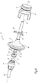
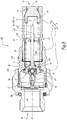
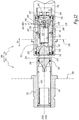
- FIGS 9 to 11 show a second embodiment of the invention in which a male connector element 202 is adapted to be coupled by fitting into a female connector element 204 to form a connector 206 allowing the circulation of a fluid.
- the connecting elements 202 and 204 are here intended to play a role similar to that of the connecting elements 2 and 4.
- the constituents of these connecting elements 202 and 204 which are similar to those of the connecting elements according to the first embodiment previously described bear the same references and are not described in more detail, insofar as the above description can be transposed to them. Only the constituents showing notable differences are described in the following.
- the connecting element 202 differs in particular from the connecting element 2, in that the stop of the pusher 254 on the main valve 232 is provided by a flange 210 of the pusher 254 resting on the flat bottom of a recess 212 formed. in the valve main 232.
- the thrust balls 70 are omitted, as are the peripheral groove 72 and the longitudinal grooves 74.
- the main valve 232 here has the same function as the main valve 32, but has a different shape.
- the safety valve 34 is pushed back by a spring 250 similar to the spring 50 but which is here interposed between the safety valve 34 and the rear part 52 integral with the male body 8.
- the spring 250 is not in press on the main valve 232.
- the rear part 52 cooperates radially with the main valve 232 for its guidance by being engaged in the main valve 232 throughout the movement of the main valve 232 between its closed position and its open position.
- the support part 64 is held integral in translation with the pusher 254 by being placed between a stop segment 214 and a shoulder surface 216 integral with the pusher 254.
- the stop segment 214 is placed at the end. 'front of the backing piece 64 while the shoulder surface 216 is placed behind the backing piece 64 and faces towards the front hole 18.
- the backing piece support 64 is mounted from the front of the pusher 254.
- the spring 80 is here in abutment between the support part 64 and the front valve 30.
- the spring 66 which rests between the support part 64 and the body 8 According to a variant that is not illustrated, the support piece 64 can be integral with the pusher 54.
- the connecting element 204 is in turn similar to the connecting element 4.
- the coupling sequence of the elements 202 and 204 is similar to that previously described for elements 2 and 4, except that the pusher 254 here indirectly actuates the main valve 232 on opening through the valve. 34.
- the front valve 30 pushes back the pusher 254, the rear face 56 of which pushes the safety valve 34 and opens the secondary passage 46 between the rear chamber 24 and the intermediate chamber 26. This causes the fluid pressure in chamber 24 to drop.
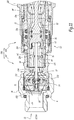
- the figures 12 to 14 show a third embodiment of the invention, in which a male connector element 302 is adapted to be coupled by fitting into a female connector element 304 to form a connector 306 allowing the circulation of a fluid.
- the connection elements 302 and 304 according to this third embodiment are intended to play the same role as the connection elements described above.
- the connecting elements 302 and 304 are mounted on plates 308 intended to be brought together to facilitate the fitting of the elements 302 and 304 and then to be kept close together. the other when the elements 302 and 304 are coupled.
- the plates 308 extend perpendicularly to the respective longitudinal axes X302 and X304 of the elements 302 and 304.
- a notable difference from the first and second embodiments is that the front, safety and main valves previously described here belong to the female member 304.
- the male element 302 comprises a male body 310 which defines an internal duct 312 and a male valve 314 movable in translation in the internal duct 312, along the longitudinal axis X302, between a closed position and an open position of a front orifice of the element 302.
- a spring 316 pushes the male valve 314 towards its closed position.
- the plate 308 of the element 302 is integral with the male body 310.
- the male valve 314 here comprises a seal 318 similar to the seal 36.
- the female element 304 includes a female body 320 which delimits an internal duct 321 similar to the internal duct 16 and which comprises a front orifice 323, an intermediate chamber 322 and a rear chamber 324 which play the same role as the chambers 26 and 24, respectively.
- the rear chamber 324 is able to contain a pressurized fluid and opens onto a rear orifice of the element 304 which is extended by a duct 326 for example connected to a pipe or to a pressurized fluid reservoir, not shown.
- pressurized fluid is provided to flow from element 304 to element 302.
- the female body 320 comprises a piston 328 radially and longitudinally integral with the female body.
- the piston 328 has the shape of a part of revolution about the longitudinal axis X304 in which passages are formed for the fluid.
- the female element 304 comprises a slide 330 movable in translation along the longitudinal axis X304, which acts as a front valve similar to the front valve 30.
- the front valve 330 is interposed radially between the piston 328 and the female body 320 and movable between a closed position in which the front valve 330 cooperates in a sealed manner with the female body 320 and the piston 328 and in which the front valve 330 is guided radially by the female body 320, and a retracted open position of the duct internal 321 at the front port 323.
- Element 304 also includes a main valve 332, a safety valve 334 and a tappet 336, which have a role analogous to valves 32 and 34 and tappet 54, respectively.
- the pusher 336 has a bell shape and is mounted partly around the piston 328 and partly inside the piston 328.
- the main valve 332 in the closed position abuts forward against the piston 328 when the connector member 304 is uncoupled.
- the seal between the main valve 332 and the piston 328 is achieved by a radial seal 340 disposed between the main valve 332 and the piston 328.
- the safety valve 334 has the shape of a part of revolution and cooperates in the closed position with a seat 342 of the main valve and closes a secondary passage 344 between the rear chamber 324 and the intermediate chamber 322 to through the main valve 332.
- a forward stem 348 of the safety valve 334 projecting forward of the seat 342 and forward of the main valve 332, is engaged with reduced radial play in the tappet 336.
- the pusher 336 is not engaged in the main valve 332.
- a stop segment 350 integral with the front rod 348 limits the movement of the pusher 336 forward with respect to the safety valve 334.
- a shoulder 349 facing towards the front is provided on the front rod 348.
- a support piece 352 playing the same role as the support piece 64, is disposed in the chamber 322 while being mounted coaxially around the piston 328 and the pusher 336.
- the support piece 352 is held together longitudinally of the pusher. 336 between a stop ring and a shoulder of the pusher 336.
- the springs 80 and 66 are disposed radially outside the piston 328.
- the spring 80 is interposed between the support part 352 and the piston 328.
- the spring 66 is interposed between part 352 and a base of the front valve 330.
- the turns of the springs 80 and 66 are aligned along the axis X304. When the connection element 304 is in the uncoupled configuration, the spring 66 returns the pusher 336 forward, via the support piece 352.
- the support piece 352 does not provide here no radial guidance of the pusher 336. This guidance is provided by the outer surface of the piston 328. In its advanced position, the pusher 336 abuts forward against the safety valve 334, the safety valve being in abutment before against its seat 342 on the main valve 332 and the main valve 332 being in forward abutment against the piston 328.
- the distance D2 is defined between a rear face of the pusher 336 and the shoulder 349 intended to come into contact with one another. for moving the safety valve 334 to its open position.
- the male valve 314 Upon mating, the male valve 314 contacts the head of the piston 328 and recedes relative to the male body 310. Simultaneously, the male body 310 pushes the front valve 330 back to its open position against the valve. spring 80, the spring 66 developing a return force much greater than the return force of the spring 80.
- the front valve 330 moving backwards, bears on the front face of the pusher 336, after a stroke of the value of the distance D3 defined as before, and pushes it back.
- the pusher 336 moves back until it rests on the shoulder 349 of the rod 348 to push the safety valve 334 and thus open the secondary passage 344 between the rear chamber 324 and the intermediate chamber 322.
- the opening of the secondary passage 344 is carried out after the fluid communication between the internal duct 312 and the intermediate chamber 322 is effective because the stroke C1 defined as above is less than the sum of the distance D2 and the distance D3.
- the fluid flow F1 then flows towards the intermediate chamber 322 then towards the internal duct 312, which lowers the pressure in the rear chamber 324.
- the front valve 330 is no longer guided radially by the female body. 320.
- the fitting movement of the elements 302 and 304 continues, so that the pusher 336 continues to move back until the rear face 337 of the pusher 336 comes into contact with a front face 339 of the main valve 332. it pushes back into its open position.
- the flow F2 of fluid greater than the flow F1 then flows at the level of the main passage 37 around the main valve 332, between the female body 320 and the main valve 332, from the rear chamber 324 to the intermediate chamber 322.
- the front valve 330 is guided radially by the outer radial surface of the piston 328.
- the front valve 330 is here guided radially by an element integral with the body 320.
- the radial play J1, J1 'between the piston 328, integral with the body 320, and the front valve 330 in its closed position, respectively in its open position, is less than the radial clearance J2 between the piston 328 and the front valve 330 in the configuration of the figure 13 , in which the front valve 330 is in an intermediate longitudinal position between its closed position and its open position, due to a local narrowing of the outside diameter of the piston 328.
- pusher 336 follows the retracting motion of forward valve 330, maintaining contact between pusher 336 and forward valve 330 , since the return force of the spring 66 is greater than the return force of the spring 80.
- the pusher 336 abuts against the stop segment 350 and drives the safety valve 334 towards its closed position in abutment against its seat 342.
- the secondary passage 344 is thus closed and the flow F1 is interrupted.
- the spring 66 then exerts its return force also on the main valve 332 which in turn closes.
- the intermediate chamber 322 is isolated from the rear chamber 324 and the flow F2 is in turn interrupted. At this stage, the fluid communication between the internal duct 312 and the intermediate chamber 322 is still effective.
- the spring 80 pushes the front valve 330 back to its closed position.
- an additional spring may be provided which bears on the safety valve 334 and on the main valve 332 or the female body 320 and which pushes the safety valve 334 into the closed position.
- a safety valve and a tappet can be provided both in the male element and in the female element intended to be coupled to form the fitting, when one or the other of the internal ducts can be subjected. at high fluid pressure.
- the ball forming the safety valve 34 may be replaced in the first and second embodiments by a cylindrical shaped safety valve.
Landscapes
- Engineering & Computer Science (AREA)
- General Engineering & Computer Science (AREA)
- Mechanical Engineering (AREA)
- Quick-Acting Or Multi-Walled Pipe Joints (AREA)
- Safety Valves (AREA)
Claims (15)
- Fluidisches Kupplungselement (2; 202; 304), aufweisend:- einen Körper (8; 320), der einen Innenkanal (16; 321) begrenzt, der sich entlang einer Längsachse (X2; X304) erstreckt, wobei der Innenkanal eine hintere Kammer (24; 324) und eine Zwischenkammer (26; 326), die an einer vorderen Öffnung (18; 323) des Innenkanals mündet, umfasst;- ein Hauptventil (32; 232; 332), das translatorisch in der hinteren Kammer (24; 324) zwischen einer Verschlussstellung, in der das Hauptventil (32; 232; 332) im Anschlag gegen den Körper (8; 320) ist, und einer Offenstellung, in der ein Hauptdurchgang (37) zwischen dem Hauptventil (32; 232; 332) und dem Körper (8; 320) für die Fluidverbindung zwischen der hinteren Kammer und der Zwischenkammer eingearbeitet ist, beweglich ist;- ein vorderes Ventil (30; 330), das translatorisch in der Zwischenkammer (26; 326) zwischen einer Verschlussstellung und einer Offenstellung der vorderen Öffnung (18; 323) beweglich ist, wobei das vordere Ventil in die Verschlussstellung durch eine erste Feder (80) gedrückt wird;- ein Sicherheitsventil (34; 334), das translatorisch zwischen einer Offenstellung eines Nebendurchgangs (46; 344), der durch das Hauptventil (32; 232; 332) zwischen der hinteren Kammer (24; 324) und der Zwischenkammer (26; 326) eingearbeitet ist, und einer Verschlussstellung des Nebendurchgangs beweglich ist, in der das Sicherheitsventil (34; 334) im vorderen Anschlag gegen das Hauptventil (32; 232; 332) ist;- ein Stößel (54; 254; 336), der in dem Körper (8; 23) zwischen einer vorgerückten Position und einer zurückgezogenen Position beweglich ist, wobei der Stößel in Bezug auf das Sicherheitsventil (32; 232; 332) entlang der Längsachse (X2; X304) beweglich ist;wobei das Kupplungselement (2; 202; 304) dadurch gekennzeichnet ist, dass:
wobei das Kupplungselement (2; 202; 304) derart ausgebildet ist, dass bei einem Kuppeln mit einem komplementären Kupplungselement (4; 204; 302), während dem das vordere Ventil (30; 330) in seine Offenstellung der vorderen Öffnung verschoben wird, das vordere Ventil in Kontakt mit dem Stößel (54; 254; 336) kommt und den Stößel in die zurückgezogenen Stellung verschiebt, wobei der Stößel in Kontakt mit dem Sicherheitsventil (34; 334) kommt und es in die Offenstellung des Nebendurchganges (46; 344) verschiebt, bevor das Hauptventil (32; 232; 332) in seine Offenstellung verschoben wird;- es eine zweite Feder (66) aufweist, die in der Zwischenkammer (26; 326) in Anlage an dem Körper und an ein Anlageteil (64; 352) des Stößels (54; 254; 336) angeordnet ist und den Stößel (54; 254; 336) in seine vorgerückte Position drückt,- in der vorgerückten Position des Stößels das Hauptventil (32; 232; 332) und das Sicherheitsventil (34; 334) in der Verschlussstellung sind und der Stößel (54; 254; 336) im vorderen Anschlag gegen das Hauptventil (32; 232; 332) oder gegen das Sicherheitsventil (34; 334) ist. - Kupplungselement (2; 202) nach Anspruch 1, dadurch gekennzeichnet, dass in der vorgerückten Position der Stößel (54; 254) im vorderen Anschlag gegen das Hauptventil (32; 232; 332) ist und dass das Kupplungselement eine dritte Feder (50; 250) aufweist, die das Sicherheitsventil (34; 334) in seine Verschlussstellung des Nebendurchgangs (46; 344) zurückbringt.
- Kupplungselement (2) nach Anspruch 2, dadurch gekennzeichnet, dass die dritte Feder (50) zwischen dem Sicherheitsventil (34) und dem Hauptventil (32) liegt.
- Kupplungselement (2) nach Anspruch 2 oder Anspruch 3, dadurch gekennzeichnet, dass der Stößel (54) im vorderen Anschlag gegen das Hauptventil (32) mithilfe mindestens einer Kugel (70) ist, die in einer Längsnut (74) des Hauptventils (32) und einer Umfangskehle (72) des Stößels (54) lagert.
- Kupplungselement (2) nach Anspruch 1, dadurch gekennzeichnet, dass in der vorgerückten Position der Stößel (336) im vorderen Anschlag gegen das Sicherheitsventil (334) ist und dass ein vorderer Stab (348) des Sicherheitsventils (334), der zu dem Hauptventil (332) nach vorn übersteht, in den Stößel (336) eingreift.
- Kupplungselement (2; 202; 302) nach einem der vorhergehenden Ansprüche, dadurch gekennzeichnet, dass das Kupplungselement (2; 202; 304) derart ausgebildet ist, dass bei einem Kuppeln mit einem komplementären Kupplungselement (4; 204; 302) der Stößel (54; 254; 336) oder das Sicherheitsventil (34; 334) in Kontakt mit dem Hauptventil (32; 232; 332) zum Verschieben des Hauptventils von seiner Verschlussstellung in seine Offenstellung kommt.
- Kupplungselement nach einem der vorhergehenden Ansprüche, dadurch gekennzeichnet, dass die erste Feder (80) in Anlage an dem vorderen Ventil (30; 330) und an dem Anlageteil (64, 352) des Stößels (54; 254; 336) angeordnet ist.
- Kupplungselement (2; 202; 302) nach Anspruch 7, dadurch gekennzeichnet, dass die erste Feder (80) und die zweite Feder (66) Spiraldruckfedern sind, deren Windungen entlang der Längsachse (X2; X304) ausgerichtet sind und in einer radialen äußeren Position in dem Innenkanal (16; 321) angeordnet sind.
- Kupplungselement (2; 202; 302) einem der vorhergehenden Ansprüche, dadurch gekennzeichnet, dass die von der zweiten Feder (66) ausgeübte Rückstellkraft, wenn der Stößel (54; 254; 336) in seiner vorgerückten Position ist, größer als die von der ersten Feder (80) ausgeübte Rückstellkraft ist, wenn das vordere Ventil (30; 330) und das Hauptventil (32; 232; 332) in der Offenstellung sind.
- Kupplungselement (2; 202) nach einem der vorhergehenden Ansprüche, dadurch gekennzeichnet, dass das Anlageteil (64) des Stößels (54; 254) angepasst ist, radial den Stößel im Inneren des Körpers (8) in seiner Bewegung zwischen der vorgerückten Position und der zurückgezogenen Position zu führen, wobei das Anlageteil (64) des Stößels im Wesentlichen in der Mitte der freien Länge (L1) des Stößels (54; 254) liegt, wenn das Sicherheitsventil (34) in der Offenstellung ist.
- Kupplungselement (2; 202; 302) nach einem der vorhergehenden Ansprüche, dadurch gekennzeichnet, dass in der Offenstellung und in der Schließstellung der vorderen Öffnung (18; 323) das vordere Ventil (30; 330) mit dem Körper (8) oder mit einem mit dem Körper (320) verbundenen Element (328) mit einem radialen Spiel (J1, J1') zusammenarbeitet, das geringer ist als ein radiales Spiel (J2) zwischen dem Körper (8) bzw. dem mit dem Körper (320) verbundenen Element (328) und dem vorderen Ventil (30; 330) in einer Zwischenstellung des vorderen Ventils (30; 330) zwischen der Verschlussstellung und der Offenstellung der vorderen Öffnung (18; 323).
- Kupplungselement (2; 202) nach einem der vorhergehenden Ansprüche, dadurch gekennzeichnet, dass es ein hinteres Teil (52) aufweist, das in der hinteren Kammer (24) angeordnet ist und radial das Hauptventil (32; 232) führt, wobei das hintere Teil (52) einen hinteren Anschlag für die Bewegung des Hauptventils in dem Körper (8) bildet.
- Kupplungselement (2; 202; 302) nach einem der vorhergehenden Ansprüche, dadurch gekennzeichnet, dass das vordere Ventil (30; 330) geeignet ist, in Kontakt mit dem Stößel (54; 254; 336) nur in einer Richtung parallel zu Längsachse (X2; X304) zu kommen.
- Kupplungselement (2; 202; 302) nach einem der vorhergehenden Ansprüche, dadurch gekennzeichnet, dass das Anlageteil (64; 352) ein zum Stößel (54; 254; 336) getrenntes Teil ist, das im vorderen Anschlag gegen den Stößels durch eine zweite Feder (66) gehalten wird.
- Kupplung (6; 206; 306), die ein Kupplungseinsteckelement (2; 202; 302) und ein Kupplungsaufnahmeelement (4; 204; 304) in komplementären Formen aufweist, die geeignet sind, ineinander gesteckt zu werden, um eine Fluidverbindung eines Innenkanals (16; 312) des Einsteckelementes mit einem Innenkanal (92; 321) des Aufnahmeelementes sicherzustellen, wobei mindestens eines des Kupplungseinsteckelementes und Kupplungsaufnahmeelementes nach einem beliebigen der vorhergehenden Ansprüche ausgebildet ist, dadurch gekennzeichnet, dass die Summe:- des Abstandes (D3) entlang der Längsachse (X2; X304) zwischen dem vorderen Ventil (30; 330) in der Verschlussstellung der vorderen Öffnung (18; 323) und dem Stößel (54; 254; 336) in der vorgerückten Position,- und des Abstandes (D2) entlang der Längsachse (X2) zwischen dem Stößel (54; 254; 336) in der vorgerückten Position und dem Sicherheitsventil (34; 334) in der Verschlussstellung größer ist als der Öffnungsweg (C1) des vorderen Ventils (30; 330) für die Fluidverbindung zwischen dem Innenkanal des Einsteckelementes und dem Innenkanal des Aufnahmeelementes.
Applications Claiming Priority (1)
| Application Number | Priority Date | Filing Date | Title |
|---|---|---|---|
| FR1853212A FR3080165B1 (fr) | 2018-04-12 | 2018-04-12 | Element de raccord et raccord comprenant un tel element de raccord |
Publications (2)
| Publication Number | Publication Date |
|---|---|
| EP3553363A1 EP3553363A1 (de) | 2019-10-16 |
| EP3553363B1 true EP3553363B1 (de) | 2020-09-09 |
Family
ID=62597731
Family Applications (1)
| Application Number | Title | Priority Date | Filing Date |
|---|---|---|---|
| EP19168583.3A Active EP3553363B1 (de) | 2018-04-12 | 2019-04-11 | Kupplungselement und kupplungsvorrichtung mit solchem kupplungselement |
Country Status (5)
| Country | Link |
|---|---|
| US (1) | US11009165B2 (de) |
| EP (1) | EP3553363B1 (de) |
| CN (1) | CN110375137B (de) |
| ES (1) | ES2824824T3 (de) |
| FR (1) | FR3080165B1 (de) |
Families Citing this family (4)
| Publication number | Priority date | Publication date | Assignee | Title |
|---|---|---|---|---|
| DE102020205694A1 (de) * | 2020-05-06 | 2021-11-11 | Robert Bosch Gesellschaft mit beschränkter Haftung | Schnellkuppler mit seitlichen Betätigungshebeln |
| US11780275B2 (en) | 2020-09-02 | 2023-10-10 | Deere & Company | Valve fitting for a tire assembly of a working vehicle equipped with a central tire inflation system (CTIS) |
| IT202000025828A1 (it) * | 2020-10-30 | 2022-04-30 | Faster Srl | Multiconnessione a piastra per il collegamento automatico di linee idrauliche |
| CN115628338A (zh) * | 2022-10-28 | 2023-01-20 | 中航光电科技股份有限公司 | 具有缓压插合功能的液压连接器 |
Family Cites Families (43)
| Publication number | Priority date | Publication date | Assignee | Title |
|---|---|---|---|---|
| US3646964A (en) * | 1967-02-28 | 1972-03-07 | Parker Hannifin Corp | Coupling device for permitting coupling under trapped pressure |
| US3680591A (en) * | 1970-05-07 | 1972-08-01 | Dempco | Unique hydraulic coupler |
| EP0034312B1 (de) * | 1980-02-14 | 1985-01-16 | Aeroquip GmbH | Auch unter Druck kuppelbare Schnellverschlusskupplung |
| US4373551A (en) * | 1981-01-12 | 1983-02-15 | Deere & Company | Dripless coupler |
| US4540021A (en) * | 1984-03-21 | 1985-09-10 | Aeroquip Corporation | Balanced valve coupling |
| SE468403B (sv) * | 1990-01-17 | 1993-01-11 | Dart Engineering Ag | Anordning vid kopplingsdel som innefattar tryckreduceringsorgan |
| US5383492A (en) * | 1993-08-25 | 1995-01-24 | Dormont Manufacturing Co. | Gas connector assembly |
| IT1270182B (it) * | 1994-06-08 | 1997-04-29 | Stucchi Srl | Raccordo ad innesto rapido per tubazioni,dotato di una valvola di sicurezza |
| AU4854596A (en) * | 1995-01-06 | 1996-07-24 | Colder Products Company | Low spill high flow quick coupling valve assembly |
| IT1286038B1 (it) * | 1996-10-25 | 1998-07-07 | Stucchi Srl | Raccordo a innesto rapido per tubazioni con valvola di sicurezza e valvola di scarico di pressione |
| JP4245202B2 (ja) * | 1998-01-09 | 2009-03-25 | イハラサイエンス株式会社 | バルブを有するカプラー |
| US6056010A (en) * | 1998-07-23 | 2000-05-02 | Aeroquip Corporation | Anti-check low spill fluid coupling |
| US6095190A (en) * | 1998-11-17 | 2000-08-01 | Snap-Tite Technologies, Inc. | Coupling with female half having internal pressure relief |
| JP2002005377A (ja) * | 2000-06-20 | 2002-01-09 | Nifco Inc | 電子機器の冷却媒体用チューブのコネクター |
| DE10217922B4 (de) * | 2002-04-22 | 2011-02-24 | TEMA Ingenjörsfirman AB | Schnellkupplung |
| JP3878903B2 (ja) * | 2002-10-25 | 2007-02-07 | 日東工器株式会社 | 管継手 |
| US20050103387A1 (en) * | 2003-11-14 | 2005-05-19 | Voege James A. | Quick connect apparatus |
| DE102004055001A1 (de) * | 2004-11-15 | 2006-05-18 | Tema Marketing Ag | Schnellkupplung |
| US7568502B2 (en) * | 2005-06-01 | 2009-08-04 | Parker-Hannifin Corporation | Coupling for a hydraulic or pneumatic assembly |
| KR100961431B1 (ko) * | 2008-02-25 | 2010-06-09 | 볼보 컨스트럭션 이키프먼트 홀딩 스웨덴 에이비 | 압력제어밸브 |
| CN201420920Y (zh) * | 2009-05-25 | 2010-03-10 | 熊贺永 | 防泄漏内泄压快速连接头 |
| FR2950950B1 (fr) * | 2009-10-01 | 2012-12-07 | Staubli Sa Ets | Element femelle de raccord rapide et raccord rapide incorporant un tel element |
| EP2407701B1 (de) * | 2010-07-16 | 2012-10-31 | Faster S.p.A. | Kompakter Kartuschenanschluss |
| US20130112286A1 (en) * | 2011-04-29 | 2013-05-09 | Fern Kirouac | Quick-connect coupling |
| CN102392619B (zh) * | 2011-07-21 | 2014-09-17 | 北京华油油气技术开发有限公司 | 一种油管携带可回收井下安全阀 |
| JP5561492B2 (ja) * | 2011-11-04 | 2014-07-30 | Smc株式会社 | チェック弁 |
| US8960726B2 (en) * | 2011-11-23 | 2015-02-24 | Parker-Hannifin Corporation | Coupling lock mechanism |
| AU2012101611A4 (en) * | 2012-10-31 | 2012-12-13 | Hoover Manufacturing Company Limited | Quick Connector and Sprayer |
| BR102013016280A2 (pt) * | 2013-06-25 | 2015-08-18 | Dynamics Do Brasil Metalurgia Ltda | Aperfeiçoamento em engate hidráulico para acoplamento rápido |
| EP3045590A4 (de) * | 2013-09-13 | 2017-05-10 | Volvo Construction Equipment AB | Schwimmerventil für baumaschine |
| ITMI20131865A1 (it) * | 2013-11-11 | 2015-05-12 | Stucchi Spa | Innesto per la trasmissione di fluidi con camma scarica pressione. |
| ITMI20131864A1 (it) * | 2013-11-11 | 2015-05-12 | Stucchi Spa | Innesto per la trasmissione di fluidi con guarnizione radiale. |
| ITMI20131866A1 (it) * | 2013-11-11 | 2015-05-12 | Stucchi Spa | Innesto a faccia piana per trasmissione fluidi con guarnizione frontale anulare. |
| CH708930A1 (de) * | 2013-12-06 | 2015-06-15 | Liebherr Machines Bulle Sa | Druckbegrenzungsventil. |
| DE102014010570B4 (de) * | 2014-07-16 | 2023-10-12 | U.M. Gewerbeimmobilien Gmbh & Co. Kg | Kupplungsteil für eine Kupplung für Druckmittelleitungen |
| US9726311B2 (en) * | 2014-10-15 | 2017-08-08 | Faster S.P.A. | Multi-coupling device with pressure relief circuit |
| FR3029263B1 (fr) * | 2014-12-01 | 2017-01-27 | Staubli Sa Ets | Raccord fluidique coaxial |
| US10156310B2 (en) * | 2015-11-18 | 2018-12-18 | Parker-Hannifin Corporation | Non-spill connect under pressure coupler |
| CN108779896B (zh) * | 2015-12-03 | 2021-04-27 | 工程控制国际有限责任公司 | 低排放喷嘴和接收器 |
| FR3046211B1 (fr) * | 2015-12-23 | 2018-02-16 | Staubli Sa Ets | Element male ou femelle de raccord rapide et raccord rapide comprenant un tel element |
| FR3046209B1 (fr) * | 2015-12-23 | 2018-02-16 | Staubli Faverges | Element femelle de raccord rapide et raccord rapide comprenant un tel element femelle |
| EP3244114B1 (de) * | 2016-05-09 | 2019-01-30 | Faster S.p.A. | Integrierte flachabdichtende kartusche |
| FR3082588B1 (fr) * | 2018-06-15 | 2020-09-11 | Staubli Sa Ets | Raccord fluidique |
-
2018
- 2018-04-12 FR FR1853212A patent/FR3080165B1/fr not_active Expired - Fee Related
-
2019
- 2019-03-29 US US16/369,213 patent/US11009165B2/en active Active
- 2019-04-11 CN CN201910290445.0A patent/CN110375137B/zh active Active
- 2019-04-11 EP EP19168583.3A patent/EP3553363B1/de active Active
- 2019-04-11 ES ES19168583T patent/ES2824824T3/es active Active
Also Published As
| Publication number | Publication date |
|---|---|
| US20190316718A1 (en) | 2019-10-17 |
| CN110375137A (zh) | 2019-10-25 |
| ES2824824T3 (es) | 2021-05-13 |
| FR3080165B1 (fr) | 2020-05-01 |
| EP3553363A1 (de) | 2019-10-16 |
| CN110375137B (zh) | 2022-09-30 |
| FR3080165A1 (fr) | 2019-10-18 |
| US11009165B2 (en) | 2021-05-18 |
Similar Documents
| Publication | Publication Date | Title |
|---|---|---|
| EP3553363B1 (de) | Kupplungselement und kupplungsvorrichtung mit solchem kupplungselement | |
| EP3227595B1 (de) | Koaxialfluidverbinder | |
| EP1916464B1 (de) | Verbindungssteckerelement und Verbindungsstück, das ein solches Element umfasst | |
| EP3184871B1 (de) | Steckanschlusselement oder buchse eines schnellanschlusses, und ein solches element umfassender schnellanschluss | |
| EP2669560B1 (de) | Vorrichtung zur Entlastung und zum Ablassen, Anschlusstrichter und Anschluss, der eine solche Vorrichtung umfasst | |
| EP3581836B1 (de) | Flüssigkeitskupplung | |
| FR2919040A1 (fr) | Coupleur a billes perfectionne | |
| EP3670992B1 (de) | Anschlussbuchse und fluidanschluss, der ein steckanschlusselement sowie diese anschlussbuchse umfasst | |
| EP3599408B1 (de) | Schnellkupplung für die lösbare verbindung von zwei rohren, durch die eine flüssigkeit unter druck fliesst | |
| EP0890054A1 (de) | Abgedichtete schnell-kupplung | |
| FR2693250A1 (fr) | Raccord de liaison pour conduites hydrauliques. | |
| EP0877891B1 (de) | Abgedichtete schnell-kupplung | |
| EP3926225A1 (de) | Verbindungsvorrichtung und verbindungsgruppe | |
| EP3306167B1 (de) | Schnellverbinder | |
| EP4306837A1 (de) | Anschlusselement für eine fluidverbindung an ein endgerät | |
| EP3411616B1 (de) | Verbindungsvorrichtung und verfahren | |
| EP2587109B1 (de) | Anschlussvorrichtung | |
| EP1427621B1 (de) | Hauptbremszylinder mit verkürztem ventil-todweg | |
| EP1963729B1 (de) | Steife kopplungsvorrichtung für leitungen mit unter druck stehenden flüssigkeiten | |
| EP3798490B1 (de) | Fluidanschlusselement | |
| WO1997011302A1 (fr) | Raccord rapide pour conduites de fluide sous pression | |
| EP0778190A1 (de) | Verfahren zur Zusammenstellung einer Betätigungszylindervorrichtung einer hydraulischen Kupplung eines Kraftfahrzeuges | |
| EP4682418A1 (de) | Schutzschalter und druckflüssigkeitshandhabungsanlage mit einem solchen schutzschalter | |
| EP4685379A1 (de) | Fluidverbindungselement und -anordnung | |
| BE572848A (de) |
Legal Events
| Date | Code | Title | Description |
|---|---|---|---|
| PUAI | Public reference made under article 153(3) epc to a published international application that has entered the european phase |
Free format text: ORIGINAL CODE: 0009012 |
|
| STAA | Information on the status of an ep patent application or granted ep patent |
Free format text: STATUS: THE APPLICATION HAS BEEN PUBLISHED |
|
| AK | Designated contracting states |
Kind code of ref document: A1 Designated state(s): AL AT BE BG CH CY CZ DE DK EE ES FI FR GB GR HR HU IE IS IT LI LT LU LV MC MK MT NL NO PL PT RO RS SE SI SK SM TR |
|
| AX | Request for extension of the european patent |
Extension state: BA ME |
|
| STAA | Information on the status of an ep patent application or granted ep patent |
Free format text: STATUS: REQUEST FOR EXAMINATION WAS MADE |
|
| GRAP | Despatch of communication of intention to grant a patent |
Free format text: ORIGINAL CODE: EPIDOSNIGR1 |
|
| STAA | Information on the status of an ep patent application or granted ep patent |
Free format text: STATUS: GRANT OF PATENT IS INTENDED |
|
| 17P | Request for examination filed |
Effective date: 20200319 |
|
| RBV | Designated contracting states (corrected) |
Designated state(s): AL AT BE BG CH CY CZ DE DK EE ES FI FR GB GR HR HU IE IS IT LI LT LU LV MC MK MT NL NO PL PT RO RS SE SI SK SM TR |
|
| INTG | Intention to grant announced |
Effective date: 20200421 |
|
| RIN1 | Information on inventor provided before grant (corrected) |
Inventor name: MAYER, ROMAIN Inventor name: DURIEUX, CHRISTOPHE Inventor name: TIBERGHIEN, ALAIN-CHRISTOPHE |
|
| GRAS | Grant fee paid |
Free format text: ORIGINAL CODE: EPIDOSNIGR3 |
|
| GRAA | (expected) grant |
Free format text: ORIGINAL CODE: 0009210 |
|
| STAA | Information on the status of an ep patent application or granted ep patent |
Free format text: STATUS: THE PATENT HAS BEEN GRANTED |
|
| AK | Designated contracting states |
Kind code of ref document: B1 Designated state(s): AL AT BE BG CH CY CZ DE DK EE ES FI FR GB GR HR HU IE IS IT LI LT LU LV MC MK MT NL NO PL PT RO RS SE SI SK SM TR |
|
| REG | Reference to a national code |
Ref country code: GB Ref legal event code: FG4D Free format text: NOT ENGLISH |
|
| REG | Reference to a national code |
Ref country code: AT Ref legal event code: REF Ref document number: 1311999 Country of ref document: AT Kind code of ref document: T Effective date: 20200915 Ref country code: CH Ref legal event code: EP |
|
| REG | Reference to a national code |
Ref country code: DE Ref legal event code: R096 Ref document number: 602019000616 Country of ref document: DE |
|
| REG | Reference to a national code |
Ref country code: IE Ref legal event code: FG4D Free format text: LANGUAGE OF EP DOCUMENT: FRENCH |
|
| REG | Reference to a national code |
Ref country code: SE Ref legal event code: TRGR |
|
| REG | Reference to a national code |
Ref country code: LT Ref legal event code: MG4D |
|
| PG25 | Lapsed in a contracting state [announced via postgrant information from national office to epo] |
Ref country code: LT Free format text: LAPSE BECAUSE OF FAILURE TO SUBMIT A TRANSLATION OF THE DESCRIPTION OR TO PAY THE FEE WITHIN THE PRESCRIBED TIME-LIMIT Effective date: 20200909 Ref country code: HR Free format text: LAPSE BECAUSE OF FAILURE TO SUBMIT A TRANSLATION OF THE DESCRIPTION OR TO PAY THE FEE WITHIN THE PRESCRIBED TIME-LIMIT Effective date: 20200909 Ref country code: NO Free format text: LAPSE BECAUSE OF FAILURE TO SUBMIT A TRANSLATION OF THE DESCRIPTION OR TO PAY THE FEE WITHIN THE PRESCRIBED TIME-LIMIT Effective date: 20201209 Ref country code: FI Free format text: LAPSE BECAUSE OF FAILURE TO SUBMIT A TRANSLATION OF THE DESCRIPTION OR TO PAY THE FEE WITHIN THE PRESCRIBED TIME-LIMIT Effective date: 20200909 Ref country code: BG Free format text: LAPSE BECAUSE OF FAILURE TO SUBMIT A TRANSLATION OF THE DESCRIPTION OR TO PAY THE FEE WITHIN THE PRESCRIBED TIME-LIMIT Effective date: 20201209 Ref country code: GR Free format text: LAPSE BECAUSE OF FAILURE TO SUBMIT A TRANSLATION OF THE DESCRIPTION OR TO PAY THE FEE WITHIN THE PRESCRIBED TIME-LIMIT Effective date: 20201210 |
|
| REG | Reference to a national code |
Ref country code: AT Ref legal event code: MK05 Ref document number: 1311999 Country of ref document: AT Kind code of ref document: T Effective date: 20200909 |
|
| REG | Reference to a national code |
Ref country code: NL Ref legal event code: MP Effective date: 20200909 |
|
| PG25 | Lapsed in a contracting state [announced via postgrant information from national office to epo] |
Ref country code: LV Free format text: LAPSE BECAUSE OF FAILURE TO SUBMIT A TRANSLATION OF THE DESCRIPTION OR TO PAY THE FEE WITHIN THE PRESCRIBED TIME-LIMIT Effective date: 20200909 Ref country code: PL Free format text: LAPSE BECAUSE OF FAILURE TO SUBMIT A TRANSLATION OF THE DESCRIPTION OR TO PAY THE FEE WITHIN THE PRESCRIBED TIME-LIMIT Effective date: 20200909 Ref country code: RS Free format text: LAPSE BECAUSE OF FAILURE TO SUBMIT A TRANSLATION OF THE DESCRIPTION OR TO PAY THE FEE WITHIN THE PRESCRIBED TIME-LIMIT Effective date: 20200909 |
|
| PG25 | Lapsed in a contracting state [announced via postgrant information from national office to epo] |
Ref country code: EE Free format text: LAPSE BECAUSE OF FAILURE TO SUBMIT A TRANSLATION OF THE DESCRIPTION OR TO PAY THE FEE WITHIN THE PRESCRIBED TIME-LIMIT Effective date: 20200909 Ref country code: RO Free format text: LAPSE BECAUSE OF FAILURE TO SUBMIT A TRANSLATION OF THE DESCRIPTION OR TO PAY THE FEE WITHIN THE PRESCRIBED TIME-LIMIT Effective date: 20200909 Ref country code: PT Free format text: LAPSE BECAUSE OF FAILURE TO SUBMIT A TRANSLATION OF THE DESCRIPTION OR TO PAY THE FEE WITHIN THE PRESCRIBED TIME-LIMIT Effective date: 20210111 Ref country code: CZ Free format text: LAPSE BECAUSE OF FAILURE TO SUBMIT A TRANSLATION OF THE DESCRIPTION OR TO PAY THE FEE WITHIN THE PRESCRIBED TIME-LIMIT Effective date: 20200909 Ref country code: SM Free format text: LAPSE BECAUSE OF FAILURE TO SUBMIT A TRANSLATION OF THE DESCRIPTION OR TO PAY THE FEE WITHIN THE PRESCRIBED TIME-LIMIT Effective date: 20200909 |
|
| REG | Reference to a national code |
Ref country code: ES Ref legal event code: FG2A Ref document number: 2824824 Country of ref document: ES Kind code of ref document: T3 Effective date: 20210513 |
|
| PG25 | Lapsed in a contracting state [announced via postgrant information from national office to epo] |
Ref country code: AT Free format text: LAPSE BECAUSE OF FAILURE TO SUBMIT A TRANSLATION OF THE DESCRIPTION OR TO PAY THE FEE WITHIN THE PRESCRIBED TIME-LIMIT Effective date: 20200909 Ref country code: AL Free format text: LAPSE BECAUSE OF FAILURE TO SUBMIT A TRANSLATION OF THE DESCRIPTION OR TO PAY THE FEE WITHIN THE PRESCRIBED TIME-LIMIT Effective date: 20200909 Ref country code: IS Free format text: LAPSE BECAUSE OF FAILURE TO SUBMIT A TRANSLATION OF THE DESCRIPTION OR TO PAY THE FEE WITHIN THE PRESCRIBED TIME-LIMIT Effective date: 20210109 |
|
| REG | Reference to a national code |
Ref country code: DE Ref legal event code: R097 Ref document number: 602019000616 Country of ref document: DE |
|
| PG25 | Lapsed in a contracting state [announced via postgrant information from national office to epo] |
Ref country code: SK Free format text: LAPSE BECAUSE OF FAILURE TO SUBMIT A TRANSLATION OF THE DESCRIPTION OR TO PAY THE FEE WITHIN THE PRESCRIBED TIME-LIMIT Effective date: 20200909 |
|
| PLBE | No opposition filed within time limit |
Free format text: ORIGINAL CODE: 0009261 |
|
| STAA | Information on the status of an ep patent application or granted ep patent |
Free format text: STATUS: NO OPPOSITION FILED WITHIN TIME LIMIT |
|
| 26N | No opposition filed |
Effective date: 20210610 |
|
| PG25 | Lapsed in a contracting state [announced via postgrant information from national office to epo] |
Ref country code: SI Free format text: LAPSE BECAUSE OF FAILURE TO SUBMIT A TRANSLATION OF THE DESCRIPTION OR TO PAY THE FEE WITHIN THE PRESCRIBED TIME-LIMIT Effective date: 20200909 Ref country code: DK Free format text: LAPSE BECAUSE OF FAILURE TO SUBMIT A TRANSLATION OF THE DESCRIPTION OR TO PAY THE FEE WITHIN THE PRESCRIBED TIME-LIMIT Effective date: 20200909 |
|
| PG25 | Lapsed in a contracting state [announced via postgrant information from national office to epo] |
Ref country code: MC Free format text: LAPSE BECAUSE OF FAILURE TO SUBMIT A TRANSLATION OF THE DESCRIPTION OR TO PAY THE FEE WITHIN THE PRESCRIBED TIME-LIMIT Effective date: 20200909 |
|
| PG25 | Lapsed in a contracting state [announced via postgrant information from national office to epo] |
Ref country code: LU Free format text: LAPSE BECAUSE OF NON-PAYMENT OF DUE FEES Effective date: 20210411 |
|
| REG | Reference to a national code |
Ref country code: BE Ref legal event code: MM Effective date: 20210430 |
|
| PG25 | Lapsed in a contracting state [announced via postgrant information from national office to epo] |
Ref country code: IE Free format text: LAPSE BECAUSE OF NON-PAYMENT OF DUE FEES Effective date: 20210411 |
|
| PG25 | Lapsed in a contracting state [announced via postgrant information from national office to epo] |
Ref country code: IS Free format text: LAPSE BECAUSE OF FAILURE TO SUBMIT A TRANSLATION OF THE DESCRIPTION OR TO PAY THE FEE WITHIN THE PRESCRIBED TIME-LIMIT Effective date: 20210109 |
|
| PG25 | Lapsed in a contracting state [announced via postgrant information from national office to epo] |
Ref country code: BE Free format text: LAPSE BECAUSE OF NON-PAYMENT OF DUE FEES Effective date: 20210430 |
|
| P01 | Opt-out of the competence of the unified patent court (upc) registered |
Effective date: 20230509 |
|
| PG25 | Lapsed in a contracting state [announced via postgrant information from national office to epo] |
Ref country code: NL Free format text: LAPSE BECAUSE OF NON-PAYMENT OF DUE FEES Effective date: 20200923 Ref country code: CY Free format text: LAPSE BECAUSE OF FAILURE TO SUBMIT A TRANSLATION OF THE DESCRIPTION OR TO PAY THE FEE WITHIN THE PRESCRIBED TIME-LIMIT Effective date: 20200909 |
|
| PG25 | Lapsed in a contracting state [announced via postgrant information from national office to epo] |
Ref country code: HU Free format text: LAPSE BECAUSE OF FAILURE TO SUBMIT A TRANSLATION OF THE DESCRIPTION OR TO PAY THE FEE WITHIN THE PRESCRIBED TIME-LIMIT; INVALID AB INITIO Effective date: 20190411 |
|
| PG25 | Lapsed in a contracting state [announced via postgrant information from national office to epo] |
Ref country code: MK Free format text: LAPSE BECAUSE OF FAILURE TO SUBMIT A TRANSLATION OF THE DESCRIPTION OR TO PAY THE FEE WITHIN THE PRESCRIBED TIME-LIMIT Effective date: 20200909 |
|
| PG25 | Lapsed in a contracting state [announced via postgrant information from national office to epo] |
Ref country code: MT Free format text: LAPSE BECAUSE OF FAILURE TO SUBMIT A TRANSLATION OF THE DESCRIPTION OR TO PAY THE FEE WITHIN THE PRESCRIBED TIME-LIMIT Effective date: 20200909 |
|
| PGFP | Annual fee paid to national office [announced via postgrant information from national office to epo] |
Ref country code: DE Payment date: 20250429 Year of fee payment: 7 |
|
| PGFP | Annual fee paid to national office [announced via postgrant information from national office to epo] |
Ref country code: GB Payment date: 20250428 Year of fee payment: 7 Ref country code: ES Payment date: 20250505 Year of fee payment: 7 |
|
| PGFP | Annual fee paid to national office [announced via postgrant information from national office to epo] |
Ref country code: IT Payment date: 20250422 Year of fee payment: 7 |
|
| PGFP | Annual fee paid to national office [announced via postgrant information from national office to epo] |
Ref country code: FR Payment date: 20250425 Year of fee payment: 7 |
|
| PGFP | Annual fee paid to national office [announced via postgrant information from national office to epo] |
Ref country code: CH Payment date: 20250501 Year of fee payment: 7 |
|
| PGFP | Annual fee paid to national office [announced via postgrant information from national office to epo] |
Ref country code: SE Payment date: 20250430 Year of fee payment: 7 |
|
| PGFP | Annual fee paid to national office [announced via postgrant information from national office to epo] |
Ref country code: TR Payment date: 20260325 Year of fee payment: 8 |