EP3670992B1 - Anschlussbuchse und fluidanschluss, der ein steckanschlusselement sowie diese anschlussbuchse umfasst - Google Patents
Anschlussbuchse und fluidanschluss, der ein steckanschlusselement sowie diese anschlussbuchse umfasst Download PDFInfo
- Publication number
- EP3670992B1 EP3670992B1 EP19218661.7A EP19218661A EP3670992B1 EP 3670992 B1 EP3670992 B1 EP 3670992B1 EP 19218661 A EP19218661 A EP 19218661A EP 3670992 B1 EP3670992 B1 EP 3670992B1
- Authority
- EP
- European Patent Office
- Prior art keywords
- coupling element
- female
- ring
- longitudinal axis
- bolt
- Prior art date
- Legal status (The legal status is an assumption and is not a legal conclusion. Google has not performed a legal analysis and makes no representation as to the accuracy of the status listed.)
- Active
Links
- 239000012530 fluid Substances 0.000 title claims description 26
- 230000008878 coupling Effects 0.000 claims description 173
- 238000010168 coupling process Methods 0.000 claims description 173
- 238000005859 coupling reaction Methods 0.000 claims description 173
- 238000007789 sealing Methods 0.000 claims description 15
- 230000005540 biological transmission Effects 0.000 claims description 14
- 208000031968 Cadaver Diseases 0.000 description 34
- 238000005520 cutting process Methods 0.000 description 8
- 230000002093 peripheral effect Effects 0.000 description 5
- 229910001369 Brass Inorganic materials 0.000 description 4
- RYGMFSIKBFXOCR-UHFFFAOYSA-N Copper Chemical compound [Cu] RYGMFSIKBFXOCR-UHFFFAOYSA-N 0.000 description 4
- 239000010951 brass Substances 0.000 description 4
- 239000010949 copper Substances 0.000 description 4
- 229910052802 copper Inorganic materials 0.000 description 4
- 230000000994 depressogenic effect Effects 0.000 description 4
- 238000006073 displacement reaction Methods 0.000 description 4
- 230000014509 gene expression Effects 0.000 description 3
- 230000000284 resting effect Effects 0.000 description 3
- 230000000717 retained effect Effects 0.000 description 3
- 238000007667 floating Methods 0.000 description 2
- 230000006870 function Effects 0.000 description 2
- 239000003507 refrigerant Substances 0.000 description 2
- 238000004026 adhesive bonding Methods 0.000 description 1
- 230000004323 axial length Effects 0.000 description 1
- 230000015556 catabolic process Effects 0.000 description 1
- 238000004891 communication Methods 0.000 description 1
- 230000006835 compression Effects 0.000 description 1
- 238000007906 compression Methods 0.000 description 1
- 238000006731 degradation reaction Methods 0.000 description 1
- 230000000694 effects Effects 0.000 description 1
- HQQADJVZYDDRJT-UHFFFAOYSA-N ethene;prop-1-ene Chemical group C=C.CC=C HQQADJVZYDDRJT-UHFFFAOYSA-N 0.000 description 1
- 230000014759 maintenance of location Effects 0.000 description 1
- 238000004519 manufacturing process Methods 0.000 description 1
- 238000000034 method Methods 0.000 description 1
- 238000003825 pressing Methods 0.000 description 1
- 238000011144 upstream manufacturing Methods 0.000 description 1
Images


Classifications
-
- F—MECHANICAL ENGINEERING; LIGHTING; HEATING; WEAPONS; BLASTING
- F16—ENGINEERING ELEMENTS AND UNITS; GENERAL MEASURES FOR PRODUCING AND MAINTAINING EFFECTIVE FUNCTIONING OF MACHINES OR INSTALLATIONS; THERMAL INSULATION IN GENERAL
- F16L—PIPES; JOINTS OR FITTINGS FOR PIPES; SUPPORTS FOR PIPES, CABLES OR PROTECTIVE TUBING; MEANS FOR THERMAL INSULATION IN GENERAL
- F16L37/00—Couplings of the quick-acting type
- F16L37/08—Couplings of the quick-acting type in which the connection between abutting or axially overlapping ends is maintained by locking members
- F16L37/12—Couplings of the quick-acting type in which the connection between abutting or axially overlapping ends is maintained by locking members using hooks, pawls or other movable or insertable locking members
- F16L37/1225—Couplings of the quick-acting type in which the connection between abutting or axially overlapping ends is maintained by locking members using hooks, pawls or other movable or insertable locking members using a retaining member the extremities of which, e.g. in the form of a U, engage behind a shoulder of both parts
-
- F—MECHANICAL ENGINEERING; LIGHTING; HEATING; WEAPONS; BLASTING
- F16—ENGINEERING ELEMENTS AND UNITS; GENERAL MEASURES FOR PRODUCING AND MAINTAINING EFFECTIVE FUNCTIONING OF MACHINES OR INSTALLATIONS; THERMAL INSULATION IN GENERAL
- F16L—PIPES; JOINTS OR FITTINGS FOR PIPES; SUPPORTS FOR PIPES, CABLES OR PROTECTIVE TUBING; MEANS FOR THERMAL INSULATION IN GENERAL
- F16L37/00—Couplings of the quick-acting type
- F16L37/08—Couplings of the quick-acting type in which the connection between abutting or axially overlapping ends is maintained by locking members
- F16L37/084—Couplings of the quick-acting type in which the connection between abutting or axially overlapping ends is maintained by locking members combined with automatic locking
- F16L37/0841—Couplings of the quick-acting type in which the connection between abutting or axially overlapping ends is maintained by locking members combined with automatic locking by means of a transversally slidable locking member surrounding the tube
-
- F—MECHANICAL ENGINEERING; LIGHTING; HEATING; WEAPONS; BLASTING
- F16—ENGINEERING ELEMENTS AND UNITS; GENERAL MEASURES FOR PRODUCING AND MAINTAINING EFFECTIVE FUNCTIONING OF MACHINES OR INSTALLATIONS; THERMAL INSULATION IN GENERAL
- F16L—PIPES; JOINTS OR FITTINGS FOR PIPES; SUPPORTS FOR PIPES, CABLES OR PROTECTIVE TUBING; MEANS FOR THERMAL INSULATION IN GENERAL
- F16L37/00—Couplings of the quick-acting type
- F16L37/22—Couplings of the quick-acting type in which the connection is maintained by means of balls, rollers or helical springs under radial pressure between the parts
- F16L37/23—Couplings of the quick-acting type in which the connection is maintained by means of balls, rollers or helical springs under radial pressure between the parts by means of balls
-
- F—MECHANICAL ENGINEERING; LIGHTING; HEATING; WEAPONS; BLASTING
- F16—ENGINEERING ELEMENTS AND UNITS; GENERAL MEASURES FOR PRODUCING AND MAINTAINING EFFECTIVE FUNCTIONING OF MACHINES OR INSTALLATIONS; THERMAL INSULATION IN GENERAL
- F16L—PIPES; JOINTS OR FITTINGS FOR PIPES; SUPPORTS FOR PIPES, CABLES OR PROTECTIVE TUBING; MEANS FOR THERMAL INSULATION IN GENERAL
- F16L37/00—Couplings of the quick-acting type
- F16L37/28—Couplings of the quick-acting type with fluid cut-off means
- F16L37/38—Couplings of the quick-acting type with fluid cut-off means with fluid cut-off means in only one of the two pipe-end fittings
- F16L37/40—Couplings of the quick-acting type with fluid cut-off means with fluid cut-off means in only one of the two pipe-end fittings with a lift valve being opened automatically when the coupling is applied
- F16L37/42—Couplings of the quick-acting type with fluid cut-off means with fluid cut-off means in only one of the two pipe-end fittings with a lift valve being opened automatically when the coupling is applied the valve having an axial bore communicating with lateral apertures
Definitions
- the present invention relates to a female fluid coupling element, as well as a fluid coupling comprising a male coupling element as well as said female coupling element.
- the invention relates to the field of fluid connections, in particular for filling reservoirs with refrigerant fluid, for example up to 20 bars.
- EP 1 916 464 A1 describes a female coupling element, capable of receiving a smooth tubular male element in fitting.
- the female element comprises a seal housed inside a body of the female element and capable of cooperating in leaktight manner with a peripheral surface of the male element.
- the female element further comprises an interface member, housed inside the body of the female element. The interface member is moved in translation parallel to the fitting axis under the action of the male element, during fitting into the female element, from a first position, in which the fitting member interface is interposed radially between the seal and the peripheral surface of the male element, towards a second position, in which the interface member is offset axially with respect to the seal, the seal resting in a sealed manner on the peripheral surface of the male element.
- the interface member thus avoids degradation of the seal during fitting of the male element, in particular if said male element has projecting irregularities on its peripheral surface.
- the locking of the male element is ensured by balls housed in a movable locking ring, the balls wedging the peripheral surface of the male element.
- the balls are thus held by a surface provided at a mouth of the body.
- the locking of the male element is automatic, since, on coupling, the end of the male element first pushes the balls and the locking ring backwards relative to the body of the female element, up to a certain position where a spring pushes the locking ring in the opposite direction, so as to lock the male element in the female element.
- the combined presence of the interface member and of the locking ring leads to the female element having a significant longitudinal dimension. This size requires that a significant length of the tubular male element be introduced into the female element to make the coupling.
- FR 1 487 324 A describes a female coupling element, capable of locking a male coupling element comprising a collar with a frustoconical profile.
- this female element comprises a lock, comprising a tooth designed to come into engagement with the collar in the locking position of the lock.
- the locking of the male element in the female element is automatic by engagement of the frustoconical profile with this same tooth which moves the lock from its retaining position to its release position in which the lock frees the passage for the male element connection in the female element.
- the lock is held in the retaining position of the male element by a transverse pin, which the user must push back to allow the locking and unlocking of the male element.
- this known female coupling element requires a frustoconical surface on the latch tooth for the automatic coupling, which requires that a significant length of the male element be introduced into the female element to achieve the coupling.
- EP 0 375 581 A1 describes a coupler comprising a body, a valve, sliding axially in this body and carrying an annular seal, as well as a locking ring sliding radially in a well of the body, operable by means of a push button and returned by a spring.
- a tip can be received in the coupler by being locked therein using balls housed in circular openings of the valve.
- the valve biased by a spring, is in abutment against an internal edge of the opening of the body.
- a step in the tip retracts the balls which fit into a groove in the body.
- An object of the invention is therefore to remedy the drawbacks of the prior art, by proposing a new female fluid connection element which automatically opposes the withdrawal of a male element fitted into it, even if the element male is of reduced length, in particular even if the outer radial surface of the part of the male element fitted into the female element has a longitudinally constant diameter.
- the memory ring In the uncoupled configuration, the memory ring is in the advanced position.
- the female element automatically locks against the withdrawal of the male element, when this male element is fitted into the internal channel.
- the fitting movement of the male element pushes the pusher and thus causes the pusher to drive the memory ring to its retracted position.
- the memory ring then allows the lock to be automatically brought into the retaining position by the elastic means.
- the plunger and the memory ring being simply actuated by being pushed by the male element, the setting in position retaining the lock is performed even if the male element is of longitudinally constant diameter, that is to say it has no groove, collar or shoulder.
- the male element In order for the male element to be able to push the pusher, it is provided for example that, when fitting the male element, a front end of the male element actuates the pusher.
- the invention provides that the lock is radially movable with respect to the longitudinal axis in order to reduce the longitudinal size of the female element. Since the lock is longitudinally short, it can advantageously be arranged between a front end of the female element and the pusher. Thus, when fitting into the female element, a male element of reduced length can all the same reach and actuate the pusher, so that the memory ring is driven to automatically move the lock into the retaining position.
- the lock cooperates with an outer radial surface of the male element
- the lock is directly in contact with the outer radial surface of the male element. The lock therefore opposes itself to the withdrawal of the male element, without an intermediate part.
- the invention also relates to a fluid connection, comprising a male connection element, as well as the female connection element as defined above, the male connection element being able to come into abutment longitudinally against the pusher and to push the pusher from its front position to its rear position, the latch cooperating, in the retaining position, with the outer radial surface of the male coupling element to oppose the withdrawal of the male coupling element from the female body, the outer radial surface of the male coupling element being of longitudinally constant diameter over its entire longitudinal part fitted into the female coupling element in the coupled configuration.
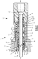
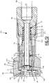
- a fluid connection 1 comprises a female fluid connection element 11 and a male fluid connection element 2 .
- the male coupling element 2 is a brass or copper tube.
- the male connector element 2 comprises a front end 4.
- the male connector element 2 is preferably tubular, that is to say it comprises an outer radial surface 3 of longitudinally constant diameter along the axis X2, at least for a longitudinal part of the male coupling element 2 extending from its front end 4 and intended to be fitted into the female coupling element 11.
- the male coupling element also comprises a channel internal.
- the tubular shape of the male coupling element 2 is advantageously coaxial with the axis X2.
- the male coupling element 2 is a copper or brass tube with a circular cross section.
- the internal channel of the male coupling element 2 is fluidically connected, at its rear end, to a reservoir of fluid under pressure, for example at 20 bars, for example a refrigerant fluid.
- the male connector element 2 forms an inlet of the tank and is used to fill the tank with this fluid under pressure, coming from the female connector element 11. Once the filling has been carried out, the male connector element 2 is crushed and welded and the front end 4 is cut.
- the female coupling element 11 comprises a female body 21, preferably comprising a front body 22, a rear body 24 and an intermediate body 23, which are tubular and coaxial with the longitudinal axis X11.
- the front body 22 and the rear body 24 are fixedly fixed to each other.
- the rear body 24 is designed to be connected to a pipe 99, shown in broken lines on the figure 1 , also coaxial with the longitudinal axis X11.
- the female body 21 delimits an internal channel 29 in communication with the pipe 99.
- the front body 22, the intermediate body 23 and the rear body 24 each delimit, along the longitudinal axis X11, a successive part of the internal channel 29.
- the front body 22 comprises a mouth 25, which extends axially at a front end of the front body 22.
- the internal channel 29 is shaped to receive the male coupling element 2 by fitting therein.
- the male connector element 2 can be introduced into the internal channel 29, via the front end 4, introduced into the female body 21 via the mouth 25.
- the female coupling element 11 is shaped so that the longitudinal axes X2 and X11 of the fluidic coupling 1 are coaxial.
- the front body 22 comprises a latch housing 26, which extends radially to the longitudinal axis X11 and which opens onto an outer radial surface of the front body 22, in a direction radial with respect to the longitudinal axis X11 and which is blind in the opposite radial direction.
- the intermediate body 23 comprises, at its front end, an internal surface 30 inclined in bevel, which diverges forwards.
- the inclined internal surface 30 is of conical shape centered on the longitudinal axis X11.
- the intermediate body 23 forms an internal radial covering surface 14, of constant diameter along the longitudinal axis X11.
- the female connector element 11 comprises a lock 41 received in the lock housing 26.
- the lock 41 is capable of locking the male connector element 2, in particular if the male element is a copper or brass tube.
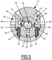
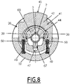
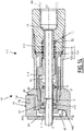
- the latch 41 is slidably mounted in the front body 22, transversely with respect to the longitudinal axis X11, in particular radially with respect to the longitudinal axis X11, between a retaining position of the male coupling element 2 in the female body 21, shown on the figure 3 , 7 and 8 , and a release position, shown on the figure 1 , 2 , 4 and 5 , in which the lock 41 does not oppose the withdrawal of the male coupling element 2 from the female body 21 nor the introduction of the male coupling element 2 into the female body 21.
- the lock 41 In the release position, the lock 41 is preferentially pushed further into the female body 21 than in the retaining position. In particular, in the release position, the latch 41 allows the movement of the male coupling element 2 in the female body 21, at least longitudinally.
- a radial axis R11 is defined, which is radial with respect to the longitudinal axis X11. In the present example, the lock 41 is movable along the radial axis R11 relative to the female body 21.
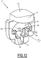
- Lock 41 shown alone on the figure 12 , comprises an actuating part 42, with an outer face 43, on which an operator can act.
- the outer face 43 is therefore accessible from the outside of the female body 21, in particular from the outside of the lock housing 26 with the actuating part 42 disposed at the level of the radial opening of the lock housing 26. In the position of retained, the outer face 43 of the latch 41 is farther from the longitudinal axis X11 than in the release position.
- the latch 41 also comprises an opening 44, which passes longitudinally through the latch 41 and which is intended to receive the male connection element 2.
- the male connection element 2 then passes through the latch 41 via the opening 44.
- This opening 44 delimits two locking surfaces 45a and 45b.
- the locking surfaces 45a, 45b each delimit only a portion of the opening 44 around the axis X11.
- the two locking surfaces 45a and 45b are arranged on either side of the axis X11, preferably symmetrically with respect to a radial plane containing the radial axis R11, for example the cutting plane of the figure 1 .
- the two locking surfaces 45a and 45b are preferably flat surfaces.
- the locking surfaces 45a and 45b preferably form an angle ⁇ of 18° (degrees), where each locking surface 45a, 45b forms an angle of 9° with respect to a longitudinal direction X11' parallel to the axis longitudinal X11.
- the two locking surfaces 45a and 45b are inclined relative to each other.
- the locking surfaces 45a and 45b are arranged on either side of the radial axis R11.
- the passage of the opening 44 formed by the locking surfaces 45a, 45b is also V-shaped, that is to say that the passage forms a flared notch, the mouth of which, closer of the actuating part 42 that the bottom of the V-shaped passage, is wider than the bottom.
- the locking surfaces 45a and 45b converge away from the actuating part 42 and the radial outlet of the housing 26 in which the actuating part 42 is received.
- the locking surfaces 45a and 45b together form an angle ⁇ of 30°, where each locking surface 45a, 45b forms an angle of 15° each with respect to the radial axis R11.
- the opening 44 also delimits two abutment surfaces 46, which are orthoradial to the longitudinal axis X11.
- the two abutment surfaces 46 are perpendicular to the radial axis R11.
- the two abutment surfaces 46 extend in the same plane parallel to the orthoradial plane of the figure 9 or in a plane perpendicular to the plane of the figure 1 .
- the abutment surfaces 46 each extend from one of the locking surfaces 45a, 45b, being symmetrical with respect to a plane comprising the radial axis R11 and the longitudinal axis X11.
- the abutment surfaces 46 are oriented towards the actuating part 42 of the lock 41.
- the latch 41 also delimits two retaining surfaces 39, which are orthoradial to the longitudinal axis X11.
- the retaining surfaces 39 extend in the same plane parallel to the orthoradial plane of the figure 9 .
- the retaining surfaces 39 extend respectively behind each of the abutment surfaces 46, being symmetrical with respect to the plane comprising the radial axis R11 and the longitudinal axis X11.
- An axial surface connects each of the abutment surfaces 46 and the retaining surface 39 which is axially aligned thereto.
- the retaining surfaces 39 are farther from the outer face 43 of the lock 41 than the abutment surfaces 46.
- the opening 44 also delimits a longitudinal indexing groove 47, which opens into the V-shaped passage formed by the locking surfaces 45a and 45b.
- the longitudinal indexing groove 47 interconnects the locking surfaces 45a and 45b by being traversed by the plane comprising the radial axis R11 and the longitudinal axis X11.
- the female coupling element 11 comprises two helical compression springs 49, which constitute elastic means which push the latch 41 towards its retaining position, resting on the female body 21.
- the latch 41 advantageously comprises two external transverse housings 48, which extend parallel to the sliding axis of the lock 41, here the radial axis R11.
- the front body 22 advantageously comprises two external transverse housings 27, which extend parallel to the axis of sliding of the lock 41, and are arranged opposite the outer transverse housings 48.
- Each spring 49 is housed, at one transverse end of the spring 49, in one of the outer transverse housings 48 and, at an opposite transverse end of the spring 49, in one of the external transverse housings 27.
- the elastic return means being in the form of two springs 49, they thus offer an elastic return force compatible with the desired locking force for the male coupling element 2.
- the female coupling element 11 comprises a pusher ring 51, which constitutes a preferred example of a pusher.
- the push ring 51 is advantageously of generally tubular shape coaxial with the longitudinal axis X11.
- the push ring 51 is movably mounted inside the intermediate body 23, in the internal channel 29 of the female body 21.
- the push ring 51 slides longitudinally relative to the female body 21 but is radially secured to the female body 21. It is advantageously provided that the intermediate body 23 supports and guides the push ring 51 in this sliding, the push ring 51 being received inside the intermediate body 23.
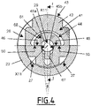
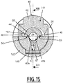
- the intermediate body 23 comprises three elongated housings 19, which each house an actuating ball 18. As shown in the figure 6 , three actuating balls 18, housed in three respective elongated housings 19, are advantageously provided. Each elongated housing 19 passes radially through the intermediate body 23.
- the elongated housings 19 are advantageously distributed in a regular manner around the longitudinal axis X11, being all arranged at the same longitudinal level on the longitudinal axis X11.
- elongated is meant that each elongated housing 19 is elongated in the longitudinal direction. In the orthoradial direction, each elongated housing 19 preferably has a width adjusted to the diameter of the actuating ball 18 that this elongated housing 19 receives.
- the female coupling element 11 comprises two auxiliary O-ring seals 32 and 33, which are housed in two respective internal grooves 16 and 17 of the female body 21.
- the auxiliary seals 32 and 33 as well as the grooves 16 and 17 are advantageously coaxial with the longitudinal axis X11.
- the auxiliary seal 32 and the groove 16 are advantageously provided on the intermediate body 23.
- the auxiliary seal 33 and the groove 17 are advantageously provided on the rear body 24.
- the two auxiliary seals 32 and 33 are arranged longitudinally on either side of the elongated housings 19, the auxiliary seal 32 being arranged at the front, while the auxiliary seal 33 is arranged at the rear.
- the auxiliary seals 32 and 33 are interposed radially between the female body 21 and the pusher 51, in order to ensure sealing between the female body 21 and the pusher 51.
- the auxiliary seals 32 and 33 are designed to ensure sealing between the push ring 51 and the female body 21 regardless of the longitudinal position of the push ring 51 in the female body 21.
- the push ring 51 comprises a front flange 52 and a rear flange 53 which delimit, longitudinally between them, a volume 54 for partially receiving the actuating balls 18, the volume 54 being advantageously of annular shape.
- the front flange 52 comprises, at the rear, a contact surface 58 intended to come into contact with the actuating balls 18 during a rearward movement of the push ring 51, in order to drive the balls of actuation 18 backwards
- the actuation balls 18 therefore cooperate longitudinally with the push ring 51.
- the contact surface 58 delimits the volume 54.
- the female coupling element 11 also comprises a spring 71, which is longitudinally interposed between the rear body 24 and the pusher ring 51.
- the spring 71 pushes the pusher ring 51 longitudinally towards the mouth 25 of the front body 22, that is that is to say towards a forward position of the push ring 51 with respect to the female body 21.
- the push ring 51 is in the forward position.
- the rear flange 53 advantageously provides axial support for the spring 71.
- the push ring 51 delimits a front counterbore 55.
- the front counterbore 55 is longitudinally delimited, towards the rear, by a longitudinal shoulder 56 of the push ring 51.
- the front counterbore 55 emerges, towards the front, outside of the push ring 51, at a front end 12 of the push ring 51.
- the female coupling element 11 comprises a memory ring 61.
- the memory ring 61 is advantageously of generally tubular shape coaxial with the longitudinal axis X11.
- the memory ring 61 is mounted radially between the front body 22 and the intermediate body 23, that is to say that the front body 22 surrounds the memory ring 61, while the memory ring 61 surrounds the intermediate body 23.
- front 22 also surrounds the intermediate body 23.
- the push ring 51 and the memory ring 61 are arranged radially on either side of the intermediate body 23.
- the memory ring 61 is mounted with the possibility of longitudinal sliding relative to the female body 21, but is radially integral with the body female 21.
- This memory ring 61 comprises an outer ring 62 and an inner annular ring 63.
- the inner annular ring 63 is mounted floating in the outer ring 62.
- the inner annular ring 63 can slide longitudinally with respect to the outer ring 62, and pivot about the longitudinal axis X11, even if these movements are not necessary for the operation of the female coupling element 11.
- the female coupling element 11 comprises a spring 72 which, relative to the female body 21, pushes the memory ring 61 longitudinally in the direction of the mouth 25 of the front body 22, into the opening 44 of the lock 41.
- the spring 72 bears axially, parallel to the longitudinal axis X11, on the intermediate body 23 and on a rear face 64 of the outer ring 62 of the memory ring 61.
- the elastic force exerted by spring 72 is less than the elastic force exerted by spring 71.
- the outer ring 62 includes an inner groove 65 device.
- the outer ring 62 also comprises a mounting orifice 66, advantageously single, which opens into the inner groove 65 and at the level of the outer surface of the outer ring. 62.
- the orifice 66 passes radially through the outer ring 62.
- the internal groove 65 delimits a volume for partial reception of the actuating balls 18.
- the diameter of the orifice 66 is slightly greater than the diameter of each actuating ball 18.
- the actuating balls 18 are intended to come into contact with a contact surface 70 of the internal groove 65, at the rear of said internal groove 65.
- the actuating balls 18 therefore cooperate longitudinally with the memory ring 61.
- the contact surfaces 58 and 70 have substantially the same inclination relative to the longitudinal axis X11, preferably an oblique inclination relative to the longitudinal axis X11.
- the outer ring 62 of the memory ring 61 comprises an indexing tongue 67 and a half-crown 68 which extend forward from the outer ring 62.
- the indexing tongue 67 and the half-crown 68 are at the front end of the memory ring 61.
- the annular inner ring 63 cooperates longitudinally with the outer ring 62 at the level of the indexing tongue 67 and at the level of the half-ring 68, either by being floating, or by being fixedly integral.
- the memory ring 61 comprises abutment surfaces 50 orthoradial with respect to the longitudinal axis X11, which, in the present example, extend in the same orthoradial plane parallel to the orthoradial plane of the figure 9 .
- the two abutment surfaces 50 are perpendicular to the radial axis R11.
- the abutment surfaces 50 are formed by the half-ring 68.
- the indexing tongue 67 is introduced into the longitudinal indexing groove 47, which guides the sliding of the lock 41 along the radial axis R11 and prevents the rotation of the lock 41 and of the memory ring 61 one by one. relative to each other around the longitudinal axis X11.
- the half-crown 68 is engaged in the opening 44.
- the female coupling element 11 comprises an annular adjustment ring 81, preferably coaxial with the longitudinal axis X11, which is housed radially between the push ring 51 and the intermediate body 23.
- the adjustment ring 81 slides longitudinally in the intermediate body 23, being for this guided by the internal radial surface of cover 14.
- the female coupling element 11 comprises a spring 73, which pushes the adjustment ring 81 longitudinally towards the mouth 25 of the front body 22.
- the spring 73 is interposed between the intermediate body 23 and a rear face 82 of the adjusting ring. adjustment 81.
- the female coupling element 11 comprises a main seal 31 and defines a main housing 15 for this main seal 31.
- the main seal 31 is for example an O-ring made of ethylene propylene.
- the main seal 31 is advantageously coaxial with the longitudinal axis X11 and is mounted in the main housing 15.
- a front face of the adjustment ring 81 forms a rear axial wall 83 of the main housing 15.
- the rear face of the annular inner ring 63 of the memory ring 61 forms a front axial wall 69 of the main housing 15.
- the main housing 15 of the main seal 31 is therefore delimited longitudinally by the memory ring 61 on the one hand and the ring of adjustment 81 on the other hand. In the uncoupled configuration, the memory ring 61 forms an internal radial wall of the main housing.
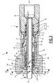
- the female coupling element 11 is designed to adopt a mated configuration, shown in the picture 3 and an uncoupled configuration, shown in the figure 1 .
- These coupled and uncoupled configurations are element specific female connector 11, regardless of the position of the male connector element 2 relative to the female connector element 11.
- These coupled and uncoupled configurations reflect a relative positioning of the different parts of the female connector element 11, in particular, the female body 21, the main seal 31, the lock 41, the push ring 51 and the memory ring 61.
- the female coupling element 11 is in an intermediate configuration obtained on coupling, that is to say between the uncoupled configuration and the coupled configuration.
- the spring 72 pushes the outer ring 62 of the memory ring 61 forward relative to the female body 21, to an advanced position in which the outer ring 62 is abutting forwards against the front body 22.
- the push ring 51 is pushed back into the forward position relative to the female body 21, in abutment forwards against the annular inner ring 63 of the memory ring 61.
- the main seal 31 is placed around an external radial surface 57 at the level of a part of longitudinally constant external diameter of the push ring 51.
- main seal 31 is stretched around the push ring 51.
- the push ring 51 is interposed radially between the front counterbore 55 and the main seal 31.
- the main seal 31 is longitudinally offset, forward, relative to the intermediate body 23 of the female body 21, being disposed axially beyond the front end of the intermediate body 23.
- each actuation ball 18 is confined in its respective elongated housing 19, between a front end of the elongated housing 19 and a rear surface of the internal groove 65 of the memory ring 61.
- the abutment surfaces 46 of the latch 41 cooperate in a transverse direction with the abutment surfaces 50 of the memory ring 61, while the memory ring 61 is in the advanced position.
- the abutment surfaces 46 and 50 are at the same level along the longitudinal axis X11 so as to be in transverse support two by two.
- the memory ring 61 maintains the lock 41 in release position in the female body 21, that is to say a depressed position, against the action of the two springs 49.
- the locking surfaces 45a and 45b are further from the longitudinal axis X11 along the radial axis R11 only in the retained position so as to allow the movement of the male coupling element 2 in the internal channel 29.
- the adjustment ring 81 is pushed forwards, in contact with the main seal 31, by the spring 73.
- the spring 73 bears on the intermediate body 23.
- adjustment ring 81 is then radially surrounded by inclined inner surface 30, being axially at its level.
- the female coupling element 11 is coupled with the male coupling element 2, as shown in order on the figure 1 , 2 and 3 . As explained below, this coupling is automatic.
- the front end 4 of the male coupling element 2 is introduced into the mouth 25 of the front body 22 and is engaged in the memory ring 61, then in the front counterbore 55 delimited by the push ring 51 , while the push ring 51 is in the forward position.
- the longitudinal axes X2 and X11 become substantially coaxial.
- the push ring 51 is interposed radially between the front end 4 of the male coupling element 2 and the main seal 31, the push ring 51 having the function of an interface ring to protect the main seal 31 from possible burrs or abrasive irregularities which could be formed at the front end 4.
- the push ring 51 protects the main seal 31 against possible burrs at the front end 4 of the male coupling element 2 introduced into the female coupling element 11.
- the fitting movement of the male connector element 2 in the female connector element 11 continues, the male connector element 2 thus driving the push ring 51 towards the rear of the female connector element 11, against the action of the spring 71.
- the female coupling element 11 adopts a intermediate coupling configuration between the coupled configuration and the uncoupled configuration.
- the push ring 51 shifts longitudinally with respect to the main seal 31, towards the rear of the male coupling element 2. By this longitudinal shift of the push ring 51, the main seal 31 is directly in radial view of a reception volume of the male coupling element 2 in the female coupling element 11.
- the main seal 31 shrinks radially around the male coupling element 2 and comes into radial contact internal with the outer radial surface 3 and at a distance from the front end 4, in the direction of the rear of the male coupling element 2, the distance at the front end 4 corresponding to the depth of the front counterbore 55 along the longitudinal axis X11.
- the main seal 31 thus comes into contact with the male coupling element 2 at an axial place where the risk of abrasive burrs is less significant than at the front end 4, which preserves the integrity of the seal. main seal 31.
- a longitudinal distance L1 measured parallel to the longitudinal axis X11 in the uncoupled configuration, between the front end 12 of the push ring 51 and the front end of the adjustment ring 81 forming the rear axial wall 83 of the main housing 15, is less than or equal to a longitudinal distance L2, measured parallel to the longitudinal axis X11 in the uncoupled configuration, between the balls of actuation 18, in rear abutment against the internal groove 65, and the contact surface 58 of the front flange 52.
- the backward movement of the pusher ring 51 leads to the actuating balls 18 being placed in axial interposition between the respective contact surfaces 58 and 70 of the pusher ring 51 and of the memory ring 61, so that, on this bringing into contact of the actuating balls 18 with the contact surfaces 58 and 70, the push ring 51 becomes axially integral with the memory ring 61 in its rearward movement of the female body 21.
- the actuating balls 18 form means transmission of the recoil movement of the pusher ring 51 to the memory ring 61, to move the memory ring 61 to a retracted position of the memory ring.
- the memory ring 61 is in the retracted position.
- the actuating balls 18 transmit the recoil movement of the pusher ring 51 to the memory ring 61 in a small radial space and facilitate the mounting of the memory rings 61 and pusher 51 on either side of the intermediate body 23 of the female body 21.
- Front flange 52, elongated housings 19 and internal groove 65 are configured to provide push ring 51 with longitudinal movement relative to memory ring 61 from the uncoupled configuration.
- a movement sequence is obtained according to which the pusher ring 51 is first moved backwards, while the memory ring 61 remains in the advanced position, the displacement of the memory ring 61 only occurring secondarily.
- the displacement of the memory ring 61 rearward relative to the female body 21 drives the main seal 31 rearward, via the front axial wall 69 formed on the annular inner ring 63.
- the seal main seal 31 then comes axially at the level of the inclined inner surface 30 then of the inner radial surface 14 so as to be radially surrounded and clamped by the intermediate body 23, which causes a slight radial flattening of the main seal 31, as it moves rearward.
- the annular inner ring 63 then engages partially in the intermediate body 23. Under the action of the memory ring 61, the main seal 31 pushes the adjustment ring 81 backwards against the spring. 73, so that the adjustment ring 81 is axially offset rearward relative to the inclined internal surface 30.
- the adjustment ring 81 is then radially surrounded by the internal radial surface of cover 14 on all its length.
- the adjustment ring 81 accommodates the axial length of the main housing 15 allocated to the main seal 31 by moving rearwardly, against its spring 73, as can be seen by comparing the figure 2 and 3 .
- the main housing 15 of the female coupling element 11 is therefore variable both in dimensions and in position in the female body 21 between the uncoupled configuration and the coupled configuration of the female coupling element 11.
- the main seal 31 ensures a sealing between the male coupling element 2 and the female body 21 of the female coupling element 11.
- the memory ring 61 In this retracted position, the memory ring 61 thus allows the movement of the lock 41 towards its retaining position under the action of the springs 49. In the coupled configuration, the memory ring 61 is in the retracted position and the lock 41 is in the retaining position.
- the retracted position of the memory ring 61 is obtained when the push ring 51 is in a rear position relative to the female body 21, parallel to the longitudinal axis X11, as shown in the picture 3 .
- the push ring 51 in its movement to its rear position drives the memory ring 61 to its rear position.
- the push ring 51 is in rear abutment against the memory ring 61 via the actuation balls 18.
- the push ring 51 is in the rear position.
- the locking surfaces 45a and 45b are in a position of cooperation with the male coupling element 2, in particular with its external radial surface 3. Each locking surface 45a, 45b cooperates locally with the outer radial surface 3.
- the lock 41 thus exerts a longitudinal retention of the male coupling element 2 with respect to the lock 41, in the opening 44. Due to their particular orientation described above, the locking surfaces 45a and 45b form a wedge for retaining the male coupling element 2 in the female body 21 both along the radial axis R11 and along the longitudinal axis X11.
- the locking surfaces 45a and 45b are anchored in the male coupling element 2 in particular when the male coupling element 2 is made of copper or brass.
- the two retaining surfaces 39 of the latch 41 are opposite the abutment surfaces 50 of the memory ring 61, in the transverse direction.
- the retaining surfaces 39 of the lock are transversely at a distance from the abutment surfaces 50 of the memory ring 61, the lock 41 coming into transverse abutment against the male coupling element 2 via the locking surfaces 45a, 45b.
- the possible radial abutment of the latch 41 on the memory ring 61 makes it possible to limit the deformation of the male coupling element 2 by the locking surfaces 45a, 45b.
- a longitudinal distance L3 is defined, measured along the longitudinal axis X11, which is the distance traveled by the front axial wall 69 with respect to the intermediate body 23, for the covering of the main seal 31 by the internal radial surface of covering 14 of the female body 21.
- it is the longitudinal distance traveled backwards by the memory ring 61, in particular by the annular inner ring 63, from the advanced position, until the front axial wall 69 has reached the front end of the internal radial covering surface 14, at the junction between the internal radial covering surface 14 and the inclined internal surface 30.
- this longitudinal distance L3 can be equal to the distance traveled by the memory ring 61, in particular the inner annular ring 63, between the advanced position and the retracted position, relative to the intermediate body 23.
- This longitudinal distance L3 is preferred ielment equal to a longitudinal distance, measured along the longitudinal axis X11 between, on the one hand, the front axial wall 69 of the main housing 15, formed by the memory ring 61, and, on the other hand, the front end of the internal radial covering surface 14 of the intermediate body 23, when the female coupling element 11 is in the uncoupled configuration.
- a longitudinal distance L4 is defined, measured along the longitudinal axis X11, which is the longitudinal engagement length between the abutment surfaces 46 of the latch 41 and the abutment surfaces 50 of the memory ring 61 in the uncoupled configuration.
- the operator can release the male connector element 2, which is fitted and locked in the female connector element 11.
- an assembly comprising the memory ring 61, the actuating balls 18, the push ring 51 and the male coupling element 2 is pushed forwards relative to the female body 21, until the lock 41 comes to abutment forward against the front body 22.
- the axial play of lock 41 is thus taken up in the lock housing 26 formed in the female body 21.
- the locking surfaces 45a and 45b of the lock 41 are anchored in the outer radial surface 3 of the element male connector 2 and maintain the male connector element 2 with respect to the lock 41, therefore with respect to the female body 21, along the longitudinal axis X11.
- the locking surfaces 45a and 45b of the lock 41 are brought closer to the longitudinal axis X11, so as to extend partially into the reception volume of the male coupling element 2 in the female coupling element 11 and to cooperate with the male coupling element 2.
- the filling of the tank can then take place from the pipe 99, successively through the part of the internal channel 29 formed by the rear body 24, of the pusher 51 and the male coupling element 2, according to an arrow F3 shown on the picture 3 .
- the setting in coupled configuration is automatic, since the longitudinal movement of introduction of the male coupling element 2 into the female body 21 automatically causes the locking of the male coupling element 2 by the lock 41, by displacement of the memory ring 61.
- the coupled position can easily be identified by the operator, visually, since the retaining position of the lock 41, here less depressed than the release position of the lock 41, is visible from the outside of the connection 1.
- the female coupling element 11 defines, from the mouth 25, a volume of reception of the male coupling element 2 of reduced longitudinal dimension, in particular with respect to EP1916464 .
- the main seal 31 moving with the memory ring 61, the longitudinal distance over which the main seal scrapes the outer radial surface 3 of the male coupling element 2 is therefore relatively small.
- the operator actuates the lock 41 so as to move into the release position against the springs 49, that is to say, here, by pressing on the outer face 43 ..
- the movement of the lock 41 against the springs 49 is limited by the coming into abutment of the actuating part 42 of the lock 41 against the front body 22 along the axis R11.
- the lock 41 being in the release position, the locking surfaces 45a, 45b have left the contact of the male coupling element 2 and have been moved out of the reception volume of the male coupling element 2 in the element female connector 11, so that said male connector element 2 can be extracted from the female connector element 11, being moved backwards along the longitudinal axis X11.
- the push ring 51 follows the withdrawal movement of the male coupling element 2 and is inserted radially between the main seal 31 and the central longitudinal axis X11.
- the outer radial surface 57 forms an outer stretching surface 59, which has a beveled shape, converging forwards, in order to gradually stretch the gasket. main sealing 31 around the push ring 51 during the movement of the push ring 51 towards the forward position.
- the memory ring 61 Under the action of the spring 72, the memory ring 61 is pushed forwards until it comes to a stop before against the female body 21, that is to say until it comes into the advanced position. Once this position has been reached by the memory ring 61, the abutment surfaces 50 of the memory ring 61 are opposite the abutment surfaces 46 of the lock along the radial axis R11.
- the latch 41 When the operator then releases the latch 41, the latch 41 is pushed back by the springs 49.
- the latch 41 is held in the release position, here the depressed position, by cooperation of the abutment surfaces 46 of the latch 41 with the abutment surfaces 50 of the memory ring 61.
- the push ring 51 is in the front position and extends close to the mouth 25, in an admission volume of the male coupling element 2 in the female body 21, if the we want to proceed to a coupling again.
- the uncoupled configuration shown on the figure 1 is reached. More generally, the female coupling element 11 is ready for another automatic coupling.
- abutment surfaces 46 and 50 as well as retaining surfaces 39, which are planar here and cooperate together in a surface manner in the transverse direction, it is possible to provide a point or linear cooperation in the direction transverse to achieve the same effects.
- the front axial wall 69 and/or the rear axial wall 83 are inclined with respect to a plane orthogonal to the longitudinal axis X11.
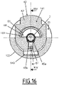
- a second embodiment of a fluid connection 101 is shown in the figures 13 to 17 .
- This fluid connection 101 is identical to the fluid connection 1 shown on the figures 1 to 12 , except for the differences shown in the figures and described below.
- the same vocabulary is used for both embodiments.
- Identical features are identified by the same reference sign, for both embodiments.
- the different characteristics but ensuring the same function are identified by a reference sign whose value is increased by 100 compared to the first embodiment.
- the pusher ring 151 is fixedly secured to the memory ring 161.
- the pusher ring 151 and the memory ring 161 have been represented as forming a piece of one piece.
- the push ring 151 and the memory ring 161 can be fixedly integral, forming a set of several parts fixedly integral with each other.
- a single spring 172 pushes the integral assembly comprising the memory ring 161 and push ring 151.
- the memory ring 161 and the push ring 151 are connected by radially crossing the intermediate body 123, at the level of one or more elongated housings 119, provided radially through said intermediate body 123.
- the push ring 151 therefore does not have the possibility of movement relative to the memory ring 161, along the longitudinal axis X11. In the advanced position of the memory ring 161, the push ring 51 is in the forward position; in the retracted position of the memory ring 161, the push ring 51 is in the rear position.
- the longitudinal shoulder 156 of the push ring 151 which cooperates with the male coupling element 2 and by which the male coupling element 2 pushes the push ring 151 and the memory ring 161, is arranged at the front end 112 of the push ring 151.
- the main seal 31 is housed in a main housing 115 which is made in the intermediate body 123 of the female body 121.
- the main housing 115 of the seal main 31 is therefore fixed relative to female body 121.
- push ring 151 does not act as an interface between front end 4 of male coupling element 2 and main seal 31.
- the lock 141 is formed in one piece with the elastic means which push the lock back into the retaining position.
- the elastic means are formed by a flexible portion 149 of the lock 141, said flexible portion resting on the front body 122 belonging to the female body 121.
- the memory ring 161 is integral transversely with the female body 121 and movable along the longitudinal axis X11 in the female body 121 between an advanced position, in which the memory ring 161 cooperates with the lock 141 radially to the longitudinal axis X11, and maintains thus the lock 141 in the release position, and a retracted position, in which the memory ring 161 allows the movement of the lock 141 towards its retaining position, the pusher 151 driving the memory ring 161 towards the retracted position when the pusher 151 is moved by the male coupling element 2 from the front position to the rear position during coupling.
- Spring 172 recalls memory ring 161 to its advanced position.
Claims (15)
- Fluidische Anschlussbuchse (11; 111), wobei die Anschlussbuchse (11; 111) entworfen ist, um eine gekoppelte Konfiguration (Fig. 3) und eine entkoppelte Konfiguration (Fig. 1) anzunehmen, und umfassend:- einen Buchsenkörper (21; 121), der einen internen Kanal (29) aufnimmt, der ausgelegt ist, um ein Steckanschlusselement (2) durch Einführen gemäß einer Längsachse (X11) der Anschlussbuchse (11; 111) zu empfangen;- eine Hauptdichtung (31), die ausgelegt ist, um radial mit dem Steckanschlusselement (2) in der gekoppelten Konfiguration zusammenzuarbeiten,- eine Verriegelung (41; 141), die mit einer Öffnung (44) durchbrochen ist, die entworfen ist, um vom Steckanschlusselement (2) gequert zu werden, wobei die Verriegelung (41; 141) gleitend in einer Verriegelungsaufnahme (26) montiert ist, die vom Buchsenkörper (21; 121) radial zur Längsachse (X11) zwischen einer Rückhalteposition, in der die Verriegelung (41; 141) mit einer äußeren radialen Oberfläche (3) des Steckanschlusselements (2) zusammenarbeitet und sich dem Rückzug des Steckanschlusselements (2) aus dem Buchsenkörper (21; 121) widersetzt, und einer Freigabeposition, in der die Verriegelung (41; 141) die Bewegung des Steckanschlusselements (2) im Buchsenkörper (21; 121) ermöglicht, mündet; in der gekoppelten Konfiguration befindet sich die Verriegelung (41; 141) in der Rückhalteposition;- elastische Mittel (49; 149), die die Verriegelung (41; 141) hin zu ihrer Rückhalteposition rückstellen, und- einen Knopf (51; 151), der zwischen einem inneren Kanal (29) des Buchsenkörpers (21; 121) gemäß der Längsachse (X11) zwischen einer vorderen Position und einer hinteren Position beweglich ist,- einen Speicherring (61; 161), der fest mit dem Buchsenkörper radial zur Längsachse (X11) verbunden und gemäß der Längsachse (X11) im Buchsenkörper (21; 121) beweglich ist, zwischen- einer vorgeschobenen Position, in der der Speicherring (61; 161) mit der Verriegelung (41; 141) radial zur Längsachse (X11) zusammenarbeitet und somit die Verriegelung (41; 141) in der Freigabeposition hält, und- einer zurückgezogenen Position, in der der Speicherring (61; 161) die Verschiebung der Verriegelung (41; 141) in ihre Rückhalteposition ermöglicht, wobei der Knopf (51; 151) ausgelegt ist, um den Speicherring (61; 161) bis in eine zurückgezogene Position anzutreiben, wenn sich der Knopf von der vorderen Position in die hintere Position verschiebt; und- eine erste Feder (72; 172), die den Speicherring (61; 161) hin zu seiner vorgeschobenen Position rückstellt, oder, in der entkoppelten Position, sich der Speicherring (61; 161) in der vorgeschobenen Position befindet.
- Anschlussbuchse (11; 111) nach Anspruch 1, wobei die Verriegelung (41; 141) und der Speicherring (61; 161) jeweilige Anschlagoberflächen (46, 50) umfassen, die orthoradial mit Bezug auf die Längsachse (X11) sind, und wobei die Anschlagoberfläche (50) des Speicherrings (61; 161) und die Anschlagoberfläche (46) der Verriegelung (41; 141):- in der vorgeschobenen Position des Speicherrings (61; 161) in Kontakt sind, um die Verriegelung (41; 141) und der Freigabeposition zu halten, und- in der zurückgezogenen Position des Speicherrings (61; 161) mit Bezug aufeinander gemäß der Längsachse (X11) versetzt sind, um die Verschiebung der Verriegelung (41; 141) in ihre Rückhalteposition zu ermöglichen.
- Anschlussbuchse (11; 111) nach Anspruch 2, wobei die Anschlagoberfläche (46) der Verriegelung durch die Öffnung (44) der Verriegelung (41; 141) begrenzt ist.
- Anschlussbuchse (11; 111) nach einem der Ansprüche 2 oder 3, wobei in der Rückhalteposition der Verriegelung (41; 141) sich die Anschlagoberfläche (50) des Speicherrings (61; 161) gegenüber einer Rückhalteoberfläche (39) der Verriegelung (41; 141) radial mit Bezug auf die Längsachse (X11) befindet.
- Anschlussbuchse (11; 111) nach einem der vorhergehenden Ansprüche, wobei die Verriegelung (41; 141) zwei Verriegelungsoberflächen (45a, 45b) umfasst, die die Abschnitte der Öffnung (44) begrenzen, und die ausgelegt sind, mit dem Steckanschlusselement (2) in der Rückhalteposition der Verriegelung (41; 141) zusammenzuarbeiten, die zwei Verriegelungsoberflächen (45a, 45b) symmetrisch mit Bezug auf eine radiale Ebene mit Bezug auf die Längsachse (X11) sind und die zwei Verriegelungsoberflächen (45a, 45b) mit Bezug aufeinander geneigt sind und gegenüber der radialen Einmündung der Verriegelungsaufnahme (26) in einer Schnittebene orthogonal zur Längsachse (X11) zusammenlaufen und die zwei Verriegelungsoberflächen (45a, 45b) queren.
- Anschlussbuchse (11; 111) nach Anspruch 5, wobei die zwei Verriegelungsoberflächen (45a, 45b) mit Bezug aufeinander geneigt sind und hin zur Hinterseite der Anschlussbuchse (11; 111) in einer Schnittebene orthoradial zur Längsachse (X11) zusammenlaufen und die zwei Verriegelungsoberflächen (45a, 45b) queren.
- Anschlussbuchse (11; 111) nach einem der vorhergehenden Ansprüche, wobei der Knopf (51) über eine Bewegungsmöglichkeit mit Bezug auf den Speicherring (61) gemäß der Längsachse (X11) verfügt.
- Anschlussbuchse (11; 111) nach einem der vorhergehenden Ansprüche, wobei- der Speicherring (61; 161) und der Knopf (51; 151) radial auf beiden Seiten des Buchsenkörpers (21; 121) angeordnet sind;- der Buchsenkörper eine längliche Aufnahme (19) umfasst, die radial querend ist,- zwei Dichtungen (32, 33), angeordnet auf beiden Seiten der länglichen Aufnahme (19), entlang der Längsachse (X11) radial zwischen dem Knopf (51; 151) und den Buchsenkörper (21; 121) gestellt sind, und- die Anschlussbuchse (11; 111) mindestens ein Übertragungselement (18) umfasst, das in der länglichen Aufnahme (19) angeordnet ist, und das ausgelegt ist, um der Länge nach mit dem Speicherring (61) und mit dem Knopf (51) zusammenzuarbeiten, so dass der Knopf (51, 151) ausgelegt ist, um den Speicherring (61; 161) in die zurückgezogene Position mit Hilfe des Übertragungselements anzutreiben.
- Anschlussbuchse (11) nach Anspruch 8, wobei jedes Übertragungselement (18) eine Betätigungskugel umfasst.
- Anschlussbuchse (11; 51) nach einem der vorhergehenden Ansprüche, wobei der Knopf (51):- eine vordere Senkung (55) zur Aufnahme eines vorderen Endes (4) des Steckanschlusselements (2) begrenzt;- in der vorderen Position und in der entkoppelten Konfiguration der Anschlussbuchse (11) radial zwischen die vordere Senkung (55) und die Hauptdichtung (31) gestellt ist; und- beweglich gemäß der Längsachse (X11) mit Bezug auf den Buchsenkörper (21) gegenüber einer zweiten Feder (71) der Anschlussbuchse (11) bis in eine Position ist, in der der Knopf (51) der Länge nach mit Bezug auf die Hauptdichtung (31) versetzt ist.
- Anschlussbuchse (11) nach einem der vorhergehenden Ansprüche, wobei- die Anschlussbuchse (11) eine Hauptaufnahme (15) umfasst, die die Hauptdichtung (31) aufnimmt;- des Buchsenkörper (21) einen Zwischenkörper (23) umfasst, um den der Speicherring (61) montiert ist; und- der Speicherring (61) eine vordere axiale Wand (69) der Hauptaufnahme (15) bildet.
- Anschlussbuchse (11) nach Anspruch 11, wobei- in der entkoppelten Konfiguration die Hauptdichtung (31) der Länge nach mit Bezug auf den Zwischenkörper (23) versetzt ist; und- in der gekoppelten Konfiguration eine innere radiale Abdeckoberfläche (14) des Zwischenkörpers (23) die Hauptdichtung (31) radial abdeckt.
- Anschlussbuchse (11; 111) nach einem der Ansprüche 11 oder 12, wobei die Anschlussbuchse (11) außerdem einen Einstellring (81) umfasst, der im Zwischenkörper (23) aufgenommen ist und eine hintere axiale Wand (83) der Hauptaufnahme (15) der Hauptdichtung (31) in der Buchse (11) bildet, wobei der Einstellring (81) beweglich mit Bezug auf den Zwischenkörper (23) gemäß der Längsachse (X11) ist und durch eine dritte Feder (73) in Richtung der Hauptdichtung (31) zurückgedrängt wird.
- Anschlussbuchse (11; 111) nach einem der vorhergehenden Ansprüche, wobei der Speicherring (61; 161) eine Indexierungslasche (67) umfasst, die in einer längs gerichteten Indexierungsnut (47) der Verriegelung (41; 141) eingegriffen ist, um den Speicherring (61; 161) und die Verriegelung (41; 141) in Rotation um die Längsachse (X11) zu verbinden.
- Fluidischer Anschluss (1; 101), umfassend ein Steckanschlusselement (2) sowie die Anschlussbuchse (11; 111 ) nach einem der vorhergehenden Ansprüche, wobei das Steckanschlusselement (2) ausgelegt ist, um der Länge nach gegen den Knopf (51; 151) in Anschlag zu kommen und den Knopf (51; 151) aus seiner vorderen Position in seine hintere Position zurückzustoßen, wobei die Verriegelung (41; 141) in der Rückhalteposition mit der externen radialen Oberfläche (3) des Steckanschlusselements (2) zusammenzuarbeitet, um sich dem Rückzug des Steckanschlusselements (2) aus dem Buchsenkörper (21; 121) entgegenzustellen, wobei die externe radiale Oberfläche (3) des Steckanschlusselements (2) einen konstanten längsgerichteten Durchmesser auf seinem gesamten Längsteil aufweist, der auf die Anschlussbuchse (11; 111) in der gekoppelten Konfiguration aufgesteckt ist.
Applications Claiming Priority (1)
| Application Number | Priority Date | Filing Date | Title |
|---|---|---|---|
| FR1873884A FR3090797B1 (fr) | 2018-12-21 | 2018-12-21 | Elément femelle de raccord et raccord fluidique comprenant un élément mâle de raccord ainsi que ledit élément femelle de raccord |
Publications (2)
| Publication Number | Publication Date |
|---|---|
| EP3670992A1 EP3670992A1 (de) | 2020-06-24 |
| EP3670992B1 true EP3670992B1 (de) | 2022-09-14 |
Family
ID=66867300
Family Applications (1)
| Application Number | Title | Priority Date | Filing Date |
|---|---|---|---|
| EP19218661.7A Active EP3670992B1 (de) | 2018-12-21 | 2019-12-20 | Anschlussbuchse und fluidanschluss, der ein steckanschlusselement sowie diese anschlussbuchse umfasst |
Country Status (6)
| Country | Link |
|---|---|
| US (1) | US11262009B2 (de) |
| EP (1) | EP3670992B1 (de) |
| JP (1) | JP2020101283A (de) |
| KR (1) | KR20200078380A (de) |
| CN (1) | CN111350897B (de) |
| FR (1) | FR3090797B1 (de) |
Families Citing this family (2)
| Publication number | Priority date | Publication date | Assignee | Title |
|---|---|---|---|---|
| FR3097565B1 (fr) * | 2019-06-19 | 2022-08-12 | Staubli Sa Ets | Machine textile, métier à tisser comportant une telle machine textile et procédés associés |
| KR20220000581A (ko) | 2020-06-26 | 2022-01-04 | 에스케이하이닉스 주식회사 | 반도체 장치 및 반도체 장치의 제조 방법 |
Family Cites Families (9)
| Publication number | Priority date | Publication date | Assignee | Title |
|---|---|---|---|---|
| FR1487324A (fr) | 1966-01-04 | 1967-07-07 | Staubli Freres & Cie | Dispositif de raccord rapide pour la jonction de canalisations et analogues |
| FR2461876A1 (fr) * | 1979-07-23 | 1981-02-06 | Staubli Sa Ets | Perfectionnements aux dispositifs de raccord rapide pour la jonction des canalisations |
| FR2640721B1 (fr) * | 1988-12-19 | 1991-02-01 | Legris Sa | Coupleur automatique pour circuit de fluide sous pression |
| FR2847330A1 (fr) * | 2002-11-19 | 2004-05-21 | Staubli Sa Ets | Raccord rapide pour la jonction amovible de deux canalisations |
| FR2865259B1 (fr) * | 2004-01-20 | 2006-04-21 | Staubli Sa Ets | Raccord rapide et procede de desacouplement des elements male et femelle d'un tel raccord |
| FR2907188B1 (fr) * | 2006-10-13 | 2010-10-08 | Staubli Sa Ets | Element femelle de raccord et raccord incorporant un tel element |
| IT1395157B1 (it) * | 2009-08-07 | 2012-09-05 | Stucchi Spa | Innesto rapido con dispositivo di sicurezza antisgancio |
| FR3061258B1 (fr) * | 2016-12-23 | 2019-05-31 | Staubli Faverges | Element femelle de raccord, destine a etre accouple avec un element male complementaire et raccord comprenant un tel element femelle |
| US10781957B2 (en) * | 2017-01-24 | 2020-09-22 | Staubli Faverges | Fluid coupling element and fluid-coupling comprising such an element |
-
2018
- 2018-12-21 FR FR1873884A patent/FR3090797B1/fr active Active
-
2019
- 2019-12-16 US US16/715,344 patent/US11262009B2/en active Active
- 2019-12-17 JP JP2019227069A patent/JP2020101283A/ja active Pending
- 2019-12-19 KR KR1020190171113A patent/KR20200078380A/ko unknown
- 2019-12-20 EP EP19218661.7A patent/EP3670992B1/de active Active
- 2019-12-20 CN CN201911329035.9A patent/CN111350897B/zh active Active
Also Published As
| Publication number | Publication date |
|---|---|
| US11262009B2 (en) | 2022-03-01 |
| JP2020101283A (ja) | 2020-07-02 |
| FR3090797B1 (fr) | 2021-01-22 |
| FR3090797A1 (fr) | 2020-06-26 |
| CN111350897B (zh) | 2023-04-21 |
| CN111350897A (zh) | 2020-06-30 |
| US20200200310A1 (en) | 2020-06-25 |
| KR20200078380A (ko) | 2020-07-01 |
| EP3670992A1 (de) | 2020-06-24 |
Similar Documents
| Publication | Publication Date | Title |
|---|---|---|
| EP2439440B1 (de) | Anschlussvorrichtung mit Verriegelung durch Gewindegriffe, und Anschluss, der eine solche Vorrichtung enthält | |
| EP2088358B1 (de) | Verbindungssteckerelement und Schnellverbindung, die ein solches Element beinhaltet | |
| EP1135643B1 (de) | Kugelkupplung | |
| EP2141402B1 (de) | Anschlusselement mit Haken und Anschluss, der mindestens ein solches Element umfasst | |
| EP1862720B1 (de) | Verbindungssteckerelement und Schnellverbindung, die ein solches Element beinhaltet | |
| EP2306061B1 (de) | Schnellkupplungsmuffe und Schnellkupplung mit solcher Schnellkupplungsmuffe | |
| EP3339710B1 (de) | Anschlussbuchse zum anschliessen eines entsprechendes steckerelements, und anschluss, der eine solche buchse umfasst | |
| FR2820489A1 (fr) | Dispositif de branchement d'alimentation pour un systeme a pression de fluide | |
| EP1862719A1 (de) | Verbindungselement mit Verriegelungsnut und ein solches Element integrierende Verbindung | |
| EP3670992B1 (de) | Anschlussbuchse und fluidanschluss, der ein steckanschlusselement sowie diese anschlussbuchse umfasst | |
| EP3220034B1 (de) | Kupplungselement für die verbindung von flüssigkeitsführenden bauteilen und kupplung mit einem solchen element. | |
| FR2756608A1 (fr) | Raccord rapide etanche | |
| EP3581836A1 (de) | Flüssigkeitskupplung | |
| FR3071301B1 (fr) | Coupe-circuit et installation de manutention de fluide sous pression comprenant un tel coupe-circuit | |
| EP3553363B1 (de) | Kupplungselement und kupplungsvorrichtung mit solchem kupplungselement | |
| EP3196526B1 (de) | Schnellkupplung für die lösbare verbindung von leitungen für fluide unter druck | |
| EP3798490B1 (de) | Fluidanschlusselement | |
| EP4166836A1 (de) | Schnellkupplung und verbindungsanordnung mit einer solchen schnellkupplung | |
| EP4306837A1 (de) | Anschlusselement für eine fluidverbindung an ein endgerät | |
| EP4336080A1 (de) | Schnellkupplungsbuchse | |
| FR2790057A1 (fr) | Coupleur a billes | |
| FR2843625A1 (fr) | Dispositif de branchement d'alimentation pour un systeme a pression de fluide | |
| FR2750753A1 (fr) | Vanne obturatrice a coulissement axial |
Legal Events
| Date | Code | Title | Description |
|---|---|---|---|
| PUAI | Public reference made under article 153(3) epc to a published international application that has entered the european phase |
Free format text: ORIGINAL CODE: 0009012 |
|
| STAA | Information on the status of an ep patent application or granted ep patent |
Free format text: STATUS: THE APPLICATION HAS BEEN PUBLISHED |
|
| AK | Designated contracting states |
Kind code of ref document: A1 Designated state(s): AL AT BE BG CH CY CZ DE DK EE ES FI FR GB GR HR HU IE IS IT LI LT LU LV MC MK MT NL NO PL PT RO RS SE SI SK SM TR |
|
| AX | Request for extension of the european patent |
Extension state: BA ME |
|
| STAA | Information on the status of an ep patent application or granted ep patent |
Free format text: STATUS: REQUEST FOR EXAMINATION WAS MADE |
|
| 17P | Request for examination filed |
Effective date: 20201127 |
|
| RBV | Designated contracting states (corrected) |
Designated state(s): AL AT BE BG CH CY CZ DE DK EE ES FI FR GB GR HR HU IE IS IT LI LT LU LV MC MK MT NL NO PL PT RO RS SE SI SK SM TR |
|
| GRAP | Despatch of communication of intention to grant a patent |
Free format text: ORIGINAL CODE: EPIDOSNIGR1 |
|
| STAA | Information on the status of an ep patent application or granted ep patent |
Free format text: STATUS: GRANT OF PATENT IS INTENDED |
|
| INTG | Intention to grant announced |
Effective date: 20220513 |
|
| GRAS | Grant fee paid |
Free format text: ORIGINAL CODE: EPIDOSNIGR3 |
|
| GRAA | (expected) grant |
Free format text: ORIGINAL CODE: 0009210 |
|
| STAA | Information on the status of an ep patent application or granted ep patent |
Free format text: STATUS: THE PATENT HAS BEEN GRANTED |
|
| AK | Designated contracting states |
Kind code of ref document: B1 Designated state(s): AL AT BE BG CH CY CZ DE DK EE ES FI FR GB GR HR HU IE IS IT LI LT LU LV MC MK MT NL NO PL PT RO RS SE SI SK SM TR |
|
| REG | Reference to a national code |
Ref country code: GB Ref legal event code: FG4D Free format text: NOT ENGLISH |
|
| REG | Reference to a national code |
Ref country code: CH Ref legal event code: EP |
|
| REG | Reference to a national code |
Ref country code: DE Ref legal event code: R096 Ref document number: 602019019555 Country of ref document: DE |
|
| REG | Reference to a national code |
Ref country code: IE Ref legal event code: FG4D Free format text: LANGUAGE OF EP DOCUMENT: FRENCH |
|
| REG | Reference to a national code |
Ref country code: AT Ref legal event code: REF Ref document number: 1518884 Country of ref document: AT Kind code of ref document: T Effective date: 20221015 |
|
| REG | Reference to a national code |
Ref country code: LT Ref legal event code: MG9D |
|
| REG | Reference to a national code |
Ref country code: NL Ref legal event code: MP Effective date: 20220914 |
|
| PG25 | Lapsed in a contracting state [announced via postgrant information from national office to epo] |
Ref country code: SE Free format text: LAPSE BECAUSE OF FAILURE TO SUBMIT A TRANSLATION OF THE DESCRIPTION OR TO PAY THE FEE WITHIN THE PRESCRIBED TIME-LIMIT Effective date: 20220914 Ref country code: RS Free format text: LAPSE BECAUSE OF FAILURE TO SUBMIT A TRANSLATION OF THE DESCRIPTION OR TO PAY THE FEE WITHIN THE PRESCRIBED TIME-LIMIT Effective date: 20220914 Ref country code: NO Free format text: LAPSE BECAUSE OF FAILURE TO SUBMIT A TRANSLATION OF THE DESCRIPTION OR TO PAY THE FEE WITHIN THE PRESCRIBED TIME-LIMIT Effective date: 20221214 Ref country code: LV Free format text: LAPSE BECAUSE OF FAILURE TO SUBMIT A TRANSLATION OF THE DESCRIPTION OR TO PAY THE FEE WITHIN THE PRESCRIBED TIME-LIMIT Effective date: 20220914 Ref country code: LT Free format text: LAPSE BECAUSE OF FAILURE TO SUBMIT A TRANSLATION OF THE DESCRIPTION OR TO PAY THE FEE WITHIN THE PRESCRIBED TIME-LIMIT Effective date: 20220914 Ref country code: FI Free format text: LAPSE BECAUSE OF FAILURE TO SUBMIT A TRANSLATION OF THE DESCRIPTION OR TO PAY THE FEE WITHIN THE PRESCRIBED TIME-LIMIT Effective date: 20220914 |
|
| REG | Reference to a national code |
Ref country code: AT Ref legal event code: MK05 Ref document number: 1518884 Country of ref document: AT Kind code of ref document: T Effective date: 20220914 |
|
| PG25 | Lapsed in a contracting state [announced via postgrant information from national office to epo] |
Ref country code: HR Free format text: LAPSE BECAUSE OF FAILURE TO SUBMIT A TRANSLATION OF THE DESCRIPTION OR TO PAY THE FEE WITHIN THE PRESCRIBED TIME-LIMIT Effective date: 20220914 Ref country code: GR Free format text: LAPSE BECAUSE OF FAILURE TO SUBMIT A TRANSLATION OF THE DESCRIPTION OR TO PAY THE FEE WITHIN THE PRESCRIBED TIME-LIMIT Effective date: 20221215 |
|
| PG25 | Lapsed in a contracting state [announced via postgrant information from national office to epo] |
Ref country code: SM Free format text: LAPSE BECAUSE OF FAILURE TO SUBMIT A TRANSLATION OF THE DESCRIPTION OR TO PAY THE FEE WITHIN THE PRESCRIBED TIME-LIMIT Effective date: 20220914 Ref country code: RO Free format text: LAPSE BECAUSE OF FAILURE TO SUBMIT A TRANSLATION OF THE DESCRIPTION OR TO PAY THE FEE WITHIN THE PRESCRIBED TIME-LIMIT Effective date: 20220914 Ref country code: PT Free format text: LAPSE BECAUSE OF FAILURE TO SUBMIT A TRANSLATION OF THE DESCRIPTION OR TO PAY THE FEE WITHIN THE PRESCRIBED TIME-LIMIT Effective date: 20230116 Ref country code: ES Free format text: LAPSE BECAUSE OF FAILURE TO SUBMIT A TRANSLATION OF THE DESCRIPTION OR TO PAY THE FEE WITHIN THE PRESCRIBED TIME-LIMIT Effective date: 20220914 Ref country code: CZ Free format text: LAPSE BECAUSE OF FAILURE TO SUBMIT A TRANSLATION OF THE DESCRIPTION OR TO PAY THE FEE WITHIN THE PRESCRIBED TIME-LIMIT Effective date: 20220914 Ref country code: AT Free format text: LAPSE BECAUSE OF FAILURE TO SUBMIT A TRANSLATION OF THE DESCRIPTION OR TO PAY THE FEE WITHIN THE PRESCRIBED TIME-LIMIT Effective date: 20220914 |
|
| PG25 | Lapsed in a contracting state [announced via postgrant information from national office to epo] |
Ref country code: SK Free format text: LAPSE BECAUSE OF FAILURE TO SUBMIT A TRANSLATION OF THE DESCRIPTION OR TO PAY THE FEE WITHIN THE PRESCRIBED TIME-LIMIT Effective date: 20220914 Ref country code: PL Free format text: LAPSE BECAUSE OF FAILURE TO SUBMIT A TRANSLATION OF THE DESCRIPTION OR TO PAY THE FEE WITHIN THE PRESCRIBED TIME-LIMIT Effective date: 20220914 Ref country code: IS Free format text: LAPSE BECAUSE OF FAILURE TO SUBMIT A TRANSLATION OF THE DESCRIPTION OR TO PAY THE FEE WITHIN THE PRESCRIBED TIME-LIMIT Effective date: 20230114 Ref country code: EE Free format text: LAPSE BECAUSE OF FAILURE TO SUBMIT A TRANSLATION OF THE DESCRIPTION OR TO PAY THE FEE WITHIN THE PRESCRIBED TIME-LIMIT Effective date: 20220914 |
|
| P01 | Opt-out of the competence of the unified patent court (upc) registered |
Effective date: 20230509 |
|
| REG | Reference to a national code |
Ref country code: DE Ref legal event code: R097 Ref document number: 602019019555 Country of ref document: DE |
|
| PG25 | Lapsed in a contracting state [announced via postgrant information from national office to epo] |
Ref country code: NL Free format text: LAPSE BECAUSE OF FAILURE TO SUBMIT A TRANSLATION OF THE DESCRIPTION OR TO PAY THE FEE WITHIN THE PRESCRIBED TIME-LIMIT Effective date: 20220914 Ref country code: AL Free format text: LAPSE BECAUSE OF FAILURE TO SUBMIT A TRANSLATION OF THE DESCRIPTION OR TO PAY THE FEE WITHIN THE PRESCRIBED TIME-LIMIT Effective date: 20220914 |
|
| PLBE | No opposition filed within time limit |
Free format text: ORIGINAL CODE: 0009261 |
|
| STAA | Information on the status of an ep patent application or granted ep patent |
Free format text: STATUS: NO OPPOSITION FILED WITHIN TIME LIMIT |
|
| PG25 | Lapsed in a contracting state [announced via postgrant information from national office to epo] |
Ref country code: DK Free format text: LAPSE BECAUSE OF FAILURE TO SUBMIT A TRANSLATION OF THE DESCRIPTION OR TO PAY THE FEE WITHIN THE PRESCRIBED TIME-LIMIT Effective date: 20220914 |
|
| 26N | No opposition filed |
Effective date: 20230615 |
|
| PG25 | Lapsed in a contracting state [announced via postgrant information from national office to epo] |
Ref country code: SI Free format text: LAPSE BECAUSE OF FAILURE TO SUBMIT A TRANSLATION OF THE DESCRIPTION OR TO PAY THE FEE WITHIN THE PRESCRIBED TIME-LIMIT Effective date: 20220914 Ref country code: LU Free format text: LAPSE BECAUSE OF NON-PAYMENT OF DUE FEES Effective date: 20221220 |
|
| PG25 | Lapsed in a contracting state [announced via postgrant information from national office to epo] |
Ref country code: IE Free format text: LAPSE BECAUSE OF NON-PAYMENT OF DUE FEES Effective date: 20221220 |
|
| PGFP | Annual fee paid to national office [announced via postgrant information from national office to epo] |
Ref country code: TR Payment date: 20231207 Year of fee payment: 5 Ref country code: IT Payment date: 20231220 Year of fee payment: 5 Ref country code: FR Payment date: 20231227 Year of fee payment: 5 |
|
| PGFP | Annual fee paid to national office [announced via postgrant information from national office to epo] |
Ref country code: BE Payment date: 20231227 Year of fee payment: 5 |
|
| PG25 | Lapsed in a contracting state [announced via postgrant information from national office to epo] |
Ref country code: HU Free format text: LAPSE BECAUSE OF FAILURE TO SUBMIT A TRANSLATION OF THE DESCRIPTION OR TO PAY THE FEE WITHIN THE PRESCRIBED TIME-LIMIT; INVALID AB INITIO Effective date: 20191220 |
|
| PG25 | Lapsed in a contracting state [announced via postgrant information from national office to epo] |
Ref country code: CY Free format text: LAPSE BECAUSE OF FAILURE TO SUBMIT A TRANSLATION OF THE DESCRIPTION OR TO PAY THE FEE WITHIN THE PRESCRIBED TIME-LIMIT Effective date: 20220914 |
|
| PGFP | Annual fee paid to national office [announced via postgrant information from national office to epo] |
Ref country code: DE Payment date: 20231229 Year of fee payment: 5 Ref country code: CH Payment date: 20240101 Year of fee payment: 5 |