EP3553345A1 - Betätigungszylinder mit schmierstoffnachfüllkanal - Google Patents
Betätigungszylinder mit schmierstoffnachfüllkanal Download PDFInfo
- Publication number
- EP3553345A1 EP3553345A1 EP18166510.0A EP18166510A EP3553345A1 EP 3553345 A1 EP3553345 A1 EP 3553345A1 EP 18166510 A EP18166510 A EP 18166510A EP 3553345 A1 EP3553345 A1 EP 3553345A1
- Authority
- EP
- European Patent Office
- Prior art keywords
- screw
- actuating cylinder
- actuation rod
- cylinder according
- push tube
- Prior art date
- Legal status (The legal status is an assumption and is not a legal conclusion. Google has not performed a legal analysis and makes no representation as to the accuracy of the status listed.)
- Withdrawn
Links
Images


Classifications
-
- F—MECHANICAL ENGINEERING; LIGHTING; HEATING; WEAPONS; BLASTING
- F16—ENGINEERING ELEMENTS AND UNITS; GENERAL MEASURES FOR PRODUCING AND MAINTAINING EFFECTIVE FUNCTIONING OF MACHINES OR INSTALLATIONS; THERMAL INSULATION IN GENERAL
- F16H—GEARING
- F16H25/00—Gearings comprising primarily only cams, cam-followers and screw-and-nut mechanisms
- F16H25/18—Gearings comprising primarily only cams, cam-followers and screw-and-nut mechanisms for conveying or interconverting oscillating or reciprocating motions
- F16H25/20—Screw mechanisms
- F16H25/22—Screw mechanisms with balls, rollers, or similar members between the co-operating parts; Elements essential to the use of such members
-
- F—MECHANICAL ENGINEERING; LIGHTING; HEATING; WEAPONS; BLASTING
- F16—ENGINEERING ELEMENTS AND UNITS; GENERAL MEASURES FOR PRODUCING AND MAINTAINING EFFECTIVE FUNCTIONING OF MACHINES OR INSTALLATIONS; THERMAL INSULATION IN GENERAL
- F16H—GEARING
- F16H25/00—Gearings comprising primarily only cams, cam-followers and screw-and-nut mechanisms
- F16H25/18—Gearings comprising primarily only cams, cam-followers and screw-and-nut mechanisms for conveying or interconverting oscillating or reciprocating motions
- F16H25/20—Screw mechanisms
- F16H25/22—Screw mechanisms with balls, rollers, or similar members between the co-operating parts; Elements essential to the use of such members
- F16H25/2204—Screw mechanisms with balls, rollers, or similar members between the co-operating parts; Elements essential to the use of such members with balls
-
- F—MECHANICAL ENGINEERING; LIGHTING; HEATING; WEAPONS; BLASTING
- F16—ENGINEERING ELEMENTS AND UNITS; GENERAL MEASURES FOR PRODUCING AND MAINTAINING EFFECTIVE FUNCTIONING OF MACHINES OR INSTALLATIONS; THERMAL INSULATION IN GENERAL
- F16H—GEARING
- F16H25/00—Gearings comprising primarily only cams, cam-followers and screw-and-nut mechanisms
- F16H25/18—Gearings comprising primarily only cams, cam-followers and screw-and-nut mechanisms for conveying or interconverting oscillating or reciprocating motions
- F16H25/20—Screw mechanisms
- F16H25/24—Elements essential to such mechanisms, e.g. screws, nuts
-
- F—MECHANICAL ENGINEERING; LIGHTING; HEATING; WEAPONS; BLASTING
- F16—ENGINEERING ELEMENTS AND UNITS; GENERAL MEASURES FOR PRODUCING AND MAINTAINING EFFECTIVE FUNCTIONING OF MACHINES OR INSTALLATIONS; THERMAL INSULATION IN GENERAL
- F16H—GEARING
- F16H57/00—General details of gearing
- F16H57/04—Features relating to lubrication or cooling or heating
- F16H57/042—Guidance of lubricant
-
- F—MECHANICAL ENGINEERING; LIGHTING; HEATING; WEAPONS; BLASTING
- F16—ENGINEERING ELEMENTS AND UNITS; GENERAL MEASURES FOR PRODUCING AND MAINTAINING EFFECTIVE FUNCTIONING OF MACHINES OR INSTALLATIONS; THERMAL INSULATION IN GENERAL
- F16H—GEARING
- F16H57/00—General details of gearing
- F16H57/04—Features relating to lubrication or cooling or heating
- F16H57/042—Guidance of lubricant
- F16H57/043—Guidance of lubricant within rotary parts, e.g. axial channels or radial openings in shafts
-
- F—MECHANICAL ENGINEERING; LIGHTING; HEATING; WEAPONS; BLASTING
- F16—ENGINEERING ELEMENTS AND UNITS; GENERAL MEASURES FOR PRODUCING AND MAINTAINING EFFECTIVE FUNCTIONING OF MACHINES OR INSTALLATIONS; THERMAL INSULATION IN GENERAL
- F16H—GEARING
- F16H57/00—General details of gearing
- F16H57/04—Features relating to lubrication or cooling or heating
- F16H57/048—Type of gearings to be lubricated, cooled or heated
- F16H57/0497—Screw mechanisms
-
- H—ELECTRICITY
- H02—GENERATION; CONVERSION OR DISTRIBUTION OF ELECTRIC POWER
- H02K—DYNAMO-ELECTRIC MACHINES
- H02K7/00—Arrangements for handling mechanical energy structurally associated with dynamo-electric machines, e.g. structural association with mechanical driving motors or auxiliary dynamo-electric machines
- H02K7/06—Means for converting reciprocating motion into rotary motion or vice versa
-
- H—ELECTRICITY
- H02—GENERATION; CONVERSION OR DISTRIBUTION OF ELECTRIC POWER
- H02K—DYNAMO-ELECTRIC MACHINES
- H02K7/00—Arrangements for handling mechanical energy structurally associated with dynamo-electric machines, e.g. structural association with mechanical driving motors or auxiliary dynamo-electric machines
- H02K7/10—Structural association with clutches, brakes, gears, pulleys or mechanical starters
- H02K7/116—Structural association with clutches, brakes, gears, pulleys or mechanical starters with gears
-
- F—MECHANICAL ENGINEERING; LIGHTING; HEATING; WEAPONS; BLASTING
- F16—ENGINEERING ELEMENTS AND UNITS; GENERAL MEASURES FOR PRODUCING AND MAINTAINING EFFECTIVE FUNCTIONING OF MACHINES OR INSTALLATIONS; THERMAL INSULATION IN GENERAL
- F16H—GEARING
- F16H25/00—Gearings comprising primarily only cams, cam-followers and screw-and-nut mechanisms
- F16H25/18—Gearings comprising primarily only cams, cam-followers and screw-and-nut mechanisms for conveying or interconverting oscillating or reciprocating motions
- F16H25/20—Screw mechanisms
- F16H2025/2062—Arrangements for driving the actuator
- F16H2025/2075—Coaxial drive motors
- F16H2025/2078—Coaxial drive motors the rotor being integrated with the nut or screw body
-
- F—MECHANICAL ENGINEERING; LIGHTING; HEATING; WEAPONS; BLASTING
- F16—ENGINEERING ELEMENTS AND UNITS; GENERAL MEASURES FOR PRODUCING AND MAINTAINING EFFECTIVE FUNCTIONING OF MACHINES OR INSTALLATIONS; THERMAL INSULATION IN GENERAL
- F16H—GEARING
- F16H25/00—Gearings comprising primarily only cams, cam-followers and screw-and-nut mechanisms
- F16H25/18—Gearings comprising primarily only cams, cam-followers and screw-and-nut mechanisms for conveying or interconverting oscillating or reciprocating motions
- F16H25/20—Screw mechanisms
- F16H2025/2062—Arrangements for driving the actuator
- F16H2025/2081—Parallel arrangement of drive motor to screw axis
-
- F—MECHANICAL ENGINEERING; LIGHTING; HEATING; WEAPONS; BLASTING
- F16—ENGINEERING ELEMENTS AND UNITS; GENERAL MEASURES FOR PRODUCING AND MAINTAINING EFFECTIVE FUNCTIONING OF MACHINES OR INSTALLATIONS; THERMAL INSULATION IN GENERAL
- F16H—GEARING
- F16H25/00—Gearings comprising primarily only cams, cam-followers and screw-and-nut mechanisms
- F16H25/18—Gearings comprising primarily only cams, cam-followers and screw-and-nut mechanisms for conveying or interconverting oscillating or reciprocating motions
- F16H25/20—Screw mechanisms
- F16H25/22—Screw mechanisms with balls, rollers, or similar members between the co-operating parts; Elements essential to the use of such members
- F16H25/2247—Screw mechanisms with balls, rollers, or similar members between the co-operating parts; Elements essential to the use of such members with rollers
- F16H25/2252—Planetary rollers between nut and screw
-
- H—ELECTRICITY
- H02—GENERATION; CONVERSION OR DISTRIBUTION OF ELECTRIC POWER
- H02K—DYNAMO-ELECTRIC MACHINES
- H02K7/00—Arrangements for handling mechanical energy structurally associated with dynamo-electric machines, e.g. structural association with mechanical driving motors or auxiliary dynamo-electric machines
- H02K7/08—Structural association with bearings
- H02K7/083—Structural association with bearings radially supporting the rotary shaft at both ends of the rotor
Definitions
- the invention relates to the field of actuating cylinders, in particular the field of compact electromechanical cylinders with integrated electric motor.
- An electromechanical actuating cylinder generally comprises a housing, an actuation rod mounted so as to be movable longitudinally relative to the housing, a push tube connected to a first end of the actuation rod, an electric motor having a stator and a rotor shaft, and a mechanism for converting the rotational movement of the rotor shaft of the motor into a linear movement in translation of the actuation rod.
- Such mechanism can be a screw mechanism including a screw provided with an external thread, a nut disposed around the screw and having an internal thread, and a plurality of rolling elements engaged with the internal and external threads.
- Said elements can be rollers and the mechanism is of roller screw type, or balls and the mechanism is of ball screw type.
- the nut In the case of inverted planetary screw mechanism, the nut is driven in rotational movement by the rotor of the electric motor, the screw having then a translating movement by the intermediate of the rolling elements. Said screw is connected to a second end of the rod.
- the electromechanical cylinder In order to guide in rotation and support the nut, the electromechanical cylinder further comprises bearings arranged between the nut and the housing.
- the nut is advantageously a rotor shaft or connected to the rotor shaft.
- the screw mechanism is filled with lubricant, in particular grease, to lubricate the rolling contact surfaces between the nut, the rolling elements, and the screw.
- lubricant in particular grease
- the aim is to reduce friction and heat exchange, so as to reduce wear of the parts and risks of break.
- the lubricant quality decreases with time and the rotation movements.
- the aim of the invention is to solve the above difficulties.
- an actuating cylinder comprising a housing; an actuation rod mounted to be movable longitudinally relative to the housing; a push tube connected to a first rod end; an electric motor provided with a stator and with a rotating rotor shaft; and a screw mechanism including a screw provided with an external thread and connected to a second rod end, the rotor shaft being disposed around the screw and having an internal thread, and a plurality of rolling elements engaged with the internal and external threads, the rotational movement of the rotor shaft being converted into a linear movement in translation of the screw and of the actuation rod.
- the actuating cylinder is provided with a lubrication channel that extends through the push tube, the actuation rod and the screw.
- Said lubrication channel comprises an inlet portion open to an external surface of the push tube and provided with a temporary plug or nipple, and an outlet portion open to the external thread of screw.
- such an actuating may incorporate one or several of the following features:
- a compact electromechanical actuating cylinder extends along a longitudinal axis X-X'.
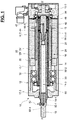
- the actuating cylinder 10 comprises a housing 12, an actuation rod 14 movable axially and coaxially to the axis X-X', a push tube 15 connected to a first end 14-1 of the actuation rod 14, an electric motor 16, and an inverted planetary roller screw mechanism 18 disposed inside the housing 12.
- the screw mechanism 18 is disposed radially between the electric motor 16 and the actuation rod 14.
- the mechanism 18 allows the conversion of rotation movement of the electric motor 16 into a linear movement in translation of the actuation rod 14 along the axis X-X'.
- the electric motor 16 and the screw mechanism 18 are housed entirely within the housing 12.
- the actuation rod 14 extends through the housing 12 and protrudes axially to the outside.
- the housing 12 comprises a tubular main body 12-1, a front cover 12-2 and a rear cover 12-3, said covers being each mounted at one end of the main body 12-1.
- the actuation rod 14 extends through an opening of the front cover 12-2.
- the electric motor 16 comprises a stator 20 fixed on the housing 12, and a rotor 22.
- the stator 20 is fixed in a bore 28 of the main body 12-1 of housing 12.
- the rotor 22 is provided with a tubular rotor shaft 24 and a plurality of permanent magnets 26 supported by said shaft 24.
- the rotor shaft 24 extends axially on either side of the stator 20.
- the electric motor 16 can be of the brushless type, or alternatively of any other suitable type.
- the actuating cylinder 10 also comprises two front rolling bearings 30, 32 and one rear rolling bearing 34.
- the bearings 30, 32, 34 are each of ball type.
- the bearing may be of any other suitable types, for example with tapered rollers or cylindrical rollers.
- the push tube 15 is annular and comprises a portion with an outer thread that is screwed in an inner thread provided to a bore portion of the first end 14-1 of actuation rod 14.
- the push tube 15 may be connected to the actuation rod 14 by any other suitable means, for example by gluing or by fixing screws.
- the inverted planetary roller screw mechanism 18 comprises a screw 40, which is coaxial and connected to a second end 14-2 of the actuation rod 14.
- a portion of screw 40 is provided with an outer thread that is screwed in an inner thread provided to a bore portion of the second end 14-2 of actuation rod 14.
- the screw 40 may be connected to the actuation rod 14 by any other suitable means, for example by gluing or by fixing screws.
- the push tube 15 and the screw 40 are axially opposite one to another with respect to the actuation rod 14.
- the rotor shaft 24 is of tubular shape, is coaxial with the screw 40 and is disposed around said screw 40.
- the screw 40 comprises an external thread 41
- the rotor shaft 24 comprises an internal thread 25 of which the inner diameter is greater than the outer diameter of the external thread 41 of screw 40.
- the screw mechanism 18 further comprises a plurality of rollers 42 having each an external thread (not referenced) which is engaged in the external and internal threads 41, 25 of the screw 40 and the rotor shaft 24, respectively.
- the rollers 42 are identical to one another and are distributed uniformly around the screw 40.
- Each roller 42 extends along an axis parallel to the screw axis.
- each roller 42 comprises, at each end (not referenced), an outer toothing engaged with a synchronization toothing of the screw, and a journal extending axially to the outside from the toothing and housed in a recess in one of the spacer rings 44, 46 mounted around said screw 40.
- the rolling elements are balls engaged in external and internal threads of screw and rotor shaft, respectively.
- the actuation rod 14 is connected to the screw 40 of the screw mechanism 18.
- the rotation of the rotor shaft 24 of the electric motor 16 is converted into a translation of the screw 40 and of the actuation rod 14 along the axis X-X'.
- the actuating cylinder 10 is provided with a lubrication channel 50 that extends through the push tube 15, the actuation rod 14 and the screw 40.
- the lubrication channel 50 comprises a first portion 50-1 consisting in a cylindrical blind hole provided through the push tube 15.
- the first portion 50-1 opens axially towards the actuation rod 14.
- the actuation rod 14 is a tube and comprises a cylindrical bore 14-3 forming a second portion 50-2 of lubrication channel 50.
- the second portion 50-2 opens axially towards the push tube 15 on front axial side, and opens axially towards the screw 40 on rear axial side.
- the second portion 50-2 of lubricant channel 50 comprises at each rod end 14-1 and 14-2 an inner threaded portion that is screwed with the push tube 15 and the screw 40, respectively.
- the lubrication channel 50 comprises a third portion 50-3 consisting in a cylindrical blind hole provided through the screw 40.
- the third portion 50-3 opens axially towards the actuation rod 14.
- the three portions 50-1, 50-2, and 50-3 extend substantially coaxially and are connected one to another by means of the screwed connection between the push tube 15 and the first rod end 14-1 on front axial side, and the screwed connection between the screw 40 and the second rod end 14-2 on rear axial side.
- the lubrication channel 50 further comprises an inlet portion 50-4 that extends radially from the first portion 50-1 provided to the push tube 15.
- the inlet portion 50-4 opens radially to an external surface of the push tube 15.
- the inlet portion 50-4 is provided with a temporary plug or nipple 52 that permits to close the inlet portion 50-4, and then the lubrication channel 50, during the service of the actuating cylinder 10.
- the temporary plug or nipple 52 is removable, in particular during maintenance operations, the inlet portion 50-4 being then connectable to a lubricant pump.
- the lubrication channel 50 also comprises an outlet portion 50-5 that extends radially from the third portion 50-3 provided to the screw 40.
- the outlet portion 50-5 opens radially to the external thread 41 of screw 40.
- the temporary plug or nipple 52 closes the inlet portion 50-4 of channel 50. The channel is then closed to the outside of the actuating cylinder 10.
- the temporary plug or nipple 52 is removed from the inlet portion 50-4.
- a lubricant pump (not represented) is connected to the inlet portion 50-4 and lubricant, for example grease, is supplied to the lubricant channel 50.
- the lubricant flows through the channel 50 successively from the inlet portion 50-4 to the first portion 50-1, the second portion 50-2, the third portion 50-3 and then to the outlet portion 50-5.
- the outlet portion 50-5 is directly open to the external thread 41 of screw, and then to the internal chamber defined between the screw 40 and the rotor shaft 24 and provided with threaded rollers 42 of screw mechanism 18.
- the lubricant is then directly supplied to the contact surfaces between the screw, the rotor shaft, and the rollers, ie. the surfaces that require lubrication to reduced friction and heat exchange.
- the lubricant is supplied directly and only where needed. Only the exact necessary quantity of lubricant is supplied.
- Another advantage of the present invention is that the maintenance operations do not need to be extracted and then reassembled after relubrication.
- the lubrication of the actuating cylinder 10 is simple, efficient and requires a relative short time.
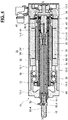
- FIG. 2 A second exemplary embodiment of the present invention is illustrated in Figure 2 , wherein the same elements have the same references, and differs from the previous embodiment in that the bore of actuation rod 14 forming the second portion 50-2 of lubrication channel 50 is of reduced diameter.
- the bore of actuation rod 14 comprises a main cylindrical portion 14-4, and two throttle portions 14-5 and 14-6.
- the main cylindrical portion 14-4 has a diameter smaller than the inner threaded portions of rod ends 14-1, 14-2.
- the first throttle portion 14-5 at first rod end 14-1 permits a diameter transition between the inner threaded portion of large diameter and the main cylindrical portion 14-4 of small diameter.
- the second throttle portion 14-6 at second rod end 14-2 permits a diameter transition between the inner threaded portion of large diameter and the main cylindrical portion 14-4 of small diameter.
- the second portion 50-2 of lubrication channel 50 is formed by the main cylindrical portion 14-4, and the two throttle portions 14-5 and 14-6.
- the second portion 50-2 is in fluidic connection with the first portion 50-1 by the intermediate of the first throttle portion 14-5.
- the second portion 50-2 is in fluidic connection with the third portion 50-1 by the intermediate of the second throttle portion 14-6.
- the second portion 50-2 with the main cylindrical portion 14-4 illustrated in Figure 2 is of smaller diameter than that of the bore 14-3 of the first embodiment illustrated in Figure 1 .
- the portion 14-4 will receive a smaller amount of lubricant. Then a smaller quantity of lubricant is stored there between two refilling maintenance operations, with the risk of denaturing, compared to the first embodiment of the invention.
- FIG. 3 A third exemplary embodiment of the present invention is illustrated in Figure 3 , wherein the same elements have the same references, and differs from the second embodiment in that an actuation rod 60 and the screw of screw mechanism 18 are formed integral.
- the actuation rod 60 illustrated in Figure 3 extends along the axis X-X' and comprises a first rod end 60-1 screwed with the push tube 15 on front axial side.
- the actuation rod comprises a second rod end 60-2 provided with an outer thread 61, the rollers 42 of screw mechanism being engaged with the inner thread 25 of rotor shaft 24 and with the outer thread 61 of second rod end 60-2.
- the actuating cylinder 10 is provided with a lubrication channel 70 that extends through the push tube 15, the actuation rod 60 formed integral with the screw.
- the lubrication channel 70 comprises a first portion 70-1 consisting in a cylindrical blind hole provided through the push tube 15.
- the first portion 70-1 opens axially towards the actuation rod 60.
- the actuation rod 60 comprises a second portion 70-2 consisting in a cylindrical blind hole provided through the actuation rod 60.
- the second portion 70-2 opens axially towards the push tube 15.
- the two portions 70-1 and 70-2 extend substantially coaxially and are connected one to another by means of the screwed connection between the push tube 15 and the first rod end 60-1 on front axial side.
- the lubrication channel 70 further comprises an inlet portion 70-4 that extends radially from the first portion 70-1 provided to the push tube 15.
- the inlet portion 70-4 opens radially to an external surface of the push tube 15.
- the inlet portion 70-4 is provided with a temporary plug or nipple 52 that permits to close the inlet portion 70-4, and then the lubrication channel 70, during the service of the actuating cylinder 10.
- the temporary plug or nipple 52 is removable, in particular during maintenance operations, the inlet portion 70-4 being then connectable to a lubricant pump.
- the lubrication channel 70 also comprises an outlet portion 70-5 that extends radially from the second portion 70-2 provided to the actuation rod 60.
- the outlet portion 70-5 is provided in the second rod end 60-2 provided with the outer thread 61.
- the outlet portion 70-5 opens radially to the external thread 61.
- FIG. 4 A fourth exemplary embodiment of the present invention is illustrated in Figure 4 , wherein the same elements have the same references, and differs from the first embodiment of Figure 1 in that the second portion 50-2 of lubricant channel 50 is formed by a tube 80.
- the actuation rod 14 is a tubular and comprises a cylindrical bore 14-3.
- the lubrication 50 comprises a second portion 50-2 that consists in a cylindrical axial tube 80 arranged in said rod bore 14-3.
- the tube 80 comprises a first end fitted in a cylindrical recess of the push tube 15, the second portion 50-2 being in fluidic connection with the first portion 50-1 of the lubrication channel 50.
- the tube 80 comprises a second end fitted in a cylindrical recess of the screw 40, the second portion 50-2 being in fluidic connection with the third portion 50-3 of the lubrication channel 50.
- the tube 80 is of smaller diameter than that of the bore 14-3, and then permits to receive and store a smaller amount of lubricant. Moreover, the tube 80 can be easily mounted in the screw 40 and the push tube 15. On the contrary a bore with a main cylindrical portion 14-4 of small diameter as illustrated in Figure 2 is quite complex to manufacture due to the important ratio between the axial length and the diameter.
Landscapes
- Engineering & Computer Science (AREA)
- General Engineering & Computer Science (AREA)
- Mechanical Engineering (AREA)
- Power Engineering (AREA)
- Transmission Devices (AREA)
Priority Applications (3)
| Application Number | Priority Date | Filing Date | Title |
|---|---|---|---|
| EP18166510.0A EP3553345A1 (de) | 2018-04-10 | 2018-04-10 | Betätigungszylinder mit schmierstoffnachfüllkanal |
| CN201910276322.1A CN110360284A (zh) | 2018-04-10 | 2019-04-08 | 具有润滑剂填充通道的致动气缸 |
| US16/379,853 US20190309835A1 (en) | 2018-04-10 | 2019-04-10 | Actuating cylinder with lubricant refilling channel |
Applications Claiming Priority (1)
| Application Number | Priority Date | Filing Date | Title |
|---|---|---|---|
| EP18166510.0A EP3553345A1 (de) | 2018-04-10 | 2018-04-10 | Betätigungszylinder mit schmierstoffnachfüllkanal |
Publications (1)
| Publication Number | Publication Date |
|---|---|
| EP3553345A1 true EP3553345A1 (de) | 2019-10-16 |
Family
ID=61965764
Family Applications (1)
| Application Number | Title | Priority Date | Filing Date |
|---|---|---|---|
| EP18166510.0A Withdrawn EP3553345A1 (de) | 2018-04-10 | 2018-04-10 | Betätigungszylinder mit schmierstoffnachfüllkanal |
Country Status (3)
| Country | Link |
|---|---|
| US (1) | US20190309835A1 (de) |
| EP (1) | EP3553345A1 (de) |
| CN (1) | CN110360284A (de) |
Cited By (1)
| Publication number | Priority date | Publication date | Assignee | Title |
|---|---|---|---|---|
| CN114753959A (zh) * | 2022-05-17 | 2022-07-15 | 金陵科技学院 | 一种基于防波堤的自润滑水轮机发电装置 |
Families Citing this family (6)
| Publication number | Priority date | Publication date | Assignee | Title |
|---|---|---|---|---|
| TWI722958B (zh) * | 2019-11-08 | 2021-03-21 | 肯岳亞股份有限公司 | 改良式伺服電動缸結構、其壓床裝置及其更換推進桿及子桿之方法 |
| EP4151884B1 (de) | 2021-09-20 | 2023-11-15 | Diakont S.r.l. | Linearer elektromechanischer aktuator und verfahren zur montage des ausgangselements eines solchen aktuators |
| CN114233840B (zh) * | 2021-12-23 | 2023-03-28 | 苏州英特模科技股份有限公司 | 一种自润滑连接装置 |
| US12000340B1 (en) * | 2023-03-03 | 2024-06-04 | Honeywell International Inc. | Gas turbine engine lubricant flow control system |
| US12209655B1 (en) * | 2023-07-03 | 2025-01-28 | Honeywell International Inc. | Actuator systems for flight control surface |
| US12428135B2 (en) | 2023-07-03 | 2025-09-30 | Honeywell International Inc. | Actuator systems for flight control surface |
Citations (5)
| Publication number | Priority date | Publication date | Assignee | Title |
|---|---|---|---|---|
| DE10235078A1 (de) * | 2002-07-31 | 2004-03-04 | Sew-Eurodrive Gmbh & Co Kg | Spindelmotor |
| US20090260464A1 (en) * | 2008-04-18 | 2009-10-22 | Holker Brett C | Electric actuator |
| DE102009012432A1 (de) * | 2009-03-10 | 2010-09-16 | Robert Bosch Gmbh | Direkte Gewindetriebschmierung |
| WO2015156706A2 (en) * | 2015-05-08 | 2015-10-15 | Zakrytoe Aktsionernoe Obschestvo "Diakont" | Linear electromechanical actuator |
| DE102016218309A1 (de) * | 2015-09-24 | 2017-03-30 | Aktiebolaget Skf | Elektromechanischer Zylinder |
Family Cites Families (1)
| Publication number | Priority date | Publication date | Assignee | Title |
|---|---|---|---|---|
| FR2925640B1 (fr) * | 2007-12-19 | 2010-04-09 | Sagem Defense Securite | Actionneur rotolineaire a rouleaux satellites |
-
2018
- 2018-04-10 EP EP18166510.0A patent/EP3553345A1/de not_active Withdrawn
-
2019
- 2019-04-08 CN CN201910276322.1A patent/CN110360284A/zh active Pending
- 2019-04-10 US US16/379,853 patent/US20190309835A1/en not_active Abandoned
Patent Citations (5)
| Publication number | Priority date | Publication date | Assignee | Title |
|---|---|---|---|---|
| DE10235078A1 (de) * | 2002-07-31 | 2004-03-04 | Sew-Eurodrive Gmbh & Co Kg | Spindelmotor |
| US20090260464A1 (en) * | 2008-04-18 | 2009-10-22 | Holker Brett C | Electric actuator |
| DE102009012432A1 (de) * | 2009-03-10 | 2010-09-16 | Robert Bosch Gmbh | Direkte Gewindetriebschmierung |
| WO2015156706A2 (en) * | 2015-05-08 | 2015-10-15 | Zakrytoe Aktsionernoe Obschestvo "Diakont" | Linear electromechanical actuator |
| DE102016218309A1 (de) * | 2015-09-24 | 2017-03-30 | Aktiebolaget Skf | Elektromechanischer Zylinder |
Cited By (2)
| Publication number | Priority date | Publication date | Assignee | Title |
|---|---|---|---|---|
| CN114753959A (zh) * | 2022-05-17 | 2022-07-15 | 金陵科技学院 | 一种基于防波堤的自润滑水轮机发电装置 |
| CN114753959B (zh) * | 2022-05-17 | 2023-09-12 | 金陵科技学院 | 一种基于防波堤的自润滑水轮机发电装置 |
Also Published As
| Publication number | Publication date |
|---|---|
| US20190309835A1 (en) | 2019-10-10 |
| CN110360284A (zh) | 2019-10-22 |
Similar Documents
| Publication | Publication Date | Title |
|---|---|---|
| US20190309835A1 (en) | Actuating cylinder with lubricant refilling channel | |
| WO2018184026A1 (en) | Improved linear drive actuator | |
| US20150263587A1 (en) | Linear electromechanical actuator | |
| WO2017025118A1 (en) | Roller screw mechanism with cage | |
| CN110578789A (zh) | 一种电动推杆 | |
| CN107407383A (zh) | 线性的执行机构和用于装配执行机构的方法 | |
| EP1917459B1 (de) | Rotations-/linearbewegungsumwandlungsmechanismus | |
| US20210025483A1 (en) | Linear Drive Actuator | |
| CN107429808A (zh) | 线性的执行机构和用于装配该执行机构的方法 | |
| CN220870031U (zh) | 一种电动缸的防转导向结构 | |
| US10473204B2 (en) | Heavy-duty drive axle | |
| EP2255429B1 (de) | Anordnung und verfahren zur montage eines axiallagers in einem hermetischen verdichter | |
| CN208831512U (zh) | 一种耐用的轴套 | |
| CN208457026U (zh) | 一种组合式深沟球轴承 | |
| CN210350941U (zh) | 一种电动推杆 | |
| CN111674462A (zh) | 一种转向器液压结构总成 | |
| CN204628302U (zh) | 圆锥滚子轴承外圈 | |
| CN211174264U (zh) | 一种具有润滑结构的惰齿轮轴及其运动副 | |
| CN214367605U (zh) | 一种用于摩托车变速箱的凸轮轴 | |
| CN205089804U (zh) | 水导轴承 | |
| EP3553921A1 (de) | Betätigungszylinder mit rotorwelle zur lagerung von permanentmagneten | |
| CN111140647A (zh) | 适合免拆卸润滑的线性机电致动器 | |
| CN204628283U (zh) | 双列圆锥滚子轴承 | |
| DE102005011963B4 (de) | Lageranordnung | |
| CN220227530U (zh) | 一种汽车用的防磨损轴套 |
Legal Events
| Date | Code | Title | Description |
|---|---|---|---|
| PUAI | Public reference made under article 153(3) epc to a published international application that has entered the european phase |
Free format text: ORIGINAL CODE: 0009012 |
|
| STAA | Information on the status of an ep patent application or granted ep patent |
Free format text: STATUS: THE APPLICATION HAS BEEN PUBLISHED |
|
| AK | Designated contracting states |
Kind code of ref document: A1 Designated state(s): AL AT BE BG CH CY CZ DE DK EE ES FI FR GB GR HR HU IE IS IT LI LT LU LV MC MK MT NL NO PL PT RO RS SE SI SK SM TR |
|
| AX | Request for extension of the european patent |
Extension state: BA ME |
|
| STAA | Information on the status of an ep patent application or granted ep patent |
Free format text: STATUS: REQUEST FOR EXAMINATION WAS MADE |
|
| 17P | Request for examination filed |
Effective date: 20200320 |
|
| RBV | Designated contracting states (corrected) |
Designated state(s): AL AT BE BG CH CY CZ DE DK EE ES FI FR GB GR HR HU IE IS IT LI LT LU LV MC MK MT NL NO PL PT RO RS SE SI SK SM TR |
|
| RAP1 | Party data changed (applicant data changed or rights of an application transferred) |
Owner name: EWELLIX AB |
|
| STAA | Information on the status of an ep patent application or granted ep patent |
Free format text: STATUS: EXAMINATION IS IN PROGRESS |
|
| 17Q | First examination report despatched |
Effective date: 20210625 |
|
| STAA | Information on the status of an ep patent application or granted ep patent |
Free format text: STATUS: THE APPLICATION IS DEEMED TO BE WITHDRAWN |
|
| 18D | Application deemed to be withdrawn |
Effective date: 20211106 |