EP3553250A1 - Système de formation d'un plancher - Google Patents
Système de formation d'un plancher Download PDFInfo
- Publication number
- EP3553250A1 EP3553250A1 EP18166311.3A EP18166311A EP3553250A1 EP 3553250 A1 EP3553250 A1 EP 3553250A1 EP 18166311 A EP18166311 A EP 18166311A EP 3553250 A1 EP3553250 A1 EP 3553250A1
- Authority
- EP
- European Patent Office
- Prior art keywords
- locking
- angle
- arms
- panels
- groove
- Prior art date
- Legal status (The legal status is an assumption and is not a legal conclusion. Google has not performed a legal analysis and makes no representation as to the accuracy of the status listed.)
- Withdrawn
Links
- 230000015572 biosynthetic process Effects 0.000 title 1
- 239000000203 mixture Substances 0.000 claims description 4
- 239000004033 plastic Substances 0.000 claims description 4
- 229920003023 plastic Polymers 0.000 claims description 4
- 239000002023 wood Substances 0.000 claims description 4
- 238000001125 extrusion Methods 0.000 claims description 3
- 229910052500 inorganic mineral Inorganic materials 0.000 claims description 2
- 239000000463 material Substances 0.000 claims description 2
- 229910052751 metal Inorganic materials 0.000 claims description 2
- 239000002184 metal Substances 0.000 claims description 2
- 239000011707 mineral Substances 0.000 claims description 2
- 238000004519 manufacturing process Methods 0.000 description 4
- 210000003746 feather Anatomy 0.000 description 2
- 238000010438 heat treatment Methods 0.000 description 2
- 238000009434 installation Methods 0.000 description 2
- 230000001154 acute effect Effects 0.000 description 1
- 229910052782 aluminium Inorganic materials 0.000 description 1
- XAGFODPZIPBFFR-UHFFFAOYSA-N aluminium Chemical compound [Al] XAGFODPZIPBFFR-UHFFFAOYSA-N 0.000 description 1
- 239000004020 conductor Substances 0.000 description 1
- 238000005034 decoration Methods 0.000 description 1
- 238000006073 displacement reaction Methods 0.000 description 1
- 230000008030 elimination Effects 0.000 description 1
- 238000003379 elimination reaction Methods 0.000 description 1
- 239000003292 glue Substances 0.000 description 1
- 238000005286 illumination Methods 0.000 description 1
- 239000007788 liquid Substances 0.000 description 1
- 239000004575 stone Substances 0.000 description 1
- 230000000007 visual effect Effects 0.000 description 1
Images

Classifications
-
- E—FIXED CONSTRUCTIONS
- E04—BUILDING
- E04F—FINISHING WORK ON BUILDINGS, e.g. STAIRS, FLOORS
- E04F15/00—Flooring
- E04F15/02—Flooring or floor layers composed of a number of similar elements
- E04F15/02005—Construction of joints, e.g. dividing strips
-
- E—FIXED CONSTRUCTIONS
- E04—BUILDING
- E04F—FINISHING WORK ON BUILDINGS, e.g. STAIRS, FLOORS
- E04F2201/00—Joining sheets or plates or panels
- E04F2201/01—Joining sheets, plates or panels with edges in abutting relationship
- E04F2201/0138—Joining sheets, plates or panels with edges in abutting relationship by moving the sheets, plates or panels perpendicular to the main plane
- E04F2201/0146—Joining sheets, plates or panels with edges in abutting relationship by moving the sheets, plates or panels perpendicular to the main plane with snap action of the edge connectors
-
- E—FIXED CONSTRUCTIONS
- E04—BUILDING
- E04F—FINISHING WORK ON BUILDINGS, e.g. STAIRS, FLOORS
- E04F2201/00—Joining sheets or plates or panels
- E04F2201/05—Separate connectors or inserts, e.g. pegs, pins, keys or strips
- E04F2201/0523—Separate tongues; Interlocking keys, e.g. joining mouldings of circular, square or rectangular shape
- E04F2201/0547—Separate tongues; Interlocking keys, e.g. joining mouldings of circular, square or rectangular shape adapted to be moved perpendicular to the joint edge
Definitions
- the invention relates to a system for forming a floor, consisting of a plurality of panels having a top and a bottom, the profiling on its side edges of a horizontal groove extending in the first groove and a subsequent towards the bottom spring, the top of the spring bottom wall of the groove forms, and having an outgoing from the bottom towards the top extending second groove, wherein each two adjacent panels are connectable and lockable to each other via a separate locking element, and the locking element consists of a base body, at its opposite Each ends an upwardly facing locking hook for cooperation with the second groove and locking two adjacent panels in the horizontal direction, and in its central region two upwardly facing arms with angled at their free ends locking arms for Entw irken with the first grooves and locking the adjacent panels are provided in the vertical direction.
- Such system is for example from the EP 1 119 671 B1 known.
- the locking element is first clipped on a side edge of a panel and then the panel with the clipped-on locking element is placed on the subfloor.
- the panel to be adjacent thereto is lowered in the vertical direction from top to bottom on the subfloor or the locking element.
- the locking arm pivots first and springs, when it comes into coincidence with the horizontal groove back and snaps into the groove.
- the panels are then locked to each other in the horizontal and vertical directions.
- a disadvantage of this locking system is that from the laid floor individual panels or not can be removed only with great difficulty, because the locking arms can be pulled out of the vertical groove only in the horizontal direction.
- the invention has for its object to improve the known floor system so that the disadvantage described is eliminated.
- the upwardly facing surfaces of the locking arms inclined at a first angle to the top extend the upwardly facing surfaces of the locking arms at a first angle to the top inclined
- the downwardly facing surfaces of the springs in run at a second angle to the top
- the first angle is at most as large as the second angle
- the distance between the arms is at least as large as the width of the bottom-facing locking surfaces of the locking arms
- the downwardly facing surfaces of the springs (spring underside) in extend at a second angle to the top inclined
- the first angle is at most as large as the second angle and the distance of the arms to each other at least as large as the width of the downwardly facing locking surfaces of the locking arms.
- the first angle is smaller than the second angle, and more preferably, the panels are identically profiled at all their side edges.
- the spring has a steeper angle to the top of the plate.
- the lower wall of the spring when lowering the panel first touches the outer edge of Verrasthakens, whereby this is pressed towards the center of the already installed locking element and not simply bends, because the whole surface of the spring underside rests on the top of Verrasthakens and after presses down.
- the upwardly facing surfaces of the locking arms are inclined at an angle to the top of the panels, they can dodge in the horizontal groove to the inside, when acting on its upper side, a vertical force. If the distance between the upwardly facing arms is large enough, the arm can swing back so far that the panel to be removed can be easily removed in a vertical direction from the laid floor. Correspondingly simple, a new panel can then be used again by exclusively vertical lowering.
- the panels are designed not only on two opposite, but on all side edges with the same profile, the production is significantly simplified, because the elimination of the profile change facilitates the installation of the manufacturing facility, eliminates multiple tool procurement and storage, and the production control is simplified. Even extremely thin panels with a thickness of less than 4 mm can still be securely connected to each other. Due to the identical profiling, the panels can be laid in all directions, ie also with the long side to the transverse side and vice versa. A herringbone installation is possible. Also, different formats can be mixed together. Both small and large panels, as well as wooden floorboards with stone tiles, etc. In order to allow mixing, the panel formats must be chosen to have a least common denominator both longitudinally and transversely.
- a decorative element can be inserted between the arms to close the gap.
- the decorative element may also protrude above the top of the panels if desired for visual reasons.
- the decorative element can be printed or painted to decorate its surface. Also, another element, such as an aluminum strip can be glued. By co-extrusion of various plastics or differently colored plastics, the surface of the locking element can be decorative.
- the locking element can also be designed such that an LED illumination can be attached between the arms. Between the arms, a channel is formed, which can be heated, for example via a heating medium.
- the heating medium may be liquid or an electrical resistance.
- the locking element is preferably made of plastic, a plastic-wood mixture, a wood material or a plastic-mineral mixture. As a result, the locking element has a certain elasticity, can be compensated with the manufacturing tolerances in the panels. Due to the elasticity of the locking element and larger surfaces of a floor can be laid without expansion joints.
- the latching element may also be made of metal or other conductive material, each being routed continuously (from the roller) through the entire space, and grounded at the end to form a conductive or antistatic floor covering in conjunction with conductive panels or a conductive panel surface ,
- the arms of the locking element facing away from surfaces of the locking hooks extend outwards at an angle to the top of the panels, because the spring then over the angled surface can slide away and then locks between the locking arms and the locking hook.
- the adjacent panel edges are then milled obliquely at the same angle.
- the locking hooks extend at their ends merging into the main body pointed, so that a correspondingly easy to detect and long guideway for the spring is set when connecting horizontally.
- the locking element can also be panel-spreading. This is particularly important when laying with cross joints, which is typically the case with square panels. In conventional systems, the connection ends at a certain distance from the panel edge and the edges tend to Aufstippungen.
- the panel-overlapping locking element connects the two panels in one plane and prevents tipping.
- the locking element can also be designed so that it serves as an expansion joint. It can also protrude beyond the floor surface at the edge, so that it can be inserted over a corresponding receptacle in the profile strip without having to drill holes in the wall of the room.
- the locking element is preferably produced by extrusion.
- the locking element can be preassembled in at least one of the side edges.
- the locking element is preassembled in two mutually angular side edges. For pre-assembly, it is possible to glue the locking element in the side edges.
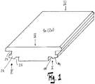
- FIG. 1 shows the perspective view of a panel that can take any shape in itself. It can be square, rectangular, triangular, hexagonal or rhomboid in plan view. In the illustrated form it has four pairs of opposite side edges I, II and III, IV.
- FIG. 2 The profiling of the side edges I, II, III, IV is made FIG. 2 clearly visible.
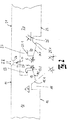
- On the side edges I, II are parallel to the top 11, 21 horizontally extending grooves 13, 23 milled, to which in the direction of bottom 21, 22, a spring 14, 24 connects, the upper side of the lower wall 13.1, 23.1 of the horizontal groove 13, 23 trains.
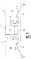
- the spring 14, 24 jumps back relative to the outer edge 17, 27, with which the panels 10, 20 touch, and initially runs essentially straight downwards, is then returned at an angle ⁇ in the direction of the center of the panel and ends with its bottom facing surface 14.1, 24.1 in one from the bottom 12, 22 in the direction of the upper side 11, 21 introduced groove 15, 25.
- the wall of the groove 15.1, 25.1, which adjoins the spring 14, 24 extends at an angle ⁇ to the top 11, 21.
- 20th abut the side edges I, II above the horizontal grooves 14, 24 to each other.
- the chamfers 16, 26 on the side edges I, II are preferred and not necessarily provided.
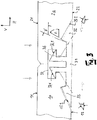
- the locking elements 30 are provided, as in FIGS. 5 and 6 are shown.
- the identical embodiments of both embodiments of the locking elements 30 are provided with identical reference numerals.
- the locking element 30 consists of a base body 31 at its opposite ends locking hooks 32, 33 are provided. In the middle extend from the main body 31, two arms 34, 35, which form locking arms 36, 37 at their upper ends.
- the upper surfaces 36.1, 37.1 of the locking arms 36, 37 extend at an angle ⁇ to horizontal H (top 11, 21 of the panels 10, 20).
- the in the direction of the arms 34, 35 facing surfaces 32.2, 33.2 of the locking hooks 32, 33 extend relative to the horizontal (tops 11, 21 of the panels 10, 20) at an angle ⁇ .
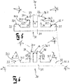
- the upward wall 32.1, 33.1 runs parallel to the top 11, 21, while this wall 32.3, 33.3 at the in FIG. 6 shown embodiment with respect to the horizontal H inclined at an angle ⁇ , so that the locking hooks 32, 33 expire at an acute angle to their ends.
- the panel 10, 20 can also be connected to the locking hook 30 in the horizontal direction H.
- the cooperating with the locking hooks 32, 33 walls 15.2, 25.2 of the grooves 15, 25 are then milled at the same angle, so that they can optionally be supported on the locking hooks 32, 33.
- the angle ⁇ of the groove walls 15.1, 25.1 corresponds to the angle ⁇ of the walls 32.2, 33.2 of the locking hooks 32, 33 pointing in the direction of the arms 34, 35. If the panels 10, 20 are connected to one another, the walls 15.1, 25.1, 32.2, 33.2 abut each other.
- the first angle ⁇ in which the upwardly facing surfaces 36.1, 37.1 of the locking arms 36, 27 are inclined to the upper side 11, 21 is at most as large, but preferably smaller, than the second angle ⁇ with which downwardly facing surfaces 14.1, 24.1 of the springs 14, 24 to the top 11, 21 of the panels 10, 20 are inclined.
- the spring underside 14.1, 24.1 when lowering first the outer edge of the locking arm 36, 37 whereby this is pressed towards the center of the locking member 30 and does not bend, because the entire surface of the spring underside 14.1, 24.1 rests on the surface 36.1, 37.1 of the locking hook 36, 37 and pushes it down.
- the distance a between the arms 34, 35 is arbitrary per se. Of course, the distance a must be so great that the arm 34 or 35, which comes when creating a new panel 10 or 20 with the spring base 14.1 or 24.1 into contact, far enough to the center of the locking element 31 can escape. However, it must correspond at least to the width b of the downwardly facing locking surfaces 36.3, 37.3 of the locking arms 36, 37 (cf. FIGS. 5, 6 ). If it is chosen so large that forms a gap 1 at the side edges I, II of the panels 10, 20, between the arms 34, 35, a decorative element 40 can be used, which is flush with the top 11, 12 or over this can stand out. This decorative element can be dyed or painted for decoration. Instead of a decorative element 40, an LED strip between the arms 34, 35 can be inserted.
Landscapes
- Engineering & Computer Science (AREA)
- Architecture (AREA)
- Civil Engineering (AREA)
- Structural Engineering (AREA)
- Floor Finish (AREA)
Priority Applications (2)
| Application Number | Priority Date | Filing Date | Title |
|---|---|---|---|
| EP18166311.3A EP3553250A1 (fr) | 2018-04-09 | 2018-04-09 | Système de formation d'un plancher |
| PCT/EP2019/058967 WO2019197409A1 (fr) | 2018-04-09 | 2019-04-09 | Système permettant de réaliser un plancher |
Applications Claiming Priority (1)
| Application Number | Priority Date | Filing Date | Title |
|---|---|---|---|
| EP18166311.3A EP3553250A1 (fr) | 2018-04-09 | 2018-04-09 | Système de formation d'un plancher |
Publications (1)
| Publication Number | Publication Date |
|---|---|
| EP3553250A1 true EP3553250A1 (fr) | 2019-10-16 |
Family
ID=61913091
Family Applications (1)
| Application Number | Title | Priority Date | Filing Date |
|---|---|---|---|
| EP18166311.3A Withdrawn EP3553250A1 (fr) | 2018-04-09 | 2018-04-09 | Système de formation d'un plancher |
Country Status (2)
| Country | Link |
|---|---|
| EP (1) | EP3553250A1 (fr) |
| WO (1) | WO2019197409A1 (fr) |
Families Citing this family (1)
| Publication number | Priority date | Publication date | Assignee | Title |
|---|---|---|---|---|
| CN116537487A (zh) * | 2023-05-26 | 2023-08-04 | 浙江晶通新材料集团有限公司 | 一种地板单元及地板连接结构 |
Citations (6)
| Publication number | Priority date | Publication date | Assignee | Title |
|---|---|---|---|---|
| EP1554954A1 (fr) * | 2004-01-13 | 2005-07-20 | Berry Finance Nv | Carreaux de tapis |
| EP1119671B1 (fr) | 1998-10-06 | 2005-09-21 | Pergo (Europe) AB | Système de plancher comportant des lames destinées à être assemblées verticalement et des profilés d'assemblage distincts |
| WO2007136193A1 (fr) * | 2006-05-19 | 2007-11-29 | Hansol Home Deco Co., Ltd. | Plancher démontable à organe de couplage, et son procédé d'assemblage |
| WO2012019411A1 (fr) * | 2010-08-10 | 2012-02-16 | Lv Fengbin | Elément de connexion pour sol chauffant électrique |
| KR20130056702A (ko) * | 2011-11-22 | 2013-05-30 | 삼성에버랜드 주식회사 | 목재 고정장치 및 이를 구비하는 데크 시설물 |
| US20160060880A1 (en) * | 2014-08-27 | 2016-03-03 | Evan J. Stover | Flooring system having assembly clip and related method |
Family Cites Families (1)
| Publication number | Priority date | Publication date | Assignee | Title |
|---|---|---|---|---|
| WO2015170205A1 (fr) * | 2014-05-05 | 2015-11-12 | I Deck S.R.L. | Structure de revêtement de surface adaptée pour être rapidement installée et retirée |
-
2018
- 2018-04-09 EP EP18166311.3A patent/EP3553250A1/fr not_active Withdrawn
-
2019
- 2019-04-09 WO PCT/EP2019/058967 patent/WO2019197409A1/fr not_active Ceased
Patent Citations (6)
| Publication number | Priority date | Publication date | Assignee | Title |
|---|---|---|---|---|
| EP1119671B1 (fr) | 1998-10-06 | 2005-09-21 | Pergo (Europe) AB | Système de plancher comportant des lames destinées à être assemblées verticalement et des profilés d'assemblage distincts |
| EP1554954A1 (fr) * | 2004-01-13 | 2005-07-20 | Berry Finance Nv | Carreaux de tapis |
| WO2007136193A1 (fr) * | 2006-05-19 | 2007-11-29 | Hansol Home Deco Co., Ltd. | Plancher démontable à organe de couplage, et son procédé d'assemblage |
| WO2012019411A1 (fr) * | 2010-08-10 | 2012-02-16 | Lv Fengbin | Elément de connexion pour sol chauffant électrique |
| KR20130056702A (ko) * | 2011-11-22 | 2013-05-30 | 삼성에버랜드 주식회사 | 목재 고정장치 및 이를 구비하는 데크 시설물 |
| US20160060880A1 (en) * | 2014-08-27 | 2016-03-03 | Evan J. Stover | Flooring system having assembly clip and related method |
Also Published As
| Publication number | Publication date |
|---|---|
| WO2019197409A1 (fr) | 2019-10-17 |
Similar Documents
| Publication | Publication Date | Title |
|---|---|---|
| DE102008003550B4 (de) | Einrichtung und Verfahren zum Verriegeln zweier Bodenpaneele | |
| EP1294995B1 (fr) | Système de plancher comprenant un pluralité de planches de plancher identiques | |
| DE102007017087B4 (de) | Paneel, insbesondere Bodenpaneel | |
| EP3298212B1 (fr) | Garniture de panneaux rectangulaires ou carrés joints les uns aux autres | |
| EP2333195B1 (fr) | Sol fabriqué à partir de panneaux de sol dotés de moyens de liaison distincts | |
| DE20220655U1 (de) | Paneel sowie Verriegelungssystem für Paneele | |
| DE102007049792A1 (de) | Verbindung | |
| WO2006032378A1 (fr) | Panneau, notamment panneau de plancher | |
| DE102007002590A1 (de) | Paneel sowie Bodenbelag | |
| EP3307964A1 (fr) | Élément de liaison pour elements structurels de paroi | |
| DE10107866A1 (de) | Abdeckleiste und Halteelement dafür | |
| EP3553250A1 (fr) | Système de formation d'un plancher | |
| EP2112297B1 (fr) | Système d'assemblage pour panneaux de plancher | |
| DE20010913U1 (de) | Platte | |
| DE202016105667U1 (de) | Paneel und mechanische Paneelverbindung | |
| EP3372749B1 (fr) | Système de planches de sol | |
| DE102008003117B4 (de) | Einrichtung zum Verriegeln zweier Bauplatten | |
| WO2013023639A1 (fr) | Revêtement composé de panneaux pouvant être reliés mécaniquement entre eux | |
| DE202008006250U1 (de) | Verbindung | |
| EP2415944B1 (fr) | Panneau de sol doté d'un dispositif de liaison | |
| WO2022058487A1 (fr) | Panneau | |
| DE102006055715A1 (de) | Bodenelement in Form einer verlegbare Bodenplatte und damit gebildeter Verbund | |
| DE202017101029U1 (de) | Paneel und mechanische Paneelverbindung | |
| WO2018069048A1 (fr) | Panneau et système d'assemblage mécanique de panneaux | |
| DE29901547U1 (de) | Abdeckleiste für plattenförmige Bauelemente |
Legal Events
| Date | Code | Title | Description |
|---|---|---|---|
| PUAI | Public reference made under article 153(3) epc to a published international application that has entered the european phase |
Free format text: ORIGINAL CODE: 0009012 |
|
| STAA | Information on the status of an ep patent application or granted ep patent |
Free format text: STATUS: THE APPLICATION HAS BEEN PUBLISHED |
|
| AK | Designated contracting states |
Kind code of ref document: A1 Designated state(s): AL AT BE BG CH CY CZ DE DK EE ES FI FR GB GR HR HU IE IS IT LI LT LU LV MC MK MT NL NO PL PT RO RS SE SI SK SM TR |
|
| AX | Request for extension of the european patent |
Extension state: BA ME |
|
| STAA | Information on the status of an ep patent application or granted ep patent |
Free format text: STATUS: THE APPLICATION IS DEEMED TO BE WITHDRAWN |
|
| 18D | Application deemed to be withdrawn |
Effective date: 20200603 |