EP3553224B1 - Clothes treating apparatus and method for controlling same - Google Patents
Clothes treating apparatus and method for controlling same Download PDFInfo
- Publication number
- EP3553224B1 EP3553224B1 EP17878332.0A EP17878332A EP3553224B1 EP 3553224 B1 EP3553224 B1 EP 3553224B1 EP 17878332 A EP17878332 A EP 17878332A EP 3553224 B1 EP3553224 B1 EP 3553224B1
- Authority
- EP
- European Patent Office
- Prior art keywords
- compressor
- refrigerant
- filter
- fan
- amount
- Prior art date
- Legal status (The legal status is an assumption and is not a legal conclusion. Google has not performed a legal analysis and makes no representation as to the accuracy of the status listed.)
- Active
Links
Images

Classifications
-
- D—TEXTILES; PAPER
- D06—TREATMENT OF TEXTILES OR THE LIKE; LAUNDERING; FLEXIBLE MATERIALS NOT OTHERWISE PROVIDED FOR
- D06F—LAUNDERING, DRYING, IRONING, PRESSING OR FOLDING TEXTILE ARTICLES
- D06F58/00—Domestic laundry dryers
- D06F58/32—Control of operations performed in domestic laundry dryers
- D06F58/34—Control of operations performed in domestic laundry dryers characterised by the purpose or target of the control
- D06F58/36—Control of operational steps, e.g. for optimisation or improvement of operational steps depending on the condition of the laundry
- D06F58/38—Control of operational steps, e.g. for optimisation or improvement of operational steps depending on the condition of the laundry of drying, e.g. to achieve the target humidity
-
- F—MECHANICAL ENGINEERING; LIGHTING; HEATING; WEAPONS; BLASTING
- F25—REFRIGERATION OR COOLING; COMBINED HEATING AND REFRIGERATION SYSTEMS; HEAT PUMP SYSTEMS; MANUFACTURE OR STORAGE OF ICE; LIQUEFACTION SOLIDIFICATION OF GASES
- F25B—REFRIGERATION MACHINES, PLANTS OR SYSTEMS; COMBINED HEATING AND REFRIGERATION SYSTEMS; HEAT PUMP SYSTEMS
- F25B31/00—Compressor arrangements
- F25B31/002—Lubrication
-
- F—MECHANICAL ENGINEERING; LIGHTING; HEATING; WEAPONS; BLASTING
- F25—REFRIGERATION OR COOLING; COMBINED HEATING AND REFRIGERATION SYSTEMS; HEAT PUMP SYSTEMS; MANUFACTURE OR STORAGE OF ICE; LIQUEFACTION SOLIDIFICATION OF GASES
- F25B—REFRIGERATION MACHINES, PLANTS OR SYSTEMS; COMBINED HEATING AND REFRIGERATION SYSTEMS; HEAT PUMP SYSTEMS
- F25B49/00—Arrangement or mounting of control or safety devices
- F25B49/02—Arrangement or mounting of control or safety devices for compression type machines, plants or systems
-
- D—TEXTILES; PAPER
- D06—TREATMENT OF TEXTILES OR THE LIKE; LAUNDERING; FLEXIBLE MATERIALS NOT OTHERWISE PROVIDED FOR
- D06F—LAUNDERING, DRYING, IRONING, PRESSING OR FOLDING TEXTILE ARTICLES
- D06F2103/00—Parameters monitored or detected for the control of domestic laundry washing machines, washer-dryers or laundry dryers
- D06F2103/02—Characteristics of laundry or load
- D06F2103/08—Humidity
-
- D—TEXTILES; PAPER
- D06—TREATMENT OF TEXTILES OR THE LIKE; LAUNDERING; FLEXIBLE MATERIALS NOT OTHERWISE PROVIDED FOR
- D06F—LAUNDERING, DRYING, IRONING, PRESSING OR FOLDING TEXTILE ARTICLES
- D06F2103/00—Parameters monitored or detected for the control of domestic laundry washing machines, washer-dryers or laundry dryers
- D06F2103/28—Air properties
- D06F2103/30—Pressure
-
- D—TEXTILES; PAPER
- D06—TREATMENT OF TEXTILES OR THE LIKE; LAUNDERING; FLEXIBLE MATERIALS NOT OTHERWISE PROVIDED FOR
- D06F—LAUNDERING, DRYING, IRONING, PRESSING OR FOLDING TEXTILE ARTICLES
- D06F2103/00—Parameters monitored or detected for the control of domestic laundry washing machines, washer-dryers or laundry dryers
- D06F2103/38—Time, e.g. duration
-
- D—TEXTILES; PAPER
- D06—TREATMENT OF TEXTILES OR THE LIKE; LAUNDERING; FLEXIBLE MATERIALS NOT OTHERWISE PROVIDED FOR
- D06F—LAUNDERING, DRYING, IRONING, PRESSING OR FOLDING TEXTILE ARTICLES
- D06F2103/00—Parameters monitored or detected for the control of domestic laundry washing machines, washer-dryers or laundry dryers
- D06F2103/42—Parameters monitored or detected for the control of domestic laundry washing machines, washer-dryers or laundry dryers related to filters or pumps
-
- D—TEXTILES; PAPER
- D06—TREATMENT OF TEXTILES OR THE LIKE; LAUNDERING; FLEXIBLE MATERIALS NOT OTHERWISE PROVIDED FOR
- D06F—LAUNDERING, DRYING, IRONING, PRESSING OR FOLDING TEXTILE ARTICLES
- D06F2103/00—Parameters monitored or detected for the control of domestic laundry washing machines, washer-dryers or laundry dryers
- D06F2103/44—Current or voltage
-
- D—TEXTILES; PAPER
- D06—TREATMENT OF TEXTILES OR THE LIKE; LAUNDERING; FLEXIBLE MATERIALS NOT OTHERWISE PROVIDED FOR
- D06F—LAUNDERING, DRYING, IRONING, PRESSING OR FOLDING TEXTILE ARTICLES
- D06F2103/00—Parameters monitored or detected for the control of domestic laundry washing machines, washer-dryers or laundry dryers
- D06F2103/50—Parameters monitored or detected for the control of domestic laundry washing machines, washer-dryers or laundry dryers related to heat pumps, e.g. pressure or flow rate
-
- D—TEXTILES; PAPER
- D06—TREATMENT OF TEXTILES OR THE LIKE; LAUNDERING; FLEXIBLE MATERIALS NOT OTHERWISE PROVIDED FOR
- D06F—LAUNDERING, DRYING, IRONING, PRESSING OR FOLDING TEXTILE ARTICLES
- D06F2103/00—Parameters monitored or detected for the control of domestic laundry washing machines, washer-dryers or laundry dryers
- D06F2103/54—Parameters monitored or detected for the control of domestic laundry washing machines, washer-dryers or laundry dryers related to blowers or fans
-
- D—TEXTILES; PAPER
- D06—TREATMENT OF TEXTILES OR THE LIKE; LAUNDERING; FLEXIBLE MATERIALS NOT OTHERWISE PROVIDED FOR
- D06F—LAUNDERING, DRYING, IRONING, PRESSING OR FOLDING TEXTILE ARTICLES
- D06F2105/00—Systems or parameters controlled or affected by the control systems of washing machines, washer-dryers or laundry dryers
- D06F2105/26—Heat pumps
-
- D—TEXTILES; PAPER
- D06—TREATMENT OF TEXTILES OR THE LIKE; LAUNDERING; FLEXIBLE MATERIALS NOT OTHERWISE PROVIDED FOR
- D06F—LAUNDERING, DRYING, IRONING, PRESSING OR FOLDING TEXTILE ARTICLES
- D06F2105/00—Systems or parameters controlled or affected by the control systems of washing machines, washer-dryers or laundry dryers
- D06F2105/30—Blowers
-
- D—TEXTILES; PAPER
- D06—TREATMENT OF TEXTILES OR THE LIKE; LAUNDERING; FLEXIBLE MATERIALS NOT OTHERWISE PROVIDED FOR
- D06F—LAUNDERING, DRYING, IRONING, PRESSING OR FOLDING TEXTILE ARTICLES
- D06F2105/00—Systems or parameters controlled or affected by the control systems of washing machines, washer-dryers or laundry dryers
- D06F2105/34—Filtering, e.g. control of lint removal devices
-
- D—TEXTILES; PAPER
- D06—TREATMENT OF TEXTILES OR THE LIKE; LAUNDERING; FLEXIBLE MATERIALS NOT OTHERWISE PROVIDED FOR
- D06F—LAUNDERING, DRYING, IRONING, PRESSING OR FOLDING TEXTILE ARTICLES
- D06F2105/00—Systems or parameters controlled or affected by the control systems of washing machines, washer-dryers or laundry dryers
- D06F2105/52—Changing sequence of operational steps; Carrying out additional operational steps; Modifying operational steps, e.g. by extending duration of steps
-
- D—TEXTILES; PAPER
- D06—TREATMENT OF TEXTILES OR THE LIKE; LAUNDERING; FLEXIBLE MATERIALS NOT OTHERWISE PROVIDED FOR
- D06F—LAUNDERING, DRYING, IRONING, PRESSING OR FOLDING TEXTILE ARTICLES
- D06F2105/00—Systems or parameters controlled or affected by the control systems of washing machines, washer-dryers or laundry dryers
- D06F2105/62—Stopping or disabling machine operation
-
- D—TEXTILES; PAPER
- D06—TREATMENT OF TEXTILES OR THE LIKE; LAUNDERING; FLEXIBLE MATERIALS NOT OTHERWISE PROVIDED FOR
- D06F—LAUNDERING, DRYING, IRONING, PRESSING OR FOLDING TEXTILE ARTICLES
- D06F25/00—Washing machines with receptacles, e.g. perforated, having a rotary movement, e.g. oscillatory movement, the receptacle serving both for washing and for centrifugally separating water from the laundry and having further drying means, e.g. using hot air
-
- D—TEXTILES; PAPER
- D06—TREATMENT OF TEXTILES OR THE LIKE; LAUNDERING; FLEXIBLE MATERIALS NOT OTHERWISE PROVIDED FOR
- D06F—LAUNDERING, DRYING, IRONING, PRESSING OR FOLDING TEXTILE ARTICLES
- D06F58/00—Domestic laundry dryers
- D06F58/02—Domestic laundry dryers having dryer drums rotating about a horizontal axis
- D06F58/04—Details
-
- D—TEXTILES; PAPER
- D06—TREATMENT OF TEXTILES OR THE LIKE; LAUNDERING; FLEXIBLE MATERIALS NOT OTHERWISE PROVIDED FOR
- D06F—LAUNDERING, DRYING, IRONING, PRESSING OR FOLDING TEXTILE ARTICLES
- D06F58/00—Domestic laundry dryers
- D06F58/20—General details of domestic laundry dryers
-
- D—TEXTILES; PAPER
- D06—TREATMENT OF TEXTILES OR THE LIKE; LAUNDERING; FLEXIBLE MATERIALS NOT OTHERWISE PROVIDED FOR
- D06F—LAUNDERING, DRYING, IRONING, PRESSING OR FOLDING TEXTILE ARTICLES
- D06F58/00—Domestic laundry dryers
- D06F58/20—General details of domestic laundry dryers
- D06F58/206—Heat pump arrangements
-
- D—TEXTILES; PAPER
- D06—TREATMENT OF TEXTILES OR THE LIKE; LAUNDERING; FLEXIBLE MATERIALS NOT OTHERWISE PROVIDED FOR
- D06F—LAUNDERING, DRYING, IRONING, PRESSING OR FOLDING TEXTILE ARTICLES
- D06F58/00—Domestic laundry dryers
- D06F58/20—General details of domestic laundry dryers
- D06F58/22—Lint collecting arrangements
-
- D—TEXTILES; PAPER
- D06—TREATMENT OF TEXTILES OR THE LIKE; LAUNDERING; FLEXIBLE MATERIALS NOT OTHERWISE PROVIDED FOR
- D06F—LAUNDERING, DRYING, IRONING, PRESSING OR FOLDING TEXTILE ARTICLES
- D06F58/00—Domestic laundry dryers
- D06F58/20—General details of domestic laundry dryers
- D06F58/24—Condensing arrangements
-
- D—TEXTILES; PAPER
- D06—TREATMENT OF TEXTILES OR THE LIKE; LAUNDERING; FLEXIBLE MATERIALS NOT OTHERWISE PROVIDED FOR
- D06F—LAUNDERING, DRYING, IRONING, PRESSING OR FOLDING TEXTILE ARTICLES
- D06F58/00—Domestic laundry dryers
- D06F58/32—Control of operations performed in domestic laundry dryers
- D06F58/34—Control of operations performed in domestic laundry dryers characterised by the purpose or target of the control
- D06F58/50—Responding to irregular working conditions, e.g. malfunctioning of blowers
-
- F—MECHANICAL ENGINEERING; LIGHTING; HEATING; WEAPONS; BLASTING
- F04—POSITIVE - DISPLACEMENT MACHINES FOR LIQUIDS; PUMPS FOR LIQUIDS OR ELASTIC FLUIDS
- F04B—POSITIVE-DISPLACEMENT MACHINES FOR LIQUIDS; PUMPS
- F04B35/00—Piston pumps specially adapted for elastic fluids and characterised by the driving means to their working members, or by combination with, or adaptation to, specific driving engines or motors, not otherwise provided for
- F04B35/04—Piston pumps specially adapted for elastic fluids and characterised by the driving means to their working members, or by combination with, or adaptation to, specific driving engines or motors, not otherwise provided for the means being electric
-
- F—MECHANICAL ENGINEERING; LIGHTING; HEATING; WEAPONS; BLASTING
- F25—REFRIGERATION OR COOLING; COMBINED HEATING AND REFRIGERATION SYSTEMS; HEAT PUMP SYSTEMS; MANUFACTURE OR STORAGE OF ICE; LIQUEFACTION SOLIDIFICATION OF GASES
- F25B—REFRIGERATION MACHINES, PLANTS OR SYSTEMS; COMBINED HEATING AND REFRIGERATION SYSTEMS; HEAT PUMP SYSTEMS
- F25B1/00—Compression machines, plants or systems with non-reversible cycle
- F25B1/02—Compression machines, plants or systems with non-reversible cycle with compressor of reciprocating-piston type
-
- F—MECHANICAL ENGINEERING; LIGHTING; HEATING; WEAPONS; BLASTING
- F25—REFRIGERATION OR COOLING; COMBINED HEATING AND REFRIGERATION SYSTEMS; HEAT PUMP SYSTEMS; MANUFACTURE OR STORAGE OF ICE; LIQUEFACTION SOLIDIFICATION OF GASES
- F25B—REFRIGERATION MACHINES, PLANTS OR SYSTEMS; COMBINED HEATING AND REFRIGERATION SYSTEMS; HEAT PUMP SYSTEMS
- F25B1/00—Compression machines, plants or systems with non-reversible cycle
- F25B1/04—Compression machines, plants or systems with non-reversible cycle with compressor of rotary type
-
- F—MECHANICAL ENGINEERING; LIGHTING; HEATING; WEAPONS; BLASTING
- F25—REFRIGERATION OR COOLING; COMBINED HEATING AND REFRIGERATION SYSTEMS; HEAT PUMP SYSTEMS; MANUFACTURE OR STORAGE OF ICE; LIQUEFACTION SOLIDIFICATION OF GASES
- F25B—REFRIGERATION MACHINES, PLANTS OR SYSTEMS; COMBINED HEATING AND REFRIGERATION SYSTEMS; HEAT PUMP SYSTEMS
- F25B2600/00—Control issues
- F25B2600/02—Compressor control
- F25B2600/024—Compressor control by controlling the electric parameters, e.g. current or voltage
-
- F—MECHANICAL ENGINEERING; LIGHTING; HEATING; WEAPONS; BLASTING
- F25—REFRIGERATION OR COOLING; COMBINED HEATING AND REFRIGERATION SYSTEMS; HEAT PUMP SYSTEMS; MANUFACTURE OR STORAGE OF ICE; LIQUEFACTION SOLIDIFICATION OF GASES
- F25B—REFRIGERATION MACHINES, PLANTS OR SYSTEMS; COMBINED HEATING AND REFRIGERATION SYSTEMS; HEAT PUMP SYSTEMS
- F25B2600/00—Control issues
- F25B2600/02—Compressor control
- F25B2600/025—Compressor control by controlling speed
- F25B2600/0251—Compressor control by controlling speed with on-off operation
-
- F—MECHANICAL ENGINEERING; LIGHTING; HEATING; WEAPONS; BLASTING
- F25—REFRIGERATION OR COOLING; COMBINED HEATING AND REFRIGERATION SYSTEMS; HEAT PUMP SYSTEMS; MANUFACTURE OR STORAGE OF ICE; LIQUEFACTION SOLIDIFICATION OF GASES
- F25B—REFRIGERATION MACHINES, PLANTS OR SYSTEMS; COMBINED HEATING AND REFRIGERATION SYSTEMS; HEAT PUMP SYSTEMS
- F25B2600/00—Control issues
- F25B2600/25—Control of valves
- F25B2600/2513—Expansion valves
-
- F—MECHANICAL ENGINEERING; LIGHTING; HEATING; WEAPONS; BLASTING
- F25—REFRIGERATION OR COOLING; COMBINED HEATING AND REFRIGERATION SYSTEMS; HEAT PUMP SYSTEMS; MANUFACTURE OR STORAGE OF ICE; LIQUEFACTION SOLIDIFICATION OF GASES
- F25B—REFRIGERATION MACHINES, PLANTS OR SYSTEMS; COMBINED HEATING AND REFRIGERATION SYSTEMS; HEAT PUMP SYSTEMS
- F25B2700/00—Sensing or detecting of parameters; Sensors therefor
- F25B2700/21—Temperatures
- F25B2700/2115—Temperatures of a compressor or the drive means therefor
- F25B2700/21152—Temperatures of a compressor or the drive means therefor at the discharge side of the compressor
Definitions
- the present invention relates to a clothes treating apparatus with a heat pump, and a method of controlling the clothes treating apparatus.
- a clothes treating apparatus for drying clothes is typically provided with a container for storing clothes and a hot air supply unit for supplying heated air.
- Some conventional clothes treating apparatus uses a heat pump as a hot air supply unit.
- the heat pump is a means for dehumidifying air discharged from a container and heating the dehumidified air by circulating refrigerant along an evaporator, a compressor, a condenser, and an expansion valve.
- Such an apparatus is, for example, known from JP 2007 061264 A .
- the compressor in the heat pump is a means for compressing the refrigerant discharged from the evaporator and supplying the compressed refrigerant to the condenser, and the refrigerant is circulated along a refrigerant pipe by the compressor.
- the compressor is either a reciprocating compressor or a rotary compressor. In both cases, only when lubricant is supplied to a compression chamber in the compressor, the durability of the compressor may be maintained. Accordingly, the heat pump having the compressor in which the lubricant is supplied to the compression chamber for compressing the refrigerant suffers from discharge of the lubricant together with the refrigerant into the refrigerant pipe.
- the discharge of the refrigerant from the compressor into the refrigerant pipe leads to a decrease in the amount of the lubricant stored in the compressor, thereby decreasing the durability of the compressor and the efficiency of heat exchange between the refrigerant and air in the evaporator or the condenser.
- An aspect of the present invention devised to solve the conventional problem is to provide a clothes treating apparatus which minimizes the amount of residual lubricant in a refrigerant pipe, and a method of controlling the clothes treating apparatus.
- the clothes treating apparatus includes, amongst others, a container configured to accommodate clothes therein, a duct forming a passage configured to circulate air inside the container therethrough, a fan provided in the duct, a refrigerant pipe forming a refrigerant circulation passage, an evaporator configured to evaporate refrigerant by exchanging heat with air, a condenser configured to condense the refrigerant by exchanging heat with air passed through the evaporator, a compressor configured to compress the refrigerant discharged from the evaporator and transferring the compressed refrigerant to the condenser, and an expansion valve configured to open and close the refrigerant pipe.
- the method includes, amongst others, a circulation step of circulating air by operating the fan, a heat exchange step of opening the refrigerant pipe by controlling the expansion valve, and circulating the refrigerant by operating the compressor, a circulation termination step of terminating the operation of the fan, if a dryness level of clothes stored in the container has reached a predetermined reference dryness level or a progress time of the heat exchange step has reached a predetermined reference time, and a retrieval step of closing the refrigerant pipe by controlling the expansion valve, and retrieving the refrigerant and lubricant from the refrigerant pipe to the compressor by operating the compressor.
- the compressor may include a compression unit configured to make rotating motion inside the compressor.
- a number of revolutions of the compression unit is set to be less in the retrieval step than in the heat exchange step.
- the compressor may include a compression unit configured to make a linear reciprocating motion inside the compressor.
- a reciprocating cycle of the compression unit is then be set to be longer in the retrieval step than in the heat exchange step.
- the method of controlling a clothes treating apparatus may further include a cooling step of dropping a temperature of the clothes stored in the container by operating the fan, the cooling step being initiated after completion of the retrieval step.
- the method of controlling a clothes treating apparatus may further include a residual amount determination step of determining whether the amount of a foreign material remaining in a filter filtering air introduced into the duct is equal to or larger than a predetermined reference amount, performed during the circulation step in progress, a fan operation termination step of, if the amount of the foreign material remaining in the filter is equal to or larger than the predetermined reference amount, terminating operation of the filter, and a filter cleaning step of operating a filter cleaning unit configured to spray water onto the filter, after the operation of the fan is terminated.
- the method of controlling a clothes treating apparatus may further include an interim retrieval step of, when the rotation of the fan is terminated in the fan operation termination step, closing the refrigerant pipe by controlling the expansion valve, and retrieving the refrigerant and lubricant from the refrigerant pipe to the compressor by operating the compressor.
- a progress time of the interim retrieval step may be set to be equal to or shorter than a progress time of the filter cleaning step.
- the method of controlling a clothes treating apparatus may further include a water film removal step of rotating the fan at a larger number of revolutions than a number of revolutions of the fan set in the circulation step, after completing the filter cleaning step.
- the circulation step and the heat exchange step may be resumed after the completion of the water film removal step.
- the fan may include an impeller provided inside the duct and a motor configured to rotate the impeller, a number of revolutions of the impeller may be maintained to be a predetermined reference number of revolutions in the circulation step, and if the amount of current supplied to the motor to maintain the number of revolutions of the impeller to be the reference number of revolutions in the circulation step is equal to or less than a reference current amount, it may be determined that the amount of the foreign material remaining in the filer is equal to or larger than the reference amount in the residual amount determination step.
- the container may include a tub configured to store water therein and a drum rotatably provided inside the tub and configured to store clothes therein, and if a pressure output from a pressure sensing unit configured to sense the internal pressure of the tub is equal to higher than a predetermined reference pressure, it may be determined that the amount of the foreign material remaining in the filer is equal to or larger than the reference amount in the residual amount determination step.
- a temperature of the refrigerant discharged from the compressor is equal to or higher than a predetermined reference temperature, it may be determined that the amount of the foreign material remaining in the filer is equal to or larger than the reference amount in the residual amount determination step.
- a clothes treating apparatus in another aspect of the present invention, includes, amongst others, a container configured to accommodate clothes therein, a duct forming a passage for circulating air inside the container therethrough, a fan provided in the duct, a heat pump including a refrigerant pipe forming a refrigerant circulation passage, an evaporator configured to evaporate refrigerant by exchanging heat with air introduced into the duct, a condenser configured to condense the refrigerant by exchanging heat with air passed through the evaporator, a compressor configured to compress the refrigerant discharged from the evaporator and transferring the compressed refrigerant to the condenser, and an expansion valve configured to open and close the refrigerant pipe, and a controller configured to control the fan and the heat pump.
- the controller determines that operation of the fan is completed, the controller is configured to close the refrigerant pipe by controlling the expansion value, and operate the compressor to retrieve the refrigerant and lubricant from the refrigerant pipe to the compressor.
- the clothes treating apparatus further includes a sensor provided inside the container or the duct, to measure a dryness level of the clothes stored in the container.
- the controller determines that the dryness level of the clothes stored in the container has reached a predetermined reference dryness level, the controller is configured to terminate the operation of the fan.
- the clothes treating apparatus according to the present invention may further include a filter configured to filter air introduced into the duct.
- the controller may be configured to terminate the operation of the fan.
- the clothes treating apparatus may further include a filter cleaning unit configured to clean the foreign material remaining in the filter.
- the controller may be configured to control the filter cleaning unit to clean the filter.
- the present invention has the effect of providing a clothes treating apparatus which minimizes the amount of residual lubricant in a refrigerant pipe, and a method of controlling the clothes treating apparatus.
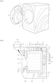
- a clothes treating apparatus 100 includes a cabinet 1, a container 2 disposed inside the cabinet 1 and providing a space for accommodating clothes therein, and a hot air supply unit 7, 8 and 9 supplying heated air (hot air) into the container 2.
- the cabinet 1 is provided, on a front surface thereof, with an opening 11 through which clothes are put in or taken out from the container 2, and the opening 11 is opened and closed by a door 13 rotatably fixed to the cabinet 1.
- the door 13 may include a control panel 15 which receives a control command from a user and displays the progress of executing the received control command.
- the control panel 15 may include an input unit 151 which receives a control command from the user and a display 153 which displays control commands available to the user or information about the progress of executing a user-selected control command.
- the container 2 may include a tub 21 which is disposed inside the cabinet 1 and provides a space for storing water therein, and a drum 24 which is rotatably provided inside the tub 21 and provides a space for storing clothes therein.
- the tub 21 is fixed inside the cabinet 1 through a support unit 215.
- the support unit 215 may include a spring and a damper which prevent transfer of vibrations generated in the tub 21 to the cabinet 1.
- the tub 21 includes a tub opening 211 communicating with the opening 11, and the opening 11 is coupled to the tub opening 211 through a gasket 213.
- the gasket 213 is a means for preventing leakage of water stored in the tub 21 into the cabinet 1.
- the tub 21 may receive water through a water supply pipe 31 and discharge water inside the tub 21 to the outside the cabinet 1 through a drain pipe 41.
- the water supply pipe 31 is configured to couple a water supply (not shown) residing outside the cabinet to the tub 21, and is opened or closed by means of a first valve 33 under the control of a controller (not shown).
- the drain pipe 41 is a passage along which the water in the tub 21 is guided to the outside of the cabinet 1.
- the drain pipe 41 is provided with a pump 43.
- a water level in the tub 21 may be controlled through a pressure sensing unit 27.
- the pressure sensing unit 27 may include a communication pipe 271 communicating with the inside of the tub 21 and a pressure sensor 273 sensing an internal pressure of the communication pipe 271.
- FIG. 2 illustrates an example in which the communication pipe 271 communicates with the inside of the tub 21 through the drain pipe 41.
- the controller may determine the water level in the tub 21 based on data (voltage or current) output from the pressure sensor 273.
- the drum 24 includes a drum opening 241 communicating with the opening 11 and the tub opening 211, and a plurality of through holes 243 communicating the inside of the drum 24 with the inside of the tub 21.
- the drum 24 is rotated by a drum drive unit 25 inside the cabinet 1.
- the drum drive unit 25 may include a stator 251 which is fixed to the rear surface of the tub 21, to generate a rotating field, upon receipt of current, a rotor 255 which is rotated by the rotating field, and a rotation shaft 253 which couples the drum 24 to the rotor 255.
- the hot air supply unit 7, 8 and 9 may include a duct 7 positioned outside the tub 21 and forming an air circulation passage, a fan 8 disposed inside the duct 7 and blowing air in the tub 21, and a heat pump 9 dehumidifying and heating air introduced into the duct 7.
- the duct 7 has one end coupled to an outlet penetrating through the tub 21 and the other end coupled to an inlet 219 penetrating through the tub 21, and a filter 217 may be provided in the outlet, to filter the air introduced into the duct 7.
- the clothes treating apparatus 100 may further include a filter cleaning unit 35 and 37 for cleaning the filter 217.
- the filter cleaning unit 35 and 37 may include a sprayer 39 fixed inside the duct 7, a second water supply pipe 35 which couples the sprayer 39 to the water supply (not shown), and a second valve 37 which opens and closes the second water supply pipe 35 under the control of the controller.
- the fan 8 may include an impeller 81 which is rotatably disposed inside the duct 7 and a fan motor 83 which is fixed to the exterior of the duct 7 and rotates the impeller 81.
- the heat pump 9 may include a refrigerant pipe 99 which forms a refrigerant circulation passage, an evaporator 91 which is positioned inside the duct 7 and fixed to the refrigerant pipe 99, a condenser 93 which is positioned inside the duct 7 and fixed to the refrigerant pipe 99, a compressor 95 which compresses refrigerant passed through the evaporator 91 and transfers the compressed refrigerant to the condenser 93, and an expansion valve 97 which opens or closes the refrigerant pipe 99 (controls the flow rate of the refrigerant) and thus controls the pressure of the refrigerant discharged from the condenser 93.
- a refrigerant pipe 99 which forms a refrigerant circulation passage
- an evaporator 91 which is positioned inside the duct 7 and fixed to the refrigerant pipe 99
- a condenser 93 which is positioned inside the duct 7 and fixed to the refrigerant pipe 99
- a compressor 95
- the refrigerant passed through the evaporator 91 may evaporate inside the refrigerant pipe 99, and since the condenser 93 emits heat to the air passed through the evaporator 91, the refrigerant passed through the condenser 93 may be condensed inside the refrigerant pipe 99. Therefore, the air passed through the evaporator 91 is cooled, whereas the air passed through the condenser 93 is heated.
- the compressor 95 may be of any type, for example, a reciprocating compressor, a rotary compressor, or a scroll compressor.
- FIG. 3 illustrates an exemplary rotary compressor.
- a compressor 95 illustrated in FIG. 3 may include a case 951, a shaft 955 rotatably disposed inside the case 951, a drive unit 956 and 957 rotating the shaft 955, and a compression chamber 958 disposed inside the case 951 and compressing refrigerant.
- the case 951 includes an inlet 951a which guides the refrigerant discharged from the evaporator 91 to the compression chamber 958, and an outlet 951b which discharges the compressed refrigerant to the outside of the case 951.
- the shaft 955 is rotatably supported inside the case 951 by a first bearing housing 952 and a second bearing housing 953 which are fixed inside the case 951.
- the drive unit 956 and 957 may include a stator 956 which is fixed to the case 951 and forms a rotating field and a rotor 957 which is fixed to the shaft 955 and rotates by the rotating field.
- the shaft 955 is provided with a compression unit 9553 rotating eccentrically in the compression chamber 958.
- the compression chamber 958 includes a chamber 958a fixed to the case 951 and providing a space for accommodating the compression unit 9553 therein, a partition 958b separating the inner space of the chamber 958a, a spring 958c providing elastic force to the partition 958b, and a chamber outlet 958d discharging the refrigerant from the chamber 958a.
- the compression unit 9553 rotates along with the shaft 955, and the refrigerant compressed in the chamber 958a by the compression unit 9553 is supplied to the condenser 93 through the chamber outlet 958d and the outlet 951c.
- a supply for supplying lubricant to the chamber 958a is provided in the case 951.
- the supply is provided as a passage 9551 which is defined inside the shaft 955 and guides lubricant stored in the case 951 to the chamber 958a.
- FIG. 4 illustrates an exemplary reciprocating compressor.
- a compressor 95 may include the case 951, the chamber 958a which is disposed in the case 951, receives refrigerant through the inlet 951a, and discharges the refrigerant through the outlet 951b, the compression unit 9553 which makes a linear reciprocating motion in the chamber 958a, a rotating plate 959a which is rotated by a motor, and a link 959b which couples the rotating plate 959a to the compression unit 9553 and converts a rotational motion to a linear motion.
- the compressor 95 according to this embodiment also includes the supply 9551 supplying lubricant to the chamber 958a.
- the supply 9551 is a passage coupled to the chamber 958a, penetrating through the case 951.
- the supply 9551 supplying lubricant to the chamber 958a is essential to the compressor 95. If the lubricant is supplied to the chamber 958a, the resulting reduced friction between the compression unit 9553 and the chamber 958a may increase the durability of the compressor 95. Despite this benefit, the lubricant may be circulated along with the refrigerant compressed in the chamber 958a along the refrigerant pipe 99.
- the lubricant is discharged to the outside of the compressor 95 and circulated along the refrigerant pipe 99, the amount of the lubricant stored in the case 951 is reduced, thereby decreasing the efficiency of heat exchange between the refrigerant and air in the evaporator 91 or the condenser 93 as well as the durability of the compression unit 9553 and the chamber 958a. This problem may be more frequent, when the compressor 95 is disposed in parallel to the bottom surface of the cabinet.
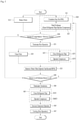
- a control method according to an embodiment of the present invention may minimize the amount of residual lubricant in the refrigerant pipe 99 by a control operation illustrated in FIG. 5 .
- a description will be given of the control method according to an embodiment of the present invention in the context of the compressor illustrated in FIG. 3 .
- the control method may include a drying step S10 and S20 of supplying hot air into the container 2, a retrieval step S43 of retrieving lubricant from the refrigerant pipe 99, which is initiated when the dryness level of clothes has reached a predetermined reference dryness level or a dry time (reference time) set before a hot air supply step starts (S40) has elapsed, and a cooling step S47 initiated after the retrieval step S43.
- the drying step may include a drum rotation step S10 of rotating the drum 24 by supplying power to the stator 251 of the drum drive unit, and a hot air supply step S20 of dehumidifying and heating air introduced into the duct 7 by operating the fan 8 and the heat pump 9.
- the hot air supply step S20 may include a circulation step S21 of rotating the impeller 81 by supplying power to the fan motor 83, and a heat exchange step S23 of circulating refrigerant along the refrigerant pipe 99 by controlling the expansion valve 99 and the compressor 95.
- the controller may control power supplied to the fan motor 83 such that the impeller 81 maintains a predetermined revolution per minute (RPM).
- RPM revolution per minute
- the controller compresses the refrigerant introduced into the chamber 958a by controlling (opening) the expansion valve 99 to allow the refrigerant to move along the refrigerant pipe 99, supplying power to the stator 956 of the compressor, and thus rotating the shaft 955.
- the controller may continue supplying power to the stator 251 of the drive unit to keep the drum rotation step S10 running during the hot air supply step S20 in progress. This is because stirring clothes in the drum by rotation of the drum is helpful in shortening a dry time.
- a step S40 of determining whether the reference time set in the drying step has elapsed or the dryness level of clothes stored in the drum has reached the reference dryness level is performed in the control method according to embodiment of the present invention.
- the reference time may be configured by the controller according to the amount of the clothes stored in the drum 24 or according to the type of a control command selected on the input unit 151 by the user.
- the controller may determine an ending time of the drying step by checking whether the progress time of the drying step S10 and S20 has reached the reference time.
- the controller may determine whether the dryness level of the clothes has reached the reference dryness level by comparing an electrical signal provided by each sensor with a predetermined reference value.
- a circulation termination step S41 is performed to terminate the operation of the fan 8.
- the controller terminates the rotation of the impeller 81 by blocking power supply from the fan motor 83.
- the retrieval step S43 is performed in the control method according to an embodiment of the present invention.
- the retrieval step S43 includes a step S431 of closing the refrigerant pipe by controlling the expansion valve 97 by the controller and a step S433 of supplying power to the stator 956 of the compressor 95.
- the control method according to an embodiment of the present invention may minimize the amount of residual lubricant in the refrigerant pipe by the retrieval step, thereby preventing shortage of the lubricant in the compressor 95.
- the reason for starting the retrieval step S43 after the circulation termination step S41 of terminating the operation of the fan 8 is that unless heat is exchanged with air by the heat pump, to terminate the operation of the fan and retrieve the lubricant in the retrieval step S43 is favorable in terms of energy saving.
- the retrieval step S43 is performed. Therefore, a high RPM of the compression unit 9553 may cause an increase in the internal pressure of the refrigerant pipe 99 that couples the compressor 95, the condenser 93, and the expansion valve 97 to one another. To minimize the problem, the RPM of the compression unit 9553 may be set to be lower in the retrieval step S43 than in the heat exchange step S23. If the compressor 95 is a reciprocating compressor, the recipro-eating cycle of the compression unit 9553 may be set to be longer in the retrieval step S43 than in the heat exchange step S23.
- step S45 the operation of the compressor 95 is terminated in step S45 and then the cooling step S47 is performed in the control method according to an embodiment of the present invention.
- step S45 the operation of the compressor 95 is terminated by blocking power supply from the stator 956 of the compressor 95 by the controller.
- the cooling step S47 is a process of preventing occurrence of an unexpected incident when the user takes out the clothes from the drum by dropping the temperatures of the clothes and the container 2.
- the controller rotates the impeller 81 for a predetermined cooling time by supplying power to the fan motor 83.
- the control method according to an embodiment of the present invention may further include the step S30 of periodically determining whether the filter 217 needs cleaning during the drying step S10 and S20 in progress. If a large amount of foreign material remains in the filter 217, less air is introduced into the duct 7 and less hot air is supplied to the clothes, thereby decreasing drying efficiency.
- the step S30 of determining whether cleaning is needed is intended to avoid this problem.
- the step S30 of determining whether the filter needs cleaning may include a residual amount determination step for determining whether the amount of a foreign material remaining in the filter 217 is equal to or larger than a predetermined reference amount.
- the residual amount determination step may include a step of determining whether the amount of power supplied to the fan motor 83 to maintain the RPM of the impeller 81 to be a predetermined reference RPM during the circulation step S21 in progress is less than or equal to a predetermined reference amount of power.
- the impeller 81 is controlled to rotate at the reference RPM in the circulation step S21, the load of the impeller 81 decreases (the amount of air introduced into the duct) with the increase of the amount of the foreign material remaining in the filter. Therefore, less power may be supplied to the fan motor 83. Accordingly, if the amount of power supplied to the fan motor 93 is equal to or less than the reference power amount in the residual amount determination step, the controller may determine that the amount of the foreign material remaining in the filter is equal to or larger than the reference amount.
- the residual amount determination step may be performed through the pressure sensing unit 27 configured to sense the water level of the tub 21. Since the tub 21 is not perfectly sealed, more of a foreign material remaining in the filter 217 leads to more air supplied to the tub 21 than air discharged from the tub 21, thereby increasing the internal pressure of the tub 21. Accordingly, if a pressure sensed by the pressure sensor 273 of the pressure sensing unit is equal to or higher than a predetermined reference pressure during the hot air supply step S20 in progress, the controller may determine that the amount of a foreign material remaining in the filter is equal to or larger than the reference amount.
- the controller may determine that the amount of a foreign material remaining in the filter 217 is equal to or larger than the reference amount in the residual amount determination step. As the amount of the foreign material remaining in the filter 217 increases, the temperature of the refrigerant discharged from the chamber 958a tends to rise. Accordingly, the controller may determine that the amount of the foreign material remaining in the filter 217 is equal to or larger than the reference amount by comparing a refrigerant temperature provided by the temperature sensing unit 991 in the outlet 951b with the reference temperature.
- the procedure goes to a filter cleaning step S33 in the control method according to an embodiment of the present invention.
- the controller controls the second valve 37 of the filter cleaning unit 35 to spray water onto the filter 217.
- the filter cleaning step S33 may start after completion of the fan operation termination step S31 of terminating the operation of the fan 8. If the fan 8 is running during the filter cleaning step S33 in progress, a water film may be formed on the surface of the filter 217. The formation of a water film on the filter 217 may give rise to decreased heat exchange efficiency in the hot air supply step S20 which resumes after completion of the filter cleaning step S33.
- an interim retrieval step S35 may be performed to retrieve the refrigerant and lubricant from the refrigerant pipe 99 in the middle of the filter cleaning step S33.
- the interim retrieval step S35 may include a step S351 of closing the refrigerant pipe 99 by controlling the expansion valve 97 and a step S353 of operating the compression unit 9553 by supplying power to the stator 956 of the compressor 95.
- the RPM of the compression unit 9553 may be set to be lower than in the heat exchange step S23.
- a progress time of the interim retrieval step S35 may be set to be equal to or shorter than that of the filter cleaning step S33.
- the control method according to an embodiment of the present invention may further include a water film removal step S35 of operating the fan 8 at a high RPM during a predetermined time after completion of the filter cleaning step S33. That is, the RPM of the impeller 81 is set to be higher in the water film removal step S35 than in the circulation step S21.
- step S35 After the water film removal step S35 is completed, it is determined whether the dryness level has reached the reference dryness level or the progress time of the drying step S10 and S20 has reached a reference time in step S40 in the control method according to an embodiment of the present invention.
- the foregoing circulation termination step S41, the retrieval step S43, the compressor operation termination step S45, and the cooling step S47 are sequentially performed in the control method according to an embodiment of the present invention.
- the hot air supply step S20 may be resumed in the control method according to an embodiment of the present invention.
- control method according to an embodiment of the present invention may also be applied to a clothes treating apparatus designed only for clothes drying.
- the tub 21 of the container 2 may not be provided.
- the duct 7 may be located outside the drum 24 and configured to circulate air inside the drum 24.
Landscapes
- Engineering & Computer Science (AREA)
- Physics & Mathematics (AREA)
- Mechanical Engineering (AREA)
- Thermal Sciences (AREA)
- General Engineering & Computer Science (AREA)
- Textile Engineering (AREA)
- Control Of Washing Machine And Dryer (AREA)
- Detail Structures Of Washing Machines And Dryers (AREA)
Description
- The present invention relates to a clothes treating apparatus with a heat pump, and a method of controlling the clothes treating apparatus.
- A clothes treating apparatus for drying clothes is typically provided with a container for storing clothes and a hot air supply unit for supplying heated air. Some conventional clothes treating apparatus uses a heat pump as a hot air supply unit. The heat pump is a means for dehumidifying air discharged from a container and heating the dehumidified air by circulating refrigerant along an evaporator, a compressor, a condenser, and an expansion valve. Such an apparatus is, for example, known from
JP 2007 061264 A - The compressor in the heat pump is a means for compressing the refrigerant discharged from the evaporator and supplying the compressed refrigerant to the condenser, and the refrigerant is circulated along a refrigerant pipe by the compressor. The compressor is either a reciprocating compressor or a rotary compressor. In both cases, only when lubricant is supplied to a compression chamber in the compressor, the durability of the compressor may be maintained. Accordingly, the heat pump having the compressor in which the lubricant is supplied to the compression chamber for compressing the refrigerant suffers from discharge of the lubricant together with the refrigerant into the refrigerant pipe.
- The discharge of the refrigerant from the compressor into the refrigerant pipe leads to a decrease in the amount of the lubricant stored in the compressor, thereby decreasing the durability of the compressor and the efficiency of heat exchange between the refrigerant and air in the evaporator or the condenser.
- An aspect of the present invention devised to solve the conventional problem is to provide a clothes treating apparatus which minimizes the amount of residual lubricant in a refrigerant pipe, and a method of controlling the clothes treating apparatus.
- In an aspect of the present invention, there is provided a method of controlling a clothes treating apparatus according to the independent claim. The clothes treating apparatus includes, amongst others, a container configured to accommodate clothes therein, a duct forming a passage configured to circulate air inside the container therethrough, a fan provided in the duct, a refrigerant pipe forming a refrigerant circulation passage, an evaporator configured to evaporate refrigerant by exchanging heat with air, a condenser configured to condense the refrigerant by exchanging heat with air passed through the evaporator, a compressor configured to compress the refrigerant discharged from the evaporator and transferring the compressed refrigerant to the condenser, and an expansion valve configured to open and close the refrigerant pipe. The method includes, amongst others, a circulation step of circulating air by operating the fan, a heat exchange step of opening the refrigerant pipe by controlling the expansion valve, and circulating the refrigerant by operating the compressor, a circulation termination step of terminating the operation of the fan, if a dryness level of clothes stored in the container has reached a predetermined reference dryness level or a progress time of the heat exchange step has reached a predetermined reference time, and a retrieval step of closing the refrigerant pipe by controlling the expansion valve, and retrieving the refrigerant and lubricant from the refrigerant pipe to the compressor by operating the compressor.
- The compressor may include a compression unit configured to make rotating motion inside the compressor.
- In this case, a number of revolutions of the compression unit is set to be less in the retrieval step than in the heat exchange step.
- Alternatively, the compressor may include a compression unit configured to make a linear reciprocating motion inside the compressor.
- A reciprocating cycle of the compression unit is then be set to be longer in the retrieval step than in the heat exchange step.
- The method of controlling a clothes treating apparatus according to the present invention may further include a cooling step of dropping a temperature of the clothes stored in the container by operating the fan, the cooling step being initiated after completion of the retrieval step.
- The method of controlling a clothes treating apparatus according to the present invention may further include a residual amount determination step of determining whether the amount of a foreign material remaining in a filter filtering air introduced into the duct is equal to or larger than a predetermined reference amount, performed during the circulation step in progress, a fan operation termination step of, if the amount of the foreign material remaining in the filter is equal to or larger than the predetermined reference amount, terminating operation of the filter, and a filter cleaning step of operating a filter cleaning unit configured to spray water onto the filter, after the operation of the fan is terminated.
- The method of controlling a clothes treating apparatus according to the present invention may further include an interim retrieval step of, when the rotation of the fan is terminated in the fan operation termination step, closing the refrigerant pipe by controlling the expansion valve, and retrieving the refrigerant and lubricant from the refrigerant pipe to the compressor by operating the compressor.
- A progress time of the interim retrieval step may be set to be equal to or shorter than a progress time of the filter cleaning step.
- The method of controlling a clothes treating apparatus according to the present invention may further include a water film removal step of rotating the fan at a larger number of revolutions than a number of revolutions of the fan set in the circulation step, after completing the filter cleaning step.
- If a progress time of the heat exchange step has not reached a reference time or a dryness level of the clothes measured after completion of the water film removal step has not reached the reference dryness level, the circulation step and the heat exchange step may be resumed after the completion of the water film removal step.
- The fan may include an impeller provided inside the duct and a motor configured to rotate the impeller, a number of revolutions of the impeller may be maintained to be a predetermined reference number of revolutions in the circulation step, and if the amount of current supplied to the motor to maintain the number of revolutions of the impeller to be the reference number of revolutions in the circulation step is equal to or less than a reference current amount, it may be determined that the amount of the foreign material remaining in the filer is equal to or larger than the reference amount in the residual amount determination step.
- The container may include a tub configured to store water therein and a drum rotatably provided inside the tub and configured to store clothes therein, and if a pressure output from a pressure sensing unit configured to sense the internal pressure of the tub is equal to higher than a predetermined reference pressure, it may be determined that the amount of the foreign material remaining in the filer is equal to or larger than the reference amount in the residual amount determination step.
- If a temperature of the refrigerant discharged from the compressor is equal to or higher than a predetermined reference temperature, it may be determined that the amount of the foreign material remaining in the filer is equal to or larger than the reference amount in the residual amount determination step.
- In another aspect of the present invention, a clothes treating apparatus according to the other independent claim is provided. The clothes treating apparatus includes, amongst others, a container configured to accommodate clothes therein, a duct forming a passage for circulating air inside the container therethrough, a fan provided in the duct, a heat pump including a refrigerant pipe forming a refrigerant circulation passage, an evaporator configured to evaporate refrigerant by exchanging heat with air introduced into the duct, a condenser configured to condense the refrigerant by exchanging heat with air passed through the evaporator, a compressor configured to compress the refrigerant discharged from the evaporator and transferring the compressed refrigerant to the condenser, and an expansion valve configured to open and close the refrigerant pipe, and a controller configured to control the fan and the heat pump.
- If the controller determines that operation of the fan is completed, the controller is configured to close the refrigerant pipe by controlling the expansion value, and operate the compressor to retrieve the refrigerant and lubricant from the refrigerant pipe to the compressor.
- The clothes treating apparatus according to the present invention further includes a sensor provided inside the container or the duct, to measure a dryness level of the clothes stored in the container.
- If the controller determines that the dryness level of the clothes stored in the container has reached a predetermined reference dryness level, the controller is configured to terminate the operation of the fan.
- The clothes treating apparatus according to the present invention may further include a filter configured to filter air introduced into the duct.
- If the controller determines that the amount of a foreign material remaining in the filter is equal to or larger than a predetermined reference amount, the controller may be configured to terminate the operation of the fan.
- The clothes treating apparatus may further include a filter cleaning unit configured to clean the foreign material remaining in the filter.
- If the controller determines that the amount of the foreign material remaining in the filter is equal to or larger than the predetermined reference amount and terminates the operation of the filter, the controller may be configured to control the filter cleaning unit to clean the filter.
- The present invention has the effect of providing a clothes treating apparatus which minimizes the amount of residual lubricant in a refrigerant pipe, and a method of controlling the clothes treating apparatus.
-
-
FIGS. 1 and 2 illustrate an exemplary clothes treating apparatus according to an embodiment of the present invention. -
FIGS. 3 and 4 illustrate exemplary compressors. -
FIG. 5 is a flowchart illustrating a method of controlling a clothes treating apparatus according to an embodiment of the present invention. - With reference to the attached drawings, a preferred embodiment of the present invention will be described below in detail. The configuration of an apparatus or a control method as described below is intended to describe an embodiment of the present invention, not limiting the scope of the present invention. Throughout the specification, like reference numerals denote the same components.
- Referring to
FIG. 1 , a clothes treating apparatus 100 according to an embodiment of the present invention includes a cabinet 1, acontainer 2 disposed inside the cabinet 1 and providing a space for accommodating clothes therein, and a hotair supply unit container 2. - The cabinet 1 is provided, on a front surface thereof, with an
opening 11 through which clothes are put in or taken out from thecontainer 2, and theopening 11 is opened and closed by adoor 13 rotatably fixed to the cabinet 1. - Referring to
FIG. 2 , thedoor 13 may include acontrol panel 15 which receives a control command from a user and displays the progress of executing the received control command. Thecontrol panel 15 may include aninput unit 151 which receives a control command from the user and adisplay 153 which displays control commands available to the user or information about the progress of executing a user-selected control command. - If the clothes treating apparatus according to an embodiment of the present invention is implemented for clothes washing as well as clothes drying, the
container 2 may include atub 21 which is disposed inside the cabinet 1 and provides a space for storing water therein, and adrum 24 which is rotatably provided inside thetub 21 and provides a space for storing clothes therein. - The
tub 21 is fixed inside the cabinet 1 through asupport unit 215. Thesupport unit 215 may include a spring and a damper which prevent transfer of vibrations generated in thetub 21 to the cabinet 1. - The
tub 21 includes a tub opening 211 communicating with the opening 11, and the opening 11 is coupled to the tub opening 211 through agasket 213. Thegasket 213 is a means for preventing leakage of water stored in thetub 21 into the cabinet 1. - The
tub 21 may receive water through awater supply pipe 31 and discharge water inside thetub 21 to the outside the cabinet 1 through adrain pipe 41. Thewater supply pipe 31 is configured to couple a water supply (not shown) residing outside the cabinet to thetub 21, and is opened or closed by means of afirst valve 33 under the control of a controller (not shown). Thedrain pipe 41 is a passage along which the water in thetub 21 is guided to the outside of the cabinet 1. Thedrain pipe 41 is provided with apump 43. - A water level in the
tub 21 may be controlled through apressure sensing unit 27. Thepressure sensing unit 27 may include acommunication pipe 271 communicating with the inside of thetub 21 and a pressure sensor 273 sensing an internal pressure of thecommunication pipe 271.FIG. 2 illustrates an example in which thecommunication pipe 271 communicates with the inside of thetub 21 through thedrain pipe 41. In this case, as the water level in thetub 21 rises, the internal pressure of thecommunication pipe 271 may also increase. Therefore, the controller may determine the water level in thetub 21 based on data (voltage or current) output from the pressure sensor 273. - The
drum 24 includes adrum opening 241 communicating with theopening 11 and thetub opening 211, and a plurality of throughholes 243 communicating the inside of thedrum 24 with the inside of thetub 21. - The
drum 24 is rotated by adrum drive unit 25 inside the cabinet 1. Thedrum drive unit 25 may include astator 251 which is fixed to the rear surface of thetub 21, to generate a rotating field, upon receipt of current, arotor 255 which is rotated by the rotating field, and arotation shaft 253 which couples thedrum 24 to therotor 255. - The hot
air supply unit duct 7 positioned outside thetub 21 and forming an air circulation passage, afan 8 disposed inside theduct 7 and blowing air in thetub 21, and aheat pump 9 dehumidifying and heating air introduced into theduct 7. - The
duct 7 has one end coupled to an outlet penetrating through thetub 21 and the other end coupled to aninlet 219 penetrating through thetub 21, and afilter 217 may be provided in the outlet, to filter the air introduced into theduct 7. - When the
filter 217 is provided in the outlet of thetub 21, the clothes treating apparatus 100 according to an embodiment of the present invention may further include afilter cleaning unit filter 217. Thefilter cleaning unit sprayer 39 fixed inside theduct 7, a secondwater supply pipe 35 which couples thesprayer 39 to the water supply (not shown), and asecond valve 37 which opens and closes the secondwater supply pipe 35 under the control of the controller. - The
fan 8 may include animpeller 81 which is rotatably disposed inside theduct 7 and afan motor 83 which is fixed to the exterior of theduct 7 and rotates theimpeller 81. - The
heat pump 9 may include arefrigerant pipe 99 which forms a refrigerant circulation passage, anevaporator 91 which is positioned inside theduct 7 and fixed to therefrigerant pipe 99, acondenser 93 which is positioned inside theduct 7 and fixed to therefrigerant pipe 99, acompressor 95 which compresses refrigerant passed through theevaporator 91 and transfers the compressed refrigerant to thecondenser 93, and anexpansion valve 97 which opens or closes the refrigerant pipe 99 (controls the flow rate of the refrigerant) and thus controls the pressure of the refrigerant discharged from thecondenser 93. - Since the
evaporator 91 absorbs heat from the air introduced into theduct 7, the refrigerant passed through theevaporator 91 may evaporate inside therefrigerant pipe 99, and since thecondenser 93 emits heat to the air passed through theevaporator 91, the refrigerant passed through thecondenser 93 may be condensed inside therefrigerant pipe 99. Therefore, the air passed through theevaporator 91 is cooled, whereas the air passed through thecondenser 93 is heated. - As far as the above function can be executed, the
compressor 95 may be of any type, for example, a reciprocating compressor, a rotary compressor, or a scroll compressor. -
FIG. 3 illustrates an exemplary rotary compressor. Acompressor 95 illustrated inFIG. 3 may include acase 951, ashaft 955 rotatably disposed inside thecase 951, adrive unit shaft 955, and acompression chamber 958 disposed inside thecase 951 and compressing refrigerant. - The
case 951 includes aninlet 951a which guides the refrigerant discharged from theevaporator 91 to thecompression chamber 958, and anoutlet 951b which discharges the compressed refrigerant to the outside of thecase 951. - The
shaft 955 is rotatably supported inside thecase 951 by afirst bearing housing 952 and asecond bearing housing 953 which are fixed inside thecase 951. Thedrive unit stator 956 which is fixed to thecase 951 and forms a rotating field and arotor 957 which is fixed to theshaft 955 and rotates by the rotating field. - The
shaft 955 is provided with acompression unit 9553 rotating eccentrically in thecompression chamber 958. - The
compression chamber 958 includes achamber 958a fixed to thecase 951 and providing a space for accommodating thecompression unit 9553 therein, apartition 958b separating the inner space of thechamber 958a, aspring 958c providing elastic force to thepartition 958b, and achamber outlet 958d discharging the refrigerant from thechamber 958a. - In the
compressor 95 having the above-described structure, when the refrigerant discharged from theevaporator 91 is supplied to thechamber 958a through theinlet 951b, thecompression unit 9553 rotates along with theshaft 955, and the refrigerant compressed in thechamber 958a by thecompression unit 9553 is supplied to thecondenser 93 through thechamber outlet 958d and the outlet 951c. - Since the
compression unit 9553 should rotate in thechamber 958a, a supply for supplying lubricant to thechamber 958a is provided in thecase 951. In the illustrated case ofFIG. 3 , the supply is provided as apassage 9551 which is defined inside theshaft 955 and guides lubricant stored in thecase 951 to thechamber 958a. -
FIG. 4 illustrates an exemplary reciprocating compressor. Acompressor 95 according to an embodiment of the present invention may include thecase 951, thechamber 958a which is disposed in thecase 951, receives refrigerant through theinlet 951a, and discharges the refrigerant through theoutlet 951b, thecompression unit 9553 which makes a linear reciprocating motion in thechamber 958a, arotating plate 959a which is rotated by a motor, and a link 959b which couples therotating plate 959a to thecompression unit 9553 and converts a rotational motion to a linear motion. Thecompressor 95 according to this embodiment also includes thesupply 9551 supplying lubricant to thechamber 958a. In the illustrated case ofFIG. 4 , thesupply 9551 is a passage coupled to thechamber 958a, penetrating through thecase 951. - As described above, when the
compression unit 9553 is configured to make a rotational motion or a linear reciprocating motion in thechamber 958a, thesupply 9551 supplying lubricant to thechamber 958a is essential to thecompressor 95. If the lubricant is supplied to thechamber 958a, the resulting reduced friction between thecompression unit 9553 and thechamber 958a may increase the durability of thecompressor 95. Despite this benefit, the lubricant may be circulated along with the refrigerant compressed in thechamber 958a along therefrigerant pipe 99. - If the lubricant is discharged to the outside of the
compressor 95 and circulated along therefrigerant pipe 99, the amount of the lubricant stored in thecase 951 is reduced, thereby decreasing the efficiency of heat exchange between the refrigerant and air in theevaporator 91 or thecondenser 93 as well as the durability of thecompression unit 9553 and thechamber 958a. This problem may be more frequent, when thecompressor 95 is disposed in parallel to the bottom surface of the cabinet. - To avert the above problem, a control method according to an embodiment of the present invention may minimize the amount of residual lubricant in the
refrigerant pipe 99 by a control operation illustrated inFIG. 5 . Now, a description will be given of the control method according to an embodiment of the present invention in the context of the compressor illustrated inFIG. 3 . - The control method according to embodiment of the present invention may include a drying step S10 and S20 of supplying hot air into the
container 2, a retrieval step S43 of retrieving lubricant from therefrigerant pipe 99, which is initiated when the dryness level of clothes has reached a predetermined reference dryness level or a dry time (reference time) set before a hot air supply step starts (S40) has elapsed, and a cooling step S47 initiated after the retrieval step S43. - The drying step may include a drum rotation step S10 of rotating the
drum 24 by supplying power to thestator 251 of the drum drive unit, and a hot air supply step S20 of dehumidifying and heating air introduced into theduct 7 by operating thefan 8 and theheat pump 9. - The hot air supply step S20 may include a circulation step S21 of rotating the
impeller 81 by supplying power to thefan motor 83, and a heat exchange step S23 of circulating refrigerant along therefrigerant pipe 99 by controlling theexpansion valve 99 and thecompressor 95. - In the circulation step S21, the controller may control power supplied to the
fan motor 83 such that theimpeller 81 maintains a predetermined revolution per minute (RPM). - In the heat exchange state S23, the controller compresses the refrigerant introduced into the
chamber 958a by controlling (opening) theexpansion valve 99 to allow the refrigerant to move along therefrigerant pipe 99, supplying power to thestator 956 of the compressor, and thus rotating theshaft 955. - The controller may continue supplying power to the
stator 251 of the drive unit to keep the drum rotation step S10 running during the hot air supply step S20 in progress. This is because stirring clothes in the drum by rotation of the drum is helpful in shortening a dry time. - When the drying step S10 and S20 starts, a step S40 of determining whether the reference time set in the drying step has elapsed or the dryness level of clothes stored in the drum has reached the reference dryness level is performed in the control method according to embodiment of the present invention.
- The reference time may be configured by the controller according to the amount of the clothes stored in the
drum 24 or according to the type of a control command selected on theinput unit 151 by the user. In this case, the controller may determine an ending time of the drying step by checking whether the progress time of the drying step S10 and S20 has reached the reference time. - It may be sensed whether the dryness level of clothes has reached the reference dryness level, through a sensor (not shown) which is configured to contact clothes stored in the drum and output a different electric signal according to the moisture content of the clothes and a sensor (not shown) which is provided in the
duct 7 and senses the temperature of air discharged from the tub. As the drying step S10 and S20 progresses, the dryness level of the clothes may increase (the moisture content of the clothes may decrease) and less heat may be exchanged between hot air supplied into the tub and the clothes (the temperature of the air discharged from the tub may rise). Therefore, the controller may determine whether the dryness level of the clothes has reached the reference dryness level by comparing an electrical signal provided by each sensor with a predetermined reference value. - Upon completion of the drying step S10 and S20, a circulation termination step S41 is performed to terminate the operation of the
fan 8. In the circulation termination step S41, the controller terminates the rotation of theimpeller 81 by blocking power supply from thefan motor 83. - When the
fan 8 stops its operation in the circulation termination step S41, the retrieval step S43 is performed in the control method according to an embodiment of the present invention. The retrieval step S43 includes a step S431 of closing the refrigerant pipe by controlling theexpansion valve 97 by the controller and a step S433 of supplying power to thestator 956 of thecompressor 95. As the retrieval step S43 is performed, the refrigerant and lubricant stored in therefrigerant pipe 99 coupled to theexpansion valve 97, theevaporator 91, and then thecompressor 95 may be retrieved into thechamber 958a. Therefore, the control method according to an embodiment of the present invention may minimize the amount of residual lubricant in the refrigerant pipe by the retrieval step, thereby preventing shortage of the lubricant in thecompressor 95. - The reason for starting the retrieval step S43 after the circulation termination step S41 of terminating the operation of the
fan 8 is that unless heat is exchanged with air by the heat pump, to terminate the operation of the fan and retrieve the lubricant in the retrieval step S43 is favorable in terms of energy saving. - With the
refrigerant pipe 99 closed by theexpansion valve 97, the retrieval step S43 is performed. Therefore, a high RPM of thecompression unit 9553 may cause an increase in the internal pressure of therefrigerant pipe 99 that couples thecompressor 95, thecondenser 93, and theexpansion valve 97 to one another. To minimize the problem, the RPM of thecompression unit 9553 may be set to be lower in the retrieval step S43 than in the heat exchange step S23. If thecompressor 95 is a reciprocating compressor, the recipro-eating cycle of thecompression unit 9553 may be set to be longer in the retrieval step S43 than in the heat exchange step S23. - Upon completion of the retrieval step S43, the operation of the
compressor 95 is terminated in step S45 and then the cooling step S47 is performed in the control method according to an embodiment of the present invention. In step S45, the operation of thecompressor 95 is terminated by blocking power supply from thestator 956 of thecompressor 95 by the controller. The cooling step S47 is a process of preventing occurrence of an unexpected incident when the user takes out the clothes from the drum by dropping the temperatures of the clothes and thecontainer 2. In the cooling step S47, the controller rotates theimpeller 81 for a predetermined cooling time by supplying power to thefan motor 83. - The control method according to an embodiment of the present invention may further include the step S30 of periodically determining whether the
filter 217 needs cleaning during the drying step S10 and S20 in progress. If a large amount of foreign material remains in thefilter 217, less air is introduced into theduct 7 and less hot air is supplied to the clothes, thereby decreasing drying efficiency. The step S30 of determining whether cleaning is needed is intended to avoid this problem. - The step S30 of determining whether the filter needs cleaning may include a residual amount determination step for determining whether the amount of a foreign material remaining in the
filter 217 is equal to or larger than a predetermined reference amount. - The residual amount determination step may include a step of determining whether the amount of power supplied to the
fan motor 83 to maintain the RPM of theimpeller 81 to be a predetermined reference RPM during the circulation step S21 in progress is less than or equal to a predetermined reference amount of power. - If the
impeller 81 is controlled to rotate at the reference RPM in the circulation step S21, the load of theimpeller 81 decreases (the amount of air introduced into the duct) with the increase of the amount of the foreign material remaining in the filter. Therefore, less power may be supplied to thefan motor 83. Accordingly, if the amount of power supplied to thefan motor 93 is equal to or less than the reference power amount in the residual amount determination step, the controller may determine that the amount of the foreign material remaining in the filter is equal to or larger than the reference amount. - The residual amount determination step may be performed through the
pressure sensing unit 27 configured to sense the water level of thetub 21. Since thetub 21 is not perfectly sealed, more of a foreign material remaining in thefilter 217 leads to more air supplied to thetub 21 than air discharged from thetub 21, thereby increasing the internal pressure of thetub 21. Accordingly, if a pressure sensed by the pressure sensor 273 of the pressure sensing unit is equal to or higher than a predetermined reference pressure during the hot air supply step S20 in progress, the controller may determine that the amount of a foreign material remaining in the filter is equal to or larger than the reference amount. - Further, if the temperature of the refrigerant discharged from the
compressor 95 is equal to or higher than a predetermined reference temperature, the controller may determine that the amount of a foreign material remaining in thefilter 217 is equal to or larger than the reference amount in the residual amount determination step. As the amount of the foreign material remaining in thefilter 217 increases, the temperature of the refrigerant discharged from thechamber 958a tends to rise. Accordingly, the controller may determine that the amount of the foreign material remaining in thefilter 217 is equal to or larger than the reference amount by comparing a refrigerant temperature provided by thetemperature sensing unit 991 in theoutlet 951b with the reference temperature. - If the amount of the foreign material remaining in the
filter 217 is equal to or larger than the reference amount in the above operation, the procedure goes to a filter cleaning step S33 in the control method according to an embodiment of the present invention. In the filter cleaning step S33, the controller controls thesecond valve 37 of thefilter cleaning unit 35 to spray water onto thefilter 217. - However, the filter cleaning step S33 may start after completion of the fan operation termination step S31 of terminating the operation of the
fan 8. If thefan 8 is running during the filter cleaning step S33 in progress, a water film may be formed on the surface of thefilter 217. The formation of a water film on thefilter 217 may give rise to decreased heat exchange efficiency in the hot air supply step S20 which resumes after completion of the filter cleaning step S33. - Further, an interim retrieval step S35 may be performed to retrieve the refrigerant and lubricant from the
refrigerant pipe 99 in the middle of the filter cleaning step S33. The interim retrieval step S35 may include a step S351 of closing therefrigerant pipe 99 by controlling theexpansion valve 97 and a step S353 of operating thecompression unit 9553 by supplying power to thestator 956 of thecompressor 95. In the step S353 of operating thecompression unit 9553, the RPM of thecompression unit 9553 may be set to be lower than in the heat exchange step S23. - To minimize a dry time, a progress time of the interim retrieval step S35 may be set to be equal to or shorter than that of the filter cleaning step S33.
- Even though the filter cleaning step S33 starts after completion of the fan operation termination step S31, a water film is likely to be formed on the filter. Therefore, the control method according to an embodiment of the present invention may further include a water film removal step S35 of operating the
fan 8 at a high RPM during a predetermined time after completion of the filter cleaning step S33. That is, the RPM of theimpeller 81 is set to be higher in the water film removal step S35 than in the circulation step S21. - After the water film removal step S35 is completed, it is determined whether the dryness level has reached the reference dryness level or the progress time of the drying step S10 and S20 has reached a reference time in step S40 in the control method according to an embodiment of the present invention.
- If the dryness level of clothes has reached the reference dryness level or the progress time of the drying step S10 and S20 has reached the reference time, the foregoing circulation termination step S41, the retrieval step S43, the compressor operation termination step S45, and the cooling step S47 are sequentially performed in the control method according to an embodiment of the present invention.
- However, if the dryness level of the clothes has not reached the reference dryness level or the progress time of the drying step S10 and S20 has not reached the reference time after completion of the water film removal step, the hot air supply step S20 may be resumed in the control method according to an embodiment of the present invention.
- While the foregoing embodiment has been described in the context of a clothes treating apparatus capable of both of clothes drying and clothes washing, the control method according to an embodiment of the present invention may also be applied to a clothes treating apparatus designed only for clothes drying. In the case of a clothes treating apparatus designed only for clothes drying, the
tub 21 of thecontainer 2 may not be provided. In this case, theduct 7 may be located outside thedrum 24 and configured to circulate air inside thedrum 24.
Claims (12)
- A method of controlling a clothes treating apparatus including: a container (2) configured to accommodate clothes therein; a duct (7) forming a passage configured to circulate air inside the container therethrough; a fan (8) provided in the duct; a refrigerant pipe (99) forming a refrigerant circulation passage; an evaporator (91) configured to evaporate refrigerant by exchanging heat with air; a condenser (93) configured to condense the refrigerant by exchanging heat with air passed through the evaporator (91); a compressor (95) configured to compress the refrigerant discharged from the evaporator (91) and transferring the compressed refrigerant to the condenser (93); and an expansion valve (97) configured to open and close the refrigerant pipe, wherein the compressor (95) includes a compression unit (9553) configured to make a rotating or a reciprocating motion inside the compressor (95) and wherein the method comprising:a circulation step (S21) of circulating air by operating the fan (8);a heat exchange step (S23) of opening the refrigerant pipe (99) by controlling the expansion valve (97), and circulating the refrigerant by operating the compressor (95);a circulation termination step (S41) of terminating the operation of the fan (8), if a dryness level of clothes stored in the container (2) has reached a predetermined reference dryness level or if a progress time of the heat exchange step has reached a predetermined reference time; anda retrieval step (S43) of closing the refrigerant pipe (99) by controlling the expansion valve (97), and retrieving the refrigerant and lubricant from the refrigerant pipe (99) to the compressor (95) by operating the compressor (95),wherein when the compression unit (9553) is configured to make a rotating motion inside the compressor (95), a number of revolutions of the compression unit (9553) is set to be less in the retrieval step than in the heat exchange step andwherein when the compression unit (9553) is configured to make a reciprocating motion inside the compressor (95), a reciprocating cycle of the compression unit (9553) is set to be longer in the retrieval step than in the heat exchange step.
- The method according to claim 1, further comprising a cooling step (S47) of dropping a temperature of the clothes stored in the container (2) by operating the fan (8), the cooling step (S47) being initiated after completion of the retrieval step (S43).
- The method according to claim 1, further comprising:a residual amount determination step of determining whether the amount of a foreign material remaining in a filter (217) filtering air introduced into the duct (7) is equal to or larger than a predetermined reference amount, performed during the circulation step (S21) in progress;a fan operation termination step (S31) of, if an amount of the foreign material remaining in the filter (217) is equal to or larger than the predetermined reference amount, terminating operation of the filter (217); anda filter cleaning step (S33) of operating a filter cleaning unit (35) configured to spray water onto the filter, after the operation of the fan (8) is terminated.
- The method according to claim 3, further comprising an interim retrieval step (S35) of, when the rotation of the fan (8) is terminated in the fan operation termination step (S31), closing the refrigerant pipe by controlling the expansion valve (97), and retrieving the refrigerant and lubricant from the refrigerant pipe (99) to the compressor (95) by operating the compressor (95).
- The method according to claim 4, wherein a progress time of the interim retrieval step (S35) is set to be equal to or shorter than a progress time of the filter cleaning step (S33).
- The method according to claim 4, further comprising a water film removal step (S35) of rotating the fan (8) at a larger number of revolutions than a number of revolutions of the fan (8) set in the circulation step, after completing the filter cleaning step (S33).
- The method according to claim 6, wherein if a progress time of the heat exchange step has not reached a reference time or a dryness level of the clothes measured after completion of the water film removal step (S35) has not reached the reference dryness level, the circulation step (S21) and the heat exchange step (S23) are resumed after the completion of the water film removal step (S35).
- The method according to claim 3, wherein the fan (8) includes an impeller (81) provided inside the duct (2) and a motor (83) configured to rotate the impeller (81), and
wherein a number of revolutions of the impeller (81) is maintained to be a predetermined reference number of revolutions in the circulation step (S21), and if the amount of current supplied to the motor (83) to maintain the reference number of revolutions in the circulation step (S21) is equal to or less than a reference current amount, it is determined that the amount of the foreign material remaining in the filter (217) is equal to or larger than the reference amount in the residual amount determination step. - The method according to claim 3, wherein the container (2) includes a tub (21) configured to store water therein and a drum (24) rotatably provided inside the tub (21) and configured to store clothes therein, and
wherein if a pressure output from a pressure sensing unit (27) configured to sense the internal pressure of the tub (21) is equal to higher than a predetermined reference pressure, it is determined that the amount of the foreign material remaining in the filter (217) is equal to or larger than the reference amount in the residual amount determination step. - The method according to claim 3, wherein if a temperature of the refrigerant discharged from the compressor (95) is equal to or higher than a predetermined reference temperature, it is determined that the amount of the foreign material remaining in the filter (217) is equal to or larger than the reference amount in the residual amount determination step.
- A clothes treating apparatus comprising:a container (2) configured to accommodate clothes therein;a duct (7) forming a passage configured to circulate air inside the container therethrough;a fan (8) provided in the duct (7);a heat pump (9) including a refrigerant pipe (99) forming a refrigerant circulation passage, an evaporator (91) configured to evaporate refrigerant by exchanging heat with air introduced into the duct, a condenser (93) configured to condense the refrigerant by exchanging heat with air passed through the evaporator (91), a compressor (95) configured to compress the refrigerant discharged from the evaporator (91) and transferring the compressed refrigerant to the condenser (93), and an expansion valve (97) configured to open and close the refrigerant pipe (99), wherein the compressor (95) includes a compression unit (9553) configured to make a rotating or a reciprocating motion inside the compressor (95);a sensor provided inside the container (2) or the duct (7), to measure a dryness level of the clothes stored in the container (2); anda controller configured to control the fan (8) and the heat pump (9) in a circulation step (S21) of circulating air by operating the fan (8) and in a heat exchange step (S23) of opening the refrigerant pipe (99) by controlling the expansion valve (97), and circulating the refrigerant by operating the compressor (95);wherein if the controller determines that the dryness level of the clothes stored in the container (2) has reached a predetermined reference dryness level or if a progress time of the heat exchange step has reached a predetermined reference time, the controller is configured to terminate the operation of the fan (8),wherein if the controller determines that operation of the fan (8) is completed, the controller is configured to close the refrigerant pipe (99) by controlling the expansion valve (97), and operate the compressor (95) to retrieve the refrigerant and lubricant from the refrigerant pipe (99) to the compressor (95) in a retrieval step (S43),wherein the controller is configured to set a number of revolutions of the compression unit (9553) to be less in the retrieval step (S43) than in a heat exchange step (S23), when the compression unit (9553) is configured to make a rotating motion inside the compressor (95), andwherein the controller is configured to set a reciprocating cycle of the compression unit (9553) to be longer in the retrieval step (S43) than in a heat exchange step (S23), when the compression unit (9553) is configured to make a reciprocating motion inside the compressor (95).
- The clothes treating apparatus according to claim 11, further comprising a filter (217) configured to filter air introduced into the duct (7) and a filter cleaning unit (35) configured to clean the foreign material remaining in the filter (217),wherein if the controller determines that the amount of a foreign material remaining in the filter (217) is equal to or larger than a predetermined reference amount, the controller is configured to terminate the operation of the fan (8), andwherein if the controller determines that the amount of the foreign material remaining in the filter (217) is equal to or larger than the predetermined reference amount and terminates the operation of the filter (217), the controller is configured to control the filter cleaning unit (35) to clean the filter (217).
Applications Claiming Priority (2)
| Application Number | Priority Date | Filing Date | Title |
|---|---|---|---|
| KR1020160165955A KR102677286B1 (en) | 2016-12-07 | 2016-12-07 | Control Method forLaundry Treating Apparatus |
| PCT/KR2017/014277 WO2018106035A1 (en) | 2016-12-07 | 2017-12-07 | Clothes treating apparatus and method for controlling same |
Publications (3)
| Publication Number | Publication Date |
|---|---|
| EP3553224A1 EP3553224A1 (en) | 2019-10-16 |
| EP3553224A4 EP3553224A4 (en) | 2020-09-16 |
| EP3553224B1 true EP3553224B1 (en) | 2022-02-23 |
Family
ID=62491948
Family Applications (1)
| Application Number | Title | Priority Date | Filing Date |
|---|---|---|---|
| EP17878332.0A Active EP3553224B1 (en) | 2016-12-07 | 2017-12-07 | Clothes treating apparatus and method for controlling same |
Country Status (4)
| Country | Link |
|---|---|
| US (1) | US11885536B2 (en) |
| EP (1) | EP3553224B1 (en) |
| KR (1) | KR102677286B1 (en) |
| WO (1) | WO2018106035A1 (en) |
Families Citing this family (8)
| Publication number | Priority date | Publication date | Assignee | Title |
|---|---|---|---|---|
| USD878687S1 (en) * | 2017-05-31 | 2020-03-17 | Whirlpool Corporation | Fabric care appliance |
| DE102018213108A1 (en) * | 2018-08-06 | 2020-02-06 | E.G.O. Elektro-Gerätebau GmbH | Tumble dryer and method for drying laundry with a tumble dryer |
| KR102845071B1 (en) * | 2019-12-17 | 2025-08-13 | 엘지전자 주식회사 | Laundry Treatment Apparatus and Contorl Method for the same |
| KR102845070B1 (en) * | 2019-12-17 | 2025-08-13 | 엘지전자 주식회사 | Laundry Treatment Apparatus and Control Method for the Same |
| WO2021137487A1 (en) * | 2020-01-02 | 2021-07-08 | 삼성전자주식회사 | Dryer and control method therefor |
| KR20220163193A (en) | 2021-06-02 | 2022-12-09 | 삼성전자주식회사 | Shoe care apparatus and method for controlling thereof |
| US20240254684A1 (en) * | 2023-01-27 | 2024-08-01 | Whirlpool Corporation | Dryer eco cycle control algorithm |
| WO2025159326A1 (en) * | 2024-01-25 | 2025-07-31 | 삼성전자주식회사 | Clothes treating apparatus and method for controlling clothes treating apparatus |
Family Cites Families (24)
| Publication number | Priority date | Publication date | Assignee | Title |
|---|---|---|---|---|
| KR940009437A (en) * | 1992-10-09 | 1994-05-20 | 이헌조 | Filter clogging compensation device and method of the clothes dryer |
| JPH10157449A (en) * | 1996-11-28 | 1998-06-16 | Denso Corp | Refrigerating cycle device |
| JP4046828B2 (en) * | 1998-01-22 | 2008-02-13 | 東芝キヤリア株式会社 | Air conditioner |
| KR20000038556A (en) * | 1998-12-08 | 2000-07-05 | 구자홍 | Split type air conditioner and control method thereof |
| KR101054397B1 (en) * | 2003-12-18 | 2011-08-05 | 엘지전자 주식회사 | Dry washing machine and its control method |
| JP2007061264A (en) | 2005-08-30 | 2007-03-15 | Toshiba Corp | Washing and drying machine |
| KR101186159B1 (en) * | 2006-01-20 | 2012-10-02 | 삼성전자주식회사 | Clothes dry machine |
| JP2008289596A (en) | 2007-05-23 | 2008-12-04 | Toshiba Corp | Clothes dryer |
| KR101275183B1 (en) * | 2007-05-25 | 2013-06-18 | 엘지전자 주식회사 | Control method of refrigerating system |
| JP4950788B2 (en) * | 2007-07-17 | 2012-06-13 | 株式会社東芝 | Drum type washer / dryer |
| JP4691138B2 (en) * | 2008-06-17 | 2011-06-01 | パナソニック株式会社 | Heat pump water heater |
| US20100024137A1 (en) | 2008-08-01 | 2010-02-04 | Myong Hum Im | Washing machine and washing method therefor |
| KR20100046694A (en) | 2008-10-28 | 2010-05-07 | 엘지전자 주식회사 | A water heat exchanging type air conditioner associated with heat pump |
| KR20100129117A (en) | 2009-05-28 | 2010-12-08 | 엘지전자 주식회사 | Washing machine |
| CN102482823B (en) * | 2009-10-27 | 2014-09-24 | 松下电器产业株式会社 | Clothes dryer and washer/dryer |
| KR101668695B1 (en) * | 2009-12-31 | 2016-10-24 | 엘지전자 주식회사 | Method for controlling dryer |
| JP2013085680A (en) * | 2011-10-18 | 2013-05-13 | Panasonic Corp | Clothing drying machine |
| JP2013085793A (en) * | 2011-10-20 | 2013-05-13 | Panasonic Corp | Clothes dryer |
| US9417009B2 (en) * | 2012-03-06 | 2016-08-16 | Lg Electronics Inc. | Controlling method for a washing machine |
| KR20130114780A (en) * | 2012-04-10 | 2013-10-21 | 엘지전자 주식회사 | Laundry machine and control method for controlling the same |
| CN104631069A (en) * | 2013-11-07 | 2015-05-20 | 杭州三花研究院有限公司 | Clothes dryer and control method thereof |
| EP3137674B1 (en) * | 2014-04-28 | 2018-11-07 | Electrolux Appliances Aktiebolag | Heat pump laundry dryer |
| US9670612B2 (en) * | 2014-08-13 | 2017-06-06 | Lg Electronics Inc. | Laundry treatment apparatus and method for controlling a laundry treatment apparatus |
| KR102300343B1 (en) * | 2014-10-28 | 2021-09-09 | 엘지전자 주식회사 | Laundry Treating Apparatus |
-
2016
- 2016-12-07 KR KR1020160165955A patent/KR102677286B1/en active Active
-
2017
- 2017-12-07 EP EP17878332.0A patent/EP3553224B1/en active Active
- 2017-12-07 US US16/467,361 patent/US11885536B2/en active Active
- 2017-12-07 WO PCT/KR2017/014277 patent/WO2018106035A1/en not_active Ceased
Also Published As
| Publication number | Publication date |
|---|---|
| US11885536B2 (en) | 2024-01-30 |
| EP3553224A1 (en) | 2019-10-16 |
| US20190330790A1 (en) | 2019-10-31 |
| KR102677286B1 (en) | 2024-06-21 |
| WO2018106035A1 (en) | 2018-06-14 |
| KR20180065313A (en) | 2018-06-18 |
| EP3553224A4 (en) | 2020-09-16 |
Similar Documents
| Publication | Publication Date | Title |
|---|---|---|
| EP3553224B1 (en) | Clothes treating apparatus and method for controlling same | |
| US10584440B2 (en) | Washing drying machine having heat pump and drying operation control method thereof | |
| KR101235552B1 (en) | Clothes dryer | |
| US11718949B2 (en) | Dryer and method for controlling the same | |
| EP3754095B1 (en) | Clothes dryer | |
| KR102711593B1 (en) | Control Method for Laundry Treating Apparatus | |
| EP3378986B1 (en) | Control method for laundry treating apparatus | |
| JP6486197B2 (en) | Clothes dryer | |
| JP7173719B2 (en) | clothes dryer | |
| KR102352396B1 (en) | Control Method for Laundry Treating Apparatus | |
| JP6466093B2 (en) | Clothes dryer | |
| JP2005027934A (en) | Dryer | |
| JP2016052450A (en) | Washing and drying machine | |
| KR20230103826A (en) | Dryer and control method thereof | |
| CN118302572A (en) | Clothes dryer and anti-icing driving method | |
| JP2013017639A (en) | Clothing drying device | |
| JP2005052544A (en) | Washing and drying machine | |
| EP4407086A1 (en) | Dryer and control method therefor | |
| JP2015107307A (en) | Clothes dryer | |
| JP4439451B2 (en) | Dryer | |
| JP2021045353A (en) | Clothes dryer | |
| CN120608399A (en) | Clothes treating apparatus | |
| JP2006272025A (en) | Dryer | |
| JP2013180098A (en) | Clothes dryer | |
| JP2005046354A (en) | Dryer |
Legal Events
| Date | Code | Title | Description |
|---|---|---|---|
| STAA | Information on the status of an ep patent application or granted ep patent |
Free format text: STATUS: THE INTERNATIONAL PUBLICATION HAS BEEN MADE |
|
| PUAI | Public reference made under article 153(3) epc to a published international application that has entered the european phase |
Free format text: ORIGINAL CODE: 0009012 |
|
| STAA | Information on the status of an ep patent application or granted ep patent |
Free format text: STATUS: REQUEST FOR EXAMINATION WAS MADE |
|
| 17P | Request for examination filed |
Effective date: 20190627 |
|
| AK | Designated contracting states |
Kind code of ref document: A1 Designated state(s): AL AT BE BG CH CY CZ DE DK EE ES FI FR GB GR HR HU IE IS IT LI LT LU LV MC MK MT NL NO PL PT RO RS SE SI SK SM TR |
|
| AX | Request for extension of the european patent |
Extension state: BA ME |
|
| DAV | Request for validation of the european patent (deleted) | ||
| DAX | Request for extension of the european patent (deleted) | ||
| RIC1 | Information provided on ipc code assigned before grant |
Ipc: F04B 35/04 20060101ALN20200511BHEP Ipc: D06F 105/34 20200101ALN20200511BHEP Ipc: D06F 103/54 20200101ALN20200511BHEP Ipc: D06F 58/04 20060101ALI20200511BHEP Ipc: D06F 25/00 20060101ALN20200511BHEP Ipc: D06F 58/24 20060101ALI20200511BHEP Ipc: D06F 58/20 20060101AFI20200511BHEP Ipc: F25B 31/00 20060101ALI20200511BHEP Ipc: D06F 105/30 20200101ALN20200511BHEP Ipc: D06F 103/50 20200101ALN20200511BHEP Ipc: F25B 49/02 20060101ALI20200511BHEP Ipc: D06F 105/62 20200101ALN20200511BHEP Ipc: D06F 58/38 20200101ALI20200511BHEP Ipc: D06F 103/30 20200101ALN20200511BHEP Ipc: D06F 103/44 20200101ALN20200511BHEP Ipc: D06F 103/38 20200101ALN20200511BHEP Ipc: D06F 103/08 20200101ALN20200511BHEP Ipc: D06F 58/22 20060101ALN20200511BHEP Ipc: D06F 105/26 20200101ALN20200511BHEP Ipc: F25B 1/04 20060101ALI20200511BHEP Ipc: D06F 105/52 20200101ALN20200511BHEP Ipc: F25B 1/02 20060101ALI20200511BHEP |
|
| A4 | Supplementary search report drawn up and despatched |
Effective date: 20200818 |
|
| RIC1 | Information provided on ipc code assigned before grant |
Ipc: D06F 58/04 20060101ALI20200812BHEP Ipc: F25B 31/00 20060101ALI20200812BHEP Ipc: D06F 103/08 20200101ALN20200812BHEP Ipc: D06F 103/50 20200101ALN20200812BHEP Ipc: D06F 58/24 20060101ALI20200812BHEP Ipc: F04B 35/04 20060101ALN20200812BHEP Ipc: D06F 58/20 20060101AFI20200812BHEP Ipc: D06F 105/34 20200101ALN20200812BHEP Ipc: F25B 1/04 20060101ALI20200812BHEP Ipc: D06F 105/62 20200101ALN20200812BHEP Ipc: D06F 105/26 20200101ALN20200812BHEP Ipc: D06F 58/22 20060101ALN20200812BHEP Ipc: D06F 105/52 20200101ALN20200812BHEP Ipc: D06F 103/30 20200101ALN20200812BHEP Ipc: D06F 103/38 20200101ALN20200812BHEP Ipc: D06F 103/44 20200101ALN20200812BHEP Ipc: F25B 1/02 20060101ALI20200812BHEP Ipc: D06F 25/00 20060101ALN20200812BHEP Ipc: D06F 105/30 20200101ALN20200812BHEP Ipc: D06F 58/38 20200101ALI20200812BHEP Ipc: F25B 49/02 20060101ALI20200812BHEP Ipc: D06F 103/54 20200101ALN20200812BHEP |
|
| REG | Reference to a national code |
Ref country code: DE Ref legal event code: R079 Ref document number: 602017053866 Country of ref document: DE Free format text: PREVIOUS MAIN CLASS: D06F0058280000 Ipc: D06F0058200000 |
|
| RIC1 | Information provided on ipc code assigned before grant |
Ipc: F04B 35/04 20060101ALN20210803BHEP Ipc: D06F 25/00 20060101ALN20210803BHEP Ipc: D06F 105/62 20200101ALN20210803BHEP Ipc: D06F 105/52 20200101ALN20210803BHEP Ipc: D06F 105/34 20200101ALN20210803BHEP Ipc: D06F 105/30 20200101ALN20210803BHEP Ipc: D06F 105/26 20200101ALN20210803BHEP Ipc: D06F 103/54 20200101ALN20210803BHEP Ipc: D06F 103/50 20200101ALN20210803BHEP Ipc: D06F 103/44 20200101ALN20210803BHEP Ipc: D06F 103/38 20200101ALN20210803BHEP Ipc: D06F 103/30 20200101ALN20210803BHEP Ipc: D06F 103/08 20200101ALN20210803BHEP Ipc: D06F 58/22 20060101ALN20210803BHEP Ipc: F25B 31/00 20060101ALI20210803BHEP Ipc: F25B 1/04 20060101ALI20210803BHEP Ipc: F25B 1/02 20060101ALI20210803BHEP Ipc: F25B 49/02 20060101ALI20210803BHEP Ipc: D06F 58/38 20200101ALI20210803BHEP Ipc: D06F 58/04 20060101ALI20210803BHEP Ipc: D06F 58/24 20060101ALI20210803BHEP Ipc: D06F 58/20 20060101AFI20210803BHEP |
|
| GRAP | Despatch of communication of intention to grant a patent |
Free format text: ORIGINAL CODE: EPIDOSNIGR1 |
|
| STAA | Information on the status of an ep patent application or granted ep patent |
Free format text: STATUS: GRANT OF PATENT IS INTENDED |
|
| INTG | Intention to grant announced |
Effective date: 20210910 |
|
| GRAS | Grant fee paid |
Free format text: ORIGINAL CODE: EPIDOSNIGR3 |
|
| GRAA | (expected) grant |
Free format text: ORIGINAL CODE: 0009210 |
|
| STAA | Information on the status of an ep patent application or granted ep patent |
Free format text: STATUS: THE PATENT HAS BEEN GRANTED |
|
| AK | Designated contracting states |
Kind code of ref document: B1 Designated state(s): AL AT BE BG CH CY CZ DE DK EE ES FI FR GB GR HR HU IE IS IT LI LT LU LV MC MK MT NL NO PL PT RO RS SE SI SK SM TR |
|
| REG | Reference to a national code |
Ref country code: GB Ref legal event code: FG4D |
|
| REG | Reference to a national code |
Ref country code: CH Ref legal event code: EP |
|
| REG | Reference to a national code |
Ref country code: DE Ref legal event code: R096 Ref document number: 602017053866 Country of ref document: DE |
|
| REG | Reference to a national code |
Ref country code: AT Ref legal event code: REF Ref document number: 1470553 Country of ref document: AT Kind code of ref document: T Effective date: 20220315 |
|
| REG | Reference to a national code |
Ref country code: IE Ref legal event code: FG4D |
|
| REG | Reference to a national code |
Ref country code: LT Ref legal event code: MG9D |
|
| REG | Reference to a national code |
Ref country code: NL Ref legal event code: MP Effective date: 20220223 |
|
| REG | Reference to a national code |
Ref country code: AT Ref legal event code: MK05 Ref document number: 1470553 Country of ref document: AT Kind code of ref document: T Effective date: 20220223 |
|
| PG25 | Lapsed in a contracting state [announced via postgrant information from national office to epo] |
Ref country code: SE Free format text: LAPSE BECAUSE OF FAILURE TO SUBMIT A TRANSLATION OF THE DESCRIPTION OR TO PAY THE FEE WITHIN THE PRESCRIBED TIME-LIMIT Effective date: 20220223 Ref country code: RS Free format text: LAPSE BECAUSE OF FAILURE TO SUBMIT A TRANSLATION OF THE DESCRIPTION OR TO PAY THE FEE WITHIN THE PRESCRIBED TIME-LIMIT Effective date: 20220223 Ref country code: PT Free format text: LAPSE BECAUSE OF FAILURE TO SUBMIT A TRANSLATION OF THE DESCRIPTION OR TO PAY THE FEE WITHIN THE PRESCRIBED TIME-LIMIT Effective date: 20220623 Ref country code: NO Free format text: LAPSE BECAUSE OF FAILURE TO SUBMIT A TRANSLATION OF THE DESCRIPTION OR TO PAY THE FEE WITHIN THE PRESCRIBED TIME-LIMIT Effective date: 20220523 Ref country code: NL Free format text: LAPSE BECAUSE OF FAILURE TO SUBMIT A TRANSLATION OF THE DESCRIPTION OR TO PAY THE FEE WITHIN THE PRESCRIBED TIME-LIMIT Effective date: 20220223 Ref country code: LT Free format text: LAPSE BECAUSE OF FAILURE TO SUBMIT A TRANSLATION OF THE DESCRIPTION OR TO PAY THE FEE WITHIN THE PRESCRIBED TIME-LIMIT Effective date: 20220223 Ref country code: HR Free format text: LAPSE BECAUSE OF FAILURE TO SUBMIT A TRANSLATION OF THE DESCRIPTION OR TO PAY THE FEE WITHIN THE PRESCRIBED TIME-LIMIT Effective date: 20220223 Ref country code: ES Free format text: LAPSE BECAUSE OF FAILURE TO SUBMIT A TRANSLATION OF THE DESCRIPTION OR TO PAY THE FEE WITHIN THE PRESCRIBED TIME-LIMIT Effective date: 20220223 Ref country code: BG Free format text: LAPSE BECAUSE OF FAILURE TO SUBMIT A TRANSLATION OF THE DESCRIPTION OR TO PAY THE FEE WITHIN THE PRESCRIBED TIME-LIMIT Effective date: 20220523 |
|
| PG25 | Lapsed in a contracting state [announced via postgrant information from national office to epo] |
Ref country code: PL Free format text: LAPSE BECAUSE OF FAILURE TO SUBMIT A TRANSLATION OF THE DESCRIPTION OR TO PAY THE FEE WITHIN THE PRESCRIBED TIME-LIMIT Effective date: 20220223 Ref country code: LV Free format text: LAPSE BECAUSE OF FAILURE TO SUBMIT A TRANSLATION OF THE DESCRIPTION OR TO PAY THE FEE WITHIN THE PRESCRIBED TIME-LIMIT Effective date: 20220223 Ref country code: GR Free format text: LAPSE BECAUSE OF FAILURE TO SUBMIT A TRANSLATION OF THE DESCRIPTION OR TO PAY THE FEE WITHIN THE PRESCRIBED TIME-LIMIT Effective date: 20220524 Ref country code: FI Free format text: LAPSE BECAUSE OF FAILURE TO SUBMIT A TRANSLATION OF THE DESCRIPTION OR TO PAY THE FEE WITHIN THE PRESCRIBED TIME-LIMIT Effective date: 20220223 Ref country code: AT Free format text: LAPSE BECAUSE OF FAILURE TO SUBMIT A TRANSLATION OF THE DESCRIPTION OR TO PAY THE FEE WITHIN THE PRESCRIBED TIME-LIMIT Effective date: 20220223 |
|
| PG25 | Lapsed in a contracting state [announced via postgrant information from national office to epo] |
Ref country code: IS Free format text: LAPSE BECAUSE OF FAILURE TO SUBMIT A TRANSLATION OF THE DESCRIPTION OR TO PAY THE FEE WITHIN THE PRESCRIBED TIME-LIMIT Effective date: 20220623 |
|
| PG25 | Lapsed in a contracting state [announced via postgrant information from national office to epo] |
Ref country code: SM Free format text: LAPSE BECAUSE OF FAILURE TO SUBMIT A TRANSLATION OF THE DESCRIPTION OR TO PAY THE FEE WITHIN THE PRESCRIBED TIME-LIMIT Effective date: 20220223 Ref country code: SK Free format text: LAPSE BECAUSE OF FAILURE TO SUBMIT A TRANSLATION OF THE DESCRIPTION OR TO PAY THE FEE WITHIN THE PRESCRIBED TIME-LIMIT Effective date: 20220223 Ref country code: RO Free format text: LAPSE BECAUSE OF FAILURE TO SUBMIT A TRANSLATION OF THE DESCRIPTION OR TO PAY THE FEE WITHIN THE PRESCRIBED TIME-LIMIT Effective date: 20220223 Ref country code: EE Free format text: LAPSE BECAUSE OF FAILURE TO SUBMIT A TRANSLATION OF THE DESCRIPTION OR TO PAY THE FEE WITHIN THE PRESCRIBED TIME-LIMIT Effective date: 20220223 Ref country code: DK Free format text: LAPSE BECAUSE OF FAILURE TO SUBMIT A TRANSLATION OF THE DESCRIPTION OR TO PAY THE FEE WITHIN THE PRESCRIBED TIME-LIMIT Effective date: 20220223 Ref country code: CZ Free format text: LAPSE BECAUSE OF FAILURE TO SUBMIT A TRANSLATION OF THE DESCRIPTION OR TO PAY THE FEE WITHIN THE PRESCRIBED TIME-LIMIT Effective date: 20220223 |
|
| REG | Reference to a national code |
Ref country code: DE Ref legal event code: R097 Ref document number: 602017053866 Country of ref document: DE |
|
| PG25 | Lapsed in a contracting state [announced via postgrant information from national office to epo] |
Ref country code: AL Free format text: LAPSE BECAUSE OF FAILURE TO SUBMIT A TRANSLATION OF THE DESCRIPTION OR TO PAY THE FEE WITHIN THE PRESCRIBED TIME-LIMIT Effective date: 20220223 |
|
| PLBE | No opposition filed within time limit |
Free format text: ORIGINAL CODE: 0009261 |
|
| STAA | Information on the status of an ep patent application or granted ep patent |
Free format text: STATUS: NO OPPOSITION FILED WITHIN TIME LIMIT |
|
| 26N | No opposition filed |
Effective date: 20221124 |
|
| PG25 | Lapsed in a contracting state [announced via postgrant information from national office to epo] |
Ref country code: SI Free format text: LAPSE BECAUSE OF FAILURE TO SUBMIT A TRANSLATION OF THE DESCRIPTION OR TO PAY THE FEE WITHIN THE PRESCRIBED TIME-LIMIT Effective date: 20220223 |
|
| REG | Reference to a national code |
Ref country code: CH Ref legal event code: PL |
|
| GBPC | Gb: european patent ceased through non-payment of renewal fee |
Effective date: 20221207 |
|
| REG | Reference to a national code |
Ref country code: BE Ref legal event code: MM Effective date: 20221231 |
|
| PG25 | Lapsed in a contracting state [announced via postgrant information from national office to epo] |
Ref country code: LU Free format text: LAPSE BECAUSE OF NON-PAYMENT OF DUE FEES Effective date: 20221207 |
|
| PG25 | Lapsed in a contracting state [announced via postgrant information from national office to epo] |
Ref country code: LI Free format text: LAPSE BECAUSE OF NON-PAYMENT OF DUE FEES Effective date: 20221231 Ref country code: IE Free format text: LAPSE BECAUSE OF NON-PAYMENT OF DUE FEES Effective date: 20221207 Ref country code: GB Free format text: LAPSE BECAUSE OF NON-PAYMENT OF DUE FEES Effective date: 20221207 Ref country code: CH Free format text: LAPSE BECAUSE OF NON-PAYMENT OF DUE FEES Effective date: 20221231 |
|
| PG25 | Lapsed in a contracting state [announced via postgrant information from national office to epo] |
Ref country code: FR Free format text: LAPSE BECAUSE OF NON-PAYMENT OF DUE FEES Effective date: 20221231 Ref country code: BE Free format text: LAPSE BECAUSE OF NON-PAYMENT OF DUE FEES Effective date: 20221231 |
|
| PG25 | Lapsed in a contracting state [announced via postgrant information from national office to epo] |
Ref country code: HU Free format text: LAPSE BECAUSE OF FAILURE TO SUBMIT A TRANSLATION OF THE DESCRIPTION OR TO PAY THE FEE WITHIN THE PRESCRIBED TIME-LIMIT; INVALID AB INITIO Effective date: 20171207 |
|
| PG25 | Lapsed in a contracting state [announced via postgrant information from national office to epo] |
Ref country code: CY Free format text: LAPSE BECAUSE OF FAILURE TO SUBMIT A TRANSLATION OF THE DESCRIPTION OR TO PAY THE FEE WITHIN THE PRESCRIBED TIME-LIMIT Effective date: 20220223 |
|
| PG25 | Lapsed in a contracting state [announced via postgrant information from national office to epo] |
Ref country code: MK Free format text: LAPSE BECAUSE OF FAILURE TO SUBMIT A TRANSLATION OF THE DESCRIPTION OR TO PAY THE FEE WITHIN THE PRESCRIBED TIME-LIMIT Effective date: 20220223 |
|
| PG25 | Lapsed in a contracting state [announced via postgrant information from national office to epo] |
Ref country code: MC Free format text: LAPSE BECAUSE OF FAILURE TO SUBMIT A TRANSLATION OF THE DESCRIPTION OR TO PAY THE FEE WITHIN THE PRESCRIBED TIME-LIMIT Effective date: 20220223 |
|
| PG25 | Lapsed in a contracting state [announced via postgrant information from national office to epo] |
Ref country code: TR Free format text: LAPSE BECAUSE OF FAILURE TO SUBMIT A TRANSLATION OF THE DESCRIPTION OR TO PAY THE FEE WITHIN THE PRESCRIBED TIME-LIMIT Effective date: 20220223 Ref country code: MC Free format text: LAPSE BECAUSE OF FAILURE TO SUBMIT A TRANSLATION OF THE DESCRIPTION OR TO PAY THE FEE WITHIN THE PRESCRIBED TIME-LIMIT Effective date: 20220223 |
|
| PG25 | Lapsed in a contracting state [announced via postgrant information from national office to epo] |
Ref country code: MT Free format text: LAPSE BECAUSE OF FAILURE TO SUBMIT A TRANSLATION OF THE DESCRIPTION OR TO PAY THE FEE WITHIN THE PRESCRIBED TIME-LIMIT Effective date: 20220223 |
|
| PGFP | Annual fee paid to national office [announced via postgrant information from national office to epo] |
Ref country code: DE Payment date: 20251105 Year of fee payment: 9 |
|
| PGFP | Annual fee paid to national office [announced via postgrant information from national office to epo] |
Ref country code: IT Payment date: 20251106 Year of fee payment: 9 |