JP4046828B2 - Air conditioner - Google Patents
Air conditioner Download PDFInfo
- Publication number
- JP4046828B2 JP4046828B2 JP01077198A JP1077198A JP4046828B2 JP 4046828 B2 JP4046828 B2 JP 4046828B2 JP 01077198 A JP01077198 A JP 01077198A JP 1077198 A JP1077198 A JP 1077198A JP 4046828 B2 JP4046828 B2 JP 4046828B2
- Authority
- JP
- Japan
- Prior art keywords
- refrigerant
- heat exchanger
- petroleum
- heating
- outside air
- Prior art date
- Legal status (The legal status is an assumption and is not a legal conclusion. Google has not performed a legal analysis and makes no representation as to the accuracy of the status listed.)
- Expired - Fee Related
Links
Images


Landscapes
- Compression-Type Refrigeration Machines With Reversible Cycles (AREA)
- Air Conditioning Control Device (AREA)
Description
【0001】
【発明の属する技術分野】
本発明は、暖房時に冷媒を加熱する石油冷媒加熱機を備えた空気調和装置に関する。
【0002】
【従来の技術】
近年、ヒートポンプ式を主体とした空調機市場は、省エネ化、高暖房化が一層進んだ機種が数多く発売されるようになっている。
【0003】
省エネ化に関しては、圧縮機、送風機、熱交換器などの性能を向上して、蒸発温度と凝縮温度の差を小さくし、冷凍サイクルの入力を下げる努力がなされている。
【0004】
高暖房化においては、蓄熱利用、液インジェクションの利用、圧縮機入力の効率向上などで、低外気温時においても高暖房能力を発揮できるようになってきた。
【0005】
一方、冬場の外気温度が低くなる寒冷地においては、石油あるいはガスなどの燃焼熱源で冷媒を加熱、蒸発して暖房運転を行う冷媒加熱式の空調機も市場に登場している。
【0006】
【発明が解決しようとする課題】
しかしながら、ヒートポンプ式が空気熱源を汲み上げ利用する原理である以上、冷媒の蒸発温度は外の空気温度以下にならざるを得ず、外気温度が低い場合は着霜、あるいは冷媒循環量の低下によって、暖房能力が低下するなどの問題が残されている。
【0007】
また冷媒加熱式では、圧縮機を用いて、加熱蒸発した冷媒を循環させる機器が一般的であり、ガスポンプとしての圧縮機の入力が比較的高いため、高暖房能力を発揮できるものの維持費用は決して安くならない。特に、ガス燃焼による冷媒加熱方式においては、ガス代が高価な上に電気代も必要となる。したがって、ガスに代えて石油を燃料とする冷媒加熱方式の方が、維持費用を比較的安くできる。
【0008】
反面、外気温度が高い条件下では、ガスまたは石油燃料による冷媒加熱方式に比べて、ヒートポンプ式の方が十分に暖房能力を発揮できると共に暖房費が安くなる。
【0009】
本発明は、ヒートポンプ式と石油冷媒加熱式の特徴を生かし、暖房サイクルでは、空気熱源によるヒートポンプ運転と石油熱源による冷媒加熱運転とを、経済性と快適性とを考慮した上で切り替え、暖房時のランニングコストを低減すると共に快適性を向上させた空気調和装置を提供することを目的とする。
【0010】
【課題を解決するための手段】
上述の課題を解決するため、本発明の請求項1に記載の空気調和装置は、石油を燃焼して冷媒を加熱する石油冷媒加熱機と、
室外空気と冷媒との熱交換を行う室外熱交換器と、
冷媒と室内空気との熱交換を行う室内熱交換器と、
冷媒を循環させる圧縮機と、
冷媒の循環路を前記室外熱交換器または石油冷媒加熱機のいずれかに切り替える第1,第2の開閉弁と、
外気温を検出する外気温センサと、
前記外気温センサからの外気温信号に応じて前記第1,第2の開閉弁を開閉制御すると共に外気温が所定値より高い場合は冷媒の循環路を室外熱交換器に切り替えてヒートポンプ運転とする一方、外気温が所定値より低い場合は冷媒の循環路を石油冷媒加熱機に切り替えて冷媒加熱運転とする運転制御手段とを具備し、
ヒートポンプ運転時には、前記第1の開閉弁を閉、第2の開閉弁を開として前記室外熱交換器に冷媒が流れる循環路に切り替え、
冷媒加熱運転時には、前記第1の開閉弁を開、第2の開閉弁を閉として前記石油冷媒加熱機に冷媒が流れる循環路に切り替え、
ヒートポンプ運転から冷媒加熱運転持には、前記第1,第2の開閉弁を閉じて室内熱交換器側に冷媒を回収した後、前記第1の開閉弁を開として前記石油冷媒加熱機に冷媒が流れる循環路に切り替え、
冷媒加熱運転からヒートポンプ運転時には、前記石油冷媒加熱機の燃焼停止後、前記第1の開閉弁を閉、第2の開閉弁を開として前記室外熱交換器に冷媒が流れる循環路に切り替えることを特徴とする。
【0011】
以上の構成によって、外気温センサからの外気温信号に応じて、ヒートポンプ運転と冷媒加熱運転とを切り替えるので、低外気温時の高暖房能力の実現および暖房時のランニングコストを低減することができると共に、運転時に応じて冷媒の流路を切り替えるので、装置の配管を簡素化できる。
【0017】
また、第1の開閉弁と第2の開閉弁による開又、閉の組合せ制御によって、冷媒を室内機側に回収した後、又は、石油冷媒加熱機の燃焼停止後に、ヒートポンプ運転から冷媒加熱運転に切り替えるので、簡素な配管で冷媒を確保してスムーズに運転切り替えできる。
【0024】
本発明の請求項2に記載の空気調和装置は、前記室外熱交換器と前記石油冷媒加熱機は、並列接続の外に直列に切り替え可能に接続される一方、前記室外熱交換器の霜の付着を検出する着霜検出手段を有し、ヒートポンプ運転時に前記着霜検出手段にて着霜を検出した時、その着霜検出手段からの検出信号に応じて前記室外熱交換器と前記石油冷媒加熱機とを直列接続とした除霜運転を行うことを特徴とする。
【0025】
以上の構成によって、霜を検出した際、除霜運転制御するので、室外熱交換器の着霜を解消できる。また、ヒートポンプ運転時に着霜を検出した場合でも、室外熱交換器と石油冷媒加熱機とを直列接続として、除霜運転を行うので、室外熱交換器に着霜したときでも、連続暖房運転を維持できる。
【0028】
本発明の請求項3に記載の空気調和装置は、前記石油冷媒加熱機は、ヒートポンプ運転から冷媒加熱運転への切り替え時に、直接圧縮機へ冷媒が流れる循環路を有していることを特徴とする。
【0029】
以上の構成によって、石油冷媒加熱機から室外熱交換器に冷媒を流して冷媒加熱運転を行った後、石油冷媒加熱機から直接圧縮機に冷媒を流すことによってヒートポンプ運転から冷媒加熱運転に切り替えるので、冷媒回収をせずに運転の切り替えができる。
【0038】
【発明の実施の形態】
以下、図面を参照して本発明の実施の形態を詳細に説明する。
【0039】
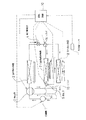
図1は、本発明の空気調和装置に係る第1の実施の形態の構成図である。ここで実線による接続は冷媒の流れ、破線による接続は、制御信号の流れを示す。圧縮機1からの冷媒配管は、四方弁2を経由して室内熱交換器3に接続される。室内熱交換器3からの冷媒配管は電子膨張弁4を経由した後、二方向に分岐し、一方は二方弁5(第1の開閉弁)を経由して石油冷媒加熱機7に接続され、他方は二方弁6(第2の開閉弁)を経由して室外熱交換器8に接続される。石油冷媒加熱機7からの冷媒配管は、圧縮機1に接続され、室外熱交換器8からの冷媒配管は、四方弁2および逆止弁9を経由して圧縮機1に戻る。また、二方弁6と圧縮機1との間にキャピラリチューブ12および二方弁13が接続されている。運転制御部10は、外気温センサ11からの外気温信号に応じて、運転制御を行う。
【0040】
次に運転制御部10の運転制御動作を説明する。装置起動後、石油冷媒加熱機7の燃焼用気化器の温度がヒータ予熱によって設定温度に達すると、冷媒回収運転を開始する。冷媒回収は、冷媒が冷媒配管を実線矢印方向に流れるように四方弁2を設定し、二方弁5,6を閉じて、圧縮機1を運転し、石油冷媒加熱機7および室外熱交換器8に貯まっていた冷媒を室内熱交換器3および配管途中に回収する。冷媒回収を終了すると、二方弁5を開け、燃料である灯油の着火が行われ、石油冷媒加熱による暖房運転を開始する。石油冷媒加熱機7の入口および出口の温度(あるいは圧縮機1の吸い込み温度)をセンサで検出し、石油冷媒加熱機7で蒸発した冷媒の過熱度が一定になるように、電子膨張弁4にて冷媒の流れを制御する。
【0041】
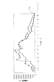
ところで図2は、ある寒冷地における従来の灯油を用いた石油冷媒加熱単独運転およびヒートポンプ単独運転の外気温度に対する暖房運転費の一例を示したものである。この場合、年間の総暖房費は、各外気温度1℃ごとの暖房費を積分して求められ、石油冷媒加熱単独運転の場合で約50,000円、ヒートポンプ単独運転の場合で約54,000円である。
【0042】
年間暖房費は、寒冷地における外気温度とその継続時間、建物負荷、ヒートポンプおよび冷媒加熱機器の性能などに左右されるため、より暖房費算出の精度を高めるためには、あらかじめ設置場所や機器性能を考慮した暖房運転費の算出が必要である。暖房運転費の算出方法としては、例えばJIS C 9612に基づいた方法、あるいは、公に認められている空調負荷を考慮した計算方法でもよいが、機器性能はより精度を高めるため、外気温度を変えた暖房性能試験結果を用いる方法がより良いと考えられる。
【0043】
図2の例の場合、ヒートポンプ運転では外気温に応じて暖房能力が左右されるので、外気温度が1℃以上ではヒートポンプ運転、1℃未満では冷媒加熱運転の方が暖房費が安くなる。従って、維持費用を最小化するためには、1℃でヒートポンプ運転と冷媒加熱運転とを切り替えるハイブリッド運転を行えば、ランニングコストを低減できる。ただし、ヒートポンプ運転では、外気温が5℃付近で室外熱交換器に着霜が始まり、除霜運転を必要とするので、暖房の快適性を考慮した場合、除霜運転を行う間の暖房運転の休止は、できるだけ避けた方が望ましい。したがって、ハイブリッド運転では、暖房の快適性を考慮して切り替え温度を1℃ではなく、多少高めに設定して暖房の休止を無くし、ある程度のランニングコスト低減を可能とする。
【0044】
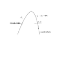
そこで、本実施の形態では、ヒートポンプ運転における実際の着霜温度が約5℃であることを考慮して、図3に示すように運転を開始した際に、外気温度が低いときは冷媒加熱運転を行い、その後、外気温度が上昇して7℃になるとヒートポンプ運転に切り替える。外気温度が7℃以上のときはヒートポンプ運転を継続して行い、外気温度が下がり5℃以下になると冷媒加熱運転に切り替える。外気温度の上昇時と下降時とで運転の切り替え温度を変えることによって、制御の安定性と快適性とを向上させることができる。
【0045】
図1に示す本実施の形態の空気調和装置では、暖房運転起動時、外気温に関係なく冷媒加熱運転を優先して立ち上げる。このとき、外気温センサ11の示す外気温度が7℃以下では、冷媒加熱運転をそのまま継続する。一方、暖房運転を立ち上げたとき、すでに外気温度が7℃を越えている場合は、起動から一定時間後に冷媒加熱運転からヒートポンプ運転に切り替える。その運転切り替えは、圧縮機1の運転を継続したまま、石油冷媒加熱機7の燃焼を停止後、二方弁5を閉じ、二方弁6を開け、冷媒の流れを室外熱交換器8側に切り替える。室外熱交換器8の入口および出口の温度(あるいは圧縮機1の吸い込み温度)をセンサで検出し、室外熱交換器8で蒸発した冷媒の過熱度が一定になるように、電子膨張弁4にて冷媒の流量を制御する。
【0046】
ヒートポンプ運転時に、着霜検出器(図示せず)にて室外熱交換器8の着霜を検出したら、二方弁13を開いて高温の圧縮機吐出ガスを室外熱交換器8の入口に戻し、除霜運転を行う。
【0047】
外気温が低下し、5℃以下になった場合、ヒートポンプ運転から冷媒加熱運転に切り替える。その運転切り替えは、起動時の制御とほぼ同様である。すなわち、圧縮機1を運転中に、二方弁5および二方弁6を閉じ、石油冷媒加熱機7および室外熱交換器8に溜まっていた冷媒を、室内熱交換器3および配管途中に回収する。石油冷媒加熱機7の燃焼用気化器は、予熱時間を考慮し、冷媒回収の開始と同時、あるいはそれ以前に、ヒータによって予熱を開始する。
【0048】
冷媒回収が終了すると、二方弁5を開ける。冷媒回収終了後、石油冷媒加熱機7の燃焼用気化器の温度が設定温度に達していると、燃料である灯油の着火が行われ、石油冷媒加熱による暖房運転を開始する。石油冷媒加熱機7の入口および出口の温度をセンサで検出し、石油冷媒加熱機7で蒸発した冷媒の過熱度が一定になるように、電子膨張弁4にて冷媒の流量を制御する。
【0049】
このヒートポンプから冷媒加熱への運転切り替えが、起動時の冷媒加熱運転と比べて異なる点は、前者が冷媒回収時にも、室内機の送風機が室内熱交換器温度に応じて回転し、暖房運転を継続することである。
【0050】
本実施の形態では、暖房起動時に冷媒加熱運転を行うが、石油残量検出器(図示せず)が石油残量が少なくなったことを検出したときは、ヒートポンプ運転を行う。また、石油冷媒加熱機7に故障が生じ冷媒加熱運転を行うことが困難な場合は、緊急避難運転として強制的にヒートポンプ運転を行う。強制運転指示は、リモコンあるいは室内機に備えたスイッチを操作することによって行う。低外気温度で高多湿時に、室外熱交換器8に着霜が生じた場合の除霜は、二方弁13を開いて高温の圧縮機吐出ガスを室外熱交換器8の入口に戻して除霜運転を行う。
【0051】
なお、この除霜運転は、四方弁2を反転させて高温の圧縮機吐出ガスを室外熱交換器8へ戻す構成に変更しても良い。この場合は、図1に示すキャピラリチューブ12、二方弁13およびそれらを接続する配管を無くすことができるので、サイクル構成の簡素化並びにコスト低減が図れる。
【0052】
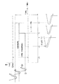
次に図4は、本発明の空気調和装置に係る第2の実施の形態の構成図である。ここで実線による接続は冷媒の流れ、破線による接続は、制御信号の流れを示す。圧縮機1からの冷媒配管は、四方弁2を経由して室内熱交換器3に接続される。室内熱交換器3からの冷媒配管は電子膨張弁4を経由した後、三方弁14に接続され、この三方弁14から分岐された冷媒配管は、一方が石油冷媒加熱機7に接続され、他方が室外熱交換器8に接続される。石油冷媒加熱機7からの冷媒配管は、三方弁15に接続され、この三方弁15からから分岐された冷媒配管は、一方が圧縮機1に接続され、他方が三方弁14からの配管と共に室外熱交換器8に接続される。室外熱交換器8からの冷媒配管は、四方弁2および逆止弁9を経由して圧縮機1に戻る。運転制御部10は、外気温センサ11からの外気温信号に応じて、運転制御を行う。
【0053】
次に運転制御部10の運転制御動作を説明する。装置起動後、まず冷媒が冷媒配管を実線矢印方向に流れるように四方弁2を設定し、三方弁14を電子膨張弁4から石油冷媒加熱機7に冷媒が流れるように設定し、三方弁15を石油冷媒加熱機7から室外熱交換器8に冷媒が流れるように設定する。そして石油冷媒加熱機7の燃焼用気化器はヒータによって予熱を開始する。石油冷媒加熱機7の燃焼用気化器の温度が設定温度に達すると、圧縮機1を運転し、燃料である灯油の着火が行われ、石油冷媒加熱による暖房運転を開始する。石油冷媒加熱機7の入口および出口の温度をセンサで検出し、石油冷媒加熱機7で蒸発した冷媒の過熱度が一定になるように、電子膨張弁4にて冷媒の流れを制御する。過熱度制御を開始した一定時間後に、三方弁15を切り替え、石油冷媒加熱機7から圧縮機1に冷媒の流れを変えて、室外熱交換器8側を閉じる。このようにして本実施例では、起動時の冷媒回収運転を必要としない。
【0054】
本実施の形態の空気調和装置では、暖房運転起動時、外気温に関係なく冷媒加熱運転を優先して立ち上げる。このとき、外気温センサ11の示す外気温度が7℃以下では、冷媒加熱運転をそのまま継続する。一方、暖房運転を立ち上げたとき、すでに外気温度が7℃を越えている場合は、起動から一定時間後に冷媒加熱運転からヒートポンプ運転に切り替える。その運転切り替えは、圧縮機1の運転を継続したまま、石油冷媒加熱機7の燃焼を停止後、三方弁14を切り替え、石油冷媒加熱機7側を閉じて、電子膨張弁4から室外熱交換器8側に冷媒を流す。室外熱交換器8の入口および出口の温度をセンサで検出し、室外熱交換器8で蒸発した冷媒の過熱度が一定になるように、電子膨張弁4にて冷媒の流量を制御する。
【0055】
ヒートポンプ運転時に、着霜検出器(図示せず)にて室外熱交換器8の着霜を検出したら、三方弁14を切り替え、電子膨張弁4から石油冷媒加熱機7側に冷媒を流し、石油燃焼を行う。同時に三方弁15を石油冷媒加熱機7から室外熱交換器8に流れるように設定する。石油冷媒加熱機7にて加熱され蒸発した高温の冷媒は、着霜した室外熱交換器8を通り、除霜を行いながら圧縮機1に吸引される。電子膨張弁4は、石油冷媒加熱機7で蒸発した冷媒の過熱度が一定となるように、石油冷媒加熱機7の入口および出口の温度をセンサで検出して制御されるが、圧縮機1の入口での冷媒の液バック量をできるだけ小さくするため、過熱度設定温度は通常の冷媒加熱運転の場合より大きくする。この除霜運転の特徴は、除霜運転を行いながら連続暖房運転をできることである。除霜が終了したら、三方弁14および15を切り替え、通常のヒートポンプ運転に戻る。
【0056】
外気温が低下し、5℃以下になった場合、ヒートポンプ運転から冷媒加熱運転に切り替える。その運転切り替えは、起動時の制御とほぼ同様である。すなわち、三方弁14を電子膨張弁4から石油冷媒加熱機7側に冷媒を流すように切り替え、三方弁15を石油冷媒加熱機7から室外熱交換器8側に冷媒が流れるように切り替える。
【0057】
石油冷媒加熱機7の燃焼用気化器は、ヒートポンプ運転から冷媒加熱運転に切り替える前に予熱終了できるように、ヒータによる予熱を開始する。冷媒回路の切り替えが終了し、石油冷媒加熱機7の燃焼用気化器の温度が設定温度に達すると、燃料である灯油の着火が行われ、石油冷媒加熱による暖房運転を開始する。石油冷媒加熱機7の入口および出口の温度をセンサで検出し、石油冷媒加熱機7で蒸発した冷媒の過熱度が一定になるように、電子膨張弁4にて冷媒の流れを制御する。過熱度制御を開始した一定時間後に、三方弁15を切り替え、石油冷媒加熱機7から圧縮機1に冷媒の流れを変えて、室外熱交換器8側を閉じる。このようにして本実施例では、運転切り替え時の冷媒回収運転を必要としない。このため、暖房能力の落ち込みが非常に小さく、快適性を向上できる。
【0058】
本実施の形態では、暖房起動時に冷媒加熱運転を行うが、石油残量検出器(図示せず)が石油残量が少なくなったことを検出したときは、ヒートポンプ運転を行う。また、石油冷媒加熱機7に故障が生じ冷媒加熱運転を行うことが困難な場合は、緊急避難運転として強制的にヒートポンプ運転を行う。この場合、三方弁14を切り替え、石油冷媒加熱機7側を閉じて、電子膨張弁4から室外熱交換器8側に冷媒を流す。同時に三方弁15を切り替え、石油冷媒加熱機7と室外熱交換器8の間は閉じる。室外熱交換器8の入口および出口の温度をセンサで検出し、室外熱交換器8で蒸発した冷媒の過熱度が一定になるように、電子膨張弁4にて冷媒の流量を制御する。
【0059】
強制運転指示は、リモコンあるいは室内機に備えたスイッチを操作することによって行う。低外気温度で高多湿時に、室外熱交換器8に着霜が生じた場合の除霜は、四方弁2を反転させて高温の圧縮機吐出ガスを室外熱交換器8の入口に戻す除霜運転を行う。
【0060】
次に第3の実施の形態について説明する。
本実施の形態では、外気温のみならず、空調に必要とされる暖房能力に応じてヒートポンプ運転または冷媒加熱運転のどちらか一方を選択して運転制御することを特徴としている。なお、本実施の形態におけるサイクル構成は図1に示すものと同一であるので、その構成の説明を省略すると共に、その作用につき図5を用いて説明する。
【0061】
図5は、横軸が外気温度(℃)を、縦軸が空調に必要とする暖房能力(kW)を示し、外気温と暖房能力に応じてヒートポンプ運転または冷媒加熱運転のどちらを選択して運転制御を行うことを示す説明図である。
【0062】
本実施の形態の空気調和装置では、暖房運転起動時、外気温に関係なく冷媒加熱運転を優先して立ち上げる。このとき、例えば、外気温が4℃の場合で、空調に必要とされる暖房能力が最大のQmaxであると判断されたとき、図5に示すように、暖房能力はQ1よりも大きいので、暖房能力Qmaxによる冷媒加熱運転を行う。空調に必要とする暖房能力は部屋から検出される室温と設定温度との差に基づいて求められる。すなわち、室温と設定温度との差が大きい場合は、必要とする暖房能力が高く設定される。ここで、暖房能力Qmaxを得るには、石油燃焼量を制御することで行われる。
【0063】
外気温が4℃のまま、冷媒加熱運転を継続した後、部屋の温度が上昇して必要とされる暖房能力が徐々に減少し、Q1より下回るときはヒートポンプ運転に切り替える。このとき、ヒートポンプ運転での暖房能力は圧縮機1に接続されるインバータ電源(図示省略)の制御周波数により、圧縮機1の回転数を制御することで行われる。そして、ヒートポンプ運転を継続中に部屋のドアを開ける等して部屋の温度が急激に下がり、空調を必要とする暖房能力がQ2を越えると再び冷媒加熱運転に切り替えて運転制御を行う。
【0064】
また、暖房運転起動時、冷媒加熱運転で立ち上げたとき、外気温が4℃の場合で、部屋から検出される温度が設定温度に近く、空調に必要とされる暖房能力が低く、必要とする暖房能力がQ1よりも小さい場合は、一定時間後にヒートポンプ運転に切り替えるように制御される。
【0065】
一方、暖房運転時において、外気温が4℃から下がって−1℃を下回った場合は、図5に示すように冷媒加熱運転に切り替えて運転制御すると共に、その後上昇して3℃を越える場合は、再びヒートポンプ運転に切り替えて運転するように制御する。
【0066】
ここで、必要とする暖房能力に応じてヒートポンプ運転と冷媒加熱運転を切り替えるのは、ヒートポンプ運転では約0.7〜6.0kWの可変幅、冷媒加熱運転では約2.5〜6.6kWの可変幅と、ヒートポンプ運転の方が暖房能力を可変できる範囲が広く、特に、低い暖房能力域では、可変幅の広いヒートポンプ運転を選択すると運転効率が良くなり、しかも暖房の快適性を高めることができる。
【0067】
ところで、本実施の形態では、図6に示すように、空調に必要とする暖房能力(以下、要求能力という)が低く、Q1を下回る場合は、ヒートポンプ運転を行う。その後、要求能力が上昇してQ2を越えた時点で、ヒートポンプ運転から冷媒加熱運転に切り替える。この冷媒加熱運転に入った後は、要求能力がQ1を下回るまで、ヒートポンプ運転に入らないようにしている。したがって、要求能力の上昇時と下降時とで運転の切り替え能力を変えているので、制御の安定性と快適性を向上させることができる。
【0068】
このように、外気温のみならず、空調に必要とする暖房能力に応じてヒートポンプ運転と冷媒加熱運転を切り替えて運転制御するので、暖房ランニングコストを低減しつつ、快適性を向上できる。
【0069】
また、本実施の形態では、図5に示すように外気温度または暖房能力の切替点をそれぞれ3通りづつ設定し、特に、室外熱交換器に着霜が生じやすく、かつヒートポンプ運転の効率が悪くなる外気温の低い領域では冷媒加熱運転の比率を高めるように設定してあるので、きめの細かな室温制御を行え、暖房の快適性を大幅に向上できる。
【0070】
【発明の効果】
以上説明した通り、本発明の請求項1に記載の空気調和装置は、外気温センサからの外気温信号に応じて、ヒートポンプ運転と冷媒加熱運転とを切り替えるので、低外気温時の高暖房能力の実現および暖房時のランニングコストを低減し、かつ快適性を向上できると共に、運転時に応じて冷媒の流路を切り替えるので、装置の配管を簡素化でき、運転制御の安定性を向上する。
【0073】
また、第1の開閉弁と第2の開閉弁による開又は閉による組合せ制御によって、冷媒を室内機側に回収した後、又は石油加熱機の燃焼停止後にヒートポンプ運転から冷媒加熱運転に切り替えるので、簡素な配管で冷媒を確保して運転切り替えでき、冷凍サイクルの安定性を向上できる。
【0077】
本発明の請求項2に記載の空気調和装置は、着霜を検出した際、除霜運転を行うので、室外熱交換器の着霜を解消でき、安定したヒートポンプ運転を行うことができる。また、ヒートポンプ運転時に着霜を検出した場合でも、室外熱交換器と石油冷媒加熱機とを直列接続として、除霜運転を行うので、室外熱交換器に着霜したときでも、連続暖房運転によって、暖房快適性を維持しながら除霜できる。
【0079】
本発明の請求項3に記載の空気調和装置は、石油冷媒加熱機から室外熱交換器に冷媒を流して冷媒加熱運転を行った後、石油冷媒加熱機から直接圧縮機に冷媒を流すことによってヒートポンプ運転から冷媒加熱運転に切り替えるので、冷媒回収をせずに運転の切り替えができ、暖房快適性を向上する。
【図面の簡単な説明】
【図1】本発明の空気調和装置に係る第1の実施の形態を示す構成図である。
【図2】外気温度に対する暖房運転費の一例を示す図である。
【図3】外気温度の上昇時と下降時とで運転の切り替え温度を示す図である。
【図4】本発明の空気調和装置に係る第2の実施の形態を示す構成図である。
【図5】本発明の空気調和装置に係る第3の実施の形態を示す作用説明図である。
【図6】暖房能力の上昇時と下降時とで運転を切り替える説明図である。
【符号の説明】
1…圧縮機,2…四方弁,3…室内熱交換器,4…電子膨張弁,5…二方弁,6…二方弁,7…石油冷媒加熱機,8…室外熱交換器,9…逆止弁,10…運転制御部,11…外気温センサ,12…キャピラリチューブ,13…二方弁,14…三方弁,15…三方弁。[0001]
BACKGROUND OF THE INVENTION
The present invention relates to an air conditioner including an oil refrigerant heater that heats a refrigerant during heating.
[0002]
[Prior art]
In recent years, in the air-conditioner market mainly for heat pump type, many models with more advanced energy saving and higher heating have been released.
[0003]
With regard to energy saving, efforts are being made to improve the performance of compressors, blowers, heat exchangers, etc., reduce the difference between the evaporation temperature and the condensation temperature, and reduce the input of the refrigeration cycle.
[0004]
In high heating, it has become possible to demonstrate high heating capacity even at low outside temperatures by using heat storage, using liquid injection, and improving the efficiency of compressor input.
[0005]
On the other hand, in a cold district where the outside air temperature is low in winter, a refrigerant heating type air conditioner that performs heating operation by heating and evaporating the refrigerant with a combustion heat source such as oil or gas has appeared on the market.
[0006]
[Problems to be solved by the invention]
However, as long as the heat pump is based on the principle of pumping up and using an air heat source, the evaporation temperature of the refrigerant must be equal to or lower than the outside air temperature, and when the outside air temperature is low, frost formation or a decrease in the circulation rate of the refrigerant Problems such as reduced heating capacity remain.
[0007]
In the refrigerant heating type, a compressor is generally used to circulate the heated and evaporated refrigerant. Since the input of the compressor as a gas pump is relatively high, it can exhibit high heating capacity, but the maintenance cost is never Not cheap. In particular, in the refrigerant heating method by gas combustion, the gas cost is expensive and the electricity cost is also required. Therefore, the refrigerant heating method using oil as fuel instead of gas can reduce the maintenance cost relatively.
[0008]
On the other hand, under conditions where the outside air temperature is high, the heat pump type can sufficiently exhibit the heating capacity and the heating cost is lower than the refrigerant heating method using gas or petroleum fuel.
[0009]
The present invention takes advantage of the features of the heat pump type and the petroleum refrigerant heating type, and in the heating cycle, switching between the heat pump operation by the air heat source and the refrigerant heating operation by the petroleum heat source in consideration of economy and comfort, An object of the present invention is to provide an air-conditioning apparatus that reduces the running cost and improves comfort.
[0010]
[Means for Solving the Problems]
In order to solve the above-described problem, an air conditioner according to
An outdoor heat exchanger for exchanging heat between the outdoor air and the refrigerant;
An indoor heat exchanger for exchanging heat between the refrigerant and room air;
A compressor for circulating the refrigerant;
First and second on-off valves that switch the refrigerant circulation path to either the outdoor heat exchanger or the petroleum refrigerant heater;
An outside air temperature sensor for detecting outside air temperature,
According to an outside air temperature signal from the outside air temperature sensor, the first and second on-off valves are controlled to open and close, and when the outside air temperature is higher than a predetermined value, the refrigerant circulation path is switched to an outdoor heat exchanger to perform heat pump operation. On the other hand, when the outside air temperature is lower than the predetermined value, it comprises an operation control means for switching the refrigerant circulation path to the petroleum refrigerant heater and performing the refrigerant heating operation ,
During heat pump operation, the first on-off valve is closed, the second on-off valve is opened, and the circuit is switched to a circulation path through which refrigerant flows to the outdoor heat exchanger,
During the refrigerant heating operation, the first on-off valve is opened and the second on-off valve is closed to switch to a circulation path through which the refrigerant flows through the petroleum refrigerant heater ,
In order to maintain the refrigerant heating operation from the heat pump operation, after the first and second on-off valves are closed and the refrigerant is collected on the indoor heat exchanger side, the first on-off valve is opened and the refrigerant is supplied to the petroleum refrigerant heater. Switch to the circulation path,
From the refrigerant heating operation to the heat pump operation, after the combustion of the petroleum refrigerant heater is stopped, the first on-off valve is closed and the second on-off valve is opened to switch to the circulation path through which the refrigerant flows to the outdoor heat exchanger. Features.
[0011]
With the above configuration, since the heat pump operation and the refrigerant heating operation are switched according to the outside air temperature signal from the outside air temperature sensor, it is possible to realize a high heating capacity at a low outside air temperature and to reduce a running cost at the time of heating. At the same time, since the refrigerant flow path is switched according to the operation, piping of the apparatus can be simplified.
[0017]
In addition, the refrigerant is recovered from the indoor unit by the combination control of opening and closing by the first on-off valve and the second on-off valve , or after the oil refrigerant heater stops combustion, the heat pump operation is changed to the refrigerant heating operation. Therefore, the refrigerant can be secured with a simple pipe and the operation can be switched smoothly .
[0024]
In the air conditioner according to
[0025]
With the above configuration, when frost is detected, defrosting operation control is performed, so that frost formation on the outdoor heat exchanger can be eliminated. Also, even when frost formation is detected during heat pump operation, the outdoor heat exchanger and the petroleum refrigerant heater are connected in series to perform the defrost operation, so even when the outdoor heat exchanger is frosted, continuous heating operation is performed. Can be maintained.
[0028]
The air conditioner according to
[0029]
With the above configuration, since the refrigerant is supplied from the petroleum refrigerant heater to the outdoor heat exchanger and the refrigerant heating operation is performed, the refrigerant is directly supplied from the petroleum refrigerant heater to the compressor, thereby switching from the heat pump operation to the refrigerant heating operation. The operation can be switched without collecting the refrigerant.
[0038]
DETAILED DESCRIPTION OF THE INVENTION
Hereinafter, embodiments of the present invention will be described in detail with reference to the drawings.
[0039]
FIG. 1 is a configuration diagram of a first embodiment according to an air conditioner of the present invention. Here, the connection by the solid line indicates the flow of the refrigerant, and the connection by the broken line indicates the flow of the control signal. The refrigerant pipe from the
[0040]
Next, the operation control operation of the
[0041]
FIG. 2 shows an example of the heating operation cost with respect to the outside air temperature in the petroleum refrigerant heating single operation and the heat pump single operation using the conventional kerosene in a cold region. In this case, the annual total heating cost is obtained by integrating the heating costs for each outside air temperature of 1 ° C., about 50,000 yen in the case of oil refrigerant heating single operation, and about 54,000 in the case of heat pump single operation. Yen.
[0042]
The annual heating cost depends on the outside air temperature and its duration in cold regions, the building load, the performance of heat pumps and refrigerant heating equipment, etc. It is necessary to calculate the heating operation cost considering the above. As a method for calculating the heating operation cost, for example, a method based on JIS C 9612 or a calculation method considering an air-conditioning load accepted publicly may be used. However, in order to improve the accuracy of the equipment performance, the outside air temperature is changed. It is considered that the method using the heating performance test result is better.
[0043]
In the case of the example in FIG. 2, since the heating capacity depends on the outside air temperature in the heat pump operation, the heat cost is cheaper in the heat pump operation when the outside air temperature is 1 ° C. or higher, and the refrigerant heating operation is less than 1 ° C. Therefore, in order to minimize the maintenance cost, the running cost can be reduced by performing the hybrid operation that switches between the heat pump operation and the refrigerant heating operation at 1 ° C. However, in the heat pump operation, the outdoor heat exchanger starts frosting when the outside air temperature is around 5 ° C. and requires a defrosting operation. Therefore, when considering the comfort of heating, the heating operation during the defrosting operation is performed. It is desirable to avoid pauses as much as possible. Therefore, in the hybrid operation, the switching temperature is set to be slightly higher than 1 ° C. in consideration of the comfort of heating, so that the heating is not stopped and the running cost can be reduced to some extent.
[0044]
Therefore, in the present embodiment, considering that the actual frosting temperature in the heat pump operation is about 5 ° C., when the operation is started as shown in FIG. After that, when the outside air temperature rises to 7 ° C., the operation is switched to the heat pump operation. When the outside air temperature is 7 ° C. or higher, the heat pump operation is continued, and when the outside air temperature falls to 5 ° C. or below, the operation is switched to the refrigerant heating operation. Control stability and comfort can be improved by changing the operation switching temperature between when the outside air temperature rises and when it falls.
[0045]
In the air conditioning apparatus according to the present embodiment shown in FIG. 1, when the heating operation is started, the refrigerant heating operation is preferentially started up regardless of the outside air temperature. At this time, when the outside air temperature indicated by the outside air temperature sensor 11 is 7 ° C. or lower, the refrigerant heating operation is continued as it is. On the other hand, when the heating operation is started, if the outside air temperature has already exceeded 7 ° C., the refrigerant heating operation is switched to the heat pump operation after a certain time from the start. As for the operation switching, the combustion of the petroleum refrigerant heater 7 is stopped while the operation of the
[0046]
When frosting of the
[0047]
When outside air temperature falls and becomes 5 degrees C or less, it switches from heat pump operation to refrigerant | coolant heating operation. The operation switching is almost the same as the control at startup. That is, while the
[0048]
When the refrigerant recovery is completed, the two-
[0049]
The switching from heat pump to refrigerant heating is different from the refrigerant heating operation at the start-up. Even when the former is collecting the refrigerant, the blower of the indoor unit rotates according to the indoor heat exchanger temperature, and the heating operation is performed. It is to continue.
[0050]
In the present embodiment, the refrigerant heating operation is performed at the time of heating activation, but when the remaining amount of oil detector (not shown) detects that the amount of remaining oil has decreased, the heat pump operation is performed. In addition, when a failure occurs in the petroleum refrigerant heater 7 and it is difficult to perform the refrigerant heating operation, the heat pump operation is forcibly performed as an emergency evacuation operation. The forced operation instruction is performed by operating a switch provided on the remote controller or the indoor unit. When defrosting occurs in the
[0051]
The defrosting operation may be changed to a configuration in which the high-temperature compressor discharge gas is returned to the
[0052]
Next, FIG. 4 is a block diagram of a second embodiment according to the air conditioning apparatus of the present invention. Here, the connection by the solid line indicates the flow of the refrigerant, and the connection by the broken line indicates the flow of the control signal. The refrigerant pipe from the
[0053]
Next, the operation control operation of the
[0054]
In the air conditioning apparatus of the present embodiment, when the heating operation is started, the refrigerant heating operation is preferentially started regardless of the outside air temperature. At this time, when the outside air temperature indicated by the outside air temperature sensor 11 is 7 ° C. or lower, the refrigerant heating operation is continued as it is. On the other hand, when the heating operation is started, if the outside air temperature has already exceeded 7 ° C., the refrigerant heating operation is switched to the heat pump operation after a certain time from the start. As for the operation switching, after the combustion of the petroleum refrigerant heater 7 is stopped while the operation of the
[0055]
When frost formation of the
[0056]
When outside air temperature falls and becomes 5 degrees C or less, it switches from heat pump operation to refrigerant | coolant heating operation. The operation switching is almost the same as the control at startup. That is, the three-
[0057]
The combustion vaporizer of the petroleum refrigerant heater 7 starts preheating with a heater so that preheating can be completed before switching from the heat pump operation to the refrigerant heating operation. When the switching of the refrigerant circuit is completed and the temperature of the combustion vaporizer of the petroleum refrigerant heater 7 reaches the set temperature, the kerosene as the fuel is ignited and the heating operation by heating the petroleum refrigerant is started. The temperature of the inlet and outlet of the petroleum refrigerant heater 7 is detected by a sensor, and the flow of the refrigerant is controlled by the electronic expansion valve 4 so that the degree of superheat of the refrigerant evaporated by the petroleum refrigerant heater 7 becomes constant. After a certain period of time when the superheat control is started, the three-way valve 15 is switched, the refrigerant flow is changed from the petroleum refrigerant heater 7 to the
[0058]
In the present embodiment, the refrigerant heating operation is performed at the time of heating activation, but when the remaining amount of oil detector (not shown) detects that the amount of remaining oil has decreased, the heat pump operation is performed. In addition, when a failure occurs in the petroleum refrigerant heater 7 and it is difficult to perform the refrigerant heating operation, the heat pump operation is forcibly performed as an emergency evacuation operation. In this case, the three-
[0059]
The forced operation instruction is performed by operating a switch provided on the remote controller or the indoor unit. When the
[0060]
Next, a third embodiment will be described.
The present embodiment is characterized in that operation control is performed by selecting either the heat pump operation or the refrigerant heating operation according to not only the outside air temperature but also the heating capacity required for air conditioning. Since the cycle configuration in the present embodiment is the same as that shown in FIG. 1, the description of the configuration is omitted and the operation will be described with reference to FIG.
[0061]
In FIG. 5, the horizontal axis indicates the outside air temperature (° C.), the vertical axis indicates the heating capacity (kW) required for air conditioning, and either the heat pump operation or the refrigerant heating operation is selected according to the outside air temperature and the heating capacity. It is explanatory drawing which shows performing operation control.
[0062]
In the air conditioning apparatus of the present embodiment, when the heating operation is started, the refrigerant heating operation is preferentially started regardless of the outside air temperature. At this time, for example, when the outside air temperature is 4 ° C. and it is determined that the heating capacity required for air conditioning is the maximum Qmax, as shown in FIG. 5, the heating capacity is larger than Q1, The refrigerant heating operation is performed with the heating capacity Qmax. The heating capacity necessary for air conditioning is obtained based on the difference between the room temperature detected from the room and the set temperature. That is, when the difference between the room temperature and the set temperature is large, the required heating capacity is set high. Here, the heating capacity Qmax is obtained by controlling the amount of oil combustion.
[0063]
After the refrigerant heating operation is continued while the outside air temperature remains at 4 ° C., the room temperature rises and the required heating capacity gradually decreases, and when it falls below Q1, the operation is switched to the heat pump operation. At this time, the heating capacity in the heat pump operation is performed by controlling the rotation speed of the
[0064]
In addition, when the heating operation is started up and the refrigerant heating operation is started, the temperature detected from the room is close to the set temperature when the outside air temperature is 4 ° C., and the heating capacity required for air conditioning is low. When the heating capacity to be performed is smaller than Q1, control is performed so as to switch to the heat pump operation after a certain time.
[0065]
On the other hand, when the outside air temperature drops below 4 ° C. and falls below −1 ° C. during the heating operation, the operation is controlled by switching to the refrigerant heating operation as shown in FIG. Controls to switch to heat pump operation again.
[0066]
Here, the heat pump operation and the refrigerant heating operation are switched according to the required heating capacity because the heat pump operation has a variable width of about 0.7 to 6.0 kW and the refrigerant heating operation of about 2.5 to 6.6 kW. The variable range and heat pump operation have a wider range in which the heating capacity can be varied, especially in the low heating capacity range, selecting a heat pump operation with a wide variable width will improve operating efficiency and increase the comfort of heating. it can.
[0067]
By the way, in this Embodiment, as shown in FIG. 6, when the heating capability (henceforth required capability) required for an air conditioning is low and is less than Q1, heat pump driving | operation is performed. Thereafter, when the required capacity rises and exceeds Q2, the heat pump operation is switched to the refrigerant heating operation. After entering the refrigerant heating operation, the heat pump operation is not entered until the required capacity falls below Q1. Therefore, since the operation switching ability is changed between when the required capacity increases and when the required capacity decreases, the stability and comfort of control can be improved.
[0068]
As described above, since the operation is controlled by switching between the heat pump operation and the refrigerant heating operation according to not only the outside air temperature but also the heating capacity required for air conditioning, the comfort can be improved while reducing the heating running cost.
[0069]
Further, in this embodiment, as shown in FIG. 5, three switching points of the outside air temperature or the heating capacity are set respectively, and in particular, the outdoor heat exchanger is likely to be frosted and the efficiency of the heat pump operation is poor. Since the ratio of the refrigerant heating operation is set so as to increase in the low outside air temperature range, it is possible to perform fine room temperature control and greatly improve the comfort of heating.
[0070]
【The invention's effect】
As described above, since the air conditioning apparatus according to
[0073]
In addition, since the refrigerant is recovered to the indoor unit side by the combination control by opening or closing by the first on-off valve and the second on-off valve , or after the oil heater stops combustion, the heat pump operation is switched to the refrigerant heating operation. The refrigerant can be secured with simple piping and the operation can be switched, and the stability of the refrigeration cycle can be improved.
[0077]
Since the air conditioning apparatus according to
[0079]
In the air conditioner according to
[Brief description of the drawings]
FIG. 1 is a configuration diagram illustrating a first embodiment of an air conditioner according to the present invention.
FIG. 2 is a diagram illustrating an example of a heating operation cost with respect to an outside air temperature.
FIG. 3 is a diagram showing an operation switching temperature between when the outside air temperature rises and when it falls.
FIG. 4 is a configuration diagram showing a second embodiment according to the air-conditioning apparatus of the present invention.
FIG. 5 is an operation explanatory view showing a third embodiment of the air conditioner of the present invention.
FIG. 6 is an explanatory diagram for switching operation between when the heating capacity increases and when it decreases.
[Explanation of symbols]
DESCRIPTION OF
Claims (3)
室外空気と冷媒との熱交換を行う室外熱交換器と、
冷媒と室内空気との熱交換を行う室内熱交換器と、
冷媒を循環させる圧縮機と、
冷媒の循環路を前記室外熱交換器または石油冷媒加熱機のいずれかに切り替える第1,第2の開閉弁と、
外気温を検出する外気温センサと、
前記外気温センサからの外気温信号に応じて前記第1,第2の開閉弁を開閉制御すると共に外気温が所定値より高い場合は冷媒の循環路を室外熱交換器に切り替えてヒートポンプ運転とする一方、外気温が所定値より低い場合は冷媒の循環路を石油冷媒加熱機に切り替えて冷媒加熱運転とする運転制御手段とを具備し、
ヒートポンプ運転時には、前記第1の開閉弁を閉、第2の開閉弁を開として前記室外熱交換器に冷媒が流れる循環路に切り替え、
冷媒加熱運転時には、前記第1の開閉弁を開、第2の開閉弁を閉として前記石油冷媒加熱機に冷媒が流れる循環路に切り替え、
ヒートポンプ運転から冷媒加熱運転持には、前記第1,第2の開閉弁を閉じて室内熱交換器側に冷媒を回収した後、前記第1の開閉弁を開として前記石油冷媒加熱機に冷媒が流れる循環路に切り替え、
冷媒加熱運転からヒートポンプ運転時には、前記石油冷媒加熱機の燃焼停止後、前記第1の開閉弁を閉、第2の開閉弁を開として前記室外熱交換器に冷媒が流れる循環路に切り替えることを特徴とする空気調和装置。An oil refrigerant heater that burns oil and heats the refrigerant;
An outdoor heat exchanger for exchanging heat between the outdoor air and the refrigerant;
An indoor heat exchanger for exchanging heat between the refrigerant and room air;
A compressor for circulating the refrigerant;
First and second on-off valves that switch the refrigerant circulation path to either the outdoor heat exchanger or the petroleum refrigerant heater;
An outside air temperature sensor for detecting outside air temperature,
According to an outside air temperature signal from the outside air temperature sensor, the first and second on-off valves are controlled to open and close, and when the outside air temperature is higher than a predetermined value, the refrigerant circulation path is switched to an outdoor heat exchanger to perform heat pump operation. On the other hand, when the outside air temperature is lower than the predetermined value, it comprises an operation control means for switching the refrigerant circulation path to the petroleum refrigerant heater and performing the refrigerant heating operation ,
During heat pump operation, the first on-off valve is closed, the second on-off valve is opened, and the circuit is switched to a circulation path through which refrigerant flows to the outdoor heat exchanger,
During the refrigerant heating operation, the first on-off valve is opened and the second on-off valve is closed to switch to a circulation path through which the refrigerant flows through the petroleum refrigerant heater ,
In order to maintain the refrigerant heating operation from the heat pump operation, after the first and second on-off valves are closed and the refrigerant is collected on the indoor heat exchanger side, the first on-off valve is opened and the refrigerant is supplied to the petroleum refrigerant heater. Switch to the circulation path,
From the refrigerant heating operation to the heat pump operation, after the combustion of the petroleum refrigerant heater is stopped, the first on-off valve is closed and the second on-off valve is opened to switch to the circulation path through which the refrigerant flows to the outdoor heat exchanger. An air conditioner characterized.
Priority Applications (3)
| Application Number | Priority Date | Filing Date | Title |
|---|---|---|---|
| JP01077198A JP4046828B2 (en) | 1998-01-22 | 1998-01-22 | Air conditioner |
| KR1019990001739A KR100308093B1 (en) | 1998-01-22 | 1999-01-21 | Air conditioner |
| CN99101365A CN1227906A (en) | 1998-01-22 | 1999-01-22 | air conditioner |
Applications Claiming Priority (1)
| Application Number | Priority Date | Filing Date | Title |
|---|---|---|---|
| JP01077198A JP4046828B2 (en) | 1998-01-22 | 1998-01-22 | Air conditioner |
Publications (3)
| Publication Number | Publication Date |
|---|---|
| JPH11211195A JPH11211195A (en) | 1999-08-06 |
| JPH11211195A5 JPH11211195A5 (en) | 2005-06-23 |
| JP4046828B2 true JP4046828B2 (en) | 2008-02-13 |
Family
ID=11759607
Family Applications (1)
| Application Number | Title | Priority Date | Filing Date |
|---|---|---|---|
| JP01077198A Expired - Fee Related JP4046828B2 (en) | 1998-01-22 | 1998-01-22 | Air conditioner |
Country Status (1)
| Country | Link |
|---|---|
| JP (1) | JP4046828B2 (en) |
Cited By (1)
| Publication number | Priority date | Publication date | Assignee | Title |
|---|---|---|---|---|
| EP3553224A4 (en) * | 2016-12-07 | 2020-09-16 | LG Electronics Inc. -1- | DEVICE FOR TREATMENT OF DRESSES AND METHOD FOR CONTROLLING THEREOF |
Families Citing this family (3)
| Publication number | Priority date | Publication date | Assignee | Title |
|---|---|---|---|---|
| KR100318680B1 (en) * | 1998-04-20 | 2002-08-09 | 삼성전자 주식회사 | Air-conditioning and combined air conditioning |
| JP6384057B2 (en) * | 2014-02-03 | 2018-09-05 | ダイキン工業株式会社 | Air conditioning system |
| CN113266873B (en) * | 2021-06-21 | 2025-02-14 | 珠海格力电器股份有限公司 | Fresh air air conditioning system and control method thereof |
-
1998
- 1998-01-22 JP JP01077198A patent/JP4046828B2/en not_active Expired - Fee Related
Cited By (1)
| Publication number | Priority date | Publication date | Assignee | Title |
|---|---|---|---|---|
| EP3553224A4 (en) * | 2016-12-07 | 2020-09-16 | LG Electronics Inc. -1- | DEVICE FOR TREATMENT OF DRESSES AND METHOD FOR CONTROLLING THEREOF |
Also Published As
| Publication number | Publication date |
|---|---|
| JPH11211195A (en) | 1999-08-06 |
Similar Documents
| Publication | Publication Date | Title |
|---|---|---|
| CN110940055B (en) | An air conditioner heating and defrosting control method, device and air conditioner | |
| JP5121922B2 (en) | Air conditioning and hot water supply complex system | |
| JP5642207B2 (en) | Refrigeration cycle apparatus and refrigeration cycle control method | |
| CN109458683B (en) | Dry type radiation heat pump and unit type household air conditioner all-in-one machine and control method thereof | |
| CN212538209U (en) | Heat pump system, heat pump air conditioner comprising same and heat pump water heater | |
| CN103765133B (en) | Refrigerating circulatory device and the air conditioner possessing this refrigerating circulatory device | |
| CN112443999A (en) | Air conditioner | |
| CN109520170A (en) | A kind of net for air-source heat pump units with twin-stage supercooling and liquid pulse defrosting function | |
| JPS6155018B2 (en) | ||
| JP4046828B2 (en) | Air conditioner | |
| CN115164302A (en) | Air conditioning system | |
| JP2000028185A (en) | Air conditioner | |
| CN220287807U (en) | An ultra-low temperature heat pump system | |
| JP2005016881A (en) | Air conditioner | |
| JP2000028186A (en) | Air conditioner | |
| CN115264583B (en) | A multi-connection system and control method thereof | |
| CN218469277U (en) | Outdoor unit and air conditioner | |
| KR100308093B1 (en) | Air conditioner | |
| CN216080129U (en) | Air source heat pump and air conditioner | |
| JP2523534B2 (en) | Air conditioner | |
| JP4622901B2 (en) | Air conditioner | |
| JP3373904B2 (en) | Engine driven air conditioner | |
| CN115218352A (en) | System for improving heat performance of multi-connected air conditioner and control method thereof | |
| KR100764707B1 (en) | Heat pump air conditioner and its defrost mode control method | |
| JP2912811B2 (en) | Air conditioner |
Legal Events
| Date | Code | Title | Description |
|---|---|---|---|
| A521 | Written amendment |
Free format text: JAPANESE INTERMEDIATE CODE: A523 Effective date: 20040927 |
|
| A621 | Written request for application examination |
Free format text: JAPANESE INTERMEDIATE CODE: A621 Effective date: 20040927 |
|
| A131 | Notification of reasons for refusal |
Free format text: JAPANESE INTERMEDIATE CODE: A131 Effective date: 20070717 |
|
| A521 | Written amendment |
Free format text: JAPANESE INTERMEDIATE CODE: A523 Effective date: 20070903 |
|
| TRDD | Decision of grant or rejection written | ||
| A01 | Written decision to grant a patent or to grant a registration (utility model) |
Free format text: JAPANESE INTERMEDIATE CODE: A01 Effective date: 20071113 |
|
| A61 | First payment of annual fees (during grant procedure) |
Free format text: JAPANESE INTERMEDIATE CODE: A61 Effective date: 20071121 |
|
| FPAY | Renewal fee payment (event date is renewal date of database) |
Free format text: PAYMENT UNTIL: 20101130 Year of fee payment: 3 |
|
| R150 | Certificate of patent or registration of utility model |
Free format text: JAPANESE INTERMEDIATE CODE: R150 |
|
| S111 | Request for change of ownership or part of ownership |
Free format text: JAPANESE INTERMEDIATE CODE: R313111 |
|
| FPAY | Renewal fee payment (event date is renewal date of database) |
Free format text: PAYMENT UNTIL: 20101130 Year of fee payment: 3 |
|
| R350 | Written notification of registration of transfer |
Free format text: JAPANESE INTERMEDIATE CODE: R350 |
|
| LAPS | Cancellation because of no payment of annual fees |