EP3553035B1 - Herstellungsverfahren für glasfasergrundmaterial - Google Patents
Herstellungsverfahren für glasfasergrundmaterial Download PDFInfo
- Publication number
- EP3553035B1 EP3553035B1 EP17880292.2A EP17880292A EP3553035B1 EP 3553035 B1 EP3553035 B1 EP 3553035B1 EP 17880292 A EP17880292 A EP 17880292A EP 3553035 B1 EP3553035 B1 EP 3553035B1
- Authority
- EP
- European Patent Office
- Prior art keywords
- alkali metal
- kinds
- raw materials
- optical fiber
- metal salt
- Prior art date
- Legal status (The legal status is an assumption and is not a legal conclusion. Google has not performed a legal analysis and makes no representation as to the accuracy of the status listed.)
- Active
Links
Images




Classifications
-
- C—CHEMISTRY; METALLURGY
- C03—GLASS; MINERAL OR SLAG WOOL
- C03B—MANUFACTURE, SHAPING, OR SUPPLEMENTARY PROCESSES
- C03B37/00—Manufacture or treatment of flakes, fibres, or filaments from softened glass, minerals, or slags
- C03B37/01—Manufacture of glass fibres or filaments
- C03B37/012—Manufacture of preforms for drawing fibres or filaments
- C03B37/014—Manufacture of preforms for drawing fibres or filaments made entirely or partially by chemical means, e.g. vapour phase deposition of bulk porous glass either by outside vapour deposition [OVD], or by outside vapour phase oxidation [OVPO] or by vapour axial deposition [VAD]
- C03B37/01446—Thermal after-treatment of preforms, e.g. dehydrating, consolidating, sintering
-
- C—CHEMISTRY; METALLURGY
- C03—GLASS; MINERAL OR SLAG WOOL
- C03B—MANUFACTURE, SHAPING, OR SUPPLEMENTARY PROCESSES
- C03B37/00—Manufacture or treatment of flakes, fibres, or filaments from softened glass, minerals, or slags
- C03B37/01—Manufacture of glass fibres or filaments
- C03B37/012—Manufacture of preforms for drawing fibres or filaments
- C03B37/014—Manufacture of preforms for drawing fibres or filaments made entirely or partially by chemical means, e.g. vapour phase deposition of bulk porous glass either by outside vapour deposition [OVD], or by outside vapour phase oxidation [OVPO] or by vapour axial deposition [VAD]
- C03B37/018—Manufacture of preforms for drawing fibres or filaments made entirely or partially by chemical means, e.g. vapour phase deposition of bulk porous glass either by outside vapour deposition [OVD], or by outside vapour phase oxidation [OVPO] or by vapour axial deposition [VAD] by glass deposition on a glass substrate, e.g. by inside-, modified-, plasma- or plasma modified- chemical vapour deposition [ICVD, MCVD, PCVD, PMCVD], i.e. by thin layer coating on the inside or outside of a glass tube or on a glass rod
- C03B37/01807—Reactant delivery systems, e.g. reactant deposition burners
-
- C—CHEMISTRY; METALLURGY
- C03—GLASS; MINERAL OR SLAG WOOL
- C03B—MANUFACTURE, SHAPING, OR SUPPLEMENTARY PROCESSES
- C03B37/00—Manufacture or treatment of flakes, fibres, or filaments from softened glass, minerals, or slags
- C03B37/01—Manufacture of glass fibres or filaments
- C03B37/012—Manufacture of preforms for drawing fibres or filaments
- C03B37/014—Manufacture of preforms for drawing fibres or filaments made entirely or partially by chemical means, e.g. vapour phase deposition of bulk porous glass either by outside vapour deposition [OVD], or by outside vapour phase oxidation [OVPO] or by vapour axial deposition [VAD]
-
- C—CHEMISTRY; METALLURGY
- C03—GLASS; MINERAL OR SLAG WOOL
- C03B—MANUFACTURE, SHAPING, OR SUPPLEMENTARY PROCESSES
- C03B37/00—Manufacture or treatment of flakes, fibres, or filaments from softened glass, minerals, or slags
- C03B37/01—Manufacture of glass fibres or filaments
- C03B37/012—Manufacture of preforms for drawing fibres or filaments
- C03B37/014—Manufacture of preforms for drawing fibres or filaments made entirely or partially by chemical means, e.g. vapour phase deposition of bulk porous glass either by outside vapour deposition [OVD], or by outside vapour phase oxidation [OVPO] or by vapour axial deposition [VAD]
- C03B37/01466—Means for changing or stabilising the diameter or form of tubes or rods
- C03B37/01473—Collapsing
-
- C—CHEMISTRY; METALLURGY
- C03—GLASS; MINERAL OR SLAG WOOL
- C03B—MANUFACTURE, SHAPING, OR SUPPLEMENTARY PROCESSES
- C03B37/00—Manufacture or treatment of flakes, fibres, or filaments from softened glass, minerals, or slags
- C03B37/01—Manufacture of glass fibres or filaments
- C03B37/012—Manufacture of preforms for drawing fibres or filaments
- C03B37/014—Manufacture of preforms for drawing fibres or filaments made entirely or partially by chemical means, e.g. vapour phase deposition of bulk porous glass either by outside vapour deposition [OVD], or by outside vapour phase oxidation [OVPO] or by vapour axial deposition [VAD]
- C03B37/018—Manufacture of preforms for drawing fibres or filaments made entirely or partially by chemical means, e.g. vapour phase deposition of bulk porous glass either by outside vapour deposition [OVD], or by outside vapour phase oxidation [OVPO] or by vapour axial deposition [VAD] by glass deposition on a glass substrate, e.g. by inside-, modified-, plasma- or plasma modified- chemical vapour deposition [ICVD, MCVD, PCVD, PMCVD], i.e. by thin layer coating on the inside or outside of a glass tube or on a glass rod
-
- G—PHYSICS
- G02—OPTICS
- G02B—OPTICAL ELEMENTS, SYSTEMS OR APPARATUS
- G02B6/00—Light guides; Structural details of arrangements comprising light guides and other optical elements, e.g. couplings
- G02B6/02—Optical fibres with cladding with or without a coating
-
- G—PHYSICS
- G02—OPTICS
- G02B—OPTICAL ELEMENTS, SYSTEMS OR APPARATUS
- G02B6/00—Light guides; Structural details of arrangements comprising light guides and other optical elements, e.g. couplings
- G02B6/02—Optical fibres with cladding with or without a coating
- G02B6/036—Optical fibres with cladding with or without a coating core or cladding comprising multiple layers
-
- C—CHEMISTRY; METALLURGY
- C03—GLASS; MINERAL OR SLAG WOOL
- C03B—MANUFACTURE, SHAPING, OR SUPPLEMENTARY PROCESSES
- C03B2201/00—Type of glass produced
- C03B2201/06—Doped silica-based glasses
- C03B2201/07—Impurity concentration specified
-
- C—CHEMISTRY; METALLURGY
- C03—GLASS; MINERAL OR SLAG WOOL
- C03B—MANUFACTURE, SHAPING, OR SUPPLEMENTARY PROCESSES
- C03B2201/00—Type of glass produced
- C03B2201/06—Doped silica-based glasses
- C03B2201/07—Impurity concentration specified
- C03B2201/075—Hydroxyl ion (OH)
-
- C—CHEMISTRY; METALLURGY
- C03—GLASS; MINERAL OR SLAG WOOL
- C03B—MANUFACTURE, SHAPING, OR SUPPLEMENTARY PROCESSES
- C03B2201/00—Type of glass produced
- C03B2201/06—Doped silica-based glasses
- C03B2201/08—Doped silica-based glasses doped with boron or fluorine or other refractive index decreasing dopant
- C03B2201/12—Doped silica-based glasses doped with boron or fluorine or other refractive index decreasing dopant doped with fluorine
-
- C—CHEMISTRY; METALLURGY
- C03—GLASS; MINERAL OR SLAG WOOL
- C03B—MANUFACTURE, SHAPING, OR SUPPLEMENTARY PROCESSES
- C03B2201/00—Type of glass produced
- C03B2201/06—Doped silica-based glasses
- C03B2201/20—Doped silica-based glasses doped with non-metals other than boron or fluorine
-
- C—CHEMISTRY; METALLURGY
- C03—GLASS; MINERAL OR SLAG WOOL
- C03B—MANUFACTURE, SHAPING, OR SUPPLEMENTARY PROCESSES
- C03B2201/00—Type of glass produced
- C03B2201/06—Doped silica-based glasses
- C03B2201/30—Doped silica-based glasses doped with metals, e.g. Ga, Sn, Sb, Pb or Bi
- C03B2201/50—Doped silica-based glasses doped with metals, e.g. Ga, Sn, Sb, Pb or Bi doped with alkali metals
Definitions
- the present invention relates to an optical fiber preform manufacturing method.
- An optical fiber having a core comprised of silica glass containing an alkali metal element has been known.
- a core portion of an optical fiber preform contains the alkali metal element, it is possible to lower the viscosity of the core portion in drawing of the optical fiber preform.
- Such a decrease in the viscosity of glass advances the relaxation of a network structure of the silica glass, and thus, it is said that a transmission loss of the optical fiber can be reduced.
- a diffusion method As a method for doping an alkali metal element to silica glass, a diffusion method is known (see, for example, Patent Documents 1 to 3).
- a method of heating a glass pipe by an external heat source while introducing a raw material vapor of an alkali metal element or alkali metal salt serving as a raw material into the glass pipe is known.
- a method of generating plasma in a glass pipe in parallel with the above-described introduction of materials into the glass pipe is also known.
- the diffusion method is a method of diffusing and doping an alkali metal element to an inner surface of a glass pipe through the above-described process.
- a diameter of the glass pipe is reduced by heating the glass pipe. After diameter reduction, a region having a predetermined thickness on the inner surface of the glass pipe is removed by etching in order to remove a transition metal element or the like (Ni or Fe, for example) which is doped simultaneously with the doping of the alkali metal element.
- a transition metal element or the like Ni or Fe, for example
- the glass pipe After etching, the glass pipe is heated so that the glass pipe is collapsed, whereby a core rod to which the alkali metal element has been doped is obtained.
- a cladding portion is synthesized outside the obtained core rod (rod to which alkali metal element has been doped), whereby an optical fiber preform is obtained. Then, an optical fiber can be manufactured by drawing the obtained optical fiber preform.
- EP 3 040 749 A1 relates to an optical fiber having an alkali metal doped silica glass core.
- the optical fiber contains an alkali metal and is capable of reducing Rayleigh scattering loss.
- the optical fiber has a core and a cladding made of silica glass and enclosing the core.
- the cladding contains fluorine and has a refractive index lower than the refractive index of the core.
- the core contains first group dopants selected from the group of Na element, K element, or a compound thereof at an average concentration of 0.2 ppm or more and 10 ppm or less.
- EP 2 813 477 A1 relates to an optical fiber preform manufacturing method, optical fiber preform, and optical fiber.
- the method includes a thermal diffusion process for using an alkali metal salt raw material having an average particle size of 1 mm or less in diameter, supplying a vapor of the alkali metal salt produced by heating the alkali metal salt raw material together with a carrier gas to the inside of a silica-based glass pipe from one end side of the glass pipe, and heating the glass pipe using a heat source which relatively moves in a longitudinal direction of the glass pipe to cause an oxidation reaction of an alkali metal and thermally diffuse the alkali metal into an inner side of the glass pipe, a collapsing process for collapsing the glass pipe after the thermal diffusion process to prepare a core rod; and a cladding portion addition process for adding a cladding portion around the core rod prepared in the collapsing process.
- WO 2004/020357 A2 relates to a low loss optical fiber and a method for making the same.
- an alkali metal oxide-doped optical fiber is formed by diffusing an alkali metal into a surface of a glass article.
- the silica glass article may be in the form of a tube or a rod, or a collection of tubes or rods.
- the silica glass article containing the alkali metal, and impurities that may have been unintentionally diffused into the glass article, is etched to a depth sufficient to remove the impurities.
- the silica glass article may be further processed to form a complete optical fiber preform which exhibits a low attenuation.
- the inventors have found out the following problems. That is, the inventors have manufactured an optical fiber preform by diffusing and doping two or more kinds of alkali metal elements to an inner surface of a glass pipe by a diffusion method, and further, have manufactured an optical fiber by drawing the optical fiber preform.
- the inventors have found that there is a case where it is difficult to dope each alkali metal element within an intended concentration range, and it is difficult to sufficiently reduce the Rayleigh scattering loss of the obtained optical fiber.
- the inventors have found that there is a case where a transmission loss due to absorption of an OH group having a peak in a wavelength band of 1.38 ⁇ m is high enough to exceed 2 dB/km.
- the present invention has been made to solve the above-described problems, and an object thereof is to provide an optical fiber preform manufacturing method capable of manufacturing an optical fiber preform by diffusing and doping two or more kinds of alkali metal elements to an inner surface of a glass pipe by a diffusion method, and further, in manufacturing an optical fiber using the optical fiber preform, capable of reducing Rayleigh scattering loss and an OH loss increase of the optical fiber.
- An optical fiber preform manufacturing method at least includes: a first drying step; a second drying step; a thermal diffusion step; a core rod fabrication step; and a cladding portion addition step.
- first drying step drying of two or more kinds of alkali metal salt raw materials containing mutually different alkali metal elements is performed at a temperature equal to or lower than a lowest temperature among melting point temperatures of the two or more kinds of alkali metal salt raw materials.
- the second drying step is a step performed after the first drying step.
- this second drying step drying of the two or more kinds of alkali metal salt raw materials is performed at a temperature which is equal to or higher than a highest temperature among the melting point temperatures of the two or more kinds of alkali metal salt raw materials and at which vapor pressures of all the two or more kinds of alkali metal salt raw materials are 266.645 Pa (2 mmHg) or less.
- the thermal diffusion step is a step performed after the second drying step and is a step of thermally diffusing two or more kinds of alkali metal element oxides on an inner surface of a silica-based glass pipe. In this thermal diffusion step, the two or more kinds of alkali metal salt raw materials are simultaneously heated to generate vapor of the two or more kinds of alkali metal salt raw materials.
- the thermal diffusion step vapor and a carrier gas generated from one end side of the glass pipe are supplied to the inside of the glass pipe so as to cause an oxidation reaction of two or more kinds of alkali metal elements contained in the vapor.
- the supply of the vapor and carrier gas to the inside of the glass pipe is performed while heating the glass pipe with a heat source relatively moving in the longitudinal direction of the glass pipe.
- the core rod fabrication step is performed after the thermal diffusion step. In this core rod fabrication step, a core rod is obtained by collapsing the glass pipe.
- the cladding portion addition step is performed after the core rod fabrication step. In this cladding portion addition step, a cladding portion is added on an outer periphery of the core rod.
- the optical fiber preform can be manufactured by diffusing and doping two or more kinds of alkali metal elements to the inner surface of the glass pipe by the diffusion method.
- the Rayleigh scattering loss and the OH loss increase of the optical fiber manufactured by drawing the optical fiber preform can be reduced.
- Fig. 1 is a flowchart for describing the optical fiber preform manufacturing method according to the present embodiment.
- the optical fiber preform manufacturing method according to the present embodiment includes a first drying step S1, a second drying step S2, a thermal diffusion step S3, a diameter reduction step S4, an etching step S5, a core rod fabrication step S6, and a cladding portion addition step S7, and the optical fiber preform is manufactured by performing these steps S1 to S7 in order.
- first drying step S1 drying of two or more kinds of alkali metal salt raw materials containing mutually different alkali metal elements is performed at a temperature equal to or lower than a lowest temperature among melting point temperatures of the two or more kinds of alkali metal salt raw materials.
- the temperature at this time is preferably 270°C or higher.
- moisture adhering to a surface of the alkali metal salt raw material is removed.
- the alkali metal element to be used is any of Na (sodium), K (potassium), Rb (rubidium), and Cs (cesium).
- a compound of the alkali metal element and a halogen element is preferable.
- the available halogen element is any of Br (bromine), I (iodine), and Cl(chlorine).
- the two or more kinds of alkali metal salt raw materials are preferably compounds of each alkali metal element and a halogen element common to the respective alkali metal elements. That is, it is preferable that all the two or more kinds of alkali metal salt raw materials be any of the bromine compound, the iodine compound, and the chlorine compound. With such a configuration, it becomes possible to dope the alkali metal element within an intended concentration range.
- the first drying step S1 is provided as a step of volatilizing moisture physically adsorbed on the surface of the raw material before melting the raw material in the present embodiment. With this first drying step S1, it is possible to reduce an OH loss increase of the optical fiber as a final product.
- drying of the two or more kinds of alkali metal salt raw materials is performed at a temperature which is equal to or higher than a highest temperature among the melting point temperatures of the two or more kinds of alkali metal salt raw materials and at which vapor pressures of all the two or more kinds of alkali metal salt raw materials are 266.645 Pa (2 mmHg) or less.
- the temperature at this time is preferably a temperature at which the vapor pressures of all the two or more kinds of alkali metal salt raw materials are 266.645 Pa (2 mmHg) or less and at least one vapor pressure is 133.322 Pa (1 mmHg) or less.
- a temperature at which all the vapor pressures are 266.645 Pa (2 mmHg) or less and at least one vapor pressure is 66.6612 Pa (0.5 mmHg) or less is preferable, and a temperature at which all the vapor pressures are 266.645 Pa (2 mmHg) or less and at least one vapor pressure is 39.9967 Pa (0.3 mmHg) or less is more preferable.
- the second drying step S2 moisture contained inside the alkali metal salt raw material can be removed.
- the amount of consumption increases (cost is high) regarding any raw material whose vapor pressure of the alkali metal salt raw material exceeds 266.645 Pa (2 mmHg) and concentration variations become great in the second drying step.
- the vapor pressure of the alkali metal salt raw material becomes lower, the consumption of the raw material decreases (cost is suppressed), and it becomes possible to dope the alkali metal element within the intended concentration range.
- the two or more kinds of alkali metal salt raw materials are simultaneously heated to generate vapor of these alkali metal salt raw materials.
- the generated vapor and carrier gas (such as O 2 ) are supplied from one end side of a silica-based type glass pipe to the inside of the glass pipe.
- the glass pipe is heated by a heat source relatively moving in the longitudinal direction of the glass pipe.
- the two or more kinds of alkali metal element oxides be thermally diffused to the inner surface of the glass pipe such that a maximum peak concentration among concentrations of two or more kinds of alkali metal elements contained in the generated vapor is 200 wt ppm or more. It is possible to reduce the viscosity of the core portion in drawing of the optical fiber preform by doping the two or more kinds of alkali metal elements having different diffusion coefficients. In other words, it is possible to reduce density fluctuations of the glass, and it becomes possible to manufacture the optical fiber with a low loss.
- the glass pipe to be used preferably contains chlorine and fluorine.
- an average concentration of each of chlorine and fluorine contained in the glass pipe is preferably 10 wt ppm or more.
- a concentration of other impurities excluding the chlorine and fluorine among impurities contained in the glass pipe is preferably 10 wt ppm or less.
- a certain amount of chlorine and fluorine are necessary in a process of dehydrating the glass pipe. As the concentration of the other impurities is lower, a transmission loss of the optical fiber can be reduced.
- the first drying step, the second drying step, and the thermal diffusion step are separately performed for each of two or more kinds of alkali metal salt raw materials
- a step of separating a raw material reservoir at the time of switching the raw material to be inputted is required.
- impurities such as moisture are mixed and work time becomes long.
- the first drying step S1, the second drying step S2, and the thermal diffusion step S3 are simultaneously performed for the two or more kinds of alkali metal salt raw materials, such problems do not occur.
- a diameter of the glass pipe is reduced by heating the glass pipe with the heat source.
- an etching gas is supplied inside the glass pipe while heating the glass pipe with the heat source so as to perform vapor phase etching on the inner surface of the glass pipe.
- a glass rod is obtained by collapsing the glass pipe.
- a rod from which an OH group has been removed by grinding an outer periphery of the glass rod is used as a first core portion if necessary.
- a second core portion is added around the first core portion (glass rod), thereby fabricating a core rod.
- a cladding portion is added on an outer periphery of the core rod.
- the optical fiber preform is obtained.
- a first cladding portion may be added on the outer circumferential surface of the core rod, and then, a second cladding portion may be added on an outer circumferential surface of the first cladding portion (see Fig. 3 ).
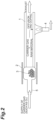
- Fig. 2 is a view for describing the first drying step S1, the second drying step S2, and the thermal diffusion step S3.
- a glass pipe 1 is manufactured.
- the preferable glass pipe 1 contains chlorine of 50 wt ppm to 2000 wt ppm and fluorine of 2000 wt ppm or more, and has a concentration of the other impurities of a lower detection limit (about 1 wt ppm) or less.
- a preferable outer diameter of the glass pipe 1 is 20 to 35 mm and a preferable inner diameter thereof is 10 to 20 mm.
- the glass pipe 1 contains 100 wt ppm of chlorine and 2,000 wt ppm or 6,000 wt ppm of fluorine.
- the outer diameter of the glass pipe 1 is 26 mm, and the inner diameter thereof is 15 mm.
- a handling glass pipe 5 is connected to one end of the above glass pipe 1, and a part of the handling glass pipe 5 is used as a raw material reservoir.
- alkali metal salt raw materials 3 are placed in the raw material reservoir. Kinds and masses of the raw materials placed in the raw material reservoir differ for each sample.
- a part of the glass pipe 1 may be used as the raw material reservoir.
- the first drying step S1 a state where the outside of the raw material reservoir is heated to a predetermined temperature by an external heat source (electric furnace) 2 while introducing 3 SLM (3 L/min in terms of the standard state) of dry nitrogen (having a dew point of -76°C or lower) serving as a carrier gas into the raw material reservoir is maintained for a predetermined time.
- 3 SLM 3 L/min in terms of the standard state
- dry nitrogen having a dew point of -76°C or lower
- the alkali metal salt raw materials are dried at a temperature equal to or higher than melting point temperatures of the alkali metal salt raw materials 3.
- the temperature in the second drying step S2 differs for each of the samples of the present embodiment and the comparative examples.
- the temperature of the raw material reservoir is adjusted to 800°C, and then, 1 SLM of dry oxygen serving as a carrier gas is introduced into the raw material reservoir and the glass pipe 1.
- the glass pipe 1 is heated by the external heat source (oxyhydrogen burner) 4 such that the outer surface has a temperature of 1500°C or higher, for example, 2000°C.
- the oxyhydrogen burner is moved at a constant speed, for example, at a speed of 30 mm/min. As such burner movement is performed 10 times or more in total, 15 times in one example, alkali metal elements diffuse to an inner surface of the glass pipe 1.
- a diameter reduction of the glass pipe 1 is performed such that an inner diameter of the glass pipe 1 is 6 mm or smaller, in one example, about 4 mm.
- etching step S5 SF 6 and Cl 2 are supplied from a gas supply unit to the inside of the glass pipe 1 while heating the glass pipe 1 by the oxyhydrogen burner 4 to a temperature of 1500°C or higher, in one example, 2000°C.
- vapor phase etching of the inner surface of the glass pipe 1 is performed until the inner diameter of the glass pipe 1 is about 5 mm in the etching step S5.
- the glass pipe 1 to which an alkali metal element group has been doped is heated so as to obtain a temperature of 1500°C or higher with the oxyhydrogen burner 4, whereby collapsing of the glass pipe 1 is performed.
- the collapsing is performed while evacuating air such that an internal pressure of the glass pipe 1 becomes about 100 kPa in an absolute pressure.
- a glass rod (alkali metal element-doped glass rod) having an outer diameter of about 25 mm is obtained.
- the outside of the glass rod is sufficiently grinded until OH groups disappear (specifically, until the outer diameter reaches about 70% or less of that after collapsing), whereby a first core portion 111 (constituting a part of the core rod 110 illustrated in Fig. 3 ) is obtained.
- a second core portion 112 (constituting a part of the core rod 110 illustrated in Fig. 3 ) having a diameter about three times a diameter of the first core portion is added to the outside of the first core portion.
- the second core portion 112 is comprised of silica-based glass doped with Cl of an average of 2,000 wt ppm or more, in one example, 6000 wt ppm, and the other impurities of 1 wt ppm or less.
- the first core portion 111 and the second core portion 112 together constitute the core rod 110 (constituting a central portion of an optical fiber preform 100 illustrated in Fig. 3 ).
- a silica-based glass doped with a fluorine element to form a first cladding portion 121 (constituting a part of a cladding portion 120 illustrated in Fig. 3 ) is synthesized on the outside of the core rod 110 (on an outer periphery of the second core portion 112).
- a relative refractive index difference of the first cladding portion 121 relative to the second core portion 112 is about -0.33% when a refractive index of the first cladding portion 121 is the smallest.
- a silica-based glass doped with fluorine having a relative refractive index difference of about -0.23% relative to the second core portion 112 is synthesized on the outside of the first cladding portion 121 as a second cladding portion 122.
- the optical fiber preform 100 illustrated in Fig. 3 is obtained. By drawing this optical fiber preform 100, an optical fiber 500 of each sample according to the present embodiment and optical fibers according to the comparative examples are obtained.
- a cross-sectional structure of the optical fiber 500 is similar to a cross-sectional structure of the optical fiber preform 100 illustrated in Fig. 3 . That is, the optical fiber 500 has a core corresponding to the core rod 110 and a cladding corresponding to the cladding portion 120. Further, in the example of Fig. 3 , the core of the optical fiber 500 has a double core structure constituted by two regions corresponding to the first core portion 111 and the second core portion 112, respectively. On the other hand, the cladding of the optical fiber 500 has a double cladding structure constituted by two regions corresponding to the first cladding portion 121 and the second cladding portion 122, respectively.
- one end of the optical fiber preform 100 having the structure as described above is drawn by a drawing apparatus 300 illustrated in Fig. 3 to obtain the optical fiber 500.
- the drawing apparatus 300 illustrated in Fig. 3 at least includes: a heater 301 configured to heat one end of the set optical fiber preform 100 and a winding drum 302 configured to wind up the heated one end of the optical fiber preform 100 while applying a predetermined tension.
- the winding drum 302 rotates in a direction indicated by an arrow R in Fig. 3 .
- an outer diameter of the optical fiber 500 is adjusted by adjusting the rotation speed of the winding drum 302.
- the tension (drawing tension) applied to the heated one end of the optical fiber preform 100 is adjusted by adjusting a heating temperature by the heater 301.
- optical fibers of Sample 1 and Comparative Example 1 were obtained by drawing an optical fiber preform manufactured by the above-described optical fiber preform manufacturing method using KBr (melting point 730°C) and CsBr (melting point 636°C) as alkali metal salt raw materials.
- both the raw materials were dried for 30 minutes at 550°C lower than the melting points of both the raw materials.
- both the raw materials were dried at 770°C higher than the melting points of both the raw materials.
- a vapor pressure of KBr was 93.3257 Pa (0.7 mmHg)
- a vapor pressure of CsBr was 239.98 Pa (1.8 mmHg).
- a K concentration was 1030 ppm
- a Cs concentration was 2520 ppm.
- An X concentration means a value obtained by averaging a local concentration of an element X in a spatial region where the local concentration of the element X is 50 ppm or more.
- a transmission loss of the optical fiber finally obtained as Sample 1 in a wavelength band of 1.38 ⁇ m was 1 dB/km or less.
- the first drying step was performed under the same conditions as those of Sample 1 in the preform manufacturing to obtain Comparative Example 1.
- both the raw materials were dried at 800°C higher than the melting points of both the raw materials.
- a vapor pressure of KBr was 159.987 Pa (1.2 mmHg)
- a vapor pressure of CsBr was 413.299 Pa (3.1 mmHg).
- a K concentration was 990 ppm
- a Cs concentration was 730 ppm.
- a transmission loss of the optical fiber finally obtained as Comparative Example 1 in a wavelength band of 1.38 ⁇ m was 1 dB/km or less.
- optical fibers of Sample 2 and Comparative Example 2 were obtained by drawing an optical fiber preform manufactured by the above-described optical fiber preform manufacturing method using KBr (melting point 730°C) and CsI (melting point 621°C) as alkali metal salt raw materials.
- both the raw materials were dried for 30 minutes at 550°C lower than the melting points of both the raw materials.
- both the raw materials were dried at 730°C higher than the melting points of both the raw materials.
- a vapor pressure of KBr was 39.9967 Pa (0.3 mmHg)
- a vapor pressure of CsI was 133.322 Pa (1 mmHg).
- Tg In the obtained alkali metal element-doped glass rod, a K concentration was 1210 ppm, and a Cs concentration was 1940 ppm.
- An OH loss increase of the optical fiber finally obtained as Sample 2 in a wavelength band of 1.38 ⁇ m was 1 dB/km or less.
- the first drying step was performed under the same conditions as those of Sample 2.
- both the raw materials were dried at 800°C higher than the melting points of both the raw materials.
- a vapor pressure of KBr was 159.987 Pa (1.2 mmHg)
- a vapor pressure of CsI was 613.283 Pa (4.6 mmHg).
- a K concentration was 1480 ppm
- a Cs concentration was 210 ppm.
- a transmission loss of the optical fiber finally obtained as Comparative Example 2 in a wavelength band of 1.38 ⁇ m was 1 dB/km or less.
- Patent Document 1 suggests a fact that, if the raw material is dried at a temperature at which the raw material is melted beyond a melting point temperature of the raw material as a condition of a second drying step in the case of using one kind of an alkali metal salt raw material, it is also possible to remove moisture inside the raw material, and an OH loss of 1.0 dB/km or less can be realized.
- melting points of the respective raw materials are different, and thus, it is necessary to perform the second drying step S2 at a temperature higher than the melting points of all the raw materials.
- a condition that the vapor pressures of the respective raw materials are 266.645 Pa (2 mmHg) or less is preferable.
- a preferable temperature range to implement the second drying step varies depending on a combination of raw materials, 730°C to 780°C is preferable when using KBr and CsBr, and 730°C to 810°C is preferable when using KBr and RbBr.
- a difference between melting points of raw materials to be used is preferably 100°C or lower, and according to the invention is 50°C or lower.
- optical fibers of Samples 3A, 3B, and 3C were obtained by drawing an optical fiber preform manufactured by the above-described optical fiber preform manufacturing method using KBr (melting point 734°C) and RbBr (melting point 693°C) as alkali metal salt raw materials.
- Fig. 4 is a table summarizing a mass of each raw material placed in a raw material reservoir in each of Samples 3A, 3B, and 3C.
- a mass of RbBr placed in the raw material reservoir was set to 5 g in all of Samples 3A, 3B, and 3C.
- a mass of KBr placed in the raw material reservoir was set to 3 g in Sample 3A, 5 g in Sample 3B, and 7 g in Sample 3C.
- 3 SLM 3 L/min in terms of the standard state
- dry nitrogen having a dew point of -76°C or lower
- a carrier gas serving as a carrier gas
- a state where the outside of the raw material reservoir is heated to 500°C by the external heat source (electric furnace) 2 while introducing the dry nitrogen is maintained for 30 minutes so as to perform drying of the alkali metal salt raw materials 3 placed in the raw material reservoir.
- the alkali metal salt raw materials 3 placed in the raw material reservoir were dried at 770°C higher than the melting point temperatures of both the raw materials.
- a concentration of each alkali metal element was measured by an electron probe micro analyzer (EPMA) for an alkali metal element-doped glass rod having an outer diameter of about 16 mm obtained in the process of this preform manufacturing.
- EPMA electron probe micro analyzer
- a transmission loss at a wavelength of 1550 nm of the optical fiber finally obtained as each of Samples 3A, 3B, and 3C was measured.
- Fig. 5 is a table summarizing a peak concentration of each alkali metal element measured by EPMA in each of Samples 3A, 3B, and 3C. That is, a peak concentration of K in Sample 3A was 620 wt ppm and a peak concentration of Rb thereof was 2890 wt ppm in Fig. 5 . A peak concentration of K in Sample 3B was 1050 wt ppm and a peak concentration of Rb thereof was 3000 wt ppm. A peak concentration of K in Sample 3C was 1370 wt ppm and a peak concentration of Rb thereof was 2970 wt ppm.
- a mass of RbBr inputted to the raw material reservoir was 5 g in all of Samples 3A, 3B, and 3C, and an Rb concentration was about 3000 wt ppm at the maximum.
- an Rb concentration was about 3000 wt ppm at the maximum.
- Fig. 6 is a table summarizing a transmission loss at a wavelength of 1550 nm measured in each of Samples 3A, 3B, and 3C.
- the transmission loss of Sample 3A was 0.155 dB/km
- the transmission loss of Sample 3B was 0.153 dB/km
- the transmission loss of Sample 3C was 0.152 dB/km.
- the Rayleigh scattering loss is lower as an alkali metal concentration is higher.
- Samples 4A, 4B, and 4C were obtained by drawing an optical fiber preform manufactured by the above-described optical fiber preform manufacturing method using KBr (melting point 734°C) and RbI (melting point 647°C) as alkali metal salt raw materials.
- Fig. 7 is a table summarizing a mass of each of the raw materials placed in a raw material reservoir in each of Samples 4A, 4B, and 4C.
- a mass of RbI placed in the raw material reservoir was set to 5 g in all of Samples 4A, 4B, and 4C.
- a mass of KBr placed in the raw material reservoir was set to 3 g in Sample 4A, 5 g in Sample 4B, and 7 g in Sample 4C.
- the first drying step S 1 and the second drying step S2 were performed under the same conditions as those in the preform manufacturing to obtain Samples 3A, 3B, and 3C.
- a concentration of each alkali metal element in an alkali metal element-doped glass rod having an outer diameter of about 16 mm obtained in the process of the preform manufacturing was measured by EPMA, and a transmission loss at a wavelength of 1550 nm of the finally obtained optical fiber was measured.
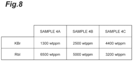
- Fig. 8 is a table summarizing a peak concentration of each alkali metal element measured by EPMA in each of Samples 4A, 4B, and 4C. That is, a peak concentration of K in Sample 4A was 1300 wt ppm and a peak concentration of Rb thereof was 6500 wt ppm in Fig. 8 . A peak concentration of K in Sample 4B was 2500 wt ppm and a peak concentration of Rb thereof was 5000 wt ppm. A peak concentration of K in Sample 4C was 4400 wt ppm and a peak concentration of Rb thereof was 3200 wt ppm. As can be seen from Fig.
- Fig. 9 is a table summarizing a transmission loss of an optical fiber at a wavelength of 1550 nm measured in each of Samples 4A, 4B, and 4C of the present embodiment.
- the transmission loss of Sample 4A was 0.153 dB/km
- the transmission loss of Sample 4B was 0.151 dB/km
- the transmission loss of Sample 4C was 0.151 dB/km.
- the Rayleigh scattering loss is lower as the K concentration is higher.
- Samples 3A, 3B and 3C are made according the invention.
- 1 glass pipe; 2.... external heat source (electric furnace); 3...alkali metal salt raw material; 4 ... external heat source (oxyhydrogen burner); 5 ... handling glass pipe; 100 ... optical fiber preform; 110 ... core rod; 111 ... first core portion; 112 ... second core portion; 120 ... cladding portion; 121 ... first cladding portion; and 122 ... second cladding portion.
Landscapes
- Chemical & Material Sciences (AREA)
- Engineering & Computer Science (AREA)
- Physics & Mathematics (AREA)
- Materials Engineering (AREA)
- Life Sciences & Earth Sciences (AREA)
- General Life Sciences & Earth Sciences (AREA)
- Geochemistry & Mineralogy (AREA)
- Manufacturing & Machinery (AREA)
- General Chemical & Material Sciences (AREA)
- Organic Chemistry (AREA)
- Chemical Kinetics & Catalysis (AREA)
- General Physics & Mathematics (AREA)
- Optics & Photonics (AREA)
- Thermal Sciences (AREA)
- Glass Compositions (AREA)
- Manufacture, Treatment Of Glass Fibers (AREA)
Claims (6)
- Herstellungsverfahren für eine Glasfaservorform, umfassend:einen ersten Trocknungsschritt zum Trocknen zweier oder mehrerer Arten von Rohstoffen aus Alkalimetallsalz, die voneinander verschiedene Alkalimetallelemente auf einer Temperatur gleich wie, oder niedriger als eine niedrigste Temperatur aus Schmelzpunkttemperaturen der beiden oder mehreren Arten von Rohstoffen aus Alkalimetallsalz enthalten;einen zweiten Trocknungsschritt nach dem ersten Trocknungsschritt, zum Trocknen der beiden oder mehreren Arten von Rohstoffen aus Alkalimetallsalz auf einer Temperatur, die gleich wie, oder höher als eine höchste Temperatur aus den Schmelzpunkttemperaturen der beiden oder mehreren Arten von Rohstoffen aus Alkalimetallsalz ist, und bei der Dampfdrücke aller der beiden oder mehreren Arten von Rohstoffen aus Alkalimetallsalz 266,645 Pa (2 mmHg) oder weniger betragen;einen Wärmediffusionsschritt, nach dem zweiten Trocknungsschritt, zur Wärmediffusion zweier oder mehrerer Arten von Alkalimetallelementoxiden an einer Innenoberfläche eines Glasrohres auf Basis von Siliziumdioxid, wobei der Wärmediffusionsschritt gleichzeitig das Erwärmen der beiden oder mehreren Arten von Rohstoffen aus Alkalimetallsalz umfasst, um Dampf der beiden oder mehreren Arten von Rohstoffen aus Alkalimetallsalz zu erzeugen, und den Dampf und ein Trägergas von einer Endseite des Glasrohres zu einer Innenseite des Glasrohres zuzuführen, während das Glasrohr mit einer Wärmequelle erwärmt wird, um eine Oxidationsreaktion von zwei oder mehreren Arten von Alkalimetallelementen zu bewirken, die in dem Dampf enthalten sind, wobei sich die Wärmequelle relativ in einer Längsrichtung des Glasrohres bewegt;einen Kernstab-Fertigungsschritt nach dem Wärmediffusionsschritt durch Zusammenbrechen des Glasrohres zur Fertigung des Kernstabes; undeinen Schritt zum Hinzufügen eines Umhüllungsabschnitts nach dem Kernstab-Fertigungsschritt, durch Hinzufügen eines Umhüllungsabschnitts an einem Außenumfang des Kernstabes,wobei ein Unterschied unter den Schmelzpunkttemperaturen der beiden oder mehreren Arten von Rohstoffen aus Alkalimetallsalz 50° C oder weniger beträgt.
- Herstellungsverfahren für eine Glasfaservorform nach Anspruch 1, wobei
alle von den beiden oder mehreren Arten von Rohstoffen aus Alkalimetallsalz Brom-Verbindungen sind. - Herstellungsverfahren für eine Glasfaservorform nach Anspruch 1, wobei
alle von den beiden oder mehreren Arten von Rohstoffen aus Alkalimetallsalz JodVerbindungen sind. - Herstellungsverfahren für eine Glasfaservorform nach Anspruch 1, wobei
alle von den beiden oder mehreren Arten von Rohstoffen aus Alkalimetallsalz Chlor-Verbindungen sind. - Herstellungsverfahren für eine Glasfaservorform nach einem der Ansprüche 1 bis 4, wobeidas Glasrohr Chlor und Fluor enthält,eine durchschnittliche Konzentration von jedem von Chlor und Fluor, die in dem Glasrohr enthalten sind, 10 Gew.-ppm oder mehr beträgt, undeine Konzentration von Verunreinigungen, ausgenommen Chlor und Fluor unter den Verunreinigungen, die in dem Glasrohr enthalten sind, 10 Gew.-ppm oder weniger beträgt.
- Herstellungsverfahren für eine Glasfaservorform nach einem der Ansprüche 1 bis 5, wobei eine maximale Spitzenkonzentration unter den Konzentrationen der beiden oder mehreren Arten von Alkalimetallelementen, die in dem Dampf enthalten sind, der in dem Wärmediffusionsschritt erzeugt wird, 200 Gew.-ppm oder mehr beträgt.
Applications Claiming Priority (2)
| Application Number | Priority Date | Filing Date | Title |
|---|---|---|---|
| JP2016240482 | 2016-12-12 | ||
| PCT/JP2017/041986 WO2018110234A1 (ja) | 2016-12-12 | 2017-11-22 | 光ファイバ母材製造方法、光ファイバ母材、および光ファイバ |
Publications (3)
| Publication Number | Publication Date |
|---|---|
| EP3553035A1 EP3553035A1 (de) | 2019-10-16 |
| EP3553035A4 EP3553035A4 (de) | 2019-12-11 |
| EP3553035B1 true EP3553035B1 (de) | 2023-07-19 |
Family
ID=62558248
Family Applications (1)
| Application Number | Title | Priority Date | Filing Date |
|---|---|---|---|
| EP17880292.2A Active EP3553035B1 (de) | 2016-12-12 | 2017-11-22 | Herstellungsverfahren für glasfasergrundmaterial |
Country Status (6)
| Country | Link |
|---|---|
| US (1) | US20190292089A1 (de) |
| EP (1) | EP3553035B1 (de) |
| JP (1) | JP6954309B2 (de) |
| CN (1) | CN110049955A (de) |
| DK (1) | DK3553035T3 (de) |
| WO (1) | WO2018110234A1 (de) |
Families Citing this family (3)
| Publication number | Priority date | Publication date | Assignee | Title |
|---|---|---|---|---|
| CN110395900A (zh) * | 2019-08-02 | 2019-11-01 | 长飞光纤光缆股份有限公司 | 一种管外法制备低衰耗光纤预制棒的沉积装置及方法 |
| JPWO2023238619A1 (de) * | 2022-06-10 | 2023-12-14 | ||
| JPWO2024252898A1 (de) * | 2023-06-06 | 2024-12-12 |
Citations (1)
| Publication number | Priority date | Publication date | Assignee | Title |
|---|---|---|---|---|
| WO2004020357A2 (en) * | 2002-08-28 | 2004-03-11 | Corning Incorporated | A low loss optical glass-fiber and method for making the optical fiber precursor |
Family Cites Families (8)
| Publication number | Priority date | Publication date | Assignee | Title |
|---|---|---|---|---|
| CN100545113C (zh) * | 2003-08-29 | 2009-09-30 | 康宁股份有限公司 | 含碱金属氧化物的光纤及制造该光纤的方法和设备 |
| US20060130530A1 (en) | 2004-12-21 | 2006-06-22 | Anderson James G | Method of doping silica glass with an alkali metal, and optical fiber precursor formed therefrom |
| JP5974455B2 (ja) * | 2011-11-21 | 2016-08-23 | 住友電気工業株式会社 | 光ファイバ母材、光ファイバ製造方法および光ファイバ |
| JP5903896B2 (ja) * | 2012-01-11 | 2016-04-13 | 住友電気工業株式会社 | 光ファイバ母材製造方法 |
| JP6048418B2 (ja) * | 2012-02-09 | 2016-12-21 | 住友電気工業株式会社 | 光ファイバ母材製造方法 |
| JP6106453B2 (ja) * | 2013-02-21 | 2017-03-29 | 株式会社フジクラ | ガラス母材の製造装置 |
| JP5995923B2 (ja) * | 2014-08-06 | 2016-09-21 | 古河電気工業株式会社 | 光ファイバ母材および光ファイバの製造方法 |
| JP6551109B2 (ja) * | 2014-11-20 | 2019-07-31 | 住友電気工業株式会社 | 光ファイバ |
-
2017
- 2017-11-22 EP EP17880292.2A patent/EP3553035B1/de active Active
- 2017-11-22 DK DK17880292.2T patent/DK3553035T3/da active
- 2017-11-22 CN CN201780076212.XA patent/CN110049955A/zh active Pending
- 2017-11-22 JP JP2018556528A patent/JP6954309B2/ja active Active
- 2017-11-22 WO PCT/JP2017/041986 patent/WO2018110234A1/ja not_active Ceased
-
2019
- 2019-06-11 US US16/436,965 patent/US20190292089A1/en not_active Abandoned
Patent Citations (1)
| Publication number | Priority date | Publication date | Assignee | Title |
|---|---|---|---|---|
| WO2004020357A2 (en) * | 2002-08-28 | 2004-03-11 | Corning Incorporated | A low loss optical glass-fiber and method for making the optical fiber precursor |
Also Published As
| Publication number | Publication date |
|---|---|
| EP3553035A1 (de) | 2019-10-16 |
| EP3553035A4 (de) | 2019-12-11 |
| WO2018110234A1 (ja) | 2018-06-21 |
| JPWO2018110234A1 (ja) | 2019-10-24 |
| CN110049955A (zh) | 2019-07-23 |
| US20190292089A1 (en) | 2019-09-26 |
| DK3553035T3 (da) | 2023-08-21 |
| JP6954309B2 (ja) | 2021-10-27 |
Similar Documents
| Publication | Publication Date | Title |
|---|---|---|
| JP5916966B2 (ja) | 光ファイバ母材の製造方法および光ファイバの製造方法 | |
| EP2479150B1 (de) | Optische Faservorform, optische Faser und Verfahren zur Herstellung einer optischen Faservorform | |
| CN104981440B (zh) | 光纤母材以及光纤母材的制造方法 | |
| EP3040749B1 (de) | Optische faser mit alkalimetalldotiertem quarzglaskern | |
| EP2692705B1 (de) | Verfahren zur herstellung eines glasfaserbasismaterials | |
| DK2813477T3 (en) | METHOD FOR MANUFACTURING OPTICAL FIBER PREFORM, OPTICAL FIBER PREFORM, AND OPTICAL FIBER | |
| EP3435126B1 (de) | Optische faser | |
| JP2005537210A (ja) | 低損失光ファイバおよびその製造方法 | |
| CN106082630B (zh) | 光纤预制件 | |
| US20190292089A1 (en) | Optical fiber base material manufacturing method, optical fiber base material, and optical fiber | |
| JP2024544516A (ja) | 低損失光ファイバを製造するための方法 | |
| EP3178793A1 (de) | Lichtleitfasergrundmaterial und verfahren zur herstellung einer lichtleitfaser | |
| JP6795983B2 (ja) | 光ファイバ用母材の製造方法、及び、これを用いた光ファイバの製造方法 | |
| JP7794128B2 (ja) | 光ファイバ母材の製造方法及び光ファイバ母材 | |
| CA2948666C (en) | Polarization controlling optical fiber preform and preform fabrication methods | |
| US20230167002A1 (en) | Optical fibers and method of making the same | |
| JP2024106682A (ja) | 光ファイバ母材の製造方法および光ファイバの製造方法 | |
| DK202530761A1 (en) | Reservoir, method for producing optical fiber, and device for producing optical fiber |
Legal Events
| Date | Code | Title | Description |
|---|---|---|---|
| STAA | Information on the status of an ep patent application or granted ep patent |
Free format text: STATUS: THE INTERNATIONAL PUBLICATION HAS BEEN MADE |
|
| PUAI | Public reference made under article 153(3) epc to a published international application that has entered the european phase |
Free format text: ORIGINAL CODE: 0009012 |
|
| STAA | Information on the status of an ep patent application or granted ep patent |
Free format text: STATUS: REQUEST FOR EXAMINATION WAS MADE |
|
| 17P | Request for examination filed |
Effective date: 20190611 |
|
| AK | Designated contracting states |
Kind code of ref document: A1 Designated state(s): AL AT BE BG CH CY CZ DE DK EE ES FI FR GB GR HR HU IE IS IT LI LT LU LV MC MK MT NL NO PL PT RO RS SE SI SK SM TR |
|
| AX | Request for extension of the european patent |
Extension state: BA ME |
|
| A4 | Supplementary search report drawn up and despatched |
Effective date: 20191113 |
|
| RIC1 | Information provided on ipc code assigned before grant |
Ipc: C03B 37/018 20060101AFI20191107BHEP Ipc: C03B 37/014 20060101ALI20191107BHEP Ipc: G02B 6/02 20060101ALI20191107BHEP |
|
| DAV | Request for validation of the european patent (deleted) | ||
| DAX | Request for extension of the european patent (deleted) | ||
| STAA | Information on the status of an ep patent application or granted ep patent |
Free format text: STATUS: EXAMINATION IS IN PROGRESS |
|
| 17Q | First examination report despatched |
Effective date: 20201106 |
|
| GRAP | Despatch of communication of intention to grant a patent |
Free format text: ORIGINAL CODE: EPIDOSNIGR1 |
|
| STAA | Information on the status of an ep patent application or granted ep patent |
Free format text: STATUS: GRANT OF PATENT IS INTENDED |
|
| INTG | Intention to grant announced |
Effective date: 20230213 |
|
| GRAS | Grant fee paid |
Free format text: ORIGINAL CODE: EPIDOSNIGR3 |
|
| GRAA | (expected) grant |
Free format text: ORIGINAL CODE: 0009210 |
|
| STAA | Information on the status of an ep patent application or granted ep patent |
Free format text: STATUS: THE PATENT HAS BEEN GRANTED |
|
| P01 | Opt-out of the competence of the unified patent court (upc) registered |
Effective date: 20230515 |
|
| AK | Designated contracting states |
Kind code of ref document: B1 Designated state(s): AL AT BE BG CH CY CZ DE DK EE ES FI FR GB GR HR HU IE IS IT LI LT LU LV MC MK MT NL NO PL PT RO RS SE SI SK SM TR |
|
| REG | Reference to a national code |
Ref country code: GB Ref legal event code: FG4D |
|
| REG | Reference to a national code |
Ref country code: CH Ref legal event code: EP |
|
| REG | Reference to a national code |
Ref country code: DE Ref legal event code: R096 Ref document number: 602017071623 Country of ref document: DE |
|
| REG | Reference to a national code |
Ref country code: IE Ref legal event code: FG4D |
|
| REG | Reference to a national code |
Ref country code: DK Ref legal event code: T3 Effective date: 20230814 |
|
| REG | Reference to a national code |
Ref country code: LT Ref legal event code: MG9D |
|
| REG | Reference to a national code |
Ref country code: NL Ref legal event code: MP Effective date: 20230719 |
|
| REG | Reference to a national code |
Ref country code: AT Ref legal event code: MK05 Ref document number: 1589321 Country of ref document: AT Kind code of ref document: T Effective date: 20230719 |
|
| PG25 | Lapsed in a contracting state [announced via postgrant information from national office to epo] |
Ref country code: NL Free format text: LAPSE BECAUSE OF FAILURE TO SUBMIT A TRANSLATION OF THE DESCRIPTION OR TO PAY THE FEE WITHIN THE PRESCRIBED TIME-LIMIT Effective date: 20230719 |
|
| PG25 | Lapsed in a contracting state [announced via postgrant information from national office to epo] |
Ref country code: GR Free format text: LAPSE BECAUSE OF FAILURE TO SUBMIT A TRANSLATION OF THE DESCRIPTION OR TO PAY THE FEE WITHIN THE PRESCRIBED TIME-LIMIT Effective date: 20231020 |
|
| PG25 | Lapsed in a contracting state [announced via postgrant information from national office to epo] |
Ref country code: IS Free format text: LAPSE BECAUSE OF FAILURE TO SUBMIT A TRANSLATION OF THE DESCRIPTION OR TO PAY THE FEE WITHIN THE PRESCRIBED TIME-LIMIT Effective date: 20231119 |
|
| PG25 | Lapsed in a contracting state [announced via postgrant information from national office to epo] |
Ref country code: SE Free format text: LAPSE BECAUSE OF FAILURE TO SUBMIT A TRANSLATION OF THE DESCRIPTION OR TO PAY THE FEE WITHIN THE PRESCRIBED TIME-LIMIT Effective date: 20230719 Ref country code: RS Free format text: LAPSE BECAUSE OF FAILURE TO SUBMIT A TRANSLATION OF THE DESCRIPTION OR TO PAY THE FEE WITHIN THE PRESCRIBED TIME-LIMIT Effective date: 20230719 Ref country code: PT Free format text: LAPSE BECAUSE OF FAILURE TO SUBMIT A TRANSLATION OF THE DESCRIPTION OR TO PAY THE FEE WITHIN THE PRESCRIBED TIME-LIMIT Effective date: 20231120 Ref country code: NO Free format text: LAPSE BECAUSE OF FAILURE TO SUBMIT A TRANSLATION OF THE DESCRIPTION OR TO PAY THE FEE WITHIN THE PRESCRIBED TIME-LIMIT Effective date: 20231019 Ref country code: LV Free format text: LAPSE BECAUSE OF FAILURE TO SUBMIT A TRANSLATION OF THE DESCRIPTION OR TO PAY THE FEE WITHIN THE PRESCRIBED TIME-LIMIT Effective date: 20230719 Ref country code: LT Free format text: LAPSE BECAUSE OF FAILURE TO SUBMIT A TRANSLATION OF THE DESCRIPTION OR TO PAY THE FEE WITHIN THE PRESCRIBED TIME-LIMIT Effective date: 20230719 Ref country code: IS Free format text: LAPSE BECAUSE OF FAILURE TO SUBMIT A TRANSLATION OF THE DESCRIPTION OR TO PAY THE FEE WITHIN THE PRESCRIBED TIME-LIMIT Effective date: 20231119 Ref country code: HR Free format text: LAPSE BECAUSE OF FAILURE TO SUBMIT A TRANSLATION OF THE DESCRIPTION OR TO PAY THE FEE WITHIN THE PRESCRIBED TIME-LIMIT Effective date: 20230719 Ref country code: GR Free format text: LAPSE BECAUSE OF FAILURE TO SUBMIT A TRANSLATION OF THE DESCRIPTION OR TO PAY THE FEE WITHIN THE PRESCRIBED TIME-LIMIT Effective date: 20231020 Ref country code: FI Free format text: LAPSE BECAUSE OF FAILURE TO SUBMIT A TRANSLATION OF THE DESCRIPTION OR TO PAY THE FEE WITHIN THE PRESCRIBED TIME-LIMIT Effective date: 20230719 Ref country code: AT Free format text: LAPSE BECAUSE OF FAILURE TO SUBMIT A TRANSLATION OF THE DESCRIPTION OR TO PAY THE FEE WITHIN THE PRESCRIBED TIME-LIMIT Effective date: 20230719 |
|
| PG25 | Lapsed in a contracting state [announced via postgrant information from national office to epo] |
Ref country code: PL Free format text: LAPSE BECAUSE OF FAILURE TO SUBMIT A TRANSLATION OF THE DESCRIPTION OR TO PAY THE FEE WITHIN THE PRESCRIBED TIME-LIMIT Effective date: 20230719 |
|
| REG | Reference to a national code |
Ref country code: DE Ref legal event code: R097 Ref document number: 602017071623 Country of ref document: DE |
|
| PG25 | Lapsed in a contracting state [announced via postgrant information from national office to epo] |
Ref country code: ES Free format text: LAPSE BECAUSE OF FAILURE TO SUBMIT A TRANSLATION OF THE DESCRIPTION OR TO PAY THE FEE WITHIN THE PRESCRIBED TIME-LIMIT Effective date: 20230719 |
|
| PG25 | Lapsed in a contracting state [announced via postgrant information from national office to epo] |
Ref country code: SM Free format text: LAPSE BECAUSE OF FAILURE TO SUBMIT A TRANSLATION OF THE DESCRIPTION OR TO PAY THE FEE WITHIN THE PRESCRIBED TIME-LIMIT Effective date: 20230719 Ref country code: RO Free format text: LAPSE BECAUSE OF FAILURE TO SUBMIT A TRANSLATION OF THE DESCRIPTION OR TO PAY THE FEE WITHIN THE PRESCRIBED TIME-LIMIT Effective date: 20230719 Ref country code: ES Free format text: LAPSE BECAUSE OF FAILURE TO SUBMIT A TRANSLATION OF THE DESCRIPTION OR TO PAY THE FEE WITHIN THE PRESCRIBED TIME-LIMIT Effective date: 20230719 Ref country code: EE Free format text: LAPSE BECAUSE OF FAILURE TO SUBMIT A TRANSLATION OF THE DESCRIPTION OR TO PAY THE FEE WITHIN THE PRESCRIBED TIME-LIMIT Effective date: 20230719 Ref country code: CZ Free format text: LAPSE BECAUSE OF FAILURE TO SUBMIT A TRANSLATION OF THE DESCRIPTION OR TO PAY THE FEE WITHIN THE PRESCRIBED TIME-LIMIT Effective date: 20230719 Ref country code: SK Free format text: LAPSE BECAUSE OF FAILURE TO SUBMIT A TRANSLATION OF THE DESCRIPTION OR TO PAY THE FEE WITHIN THE PRESCRIBED TIME-LIMIT Effective date: 20230719 |
|
| PLBE | No opposition filed within time limit |
Free format text: ORIGINAL CODE: 0009261 |
|
| STAA | Information on the status of an ep patent application or granted ep patent |
Free format text: STATUS: NO OPPOSITION FILED WITHIN TIME LIMIT |
|
| PG25 | Lapsed in a contracting state [announced via postgrant information from national office to epo] |
Ref country code: IT Free format text: LAPSE BECAUSE OF FAILURE TO SUBMIT A TRANSLATION OF THE DESCRIPTION OR TO PAY THE FEE WITHIN THE PRESCRIBED TIME-LIMIT Effective date: 20230719 |
|
| REG | Reference to a national code |
Ref country code: DE Ref legal event code: R119 Ref document number: 602017071623 Country of ref document: DE |
|
| 26N | No opposition filed |
Effective date: 20240422 |
|
| REG | Reference to a national code |
Ref country code: CH Ref legal event code: PL |
|
| PG25 | Lapsed in a contracting state [announced via postgrant information from national office to epo] |
Ref country code: MC Free format text: LAPSE BECAUSE OF FAILURE TO SUBMIT A TRANSLATION OF THE DESCRIPTION OR TO PAY THE FEE WITHIN THE PRESCRIBED TIME-LIMIT Effective date: 20230719 |
|
| PG25 | Lapsed in a contracting state [announced via postgrant information from national office to epo] |
Ref country code: LU Free format text: LAPSE BECAUSE OF NON-PAYMENT OF DUE FEES Effective date: 20231122 |
|
| PG25 | Lapsed in a contracting state [announced via postgrant information from national office to epo] |
Ref country code: CH Free format text: LAPSE BECAUSE OF NON-PAYMENT OF DUE FEES Effective date: 20231130 |
|
| PG25 | Lapsed in a contracting state [announced via postgrant information from national office to epo] |
Ref country code: MC Free format text: LAPSE BECAUSE OF FAILURE TO SUBMIT A TRANSLATION OF THE DESCRIPTION OR TO PAY THE FEE WITHIN THE PRESCRIBED TIME-LIMIT Effective date: 20230719 Ref country code: LU Free format text: LAPSE BECAUSE OF NON-PAYMENT OF DUE FEES Effective date: 20231122 Ref country code: CH Free format text: LAPSE BECAUSE OF NON-PAYMENT OF DUE FEES Effective date: 20231130 Ref country code: SI Free format text: LAPSE BECAUSE OF FAILURE TO SUBMIT A TRANSLATION OF THE DESCRIPTION OR TO PAY THE FEE WITHIN THE PRESCRIBED TIME-LIMIT Effective date: 20230719 |
|
| REG | Reference to a national code |
Ref country code: BE Ref legal event code: MM Effective date: 20231130 |
|
| REG | Reference to a national code |
Ref country code: IE Ref legal event code: MM4A |
|
| PG25 | Lapsed in a contracting state [announced via postgrant information from national office to epo] |
Ref country code: IE Free format text: LAPSE BECAUSE OF NON-PAYMENT OF DUE FEES Effective date: 20231122 Ref country code: DE Free format text: LAPSE BECAUSE OF NON-PAYMENT OF DUE FEES Effective date: 20240601 |
|
| PG25 | Lapsed in a contracting state [announced via postgrant information from national office to epo] |
Ref country code: BE Free format text: LAPSE BECAUSE OF NON-PAYMENT OF DUE FEES Effective date: 20231130 |
|
| PG25 | Lapsed in a contracting state [announced via postgrant information from national office to epo] |
Ref country code: IE Free format text: LAPSE BECAUSE OF NON-PAYMENT OF DUE FEES Effective date: 20231122 Ref country code: DE Free format text: LAPSE BECAUSE OF NON-PAYMENT OF DUE FEES Effective date: 20240601 Ref country code: BE Free format text: LAPSE BECAUSE OF NON-PAYMENT OF DUE FEES Effective date: 20231130 |
|
| PG25 | Lapsed in a contracting state [announced via postgrant information from national office to epo] |
Ref country code: BG Free format text: LAPSE BECAUSE OF FAILURE TO SUBMIT A TRANSLATION OF THE DESCRIPTION OR TO PAY THE FEE WITHIN THE PRESCRIBED TIME-LIMIT Effective date: 20230719 |
|
| PG25 | Lapsed in a contracting state [announced via postgrant information from national office to epo] |
Ref country code: BG Free format text: LAPSE BECAUSE OF FAILURE TO SUBMIT A TRANSLATION OF THE DESCRIPTION OR TO PAY THE FEE WITHIN THE PRESCRIBED TIME-LIMIT Effective date: 20230719 |
|
| PG25 | Lapsed in a contracting state [announced via postgrant information from national office to epo] |
Ref country code: CY Free format text: LAPSE BECAUSE OF FAILURE TO SUBMIT A TRANSLATION OF THE DESCRIPTION OR TO PAY THE FEE WITHIN THE PRESCRIBED TIME-LIMIT; INVALID AB INITIO Effective date: 20171122 |
|
| PG25 | Lapsed in a contracting state [announced via postgrant information from national office to epo] |
Ref country code: HU Free format text: LAPSE BECAUSE OF FAILURE TO SUBMIT A TRANSLATION OF THE DESCRIPTION OR TO PAY THE FEE WITHIN THE PRESCRIBED TIME-LIMIT; INVALID AB INITIO Effective date: 20171122 |
|
| PGFP | Annual fee paid to national office [announced via postgrant information from national office to epo] |
Ref country code: FR Payment date: 20250930 Year of fee payment: 9 |
|
| PG25 | Lapsed in a contracting state [announced via postgrant information from national office to epo] |
Ref country code: TR Free format text: LAPSE BECAUSE OF FAILURE TO SUBMIT A TRANSLATION OF THE DESCRIPTION OR TO PAY THE FEE WITHIN THE PRESCRIBED TIME-LIMIT Effective date: 20230719 |
|
| PGFP | Annual fee paid to national office [announced via postgrant information from national office to epo] |
Ref country code: GB Payment date: 20251001 Year of fee payment: 9 |
|
| PGFP | Annual fee paid to national office [announced via postgrant information from national office to epo] |
Ref country code: DK Payment date: 20251112 Year of fee payment: 9 |