EP3552998A2 - Device for moving load carriers, adapter for holding load carrier and transport vehicle for picking up and transporting load carriers - Google Patents
Device for moving load carriers, adapter for holding load carrier and transport vehicle for picking up and transporting load carriers Download PDFInfo
- Publication number
- EP3552998A2 EP3552998A2 EP19168741.7A EP19168741A EP3552998A2 EP 3552998 A2 EP3552998 A2 EP 3552998A2 EP 19168741 A EP19168741 A EP 19168741A EP 3552998 A2 EP3552998 A2 EP 3552998A2
- Authority
- EP
- European Patent Office
- Prior art keywords
- carriage
- guide column
- adapter
- trolley
- load
- Prior art date
- Legal status (The legal status is an assumption and is not a legal conclusion. Google has not performed a legal analysis and makes no representation as to the accuracy of the status listed.)
- Pending
Links
- 239000000969 carrier Substances 0.000 title abstract description 75
- 239000002800 charge carrier Substances 0.000 claims abstract description 138
- 238000010168 coupling process Methods 0.000 claims description 35
- 230000008878 coupling Effects 0.000 claims description 34
- 238000005859 coupling reaction Methods 0.000 claims description 34
- 238000012546 transfer Methods 0.000 description 22
- 238000003860 storage Methods 0.000 description 16
- 239000000314 lubricant Substances 0.000 description 8
- 239000007788 liquid Substances 0.000 description 6
- 239000007819 coupling partner Substances 0.000 description 5
- 230000006378 damage Effects 0.000 description 5
- 238000000034 method Methods 0.000 description 5
- 230000008901 benefit Effects 0.000 description 4
- 238000013461 design Methods 0.000 description 4
- 238000005096 rolling process Methods 0.000 description 4
- 239000007787 solid Substances 0.000 description 4
- 230000004888 barrier function Effects 0.000 description 3
- 238000005452 bending Methods 0.000 description 3
- 238000004519 manufacturing process Methods 0.000 description 3
- 238000012545 processing Methods 0.000 description 3
- 230000003716 rejuvenation Effects 0.000 description 3
- 208000027418 Wounds and injury Diseases 0.000 description 2
- 230000000694 effects Effects 0.000 description 2
- 239000012530 fluid Substances 0.000 description 2
- 231100000206 health hazard Toxicity 0.000 description 2
- 230000006698 induction Effects 0.000 description 2
- 208000014674 injury Diseases 0.000 description 2
- 239000000463 material Substances 0.000 description 2
- 230000008569 process Effects 0.000 description 2
- 230000009471 action Effects 0.000 description 1
- 230000006978 adaptation Effects 0.000 description 1
- 238000013459 approach Methods 0.000 description 1
- 230000000903 blocking effect Effects 0.000 description 1
- 239000013590 bulk material Substances 0.000 description 1
- 210000000078 claw Anatomy 0.000 description 1
- 238000004140 cleaning Methods 0.000 description 1
- 238000010276 construction Methods 0.000 description 1
- 239000002826 coolant Substances 0.000 description 1
- 238000005520 cutting process Methods 0.000 description 1
- 230000001419 dependent effect Effects 0.000 description 1
- 238000000151 deposition Methods 0.000 description 1
- 238000007599 discharging Methods 0.000 description 1
- 238000006073 displacement reaction Methods 0.000 description 1
- 238000003754 machining Methods 0.000 description 1
- 230000007246 mechanism Effects 0.000 description 1
- 230000007704 transition Effects 0.000 description 1
Images




Classifications
-
- B—PERFORMING OPERATIONS; TRANSPORTING
- B65—CONVEYING; PACKING; STORING; HANDLING THIN OR FILAMENTARY MATERIAL
- B65G—TRANSPORT OR STORAGE DEVICES, e.g. CONVEYORS FOR LOADING OR TIPPING, SHOP CONVEYOR SYSTEMS OR PNEUMATIC TUBE CONVEYORS
- B65G65/00—Loading or unloading
- B65G65/23—Devices for tilting and emptying of containers
-
- B—PERFORMING OPERATIONS; TRANSPORTING
- B65—CONVEYING; PACKING; STORING; HANDLING THIN OR FILAMENTARY MATERIAL
- B65G—TRANSPORT OR STORAGE DEVICES, e.g. CONVEYORS FOR LOADING OR TIPPING, SHOP CONVEYOR SYSTEMS OR PNEUMATIC TUBE CONVEYORS
- B65G65/00—Loading or unloading
-
- B—PERFORMING OPERATIONS; TRANSPORTING
- B66—HOISTING; LIFTING; HAULING
- B66F—HOISTING, LIFTING, HAULING OR PUSHING, NOT OTHERWISE PROVIDED FOR, e.g. DEVICES WHICH APPLY A LIFTING OR PUSHING FORCE DIRECTLY TO THE SURFACE OF A LOAD
- B66F9/00—Devices for lifting or lowering bulky or heavy goods for loading or unloading purposes
- B66F9/06—Devices for lifting or lowering bulky or heavy goods for loading or unloading purposes movable, with their loads, on wheels or the like, e.g. fork-lift trucks
- B66F9/075—Constructional features or details
- B66F9/08—Masts; Guides; Chains
- B66F9/087—Monomasts
-
- B—PERFORMING OPERATIONS; TRANSPORTING
- B65—CONVEYING; PACKING; STORING; HANDLING THIN OR FILAMENTARY MATERIAL
- B65G—TRANSPORT OR STORAGE DEVICES, e.g. CONVEYORS FOR LOADING OR TIPPING, SHOP CONVEYOR SYSTEMS OR PNEUMATIC TUBE CONVEYORS
- B65G2207/00—Indexing codes relating to constructional details, configuration and additional features of a handling device, e.g. Conveyors
- B65G2207/40—Safety features of loads, equipment or persons
Definitions
- the present invention relates to a device for moving charge carriers. Furthermore, the invention relates to an adapter for receiving charge carriers and a transport trolley for receiving and transporting load carriers.
- Load carriers are used very frequently in logistics in order to transport and store a load.
- the most commonly encountered embodiments of load carriers are boxes and pallets.
- the boxes are often referred to as small load carriers (KLT).
- KLT small load carriers
- the main advantage of the load carriers is that they can be standardized and grasped and moved with gripping units, regardless of the shape of the load, without requiring special adjustments of the gripping units for this purpose.
- the load carriers also include so-called trays, which are tray-shaped and usually have a plurality of receiving spaces, in which typically a load, in particular a piece goods, can be stored.
- the receiving spaces are separated by walls, so that a load, which is stored in a receiving space, can not come into contact with another load. Damage to the cargo resulting from such contact can be prevented by using trays.
- Such trays are also referred to as blisters.
- the box-shaped charge carriers are to be understood as a distinction from the tray-shaped trays. Unless otherwise stated, the following embodiments apply equally to carriers and trays.
- the machine tool can be set up so that it deposits the finished workpiece directly into the load carrier. If the load carrier is full, it must be replaced with an unfilled load carrier. If no conveyor belt is present, this replacement is carried out manually, wherein the filled charge carrier is stored or parked for example on a trolley or a stacking place. In many cases, the filled load carriers weigh up to 70 kg, so manual lifting and lowering poses a health hazard to the employee.
- the DE 202 16 192 U1 discloses a lifting device with which a load carrier can be raised and lowered.
- the charge carrier must be manually placed on the receptacle and removed from it.
- the DE 20 2017 001 339 U1 also discloses a lifting device coupled to a magazine in which the full load carriers can be deposited and empty load carriers removed. Is the magazine full, it is driven away and exchanged for a blank one. Since the magazine needs a certain amount of space, it can not be turned off everywhere.
- the charge carriers used there can not be stacked.
- the DE 10 2010 040 152 A1 discloses an apparatus for transferring filled carriers from a conveyor to a trolley. The device is not configured to move unfilled load carriers. In addition, the device requires the presence of a conveyor belt.
- a lifting carriage is moved along a guide column, wherein an adapter can be attached to the carriage, which receives the charge carriers.
- the carriage is moved by a moving chain driven by a rotating pinion.
- the chain passes through at least one Umlenkritzel, which is rotated by the chain. Both the pinion and the pinion engage in the chain.
- the pinion and the pinion engage in the chain.
- the chain can be shielded by a housing, however, the carriage must be connectable to the adapter, which is why the housing has a slot-shaped recess.
- the chain runs so that it is directly accessible through the slot-shaped recess and the above-described danger to the fingers of the user can not be effectively avoided.
- the moving chain as such poses a danger to the fingers of a user, since the chain often has sharp-edged chain links on which the user can cut his fingers.
- the load is transported and stored in load carriers.
- the charge carriers are taken up in the aforementioned adapter and moved together with the adapter.
- the shape and size of the adapter must be adapted to the shape and size of the carrier. This requirement in practice means that an adapter can only be used for one type or only for very few types of load carriers.
- the load carriers not only serve for the transport of the load, but also for the storage of the load.
- a temporary storage of the cargo within the in-house transport for example, be necessary if the finished goods are stored in a warehouse, which is more or less far away from the machine tools.
- the load carriers are placed on a trolley and stored temporarily. When the trolley is fully loaded, it is pushed into the warehouse. But even here, the situation described for the adapter occurs, according to which the charge carriers can only be safely accommodated in the transport vehicle, if the size of the carrier to the sizes of the storage spaces of the Transport trolley fits. If several types of load carriers are used within an in-house conveyor system, suitable transport trolleys must be provided, which makes the transport processes more complex, time-consuming and therefore error-prone and more expensive.
- an object of one embodiment of the present invention to provide a device for moving charge carriers, with which the above-described situation can be met.
- the device should be designed so that the risk of injury to a user over known such devices is significantly reduced.
- an embodiment of the present invention has the object to provide an adapter and a trolley, which can be used for different sized carriers. This object is achieved with the features specified in claim 1.
- Advantageous embodiments are the subject of the dependent claims.
- An embodiment of the invention relates to a device for moving load carriers, in which a load can be introduced, comprising a guide column, a carriage which is movable along the guide column and with which at least one adapter for receiving charge carriers is connectable, at least one along the guide column extending support means, and arranged in the carriage or cooperating with the carriage and drivable by means of a drive means pinion, which engages positively for moving the carriage along the guide column in the support means.
- a pinion may be understood to mean a toothed wheel, but the pinion may also be designed as a wheel which has a specific profile which interacts with the support means in a form-fitting manner.
- the support means is a kind of rack. In any case, slippage of the pinion against the support means must be prevented, otherwise the carriage would move uncontrollably along the guide column.
- the support means is flexible and in particular designed as a rope, a chain or a belt.
- the flexible design of the support means, in particular as a chain, rope or belt has the advantage that the guide column can also have curved sections without having to adapt the support means to the arcuate sections. Due to the flexibility of the chain, the rope or the belt, these can be used for differently designed guide columns.
- the arrangement of the pinion can be chosen freely because it can interact with this regardless of the position. The freedom of design of the drive device is thereby increased.
- the support means may be formed stationary, so that the pinion is the only driven part to move the carriage along the guide column.
- the pinion can be much better shielded with a housing than a moving chain, so that the risk that the user injures his fingers, can be significantly reduced in the proposed embodiment of the present device. The danger posed by a moving chain to the user no longer exists.
- an embodiment of the device is not excluded, in which the support means is arranged to be movable.
- the pinion is not arranged in the carriage, but outside it and acts on the Chain, the belt or the rope with the carriage together.
- the carriage is fixedly connected to the chain, the belt or the rope, wherein the pinion drives the support means.
- the present device is mainly used for lifting and lowering of goods.
- the guide pillar is oriented substantially vertically, so that it has a ground-level and a bottom-distal end.
- a first deflection roller for deflecting the support means is provided in the region of the bottom-near end.
- the flexible support means is guided regardless of the position of the pinion thereto, wherein the orientation of the flexible support means changes depending on the position of the pinion.
- the orientation of the support means deviates more strongly from the direction of movement of the carriage, the closer the pinion approaches the ground-level attachment point.
- the carriage can only move up to a certain distance from the bottom end of the guide column out, which can be particularly problematic when load carriers can be placed on the floor or raised by this. Due to the proposal according to the first guide pulley mounted in the region of the ground-level end of the guide roller, the support means can lead to the pinion that the carriage can be moved to the ground or almost to the ground. The storage and picking up of carriers on the ground or from the ground is therefore ensured.
- the support means has a first end and a second end, wherein the support means is connected at the first end and / or at the second end by means of an elastic element with the device.
- the support means is fixedly secured to the guide post.
- a certain guidance of the chain or the belt can be effected by means of the elastic element, for example a spring, so that the course of the chain or the belt does not happen accidentally.
- the guide is still sufficiently flexible, so that the risk of incorrect operations and jamming of the pinion relative to the support means is reduced. Nevertheless, arcuate sections of the guide column can be traversed. Furthermore, the resulting increased wear and increased noise is counteracted.
- the guide column may have a substantially perpendicularly extending first portion and a circular sector-shaped second portion.
- the adapter is mounted rotatably about an axis of rotation on the carriage, but in this case at least a portion of the cargo here falls largely unrestrained from the carrier.
- the mechanism of the device can be kept simple, since no drive for the rotation of the adapter relative to the carriage must be provided.
- the cargo is released more gently from the charge carriers, as further up cargo rolls on lower lying cargo and Consequently, it is slowed down compared to falling out in the charge carrier.
- At least one deflection section is arranged in or on the second section, with which the support means is deflected in such a way that the support means substantially follows the shape of the second section.
- the support means is flexible so that it aligns with the position of the pinion.
- the force applied by the pinion and by the drive device and introduced into the carriage via the support means for moving the carriage acts parallel to the course of the guide column.
- the proportion of the force acting on the slide which does not act parallel to the course of the guide column, increases. If this proportion exceeds a certain level, the carriage may become jammed on the guide column.
- the proportion of the force with which the carriage is moved may be too small to actually move it.
- the support means With the deflection section, the support means is guided so that it follows the course of the guide column in the second section at least approximately.
- the force acting on the carriage therefore acts at least approximately parallel to the course of the guide column, so that on the one hand reduces the risk of jamming and on the other hand, the force is at least largely used to move the carriage.
- a toothed rack is arranged in the second section, in which a further pinion drivable with the drive device engages in a form-fitting manner.
- the carriage and the adapter connected to it are pivoted in the second section, so that the charge carrier received in the adapter is emptied in a way that is gentle on the load.
- the emptying can be carried out even more gently, for example, if the carriage is moved in the second area according to movement profiles adapted to the load.
- These motion profiles may include, for example, forward and backward movements and stops that are to occur in well-defined areas and positions.
- the use of a rack in the second area, in which engages the other pinion makes it possible to perform such motion profiles with high precision.
- the engagement of the other pinion in the support means is maintained, so that a largely uninterrupted and smooth transition from the first to the second section is ensured.
- a further developed embodiment is characterized in that the second section has a free end, wherein in the region of the free end, a guide plate for guiding the cargo when emptying from the charge carrier is arranged. Guiding the dumped cargo prevents on the one hand the uncontrolled falling out and the resulting damage to the cargo and on the other hand allows a more accurate transfer to other receptacles.
- the first section of the guide column comprises a number of identical subsections.
- the guide column can be modular in this respect and consequently adapted to different heights without much effort.
- the guide column can consist of several sub-sections, which have a length of 1 m. Consequently, the height of the guide column be adjusted in 1 m increments. If intermediate heights are required, only one of the subsections needs to be adjusted.
- identically formed connecting elements can be used, so that the connection process can be kept simple.
- Another embodiment is characterized in that the guide column in cross-section H-shaped, T-shaped or half-H-shaped.
- Such cross sections have a comparatively high area moment of inertia, so that the guide column designed in this way can absorb a high bending moment.
- the guide column has the sector-shaped second section, particularly high bending moments act on the guide column, which can be well received in this embodiment, without the guide column would have to be particularly large dimensions. Consequently, material can be saved and the weight of the guide column can be limited.
- the guide column can also have cavities, so that hollow sections for producing the guide column can be used.
- a further embodiment is characterized in that the H-shaped or half-H-shaped designed guide column has at least two mutually parallel legs, between which a number of securing portions is arranged.
- the securing sections can be designed, for example, as securing bolts, securing bars or the like. With the securing sections extending between the legs, the guide column can be further stiffened so that even higher bending moments can be absorbed. Also in this embodiment, material can be saved and the weight of the guide column can be kept within limits.
- the device may comprise a cooperating with the carriage or arranged in the carriage safety device comprising a securing element, which detects in the event that the carriage can not support the support means, the carriage on the guide column.
- the securing element may be, for example, a wedge brake, which triggers when the carriage can no longer be supported on the support means.
- the safety device prevents in this case the carriage can move unrestrained along the guide column and falls to the ground. Resultant damage to the device and risks to the user of the device can be excluded thereby.
- the securing device can also be designed in the manner of a pawl, which engages in a locking toothing, wherein a lifting of the carriage is always possible and lowering is prevented.
- the pawl In order to lower the carriage, the pawl must be moved to a releasing position, for example, with the biasing force of the loaded support means. This biasing force is lost in a rupture of the support means, so that the pawl is moved to a blocking position in which engages the pawl in the ratchet teeth.
- the securing element is biased against the chain or belt by means of a biasing means.
- the securing element for securing the carriage to the guide column cooperates with at least one of the securing sections.
- the securing sections also have the function of catching the carriage, when the chain or belt breaks. As long as the chain or belt is intact, the securing element is held in a position in which it can not engage in the securing sections. As soon as the chain or belt breaks, the securing element is placed in a position in which the securing element can engage in one of the securing sections due to the then lack of counterforce due to the spring force.
- the guide column can also have cavities, whereby weight can be saved without the area moment of inertia would noticeably decrease.
- the securing sections can also be realized with opening into the cavities through openings.
- This embodiment of the safety device is easily deployable and provides high reliability.
- a biasing means for example, a spring or a counterweight can be used.
- a further embodiment is characterized in that the device comprises a chassis, with which the device is movable.
- the chassis includes suitable drive means for this purpose.
- the device can be used not only for lifting and lowering the carriers but also for transporting them from a first position to a second position.
- the device can be integrated into a driverless transport system, whereby the application possibilities are considerably increased.
- the adapter comprises a first side wall and a second side wall, which run substantially parallel to one another, and a support section, on which at least one charge carrier can be placed, wherein at least one of the side walls is movable towards and away from the other of the side walls ,
- the present But invention also relates to the adapter as such detached from the device.
- the carriage is moved along a guide column, wherein the adapter can be attached to the carriage, which receives the charge carriers.
- the charge carrier received in the adapter slips or even falls out of the adapter. From both cases, more or less severe disadvantages may arise for the transport of the load arranged in the load carrier.
- the distance between the side walls of the adapter can be chosen such that it corresponds to the length or the width of the charge carriers used. Slippage of the charge carriers is thereby avoided, at least with respect to the side walls.
- At least one of the side walls may cooperate with a biasing means and the distance between the side walls may be slightly larger than the length or the width of the charge carriers, so that the respective side wall is slightly biased when introducing the charge carriers into the adapter. Consequently, a certain frictional force between the charge carrier and the side wall, which largely prevents slippage and in particular falling out of the charge carriers from the adapter.
- the adapter has an adjusting device with which at least one of the side walls is movable relative to the other of the side walls. With the adjustment of the distance between the side walls during operation of the adapter can be adjusted quickly and flexibly. Depending on the application of the adapter, it may be that carriers of different sizes are used for the transport of the cargo. If a charge carrier with dimensions different from the preceding charge carrier is to be received by the adapter, an automatic adjustment of the distance of the side walls can be carried out by means of the adjusting device. Information about the dimensions of the relevant charge carrier can be transmitted, for example, with an RFID chip attached to the charge carrier and readable by a control unit. The control unit activates the adjusting device accordingly. Consequently, the adapter can be used very flexibly.
- the adapter comprises a sensor for detecting the presence of a charge carrier in the adapter and / or in the immediate vicinity of the adapter.
- This sensor may be formed, for example, in the manner of a light barrier.
- the ability of the adapter to detect the presence of a carrier in the adapter or in the immediate vicinity can be used for a variety of purposes. For example, the adjustment of the distance of the side walls depending on the presence of a carrier can be done. In addition, the displacement of the carriage along the guide column can only take place when there is actually a charge carrier in the adapter. As a result, unnecessary empty runs can be prevented.
- the adapter comprises a read head for identifying and documenting the received charge carriers.
- the adapter not only the presence of a charge carrier in the adapter can be detected, but it is also possible to identify the charge carrier received in the adapter.
- the information that At a certain time a certain charge carrier was included in the adapter, can be used for documentation purposes and to track the path of a particular cargo.
- a belt can also be used.
- rollers or belts has the advantage that the friction and consequently the wear on the load carriers due to the transport is kept low.
- the rollers used in the prior art extend over the entire width of the load carrier. If you use such roles in the adapter, the distance between the side walls can not be changed or only with great effort. Since, in this embodiment, at least one roller is fastened to each side wall, the distance of the side walls from each other can be changed at least until the two rollers abut against each other or against the opposite side wall. In this embodiment, the distance between the two side walls can be changed despite the use of rollers with little technical effort.
- the first roller and / or the second roller are driven or driven.
- the belts are driven or driven. Due to the ability to drive one or both rollers, the charge carriers can be drawn into the adapter, so that they occupy a predeterminable position in the adapter. This can be prevented that the charge carriers are only partially received in the adapter and can fall out of the adapter when moving along the guide column. After completion of the transport, the carriers can be pushed out of the adapter, whereby the transfer is simplified.
- the support portion is formed by a plate bottom.
- the plate bottom gives the adapter a high stability, so that this embodiment offers for heavy loads.
- the plate floor can be provided with joints along which the side walls can be moved. The displaceability of the side walls can be realized in this embodiment with little technical effort.
- an extension portion may be connectable to the plate bottom.
- the adapter With the expansion section, the adapter can be easily adapted to different sized load carriers. As already mentioned, falling out of the charge carriers from the adapter must be prevented, which can be effectively prevented with the extension section, in particular when very long charge carriers are used.
- At least one first stop on the first side wall and at least one second stop on the second side wall can be fastened.
- a charge carrier can be secured within the adapter and prevented that the charge carrier can fall out of the adapter. Due to the arrangement of the stops on the first and the second side wall they are moved when the side walls are moved relative to each other.
- a first extension run on the first side wall and a second extension run on the second side wall can be fastened, wherein the first stop on the first extension runner and the second stop on the second extension runner can be fastened.
- the adapter has a pouring device for guiding the load when emptying from the load carrier.
- the load is transferred to receptacles which are narrower than the carriers. With the pouring device can be prevented that at least a portion of the cargo is lost when emptying the load carrier.
- the pouring device has an adjustable and lockable bulk taper. Due to the adjustability of the pouring device, the load can be purposefully transferred to a receptacle. If the bulk rejuvenation is set very narrow, the load itself can be passed through small openings of the receptacle. With a widely set bulk taper, a uniform filling of the receptacle can be realized.
- the bulk taper can be adjusted by means of a drive unit. Furthermore, an uncontrolled adjustment of bulk material rejuvenation can be prevented by the fact that the bulk taper can be determined. The once selected setting remains in operation receive. However, it can be dynamically adjusted and adjusted with the drive unit during operation.
- the adapter has a collecting tray for collecting liquids or solids.
- a lubricant which slowly dissolves during transport from the load.
- the charge carriers are often basket-shaped, so that the lubricant accumulates in the adapter or, in the event that the adapter has rollers attached to the side walls, the lubricant drips uncontrollably into the workshop. If the adapter is then to be used for another load, it must be laboriously cleaned depending on the embodiment. With the drip tray, a complex cleaning can be omitted, since it can be designed so that it can be cleaned well.
- the drip pan can also be used for adapters in which none of the side walls is movable toward and away from the other side walls. Consequently, continuous rolls can be used together with the drip pan.
- the device comprises a trolley for receiving and transporting the load carriers.
- Filled carriers can be stored in the trolley and transported with the trolley, for example, in a warehouse located outside the factory.
- the transport vehicle provides a certain storage capacity, with which on the one hand holds empty charge carriers and on the other hand filled charge carriers as long as can be taken until the trolley is fully loaded. The loading and unloading operations can thus be carried out very flexibly and efficiently.
- the present invention also relates to the trolley as such detached from the device.
- the trolley comprises a support means having at least a first side support and a second side support, at least two first support rollers which are attached to the first side support and at least two second support rollers which are attached to the second side support, wherein at least one of the side support to other of the side support is movable towards and away from this.
- the charge carriers received in the trolley may slip or even fall out of the trolley. From both cases, more or less severe disadvantages may arise for the transport of the load arranged in the load carrier.
- the distance between the side supports of the transport carriage can be selected such that it corresponds to the length or the width of the charge carriers used. A slipping of the charge carriers is thereby avoided, at least with respect to the side support.
- At least one of the carrier rollers can be driven. Due to the ability to drive one or both carrier rollers, the carriers can be drawn into the trolley, so that they occupy a predeterminable position in the trolley. hereby can be prevented that the charge carriers are only partially included in the trolley and can fall out of the trolley. In the transport vehicle usually more charge carriers are stored in a plane. Using the drivable carrier rollers, a load carrier can be moved to a certain position without colliding with another load carrier. In addition, several charge carriers can be pulsed without gaps. The trolley can therefore be optimally loaded.
- the transport carriage on a track with which the trolley is movable.
- the trolley can be automatically moved within a factory floor or between a factory floor and a warehouse, so that the trolley must not be pushed by an employee.
- induction loops can be installed inside the workshop.
- the trolley can be moved as soon as it is fully loaded. Waiting times are prevented.
- the trolley can be integrated into a largely automated production.
- the track can be firmly connected to the trolley or be designed so that the trolley itself has no wheels, but the wheels are integrated in the track.
- the section without the wheels which can also be referred to as a storage rack, can be parked on the moving unit, for example, by means of a forklift truck. Consequently, the track unit can be used for multiple storage racks and therefore very cost efficient.
- a further embodiment specifies that the trolley and in particular the track unit has a number of wheels, which are designed as Mecanum wheels.
- Mecanum wheels are for example in the US Pat. No. 8,540,038 B1 disclosed.
- On the circumference of the Mecanum wheel several rotatably mounted, mostly barrel-shaped rollers are usually mounted at an angle of 45 degrees to the axis of the entire Mecanum wheel. Only these rollers make contact with the ground. These rollers have no direct drive and can rotate freely around their inclined bearing axis.
- the transport trolley whether with its own drive or by an employee, can be moved omnidirectionally without the need for a steering device. The trolley can be easily maneuvered in a small space.
- the mecanum wheels can also be used for trolleys in which neither of the side walls is movable toward and away from the other of the side walls.
- continuous rolls may be used in conjunction with the Mecanum wheels.
- the trolley has a collecting trough for collecting liquids or solids.
- the charge carriers are often designed basket-like, so that the lubricant drips uncontrolled in the workshop.
- the drip pan can prevent the lubricant from dripping uncontrollably into the workshop.
- the drip pan can also be used for trolleys in which none of the side walls to the other of the side walls and away from it is movable. Consequently, for example, continuous rollers can be used together with the drip pan.
- At least one extension section can be connected to the trolley be.
- the trolleys usually have a plurality of superposed planes, in which the load carriers can be stored.
- the extension sections With the extension sections, the capacity of the relevant trolley can be easily increased.
- the extension sections can be inserted into corresponding receptacles of the trolley.
- the trolley has a coupling device for coupling the trolley with a coupling partner.
- the coupling partner may be a counterpart arranged on the running gear, on the slide or on the adapter.
- the coupling partner may be another trolley or a lifting device for lifting the adapter.
- the coupling device can be designed such that electrical energy and electrical signals can be transmitted, so that the connection of corresponding plugs can be dispensed with.
- hydraulic and / or pneumatic connections and / or electromagnetic connections can be integrated in the coupling device.
- the coupling device can fix the trolley and protect against unintentional rolling away.
- the coupling device is used for positioning and aligning the transport carriage, for example with respect to the lifting device.
- the coupling device can also be used for transport trolleys in which none of the side walls is movable toward and away from the other of the side walls. Consequently, for example, continuous rollers can be used together with the coupling device.
- the coupling device per floor may have one or more ports on which the arranged on the carriage or the adapter counterpart can be plugged.
- the coupling is only realized when the carriage or adapter is at the level of the corresponding floor of the trolley. Only then, for example, the carrier rollers can be supplied with electrical energy and driven, but this is sufficient for feeding and for removing the carrier to or from the trolley.
- the trolley must be provided only floor by floor with the appropriate supply and / or signal lines. On extending from one to the other floor supply and / or signal lines can be omitted, which significantly simplifies the construction of the trolley without significant functional limitations.
- the transport carriage has a locking device for securing the load carriers in the transport carriage.
- the trolley on side support.
- the charge carriers are therefore introduced parallel to the side carriers in the trolley and taken out of it.
- the locking device prevents the load carriers from falling out of the transport cart.
- trays are also to be understood as trays.
- the loading and unloading of trays is carried out with so-called palletizers, which, for example, in the DE 10 2007 031 117 A1 are disclosed.
- palletizers usually have a feed section with which the mostly empty trays can be fed to the palletizer.
- a moving device is arranged, with which the trays are moved so that they can be filled.
- the filled trays are moved with the movement device in a Abmmrabites, with which the filled trays can be removed from the palletizer and fed to further transport.
- roller conveyors are designed only for trays of a certain size. If you want to use trays of a different size, major changes in the palletizer are necessary, which are time-consuming and can not be made during operation.
- known palletizing devices are not suitable for load carriers which are designed as boxes. In addition, known palletizing hardly offer storage capacity, so that the empty trays fed continuously and the filled trays continuously must be removed. As a result, a lot of staff is tied.
- the device should be usable both for charge carriers and for trays of different sizes, provide an increased storage capacity and make the need for manual lifting and dropping redundant or at least significantly reduced.
- An essential aspect of the proposed device is the use of a movable trolley, the example of the DE 10 2007 031 117 A1 replaced known roller conveyors.
- the solid unit of roller conveyor and moving device, as used in the DE 10 2007 031 117 A1 is disclosed, is resolved as proposed, since the trolley can be moved independently of the moving means.
- the trolley is tuned to the movement device that the trays and / or the load carrier can be removed from the trolley and stored again on this, when the trolley is in a transfer position.
- the trolley can be pushed, for example, by an employee in the transfer position, in which the trays and / or the load carrier can be transferred from the trolley to the moving device and back.
- a manual transfer to the roller conveyors is eliminated.
- the device can be used both for trays and for carriers, so that in contrast to known palletizers the proposed device can be used much more flexible.
- the trolley can be designed so that it provides the desired storage capacity. The transport cart can remain in the transfer position until all trays or load carriers have been loaded and / or unloaded as desired. The presence of an employee is not necessary during this time.
- the trays and / or the charge carriers are deposited on the at least one first receiving portion of the trolley, wherein the trays and / or the charge carriers are in a first state.
- the trays and / or the charge carriers are customary empty, but they can also be filled with a load to be processed.
- the trays and / or the charge carriers are removed from the transport carriage and moved to a loading and / or unloading station, with which they are either loaded with the load or removed the load to be processed from the trays and / or the load carriers, one Machining be supplied and stored after completion of processing again in the carriers and / or in the trays, whereby the trays and / or the charge carriers are transferred to the second state.
- the trays and / or the charge carriers are deposited on the second receiving sections of the transport carriage.
- the trolley can be moved away from the transfer position and, for example, to a warehouse where the load is stored and / or shipped.
- the trays or the charge carriers are stackable, wherein the movement device has a gripping device for gripping the trays or the charge carriers.
- the stackability allows arranging a plurality of trays or carriers in a small area, so that the trolley can be loaded far and therefore used effectively.
- the charge carriers and the trays are accessible only from above, so that only one charge carrier, which is not covered up by another charge carrier, can be loaded and unloaded.
- the gripping device the charge carriers or the trays are removed from a first stack in succession and deposited on a second stack, so that all the charge carriers and trays can be loaded and unloaded.
- the driven carrier rollers of the trolley with the gripping device can work together as follows: As already mentioned, can be loaded and unloaded only at the top free charge carriers or trays in stacks of carriers and trays. For example, in a stack of five trays, the gripper may lift the top four trays. The lowermost tray can be moved with the driven carrier rollers to the loading and / or unloading station and there loaded and / or unloaded as described. Once the loading and / or unloading is completed, the bottom tray will be moved back to the starting position, where the gripper will put the remaining four trays back on the bottom tray. The gripper device only needs to lift the remaining four trays slightly and remove them from the bottom tray so that only the bottom tray is moved by the drivable carrier rolls.
- the gripping device can lift only the top three trays. In this case, the two lower trays are moved to the loading and unloading station, but only load and unload the second tray from below. This procedure is particularly useful when the trays are to be loaded with different load. The same applies to stackable charge carriers.
- a further developed embodiment is characterized in that the transport carriage has a number of receiving areas with which the transport vehicle can be taken. At these receiving areas of the trolley can be taken, for example, with a forklift, lifted and driven through the workshop.
- the forklifts can drive autonomously themselves, so that in this way the trolley can be moved automatically without the need for a track or a drive unit.
- With the Lifting can also provide a 360 ° all-round view of position sensors mounted on the trolley, which is critical to the smooth operation of automated guided vehicle (FTS) systems.
- FTS automated guided vehicle
- the device can be used both for trays and for carriers, so that in contrast to known palletizers the proposed device can be used much more flexible.
- a manual transfer to the roller conveyors is eliminated.
- the trolley can be designed so that it provides the desired storage capacity. The trolley can remain in the transfer position until all trays or load carriers have been loaded or unloaded as desired.
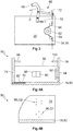
- FIG. 1A is a schematic side view of an embodiment of an inventive device 10 1 for moving charge carriers 12 (see, for example FIG. 9 ).
- the device 10 1 comprises a guide column 14 with a bottom end 15 and a bottom end 17, wherein the guide column 14 is anchored at the bottom end 15 in a bottom plate 16.
- the guide column 14 has a straight, substantially vertical along the in Figure 1A defined z-axis extending first portion 18 and a circular sector-shaped or arcuate second portion 20.
- the provision of the second section 20 is not mandatory.
- the first section 18 comprises a total of three subsections 22, which are identical to one another. Both the subsection 22 of the first section 18 and the annular sector-shaped second section 20 are connected to each other with non-illustrated connecting elements without offset.
- the number of subsections 22 can be chosen freely, so that the height of the guide column 14 can be adjusted accordingly.
- a boom 24 is provided which extends between a housing 26 of the device 10 1 and the annular sector-shaped second portion 20.
- the device 10 1 comprises a carriage 28, which can be moved along the guide column 14.
- the carriage 28 has a number of wheels 30 which roll on the guide column 14, which will be discussed in more detail later.
- a drive device 32 is arranged, with which the carriage 28 along the guide column 14 can be moved. Also on the drive device 32 will be discussed in more detail later.
- the drive device 32 cooperates with a support means 34 running along the guide column 14, which in this case is designed as a chain 36 or as a belt.
- the support means 34 is connected at a first end 38 fixed to the device 10 1 , in the illustrated example in the sector-shaped second section 20 of the guide column 14.
- the support means 34 is of a first guide roller 40 which is fixed to the guide column 14, and a second Deflection pulley 42, which is fixed to the housing 26, deflected. At a second end 44, the support means 34 is secured to the guide post 14 by means of an elastic member 46.
- An adapter 50 1 can be fastened to the carriage 28 by means of a connecting flange 48, which can receive a load carrier 12 (not illustrated here) and can be moved together with the carriage 28 along the guide column 14.
- the housing 26 has a slot-shaped recess (not shown), within which the connection flange 48 can move.
- the connecting flange 48 is shown mounted offset by 90 ° on the carriage 28 about the z-axis, but it is provided that the connecting flange 48 with respect to the Figure 1A is arranged behind or in front of the guide column 14, so that the adapter 50 1 is moved in front of or behind the guide column 14 along this.
- a guide plate 52 is arranged, with which a load not shown here can be guided during emptying from the charge carrier 12.
- the device 10 1 also has a coupling element 54, whose function will be discussed in more detail later.
- the device 10 1 is provided with a housing box 56 in which, for example, not shown electrical and electronic components for controlling the device 10 1 are housed.
- FIG. 1B shown second embodiment of the device 10 2 according to the invention is substantially constructed as the device 10 1 according to the first embodiment.
- a deflecting portion 59 is fixed to the second portion 20, which cooperates with the support means 34 and this leads so that it follows the circular sector-shaped course of the second portion 20.
- a rack 61 is provided in the second section 20, which also follows the circular sector-shaped course of the second section 20 and is formed approximately arcuate. The rack 61 is arranged offset in the y direction to the support means 34.
- the support means 34 extends mostly on the right side of the first section 18 of the guide column 14.
- the second section 20 starting from the first section 18 also to the right. Consequently, the deflecting portion 59 is disposed on the radially inner side of the second portion 20, it being possible to arrange the rack 61 on the radially inner side of the second portion 20 as well FIG. 1B is shown.
- the support means 34 can also largely run on the left side of the guide column 14, so that then the deflection portion 59 is formed so that it leads the support means 34 on the radial outer side of the second portion 20. Accordingly, the rack 61 can extend on the radial outer side of the second section 20.
- the pinion 62 and the further pinion 63 are arranged on a common shaft.
- the rack 61 on the radially outer side and the support means 34 on the radially inner side of the second portion 20 to run or vice versa.
- FIG. 1C A third embodiment of the device according to the invention 10 3, which also, for the most part of the device 10 according to the first embodiment 3 equivalent.
- the support means 34 is designed endlessly, wherein a second deflection roller 65 is arranged at the free end 49 of the guide column 14.
- the device 10 3 comprises the deflection section 59, which deflects the support means 34 in accordance with the course of the second section 20.
- the support means 34 is moved, for which purpose the drive means 32 cooperates with and drives the first deflection roller 42.
- the carriage 28 is fixedly secured to the support means 34 in a suitable manner.
- a rack 61 is not provided.
- FIGS. 2A to 2D are different sectional views along the in Figure 1A defined sectional plane AA through the guide column 14 shown. From the FIGS. 2A to 2C it can be seen that the guide column 14 is a half-H-shaped ( FIG. 2A ), an H-shaped ( FIG. 2B ) or a T-shaped ( Figure 2C ) May have cross-section. In addition, from Figures 2A to 2C, the wheels 30 can be seen, with which the carriage 28 rolls on the guide column 14.
- the wheels 30 can be divided into two groups, namely a first group G1 whose wheels 30 have an axis of rotation parallel to the x-axis, and a second group G2 whose wheels 30 have an axis of rotation parallel to the y -Axis run.
- the wheels 30 may be spaced apart from each other with respect to the z-axis.
- the arrangement of the wheels 30 serves to securely transmit the torques occurring during movement of the adapter 50 1 to the guide column 14.
- At least two wheels 30 per group are provided, which roll on opposite sides of the guide column 14.
- a guide column 14 is shown, which has a substantially T-shaped cross-section, which has two rolling surfaces 57, which at a 45 ° angle to the x-axis and the y-axis. On these rolling surfaces 57 roll off the two wheels 30, which belong to a third group G3, whose axes of rotation extend at an angle of 45 ° to the x-axis and the y-axis.
- Both the in FIGS. 2A and 2B illustrated guide columns 14 with a semi-H-shaped and H-shaped cross-section have two mutually parallel legs 58, between which at least one securing portion 60 extends.
- the securing portion 60 is designed as a securing bolt 53.
- the in the FIGS. 2A and 2B carriage, not shown, 28 is designed so that it does not abut the securing bolt 53.
- illustrated guide column 14 with the T-shaped cross section is different from the other cross sections, which in the Figures 2A, 2B and 2D are shown, also in that the guide column has a cavity 55. Also in the Figures 2A, 2B and 2D illustrated cross sections may have a cavity 55 or more cavities 55. In the event that the guide column 14 has one or more cavities 55, the securing portions 60 may also be formed as through holes 73 opening into the cavity 55.
- FIG. 3 is the drive device 32 shown in more detail, with which the carriage 28 along the guide column 14 can be moved.
- the drive device 32 has a pinion 62, which can be rotated by the drive device 32.
- the support means 34 is formed as a chain 36 or a belt, in which or in which the pinion 62 engages positively.
- the chain 36 or the belt deflected by two support means pulleys 64.
- the carriage 28 is raised or lowered along the guide column 14.
- the inventive device 10 1 , 10 2 , 10 3 has a cooperating with the carriage 28 safety device 66.
- the safety device 66 has a securing element 68, which in the in FIG. 3 illustrated embodiment is configured hook-shaped.
- the securing element 68 is rotatably mounted about the y-axis (see. Figures 1A and 1B ) and is biased by a biasing means 70, in the example shown with a spring.
- the spring can be biased, the securing element 68 is connected to a counter-holder 72, which is supported on the chain 36 or on the belt, so that the securing element 68 in the in FIG. 3 shown first position is held.
- the counter-holder 72 can bias the spring 70 only because the chain 36 or the belt is sufficiently tightened and thus can hardly deflect in the direction of action and in the opposite direction of the biasing force provided by the spring 70.
- the securing element 68 is in the first position, the carriage 28 can be moved along the guide column 14. In the event that the chain 36 or the belt breaks, the carriage 28 moves down uncontrollably along the guide column 14. In this case, however, the chain 36 or the belt can be deflected in the effective direction and the opposite direction of the biasing force provided by the spring 70, so that the spring can no longer be biased. Consequently, the securing element 68 is rotated about the y axis in a direction not shown with the arrow P direction in a second position, not shown.
- the securing element 68 in the in figure 2 B engage shown securing bolt 61, so that the carriage 28 is detected on the guide column 14 and no longer can fall uncontrollably along the guide column 14 down.
- a non-illustrated counterweight can be used, which rotates the securing element 68 in the second position in the event that the chain 36 or the belt breaks.
- the securing element 68 can also engage in the through-opening 73.
- FIG. 1C a further embodiment of the safety device 66 is shown.
- a locking toothing 67 is arranged on the guide column 14.
- the fuse element 68 can be biased in the above-mentioned manner in the illustrated in broken lines first position in which the securing element 68 does not engage in the locking teeth 67.
- the carriage 28 can be moved in both directions along the guide column 14. If the support means 34 tears, the securing element 68 is placed in the second position, which is shown by the solid lines. In the second position, the securing element 68 engages in the locking toothing 67 and sets the carriage 28 so tight that it can no longer be moved downwards.
- the device 10 2 , 10 3 a chassis 69, with which the device 10 2 , 10 3 is movable.
- the chassis 69 includes a number of wheels 71, of which at least one is driven by a drive unit not shown in detail.
- the device 10 2 , 10 3 according to the second and third embodiments can be integrated into a driverless transport system.
- the carriage 28 can be moved together with the adapter 50 along the guide column 14. Due to the manner of the embodiment of the support means 34, the carriage 28, the circular sector-shaped second portion 20 of the guide column 14 almost completely through, wherein the carriage 28 and consequently the adapter 50 1 on the path predetermined by the second portion 20 of the guide column 14 around the y -Axis are turned.
- the angle of rotation ⁇ is in Figure 1A marked and there is 150 °. In a corresponding design of the circular sector-shaped second portion 20, it may also be up to 180 °.
- the cargo contained in the charge carrier 12 is poured out in this way gently and directed by the guide plate 52 so that it can be transferred to a receptacle, not shown.
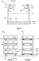
- FIG. 4A is a first embodiment of an adapter according to the invention 50 1 based on a basic front view and in FIG. 4B shown by a schematic side view.
- the adapter 50 1 has a first side wall 74 and a second side wall 76 which are substantially parallel to each other.
- the adapter 50 1 comprises a support section 78 on which at least one charge carrier 12 can be placed.
- the support section 78 is in the first embodiment of the adapter 50 1 as a plate bottom 80 in which a gap 82 is inserted, along which the first side wall 74 can be moved.
- the adapter 50 1 has an adjusting device 84 which, for example, comprises a spindle with which the first side wall 74 can be pushed toward the second side wall 76 and away from it. In this way, the distance between the two side walls 74, 76 can be adapted to the width or the length of the load carrier 12.
- FIG. 4B recognizable, the plate bottom 80 to the front and back with the side walls 74, 76 flush.
- the adapter 50 1 between the side walls 74, 76 extending a rear wall 86, to which a sensor 88 for detecting the presence of a charge carrier 12 in the adapter 50 1 and / or in the immediate vicinity of the adapter 50 1 and a read head 90 to identify and documenting the received charge carriers 12 are attached.
- the rear wall 86 has a slightly lower height than the side walls 74, 76.
- the second side wall 76 has a wall portion 92 which can be biased by a biasing means 94.
- the distance between the first side wall 74 and the wall portion 92 is selected to be slightly less than the length or width of the charge carrier 12.
- the biasing force provided by the biasing means 94 generates a frictional force between the charge carrier 12 and the first side wall 74 and the wall portion 92, so that the charge carrier 12 on the one hand clearly in position with respect to the side walls 74, 76 positioned in the adapter 50 1 and on the other hand held due to the frictional force in the charge carrier 12 and secured against slipping out.
- the adapter 50 1 can be connected to the carriage 28, for which purpose the carriage 28 has the already mentioned connection flange 48.
- FIG. 4B it can be seen that the side walls 74, 76 have a first group Q1 of diamond-shaped through holes 96.
- the through holes 96 of the first group Q1 are used to attach the adapter 50 1 to the connection flange 48 (see. FIG. 1 ).
- a first stop 98 and on the second side wall 76 a second stop 100 is attached.
- the charge carrier 12 is fixed between the plate bottom 80 and the stops 98, 100, so that the charge carrier 12 can not fall out of the adapter 50 1, in particular when the adapter 50 1 along the sector-shaped second portion 20 of Guide column 14 is moved.
- FIG. 5 a second embodiment of the adapter 50 2 according to the invention is shown with reference to a side view.
- the adapter 50 2 according to the second embodiment is largely similar to that of the first embodiment, however, an extension portion 10 2 are connected to the plate bottom 80, whereby even longer charge carriers 12 can be safely accommodated in the adapter 50 2 .
- FIG. 6 a third embodiment of the adapter 50 3 according to the invention is shown with reference to a basic front view.
- the support portion 78 is not formed by a plate bottom 80 but by a first roller 104 disposed on the first side wall 74 and a second roller 106 disposed on the second side wall 76.
- the rollers 104, 106 can be driven by means of a drive unit, not shown, so that a charge carrier 12 can be pulled into the adapter 50 3 and pushed out of it again.
- the rear wall 86 is provided with the joints 82 along which the side walls 74, 76 can be shifted towards and away from each other.
- FIG. 7 a fourth embodiment of the adapter 50 4 according to the invention is shown with reference to a schematic side view.
- the adapter 50 4 according to the fourth embodiment is substantially similar to that of the first embodiment (see FIGS. 4A and 4B ), wherein the plate bottom 80 without extension portion 10 2 projects forward over the side walls 74, 76.
- an extension runner 108 is connected to the first side wall 74 and the second side wall 76 using a second group Q2 of through holes 96, respectively.
- the first stop 98 and the second stop 100 are not attached to the side walls 74, 76, but to the extension runners 108. How out FIG.
- extension runners 108 have two second groups Q2 of the through-holes 96, so that further extension runners 108 can be attached to the extension runners 108 shown.
- the distance between the support portion 78 and the Stops 98, 100 are increased, so that even higher charge carriers 12 in the adapter 50 4 can be added.
- FIG. 8 illustrated fifth embodiment of the adapter 50 5 has a chute 110 for guiding the cargo when emptying the charge carrier 12.
- the rear wall 86 has a greater height than the side walls 74, 76 and therefore projects upwardly beyond the side walls 74, 76.
- the protruding part of the rear wall 86 is part of the pouring device 110.
- the pouring device 110 comprises two guide sections 112, which are movably fastened to the side walls 74, 76 and with which a bulk taper 114 can be adjusted.
- arcuate slots 116 are provided, which are penetrated by fastening means 118. The once set position of the guide portions 112 relative to the rear wall 86 can be fixed with the fastening means 118.
- the adapter 50 5 according to the fifth embodiment, a drip pan 120, with which in particular liquids can be collected.
- liquids may be lubricants or coolants which are used in the manufacture of the cargo and only slowly detach from the load.
- the plate bottom 80 is provided with drain holes 122, so that the liquid discharged from the load can flow into the collecting trough 120.
- the drip pan 120 is quickly detachably connected to the adapter 50 5 so that it can be easily separated from the adapter 50 5 , emptied and connected to the adapter 50 5 again.
- FIGS. 9A is a first embodiment of a trolley 124 1 according to the invention based on a principal Side view and in FIG. 9B illustrated by a basic front view.
- the transport carriage 124 1 has a carrier device 125 with two first side carriers 126 and two second side carriers 128.
- six first support rollers 132 are fastened to the first side support 126 per floor and six second support rollers 132 are supported on the second side support 128, wherein the number of floors and the number of first and second support rollers 132 can be selected largely freely.
- the transport carriage 124 1 serves to receive the load carrier 12.
- the carrier rollers 132 may be driven by a drive unit, not shown, so that the charge carriers 12 can be placed at one end of a floor on the support rollers 132 and moved within this floor until they themselves in the desired position.
- the first and second carrier rollers 132 are spaced from each other.
- the trolley 124 1 accordingly has no continuous support rollers. At least one of the side supports 126, 128, on the other hand, the side support 126, 128 toward and away from this movable.
- the transport carriage 124 1 guide rods 134, which are arranged so that they do not collide with the charge carriers 12.
- the distance between the side beams 126, 128 is chosen so that it substantially corresponds to the length or the width of the charge carriers 12.
- the side supports 126, 128 guide the charge carriers 12 within the trolley 124 1 and thus ensure an appropriate alignment and security. Even if it suffices for only one of the side supports 126, 128 to be designed to be movable, it is advisable to move the two side supports 126, 128 in synchronism with one another and away from one another. In this way it is ensured that the trolley 124 1 evenly loaded and the risk of tipping over due to a one-sided load is kept low.
- the trolley 124 1 is equipped with wheels 136 so that the trolley 124 1 can be moved by an employee.
- the transport vehicle 124 1 has a track 138, with which the transport vehicle 124 1 without the help of an employee, especially within the factory and thus for internal transport is movable.
- the transport carriage 124 1 comprises a drive unit 140.
- induction loops or the like may be installed in the floor of the workshop to specify the path along which the transport carriage 124 1 is moved.
- FIG. 10 is a second embodiment of the trolley 124 2 2 illustrated by a schematic representation.
- the trolley 124 2 is equipped with a drip pan 142, with which liquids or solids used in the production of the cargoes and only slowly separate from the load, can be collected.
- the transport carriage 124 2 has at least one extension section 144, which is arranged in the illustrated embodiment in the third floor. In this way, the capacity of the trolley 124 2 can be increased. But it is also possible to use the extension section 144 in particular for the support of the charge carrier 12 during the transfer. The transfer of the charge carriers 12 to the transport carriage 124 2 can be simplified due to better accessibility. In this case, the extension portion 144 can be inserted into the side support 126, 128. It can be provided that the extension section 144 between the various levels of the trolley 124 2 is movable.
- the transport carriage 124 2 is equipped with a coupling device 146.
- the trolley 124 2 can be coupled with a coupling partner.
- a coupling partner can, for example, the in Figure 1A shown device 10 1 for moving carriers 12 or a further transport carriage 124, not shown.
- the device 10 1 has the coupling element 54, which can be coupled to the coupling device 146 solely as a result of a corresponding positioning of the transport carriage 124 2 .
- the coupling device 146 and the coupling element 54 may be designed so that the transport carriage 124 2 is fixed in the coupled state in its position and can not roll away.
- an electrically conductive contact between the coupling element 54 and the coupling device 146 can be made in the coupled state, so that electrical energy and electrical signals between the device 10 1 and the trolley 124 2 can be replaced.
- pneumatic, electromagnetic and / or hydraulic connections 152 are integrated in the coupling device 146 and the coupling element 54, so that compressed air and / or hydraulic fluid and / or electrical energy can be transmitted.
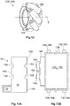
- FIGS. 13A and 13B An embodiment of the coupling element 54 and the coupling device 146 is shown in greater detail on the basis of a basic plan view.
- the coupling element 54 is connected to the bottom plate 16 of the device 10 1 and has at a left edge 154 and a right edge 156 in each case two recesses 158, in which two corresponding Projections 160 of the coupling device 146 can be introduced.
- the trolley 124 is clearly positioned and aligned with respect to the device 10 1 .
- an embodiment of the coupling device 146 in which instead of the recesses 158 vertically extending rods are provided, in which corresponding claws of the trolley 124 engage.
- the jaws may be attached at various heights of the trolley 124. A positioning and alignment of the trolley 124 is still possible, as long as the jaws can engage in the rods.
- the transport carriage 124 2 has a number of receiving portions 162.
- a forklift can grab the trolley 124 2 , lift and drive through the workshop.
- the forklifts can drive autonomously themselves, so that in this way the transport carriage 124 2 can be moved automatically without the need for a moving unit 138 or a drive unit 140.
- a 360 ° all-round view for position sensors not shown, arranged on the transport carriage 124 2 can be provided, which is crucial for the smooth operation of driverless transport systems (FTS).
- FTS driverless transport systems
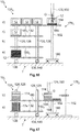
- FIG. 11A and 11B is a third embodiment of the trolley 124 3 according to the invention each shown in a front view.
- the transport carriage 124 3 has a locking device 148, with which the charge carriers 12, which are arranged in the transport carriage 124 3 , can be secured.
- the locking device 148 has a number of locking bars 150, which on the side supports 126, 128 are adjustably mounted.
- the locking device 148 is in an open position, in which the locking bars 150 are vertically aligned, so that the load carriers 12 can be transported from the front or from behind on the trolley 124 3 and removed from this again.
- 11B is the locking device 148 in the locked position in which the locking bars 150 are aligned horizontally so that they secure the carriers 12 in the trolley 124 3 .
- the adjustment of the locking bar 150 between the open position and the locking position can be done by means of a central, not shown lever, so that the adjustment can be done quickly and easily. Alternatively or cumulatively, the adjustment can also take place by means of a motor or actuating cylinder, not shown.
- Also not shown is an embodiment of the trolley 124, in which the locking bars 150 are non-rotatably mounted on the trolley 124, but are movable in the vertical direction. In this embodiment, the locking position corresponds to those in FIG. 11B is shown. To get into the open position, the locking bars 150 are relative to the in FIG.
- 11B selected representation shifted down until they are aligned with the support rollers 132 or as far as positioned under the support rollers 132, so that the charge carriers 12 can be removed from the trolley 124.
- two barrier bars 150 which are arranged on the same floor of the trolley, can be combined to form a continuous barrier bar 150.
- a wheel 136 designed as a mecanum wheel 164 is shown by means of a perspective view.
- On the circumference of the Mecanum wheel 164 are several, in this case barrel-shaped Rollers 166 arranged at an angle of 45 degrees to the rotational axis T of the entire Mecanum wheel 164 and rotatably mounted on mounting portions 168. Only these wheels 166 make contact with the ground. These rollers 166 have no direct drive and can rotate freely about their oblique bearing axis.
- the transport carriage 124 whether with its own drive or by an employee, can be moved omnidirectionally without the need for a steering device.
- the wheels 136 of the track 138 are designed as mecanum wheels 164.
- the transport carriage 124 2 has a storage rack 170, which is carried out separately from the track unit 138.
- the storage rack 170 includes the side supports 126, 128, the carrier rollers 132 and the collecting trough 142 attached thereto.
- the storage rack 170 can be parked, for example by means of a forklift, not shown, using the receiving portions 162 on the particular autonomously moving trajectory 138.
- the trajectory 138 can therefore be used for various storage shelves 166.
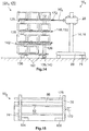
- FIG. 14 A fourth embodiment of the device 10 according to the invention 4 is shown which includes the transport carriage 124 4 according to a fourth embodiment.
- the essential difference from the third exemplary embodiment lies in the design of the coupling device 146.
- the coupling device 146 is not arranged at the bottom of the transport carriage 124 4 . Rather, in each floor of the trolley 124 4 each a group of terminals 152 are arranged, which in each case can be connected to a counterpart 172, which is arranged on the adapter 50 6 , the in figure 15 is shown separately.
- electrical energy, control signals and / or pneumatic or hydraulic fluids between the trolley 124 4 and the adapter can be replaced.
- only one floor of the transport carriage 124 4 is coupled, so that, for example, only the drive units of the support rollers 132 of this floor are supplied with power to drive the respective support rollers 132.
- the supply and removal of the load carrier 12 to or from the trolley 124 4 using the driven carrier rollers 132 is thereby possible without corresponding lines between the floors must be laid.
- FIG. 15 illustrated sixth embodiment of the adapter 50 6 has in relation to FIG. 6 illustrated third embodiment 50 3 the following further difference: While the in FIG. 6 shown adapter 50 3 has the first and the second stop 98, 100, has the in FIG. 15 Adapter 50 6 shown with a continuous retainer rod 175. In this way, even very narrow carriers 12 can be secured against falling out, without the need for the first side wall 74 must be moved to the second side wall 76 as far until that both stops 98, 100 cooperate with the carriers 12 can.
- the provision of the continuous support rod 175 is particularly suitable for adapters 50, which have immovable side walls 74, 76. In the FIG.
- the through-holes 96 can be used to arrange the support rod 175 at different heights on the adapter 506 in order to implement an adaptation to different levels of charge carriers 12 can.
- the through-holes 96 can also be designed as elongated holes, so that a very precise height adjustment is possible.
- All wheels 71, 136 may also be configured as mecanum wheels 164 (cf. FIG. 13B ).
- FIG. 16 is a fifth embodiment of an inventive device 10 5 for guiding charge carriers 12 to a loading and / or unloading station 176 and shown away therefrom on the basis of a basic representation.
- the device 10 1 comprises the transport carriage 124 5 according to a fifth embodiment and a movement device 178 1 according to a first embodiment.
- the structure of the trolley 124 5 largely corresponds to those of the embodiments described above.
- the trolley 124 5 four levels a) to d). In each case four levels a) to d), six first carrier rollers 132 are attached to the first side carriers 126 and six second carrier rollers 132 are attached to the second side carriers 128, respectively.
- the carrier rollers 132 of the levels c) and d) each form a first receiving area 180 1 and the carrier rollers 132 of the levels a) and b) each have a second receiving area 180 2 on which the carrier 12 which is in this case can be stored.
- the carrier rollers 132 can be driven by means of a drive unit, not shown.
- the movement device 178 1 has a lifting column 182, with which a cross member 184 can be raised and lowered.
- the lifting column 182 is supported by a bottom plate 186.
- On the cross member 184 five drivable cross member rollers 188 are fixed in this case, with a different number of cross member rollers 188 can be used.
- the device 10 5 is operated in the following manner:
- the trolley 124 5 is loaded in any position with in this case a total of six load carriers 12, which are stored on the two first receiving areas 180 1 .
- the charge carriers 12 are in a first state, in which they are empty in the illustrated example, that is, do not receive any load G. But they can also be filled with cargo G in the first state.
- the loaded dolly 124 5 is automatically in this case by means of the track 138 in an in FIG. 16 shown transfer position T driven.
- the transfer position T is characterized in that a transfer of the charge carriers 12 from the transport vehicle 124 5 to the movement device 178 1 and vice versa is possible.
- the cross member 184 of the movement device 178 1 is moved by means of the lifting column 182 so that it is aligned with one of the first receiving areas 180 1 . Subsequently, the respective carrier rollers 132 of the transport carriage 124 5 are rotated so that one of the load carriers 12 is moved by the transport carriage 124 5 on the cross member rollers 188, which are also rotated accordingly. In the illustrated case, the second charge carrier 12 has been transferred to the plane c). Subsequently, the cross member 184 is moved to the loading and / or unloading station 176, which is done in this case by lifting the cross member 184. As in FIG.
- the loading and / or unloading station 176 may include, for example, an outlet tube 190, from which the load G can be discharged.
- the charge carrier 12 is moved so close to the loading and / or unloading station 176 that the load G can be safely introduced into the load carrier 12.
- the loading and / or unloading station 176 is set up only for loading the load carriers 12, but not for unloading them.
- the charge carrier 12 After the charge carrier 12 has been completely filled, it is in the second state and is deposited on one of the second receiving sections 180 2 of the transport carriage 124 1 , as shown for the first charge carrier 12, which has been taken from the plane c). This charge carrier 12 has been deposited on the second receiving area 180 2 of the plane a).
- the cross member 184 is lowered accordingly and the cross member rollers 188 and the support rollers 132 is set in a corresponding rotation, so that the charge carrier 12 can be transferred from the cross member 184 to the respective second receiving portion 180 2 .
- the charge carrier 12 has been converted into the second state. Loading and / or unloading of the charge carriers 12 on the first receiving area 180 1 is also possible.
- the charge carriers 12 can also be filled with the load G in the first state.
- the loading and / or unloading station 176 is set up so that it can remove the load G to be processed from the load carriers 12, feed it to a processing machine, not shown, and then reintroduce the processed load G into the load carrier 12.
- the charge carrier 12 is transferred to the second state by filling the processed load G.
- the transport carriage 124 1 can be moved away from the transfer position T, for example to a warehouse where the processed load G is stored or sent. Once the transfer position T has become free, another trolley 124 1 driven to the transfer position T and the above steps are performed again.
- the first receiving portions 180 1 in the levels c) and d) and the second receiving portions 180 2 in the planes a) and b) are arranged.
- 180 1 , 180 2 three charge carriers 12 can be stored per receiving area, so that the trolley 124 1 is loaded with a total of six charge carriers 12.
- the carriers 12 are moved from planes c) and d) to planes a) and b).
- a first receiving area 180 1 are deposited on the charge carrier 12 in the first state, when performing the above steps to a second receiving area 180 2 , are stored on the charge carrier 12 in the second state.
- the dolly 124 1 can be loaded more, which increases the effectiveness of its use.
- FIG. 17 a sixth embodiment of the device 10 6 according to the invention is shown.
- stackable, tray-shaped trays 174 are used.
- the device 10 6 comprises a trolley 124 6 according to a sixth embodiment, which has only the planes a) and b). In the plane b), the first receiving areas 180 1 and in the plane a), the second receiving portions 180 2 are arranged.
- the basic handling of the trays 174 corresponds to that for the in FIG. 16 shown charge carrier 12 has been explained.
- the trays 174 are distributed over several, in this case three stacks.
- the trolley 124 6 is loaded so that the three stacks of empty trays 174 in this case are placed on the first receiving area 180 1 .
- the empty trays 174 are in the first state. If the transport carriage 124 1 is in the transfer position T, one of the stacks is transferred to the movement device 178 2 by a corresponding rotation of the carrier rollers 132 and the crossbar rollers 188.
- the trays 174 have separate receiving spaces, in which usually a single load G is stored. This results in the fact that only the tray 174 of a stack can be loaded, which is not covered by another tray 174 upwards.
- the movement device 178 2 comprises a gripping device 192, with which the trays 174 can be detected and moved from one stack to another stack. Once the top tray 174 of the transferred stack is filled, it is detected by the gripping device 192 and transported from the transferred stack to another stack. Consequently, during the filling of the trays 174, two stacks are provided on the cross member 184. After all trays 174 are filled and thus transferred to the second state, only one stack is left on the cross member 184, which has exclusively filled trays 174. This stack is deposited on the second receiving area 180 2 of the transport carriage 124 6 .
- the gripping device 192 may lift only the upper three trays 174, for example. Subsequently, the stack is moved with the lower seven trays 174 by a corresponding rotation of the cross member rollers 188 so that the top Tray 174 of the stack for the loading and unloading station 176 is accessible. The top of the seven trays 174 is then loaded and unloaded. The stack is then moved back to the starting position and the remaining upper three trays 174 of the gripping device 192 again stored. In this case, there is only one stack on the cross member 184 since the gripper 192 lifts the top three trays 174 until the stack with the seven bottom trays 174 has returned to the home position. If necessary, the upper three trays 174 of the gripping device 192 can be temporarily stored on the cross member 184. Thus, each tray 174 can be loaded and unloaded regardless of the stacking order.
- the trays 174 may be loaded in the first state with load G, which is removed from the receiving spaces for processing and then stored there again. The trays 174 are then transferred to the second state when they are filled exclusively with the processed load G.
Landscapes
- Engineering & Computer Science (AREA)
- Mechanical Engineering (AREA)
- Transportation (AREA)
- Structural Engineering (AREA)
- Civil Engineering (AREA)
- Life Sciences & Earth Sciences (AREA)
- Geology (AREA)
- Warehouses Or Storage Devices (AREA)
Abstract
Die vorliegende Erfindung betrifft eine Vorrichtung zum Bewegen von Ladungsträgern (12), in welchen ein Ladegut einbringbar ist, umfassend eine Führungssäule (14) mit einem bodennahen Ende (15) und einem bodenfernen Ende (17), einen Schlitten (28), welcher entlang der Führungssäule (14) bewegbar ist und mit welchem zumindest ein Adapter (50) zum Aufnehmen von Ladungsträgern (12) verbindbar ist, zumindest ein entlang der Führungssäule (14) verlaufendes Abstützmittel (34), ein im Schlitten (28) angeordnetes oder mit dem Schlitten zusammenwirkendes und mittels einer Antriebseinrichtung (32) antreibbares Ritzel (62), welches zum Bewegen des Schlittens (28) entlang der Führungssäule (14) formschlüssig in das Abstützmittel (34) eingreift, und eine im Bereich des bodennahen Endes (15) an der Führungssäule (14) befestigte erste Umlenkrolle (42) zum Umlenken des Abstützmittels (34).The present invention relates to a device for moving load carriers (12), in which a load can be introduced, comprising a guide column (14) with a bottom end (15) and a bottom end (17), a carriage (28) which along the guide column (14) is movable and with which at least one adapter (50) for receiving charge carriers (12) is connectable, at least one along the guide column (14) extending support means (34), in the carriage (28) arranged or with the Carriage cooperating and by means of a drive device (32) drivable pinion (62) which engages for moving the carriage (28) along the guide column (14) positively in the support means (34), and in the region of the bottom end (15) on the Guide column (14) fixed first guide roller (42) for deflecting the support means (34).
Description
Die vorliegende Erfindung betrifft eine Vorrichtung zum Bewegen von Ladungsträgern. Des Weiteren betrifft die Erfindung einen Adapter zum Aufnehmen von Ladungsträgern sowie einen Transportwagen zum Aufnehmen und Transportieren von Ladungsträgern.The present invention relates to a device for moving charge carriers. Furthermore, the invention relates to an adapter for receiving charge carriers and a transport trolley for receiving and transporting load carriers.
Ladungsträger werden in der Logistik sehr häufig verwendet, um ein Ladegut zu transportieren und zu lagern. Die am häufigsten anzutreffenden Ausführungsformen von Ladungsträgern sind Kisten und Paletten. Die Kisten werden häufig auch als Kleinladungsträger (KLT) bezeichnet. Der wesentliche Vorteil der Ladungsträger ist, dass diese standardisiert und mit Greifeinheiten unabhängig von der Form des Ladeguts ergriffen und bewegt werden können, ohne dass es hierzu besonderer Anpassungen der Greifeinheiten bedarf. Bei der Verwendung von Kisten ergibt sich die Möglichkeit, diese zu stapeln, wodurch auf einer geringen Fläche eine große Menge des Ladeguts gelagert und transportiert werden kann.Load carriers are used very frequently in logistics in order to transport and store a load. The most commonly encountered embodiments of load carriers are boxes and pallets. The boxes are often referred to as small load carriers (KLT). The main advantage of the load carriers is that they can be standardized and grasped and moved with gripping units, regardless of the shape of the load, without requiring special adjustments of the gripping units for this purpose. When using boxes, it is possible to stack them, which can be stored and transported on a small area a large amount of the cargo.
Zu den Ladungsträgern zählen auch sogenannte Trays, die tablettförmig ausgebildet sind und meist mehrere Aufnahmeräume aufweisen, in welche typischerweise ein Ladegut, insbesondere ein Stückgut, abgelegt werden kann. Die Aufnahmeräume sind durch Wände voneinander getrennt, so dass ein Ladegut, welches in einem Aufnahmeraum abgelegt ist, nicht in Berührung mit einem anderen Ladegut kommen kann. Aus derartigen Berührungen resultierende Beschädigungen des Ladeguts können unter Verwendung von Trays verhindert werden. Derartige Trays werden auch als Blister bezeichnet. Auch wenn die Trays ebenfalls Ladungsträger sind, sollen im Folgenden unter Ladungsträger die kistenförmigen Ladungsträger als Abgrenzung zu den tablettförmigen Trays verstanden werden. Wenn nicht anders angegeben, gelten die folgenden Ausführungen für Ladungsträger und Trays Gleichermaßen.The load carriers also include so-called trays, which are tray-shaped and usually have a plurality of receiving spaces, in which typically a load, in particular a piece goods, can be stored. The receiving spaces are separated by walls, so that a load, which is stored in a receiving space, can not come into contact with another load. Damage to the cargo resulting from such contact can be prevented by using trays. Such trays are also referred to as blisters. Even if the trays are also carriers In the following, under charge carriers, the box-shaped charge carriers are to be understood as a distinction from the tray-shaped trays. Unless otherwise stated, the following embodiments apply equally to carriers and trays.
Eine besondere Situation ergibt sich beim Befüllen und Entleeren der Ladungsträger: Ein von einer Werkzeugmaschine fertig bearbeitetes Werkstück muss weitertransportiert werden, beispielsweise zu einem Lager, wo das Werkstück gelagert und von wo aus es versendet werden kann. Je nach Ausführungsform der Werkzeugmaschine wirft diese das fertig bearbeitete Werkstück aus oder legt es in einem Abgabebereich ab. Die Werkzeugmaschine kann so eingerichtet werden, dass sie das fertig bearbeitete Werkstück direkt in den Ladungsträger ablegt. Ist der Ladungsträger voll, muss dieser gegen einen unbefüllten Ladungsträger ausgetauscht werden. Sofern kein Förderband vorhanden ist, wird dieser Austausch manuell durchgeführt, wobei der befüllte Ladungsträger beispielsweise auf einen Transportwagen oder einem Stapelplatz abgelegt oder abgestellt wird. In vielen Fällen wiegen die befüllten Ladungsträger bis zu 70 kg, so dass das manuelle Heben und Ablegen eine Gesundheitsgefährdung für den betreffenden Mitarbeiter darstellt.A special situation arises when filling and emptying the load carriers: a workpiece finished by a machine tool must be transported further, for example to a warehouse, where the workpiece can be stored and from where it can be shipped. Depending on the embodiment of the machine tool, it ejects the finished workpiece or deposits it in a dispensing area. The machine tool can be set up so that it deposits the finished workpiece directly into the load carrier. If the load carrier is full, it must be replaced with an unfilled load carrier. If no conveyor belt is present, this replacement is carried out manually, wherein the filled charge carrier is stored or parked for example on a trolley or a stacking place. In many cases, the filled load carriers weigh up to 70 kg, so manual lifting and lowering poses a health hazard to the employee.
Um das Heben und Ablegen zu erleichtern, sind verschiedene Hubvorrichtungen entwickelt worden. Beispielsweise in der
Nicht nur bei der in der
Wie bereits erläutert, wird das Ladegut in Ladungsträgern transportiert und gelagert. Beim Bewegen der Ladungsträger mittels einer zuvor beschriebenen Vorrichtung werden die Ladungsträger in den bereits erwähnten Adapter aufgenommen und zusammen mit dem Adapter bewegt. Um eine sichere Aufnahme des Ladungsträgers im Adapter zu gewährleisten und insbesondere ein Verrutschen des Ladungsträgers im Adapter oder ein Herausfallen des Ladungsträgers aus dem Adapter zu verhindern, muss die Form und die Größe des Adapters an die Form und die Größe des Ladungsträgers angepasst werden. Diese Anforderung führt in der Praxis dazu, dass ein Adapter nur für einen Typ oder nur für sehr wenige Typen von Ladungsträgern verwendbar ist. Es kann aber durchaus sein, dass innerhalb des innerbetrieblichen Transports mehrere Typen von Ladungsträgern verwendet werden, so dass die Adapter nicht mehr passen und ausgetauscht werden müssen, was im laufenden Betrieb nicht machbar ist. Hierdurch werden der Anwendungsbereich und die Flexibilität von bekannten Vorrichtungen deutlich eingeschränkt.As already explained, the load is transported and stored in load carriers. When moving the charge carriers by means of a device described above, the charge carriers are taken up in the aforementioned adapter and moved together with the adapter. In order to ensure a secure recording of the charge carrier in the adapter and in particular to prevent slippage of the charge carrier in the adapter or falling out of the charge carrier from the adapter, the shape and size of the adapter must be adapted to the shape and size of the carrier. This requirement in practice means that an adapter can only be used for one type or only for very few types of load carriers. However, it may well be that within the in-house transport several types of carriers are used, so that the adapter no longer fit and must be replaced, which is not feasible during operation. As a result, the scope and flexibility of known devices are significantly limited.
Wie ebenfalls erwähnt, dienen die Ladungsträger nicht nur für den Transport des Ladeguts, sondern auch zum Lagern des Ladeguts. Eine temporäre Lagerung des Ladeguts innerhalb des innerbetrieblichen Transports kann beispielsweise dann notwendig sein, wenn die fertig bearbeiteten Ladegüter in einem Lager gelagert werden, welches sich mehr oder weniger weit weg von den Werkzeugmaschinen befindet. In diesem Fall werden die Ladungsträger auf einem Transportwagen abgelegt und zwischengelagert. Wenn der Transportwagen voll beladen ist, wird dieser in das Lager geschoben. Aber auch hier tritt die für die Adapter beschriebene Situation auf, wonach die Ladungsträger nur dann sicher im Transportwagen aufgenommen werden können, wenn die Größe der Ladungsträger zu den Größen der Ablageplätze des Transportwagens passt. Wenn innerhalb eines innerbetrieblichen Fördersystems mehrere Typen von Ladungsträgern verwendet werden, müssen passende Transportwagen vorgehalten werden, wodurch die Transportabläufe komplexer, aufwendiger und daher fehleranfälliger und teurer werden.As also mentioned, the load carriers not only serve for the transport of the load, but also for the storage of the load. A temporary storage of the cargo within the in-house transport, for example, be necessary if the finished goods are stored in a warehouse, which is more or less far away from the machine tools. In this case, the load carriers are placed on a trolley and stored temporarily. When the trolley is fully loaded, it is pushed into the warehouse. But even here, the situation described for the adapter occurs, according to which the charge carriers can only be safely accommodated in the transport vehicle, if the size of the carrier to the sizes of the storage spaces of the Transport trolley fits. If several types of load carriers are used within an in-house conveyor system, suitable transport trolleys must be provided, which makes the transport processes more complex, time-consuming and therefore error-prone and more expensive.
Aufgabe einer Ausführungsform der vorliegenden Erfindung ist es, eine Vorrichtung zum Bewegen von Ladungsträgern zu schaffen, mit welcher der oben geschilderten Situation begegnet werden kann. Insbesondere soll die Vorrichtung so gestaltet sein, dass die Gefahr von Verletzungen für einen Benutzer gegenüber bekannten derartigen Vorrichtungen deutlich verringert wird. Des Weiteren liegt einer Ausführungsform der vorliegenden Erfindung die Aufgabe zugrunde, einen Adapter und einen Transportwagen zu schaffen, welche für unterschiedlich große Ladungsträger verwendbar sind.
Diese Aufgabe wird mit den in Anspruch 1 angegebenen Merkmalen gelöst. Vorteilhafte Ausführungsformen sind Gegenstand der Unteransprüche.It is an object of one embodiment of the present invention to provide a device for moving charge carriers, with which the above-described situation can be met. In particular, the device should be designed so that the risk of injury to a user over known such devices is significantly reduced. Furthermore, an embodiment of the present invention has the object to provide an adapter and a trolley, which can be used for different sized carriers.
This object is achieved with the features specified in claim 1. Advantageous embodiments are the subject of the dependent claims.
Eine Ausführungsform der Erfindung betrifft eine Vorrichtung zum Bewegen von Ladungsträgern, in welchen ein Ladegut einbringbar ist, umfassend eine Führungssäule, einen Schlitten, welcher entlang der Führungssäule bewegbar ist und mit welchem zumindest ein Adapter zum Aufnehmen von Ladungsträgern verbindbar ist, zumindest ein entlang der Führungssäule verlaufendes Abstützmittel, und ein im Schlitten angeordnetes oder mit dem Schlitten zusammenwirkendes und mittels einer Antriebseinrichtung antreibbares Ritzel, welches zum Bewegen des Schlittens entlang der Führungssäule formschlüssig in das Abstützmittel eingreift.An embodiment of the invention relates to a device for moving load carriers, in which a load can be introduced, comprising a guide column, a carriage which is movable along the guide column and with which at least one adapter for receiving charge carriers is connectable, at least one along the guide column extending support means, and arranged in the carriage or cooperating with the carriage and drivable by means of a drive means pinion, which engages positively for moving the carriage along the guide column in the support means.
Unter einem Ritzel kann ein Zahnrad verstanden werden, das Ritzel kann aber auch als ein Rad ausgestaltet sein, welches ein bestimmtes Profil aufweist, das formschlüssig mit dem Abstützmittel zusammenwirkt. Das Abstützmittel stellt eine Art Zahnstange dar. Auf jeden Fall muss ein Durchrutschen des Ritzels gegenüber dem Abstützmittel verhindert werden, da sich sonst der Schlitten unkontrollierbar entlang der Führungssäule bewegen würde. Das Abstützmittel ist flexibel und insbesondere als ein Seil, eine Kette oder als ein Riemen ausgebildet. Die flexible Ausgestaltung des Abstützmittels insbesondere als Kette, Seil oder Riemen hat den Vorteil, dass die Führungssäule auch gebogene Abschnitte aufweisen kann, ohne das Abstützmittel auf die bogenförmigen Abschnitte anpassen zu müssen. Aufgrund der Flexibilität der Kette, des Seils oder des Riemens können diese für unterschiedlich ausgestaltete Führungssäulen verwendet werden. Zudem kann die Anordnung des Ritzels freier gewählt werden, da das unabhängig von der Position mit diesem zusammenwirken kann. Die Gestaltungsfreiheit der Antriebseinrichtung wird hierdurch erhöht.A pinion may be understood to mean a toothed wheel, but the pinion may also be designed as a wheel which has a specific profile which interacts with the support means in a form-fitting manner. The support means is a kind of rack. In any case, slippage of the pinion against the support means must be prevented, otherwise the carriage would move uncontrollably along the guide column. The support means is flexible and in particular designed as a rope, a chain or a belt. The flexible design of the support means, in particular as a chain, rope or belt has the advantage that the guide column can also have curved sections without having to adapt the support means to the arcuate sections. Due to the flexibility of the chain, the rope or the belt, these can be used for differently designed guide columns. In addition, the arrangement of the pinion can be chosen freely because it can interact with this regardless of the position. The freedom of design of the drive device is thereby increased.
Das Abstützmittel kann ortsfest ausgebildet sein, so dass das Ritzel das einzige angetriebene Teil darstellt, um den Schlitten entlang der Führungssäule zu bewegen. Das Ritzel lässt sich deutlich besser mit einem Gehäuse abschirmen als eine sich bewegende Kette, so dass die Gefahr, dass sich der Benutzer seine Finger verletzt, in der vorschlagsgemäßen Ausführungsform der vorliegenden Vorrichtung deutlich vermindert werden kann. Die Gefahr, die von einer sich bewegenden Kette für den Benutzer ausgeht, besteht ebenfalls nicht mehr. Dennoch ist eine Ausführungsform der Vorrichtung nicht ausgeschlossen, bei welcher das Abstützmittel beweglich angeordnet ist. In dieser Ausführungsform ist das Ritzel nicht im Schlitten, sondern außerhalb hiervon angeordnet und wirkt über die Kette, dem Riemen oder dem Seil mit dem Schlitten zusammen. Der Schlitten ist fest mit der Kette, dem Riemen oder dem Seil verbunden, wobei das Ritzel das Abstützmittel antreibt.The support means may be formed stationary, so that the pinion is the only driven part to move the carriage along the guide column. The pinion can be much better shielded with a housing than a moving chain, so that the risk that the user injures his fingers, can be significantly reduced in the proposed embodiment of the present device. The danger posed by a moving chain to the user no longer exists. Nevertheless, an embodiment of the device is not excluded, in which the support means is arranged to be movable. In this embodiment, the pinion is not arranged in the carriage, but outside it and acts on the Chain, the belt or the rope with the carriage together. The carriage is fixedly connected to the chain, the belt or the rope, wherein the pinion drives the support means.
Wie eingangs erwähnt, dient die vorliegende Vorrichtung hauptsächlich zum Anheben und Absenken von Ladegütern. Im bestimmungsgemäßen Gebrauch ist daher die Führungssäule im Wesentlichen senkrecht ausgerichtet, so dass sie ein bodennahes und ein bodenfernes Ende aufweist. Vorschlagsgemäß ist im Bereich des bodennahen Endes eine erste Umlenkrolle zum Umlenken des Abstützmittels vorgesehen. Wie erwähnt, wird das flexible Abstützmittel unabhängig von der Position des Ritzels zu diesem hin geführt, wobei sich die Ausrichtung des flexiblen Abstützmittels je nach Position des Ritzels ändert. Insbesondere dann, wenn das Abstützmittel ortsfest an der Führungssäule befestigt ist, weicht jedoch die Ausrichtung des Abstützmittels umso stärker von der Bewegungsrichtung des Schlittens ab, je näher sich das Ritzel dem bodennahen Befestigungspunkt nähert. Ab einem gewissen Maß ist keine Bewegung des Schlittens zum bodennahen Ende hin mehr möglich. Infolgedessen lässt sich der Schlitten nur bis zu einem gewissen Abstand zum bodennahen Ende der Führungssäule hin bewegen, was insbesondere dann problematisch sein kann, wenn Ladungsträger auf dem Boden abgelegt oder von diesem angehoben werden können. Aufgrund der vorschlagsgemäß im Bereich des bodennahen Endes an der Führungssäule befestigten ersten Umlenkrolle lässt sich das Abstützmittel so zum Ritzel führen, dass der Schlitten bis zum Boden oder nahezu bis zum Boden bewegt werden kann. Das Ablegen und das Aufnehmen von Ladungsträger auf dem Boden bzw. vom Boden ist daher sichergestellt.As mentioned above, the present device is mainly used for lifting and lowering of goods. In normal use, therefore, the guide pillar is oriented substantially vertically, so that it has a ground-level and a bottom-distal end. According to the proposal, a first deflection roller for deflecting the support means is provided in the region of the bottom-near end. As mentioned, the flexible support means is guided regardless of the position of the pinion thereto, wherein the orientation of the flexible support means changes depending on the position of the pinion. In particular, when the support means is fixedly secured to the guide column, however, the orientation of the support means deviates more strongly from the direction of movement of the carriage, the closer the pinion approaches the ground-level attachment point. From a certain point, no movement of the carriage towards the bottom end is more possible. As a result, the carriage can only move up to a certain distance from the bottom end of the guide column out, which can be particularly problematic when load carriers can be placed on the floor or raised by this. Due to the proposal according to the first guide pulley mounted in the region of the ground-level end of the guide roller, the support means can lead to the pinion that the carriage can be moved to the ground or almost to the ground. The storage and picking up of carriers on the ground or from the ground is therefore ensured.
Bei einer weitergebildeten Ausführungsform weist das Abstützmittel ein erstes Ende und ein zweites Ende auf, wobei das Abstützmittel am ersten Ende und/oder am zweiten Ende mittels eines elastischen Elements mit der Vorrichtung verbunden ist. In dieser Ausführungsform ist das Abstützmittel ortsfest an der Führungssäule befestigt. Mittels des elastischen Elements, beispielsweise einer Feder, kann zwar eine gewisse Führung der Kette oder des Riemens bewirkt werden, so dass sich der Verlauf der Kette oder des Riemens nicht zufällig einstellt. Allerdings ist die Führung noch ausreichend flexibel, so dass die Gefahr von Fehleingriffen und von einem Verklemmen des Ritzels gegenüber dem Abstützmittel verringert wird. Dennoch können auch bogenförmige Abschnitte der Führungssäule durchlaufen werden. Weiterhin wird der hieraus resultierenden erhöhten Abnutzung sowie einer erhöhter Geräuschentwicklung entgegengewirkt.In a further developed embodiment, the support means has a first end and a second end, wherein the support means is connected at the first end and / or at the second end by means of an elastic element with the device. In this embodiment, the support means is fixedly secured to the guide post. Although a certain guidance of the chain or the belt can be effected by means of the elastic element, for example a spring, so that the course of the chain or the belt does not happen accidentally. However, the guide is still sufficiently flexible, so that the risk of incorrect operations and jamming of the pinion relative to the support means is reduced. Nevertheless, arcuate sections of the guide column can be traversed. Furthermore, the resulting increased wear and increased noise is counteracted.
Bei einer weiteren Ausführungsform kann die Führungssäule einen im Wesentlichen senkrecht verlaufenden ersten Abschnitt und einen kreisringsektorförmigen zweiten Abschnitt aufweisen. Es besteht in dieser Ausführungsform nicht nur die Möglichkeit, Ladungsträger zwischen zwei unterschiedlichen Niveaus anzuheben oder abzusenken, sondern die Ladungsträger auch auszuschütten. Zwar kann das auch dadurch geschehen, dass der Adapter um eine Drehachse drehbar am Schlitten befestigt wird, allerdings fällt dabei zumindest ein Teil des Ladeguts hierbei weitgehend ungebremst aus dem Ladungsträger. Wenn das Ausschütten durch Bewegen des mit dem Schlitten verbundenen Adapters entlang des kreissektorförmigen oder gebogenen zweiten Abschnitts der Führungssäule geschieht, kann einerseits die Mechanik der Vorrichtung einfach gehalten werden, da kein Antrieb für die Drehung des Adapters gegenüber des Schlittens vorgesehen werden muss. Andererseits wird das Ladegut schonender aus den Ladungsträgern ausgeschüttet, da weiter oben liegendes Ladegut auf weiter unten liegendem Ladegut abrollt und folglich im Vergleich zu einem Herausfallen im Ladungsträger gebremst wird.In a further embodiment, the guide column may have a substantially perpendicularly extending first portion and a circular sector-shaped second portion. In this embodiment, it is not only possible to raise or lower charge carriers between two different levels, but also to discharge the charge carriers. Although this can also be done by the fact that the adapter is mounted rotatably about an axis of rotation on the carriage, but in this case at least a portion of the cargo here falls largely unrestrained from the carrier. When the dumping by moving the adapter connected to the carriage along the sector-shaped or curved second portion of the guide column happens, on the one hand the mechanism of the device can be kept simple, since no drive for the rotation of the adapter relative to the carriage must be provided. On the other hand, the cargo is released more gently from the charge carriers, as further up cargo rolls on lower lying cargo and Consequently, it is slowed down compared to falling out in the charge carrier.
Bei einer weitergebildeten Ausführungsform ist im oder am zweiten Abschnitt zumindest ein Umlenkabschnitt angeordnet, mit welchem das Abstützmittel derart umlenkt wird, dass das Abstützmittel im Wesentlichen der Form des zweiten Abschnitts folgt. Wie erwähnt, ist das Abstützmittel flexibel, so dass es sich je nach Position des Ritzels zu diesem ausrichtet. Im Idealfall wirkt die vom Ritzel und von der Antriebseinrichtung aufgebrachte und über das Abstützmittel in den Schlitten eingeleitete Kraft zum Bewegen des Schlittens parallel zum Verlauf der Führungssäule. Wenn jedoch der Verlauf des Abstützmittels zu stark von dem Verlauf der Führungssäule abweicht, was insbesondere im zweiten Abschnitt der Fall sein kann, steigt der nicht parallel zum Verlauf der Führungssäule wirkende Anteil der auf den Schlitten wirkenden Kraft an. Übersteigt dieser Anteil ein bestimmtes Maß, so kann es zu einem Verklemmen des Schlittens an der Führungssäule kommen. Darüber hinaus kann der Anteil der Kraft, mit welcher der Schlitten bewegt wird, zu klein sein, um diesen tatsächlich bewegen zu können. Mit dem Umlenkabschnitt wird das Abstützmittel so geführt, dass es dem Verlauf der Führungssäule im zweiten Abschnitt zumindest annäherungsweise folgt. Die auf den Schlitten wirkende Kraft wirkt daher zumindest annäherungsweise parallel zum Verlauf der Führungssäule, so dass zum einen die Gefahr des Verklemmens reduziert und zum anderen die Kraft zumindest größtenteils zum Bewegen des Schlittens verwendet wird.In a further developed embodiment, at least one deflection section is arranged in or on the second section, with which the support means is deflected in such a way that the support means substantially follows the shape of the second section. As mentioned, the support means is flexible so that it aligns with the position of the pinion. Ideally, the force applied by the pinion and by the drive device and introduced into the carriage via the support means for moving the carriage acts parallel to the course of the guide column. However, if the course of the support means deviates too much from the course of the guide column, which may be the case in particular in the second section, the proportion of the force acting on the slide, which does not act parallel to the course of the guide column, increases. If this proportion exceeds a certain level, the carriage may become jammed on the guide column. In addition, the proportion of the force with which the carriage is moved may be too small to actually move it. With the deflection section, the support means is guided so that it follows the course of the guide column in the second section at least approximately. The force acting on the carriage therefore acts at least approximately parallel to the course of the guide column, so that on the one hand reduces the risk of jamming and on the other hand, the force is at least largely used to move the carriage.
Gemäß einer weiteren Ausführungsform ist im zweiten Abschnitt eine Zahnstange angeordnet, in welche ein mit der Antriebseinrichtung antreibbares weiteres Ritzel formschlüssig eingreift.According to a further embodiment, a toothed rack is arranged in the second section, in which a further pinion drivable with the drive device engages in a form-fitting manner.
Wie erwähnt, werden der Schlitten und der mit ihm verbundene Adapter im zweiten Abschnitt geschwenkt, so dass der im Adapter aufgenommene Ladungsträger auf für das Ladegut schonende Weise entleert wird. Die Entleerung kann beispielsweise dadurch noch schonender durchgeführt werden, wenn der Schlitten im zweiten Bereich nach auf das Ladegut abgestimmten Bewegungsprofilen bewegt wird. Diese Bewegungsprofile können beispielsweise Vor- und Rückwärtsbewegungen und Stopps beinhalten, die in genau definierten Bereichen und Positionen erfolgen sollen. Die Verwendung einer Zahnstange im zweiten Bereich, in welches das weitere Ritzel eingreift, ermöglicht es, derartige Bewegungsprofile mit einer hohen Präzision durchzuführen. Der Eingriff des anderen Ritzels in das Abstützmittel bleibt erhalten, so dass ein weitgehend unterbrechungsfreier und sanfter Übergang vom ersten in den zweiten Abschnitt gewährleistet ist.As mentioned, the carriage and the adapter connected to it are pivoted in the second section, so that the charge carrier received in the adapter is emptied in a way that is gentle on the load. The emptying can be carried out even more gently, for example, if the carriage is moved in the second area according to movement profiles adapted to the load. These motion profiles may include, for example, forward and backward movements and stops that are to occur in well-defined areas and positions. The use of a rack in the second area, in which engages the other pinion, makes it possible to perform such motion profiles with high precision. The engagement of the other pinion in the support means is maintained, so that a largely uninterrupted and smooth transition from the first to the second section is ensured.
Eine weitergebildete Ausführungsform zeichnet sich dadurch aus, dass der zweite Abschnitt ein freies Ende aufweist, wobei im Bereich des freien Endes ein Leitblech zum Führen des Ladeguts beim Entleeren aus dem Ladungsträger angeordnet ist. Ein Führen des ausgeschütteten Ladeguts verhindert einerseits das unkontrollierte Herausfallen und hieraus resultierende Beschädigungen des Ladeguts und ermöglicht andererseits ein genaueres Umfüllen in andere Aufnahmebehälter.A further developed embodiment is characterized in that the second section has a free end, wherein in the region of the free end, a guide plate for guiding the cargo when emptying from the charge carrier is arranged. Guiding the dumped cargo prevents on the one hand the uncontrolled falling out and the resulting damage to the cargo and on the other hand allows a more accurate transfer to other receptacles.
Nach Maßgabe einer weiteren Ausführungsform umfasst zumindest der erste Abschnitt der Führungssäule eine Anzahl von identischen Unterabschnitten. Die Führungssäule kann diesbezüglich modular aufgebaut und folglich ohne größeren Aufwand an verschiedene Höhen angepasst werden. Beispielsweise kann die Führungssäule aus mehreren Unterabschnitten bestehen, die eine Länge von 1 m aufweisen. Folglich kann die Höhe der Führungssäule in 1 m-Schritten angepasst werden. Wenn Zwischenhöhen erforderlich sind, muss nur einer der Unterabschnitte angepasst werden. Zum Verbinden der Unterabschnitte können identisch ausgebildete Verbindungselemente verwendet werden, so dass der Verbindungsvorgang einfach gehalten werden kann.According to a further embodiment, at least the first section of the guide column comprises a number of identical subsections. The guide column can be modular in this respect and consequently adapted to different heights without much effort. For example, the guide column can consist of several sub-sections, which have a length of 1 m. Consequently, the height of the guide column be adjusted in 1 m increments. If intermediate heights are required, only one of the subsections needs to be adjusted. For connecting the subsections identically formed connecting elements can be used, so that the connection process can be kept simple.
Eine weitere Ausführungsform zeichnet sich dadurch aus, dass die Führungssäule im Querschnitt H-förmig, T-förmig oder halb-H-förmig ausgebildet ist. Derartige Querschnitte weisen ein vergleichsweise hohes Flächenträgheitsmoment auf, so dass die so gestaltete Führungssäule ein hohes Biegemoment aufnehmen kann. Wenn die Führungssäule den kreissektorförmigen zweiten Abschnitt aufweist, wirken besonders hohe Biegemomente auf die Führungssäule, die in dieser Ausführungsform gut aufgenommen werden können, ohne dass die Führungssäule besonders groß dimensioniert werden müsste. Folglich kann Material eingespart und das Gewicht der Führungssäule in Grenzen gehalten werden. Dabei kann die Führungssäule auch Hohlräume aufweisen, so dass auch Hohlprofile zum Herstellen der Führungssäule verwendet werden können.Another embodiment is characterized in that the guide column in cross-section H-shaped, T-shaped or half-H-shaped. Such cross sections have a comparatively high area moment of inertia, so that the guide column designed in this way can absorb a high bending moment. When the guide column has the sector-shaped second section, particularly high bending moments act on the guide column, which can be well received in this embodiment, without the guide column would have to be particularly large dimensions. Consequently, material can be saved and the weight of the guide column can be limited. In this case, the guide column can also have cavities, so that hollow sections for producing the guide column can be used.
Eine weitere Ausführungsform ist dadurch gekennzeichnet, dass die H-förmig oder halb-H-förmig ausgestaltete Führungssäule zumindest zwei parallel zueinander verlaufende Schenkel aufweist, zwischen denen eine Anzahl von Sicherungsabschnitten angeordnet ist. Die Sicherungsabschnitte können beispielsweise als Sicherungsbolzen, Sicherungsstangen oder dergleichen ausgebildet sein. Mit den zwischen den Schenkeln verlaufenden Sicherungsabschnitten kann die Führungssäule weiter versteift werden, so dass noch höhere Biegemomente aufgenommen werden können. Auch in dieser Ausführungsform kann Material eingespart und das Gewicht der Führungssäule in Grenzen gehalten werden.A further embodiment is characterized in that the H-shaped or half-H-shaped designed guide column has at least two mutually parallel legs, between which a number of securing portions is arranged. The securing sections can be designed, for example, as securing bolts, securing bars or the like. With the securing sections extending between the legs, the guide column can be further stiffened so that even higher bending moments can be absorbed. Also in this embodiment, material can be saved and the weight of the guide column can be kept within limits.
In einer weiteren Ausführungsform kann die Vorrichtung eine mit dem Schlitten zusammenwirkende oder im Schlitten angeordnete Sicherheitseinrichtung aufweisen, die ein Sicherungselement umfasst, welches für den Fall, dass sich der Schlitten nicht mehr am Abstützmittel abstützen kann, den Schlitten an der Führungssäule feststellt. Das Sicherungselement kann beispielsweise eine Keilbremse sein, die auslöst, wenn sich der Schlitten nicht mehr am Abstützmittel abstützen kann. Die Sicherheitseinrichtung verhindert, dass in diesem Fall sich der Schlitten ungebremst entlang der Führungssäule bewegen kann und zum Boden fällt. Hieraus resultierende Beschädigungen an der Vorrichtung und Gefahren für die Benutzer der Vorrichtung können hierdurch ausgeschlossen werden. Die Sicherungseinrichtung kann ebenfalls nach Art einer Sperrklinke ausgebildet sein, welche in eine Sperrverzahnung eingreift, wobei ein Anheben des Schlittens immer möglich ist und ein Absenken verhindert wird. Um den Schlitten absenken zu können, muss die Sperrklinke in eine freigebende Stellung bewegt werden, beispielsweise mit der Vorspannkraft des belasteten Abstützmittels. Diese Vorspannkraft geht bei einem Reißen des Abstützmittels verloren, so dass die Sperrklinke in eine sperrende Stellung bewegt wird, in welcher die Sperrklinke in die Sperrverzahnung eingreift.In a further embodiment, the device may comprise a cooperating with the carriage or arranged in the carriage safety device comprising a securing element, which detects in the event that the carriage can not support the support means, the carriage on the guide column. The securing element may be, for example, a wedge brake, which triggers when the carriage can no longer be supported on the support means. The safety device prevents in this case the carriage can move unrestrained along the guide column and falls to the ground. Resultant damage to the device and risks to the user of the device can be excluded thereby. The securing device can also be designed in the manner of a pawl, which engages in a locking toothing, wherein a lifting of the carriage is always possible and lowering is prevented. In order to lower the carriage, the pawl must be moved to a releasing position, for example, with the biasing force of the loaded support means. This biasing force is lost in a rupture of the support means, so that the pawl is moved to a blocking position in which engages the pawl in the ratchet teeth.
Bei einer weiteren Ausführungsform ist das Sicherungselement gegenüber der Kette oder dem Riemen mittels eines Vorspannmittels vorgespannt. Für den Fall, dass die Kette, das Seil oder der Riemen reißt, wirkt das Sicherungselement zum Feststellen des Schlittens an der Führungssäule mit zumindest einem der Sicherungsabschnitte zusammen. Die Sicherungsabschnitte haben neben der bereits erwähnten versteifenden Wirkung in dieser Ausführungsform zudem noch die Funktion, den Schlitten aufzufangen, wenn die Kette oder der Riemen reißt. Solange die Kette oder der Riemen intakt ist, wird das Sicherungselement in einer Stellung gehalten, in welcher es nicht in die Sicherungsabschnitte eingreifen kann. Sobald die Kette oder der Riemen reißt, wird das Sicherungselement aufgrund der dann fehlenden Gegenkraft aufgrund der Federkraft in eine Stellung gestellt, in welcher das Sicherungselement in eine der Sicherungsabschnitte eingreifen kann. Wie erwähnt, kann die Führungssäule auch Hohlräume aufweisen, wodurch sich Gewicht einsparen lässt, ohne dass das Flächenträgheitsmoment merklich abnehmen würde. In diesem Fall können die Sicherungsabschnitte auch mit in die Hohlräume mündenden Durchgangsöffnungen realisiert sein. Diese Ausführungsform der Sicherheitseinrichtung lässt sich einfach bereitstellen und stellt eine hohe Zuverlässigkeit bereit. Als Vorspannmittel können beispielsweise eine Feder oder ein Gegengewicht verwendet werden.In another embodiment, the securing element is biased against the chain or belt by means of a biasing means. In the event that the chain, the rope or the belt breaks, the securing element for securing the carriage to the guide column cooperates with at least one of the securing sections. In addition to the already mentioned stiffening effect in this embodiment, the securing sections also have the function of catching the carriage, when the chain or belt breaks. As long as the chain or belt is intact, the securing element is held in a position in which it can not engage in the securing sections. As soon as the chain or belt breaks, the securing element is placed in a position in which the securing element can engage in one of the securing sections due to the then lack of counterforce due to the spring force. As mentioned, the guide column can also have cavities, whereby weight can be saved without the area moment of inertia would noticeably decrease. In this case, the securing sections can also be realized with opening into the cavities through openings. This embodiment of the safety device is easily deployable and provides high reliability. As a biasing means, for example, a spring or a counterweight can be used.
Eine weitere Ausführungsform ist dadurch gekennzeichnet, dass die Vorrichtung ein Fahrwerk umfasst, mit welchem die Vorrichtung verfahrbar ist. Das Fahrwerk umfasst hierzu geeignete Antriebsmittel. In dieser Ausführungsform kann die Vorrichtung nicht nur zum Heben und Absenken der Ladungsträger verwendet werden, sondern auch zu deren Transport von einer ersten Position in eine zweite Position. Die Vorrichtung kann in ein fahrerloses Transportsystem eingebunden werden, wodurch die Einsatzmöglichkeiten erheblich vergrößert werden.A further embodiment is characterized in that the device comprises a chassis, with which the device is movable. The chassis includes suitable drive means for this purpose. In this embodiment, the device can be used not only for lifting and lowering the carriers but also for transporting them from a first position to a second position. The device can be integrated into a driverless transport system, whereby the application possibilities are considerably increased.
Bei einer weiteren Ausführungsform umfasst der Adapter eine erste Seitenwand und eine zweite Seitenwand, die im Wesentlichen parallel zueinander verlaufen, sowie einen Auflageabschnitt, auf welchem zumindest ein Ladungsträger auflegbar ist, wobei zumindest eine der Seitenwände zur anderen der Seitenwände hin und von dieser weg bewegbar ist. Die vorliegende Erfindung betrifft aber auch den Adapter als solchen losgelöst von der Vorrichtung.In a further embodiment, the adapter comprises a first side wall and a second side wall, which run substantially parallel to one another, and a support section, on which at least one charge carrier can be placed, wherein at least one of the side walls is movable towards and away from the other of the side walls , The present But invention also relates to the adapter as such detached from the device.
Wie zuvor erläutert, wird der Schlitten entlang einer Führungssäule bewegt, wobei der Adapter am Schlitten befestigt werden kann, welcher die Ladungsträger aufnimmt. Beim Bewegen des Adapters zusammen mit dem Schlitten entlang der Führungssäule besteht die Gefahr, dass der im Adapter aufgenommene Ladungsträger verrutscht oder sogar aus dem Adapter herausfällt. Aus beiden Fällen können sich mehr oder weniger starke Nachteile für den Transport des im Ladungsträger angeordneten Ladeguts ergeben. Dadurch, dass zumindest eine der Seitenwände zur anderen der Seitenwände hin und von dieser weg bewegbar ist, kann der Abstand zwischen den Seitenwänden des Adapters so gewählt werden, dass er der Länge oder der Breite der verwendeten Ladungsträger entspricht. Ein Verrutschen der Ladungsträger wird hierdurch zumindest in Bezug auf die Seitenwände vermieden. Zumindest eine der Seitenwände kann mit einer Vorspanneinrichtung zusammenwirken und der Abstand zwischen den Seitenwänden etwas größer sein als die Länge oder die Breite der Ladungsträger, so dass die betreffende Seitenwand beim Einbringen der Ladungsträger in den Adapter etwas vorgespannt wird. Folglich wirkt eine bestimmte Reibkraft zwischen dem Ladungsträger und der Seitenwand, welche ein Verrutschen und insbesondere ein Herausfallen der Ladungsträger aus dem Adapter weitgehend verhindert.As explained above, the carriage is moved along a guide column, wherein the adapter can be attached to the carriage, which receives the charge carriers. When moving the adapter together with the carriage along the guide column, there is a risk that the charge carrier received in the adapter slips or even falls out of the adapter. From both cases, more or less severe disadvantages may arise for the transport of the load arranged in the load carrier. By virtue of the fact that at least one of the side walls is movable toward and away from the other of the side walls, the distance between the side walls of the adapter can be chosen such that it corresponds to the length or the width of the charge carriers used. Slippage of the charge carriers is thereby avoided, at least with respect to the side walls. At least one of the side walls may cooperate with a biasing means and the distance between the side walls may be slightly larger than the length or the width of the charge carriers, so that the respective side wall is slightly biased when introducing the charge carriers into the adapter. Consequently, a certain frictional force between the charge carrier and the side wall, which largely prevents slippage and in particular falling out of the charge carriers from the adapter.
Nach einer weiterentwickelten Ausführungsform weist der Adapter eine Verstelleinrichtung auf, mit welcher zumindest eine der Seitenwände relativ zur anderen der Seitenwände bewegbar ist. Mit der Verstelleinrichtung kann der Abstand zwischen den Seitenwänden im Betrieb des Adapters schnell und flexibel verstellt werden. Je nach Einsatzgebiet des Adapters kann es sein, dass Ladungsträger mit unterschiedlichen Größen für den Transport des Ladeguts verwendet werden. Wenn ein Ladungsträger mit sich vom vorhergehenden Ladungsträger unterscheidenden Abmessungen vom Adapter aufgenommen werden soll, kann eine mittels der Verstelleinrichtung eine automatische Anpassung des Abstands der Seitenwände vorgenommen werden. Eine Information über die Abmessungen des betreffenden Ladungsträgers kann beispielsweise mit einem am Ladungsträger angebrachten und von einer Steuereinheit auslesbaren RFID-Chip übermittelt werden. Die Steuereinheit aktiviert die Verstelleinrichtung entsprechend. Folglich lässt sich der Adapter sehr flexibel einsetzen.According to a further developed embodiment, the adapter has an adjusting device with which at least one of the side walls is movable relative to the other of the side walls. With the adjustment of the distance between the side walls during operation of the adapter can be adjusted quickly and flexibly. Depending on the application of the adapter, it may be that carriers of different sizes are used for the transport of the cargo. If a charge carrier with dimensions different from the preceding charge carrier is to be received by the adapter, an automatic adjustment of the distance of the side walls can be carried out by means of the adjusting device. Information about the dimensions of the relevant charge carrier can be transmitted, for example, with an RFID chip attached to the charge carrier and readable by a control unit. The control unit activates the adjusting device accordingly. Consequently, the adapter can be used very flexibly.
In einer weiteren Ausführungsform umfasst der Adapter einen Sensor zum Erkennen der Präsenz eines Ladungsträgers im Adapter und/oder in der unmittelbaren Umgebung des Adapters. Dieser Sensor kann beispielsweise nach Art einer Lichtschranke ausgebildet sein. Die Fähigkeit des Adapters, die Präsenz eines Ladungsträgers im Adapter oder in der unmittelbaren Umgebung zu erkennen, kann für verschiedene Zwecke verwendet werden. Beispielsweise kann die Verstellung des Abstands der Seitenwände in Abhängigkeit der Präsenz eines Ladungsträgers erfolgen. Zudem kann das Verschieben des Schlittens entlang der Führungssäule nur dann erfolgen, wenn sich tatsächlich ein Ladungsträger im Adapter befindet. Hierdurch können unnötige Leerfahrten verhindert werden.In a further embodiment, the adapter comprises a sensor for detecting the presence of a charge carrier in the adapter and / or in the immediate vicinity of the adapter. This sensor may be formed, for example, in the manner of a light barrier. The ability of the adapter to detect the presence of a carrier in the adapter or in the immediate vicinity can be used for a variety of purposes. For example, the adjustment of the distance of the side walls depending on the presence of a carrier can be done. In addition, the displacement of the carriage along the guide column can only take place when there is actually a charge carrier in the adapter. As a result, unnecessary empty runs can be prevented.
Nach einer fortentwickelten Ausführungsform umfasst der Adapter einen Lesekopf zum Identifizieren und Dokumentieren der aufgenommenen Ladungsträger. In dieser Ausführungsform kann nicht nur die Präsenz eines Ladungsträgers im Adapter erkannt werden, sondern es ist auch möglich, den im Adapter aufgenommenen Ladungsträger zu identifizieren. Die Information, dass zu einem bestimmten Zeitpunkt ein bestimmter Ladungsträger im Adapter aufgenommen war, lässt sich für Dokumentationszwecke und zum Nachverfolgen des Weges eines bestimmten Ladeguts verwenden.In a further developed embodiment, the adapter comprises a read head for identifying and documenting the received charge carriers. In this embodiment, not only the presence of a charge carrier in the adapter can be detected, but it is also possible to identify the charge carrier received in the adapter. The information that At a certain time a certain charge carrier was included in the adapter, can be used for documentation purposes and to track the path of a particular cargo.
Gemäß einer weitergeführten Ausführungsform wird der Auflageabschnitt von zumindest einer ersten Rolle, die an der ersten Seitenwand angeordnet ist, und zumindest einer zweiten Rolle gebildet, die an der zweiten Seitenwand angeordnet ist. Anstelle der ersten Rolle und der zweiten Rolle kann auch ein Band eingesetzt werden. Die Verwendung von Rollen oder Bändern hat den Vorteil, dass die Reibung und folglich der an den Ladungsträgern entstehende Verschleiß infolge des Transports gering gehalten wird. Die im Stand der Technik verwendeten Rollen erstrecken sich über die gesamte Breite des Ladungsträgers. Verwendet man derartige Rollen auch im Adapter, kann der Abstand der Seitenwände nicht oder nur mit sehr großem Aufwand verändert werden. Da in dieser Ausführungsform an jeder Seitenwand zumindest eine Rolle befestigt ist, lässt sich der Abstand der Seitenwände zueinander zumindest soweit ändern, bis dass die beiden Rollen entweder gegeneinander oder gegen die gegenüberliegende Seitenwand anschlagen. In dieser Ausführungsform lässt sich der Abstand zwischen den beiden Seitenwänden trotz der Verwendung von Rollen mit geringem technischen Aufwand verändern.According to a further embodiment, the support portion of at least a first roller, which is arranged on the first side wall, and at least one second roller, which is arranged on the second side wall. Instead of the first roll and the second roll, a belt can also be used. The use of rollers or belts has the advantage that the friction and consequently the wear on the load carriers due to the transport is kept low. The rollers used in the prior art extend over the entire width of the load carrier. If you use such roles in the adapter, the distance between the side walls can not be changed or only with great effort. Since, in this embodiment, at least one roller is fastened to each side wall, the distance of the side walls from each other can be changed at least until the two rollers abut against each other or against the opposite side wall. In this embodiment, the distance between the two side walls can be changed despite the use of rollers with little technical effort.
In einer weiteren Ausführungsform sind die erste Rolle und/oder die zweite Rolle angetrieben oder antreibbar. Für den Fall, dass Bänder verwendet werden, sind die Bänder angetrieben oder antreibbar. Aufgrund der Möglichkeit, eine oder beide Rollen anzutreiben, können die Ladungsträger in den Adapter hineingezogen werden, so dass sie eine vorbestimmbare Position im Adapter einnehmen. Hierdurch kann verhindert werden, dass die Ladungsträger nur teilweise im Adapter aufgenommen sind und beim Bewegen entlang der Führungssäule aus dem Adapter herausfallen können. Nach Beendigung des Transports können die Ladungsträger aus dem Adapter herausgeschoben werden, wodurch die Übergabe vereinfacht wird.In a further embodiment, the first roller and / or the second roller are driven or driven. In the event that belts are used, the belts are driven or driven. Due to the ability to drive one or both rollers, the charge carriers can be drawn into the adapter, so that they occupy a predeterminable position in the adapter. This can be prevented that the charge carriers are only partially received in the adapter and can fall out of the adapter when moving along the guide column. After completion of the transport, the carriers can be pushed out of the adapter, whereby the transfer is simplified.
Nach einer weiterentwickelten Ausführungsform wird der Auflageabschnitt von einem Plattenboden gebildet. Der Plattenboden verleiht dem Adapter eine hohe Stabilität, so dass sich diese Ausführungsform für schwere Ladegüter anbietet. Zudem kann der Plattenboden mit Fugen versehen werden, entlang welcher die Seitenwände verschoben werden können. Die Verschiebbarkeit der Seitenwände lässt sich in dieser Ausführungsform mit geringem technischen Aufwand realisieren.According to a further developed embodiment, the support portion is formed by a plate bottom. The plate bottom gives the adapter a high stability, so that this embodiment offers for heavy loads. In addition, the plate floor can be provided with joints along which the side walls can be moved. The displaceability of the side walls can be realized in this embodiment with little technical effort.
In einer weitergeführten Ausführungsform kann ein Erweiterungsabschnitt mit dem Plattenboden verbindbar sein. Mit dem Erweiterungsabschnitt kann der Adapter auf einfache Weise an unterschiedlich große Ladungsträger angepasst werden. Wie bereits erwähnt, muss ein Herausfallen der Ladungsträger aus dem Adapter verhindert werden, was mit dem Erweiterungsabschnitt insbesondere dann effektiv verhindert werden kann, wenn sehr lange Ladungsträger verwendet werden.In a further embodiment, an extension portion may be connectable to the plate bottom. With the expansion section, the adapter can be easily adapted to different sized load carriers. As already mentioned, falling out of the charge carriers from the adapter must be prevented, which can be effectively prevented with the extension section, in particular when very long charge carriers are used.
Gemäß einer fortgeführten Ausführungsform sind zumindest ein erster Anschlag an der ersten Seitenwand und zumindest ein zweiter Anschlag an der zweiten Seitenwand befestigbar. Mit den Anschlägen kann ein Ladungsträger innerhalb des Adapters gesichert und verhindert werden, dass der Ladungsträger aus dem Adapter herausfallen kann. Aufgrund der Anordnung der Anschläge an der ersten und der zweiten Seitenwand werden diese mitbewegt, wenn die Seitenwände relativ zueinander verschoben werden.According to a continued embodiment, at least one first stop on the first side wall and at least one second stop on the second side wall can be fastened. With the attacks, a charge carrier can be secured within the adapter and prevented that the charge carrier can fall out of the adapter. Due to the arrangement of the stops on the first and the second side wall they are moved when the side walls are moved relative to each other.
In einer weiteren Ausführungsform sind eine erste Verlängerungskufe an der ersten Seitenwand und eine zweite Verlängerungskufe an der zweiten Seitenwand befestigbar, wobei der erste Anschlag an der ersten Verlängerungskufe und der zweite Anschlag an der zweiten Verlängerungskufe befestigbar sind. Mit den Verlängerungskufen kann der Adapter für die Aufnahme von unterschiedlich hohen Ladungsträgern vorbereitet werden, ohne nennenswerten Aufwand betreiben zu müssen, so dass der Adapter sehr flexibel eingesetzt werden kann.In a further embodiment, a first extension run on the first side wall and a second extension run on the second side wall can be fastened, wherein the first stop on the first extension runner and the second stop on the second extension runner can be fastened. With the extension skids, the adapter can be prepared for receiving different levels of charge carriers, without having to operate significant effort, so that the adapter can be used very flexible.
Nach einer fortentwickelten Ausführungsform weist der Adapter eine Schütteinrichtung zum Führen des Ladeguts beim Entleeren aus dem Ladungsträger auf. In einigen Fällen wird das Ladegut in Aufnahmebehälter überführt, welche schmaler sind als die Ladungsträger. Mit der Schütteinrichtung kann verhindert werden, dass zumindest ein Teil des Ladeguts beim Entleeren des Ladungsträgers verloren geht.According to a further developed embodiment, the adapter has a pouring device for guiding the load when emptying from the load carrier. In some cases, the load is transferred to receptacles which are narrower than the carriers. With the pouring device can be prevented that at least a portion of the cargo is lost when emptying the load carrier.
Gemäß einer weiterentwickelten Ausführungsform des Adapters weist die Schütteinrichtung eine einstellbare und feststellbare Schüttverjüngung auf. Aufgrund der Verstellbarkeit der Schütteinrichtung kann das Ladegut zielgerichtet in einen Aufnahmebehälter überführt werden. Wird die Schüttverjüngung sehr eng eingestellt, kann das Ladegut selbst durch kleine Öffnungen des Aufnahmebehälters geführt werden. Bei einer weit eingestellten Schüttverjüngung kann eine gleichmäßige Befüllung des Aufnahmebehälters realisiert werden. Die Schüttverjüngung kann mittels einer Antriebseinheit verstellt werden. Weiterhin kann eine unkontrollierte Verstellung der Schüttgutverjüngung dadurch verhindert werden, dass die Schüttverjüngung feststellbar ist. Die einmal gewählte Einstellung bleibt im Betrieb erhalten. Sie kann aber mit der Antriebseinheit im Betrieb dynamisch justiert und eingestellt werden.According to a further developed embodiment of the adapter, the pouring device has an adjustable and lockable bulk taper. Due to the adjustability of the pouring device, the load can be purposefully transferred to a receptacle. If the bulk rejuvenation is set very narrow, the load itself can be passed through small openings of the receptacle. With a widely set bulk taper, a uniform filling of the receptacle can be realized. The bulk taper can be adjusted by means of a drive unit. Furthermore, an uncontrolled adjustment of bulk material rejuvenation can be prevented by the fact that the bulk taper can be determined. The once selected setting remains in operation receive. However, it can be dynamically adjusted and adjusted with the drive unit during operation.
Nach Maßgabe einer weitergeführten Ausführungsform weist der Adapter eine Auffangwanne zum Auffangen von Flüssigkeiten oder Feststoffen auf. Je nachdem, wie das Ladegut hergestellt wird, kann es beispielsweise mit einem Schmiermittel besprüht sein, was sich während des Transports langsam vom Ladegut löst. In diesem Fall sind die Ladungsträger häufig korbartig ausgestaltet, so dass sich das Schmiermittel im Adapter ansammelt oder in dem Fall, dass der Adapter an den Seitenwänden befestigte Rollen aufweist, das Schmiermittel unkontrolliert in die Werkhalle tropft. Wenn der Adapter anschließend für ein anderes Ladegut verwendet werden soll, muss er je nach Ausführungsform aufwändig gereinigt werden. Mit der Auffangwanne kann eine aufwendige Reinigung entfallen, da diese so ausgestaltet werden kann, dass sie sich gut reinigen lässt. Zudem kann verhindert werden, dass das Schmiermittel unkontrolliert in die Werkhalle tropft. An dieser Stelle soll hervorgehoben werden, dass die Auffangwanne auch für Adapter verwendet werden kann, bei denen keine der Seitenwände zur anderen der Seitenwände hin und von dieser weg bewegbar ist. Folglich können auch durchgehende Rollen zusammen mit der Auffangwanne verwendet werden.In accordance with a further embodiment, the adapter has a collecting tray for collecting liquids or solids. Depending on how the load is produced, for example, it may be sprayed with a lubricant, which slowly dissolves during transport from the load. In this case, the charge carriers are often basket-shaped, so that the lubricant accumulates in the adapter or, in the event that the adapter has rollers attached to the side walls, the lubricant drips uncontrollably into the workshop. If the adapter is then to be used for another load, it must be laboriously cleaned depending on the embodiment. With the drip tray, a complex cleaning can be omitted, since it can be designed so that it can be cleaned well. In addition, it can be prevented that the lubricant drips uncontrollably into the workshop. It should be emphasized at this juncture that the drip pan can also be used for adapters in which none of the side walls is movable toward and away from the other side walls. Consequently, continuous rolls can be used together with the drip pan.
Gemäß einer weiterentwickelten Ausführungsform umfasst die Vorrichtung einen Transportwagen zum Aufnehmen und Transportieren der Ladungsträger. Befüllte Ladungsträger können im Transportwagen abgelegt und mit dem Transportwagen beispielsweise in ein außerhalb der Werkhalle befindliches Lager transportiert werden. Insofern stellt der Transportwagen eine gewisse Speicherkapazität bereit, mit welcher einerseits leere Ladungsträger vorgehalten und andererseits befüllte Ladungsträger solange aufgenommen werden können, bis dass der Transportwagen vollständig beladen ist. Die Be- und Entladevorgänge können somit sehr flexibel und effizient durchgeführt werden. Die vorliegende Erfindung betrifft aber auch den Transportwagen als solchen losgelöst von der Vorrichtung.According to a further developed embodiment, the device comprises a trolley for receiving and transporting the load carriers. Filled carriers can be stored in the trolley and transported with the trolley, for example, in a warehouse located outside the factory. In this respect, the transport vehicle provides a certain storage capacity, with which on the one hand holds empty charge carriers and on the other hand filled charge carriers as long as can be taken until the trolley is fully loaded. The loading and unloading operations can thus be carried out very flexibly and efficiently. However, the present invention also relates to the trolley as such detached from the device.
Nach Maßgabe einer weiteren Ausführungsform umfasst der Transportwagen eine Trägereinrichtung mit zumindest einem ersten Seitenträger und einem zweiten Seitenträger, zumindest zwei erste Trägerrollen, die am ersten Seitenträger befestigt sind und zumindest zwei zweite Trägerrollen, die am zweiten Seitenträger befestigt sind, wobei zumindest einer der Seitenträger zum anderen der Seitenträger hin und von diesem weg bewegbar ist.According to a further embodiment, the trolley comprises a support means having at least a first side support and a second side support, at least two first support rollers which are attached to the first side support and at least two second support rollers which are attached to the second side support, wherein at least one of the side support to other of the side support is movable towards and away from this.
Wie bereits zum Adapter erwähnt, kann beim Bewegen des Transportwagens der im Transportwagen aufgenommene Ladungsträger verrutschen oder sogar aus dem Transportwagen herausfallen. Aus beiden Fällen können sich mehr oder weniger starke Nachteile für den Transport des im Ladungsträger angeordneten Ladeguts ergeben. Dadurch, dass zumindest einer der Seitenträger zum anderen der Seitenträger hin und von diesem weg bewegbar ist, kann der Abstand zwischen den Seitenträgern des Transportwagens so gewählt werden, dass er der Länge oder der Breite der verwendeten Ladungsträger entspricht. Ein Verrutschen der Ladungsträger wird hierdurch zumindest in Bezug auf die Seitenträger vermieden.As already mentioned for the adapter, when moving the trolley, the charge carriers received in the trolley may slip or even fall out of the trolley. From both cases, more or less severe disadvantages may arise for the transport of the load arranged in the load carrier. By virtue of the fact that at least one of the side supports is movable towards and away from the side supports, the distance between the side supports of the transport carriage can be selected such that it corresponds to the length or the width of the charge carriers used. A slipping of the charge carriers is thereby avoided, at least with respect to the side support.
In einer weiteren Ausführungsform kann zumindest eine der Trägerrollen antreibbar sein. Aufgrund der Möglichkeit, eine oder beide Trägerrollen anzutreiben, können die Ladungsträger in den Transportwagen hineingezogen werden, so dass sie eine vorbestimmbare Position im Transportwagen einnehmen. Hierdurch kann verhindert werden, dass die Ladungsträger nur teilweise im Transportwagen aufgenommen sind und aus dem Transportwagen herausfallen können. Im Transportwagen werden üblicherweise mehrere Ladungsträger in einer Ebene abgelegt. Mithilfe der antreibbaren Trägerrollen kann ein Ladungsträger an eine bestimmte Position gefahren werden, ohne dass er mit einem anderen Ladungsträger kollidiert. Zudem können mehrere Ladungsträger spaltfrei aufgepulkt werden. Der Transportwagen kann folglich optimal beladen werden.In a further embodiment, at least one of the carrier rollers can be driven. Due to the ability to drive one or both carrier rollers, the carriers can be drawn into the trolley, so that they occupy a predeterminable position in the trolley. hereby can be prevented that the charge carriers are only partially included in the trolley and can fall out of the trolley. In the transport vehicle usually more charge carriers are stored in a plane. Using the drivable carrier rollers, a load carrier can be moved to a certain position without colliding with another load carrier. In addition, several charge carriers can be pulsed without gaps. The trolley can therefore be optimally loaded.
Nach einer weitergebildeten Ausführungsform weist der Transportwagen eine Verfahreinheit auf, mit welcher der Transportwagen verfahrbar ist. Der Transportwagen kann automatisch innerhalb einer Werkhalle oder zwischen einer Werkhalle und einem Lager bewegt werden, so dass der Transportwagen nicht von einem Mitarbeiter geschoben werden muss. Hierzu können Induktionsschleifen innerhalb der Werkhalle verlegt sein. Der Transportwagen kann verfahren werden, sobald er vollständig beladen ist. Wartezeiten werden verhindert. Zudem kann der Transportwagen in eine weitgehend automatisierte Produktion eingebunden werden. Die Verfahreinheit kann fest mit dem Transportwagen verbunden oder aber so ausgestaltet sein, dass der Transportwagen selbst keine Räder aufweist, sondern die Räder in der Verfahreinheit integriert sind. Der Abschnitt ohne die Räder, welche man auch als Speicherregal bezeichnen kann, kann beispielsweise mittels eines Gabelstaplers auf der Verfahreinheit abgestellt werden. Folglich kann die Verfahreinheit für mehrere Speicherregale und daher sehr kosteneffizient eingesetzt werden.According to a further developed embodiment, the transport carriage on a track, with which the trolley is movable. The trolley can be automatically moved within a factory floor or between a factory floor and a warehouse, so that the trolley must not be pushed by an employee. For this purpose, induction loops can be installed inside the workshop. The trolley can be moved as soon as it is fully loaded. Waiting times are prevented. In addition, the trolley can be integrated into a largely automated production. The track can be firmly connected to the trolley or be designed so that the trolley itself has no wheels, but the wheels are integrated in the track. The section without the wheels, which can also be referred to as a storage rack, can be parked on the moving unit, for example, by means of a forklift truck. Consequently, the track unit can be used for multiple storage racks and therefore very cost efficient.
Eine weitere Ausführungsform gibt vor, dass der Transportwagen und insbesondere die Verfahreinheit eine Anzahl von Rädern aufweist, welche als Mecanum-Räder ausgebildet sind. Mecanum-Räder sind beispielsweise in der
Nach einer weiterentwickelten Ausführungsform kann zumindest ein Verlängerungsabschnitt an den Transportwagen anschließbar sein. Die Transportwagen weisen üblicherweise mehrere, übereinander liegende Ebenen auf, in welche die Ladungsträger abgelegt werden können. Mit den Verlängerungsabschnitten kann die Kapazität des betreffenden Transportwagens auf einfache Weise vergrößert werden. Hierzu können die Verlängerungsabschnitte in entsprechende Aufnahmen des Transportwagens eingeschoben werden.According to a further developed embodiment, at least one extension section can be connected to the trolley be. The trolleys usually have a plurality of superposed planes, in which the load carriers can be stored. With the extension sections, the capacity of the relevant trolley can be easily increased. For this purpose, the extension sections can be inserted into corresponding receptacles of the trolley.
Nach einer fortgebildeten Ausführungsform weist der Transportwagen eine Kupplungseinrichtung zum Kuppeln des Transportwagens mit einem Kupplungspartner auf. Der Kupplungspartner kann ein am Fahrwerk, am Schlitten oder am Adapter angeordnetes Gegenstück sein. Der Kupplungspartner kann ein weiterer Transportwagen oder eine Hubvorrichtung zum Anheben der Adapter sein. Die Kupplungseinrichtung kann so ausgestaltet sein, dass elektrische Energie und elektrische Signale übertragen werden können, so dass auf das Anschließen von entsprechenden Steckern verzichtet werden kann. Weiterhin können Hydraulik- und/oder Pneumatikanschlüsse und/oder elektromagnetische Anschlüsse in der Kupplungseinrichtung integriert sein. Zudem kann die Kupplungseinrichtung den Transportwagen fixieren und gegen ein unbeabsichtigtes Wegrollen schützen. Des Weiteren dient die Kupplungseinrichtung zum Positionieren und Ausrichten des Transportwagens beispielsweise in Bezug auf die Hubvorrichtung. Folglich wird die reibungslose Übergabe der Adapter in den Transportwagen sichergestellt. Sämtliche Funktionen lassen sich mit einem Kupplungsvorgang innerhalb kurzer Zeit bereitstellen. An dieser Stelle soll hervorgehoben werden, dass die Kupplungseinrichtung auch für Transportwagen verwendet werden kann, bei denen keine der Seitenwände zur anderen der Seitenwände hin und von dieser weg bewegbar ist. Folglich können beispielsweise auch durchgehende Rollen zusammen mit der Kupplungseinrichtung verwendet werden.According to a developed embodiment, the trolley has a coupling device for coupling the trolley with a coupling partner. The coupling partner may be a counterpart arranged on the running gear, on the slide or on the adapter. The coupling partner may be another trolley or a lifting device for lifting the adapter. The coupling device can be designed such that electrical energy and electrical signals can be transmitted, so that the connection of corresponding plugs can be dispensed with. Furthermore, hydraulic and / or pneumatic connections and / or electromagnetic connections can be integrated in the coupling device. In addition, the coupling device can fix the trolley and protect against unintentional rolling away. Furthermore, the coupling device is used for positioning and aligning the transport carriage, for example with respect to the lifting device. Consequently, the smooth transfer of the adapter is ensured in the trolley. All functions can be provided with a coupling process within a short time. It should be emphasized at this juncture that the coupling device can also be used for transport trolleys in which none of the side walls is movable toward and away from the other of the side walls. Consequently, for example, continuous rollers can be used together with the coupling device.
Wenn der Transportwagen in mindestens zwei übereinander liegenden Etagen angeordnete Trägerrollen aufweist, kann die Kupplungseinrichtung pro Etage einen oder mehrere Anschlüsse aufweisen, auf welche das am Schlitten oder am Adapter angeordnete Gegenstück aufsteckbar ist. Die Kupplung wird erst dann realisiert, wenn sich der Schlitten oder der Adapter auf Höhe der entsprechenden Etage des Transportwagens befindet. Erst dann können beispielsweise die Trägerrollen mit elektrischer Energie versorgt und angetrieben werden, was aber zum Zuführen und zum Entnehmen der Ladungsträger zum bzw. vom Transportwagen genügt. In dieser Ausführungsform muss der Transportwagen nur etagenweise mit den entsprechenden Versorgungs- und/oder Signalleitungen versehen werden. Auf von einer zur anderen Etage verlaufende Versorgungs- und/oder Signalleitungen kann verzichtet werden, was den Aufbau des Transportwagens ohne nennenswerte Funktionsbeschränkungen deutlich vereinfacht.If the trolley has arranged in at least two superposed floors carrier roles, the coupling device per floor may have one or more ports on which the arranged on the carriage or the adapter counterpart can be plugged. The coupling is only realized when the carriage or adapter is at the level of the corresponding floor of the trolley. Only then, for example, the carrier rollers can be supplied with electrical energy and driven, but this is sufficient for feeding and for removing the carrier to or from the trolley. In this embodiment, the trolley must be provided only floor by floor with the appropriate supply and / or signal lines. On extending from one to the other floor supply and / or signal lines can be omitted, which significantly simplifies the construction of the trolley without significant functional limitations.
Nach Maßgabe einer fortgebildeten Ausführungsform weist der Transportwagen eine Verriegelungseinrichtung zum Sichern der Ladungsträger im Transportwagen auf. Wie bereits erwähnt, weist der Transportwagen Seitenträger auf. Die Ladungsträger werden daher parallel zu den Seitenträgern in den Transportwagen eingebracht und wieder aus ihm entnommen. Insbesondere dann, wenn der Transportwagen Rollen aufweist, mit welchen die Ladungsträger im Transportwagen geführt werden, besteht die Gefahr, dass die Ladungsträger aus dem Transportwagen fallen, insbesondere dann, wenn der Transportwagen beschleunigt oder abgebremst wird. Die Verriegelungseinrichtung verhindert, dass die Ladungsträger aus dem Transportwagen herausfallen können.According to a further developed embodiment, the transport carriage has a locking device for securing the load carriers in the transport carriage. As already mentioned, the trolley on side support. The charge carriers are therefore introduced parallel to the side carriers in the trolley and taken out of it. In particular, when the trolley has rollers with which the load carriers are guided in the trolley, there is a risk that the load carriers fall out of the trolley, especially when the trolley is accelerated or decelerated. The locking device prevents the load carriers from falling out of the transport cart.
Wie erwähnt, sind unter Ladungsträgern auch Trays zu verstehen. Das Be- und Entladen von Trays wird mit sogenannten Palettiervorrichtungen vorgenommen, die beispielsweise in der
In der
Darüber hinaus sind die Rollenbahnen nur für Trays einer bestimmten Größe ausgelegt. Will man Trays einer anderen Größe verwenden, sind größere Umrüstungen in der Palettiervorrichtung notwendig, die zeitintensiv sind und nicht im laufenden Betrieb vorgenommen werden können. Weiterhin sind bekannte Palettiervorrichtungen nicht für Ladungsträger geeignet, die als Kisten ausgebildet sind. Zudem bieten bekannte Palettiervorrichtungen kaum Speicherkapazität, so dass die leeren Trays kontinuierlich zugeführt und die befüllten Trays kontinuierlich entnommen werden müssen. Infolgedessen wird viel Personal gebunden.In addition, the roller conveyors are designed only for trays of a certain size. If you want to use trays of a different size, major changes in the palletizer are necessary, which are time-consuming and can not be made during operation. Furthermore, known palletizing devices are not suitable for load carriers which are designed as boxes. In addition, known palletizing hardly offer storage capacity, so that the empty trays fed continuously and the filled trays continuously must be removed. As a result, a lot of staff is tied.
Aufgabe einer Ausführungsform der vorliegenden Erfindung ist es, eine Vorrichtung zum Zuführen von Ladungsträgern und/oder Trays zu einer Be- und/oder Entladestation und von dieser weg anzugeben, welche eine Abhilfe für die oben geschildete Situation bietet. Insbesondere soll die Vorrichtung sowohl für Ladungsträger als auch für Trays unterschiedlicher Größe einsetzbar sein, eine vergrößerte Speicherkapazität vorhalten und die Notwendigkeit des manuellen Hebens und Ablegens überflüssig machen oder zumindest deutlich reduzieren.It is an object of one embodiment of the present invention to specify a device for feeding and / or discharging trays to and from a loading and / or unloading station, which offers a remedy for the situation described above. In particular, the device should be usable both for charge carriers and for trays of different sizes, provide an increased storage capacity and make the need for manual lifting and dropping redundant or at least significantly reduced.
Eine Ausführungsform der Erfindung betrifft eine Vorrichtung zum Zuführen von Ladungsträgern und/oder Trays zu einer Be- und/oder Entladestation und von dieser weg, wobei in der Be- und/oder Entladestation ein Ladegut aus den Ladungsträgern oder den Trays entnommen und/oder in die Ladungsträger oder die Trays eingebracht werden kann, umfassend
- zumindest einen bewegbaren Transportwagen mit mindestens einem ersten Aufnahmeabschnitt zum Aufnehmen von Ladungsträgern und/oder Trays, die sich in einem ersten Zustand befinden, und mit mindestens einem zweiten Aufnahmeabschnitt zum Aufnehmen von Ladungsträgern und/oder Trays, die sich in einem zweiten Zustand befinden, und
- eine Bewegungseinrichtung, mit welcher die Ladungsträger und/oder Trays zwischen dem ersten Aufnahmeabschnitt und dem zweiten Aufnahmeabschnitt sowie zur Be- und/oder Entladestation und von dieser weg bewegt werden können, wenn sich der Transportwagen in einer Übergabeposition befindet.
- at least one movable transporting carriage having at least one first receiving section for receiving load carriers and / or trays which are in a first state, and having at least one second receiving section for receiving carriers and / or trays which are in a second state, and
- a movement device with which the load carriers and / or trays between the first receiving portion and the second receiving portion and the loading and / or unloading and can be moved away therefrom when the trolley is in a transfer position.
Ein wesentlicher Aspekt der vorschlagsgemäßen Vorrichtung liegt in der Verwendung eines bewegbaren Transportwagens, der die beispielsweise aus der
Die Vorrichtung kann sowohl für Trays als auch für Ladungsträger verwendet werden, so dass im Gegensatz zu bekannten Palettiervorrichtungen die vorschlagsgemäße Vorrichtung deutlich flexibler eingesetzt werden kann. Zudem kann der Transportwagen so ausgestaltet sein, dass er die gewünschte Speicherkapazität bereitstellt. Der Transportwagen kann solange in der Übergabeposition verbleiben, bis sämtliche Trays oder Ladungsträger wie gewünscht be- und/oder entladen worden sind. Die Anwesenheit eines Mitarbeiters ist während dieser Zeit nicht notwendig.The device can be used both for trays and for carriers, so that in contrast to known palletizers the proposed device can be used much more flexible. In addition, the trolley can be designed so that it provides the desired storage capacity. The transport cart can remain in the transfer position until all trays or load carriers have been loaded and / or unloaded as desired. The presence of an employee is not necessary during this time.
Vorschlagsgemäß werden die Trays und/oder die Ladungsträger auf dem mindestens einen ersten Aufnahmeabschnitt des Transportwagens abgelegt, wobei sich die Trays und/oder die Ladungsträger in einem ersten Zustand befinden. Im ersten Zustand sind die Trays und/oder die Ladungsträger üblicherweise leer, sie können aber auch mit einem zu bearbeitenden Ladegut befüllt sein. Mittels der Bewegungseinrichtung werden die Trays und/oder die Ladungsträger vom Transportwagen entnommen und zu einer Be- und/oder Entladestation bewegt, mit welcher sie entweder mit dem Ladegut beladen werden oder das zu bearbeitende Ladegut aus den Trays und/oder den Ladungsträgern entnommen, einer Bearbeitung zugeführt und nach abgeschlossener Bearbeitung wieder in die Ladungsträger und/oder in die Trays abgelegt werden, wodurch die Trays und/oder die Ladungsträger in den zweiten Zustand überführt werden. Im zweiten Zustand werden die Trays und/oder die Ladungsträger auf die zweiten Aufnahmeabschnitte des Transportwagens abgelegt. Sobald sämtliche Trays und/oder Ladungsträger in den zweiten Zustand überführt und auf dem zweiten Aufnahmeabschnitt abgelegt worden sind, kann der Transportwagen wieder aus der Übergabeposition weg und beispielsweise zu einem Lager bewegt werden, wo das Ladegut gelagert und/oder verschickt wird.According to the proposal, the trays and / or the charge carriers are deposited on the at least one first receiving portion of the trolley, wherein the trays and / or the charge carriers are in a first state. In the first state, the trays and / or the charge carriers are customary empty, but they can also be filled with a load to be processed. By means of the movement device, the trays and / or the charge carriers are removed from the transport carriage and moved to a loading and / or unloading station, with which they are either loaded with the load or removed the load to be processed from the trays and / or the load carriers, one Machining be supplied and stored after completion of processing again in the carriers and / or in the trays, whereby the trays and / or the charge carriers are transferred to the second state. In the second state, the trays and / or the charge carriers are deposited on the second receiving sections of the transport carriage. As soon as all the trays and / or load carriers have been transferred to the second state and deposited on the second receiving section, the trolley can be moved away from the transfer position and, for example, to a warehouse where the load is stored and / or shipped.
Nach Maßgabe einer weiteren Ausführungsform sind die Trays oder die Ladungsträger stapelbar, wobei die Bewegungseinrichtung eine Greifeinrichtung zum Ergreifen der Trays oder der Ladungsträger aufweist. Die Stapelbarkeit ermöglicht das Anordnen einer Vielzahl von Trays oder Ladungsträgern auf einer geringen Fläche, so dass der Transportwagen weitreichend beladen und daher effektiv genutzt werden kann. In der Regel sind die Ladungsträger und die Trays nur von oben zugänglich, so dass nur ein nach oben nicht von einem anderen Ladungsträger verdeckter Ladungsträger be- und entladen werden kann. Entsprechendes gilt für die Trays. Mit der Greifeinrichtung werden die Ladungsträger oder die Trays von einem ersten Stapel nacheinander entnommen und auf einen zweiten Stapel abgelegt, so dass alle Ladungsträger und Trays be- und entladen werden können.According to a further embodiment, the trays or the charge carriers are stackable, wherein the movement device has a gripping device for gripping the trays or the charge carriers. The stackability allows arranging a plurality of trays or carriers in a small area, so that the trolley can be loaded far and therefore used effectively. As a rule, the charge carriers and the trays are accessible only from above, so that only one charge carrier, which is not covered up by another charge carrier, can be loaded and unloaded. The same applies to the trays. With the gripping device, the charge carriers or the trays are removed from a first stack in succession and deposited on a second stack, so that all the charge carriers and trays can be loaded and unloaded.
Zudem können die angetriebenen Trägerrollen des Transportwagens mit der Greifeinrichtung wie folgt zusammenwirken: Wie bereits erwähnt, können bei Stapeln von Ladungsträgern und Trays nur nach oben freie Ladungsträger oder Trays be- und entladen werden. Bei einem Stapel von beispielsweise fünf Trays kann die Greifeinrichtung die oberen vier Trays anheben. Das unterste Tray kann mit den angetriebenen Trägerrollen zur Be- und/oder Entladestation verfahren werden und dort wie beschrieben be- und/oder entladen werden. Sobald das Be- und/oder Entladen abgeschlossen ist, wird das unterste Tray wieder in die Ausgangsposition verfahren werden, wo die Greifeinrichtung die übrigen vier Trays wieder auf das unterste Tray abstellt. Die Greifeinrichtung muss die übrigen vier Trays nur etwas anheben und vom untersten Tray entfernen, so dass nur das unterste Tray von den antreibbaren Trägerrollen bewegt wird. Auch kann die Greifeinrichtung nur die oberen drei Trays anheben. In diesem Fall werden die beiden unteren Trays zur Be- und Entladestation gefahren, aber nur das zweite Tray von unten be- und entladen. Diese Vorgehensweise bietet sich insbesondere dann an, wenn die Trays mit unterschiedlichem Ladegut beladen werden sollen. Entsprechendes gilt für stapelbare Ladungsträger.In addition, the driven carrier rollers of the trolley with the gripping device can work together as follows: As already mentioned, can be loaded and unloaded only at the top free charge carriers or trays in stacks of carriers and trays. For example, in a stack of five trays, the gripper may lift the top four trays. The lowermost tray can be moved with the driven carrier rollers to the loading and / or unloading station and there loaded and / or unloaded as described. Once the loading and / or unloading is completed, the bottom tray will be moved back to the starting position, where the gripper will put the remaining four trays back on the bottom tray. The gripper device only needs to lift the remaining four trays slightly and remove them from the bottom tray so that only the bottom tray is moved by the drivable carrier rolls. Also, the gripping device can lift only the top three trays. In this case, the two lower trays are moved to the loading and unloading station, but only load and unload the second tray from below. This procedure is particularly useful when the trays are to be loaded with different load. The same applies to stackable charge carriers.
Eine weitergebildete Ausführungsform zeichnet sich dadurch aus, dass der Transportwagen eine Anzahl von Aufnahmebereichen aufweist, mit denen der Transportwagen ergriffen werden kann. An diesen Aufnahmebereichen kann der Transportwagen beispielsweise mit einem Gabelstapler ergriffen, angehoben und durch die Werkhalle gefahren werden. Die Gabelstapler können selbst autonom fahren, so dass auf diese Weise der Transportwagen automatisch verfahren werden kann, ohne dass hierfür eine Verfahreinheit oder eine Antriebseinheit benötigt werden. Mit dem Anheben kann auch eine 360°-Rundumsicht für am Transportwagen angeordnete Positionssensoren bereitgestellt werden, die für den reibungslosen Betrieb von fahrerlosen Transportsystemen (FTS) entscheidend ist.A further developed embodiment is characterized in that the transport carriage has a number of receiving areas with which the transport vehicle can be taken. At these receiving areas of the trolley can be taken, for example, with a forklift, lifted and driven through the workshop. The forklifts can drive autonomously themselves, so that in this way the trolley can be moved automatically without the need for a track or a drive unit. With the Lifting can also provide a 360 ° all-round view of position sensors mounted on the trolley, which is critical to the smooth operation of automated guided vehicle (FTS) systems.
Eine Ausbildung der Erfindung betrifft ein Verfahren zum Betreiben einer Vorrichtung nach einem der vorherigen Ausführungsformen zum Zuführen von Ladungsträgern und/oder Trays zu einer Be- und/oder Entladestation und von dieser weg, umfassend folgende Schritte:
- Bereitstellen eines bewegbaren Transportwagens, der mindestens einen ersten Aufnahmeabschnitt und mindestens einen zweiten Aufnahmeabschnitt aufweist,
- Aufnehmen von Ladungsträgern und/oder Trays, die sich in einem ersten Zustand befinden, auf zumindest einem der ersten Aufnahmeabschnitte,
- Bewegen des bewegbaren Transportwagens in eine Übergabeposition,
- Bewegen der Ladungsträger und/oder der Trays vom ersten Aufnahmeabschnitt zu einer Be- und/oder Entladestation mittels einer Bewegungseinrichtung,
- Be- und/oder Entladen der der Ladungsträger und/oder der Trays mittels der Be- und/oder Entladestation, wodurch die Ladungsträger und/oder die Trays in einen zweiten Zustand überführt werden,
- Bewegen der Ladungsträger und/oder der Trays von der Be- und/oder Entladestation zu zumindest einem der zweiten Aufnahmeabschnitte mit der Bewegungseinrichtung und Ablegen der Ladungsträger und/oder der Trays auf dem zumindest einen Aufnahmeabschnitt, und
- Bewegen des bewegbaren Transportwagens aus der Übergabeposition
- Providing a movable transport carriage which has at least one first receiving section and at least one second receiving section,
- Picking up carriers and / or trays that are in a first state on at least one of the first receiving sections,
- Moving the movable trolley into a transfer position,
- Moving the load carriers and / or the trays from the first receiving section to a loading and / or unloading station by means of a movement device,
- Loading and / or unloading the charge carriers and / or the trays by means of the loading and / or unloading station, whereby the charge carriers and / or the trays are transferred to a second state,
- Moving the charge carriers and / or the trays from the loading and / or unloading station to at least one of the second receiving sections with the moving device and depositing the load carriers and / or the trays on the at least one receiving section, and
- Moving the movable trolley from the transfer position
Die technischen Effekte und Vorteile, die sich mit dem vorschlagsgemäßen Verfahren erreichen lassen, entsprechen denjenigen, die für die vorliegende Vorrichtung erörtert worden sind. Zusammenfassend sei darauf hingewiesen, dass die Vorrichtung sowohl für Trays als auch für Ladungsträger verwendet werden kann, so dass im Gegensatz zu bekannten Palettiervorrichtungen die vorschlagsgemäße Vorrichtung deutlich flexibler eingesetzt werden kann. Ein manuelles Umsetzen auf die Rollenbahnen entfällt. Zudem kann der Transportwagen so ausgestaltet sein, dass er die gewünschte Speicherkapazität bereitstellt. Der Transportwagen kann solange in der Übergabeposition verbleiben, bis sämtliche Trays oder Ladungsträger wie gewünscht be- oder entladen worden sind.The technical effects and advantages that can be achieved with the proposed method correspond to those discussed for the present device. In summary, it should be noted that the device can be used both for trays and for carriers, so that in contrast to known palletizers the proposed device can be used much more flexible. A manual transfer to the roller conveyors is eliminated. In addition, the trolley can be designed so that it provides the desired storage capacity. The trolley can remain in the transfer position until all trays or load carriers have been loaded or unloaded as desired.
Beispielhafte Ausführungsformen der Erfindung werden im Folgenden unter Bezugnahme auf die beigefügten Zeichnungen näher erläutert. Es zeigen
- Figur 1A
- eine prinzipielle Seitenansicht eines ersten Ausführungsbeispiels einer erfindungsgemäßen Vorrichtung zum Bewegen von Ladungsträgern,
- Figur 1B
- eine prinzipielle Seitenansicht eines zweiten Ausführungsbeispiels einer erfindungsgemäßen Vorrichtung zum Bewegen von Ladungsträgern,
- Figur 1C
- eine prinzipielle Seitenansicht eines dritten Ausführungsbeispiels einer erfindungsgemäßen Vorrichtung zum Bewegen von Ladungsträgern,
- Figuren 2A bis 2D
- jeweils eine Schnittdarstellung durch die Führungssäule entlang der in
Figur 1A definierten Schnittebene, - Figur 3
- eine prinzipielle Darstellung einer Sicherheitseinrichtung der erfindungsgemäßen Vorrichtung,
- Figur 4A
- ein erstes Ausführungsbeispiel eines erfindungsgemäßen Adapters anhand einer prinzipiellen Vorderansicht,
- Figur 4B das in Figur 4A
- gezeigte erste Ausführungsbeispiel des Adapters anhand einer prinzipiellen Seitenansicht,
- Figur 5
- ein zweites Ausführungsbeispiel eines erfindungsgemäßen Adapters anhand einer prinzipiellen Seitenansicht,
- Figur 6
- ein drittes Ausführungsbeispiel eines erfindungsgemäßen Adapters anhand einer prinzipiellen Vorderansicht,
- Figur 7
- ein viertes Ausführungsbeispiel eines erfindungsgemäßen Adapters anhand einer prinzipiellen Seitenansicht,
- Figur 8
- ein fünftes Ausführungsbeispiel eines erfindungsgemäßen Adapters anhand einer prinzipiellen Vorderansicht,
- Figur 9A
- ein erstes Ausführungsbeispiel eines erfindungsgemäßen Transportwagens anhand einer prinzipiellen Seitenansicht,
- Figur 9B
- das in
Figur 9A gezeigte Ausführungsbeispiel des erfindungsgemäßen Transportwagens anhand einer prinzipiellen Vorderansicht, Figur 10- ein zweites Ausführungsbeispiel eines erfindungsgemäßen Transportwagens anhand einer prinzipiellen Seitenansicht, und
- Figur 11A
- ein drittes Ausführungsbeispiel des erfindungsgemäßen Transportwagens anhand einer prinzipiellen Vorderansicht, wobei der Transportwagen eine sich in einer Offenstellung befindliche Verriegelungseinrichtung aufweist,
- Figur 11B das in Figur 11A
- gezeigte Ausführungsbeispiel des erfindungsgemäßen Transportwagens ebenfalls anhand einer prinzipiellen Vorderansicht, wobei sich die Verriegelungseinrichtung in einer Schließstellung befindet,
Figur 12- eine perspektivische Darstellung eines Mecanum-Rades, und
- Figuren 13A und 13B
- eine prinzpielle Draufsicht auf ein Kupplungselement und eine Kupplungseinrichtung,.
Figur 14- eine prinzipielle Seitenansicht eines vierten Ausführungsbeispiels einer erfindungsgemäßen Vorrichtung zum Bewegen von Ladungsträgern mit einem Transportwagen nach einem vierten Ausführungsbeispiel,
Figur 15- ein sechstes Ausführungsbeispiel eines erfindungsgemäßen Adapters anhand einer prinzipiellen Vorderansicht, der mit der in
Figur 14 Figur 16- eine prinzipielle Seitenansicht eines fünften Ausführungsbeispiels einer erfindungsgemäßen Vorrichtung zum Bewegen von Ladungsträgern, und
- Figur 17
- eine prinzipielle Seitenansicht eines sechsten Ausführungsbeispiels einer erfindungsgemäßen Vorrichtung zum Bewegen von Ladungsträgern.
- Figure 1A
- a schematic side view of a first embodiment of a device according to the invention for moving charge carriers,
- FIG. 1B
- a schematic side view of a second embodiment of a device according to the invention for moving charge carriers,
- Figure 1C
- a schematic side view of a third embodiment of a device according to the invention for moving charge carriers,
- FIGS. 2A to 2D
- in each case a sectional view through the guide column along the in
Figure 1A defined cutting plane, - FIG. 3
- a schematic representation of a safety device of the device according to the invention,
- FIG. 4A
- A first embodiment of an adapter according to the invention with reference to a basic front view,
- FIG. 4B shows that in FIG. 4A
- shown first embodiment of the adapter based on a principle side view,
- FIG. 5
- A second embodiment of an adapter according to the invention with reference to a basic side view,
- FIG. 6
- A third embodiment of an adapter according to the invention with reference to a basic front view,
- FIG. 7
- A fourth embodiment of an adapter according to the invention with reference to a basic side view,
- FIG. 8
- A fifth embodiment of an adapter according to the invention with reference to a basic front view,
- Figure 9A
- A first embodiment of a trolley according to the invention based on a basic side view,
- FIG. 9B
- this in
Figure 9A shown embodiment of the trolley according to the invention based on a basic front view, - FIG. 10
- A second embodiment of a trolley according to the invention based on a principal side view, and
- Figure 11A
- A third embodiment of the trolley according to the invention based on a basic front view, wherein the trolley has a located in an open position locking device,
- FIG. 11B shows that in FIG. 11A
- shown embodiment of the trolley according to the invention also with reference to a basic front view, wherein the locking device is in a closed position,
- FIG. 12
- a perspective view of a Mecanum wheel, and
- FIGS. 13A and 13B
- a prinzpielle top view of a coupling element and a coupling device ,.
- FIG. 14
- a schematic side view of a fourth embodiment of a device according to the invention for moving load carriers with a trolley according to a fourth embodiment,
- FIG. 15
- a sixth embodiment of an adapter according to the invention based on a basic front view, with the in
FIG. 14 can be used, - FIG. 16
- a schematic side view of a fifth embodiment of a device according to the invention for moving charge carriers, and
- FIG. 17
- a schematic side view of a sixth embodiment of a device according to the invention for moving charge carriers.
In der
Die Vorrichtung 101 umfasst einen Schlitten 28, der entlang der Führungssäule 14 bewegt werden kann. Hierzu weist der Schlitten 28 eine Anzahl von Rädern 30 auf, die sich auf der Führungssäule 14 abrollen, worauf später noch genauer eingegangen wird. Am Schlitten 28 ist eine Antriebseinrichtung 32 angeordnet, mit welchem der Schlitten 28 entlang der Führungssäule 14 bewegt werden kann. Auch auf die Antriebseinrichtung 32 wird später noch genauer eingegangen. An dieser Stelle sei aber erwähnt, dass die Antriebseinrichtung 32 mit einem entlang der Führungssäule 14 verlaufenden Abstützmittel 34 zusammenwirkt, welche in diesem Fall als eine Kette 36 oder als ein Riemen ausgeführt ist. Das Abstützmittel 34 ist an einem ersten Ende 38 fest mit der Vorrichtung 101 verbunden, im dargestellten Beispiel im kreisringsektorförmigen zweiten Abschnitt 20 der Führungssäule 14. Das Abstützmittel 34 wird von einer ersten Umlenkrolle 40, die an der Führungssäule 14 befestigt ist, und einer zweiten Umlenkrolle 42, welche am Gehäuse 26 befestigt ist, umgelenkt. An einem zweiten Ende 44 ist das Abstützmittel 34 mittels eines elastischen Elements 46 an der Führungssäule 14 befestigt.The
Am Schlitten 28 kann mittels eines Anschlussflansches 48 ein Adapter 501 befestigt werden, welcher einen hier nicht dargestellten Ladungsträger 12 aufnehmen und zusammen mit dem Schlitten 28 entlang der Führungssäule 14 bewegt werden kann. Das Gehäuse 26 weist eine schlitzförmige Ausnehmung (nicht dargestellt) auf, innerhalb welcher sich der Anschlussflansch 48 bewegen kann. Aus Darstellungsgründen ist der Anschlussflansch 48 um die z-Achse um 90° versetzt am Schlitten 28 montiert dargestellt, allerdings ist vorgesehen, dass der Anschlussflansch 48 bezogen auf die
Die Vorrichtung 101 weist zudem ein Kupplungselement 54 auf, auf dessen Funktion später genauer eingegangen wird. Darüber hinaus ist die Vorrichtung 101 mit einem Gehäusekasten 56 versehen, in welchem beispielsweise nicht gezeigte elektrische und elektronische Komponenten zum Steuern der Vorrichtung 101 untergebracht sind.The
Das in
Aus der Schnittdarstellung entlang der Schnittebene B-B wird deutlich, dass die Antriebseinrichtung 32 neben dem Ritzel 62 noch ein weiteres Ritzel 63 aufweist, welches in die Zahnstange 61 eingreift, wenn sich der Schlitten 28 im zweiten Abschnitt 20 befindet. Das Ritzel 62 und das weitere Ritzel 63 sowie die Zahnstange 61 sind so aufeinander abgestimmt, dass keine Spannungen in den Schlitten 28 eingetragen werden.From the sectional view along the sectional plane BB it is clear that the
Bezogen auf die in den
Wie aus der Schnittdarstellung B-B ersichtlich, sind das Ritzel 62 und das weitere Ritzel 63 auf einer gemeinsamen Welle angeordnet. Es ist aber ebenfalls möglich, für jedes der Ritzel 62, 63 eine eigene Welle vorzusehen. In diesem Fall können beispielsweise die Zahnstange 61 auf der radialen Außenseite und das Abstützmittel 34 auf der radialen Innenseite des zweiten Abschnitts 20 verlaufen oder umgekehrt.As can be seen from the sectional view B-B, the
In
In den
Sowohl die in
Die in
In
Zudem ist aus den
In
Im zweiten und dritten Ausführungsbeispiel (
Bezugnehmend auf die
In
Wie aus
Die zweite Seitenwand 76 weist einen Wandabschnitt 92 auf, der mit einer Vorspanneinrichtung 94 vorgespannt werden kann. Der Abstand zwischen der ersten Seitenwand 74 und dem Wandabschnitt 92 wird so gewählt, dass dieser etwas geringer ist als die Länge oder die Breite des Ladungsträgers 12. Wenn der Ladungsträger 12 in den Adapter 501 eingebracht wird, tritt dieser in Kontakt mit dem Wandabschnitt 92, so dass der Wandabschnitt 92 zur zweiten Seitenwand 76 hin bewegt wird und die Vorspanneinrichtung 94 vorgespannt, so dass der Ladungsträger 12 zur ersten Seitenwand 74 geschoben wird. Die von der Vorspanneinrichtung 94 bereitgestellte Vorspannkraft erzeugt eine Reibkraft zwischen dem Ladungsträger 12 und der ersten Seitenwand 74 und dem Wandabschnitt 92, so dass der Ladungsträger 12 einerseits eindeutig in seiner Lage bezüglich der Seitenwände 74, 76 im Adapter 501 positioniert und andererseits aufgrund der Reibkraft im Ladungsträger 12 gehalten und gegen Herausrutschen gesichert wird.The
Wie erläutert, kann der Adapter 501 mit dem Schlitten 28 verbunden werden, wozu der Schlitten 28 den bereits erwähnten Anschlussflansch 48 aufweist. In
Weiterhin ist aus der
In
In
In
Das in
Weiterhin weist der Adapter 505 nach dem fünften Ausführungsbeispiel eine Auffangwanne 120 auf, mit welcher insbesondere Flüssigkeiten aufgefangen werden können. Derartige Flüssigkeiten können Schmier- oder Kühlstoffe sein, welche bei der Herstellung des Ladeguts verwendet werden und sich erst langsam vom Ladegut lösen. Der Plattenboden 80 ist mit Abflusslöchern 122 versehen, so dass die vom Ladegut abgegebene Flüssigkeit in die Auffangwanne 120 fließen kann. Die Auffangwanne 120 ist schnell lösbar mit dem Adapter 505 verbunden, so dass sie auf einfache Weise vom Adapter 505 getrennt, entleert und wieder mit dem Adapter 505 verbunden werden kann.Furthermore, the
In den
Der Transportwagen 1241 dient zur Aufnahme der Ladungsträger 12. Die Trägerrollen 132 können mit einer nicht dargestellten Antriebseinheit angetrieben sein, so dass die Ladungsträger 12 an einem Ende einer Etage auf die Trägerrollen 132 aufgelegt und innerhalb dieser Etage weiterbewegt werden können, bis dass sie sich in der gewünschten Position befinden.
Wie insbesondere aus der
As in particular from the
Der Transportwagen 1241 ist mit Rädern 136 ausgestattet, so dass der Transportwagen 1241 von einem Mitarbeiter bewegt werden kann. Darüber hinaus weist der Transportwagen 1241 eine Verfahreinheit 138 auf, mit welcher der Transportwagen 1241 ohne die Mithilfe eines Mitarbeiters insbesondere innerhalb der Werkhalle und damit für den innerbetrieblichen Transport verfahrbar ist. Hierzu umfasst der Transportwagen 1241 eine Antriebseinheit 140. Weiterhin können Induktionsschleifen oder dergleichen im Boden der Werkhalle verlegt sein, um den Weg, entlang welchem der Transportwagen 1241 verfahren wird, vorzugeben.The trolley 124 1 is equipped with
In
Weiterhin ist der Transportwagen 1242 mit einer Kupplungseinrichtung 146 ausgerüstet. Mit der Kupplungseinrichtung 146 kann der Transportwagen 1242 mit einem Kupplungspartner gekuppelt werden. Ein Kupplungspartner kann beispielsweise die in
In den
Wie aus
In den
In
Bezugnehmend auf die
In
Das in
Sämtliche Räder 71, 136 können auch als Mecanum-Räder 164 ausgestaltet sein (vgl.
In
Die Bewegungseinrichtung 1781 weist eine Hubsäule 182 auf, mit welcher ein Querträger 184 angehoben und abgesenkt werden kann. Die Hubsäule 182 ist mittels einer Bodenplatte 186 gelagert. Am Querträger 184 sind in diesem Fall fünf antreibbare Querträgerrollen 188 befestigt, wobei auch eine andere Anzahl von Querträgerrollen 188 eingesetzt werden kann.The
Die Vorrichtung 105 nach dem ersten Ausführungsbeispiel wird auf folgende Weise betrieben:
Der Transportwagen 1245 wird in einer beliebigen Position mit in diesem Fall insgesamt sechs Ladungsträgern 12 beladen, die auf den beiden ersten Aufnahmebereiche 1801 abgelegt werden. Die Ladungsträger 12 befinden sich in einem ersten Zustand, in welchem sie im dargestellten Beispiel leer sind, also kein Ladegut G aufnehmen. Sie können aber im ersten Zustand auch mit Ladegut G befüllt sein. Der beladene Transportwagen 1245 wird in diesem Fall automatisch mittels der Verfahreinheit 138 in eine in
The trolley 124 5 is loaded in any position with in this case a total of six
Der Querträger 184 der Bewegungseinrichtung 1781 wird mittels der Hubsäule 182 so verfahren, dass er mit einem der ersten Aufnahmebereichen 1801 fluchtet. Anschließend werden die betreffenden Trägerrollen 132 des Transportwagens 1245 in Drehung versetzt, so dass einer der Ladungsträger 12 vom Transportwagen 1245 auf die Querträgerrollen 188 bewegt wird, die ebenfalls entsprechend in Drehung versetzt werden. Im dargestellten Fall ist der zweite Ladungsträger 12 der Ebene c) übergeben worden. Anschließend wird der Querträger 184 zu der Be- und/oder Entladestation 176 hin bewegt, was in diesem Fall durch Anheben des Querträgers 184 erfolgt. Wie in
Nachdem der Ladungsträger 12 vollständig befüllt worden ist, befindet er sich im zweiten Zustand und wird auf eine der zweiten Aufnahmeabschnitte 1802 des Transportwagens 1241 abgelegt, wie es für den ersten Ladungsträger 12, welcher der Ebene c) entnommen worden ist, gezeigt ist. Dieser Ladungsträger 12 ist auf den zweiten Aufnahmebereich 1802 der Ebene a) abgelegt worden. Hierzu wird der Querträger 184 entsprechend abgesenkt und die Querträgerrollen 188 und die Trägerrollen 132 in eine entsprechende Drehung versetzt, so dass der Ladungsträger 12 vom Querträger 184 an den betreffenden zweiten Aufnahmebereich 1802 übergeben werden kann. Infolge des Befüllens ist der Ladungsträger 12 in den zweiten Zustand überführt worden. Ein Be- und/oder Entladen der Ladungsträger 12 auf dem ersten Aufnahmebereich 1801 ist ebenfalls möglich.After the
Wie bereits erwähnt, können die Ladungsträger 12 auch im ersten Zustand mit dem Ladegut G befüllt sein. In diesem Fall soll das Ladegut G auf eine bestimmte Weise bearbeitet, beispielsweise gewaschen oder poliert werden. In diesem nicht dargestellten Fall ist die Be- und/oder Entladestation 176 so eingerichtet, dass sie das zu bearbeitende Ladegut G aus den Ladungsträgern 12 entnehmen, einer nicht dargestellten Bearbeitungsmaschine zuführen und das bearbeitete Ladegut G anschließend wieder in die Ladungsträger 12 einbringen kann. In diesem Fall wird der Ladungsträger 12 durch das Befüllen des bearbeiteten Ladeguts G in den zweiten Zustand überführt.As already mentioned, the
Sobald alle Ladungsträger 12 in den zweiten Zustand überführt und auf den zweiten Aufnahmebereich 1802 abgelegt worden sind, kann der Transportwagen 1241 aus der Übergabeposition T weggefahren werden, beispielsweise zu einem Lager, wo das bearbeitete Ladegut G gelagert oder verschickt wird. Sobald die Übergabeposition T frei geworden ist, kann ein weiterer Transportwagen 1241 in die Übergabeposition T gefahren und die oben erläuterten Schritte erneut durchgeführt werden.As soon as all the
Im dargestellten Ausführungsbeispiel sind die ersten Aufnahmebereiche 1801 in den Ebenen c) und d) und die zweiten Aufnahmeabschnitte 1802 in den Ebenen a) und b) angeordnet. Im dargestellten Beispiel können pro Aufnahmebereich 1801, 1802 drei Ladungsträger 12 abgelegt werden, so dass der Transportwagen 1241 mit insgesamt sechs Ladungsträgern 12 beladen ist. Beim Ausführen der oben genannten Schritte werden die Ladungsträger 12 von den Ebenen c) und d) in die Ebenen a) und b) bewegt. Es ist aber auch möglich, den Transportwagen 1245 beispielsweise mit neun Ladungsträgern 12 zu beladen, die sich beispielsweise in den Ebenen b) bis d) befinden. In diesem Fall wird ein erster Aufnahmebereich 1801, auf dem Ladungsträger 12 im ersten Zustand abgelegt werden, beim Durchführen der oben genannten Schritte zu einem zweiten Aufnahmebereich 1802, auf dem Ladungsträger 12 im zweiten Zustand abgelegt werden. In diesem Fall kann der Transportwagen 1241 stärker beladen werden, was die Effektivität seines Einsatzes steigert.In the illustrated embodiment, the first receiving portions 180 1 in the levels c) and d) and the second receiving portions 180 2 in the planes a) and b) are arranged. In the illustrated example, 180 1 , 180 2 three
In
Aufgrund der Tatsache, dass die Trays 174 stapelbar sind, ergeben sich jedoch einige Unterschiede: Wie aus der
Alternativ kann die Greifeinrichtung 192 beispielsweise nur die oberen drei Trays 174 anheben. Anschließend wird der Stapel mit den unteren sieben Trays 174 durch ein entsprechendes Drehen der Querträgerrollen 188 so bewegt, dass das oberste Tray 174 des Stapels für die Be- und Entladestation 176 zugänglich ist. Das oberste der sieben Trays 174 wird dann be- und entladen. Der Stapel wird dann zurück in die Ausgangsstellung gefahren und die übrigen oberen drei Trays 174 von der Greifeinrichtung 192 wieder abgelegt. In diesem Fall ist nur ein Stapel auf dem Querträger 184 vorhanden, da die Greifeinrichtung 192 die oberen drei Trays 174 solange anhebt, bis der Stapel mit den sieben unteren Trays 174 wieder in der Ausgangsposition angelangt ist. Sofern notwendig, können die oberen drei Trays 174 von der Greifeinrichtung 192 zwischenzeitlich auf dem Querträger 184 abgelegt werden. Folglich kann jedes Tray 174 unabhängig von der Stapelreihenfolge be- und entladen werden.Alternatively, the
Auch die Trays 174 können im ersten Zustand mit Ladegut G beladen sein, welches aus den Aufnahmeräumen zur Bearbeitung entnommen und anschließend wieder dort abgelegt wird. Die Trays 174 werden dann in den zweiten Zustand überführt, wenn sie ausschließlich mit dem bearbeiteten Ladegut G befüllt sind.The
- 1010
- Vorrichtungcontraption
- 1212
- Ladungsträgercharge carrier
- 1414
- Führungssäuleguide column
- 1515
- bodennahes Endeground level end
- 1616
- Bodenplattebaseplate
- 1717
- bodenfernes Endeground-far end
- 1818
- erster Abschnittfirst section
- 2020
- zweiter Abschnittsecond part
- 2222
- Unterabschnittsubsection
- 2424
- Auslegerboom
- 2626
- Gehäusecasing
- 2828
- Schlittencarriage
- 3030
- Räderbikes
- 3232
- Antriebseinrichtungdriving means
- 3434
- Abstützmittelsupport means
- 3636
- Kette, RiemenChain, straps
- 3838
- erstes Endefirst end
- 4040
- erste Umlenkrollefirst pulley
- 4242
- zweite Umlenkrollesecond deflection roller
- 4444
- zweites Endesecond end
- 4646
- elastisches Elementelastic element
- 4848
- Anschlussflanschflange
- 4949
- freies Endefree end
- 50, 501 bis 505 50, 50 1 to 50 5
- Adapteradapter
- 5252
- Leitblechbaffle
- 5353
- Sicherungsbolzensafety bolt
- 5454
- Kupplungselementcoupling member
- 5555
- Hohlraumcavity
- 5656
- Gehäusekastenhousing case
- 5757
- Abrollflächenrolling surfaces
- 5858
- Schenkelleg
- 5959
- Umlenkabschnittdeflecting
- 6060
- Sicherungsabschnittesecuring portions
- 6161
- Zahnstangerack
- 6262
- Ritzelpinion
- 6363
- weiteres Ritzelanother pinion
- 6464
- Abstützmittel-UmlenkrolleProppant guide roller
- 6565
- Umlenkrolleidler pulley
- 6666
- Sicherheitseinrichtungsafety device
- 6767
- Sperrverzahnunglocking teeth
- 6868
- Sicherungselementfuse element
- 6969
- Fahrwerklanding gear
- 7070
- Vorspannmittelbiasing means
- 7171
- Räderbikes
- 7272
- Gegenhalterbackstop
- 7373
- DurchgangsöffnungThrough opening
- 7474
- erste Seitenwandfirst sidewall
- 7676
- zweite Seitenwandsecond side wall
- 7878
- Auflageabschnittbearing section
- 8080
- Plattenbodenslab floor
- 8282
- FugeGap
- 8484
- Verstelleinrichtungadjustment
- 8686
- Rückwandrear wall
- 8888
- Sensorsensor
- 9090
- Lesekopfread head
- 9292
- Wandabschnittwall section
- 9494
- Vorspanneinrichtungbiasing means
- 9696
- DurchgangslochThrough Hole
- 9898
- erster Anschlagfirst stop
- 100100
- zweiter Anschlagsecond stop
- 102 10 2
- ErweiterungsabschnittEnhancements section
- 104104
- erste Rollefirst role
- 106106
- zweite Rollesecond role
- 108108
- VerlängerungskufeVerlängerungskufe
- 110110
- Schütteinrichtunglifting device
- 112112
- Führungsabschnittguide section
- 114114
- Schüttverjüngungbulk rejuvenation
- 116116
- LanglochLong hole
- 118118
- Befestigungsmittelfastener
- 120120
- Auffangwannedrip tray
- 122122
- Abflusslochdrain hole
- 124, 1241 bis 1242 124, 124 1 to 124 2
- TransportwagenDolly
- 125125
- Trägereinrichtungsupport means
- 126126
- erster Seitenträgerfirst side support
- 128128
- zweiter Seitenträgersecond side support
- 132132
- Trägerrollesupport role
- 134134
- Führungsstangeguide rod
- 136136
- Radwheel
- 138138
- Verfahreinheittraversing
- 140140
- Antriebseinheitdrive unit
- 142142
- Auffangwannedrip tray
- 144144
- Verlängerungsabschnittextension section
- 146146
- Kupplungseinrichtungcoupling device
- 148148
- Verriegelungseinrichtunglocking device
- 150150
- SperrbalkenLoad bar
- 152152
- Anschlüsseconnections
- 154154
- linke Kanteleft edge
- 156156
- rechte Kanteright edge
- 158158
- Ausnehmungrecess
- 160160
- Vorsprunghead Start
- 162162
- Aufnahmeabschnittreceiving portion
- 164164
- Mecanum-RadMecanum wheel
- 166166
- Rollenroll
- 168168
- Befestigungsabschnittattachment section
- 170170
- Speicherregalstorage shelf
- 172172
- Gegenstückcounterpart
- 174174
- Traytray
- 175175
- HaltestangeHandrail
- 176176
- Be- und EntladestationLoading and unloading station
- 178, 1781, 1782 178, 178 1 , 178 2
- Bewegungseinrichtungmover
- 180180
- Aufnahmebereichreception area
- 182182
- HubsäuleLifting column
- 184184
- Quersträgercrossbeam
- 186186
- Bodenplattebaseplate
- 188188
- QuerttägerolleQuerttägerolle
- 190190
- Auslassrohroutlet pipe
- 192192
- Greifeinrichtunggripper
- G1G1
- erste Gruppefirst group
- G2G2
- zweite Gruppesecond group
- G3G3
- dritte Gruppethird group
- Q1Q1
- erste Gruppefirst group
- Q2Q2
- zweite Gruppesecond group
- αα
- Drehwinkelangle of rotation
- PP
- Pfeilarrow
- TT
- Drehachseaxis of rotation
Claims (15)
dadurch gekennzeichnet, dass das Abstützmittel (34) ein erstes Ende (38) und ein zweites Ende (44) aufweist, wobei das Abstützmittel (34) am ersten Ende (38) und/oder am zweiten Ende (44) mittels eines elastischen Elements (46) mit der Vorrichtung (10) verbunden ist.Device according to claim 1,
characterized in that the support means (34) has a first end (38) and a second end (44), wherein the support means (34) at the first end (38) and / or at the second end (44) by means of an elastic element ( 46) is connected to the device (10).
dadurch gekennzeichnet, dass die Führungssäule (14) einen im Wesentlichen senkrecht verlaufenden ersten Abschnitt (18) und einen kreisringsektorförmigen zweiten Abschnitt (20) aufweist.Device according to one of the preceding claims,
characterized in that the guide column (14) has a substantially vertically extending first portion (18) and a circular sector shaped second portion (20).
dadurch gekennzeichnet, dass im oder am zweiten Abschnitt (20) zumindest ein Umlenkabschnitt (59) angeordnet ist, mit welchem das Abstützmittel (34) derart umlenkt wird, dass das Abstützmittel im (34) Wesentlichen der Form des zweiten Abschnitts (20) folgt.Device according to claim 3,
characterized in that in or on the second portion (20) at least one deflection section (59) is arranged, with which the support means (34) is deflected such that the support means in (34) substantially follows the shape of the second portion (20).
dadurch gekennzeichnet, dass im zweiten Abschnitt (20) eine Zahnstange (61) angeordnet ist, in welche ein mit der Antriebseinrichtung (32) antreibbares weiteres Ritzel (63) formschlüssig eingreift.Device according to one of claims 3 or 4,
characterized in that in the second section (20) a rack (61) is arranged, in which a with the drive means (32) drivable further pinion (63) engages positively.
dadurch gekennzeichnet, dass die Führungssäule (14) im Querschnitt H-förmig, T-förmig oder halb-H-förmig ausgebildet ist.Device according to one of the preceding claims,
characterized in that the guide column (14) in cross-section H-shaped, T-shaped or half-H-shaped.
dadurch gekennzeichnet, dass die H-förmig oder halb-H-förmig ausgestaltete Führungssäule (14) zumindest zwei parallel zueinander verlaufende Schenkel (58) aufweist, zwischen denen eine Anzahl von Sicherungsabschnitten (60) angeordnet ist.Device according to claim 6,
characterized in that the H-shaped or semi-H-shaped configured guide column (14) has at least two mutually parallel legs (58), between which a number of securing portions (60) is arranged.
dadurch gekennzeichnet, dass die Vorrichtung (10) eine mit dem Schlitten (28) zusammenwirkende oder im Schlitten (28) angeordnete Sicherheitseinrichtung (66) aufweist, die ein Sicherungselement (68) umfasst, welches für den Fall, dass sich der Schlitten (28) nicht mehr am Abstützmittel (34) abstützen kann, den Schlitten (28) an der Führungssäule (14) feststellt.Device according to one of the preceding claims,
characterized in that the device (10) has a safety device (66) cooperating with the carriage (28) or arranged in the carriage (28), which device comprises a securing element (68) which, in the event that the carriage (28) no longer on the support means (34) can support the carriage (28) on the guide column (14) notes.
dadurch gekennzeichnet, dass
characterized in that
dadurch gekennzeichnet, dass die Vorrichtung (10) ein Fahrwerk (69) umfasst, mit welchem die Vorrichtung (10) verfahrbar ist.Device according to one of the preceding claims,
characterized in that the device (10) comprises a chassis (69) with which the device (10) is movable.
dadurch gekennzeichnet, dass der Adapter (50)
characterized in that the adapter (50)
dadurch gekennzeichnet, dass die Vorrichtung (10) einen Transportwagen (124) zum Aufnehmen und Transportieren der Ladungsträger (12) umfasst.Device according to one of the preceding claims,
characterized in that the device (10) comprises a transport carriage (124) for receiving and transporting the charge carriers (12).
dadurch gekennzeichnet, dass der Transportwagen (124)
characterized in that the trolley (124)
dadurch gekennzeichnet, dass zumindest einer der Seitenträger (126, 128) zum anderen der Seitenträger (126, 128) hin und von diesem weg bewegbar ist.Device according to claim 13,
characterized in that at least one of the side supports (126, 128) to the other side of the side support (126, 128) and is movable away therefrom.
dadurch gekennzeichnet, dass der Transportwagen (124) eine Kupplungseinrichtung (146) zum Kuppeln des Transportwagens (124) mit einem am Fahrwerk (69), am Schlitten (28) oder am Adapter (50) angeordneten Gegenstück (172) aufweist.Device according to one of claims 12 to 14,
characterized in that the transport carriage (124) comprises a coupling device (146) for coupling the transport carriage (124) with a on the chassis (69), on the carriage (28) or on the adapter (50) arranged counterpart (172).
Applications Claiming Priority (2)
| Application Number | Priority Date | Filing Date | Title |
|---|---|---|---|
| DE202018102002.1U DE202018102002U1 (en) | 2018-04-12 | 2018-04-12 | Device for feeding charge carriers and / or trays to and from a loading and / or unloading station |
| DE202018102001.3U DE202018102001U1 (en) | 2018-04-12 | 2018-04-12 | Device for moving load carriers, adapters for receiving load carriers and transport trolleys for picking up and transporting load carriers |
Publications (2)
| Publication Number | Publication Date |
|---|---|
| EP3552998A2 true EP3552998A2 (en) | 2019-10-16 |
| EP3552998A3 EP3552998A3 (en) | 2019-12-25 |
Family
ID=66105246
Family Applications (1)
| Application Number | Title | Priority Date | Filing Date |
|---|---|---|---|
| EP19168741.7A Pending EP3552998A3 (en) | 2018-04-12 | 2019-04-11 | Device for moving load carriers, adapter for holding load carrier and transport vehicle for picking up and transporting load carriers |
Country Status (1)
| Country | Link |
|---|---|
| EP (1) | EP3552998A3 (en) |
Cited By (4)
| Publication number | Priority date | Publication date | Assignee | Title |
|---|---|---|---|---|
| CN116969178A (en) * | 2023-06-30 | 2023-10-31 | 山东辰禾智能装备有限公司 | A device and method for conveying and stacking materials before welding plastic profiles |
| CN118323889A (en) * | 2024-06-11 | 2024-07-12 | 湖南特瓷新材料有限公司 | Handling equipment of pipeline |
| DE102023208695A1 (en) | 2023-09-08 | 2025-03-13 | Robert Bosch Gesellschaft mit beschränkter Haftung | Transport device for transporting and transferring goods |
| DE102023208698A1 (en) | 2023-09-08 | 2025-03-13 | Robert Bosch Gesellschaft mit beschränkter Haftung | Transport device for transporting and transferring goods |
Family Cites Families (4)
| Publication number | Priority date | Publication date | Assignee | Title |
|---|---|---|---|---|
| FR2652529B1 (en) * | 1989-10-02 | 1992-02-07 | Vega Automation | ROBOT. |
| JP2001247294A (en) * | 1999-12-27 | 2001-09-11 | Sugiyasu Kogyo Kk | Conveying device |
| JP2009107739A (en) * | 2007-10-26 | 2009-05-21 | Hitachi Plant Technologies Ltd | Elevating body suspension support chain detection device for elevating device |
| FI124214B (en) * | 2012-06-15 | 2014-05-15 | Rpv Lift Oy | Device for emptying containers |
-
2019
- 2019-04-11 EP EP19168741.7A patent/EP3552998A3/en active Pending
Cited By (4)
| Publication number | Priority date | Publication date | Assignee | Title |
|---|---|---|---|---|
| CN116969178A (en) * | 2023-06-30 | 2023-10-31 | 山东辰禾智能装备有限公司 | A device and method for conveying and stacking materials before welding plastic profiles |
| DE102023208695A1 (en) | 2023-09-08 | 2025-03-13 | Robert Bosch Gesellschaft mit beschränkter Haftung | Transport device for transporting and transferring goods |
| DE102023208698A1 (en) | 2023-09-08 | 2025-03-13 | Robert Bosch Gesellschaft mit beschränkter Haftung | Transport device for transporting and transferring goods |
| CN118323889A (en) * | 2024-06-11 | 2024-07-12 | 湖南特瓷新材料有限公司 | Handling equipment of pipeline |
Also Published As
| Publication number | Publication date |
|---|---|
| EP3552998A3 (en) | 2019-12-25 |
Similar Documents
| Publication | Publication Date | Title |
|---|---|---|
| EP3497043B1 (en) | Loading system for palleting mixed products on a target pallet | |
| EP3183190B1 (en) | Storage and/or picking systems | |
| DE4213542C2 (en) | Shelf arrangement | |
| AT510516B1 (en) | MANUFACTURING CELL WITH A COMPONENT TRANSFER DEVICE AND TRANSPORT DEVICE FOR PARTS AND SPACERS | |
| EP2013123B1 (en) | Preparation module for pallets comprising a transport module which can be displaced below the pallet stack positions together with a lifting device | |
| EP2870092B1 (en) | Device for layered stacking on a support | |
| EP3272697B1 (en) | Shelving device for a palette storage shelf | |
| EP2539248A1 (en) | Load bearing device for a rack retrieval system, rack retrieval system, and storage system | |
| DE102006039697B4 (en) | Device and method for unloading trays loaded with pallet layers | |
| WO2018224185A1 (en) | Logistics vehicle and base of a logistics vehicle | |
| EP2485969B1 (en) | Shuttle-warehouse, shuttle station and method for operating the warehouse | |
| WO2017144055A1 (en) | Telescopic drive, stacker crane comprising same and operating method and use therefor | |
| WO2010135756A1 (en) | Order picking device | |
| DE102014003451A1 (en) | Reagal control unit with raised rail | |
| EP2332865A1 (en) | Device for paletting and/or depaletting | |
| EP3418227B1 (en) | Rail-bound transport robot and method for operating a rail-bound transport robot | |
| EP1446353A1 (en) | Device for transversally moving a load suspension means in an overhead system for handling storage units | |
| DE102021122406B4 (en) | Stacking device, automation module, manufacturing system and method for feeding a machine tool | |
| DE202018102002U1 (en) | Device for feeding charge carriers and / or trays to and from a loading and / or unloading station | |
| EP1975074B1 (en) | Device and method for loading and unloading a number of objects arranged in a receptacle with an upward opening | |
| DE4203823C2 (en) | Storage facility | |
| DE60000747T2 (en) | Charging station with lock | |
| DE202018102001U1 (en) | Device for moving load carriers, adapters for receiving load carriers and transport trolleys for picking up and transporting load carriers | |
| EP0352785A1 (en) | Device for manipulating and storing pallets and pallet-like or other objects | |
| EP0798238B1 (en) | Storage system for pallets for long articles |
Legal Events
| Date | Code | Title | Description |
|---|---|---|---|
| PUAI | Public reference made under article 153(3) epc to a published international application that has entered the european phase |
Free format text: ORIGINAL CODE: 0009012 |
|
| STAA | Information on the status of an ep patent application or granted ep patent |
Free format text: STATUS: THE APPLICATION HAS BEEN PUBLISHED |
|
| AK | Designated contracting states |
Kind code of ref document: A2 Designated state(s): AL AT BE BG CH CY CZ DE DK EE ES FI FR GB GR HR HU IE IS IT LI LT LU LV MC MK MT NL NO PL PT RO RS SE SI SK SM TR |
|
| AX | Request for extension of the european patent |
Extension state: BA ME |
|
| PUAL | Search report despatched |
Free format text: ORIGINAL CODE: 0009013 |
|
| AK | Designated contracting states |
Kind code of ref document: A3 Designated state(s): AL AT BE BG CH CY CZ DE DK EE ES FI FR GB GR HR HU IE IS IT LI LT LU LV MC MK MT NL NO PL PT RO RS SE SI SK SM TR |
|
| AX | Request for extension of the european patent |
Extension state: BA ME |
|
| RIC1 | Information provided on ipc code assigned before grant |
Ipc: B65G 65/00 20060101AFI20191121BHEP Ipc: B66F 9/08 20060101ALI20191121BHEP Ipc: B65G 65/23 20060101ALI20191121BHEP |
|
| STAA | Information on the status of an ep patent application or granted ep patent |
Free format text: STATUS: REQUEST FOR EXAMINATION WAS MADE |
|
| 17P | Request for examination filed |
Effective date: 20200103 |
|
| RBV | Designated contracting states (corrected) |
Designated state(s): AL AT BE BG CH CY CZ DE DK EE ES FI FR GB GR HR HU IE IS IT LI LT LU LV MC MK MT NL NO PL PT RO RS SE SI SK SM TR |
|
| STAA | Information on the status of an ep patent application or granted ep patent |
Free format text: STATUS: EXAMINATION IS IN PROGRESS |
|
| 17Q | First examination report despatched |
Effective date: 20220530 |
|
| RAP1 | Party data changed (applicant data changed or rights of an application transferred) |
Owner name: SEMOTEC GMBH |