EP3552998A2 - Dispositif de déplacement de supports de chargement, adaptateur de réception des supports de chargement ainsi que chariot de transport permettant de recevoir et de transporter des supports de chargement - Google Patents
Dispositif de déplacement de supports de chargement, adaptateur de réception des supports de chargement ainsi que chariot de transport permettant de recevoir et de transporter des supports de chargement Download PDFInfo
- Publication number
- EP3552998A2 EP3552998A2 EP19168741.7A EP19168741A EP3552998A2 EP 3552998 A2 EP3552998 A2 EP 3552998A2 EP 19168741 A EP19168741 A EP 19168741A EP 3552998 A2 EP3552998 A2 EP 3552998A2
- Authority
- EP
- European Patent Office
- Prior art keywords
- carriage
- guide column
- adapter
- trolley
- load
- Prior art date
- Legal status (The legal status is an assumption and is not a legal conclusion. Google has not performed a legal analysis and makes no representation as to the accuracy of the status listed.)
- Pending
Links
- 239000000969 carrier Substances 0.000 title abstract description 75
- 239000002800 charge carrier Substances 0.000 claims abstract description 138
- 238000010168 coupling process Methods 0.000 claims description 35
- 230000008878 coupling Effects 0.000 claims description 34
- 238000005859 coupling reaction Methods 0.000 claims description 34
- 238000012546 transfer Methods 0.000 description 22
- 238000003860 storage Methods 0.000 description 16
- 239000000314 lubricant Substances 0.000 description 8
- 239000007788 liquid Substances 0.000 description 6
- 239000007819 coupling partner Substances 0.000 description 5
- 230000006378 damage Effects 0.000 description 5
- 238000000034 method Methods 0.000 description 5
- 230000008901 benefit Effects 0.000 description 4
- 238000013461 design Methods 0.000 description 4
- 238000005096 rolling process Methods 0.000 description 4
- 239000007787 solid Substances 0.000 description 4
- 230000004888 barrier function Effects 0.000 description 3
- 238000005452 bending Methods 0.000 description 3
- 238000004519 manufacturing process Methods 0.000 description 3
- 238000012545 processing Methods 0.000 description 3
- 230000003716 rejuvenation Effects 0.000 description 3
- 208000027418 Wounds and injury Diseases 0.000 description 2
- 230000000694 effects Effects 0.000 description 2
- 239000012530 fluid Substances 0.000 description 2
- 231100000206 health hazard Toxicity 0.000 description 2
- 230000006698 induction Effects 0.000 description 2
- 208000014674 injury Diseases 0.000 description 2
- 239000000463 material Substances 0.000 description 2
- 230000008569 process Effects 0.000 description 2
- 230000009471 action Effects 0.000 description 1
- 230000006978 adaptation Effects 0.000 description 1
- 238000013459 approach Methods 0.000 description 1
- 230000000903 blocking effect Effects 0.000 description 1
- 239000013590 bulk material Substances 0.000 description 1
- 210000000078 claw Anatomy 0.000 description 1
- 238000004140 cleaning Methods 0.000 description 1
- 238000010276 construction Methods 0.000 description 1
- 239000002826 coolant Substances 0.000 description 1
- 238000005520 cutting process Methods 0.000 description 1
- 230000001419 dependent effect Effects 0.000 description 1
- 238000000151 deposition Methods 0.000 description 1
- 238000007599 discharging Methods 0.000 description 1
- 238000006073 displacement reaction Methods 0.000 description 1
- 238000003754 machining Methods 0.000 description 1
- 230000007246 mechanism Effects 0.000 description 1
- 230000007704 transition Effects 0.000 description 1
Images


Classifications
-
- B—PERFORMING OPERATIONS; TRANSPORTING
- B65—CONVEYING; PACKING; STORING; HANDLING THIN OR FILAMENTARY MATERIAL
- B65G—TRANSPORT OR STORAGE DEVICES, e.g. CONVEYORS FOR LOADING OR TIPPING, SHOP CONVEYOR SYSTEMS OR PNEUMATIC TUBE CONVEYORS
- B65G65/00—Loading or unloading
- B65G65/23—Devices for tilting and emptying of containers
-
- B—PERFORMING OPERATIONS; TRANSPORTING
- B65—CONVEYING; PACKING; STORING; HANDLING THIN OR FILAMENTARY MATERIAL
- B65G—TRANSPORT OR STORAGE DEVICES, e.g. CONVEYORS FOR LOADING OR TIPPING, SHOP CONVEYOR SYSTEMS OR PNEUMATIC TUBE CONVEYORS
- B65G65/00—Loading or unloading
-
- B—PERFORMING OPERATIONS; TRANSPORTING
- B66—HOISTING; LIFTING; HAULING
- B66F—HOISTING, LIFTING, HAULING OR PUSHING, NOT OTHERWISE PROVIDED FOR, e.g. DEVICES WHICH APPLY A LIFTING OR PUSHING FORCE DIRECTLY TO THE SURFACE OF A LOAD
- B66F9/00—Devices for lifting or lowering bulky or heavy goods for loading or unloading purposes
- B66F9/06—Devices for lifting or lowering bulky or heavy goods for loading or unloading purposes movable, with their loads, on wheels or the like, e.g. fork-lift trucks
- B66F9/075—Constructional features or details
- B66F9/08—Masts; Guides; Chains
- B66F9/087—Monomasts
-
- B—PERFORMING OPERATIONS; TRANSPORTING
- B65—CONVEYING; PACKING; STORING; HANDLING THIN OR FILAMENTARY MATERIAL
- B65G—TRANSPORT OR STORAGE DEVICES, e.g. CONVEYORS FOR LOADING OR TIPPING, SHOP CONVEYOR SYSTEMS OR PNEUMATIC TUBE CONVEYORS
- B65G2207/00—Indexing codes relating to constructional details, configuration and additional features of a handling device, e.g. Conveyors
- B65G2207/40—Safety features of loads, equipment or persons
Definitions
- the present invention relates to a device for moving charge carriers. Furthermore, the invention relates to an adapter for receiving charge carriers and a transport trolley for receiving and transporting load carriers.
- Load carriers are used very frequently in logistics in order to transport and store a load.
- the most commonly encountered embodiments of load carriers are boxes and pallets.
- the boxes are often referred to as small load carriers (KLT).
- KLT small load carriers
- the main advantage of the load carriers is that they can be standardized and grasped and moved with gripping units, regardless of the shape of the load, without requiring special adjustments of the gripping units for this purpose.
- the load carriers also include so-called trays, which are tray-shaped and usually have a plurality of receiving spaces, in which typically a load, in particular a piece goods, can be stored.
- the receiving spaces are separated by walls, so that a load, which is stored in a receiving space, can not come into contact with another load. Damage to the cargo resulting from such contact can be prevented by using trays.
- Such trays are also referred to as blisters.
- the box-shaped charge carriers are to be understood as a distinction from the tray-shaped trays. Unless otherwise stated, the following embodiments apply equally to carriers and trays.
- the machine tool can be set up so that it deposits the finished workpiece directly into the load carrier. If the load carrier is full, it must be replaced with an unfilled load carrier. If no conveyor belt is present, this replacement is carried out manually, wherein the filled charge carrier is stored or parked for example on a trolley or a stacking place. In many cases, the filled load carriers weigh up to 70 kg, so manual lifting and lowering poses a health hazard to the employee.
- the DE 202 16 192 U1 discloses a lifting device with which a load carrier can be raised and lowered.
- the charge carrier must be manually placed on the receptacle and removed from it.
- the DE 20 2017 001 339 U1 also discloses a lifting device coupled to a magazine in which the full load carriers can be deposited and empty load carriers removed. Is the magazine full, it is driven away and exchanged for a blank one. Since the magazine needs a certain amount of space, it can not be turned off everywhere.
- the charge carriers used there can not be stacked.
- the DE 10 2010 040 152 A1 discloses an apparatus for transferring filled carriers from a conveyor to a trolley. The device is not configured to move unfilled load carriers. In addition, the device requires the presence of a conveyor belt.
- a lifting carriage is moved along a guide column, wherein an adapter can be attached to the carriage, which receives the charge carriers.
- the carriage is moved by a moving chain driven by a rotating pinion.
- the chain passes through at least one Umlenkritzel, which is rotated by the chain. Both the pinion and the pinion engage in the chain.
- the pinion and the pinion engage in the chain.
- the chain can be shielded by a housing, however, the carriage must be connectable to the adapter, which is why the housing has a slot-shaped recess.
- the chain runs so that it is directly accessible through the slot-shaped recess and the above-described danger to the fingers of the user can not be effectively avoided.
- the moving chain as such poses a danger to the fingers of a user, since the chain often has sharp-edged chain links on which the user can cut his fingers.
- the load is transported and stored in load carriers.
- the charge carriers are taken up in the aforementioned adapter and moved together with the adapter.
- the shape and size of the adapter must be adapted to the shape and size of the carrier. This requirement in practice means that an adapter can only be used for one type or only for very few types of load carriers.
- the load carriers not only serve for the transport of the load, but also for the storage of the load.
- a temporary storage of the cargo within the in-house transport for example, be necessary if the finished goods are stored in a warehouse, which is more or less far away from the machine tools.
- the load carriers are placed on a trolley and stored temporarily. When the trolley is fully loaded, it is pushed into the warehouse. But even here, the situation described for the adapter occurs, according to which the charge carriers can only be safely accommodated in the transport vehicle, if the size of the carrier to the sizes of the storage spaces of the Transport trolley fits. If several types of load carriers are used within an in-house conveyor system, suitable transport trolleys must be provided, which makes the transport processes more complex, time-consuming and therefore error-prone and more expensive.
- an object of one embodiment of the present invention to provide a device for moving charge carriers, with which the above-described situation can be met.
- the device should be designed so that the risk of injury to a user over known such devices is significantly reduced.
- an embodiment of the present invention has the object to provide an adapter and a trolley, which can be used for different sized carriers. This object is achieved with the features specified in claim 1.
- Advantageous embodiments are the subject of the dependent claims.
- An embodiment of the invention relates to a device for moving load carriers, in which a load can be introduced, comprising a guide column, a carriage which is movable along the guide column and with which at least one adapter for receiving charge carriers is connectable, at least one along the guide column extending support means, and arranged in the carriage or cooperating with the carriage and drivable by means of a drive means pinion, which engages positively for moving the carriage along the guide column in the support means.
- a pinion may be understood to mean a toothed wheel, but the pinion may also be designed as a wheel which has a specific profile which interacts with the support means in a form-fitting manner.
- the support means is a kind of rack. In any case, slippage of the pinion against the support means must be prevented, otherwise the carriage would move uncontrollably along the guide column.
- the support means is flexible and in particular designed as a rope, a chain or a belt.
- the flexible design of the support means, in particular as a chain, rope or belt has the advantage that the guide column can also have curved sections without having to adapt the support means to the arcuate sections. Due to the flexibility of the chain, the rope or the belt, these can be used for differently designed guide columns.
- the arrangement of the pinion can be chosen freely because it can interact with this regardless of the position. The freedom of design of the drive device is thereby increased.
- the support means may be formed stationary, so that the pinion is the only driven part to move the carriage along the guide column.
- the pinion can be much better shielded with a housing than a moving chain, so that the risk that the user injures his fingers, can be significantly reduced in the proposed embodiment of the present device. The danger posed by a moving chain to the user no longer exists.
- an embodiment of the device is not excluded, in which the support means is arranged to be movable.
- the pinion is not arranged in the carriage, but outside it and acts on the Chain, the belt or the rope with the carriage together.
- the carriage is fixedly connected to the chain, the belt or the rope, wherein the pinion drives the support means.
- the present device is mainly used for lifting and lowering of goods.
- the guide pillar is oriented substantially vertically, so that it has a ground-level and a bottom-distal end.
- a first deflection roller for deflecting the support means is provided in the region of the bottom-near end.
- the flexible support means is guided regardless of the position of the pinion thereto, wherein the orientation of the flexible support means changes depending on the position of the pinion.
- the orientation of the support means deviates more strongly from the direction of movement of the carriage, the closer the pinion approaches the ground-level attachment point.
- the carriage can only move up to a certain distance from the bottom end of the guide column out, which can be particularly problematic when load carriers can be placed on the floor or raised by this. Due to the proposal according to the first guide pulley mounted in the region of the ground-level end of the guide roller, the support means can lead to the pinion that the carriage can be moved to the ground or almost to the ground. The storage and picking up of carriers on the ground or from the ground is therefore ensured.
- the support means has a first end and a second end, wherein the support means is connected at the first end and / or at the second end by means of an elastic element with the device.
- the support means is fixedly secured to the guide post.
- a certain guidance of the chain or the belt can be effected by means of the elastic element, for example a spring, so that the course of the chain or the belt does not happen accidentally.
- the guide is still sufficiently flexible, so that the risk of incorrect operations and jamming of the pinion relative to the support means is reduced. Nevertheless, arcuate sections of the guide column can be traversed. Furthermore, the resulting increased wear and increased noise is counteracted.
- the guide column may have a substantially perpendicularly extending first portion and a circular sector-shaped second portion.
- the adapter is mounted rotatably about an axis of rotation on the carriage, but in this case at least a portion of the cargo here falls largely unrestrained from the carrier.
- the mechanism of the device can be kept simple, since no drive for the rotation of the adapter relative to the carriage must be provided.
- the cargo is released more gently from the charge carriers, as further up cargo rolls on lower lying cargo and Consequently, it is slowed down compared to falling out in the charge carrier.
- At least one deflection section is arranged in or on the second section, with which the support means is deflected in such a way that the support means substantially follows the shape of the second section.
- the support means is flexible so that it aligns with the position of the pinion.
- the force applied by the pinion and by the drive device and introduced into the carriage via the support means for moving the carriage acts parallel to the course of the guide column.
- the proportion of the force acting on the slide which does not act parallel to the course of the guide column, increases. If this proportion exceeds a certain level, the carriage may become jammed on the guide column.
- the proportion of the force with which the carriage is moved may be too small to actually move it.
- the support means With the deflection section, the support means is guided so that it follows the course of the guide column in the second section at least approximately.
- the force acting on the carriage therefore acts at least approximately parallel to the course of the guide column, so that on the one hand reduces the risk of jamming and on the other hand, the force is at least largely used to move the carriage.
- a toothed rack is arranged in the second section, in which a further pinion drivable with the drive device engages in a form-fitting manner.
- the carriage and the adapter connected to it are pivoted in the second section, so that the charge carrier received in the adapter is emptied in a way that is gentle on the load.
- the emptying can be carried out even more gently, for example, if the carriage is moved in the second area according to movement profiles adapted to the load.
- These motion profiles may include, for example, forward and backward movements and stops that are to occur in well-defined areas and positions.
- the use of a rack in the second area, in which engages the other pinion makes it possible to perform such motion profiles with high precision.
- the engagement of the other pinion in the support means is maintained, so that a largely uninterrupted and smooth transition from the first to the second section is ensured.
- a further developed embodiment is characterized in that the second section has a free end, wherein in the region of the free end, a guide plate for guiding the cargo when emptying from the charge carrier is arranged. Guiding the dumped cargo prevents on the one hand the uncontrolled falling out and the resulting damage to the cargo and on the other hand allows a more accurate transfer to other receptacles.
- the first section of the guide column comprises a number of identical subsections.
- the guide column can be modular in this respect and consequently adapted to different heights without much effort.
- the guide column can consist of several sub-sections, which have a length of 1 m. Consequently, the height of the guide column be adjusted in 1 m increments. If intermediate heights are required, only one of the subsections needs to be adjusted.
- identically formed connecting elements can be used, so that the connection process can be kept simple.
- Another embodiment is characterized in that the guide column in cross-section H-shaped, T-shaped or half-H-shaped.
- Such cross sections have a comparatively high area moment of inertia, so that the guide column designed in this way can absorb a high bending moment.
- the guide column has the sector-shaped second section, particularly high bending moments act on the guide column, which can be well received in this embodiment, without the guide column would have to be particularly large dimensions. Consequently, material can be saved and the weight of the guide column can be limited.
- the guide column can also have cavities, so that hollow sections for producing the guide column can be used.
- a further embodiment is characterized in that the H-shaped or half-H-shaped designed guide column has at least two mutually parallel legs, between which a number of securing portions is arranged.
- the securing sections can be designed, for example, as securing bolts, securing bars or the like. With the securing sections extending between the legs, the guide column can be further stiffened so that even higher bending moments can be absorbed. Also in this embodiment, material can be saved and the weight of the guide column can be kept within limits.
- the device may comprise a cooperating with the carriage or arranged in the carriage safety device comprising a securing element, which detects in the event that the carriage can not support the support means, the carriage on the guide column.
- the securing element may be, for example, a wedge brake, which triggers when the carriage can no longer be supported on the support means.
- the safety device prevents in this case the carriage can move unrestrained along the guide column and falls to the ground. Resultant damage to the device and risks to the user of the device can be excluded thereby.
- the securing device can also be designed in the manner of a pawl, which engages in a locking toothing, wherein a lifting of the carriage is always possible and lowering is prevented.
- the pawl In order to lower the carriage, the pawl must be moved to a releasing position, for example, with the biasing force of the loaded support means. This biasing force is lost in a rupture of the support means, so that the pawl is moved to a blocking position in which engages the pawl in the ratchet teeth.
- the securing element is biased against the chain or belt by means of a biasing means.
- the securing element for securing the carriage to the guide column cooperates with at least one of the securing sections.
- the securing sections also have the function of catching the carriage, when the chain or belt breaks. As long as the chain or belt is intact, the securing element is held in a position in which it can not engage in the securing sections. As soon as the chain or belt breaks, the securing element is placed in a position in which the securing element can engage in one of the securing sections due to the then lack of counterforce due to the spring force.
- the guide column can also have cavities, whereby weight can be saved without the area moment of inertia would noticeably decrease.
- the securing sections can also be realized with opening into the cavities through openings.
- This embodiment of the safety device is easily deployable and provides high reliability.
- a biasing means for example, a spring or a counterweight can be used.
- a further embodiment is characterized in that the device comprises a chassis, with which the device is movable.
- the chassis includes suitable drive means for this purpose.
- the device can be used not only for lifting and lowering the carriers but also for transporting them from a first position to a second position.
- the device can be integrated into a driverless transport system, whereby the application possibilities are considerably increased.
- the adapter comprises a first side wall and a second side wall, which run substantially parallel to one another, and a support section, on which at least one charge carrier can be placed, wherein at least one of the side walls is movable towards and away from the other of the side walls ,
- the present But invention also relates to the adapter as such detached from the device.
- the carriage is moved along a guide column, wherein the adapter can be attached to the carriage, which receives the charge carriers.
- the charge carrier received in the adapter slips or even falls out of the adapter. From both cases, more or less severe disadvantages may arise for the transport of the load arranged in the load carrier.
- the distance between the side walls of the adapter can be chosen such that it corresponds to the length or the width of the charge carriers used. Slippage of the charge carriers is thereby avoided, at least with respect to the side walls.
- At least one of the side walls may cooperate with a biasing means and the distance between the side walls may be slightly larger than the length or the width of the charge carriers, so that the respective side wall is slightly biased when introducing the charge carriers into the adapter. Consequently, a certain frictional force between the charge carrier and the side wall, which largely prevents slippage and in particular falling out of the charge carriers from the adapter.
- the adapter has an adjusting device with which at least one of the side walls is movable relative to the other of the side walls. With the adjustment of the distance between the side walls during operation of the adapter can be adjusted quickly and flexibly. Depending on the application of the adapter, it may be that carriers of different sizes are used for the transport of the cargo. If a charge carrier with dimensions different from the preceding charge carrier is to be received by the adapter, an automatic adjustment of the distance of the side walls can be carried out by means of the adjusting device. Information about the dimensions of the relevant charge carrier can be transmitted, for example, with an RFID chip attached to the charge carrier and readable by a control unit. The control unit activates the adjusting device accordingly. Consequently, the adapter can be used very flexibly.
- the adapter comprises a sensor for detecting the presence of a charge carrier in the adapter and / or in the immediate vicinity of the adapter.
- This sensor may be formed, for example, in the manner of a light barrier.
- the ability of the adapter to detect the presence of a carrier in the adapter or in the immediate vicinity can be used for a variety of purposes. For example, the adjustment of the distance of the side walls depending on the presence of a carrier can be done. In addition, the displacement of the carriage along the guide column can only take place when there is actually a charge carrier in the adapter. As a result, unnecessary empty runs can be prevented.
- the adapter comprises a read head for identifying and documenting the received charge carriers.
- the adapter not only the presence of a charge carrier in the adapter can be detected, but it is also possible to identify the charge carrier received in the adapter.
- the information that At a certain time a certain charge carrier was included in the adapter, can be used for documentation purposes and to track the path of a particular cargo.
- a belt can also be used.
- rollers or belts has the advantage that the friction and consequently the wear on the load carriers due to the transport is kept low.
- the rollers used in the prior art extend over the entire width of the load carrier. If you use such roles in the adapter, the distance between the side walls can not be changed or only with great effort. Since, in this embodiment, at least one roller is fastened to each side wall, the distance of the side walls from each other can be changed at least until the two rollers abut against each other or against the opposite side wall. In this embodiment, the distance between the two side walls can be changed despite the use of rollers with little technical effort.
- the first roller and / or the second roller are driven or driven.
- the belts are driven or driven. Due to the ability to drive one or both rollers, the charge carriers can be drawn into the adapter, so that they occupy a predeterminable position in the adapter. This can be prevented that the charge carriers are only partially received in the adapter and can fall out of the adapter when moving along the guide column. After completion of the transport, the carriers can be pushed out of the adapter, whereby the transfer is simplified.
- the support portion is formed by a plate bottom.
- the plate bottom gives the adapter a high stability, so that this embodiment offers for heavy loads.
- the plate floor can be provided with joints along which the side walls can be moved. The displaceability of the side walls can be realized in this embodiment with little technical effort.
- an extension portion may be connectable to the plate bottom.
- the adapter With the expansion section, the adapter can be easily adapted to different sized load carriers. As already mentioned, falling out of the charge carriers from the adapter must be prevented, which can be effectively prevented with the extension section, in particular when very long charge carriers are used.
- At least one first stop on the first side wall and at least one second stop on the second side wall can be fastened.
- a charge carrier can be secured within the adapter and prevented that the charge carrier can fall out of the adapter. Due to the arrangement of the stops on the first and the second side wall they are moved when the side walls are moved relative to each other.
- a first extension run on the first side wall and a second extension run on the second side wall can be fastened, wherein the first stop on the first extension runner and the second stop on the second extension runner can be fastened.
- the adapter has a pouring device for guiding the load when emptying from the load carrier.
- the load is transferred to receptacles which are narrower than the carriers. With the pouring device can be prevented that at least a portion of the cargo is lost when emptying the load carrier.
- the pouring device has an adjustable and lockable bulk taper. Due to the adjustability of the pouring device, the load can be purposefully transferred to a receptacle. If the bulk rejuvenation is set very narrow, the load itself can be passed through small openings of the receptacle. With a widely set bulk taper, a uniform filling of the receptacle can be realized.
- the bulk taper can be adjusted by means of a drive unit. Furthermore, an uncontrolled adjustment of bulk material rejuvenation can be prevented by the fact that the bulk taper can be determined. The once selected setting remains in operation receive. However, it can be dynamically adjusted and adjusted with the drive unit during operation.
- the adapter has a collecting tray for collecting liquids or solids.
- a lubricant which slowly dissolves during transport from the load.
- the charge carriers are often basket-shaped, so that the lubricant accumulates in the adapter or, in the event that the adapter has rollers attached to the side walls, the lubricant drips uncontrollably into the workshop. If the adapter is then to be used for another load, it must be laboriously cleaned depending on the embodiment. With the drip tray, a complex cleaning can be omitted, since it can be designed so that it can be cleaned well.
- the drip pan can also be used for adapters in which none of the side walls is movable toward and away from the other side walls. Consequently, continuous rolls can be used together with the drip pan.
- the device comprises a trolley for receiving and transporting the load carriers.
- Filled carriers can be stored in the trolley and transported with the trolley, for example, in a warehouse located outside the factory.
- the transport vehicle provides a certain storage capacity, with which on the one hand holds empty charge carriers and on the other hand filled charge carriers as long as can be taken until the trolley is fully loaded. The loading and unloading operations can thus be carried out very flexibly and efficiently.
- the present invention also relates to the trolley as such detached from the device.
- the trolley comprises a support means having at least a first side support and a second side support, at least two first support rollers which are attached to the first side support and at least two second support rollers which are attached to the second side support, wherein at least one of the side support to other of the side support is movable towards and away from this.
- the charge carriers received in the trolley may slip or even fall out of the trolley. From both cases, more or less severe disadvantages may arise for the transport of the load arranged in the load carrier.
- the distance between the side supports of the transport carriage can be selected such that it corresponds to the length or the width of the charge carriers used. A slipping of the charge carriers is thereby avoided, at least with respect to the side support.
- At least one of the carrier rollers can be driven. Due to the ability to drive one or both carrier rollers, the carriers can be drawn into the trolley, so that they occupy a predeterminable position in the trolley. hereby can be prevented that the charge carriers are only partially included in the trolley and can fall out of the trolley. In the transport vehicle usually more charge carriers are stored in a plane. Using the drivable carrier rollers, a load carrier can be moved to a certain position without colliding with another load carrier. In addition, several charge carriers can be pulsed without gaps. The trolley can therefore be optimally loaded.
- the transport carriage on a track with which the trolley is movable.
- the trolley can be automatically moved within a factory floor or between a factory floor and a warehouse, so that the trolley must not be pushed by an employee.
- induction loops can be installed inside the workshop.
- the trolley can be moved as soon as it is fully loaded. Waiting times are prevented.
- the trolley can be integrated into a largely automated production.
- the track can be firmly connected to the trolley or be designed so that the trolley itself has no wheels, but the wheels are integrated in the track.
- the section without the wheels which can also be referred to as a storage rack, can be parked on the moving unit, for example, by means of a forklift truck. Consequently, the track unit can be used for multiple storage racks and therefore very cost efficient.
- a further embodiment specifies that the trolley and in particular the track unit has a number of wheels, which are designed as Mecanum wheels.
- Mecanum wheels are for example in the US Pat. No. 8,540,038 B1 disclosed.
- On the circumference of the Mecanum wheel several rotatably mounted, mostly barrel-shaped rollers are usually mounted at an angle of 45 degrees to the axis of the entire Mecanum wheel. Only these rollers make contact with the ground. These rollers have no direct drive and can rotate freely around their inclined bearing axis.
- the transport trolley whether with its own drive or by an employee, can be moved omnidirectionally without the need for a steering device. The trolley can be easily maneuvered in a small space.
- the mecanum wheels can also be used for trolleys in which neither of the side walls is movable toward and away from the other of the side walls.
- continuous rolls may be used in conjunction with the Mecanum wheels.
- the trolley has a collecting trough for collecting liquids or solids.
- the charge carriers are often designed basket-like, so that the lubricant drips uncontrolled in the workshop.
- the drip pan can prevent the lubricant from dripping uncontrollably into the workshop.
- the drip pan can also be used for trolleys in which none of the side walls to the other of the side walls and away from it is movable. Consequently, for example, continuous rollers can be used together with the drip pan.
- At least one extension section can be connected to the trolley be.
- the trolleys usually have a plurality of superposed planes, in which the load carriers can be stored.
- the extension sections With the extension sections, the capacity of the relevant trolley can be easily increased.
- the extension sections can be inserted into corresponding receptacles of the trolley.
- the trolley has a coupling device for coupling the trolley with a coupling partner.
- the coupling partner may be a counterpart arranged on the running gear, on the slide or on the adapter.
- the coupling partner may be another trolley or a lifting device for lifting the adapter.
- the coupling device can be designed such that electrical energy and electrical signals can be transmitted, so that the connection of corresponding plugs can be dispensed with.
- hydraulic and / or pneumatic connections and / or electromagnetic connections can be integrated in the coupling device.
- the coupling device can fix the trolley and protect against unintentional rolling away.
- the coupling device is used for positioning and aligning the transport carriage, for example with respect to the lifting device.
- the coupling device can also be used for transport trolleys in which none of the side walls is movable toward and away from the other of the side walls. Consequently, for example, continuous rollers can be used together with the coupling device.
- the coupling device per floor may have one or more ports on which the arranged on the carriage or the adapter counterpart can be plugged.
- the coupling is only realized when the carriage or adapter is at the level of the corresponding floor of the trolley. Only then, for example, the carrier rollers can be supplied with electrical energy and driven, but this is sufficient for feeding and for removing the carrier to or from the trolley.
- the trolley must be provided only floor by floor with the appropriate supply and / or signal lines. On extending from one to the other floor supply and / or signal lines can be omitted, which significantly simplifies the construction of the trolley without significant functional limitations.
- the transport carriage has a locking device for securing the load carriers in the transport carriage.
- the trolley on side support.
- the charge carriers are therefore introduced parallel to the side carriers in the trolley and taken out of it.
- the locking device prevents the load carriers from falling out of the transport cart.
- trays are also to be understood as trays.
- the loading and unloading of trays is carried out with so-called palletizers, which, for example, in the DE 10 2007 031 117 A1 are disclosed.
- palletizers usually have a feed section with which the mostly empty trays can be fed to the palletizer.
- a moving device is arranged, with which the trays are moved so that they can be filled.
- the filled trays are moved with the movement device in a Abmmrabites, with which the filled trays can be removed from the palletizer and fed to further transport.
- roller conveyors are designed only for trays of a certain size. If you want to use trays of a different size, major changes in the palletizer are necessary, which are time-consuming and can not be made during operation.
- known palletizing devices are not suitable for load carriers which are designed as boxes. In addition, known palletizing hardly offer storage capacity, so that the empty trays fed continuously and the filled trays continuously must be removed. As a result, a lot of staff is tied.
- the device should be usable both for charge carriers and for trays of different sizes, provide an increased storage capacity and make the need for manual lifting and dropping redundant or at least significantly reduced.
- An essential aspect of the proposed device is the use of a movable trolley, the example of the DE 10 2007 031 117 A1 replaced known roller conveyors.
- the solid unit of roller conveyor and moving device, as used in the DE 10 2007 031 117 A1 is disclosed, is resolved as proposed, since the trolley can be moved independently of the moving means.
- the trolley is tuned to the movement device that the trays and / or the load carrier can be removed from the trolley and stored again on this, when the trolley is in a transfer position.
- the trolley can be pushed, for example, by an employee in the transfer position, in which the trays and / or the load carrier can be transferred from the trolley to the moving device and back.
- a manual transfer to the roller conveyors is eliminated.
- the device can be used both for trays and for carriers, so that in contrast to known palletizers the proposed device can be used much more flexible.
- the trolley can be designed so that it provides the desired storage capacity. The transport cart can remain in the transfer position until all trays or load carriers have been loaded and / or unloaded as desired. The presence of an employee is not necessary during this time.
- the trays and / or the charge carriers are deposited on the at least one first receiving portion of the trolley, wherein the trays and / or the charge carriers are in a first state.
- the trays and / or the charge carriers are customary empty, but they can also be filled with a load to be processed.
- the trays and / or the charge carriers are removed from the transport carriage and moved to a loading and / or unloading station, with which they are either loaded with the load or removed the load to be processed from the trays and / or the load carriers, one Machining be supplied and stored after completion of processing again in the carriers and / or in the trays, whereby the trays and / or the charge carriers are transferred to the second state.
- the trays and / or the charge carriers are deposited on the second receiving sections of the transport carriage.
- the trolley can be moved away from the transfer position and, for example, to a warehouse where the load is stored and / or shipped.
- the trays or the charge carriers are stackable, wherein the movement device has a gripping device for gripping the trays or the charge carriers.
- the stackability allows arranging a plurality of trays or carriers in a small area, so that the trolley can be loaded far and therefore used effectively.
- the charge carriers and the trays are accessible only from above, so that only one charge carrier, which is not covered up by another charge carrier, can be loaded and unloaded.
- the gripping device the charge carriers or the trays are removed from a first stack in succession and deposited on a second stack, so that all the charge carriers and trays can be loaded and unloaded.
- the driven carrier rollers of the trolley with the gripping device can work together as follows: As already mentioned, can be loaded and unloaded only at the top free charge carriers or trays in stacks of carriers and trays. For example, in a stack of five trays, the gripper may lift the top four trays. The lowermost tray can be moved with the driven carrier rollers to the loading and / or unloading station and there loaded and / or unloaded as described. Once the loading and / or unloading is completed, the bottom tray will be moved back to the starting position, where the gripper will put the remaining four trays back on the bottom tray. The gripper device only needs to lift the remaining four trays slightly and remove them from the bottom tray so that only the bottom tray is moved by the drivable carrier rolls.
- the gripping device can lift only the top three trays. In this case, the two lower trays are moved to the loading and unloading station, but only load and unload the second tray from below. This procedure is particularly useful when the trays are to be loaded with different load. The same applies to stackable charge carriers.
- a further developed embodiment is characterized in that the transport carriage has a number of receiving areas with which the transport vehicle can be taken. At these receiving areas of the trolley can be taken, for example, with a forklift, lifted and driven through the workshop.
- the forklifts can drive autonomously themselves, so that in this way the trolley can be moved automatically without the need for a track or a drive unit.
- With the Lifting can also provide a 360 ° all-round view of position sensors mounted on the trolley, which is critical to the smooth operation of automated guided vehicle (FTS) systems.
- FTS automated guided vehicle
- the device can be used both for trays and for carriers, so that in contrast to known palletizers the proposed device can be used much more flexible.
- a manual transfer to the roller conveyors is eliminated.
- the trolley can be designed so that it provides the desired storage capacity. The trolley can remain in the transfer position until all trays or load carriers have been loaded or unloaded as desired.
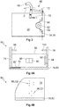
- FIG. 1A is a schematic side view of an embodiment of an inventive device 10 1 for moving charge carriers 12 (see, for example FIG. 9 ).
- the device 10 1 comprises a guide column 14 with a bottom end 15 and a bottom end 17, wherein the guide column 14 is anchored at the bottom end 15 in a bottom plate 16.
- the guide column 14 has a straight, substantially vertical along the in Figure 1A defined z-axis extending first portion 18 and a circular sector-shaped or arcuate second portion 20.
- the provision of the second section 20 is not mandatory.
- the first section 18 comprises a total of three subsections 22, which are identical to one another. Both the subsection 22 of the first section 18 and the annular sector-shaped second section 20 are connected to each other with non-illustrated connecting elements without offset.
- the number of subsections 22 can be chosen freely, so that the height of the guide column 14 can be adjusted accordingly.
- a boom 24 is provided which extends between a housing 26 of the device 10 1 and the annular sector-shaped second portion 20.
- the device 10 1 comprises a carriage 28, which can be moved along the guide column 14.
- the carriage 28 has a number of wheels 30 which roll on the guide column 14, which will be discussed in more detail later.
- a drive device 32 is arranged, with which the carriage 28 along the guide column 14 can be moved. Also on the drive device 32 will be discussed in more detail later.
- the drive device 32 cooperates with a support means 34 running along the guide column 14, which in this case is designed as a chain 36 or as a belt.
- the support means 34 is connected at a first end 38 fixed to the device 10 1 , in the illustrated example in the sector-shaped second section 20 of the guide column 14.
- the support means 34 is of a first guide roller 40 which is fixed to the guide column 14, and a second Deflection pulley 42, which is fixed to the housing 26, deflected. At a second end 44, the support means 34 is secured to the guide post 14 by means of an elastic member 46.
- An adapter 50 1 can be fastened to the carriage 28 by means of a connecting flange 48, which can receive a load carrier 12 (not illustrated here) and can be moved together with the carriage 28 along the guide column 14.
- the housing 26 has a slot-shaped recess (not shown), within which the connection flange 48 can move.
- the connecting flange 48 is shown mounted offset by 90 ° on the carriage 28 about the z-axis, but it is provided that the connecting flange 48 with respect to the Figure 1A is arranged behind or in front of the guide column 14, so that the adapter 50 1 is moved in front of or behind the guide column 14 along this.
- a guide plate 52 is arranged, with which a load not shown here can be guided during emptying from the charge carrier 12.
- the device 10 1 also has a coupling element 54, whose function will be discussed in more detail later.
- the device 10 1 is provided with a housing box 56 in which, for example, not shown electrical and electronic components for controlling the device 10 1 are housed.
- FIG. 1B shown second embodiment of the device 10 2 according to the invention is substantially constructed as the device 10 1 according to the first embodiment.
- a deflecting portion 59 is fixed to the second portion 20, which cooperates with the support means 34 and this leads so that it follows the circular sector-shaped course of the second portion 20.
- a rack 61 is provided in the second section 20, which also follows the circular sector-shaped course of the second section 20 and is formed approximately arcuate. The rack 61 is arranged offset in the y direction to the support means 34.
- the support means 34 extends mostly on the right side of the first section 18 of the guide column 14.
- the second section 20 starting from the first section 18 also to the right. Consequently, the deflecting portion 59 is disposed on the radially inner side of the second portion 20, it being possible to arrange the rack 61 on the radially inner side of the second portion 20 as well FIG. 1B is shown.
- the support means 34 can also largely run on the left side of the guide column 14, so that then the deflection portion 59 is formed so that it leads the support means 34 on the radial outer side of the second portion 20. Accordingly, the rack 61 can extend on the radial outer side of the second section 20.
- the pinion 62 and the further pinion 63 are arranged on a common shaft.
- the rack 61 on the radially outer side and the support means 34 on the radially inner side of the second portion 20 to run or vice versa.
- FIG. 1C A third embodiment of the device according to the invention 10 3, which also, for the most part of the device 10 according to the first embodiment 3 equivalent.
- the support means 34 is designed endlessly, wherein a second deflection roller 65 is arranged at the free end 49 of the guide column 14.
- the device 10 3 comprises the deflection section 59, which deflects the support means 34 in accordance with the course of the second section 20.
- the support means 34 is moved, for which purpose the drive means 32 cooperates with and drives the first deflection roller 42.
- the carriage 28 is fixedly secured to the support means 34 in a suitable manner.
- a rack 61 is not provided.
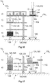
- FIGS. 2A to 2D are different sectional views along the in Figure 1A defined sectional plane AA through the guide column 14 shown. From the FIGS. 2A to 2C it can be seen that the guide column 14 is a half-H-shaped ( FIG. 2A ), an H-shaped ( FIG. 2B ) or a T-shaped ( Figure 2C ) May have cross-section. In addition, from Figures 2A to 2C, the wheels 30 can be seen, with which the carriage 28 rolls on the guide column 14.
- the wheels 30 can be divided into two groups, namely a first group G1 whose wheels 30 have an axis of rotation parallel to the x-axis, and a second group G2 whose wheels 30 have an axis of rotation parallel to the y -Axis run.
- the wheels 30 may be spaced apart from each other with respect to the z-axis.
- the arrangement of the wheels 30 serves to securely transmit the torques occurring during movement of the adapter 50 1 to the guide column 14.
- At least two wheels 30 per group are provided, which roll on opposite sides of the guide column 14.
- a guide column 14 is shown, which has a substantially T-shaped cross-section, which has two rolling surfaces 57, which at a 45 ° angle to the x-axis and the y-axis. On these rolling surfaces 57 roll off the two wheels 30, which belong to a third group G3, whose axes of rotation extend at an angle of 45 ° to the x-axis and the y-axis.
- Both the in FIGS. 2A and 2B illustrated guide columns 14 with a semi-H-shaped and H-shaped cross-section have two mutually parallel legs 58, between which at least one securing portion 60 extends.
- the securing portion 60 is designed as a securing bolt 53.
- the in the FIGS. 2A and 2B carriage, not shown, 28 is designed so that it does not abut the securing bolt 53.
- illustrated guide column 14 with the T-shaped cross section is different from the other cross sections, which in the Figures 2A, 2B and 2D are shown, also in that the guide column has a cavity 55. Also in the Figures 2A, 2B and 2D illustrated cross sections may have a cavity 55 or more cavities 55. In the event that the guide column 14 has one or more cavities 55, the securing portions 60 may also be formed as through holes 73 opening into the cavity 55.
- FIG. 3 is the drive device 32 shown in more detail, with which the carriage 28 along the guide column 14 can be moved.
- the drive device 32 has a pinion 62, which can be rotated by the drive device 32.
- the support means 34 is formed as a chain 36 or a belt, in which or in which the pinion 62 engages positively.
- the chain 36 or the belt deflected by two support means pulleys 64.
- the carriage 28 is raised or lowered along the guide column 14.
- the inventive device 10 1 , 10 2 , 10 3 has a cooperating with the carriage 28 safety device 66.
- the safety device 66 has a securing element 68, which in the in FIG. 3 illustrated embodiment is configured hook-shaped.
- the securing element 68 is rotatably mounted about the y-axis (see. Figures 1A and 1B ) and is biased by a biasing means 70, in the example shown with a spring.
- the spring can be biased, the securing element 68 is connected to a counter-holder 72, which is supported on the chain 36 or on the belt, so that the securing element 68 in the in FIG. 3 shown first position is held.
- the counter-holder 72 can bias the spring 70 only because the chain 36 or the belt is sufficiently tightened and thus can hardly deflect in the direction of action and in the opposite direction of the biasing force provided by the spring 70.
- the securing element 68 is in the first position, the carriage 28 can be moved along the guide column 14. In the event that the chain 36 or the belt breaks, the carriage 28 moves down uncontrollably along the guide column 14. In this case, however, the chain 36 or the belt can be deflected in the effective direction and the opposite direction of the biasing force provided by the spring 70, so that the spring can no longer be biased. Consequently, the securing element 68 is rotated about the y axis in a direction not shown with the arrow P direction in a second position, not shown.
- the securing element 68 in the in figure 2 B engage shown securing bolt 61, so that the carriage 28 is detected on the guide column 14 and no longer can fall uncontrollably along the guide column 14 down.
- a non-illustrated counterweight can be used, which rotates the securing element 68 in the second position in the event that the chain 36 or the belt breaks.
- the securing element 68 can also engage in the through-opening 73.
- FIG. 1C a further embodiment of the safety device 66 is shown.
- a locking toothing 67 is arranged on the guide column 14.
- the fuse element 68 can be biased in the above-mentioned manner in the illustrated in broken lines first position in which the securing element 68 does not engage in the locking teeth 67.
- the carriage 28 can be moved in both directions along the guide column 14. If the support means 34 tears, the securing element 68 is placed in the second position, which is shown by the solid lines. In the second position, the securing element 68 engages in the locking toothing 67 and sets the carriage 28 so tight that it can no longer be moved downwards.
- the device 10 2 , 10 3 a chassis 69, with which the device 10 2 , 10 3 is movable.
- the chassis 69 includes a number of wheels 71, of which at least one is driven by a drive unit not shown in detail.
- the device 10 2 , 10 3 according to the second and third embodiments can be integrated into a driverless transport system.
- the carriage 28 can be moved together with the adapter 50 along the guide column 14. Due to the manner of the embodiment of the support means 34, the carriage 28, the circular sector-shaped second portion 20 of the guide column 14 almost completely through, wherein the carriage 28 and consequently the adapter 50 1 on the path predetermined by the second portion 20 of the guide column 14 around the y -Axis are turned.
- the angle of rotation ⁇ is in Figure 1A marked and there is 150 °. In a corresponding design of the circular sector-shaped second portion 20, it may also be up to 180 °.
- the cargo contained in the charge carrier 12 is poured out in this way gently and directed by the guide plate 52 so that it can be transferred to a receptacle, not shown.
- FIG. 4A is a first embodiment of an adapter according to the invention 50 1 based on a basic front view and in FIG. 4B shown by a schematic side view.
- the adapter 50 1 has a first side wall 74 and a second side wall 76 which are substantially parallel to each other.
- the adapter 50 1 comprises a support section 78 on which at least one charge carrier 12 can be placed.
- the support section 78 is in the first embodiment of the adapter 50 1 as a plate bottom 80 in which a gap 82 is inserted, along which the first side wall 74 can be moved.
- the adapter 50 1 has an adjusting device 84 which, for example, comprises a spindle with which the first side wall 74 can be pushed toward the second side wall 76 and away from it. In this way, the distance between the two side walls 74, 76 can be adapted to the width or the length of the load carrier 12.
- FIG. 4B recognizable, the plate bottom 80 to the front and back with the side walls 74, 76 flush.
- the adapter 50 1 between the side walls 74, 76 extending a rear wall 86, to which a sensor 88 for detecting the presence of a charge carrier 12 in the adapter 50 1 and / or in the immediate vicinity of the adapter 50 1 and a read head 90 to identify and documenting the received charge carriers 12 are attached.
- the rear wall 86 has a slightly lower height than the side walls 74, 76.
- the second side wall 76 has a wall portion 92 which can be biased by a biasing means 94.
- the distance between the first side wall 74 and the wall portion 92 is selected to be slightly less than the length or width of the charge carrier 12.
- the biasing force provided by the biasing means 94 generates a frictional force between the charge carrier 12 and the first side wall 74 and the wall portion 92, so that the charge carrier 12 on the one hand clearly in position with respect to the side walls 74, 76 positioned in the adapter 50 1 and on the other hand held due to the frictional force in the charge carrier 12 and secured against slipping out.
- the adapter 50 1 can be connected to the carriage 28, for which purpose the carriage 28 has the already mentioned connection flange 48.
- FIG. 4B it can be seen that the side walls 74, 76 have a first group Q1 of diamond-shaped through holes 96.
- the through holes 96 of the first group Q1 are used to attach the adapter 50 1 to the connection flange 48 (see. FIG. 1 ).
- a first stop 98 and on the second side wall 76 a second stop 100 is attached.
- the charge carrier 12 is fixed between the plate bottom 80 and the stops 98, 100, so that the charge carrier 12 can not fall out of the adapter 50 1, in particular when the adapter 50 1 along the sector-shaped second portion 20 of Guide column 14 is moved.
- FIG. 5 a second embodiment of the adapter 50 2 according to the invention is shown with reference to a side view.
- the adapter 50 2 according to the second embodiment is largely similar to that of the first embodiment, however, an extension portion 10 2 are connected to the plate bottom 80, whereby even longer charge carriers 12 can be safely accommodated in the adapter 50 2 .
- FIG. 6 a third embodiment of the adapter 50 3 according to the invention is shown with reference to a basic front view.
- the support portion 78 is not formed by a plate bottom 80 but by a first roller 104 disposed on the first side wall 74 and a second roller 106 disposed on the second side wall 76.
- the rollers 104, 106 can be driven by means of a drive unit, not shown, so that a charge carrier 12 can be pulled into the adapter 50 3 and pushed out of it again.
- the rear wall 86 is provided with the joints 82 along which the side walls 74, 76 can be shifted towards and away from each other.
- FIG. 7 a fourth embodiment of the adapter 50 4 according to the invention is shown with reference to a schematic side view.
- the adapter 50 4 according to the fourth embodiment is substantially similar to that of the first embodiment (see FIGS. 4A and 4B ), wherein the plate bottom 80 without extension portion 10 2 projects forward over the side walls 74, 76.
- an extension runner 108 is connected to the first side wall 74 and the second side wall 76 using a second group Q2 of through holes 96, respectively.
- the first stop 98 and the second stop 100 are not attached to the side walls 74, 76, but to the extension runners 108. How out FIG.
- extension runners 108 have two second groups Q2 of the through-holes 96, so that further extension runners 108 can be attached to the extension runners 108 shown.
- the distance between the support portion 78 and the Stops 98, 100 are increased, so that even higher charge carriers 12 in the adapter 50 4 can be added.
- FIG. 8 illustrated fifth embodiment of the adapter 50 5 has a chute 110 for guiding the cargo when emptying the charge carrier 12.
- the rear wall 86 has a greater height than the side walls 74, 76 and therefore projects upwardly beyond the side walls 74, 76.
- the protruding part of the rear wall 86 is part of the pouring device 110.
- the pouring device 110 comprises two guide sections 112, which are movably fastened to the side walls 74, 76 and with which a bulk taper 114 can be adjusted.
- arcuate slots 116 are provided, which are penetrated by fastening means 118. The once set position of the guide portions 112 relative to the rear wall 86 can be fixed with the fastening means 118.
- the adapter 50 5 according to the fifth embodiment, a drip pan 120, with which in particular liquids can be collected.
- liquids may be lubricants or coolants which are used in the manufacture of the cargo and only slowly detach from the load.
- the plate bottom 80 is provided with drain holes 122, so that the liquid discharged from the load can flow into the collecting trough 120.
- the drip pan 120 is quickly detachably connected to the adapter 50 5 so that it can be easily separated from the adapter 50 5 , emptied and connected to the adapter 50 5 again.
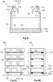
- FIGS. 9A is a first embodiment of a trolley 124 1 according to the invention based on a principal Side view and in FIG. 9B illustrated by a basic front view.
- the transport carriage 124 1 has a carrier device 125 with two first side carriers 126 and two second side carriers 128.
- six first support rollers 132 are fastened to the first side support 126 per floor and six second support rollers 132 are supported on the second side support 128, wherein the number of floors and the number of first and second support rollers 132 can be selected largely freely.
- the transport carriage 124 1 serves to receive the load carrier 12.
- the carrier rollers 132 may be driven by a drive unit, not shown, so that the charge carriers 12 can be placed at one end of a floor on the support rollers 132 and moved within this floor until they themselves in the desired position.
- the first and second carrier rollers 132 are spaced from each other.
- the trolley 124 1 accordingly has no continuous support rollers. At least one of the side supports 126, 128, on the other hand, the side support 126, 128 toward and away from this movable.
- the transport carriage 124 1 guide rods 134, which are arranged so that they do not collide with the charge carriers 12.
- the distance between the side beams 126, 128 is chosen so that it substantially corresponds to the length or the width of the charge carriers 12.
- the side supports 126, 128 guide the charge carriers 12 within the trolley 124 1 and thus ensure an appropriate alignment and security. Even if it suffices for only one of the side supports 126, 128 to be designed to be movable, it is advisable to move the two side supports 126, 128 in synchronism with one another and away from one another. In this way it is ensured that the trolley 124 1 evenly loaded and the risk of tipping over due to a one-sided load is kept low.
- the trolley 124 1 is equipped with wheels 136 so that the trolley 124 1 can be moved by an employee.
- the transport vehicle 124 1 has a track 138, with which the transport vehicle 124 1 without the help of an employee, especially within the factory and thus for internal transport is movable.
- the transport carriage 124 1 comprises a drive unit 140.
- induction loops or the like may be installed in the floor of the workshop to specify the path along which the transport carriage 124 1 is moved.
- FIG. 10 is a second embodiment of the trolley 124 2 2 illustrated by a schematic representation.
- the trolley 124 2 is equipped with a drip pan 142, with which liquids or solids used in the production of the cargoes and only slowly separate from the load, can be collected.
- the transport carriage 124 2 has at least one extension section 144, which is arranged in the illustrated embodiment in the third floor. In this way, the capacity of the trolley 124 2 can be increased. But it is also possible to use the extension section 144 in particular for the support of the charge carrier 12 during the transfer. The transfer of the charge carriers 12 to the transport carriage 124 2 can be simplified due to better accessibility. In this case, the extension portion 144 can be inserted into the side support 126, 128. It can be provided that the extension section 144 between the various levels of the trolley 124 2 is movable.
- the transport carriage 124 2 is equipped with a coupling device 146.
- the trolley 124 2 can be coupled with a coupling partner.
- a coupling partner can, for example, the in Figure 1A shown device 10 1 for moving carriers 12 or a further transport carriage 124, not shown.
- the device 10 1 has the coupling element 54, which can be coupled to the coupling device 146 solely as a result of a corresponding positioning of the transport carriage 124 2 .
- the coupling device 146 and the coupling element 54 may be designed so that the transport carriage 124 2 is fixed in the coupled state in its position and can not roll away.
- an electrically conductive contact between the coupling element 54 and the coupling device 146 can be made in the coupled state, so that electrical energy and electrical signals between the device 10 1 and the trolley 124 2 can be replaced.
- pneumatic, electromagnetic and / or hydraulic connections 152 are integrated in the coupling device 146 and the coupling element 54, so that compressed air and / or hydraulic fluid and / or electrical energy can be transmitted.
- FIGS. 13A and 13B An embodiment of the coupling element 54 and the coupling device 146 is shown in greater detail on the basis of a basic plan view.
- the coupling element 54 is connected to the bottom plate 16 of the device 10 1 and has at a left edge 154 and a right edge 156 in each case two recesses 158, in which two corresponding Projections 160 of the coupling device 146 can be introduced.
- the trolley 124 is clearly positioned and aligned with respect to the device 10 1 .
- an embodiment of the coupling device 146 in which instead of the recesses 158 vertically extending rods are provided, in which corresponding claws of the trolley 124 engage.
- the jaws may be attached at various heights of the trolley 124. A positioning and alignment of the trolley 124 is still possible, as long as the jaws can engage in the rods.
- the transport carriage 124 2 has a number of receiving portions 162.
- a forklift can grab the trolley 124 2 , lift and drive through the workshop.
- the forklifts can drive autonomously themselves, so that in this way the transport carriage 124 2 can be moved automatically without the need for a moving unit 138 or a drive unit 140.
- a 360 ° all-round view for position sensors not shown, arranged on the transport carriage 124 2 can be provided, which is crucial for the smooth operation of driverless transport systems (FTS).
- FTS driverless transport systems
- FIG. 11A and 11B is a third embodiment of the trolley 124 3 according to the invention each shown in a front view.
- the transport carriage 124 3 has a locking device 148, with which the charge carriers 12, which are arranged in the transport carriage 124 3 , can be secured.
- the locking device 148 has a number of locking bars 150, which on the side supports 126, 128 are adjustably mounted.
- the locking device 148 is in an open position, in which the locking bars 150 are vertically aligned, so that the load carriers 12 can be transported from the front or from behind on the trolley 124 3 and removed from this again.
- 11B is the locking device 148 in the locked position in which the locking bars 150 are aligned horizontally so that they secure the carriers 12 in the trolley 124 3 .
- the adjustment of the locking bar 150 between the open position and the locking position can be done by means of a central, not shown lever, so that the adjustment can be done quickly and easily. Alternatively or cumulatively, the adjustment can also take place by means of a motor or actuating cylinder, not shown.
- Also not shown is an embodiment of the trolley 124, in which the locking bars 150 are non-rotatably mounted on the trolley 124, but are movable in the vertical direction. In this embodiment, the locking position corresponds to those in FIG. 11B is shown. To get into the open position, the locking bars 150 are relative to the in FIG.
- 11B selected representation shifted down until they are aligned with the support rollers 132 or as far as positioned under the support rollers 132, so that the charge carriers 12 can be removed from the trolley 124.
- two barrier bars 150 which are arranged on the same floor of the trolley, can be combined to form a continuous barrier bar 150.
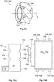
- a wheel 136 designed as a mecanum wheel 164 is shown by means of a perspective view.
- On the circumference of the Mecanum wheel 164 are several, in this case barrel-shaped Rollers 166 arranged at an angle of 45 degrees to the rotational axis T of the entire Mecanum wheel 164 and rotatably mounted on mounting portions 168. Only these wheels 166 make contact with the ground. These rollers 166 have no direct drive and can rotate freely about their oblique bearing axis.
- the transport carriage 124 whether with its own drive or by an employee, can be moved omnidirectionally without the need for a steering device.
- the wheels 136 of the track 138 are designed as mecanum wheels 164.
- the transport carriage 124 2 has a storage rack 170, which is carried out separately from the track unit 138.
- the storage rack 170 includes the side supports 126, 128, the carrier rollers 132 and the collecting trough 142 attached thereto.
- the storage rack 170 can be parked, for example by means of a forklift, not shown, using the receiving portions 162 on the particular autonomously moving trajectory 138.
- the trajectory 138 can therefore be used for various storage shelves 166.
- FIG. 14 A fourth embodiment of the device 10 according to the invention 4 is shown which includes the transport carriage 124 4 according to a fourth embodiment.
- the essential difference from the third exemplary embodiment lies in the design of the coupling device 146.
- the coupling device 146 is not arranged at the bottom of the transport carriage 124 4 . Rather, in each floor of the trolley 124 4 each a group of terminals 152 are arranged, which in each case can be connected to a counterpart 172, which is arranged on the adapter 50 6 , the in figure 15 is shown separately.
- electrical energy, control signals and / or pneumatic or hydraulic fluids between the trolley 124 4 and the adapter can be replaced.
- only one floor of the transport carriage 124 4 is coupled, so that, for example, only the drive units of the support rollers 132 of this floor are supplied with power to drive the respective support rollers 132.
- the supply and removal of the load carrier 12 to or from the trolley 124 4 using the driven carrier rollers 132 is thereby possible without corresponding lines between the floors must be laid.
- FIG. 15 illustrated sixth embodiment of the adapter 50 6 has in relation to FIG. 6 illustrated third embodiment 50 3 the following further difference: While the in FIG. 6 shown adapter 50 3 has the first and the second stop 98, 100, has the in FIG. 15 Adapter 50 6 shown with a continuous retainer rod 175. In this way, even very narrow carriers 12 can be secured against falling out, without the need for the first side wall 74 must be moved to the second side wall 76 as far until that both stops 98, 100 cooperate with the carriers 12 can.
- the provision of the continuous support rod 175 is particularly suitable for adapters 50, which have immovable side walls 74, 76. In the FIG.
- the through-holes 96 can be used to arrange the support rod 175 at different heights on the adapter 506 in order to implement an adaptation to different levels of charge carriers 12 can.
- the through-holes 96 can also be designed as elongated holes, so that a very precise height adjustment is possible.
- All wheels 71, 136 may also be configured as mecanum wheels 164 (cf. FIG. 13B ).
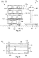
- FIG. 16 is a fifth embodiment of an inventive device 10 5 for guiding charge carriers 12 to a loading and / or unloading station 176 and shown away therefrom on the basis of a basic representation.
- the device 10 1 comprises the transport carriage 124 5 according to a fifth embodiment and a movement device 178 1 according to a first embodiment.
- the structure of the trolley 124 5 largely corresponds to those of the embodiments described above.
- the trolley 124 5 four levels a) to d). In each case four levels a) to d), six first carrier rollers 132 are attached to the first side carriers 126 and six second carrier rollers 132 are attached to the second side carriers 128, respectively.
- the carrier rollers 132 of the levels c) and d) each form a first receiving area 180 1 and the carrier rollers 132 of the levels a) and b) each have a second receiving area 180 2 on which the carrier 12 which is in this case can be stored.
- the carrier rollers 132 can be driven by means of a drive unit, not shown.
- the movement device 178 1 has a lifting column 182, with which a cross member 184 can be raised and lowered.
- the lifting column 182 is supported by a bottom plate 186.
- On the cross member 184 five drivable cross member rollers 188 are fixed in this case, with a different number of cross member rollers 188 can be used.
- the device 10 5 is operated in the following manner:
- the trolley 124 5 is loaded in any position with in this case a total of six load carriers 12, which are stored on the two first receiving areas 180 1 .
- the charge carriers 12 are in a first state, in which they are empty in the illustrated example, that is, do not receive any load G. But they can also be filled with cargo G in the first state.
- the loaded dolly 124 5 is automatically in this case by means of the track 138 in an in FIG. 16 shown transfer position T driven.
- the transfer position T is characterized in that a transfer of the charge carriers 12 from the transport vehicle 124 5 to the movement device 178 1 and vice versa is possible.
- the cross member 184 of the movement device 178 1 is moved by means of the lifting column 182 so that it is aligned with one of the first receiving areas 180 1 . Subsequently, the respective carrier rollers 132 of the transport carriage 124 5 are rotated so that one of the load carriers 12 is moved by the transport carriage 124 5 on the cross member rollers 188, which are also rotated accordingly. In the illustrated case, the second charge carrier 12 has been transferred to the plane c). Subsequently, the cross member 184 is moved to the loading and / or unloading station 176, which is done in this case by lifting the cross member 184. As in FIG.
- the loading and / or unloading station 176 may include, for example, an outlet tube 190, from which the load G can be discharged.
- the charge carrier 12 is moved so close to the loading and / or unloading station 176 that the load G can be safely introduced into the load carrier 12.
- the loading and / or unloading station 176 is set up only for loading the load carriers 12, but not for unloading them.
- the charge carrier 12 After the charge carrier 12 has been completely filled, it is in the second state and is deposited on one of the second receiving sections 180 2 of the transport carriage 124 1 , as shown for the first charge carrier 12, which has been taken from the plane c). This charge carrier 12 has been deposited on the second receiving area 180 2 of the plane a).
- the cross member 184 is lowered accordingly and the cross member rollers 188 and the support rollers 132 is set in a corresponding rotation, so that the charge carrier 12 can be transferred from the cross member 184 to the respective second receiving portion 180 2 .
- the charge carrier 12 has been converted into the second state. Loading and / or unloading of the charge carriers 12 on the first receiving area 180 1 is also possible.
- the charge carriers 12 can also be filled with the load G in the first state.
- the loading and / or unloading station 176 is set up so that it can remove the load G to be processed from the load carriers 12, feed it to a processing machine, not shown, and then reintroduce the processed load G into the load carrier 12.
- the charge carrier 12 is transferred to the second state by filling the processed load G.
- the transport carriage 124 1 can be moved away from the transfer position T, for example to a warehouse where the processed load G is stored or sent. Once the transfer position T has become free, another trolley 124 1 driven to the transfer position T and the above steps are performed again.
- the first receiving portions 180 1 in the levels c) and d) and the second receiving portions 180 2 in the planes a) and b) are arranged.
- 180 1 , 180 2 three charge carriers 12 can be stored per receiving area, so that the trolley 124 1 is loaded with a total of six charge carriers 12.
- the carriers 12 are moved from planes c) and d) to planes a) and b).
- a first receiving area 180 1 are deposited on the charge carrier 12 in the first state, when performing the above steps to a second receiving area 180 2 , are stored on the charge carrier 12 in the second state.
- the dolly 124 1 can be loaded more, which increases the effectiveness of its use.
- FIG. 17 a sixth embodiment of the device 10 6 according to the invention is shown.
- stackable, tray-shaped trays 174 are used.
- the device 10 6 comprises a trolley 124 6 according to a sixth embodiment, which has only the planes a) and b). In the plane b), the first receiving areas 180 1 and in the plane a), the second receiving portions 180 2 are arranged.
- the basic handling of the trays 174 corresponds to that for the in FIG. 16 shown charge carrier 12 has been explained.
- the trays 174 are distributed over several, in this case three stacks.
- the trolley 124 6 is loaded so that the three stacks of empty trays 174 in this case are placed on the first receiving area 180 1 .
- the empty trays 174 are in the first state. If the transport carriage 124 1 is in the transfer position T, one of the stacks is transferred to the movement device 178 2 by a corresponding rotation of the carrier rollers 132 and the crossbar rollers 188.
- the trays 174 have separate receiving spaces, in which usually a single load G is stored. This results in the fact that only the tray 174 of a stack can be loaded, which is not covered by another tray 174 upwards.
- the movement device 178 2 comprises a gripping device 192, with which the trays 174 can be detected and moved from one stack to another stack. Once the top tray 174 of the transferred stack is filled, it is detected by the gripping device 192 and transported from the transferred stack to another stack. Consequently, during the filling of the trays 174, two stacks are provided on the cross member 184. After all trays 174 are filled and thus transferred to the second state, only one stack is left on the cross member 184, which has exclusively filled trays 174. This stack is deposited on the second receiving area 180 2 of the transport carriage 124 6 .
- the gripping device 192 may lift only the upper three trays 174, for example. Subsequently, the stack is moved with the lower seven trays 174 by a corresponding rotation of the cross member rollers 188 so that the top Tray 174 of the stack for the loading and unloading station 176 is accessible. The top of the seven trays 174 is then loaded and unloaded. The stack is then moved back to the starting position and the remaining upper three trays 174 of the gripping device 192 again stored. In this case, there is only one stack on the cross member 184 since the gripper 192 lifts the top three trays 174 until the stack with the seven bottom trays 174 has returned to the home position. If necessary, the upper three trays 174 of the gripping device 192 can be temporarily stored on the cross member 184. Thus, each tray 174 can be loaded and unloaded regardless of the stacking order.
- the trays 174 may be loaded in the first state with load G, which is removed from the receiving spaces for processing and then stored there again. The trays 174 are then transferred to the second state when they are filled exclusively with the processed load G.
Landscapes
- Engineering & Computer Science (AREA)
- Mechanical Engineering (AREA)
- Transportation (AREA)
- Structural Engineering (AREA)
- Civil Engineering (AREA)
- Life Sciences & Earth Sciences (AREA)
- Geology (AREA)
- Warehouses Or Storage Devices (AREA)
Applications Claiming Priority (2)
| Application Number | Priority Date | Filing Date | Title |
|---|---|---|---|
| DE202018102002.1U DE202018102002U1 (de) | 2018-04-12 | 2018-04-12 | Vorrichtung zum Zuführen von Ladungsträgern und/oder Trays zu einer Be- und/oder Entladestation und von dieser weg |
| DE202018102001.3U DE202018102001U1 (de) | 2018-04-12 | 2018-04-12 | Vorrichtung zum Bewegen von Ladungsträgern, Adapter zum Aufnehmen von Ladungsträgern sowie Transportwagen zum Aufnehmen und Transportieren von Ladungsträgern |
Publications (2)
| Publication Number | Publication Date |
|---|---|
| EP3552998A2 true EP3552998A2 (fr) | 2019-10-16 |
| EP3552998A3 EP3552998A3 (fr) | 2019-12-25 |
Family
ID=66105246
Family Applications (1)
| Application Number | Title | Priority Date | Filing Date |
|---|---|---|---|
| EP19168741.7A Pending EP3552998A3 (fr) | 2018-04-12 | 2019-04-11 | Dispositif de déplacement de supports de chargement, adaptateur de réception des supports de chargement ainsi que chariot de transport permettant de recevoir et de transporter des supports de chargement |
Country Status (1)
| Country | Link |
|---|---|
| EP (1) | EP3552998A3 (fr) |
Cited By (4)
| Publication number | Priority date | Publication date | Assignee | Title |
|---|---|---|---|---|
| CN116969178A (zh) * | 2023-06-30 | 2023-10-31 | 山东辰禾智能装备有限公司 | 一种塑料型材焊接前物料输送码放装置及方法 |
| CN118323889A (zh) * | 2024-06-11 | 2024-07-12 | 湖南特瓷新材料有限公司 | 一种管道的搬运设备 |
| DE102023208695A1 (de) | 2023-09-08 | 2025-03-13 | Robert Bosch Gesellschaft mit beschränkter Haftung | Transportvorrichtung zum Transportieren und Übergeben eines Transportgutes |
| DE102023208698A1 (de) | 2023-09-08 | 2025-03-13 | Robert Bosch Gesellschaft mit beschränkter Haftung | Transportvorrichtung zum Transportieren und Übergeben eines Transportgutes |
Family Cites Families (4)
| Publication number | Priority date | Publication date | Assignee | Title |
|---|---|---|---|---|
| FR2652529B1 (fr) * | 1989-10-02 | 1992-02-07 | Vega Automation | Robot. |
| JP2001247294A (ja) * | 1999-12-27 | 2001-09-11 | Sugiyasu Kogyo Kk | 搬送装置 |
| JP2009107739A (ja) * | 2007-10-26 | 2009-05-21 | Hitachi Plant Technologies Ltd | 昇降装置における昇降体吊垂支持用チェーンの切断検知装置 |
| FI124214B (fi) * | 2012-06-15 | 2014-05-15 | Rpv Lift Oy | Laite astian tyhjentämiseksi |
-
2019
- 2019-04-11 EP EP19168741.7A patent/EP3552998A3/fr active Pending
Cited By (4)
| Publication number | Priority date | Publication date | Assignee | Title |
|---|---|---|---|---|
| CN116969178A (zh) * | 2023-06-30 | 2023-10-31 | 山东辰禾智能装备有限公司 | 一种塑料型材焊接前物料输送码放装置及方法 |
| DE102023208695A1 (de) | 2023-09-08 | 2025-03-13 | Robert Bosch Gesellschaft mit beschränkter Haftung | Transportvorrichtung zum Transportieren und Übergeben eines Transportgutes |
| DE102023208698A1 (de) | 2023-09-08 | 2025-03-13 | Robert Bosch Gesellschaft mit beschränkter Haftung | Transportvorrichtung zum Transportieren und Übergeben eines Transportgutes |
| CN118323889A (zh) * | 2024-06-11 | 2024-07-12 | 湖南特瓷新材料有限公司 | 一种管道的搬运设备 |
Also Published As
| Publication number | Publication date |
|---|---|
| EP3552998A3 (fr) | 2019-12-25 |
Similar Documents
| Publication | Publication Date | Title |
|---|---|---|
| EP3497043B1 (fr) | Système de chargement pour la palettisation de produits mélangés sur une palette cible | |
| EP3183190B1 (fr) | Systèmes de stockage et/ou de triage | |
| DE4213542C2 (de) | Regalanordnung | |
| AT510516B1 (de) | Fertigungszelle mit einer werkteil- transfereinrichtung und transporteinrichtung für werkteile und teileträger | |
| EP2013123B1 (fr) | Module de préparation pour des palettes comprenant un module de transport qui peut être déplacé en-dessous des emplacements d'empilement des palettes, avec un dispositif de levage | |
| EP2870092B1 (fr) | Dispositif pour empiler des articles en plusieurs couches sur un support | |
| EP3272697B1 (fr) | Appareil d'utilisation d'étagère pour un système de stockage de palettes | |
| EP2539248A1 (fr) | Dispositif de suspension de charge pour un appareil de commande pour rayonnages, appareil de commande pour rayonnages et système de stockage | |
| EP3552998A2 (fr) | Dispositif de déplacement de supports de chargement, adaptateur de réception des supports de chargement ainsi que chariot de transport permettant de recevoir et de transporter des supports de chargement | |
| EP2485969B1 (fr) | Magasin de stockage à navettes, station de navettes et procédé pour faire fonctionner le magasin | |
| WO2018224185A1 (fr) | Véhicule logistique et base d'un véhicule logistique | |
| DE102006039697B4 (de) | Vorrichtung und Verfahren zum Entladen von mit Palettenlagen beladenen Tablaren | |
| WO2017144055A1 (fr) | Entraînement télescopique, transtockeur comportant celui-ci et procédé de fonctionnement ainsi qu'utilisation associés | |
| WO2010135756A1 (fr) | Dispositif de préparation de commandes | |
| DE102014003451A1 (de) | Reagalbediengerät mit hochgesetzter Fahrschiene | |
| EP3418227B1 (fr) | Robot transporteur sur rail et procédé de fonctionnement d'un robot transporteur sur rail | |
| EP1446353A1 (fr) | Dispositif servant a deplacer un moyen de suspension de charge en sens transversal dans un systeme en hauteur destine a manipuler des unites de stockage | |
| DE202018102002U1 (de) | Vorrichtung zum Zuführen von Ladungsträgern und/oder Trays zu einer Be- und/oder Entladestation und von dieser weg | |
| EP1975074B1 (fr) | Dispositif et procédé de chargement et de déchargement d'une multitude d'objets installés dans un récipient de réception ouvert sur le dessus | |
| DE4203823C2 (de) | Lagereinrichtung | |
| DE102021122406B4 (de) | Stapelvorrichtung, Automationsmodul, Fertigungssystem sowie Verfahren zur Beschickung einer Werkzeugmaschine | |
| DE60000747T2 (de) | Ladestation mit Schleuse | |
| DE202018102001U1 (de) | Vorrichtung zum Bewegen von Ladungsträgern, Adapter zum Aufnehmen von Ladungsträgern sowie Transportwagen zum Aufnehmen und Transportieren von Ladungsträgern | |
| EP0352785A1 (fr) | Dispositif de manipulation et de stockage des palettes et des objets similaires à palettes ou autres | |
| EP0798238B1 (fr) | Système d'entreposage pour palettes pour objets longs |
Legal Events
| Date | Code | Title | Description |
|---|---|---|---|
| PUAI | Public reference made under article 153(3) epc to a published international application that has entered the european phase |
Free format text: ORIGINAL CODE: 0009012 |
|
| STAA | Information on the status of an ep patent application or granted ep patent |
Free format text: STATUS: THE APPLICATION HAS BEEN PUBLISHED |
|
| AK | Designated contracting states |
Kind code of ref document: A2 Designated state(s): AL AT BE BG CH CY CZ DE DK EE ES FI FR GB GR HR HU IE IS IT LI LT LU LV MC MK MT NL NO PL PT RO RS SE SI SK SM TR |
|
| AX | Request for extension of the european patent |
Extension state: BA ME |
|
| PUAL | Search report despatched |
Free format text: ORIGINAL CODE: 0009013 |
|
| AK | Designated contracting states |
Kind code of ref document: A3 Designated state(s): AL AT BE BG CH CY CZ DE DK EE ES FI FR GB GR HR HU IE IS IT LI LT LU LV MC MK MT NL NO PL PT RO RS SE SI SK SM TR |
|
| AX | Request for extension of the european patent |
Extension state: BA ME |
|
| RIC1 | Information provided on ipc code assigned before grant |
Ipc: B65G 65/00 20060101AFI20191121BHEP Ipc: B66F 9/08 20060101ALI20191121BHEP Ipc: B65G 65/23 20060101ALI20191121BHEP |
|
| STAA | Information on the status of an ep patent application or granted ep patent |
Free format text: STATUS: REQUEST FOR EXAMINATION WAS MADE |
|
| 17P | Request for examination filed |
Effective date: 20200103 |
|
| RBV | Designated contracting states (corrected) |
Designated state(s): AL AT BE BG CH CY CZ DE DK EE ES FI FR GB GR HR HU IE IS IT LI LT LU LV MC MK MT NL NO PL PT RO RS SE SI SK SM TR |
|
| STAA | Information on the status of an ep patent application or granted ep patent |
Free format text: STATUS: EXAMINATION IS IN PROGRESS |
|
| 17Q | First examination report despatched |
Effective date: 20220530 |
|
| RAP1 | Party data changed (applicant data changed or rights of an application transferred) |
Owner name: SEMOTEC GMBH |