EP3552947A1 - Antriebsmodul und surfvorrichtung damit - Google Patents
Antriebsmodul und surfvorrichtung damit Download PDFInfo
- Publication number
- EP3552947A1 EP3552947A1 EP19168436.4A EP19168436A EP3552947A1 EP 3552947 A1 EP3552947 A1 EP 3552947A1 EP 19168436 A EP19168436 A EP 19168436A EP 3552947 A1 EP3552947 A1 EP 3552947A1
- Authority
- EP
- European Patent Office
- Prior art keywords
- sealed chamber
- module
- rotating device
- propelling
- transmission shaft
- Prior art date
- Legal status (The legal status is an assumption and is not a legal conclusion. Google has not performed a legal analysis and makes no representation as to the accuracy of the status listed.)
- Granted
Links
Images
Classifications
-
- B—PERFORMING OPERATIONS; TRANSPORTING
- B63—SHIPS OR OTHER WATERBORNE VESSELS; RELATED EQUIPMENT
- B63B—SHIPS OR OTHER WATERBORNE VESSELS; EQUIPMENT FOR SHIPPING
- B63B32/00—Water sports boards; Accessories therefor
- B63B32/10—Motor-propelled water sports boards
-
- B—PERFORMING OPERATIONS; TRANSPORTING
- B63—SHIPS OR OTHER WATERBORNE VESSELS; RELATED EQUIPMENT
- B63B—SHIPS OR OTHER WATERBORNE VESSELS; EQUIPMENT FOR SHIPPING
- B63B32/00—Water sports boards; Accessories therefor
-
- B—PERFORMING OPERATIONS; TRANSPORTING
- B63—SHIPS OR OTHER WATERBORNE VESSELS; RELATED EQUIPMENT
- B63H—MARINE PROPULSION OR STEERING
- B63H21/00—Use of propulsion power plant or units on vessels
- B63H21/12—Use of propulsion power plant or units on vessels the vessels being motor-driven
- B63H21/17—Use of propulsion power plant or units on vessels the vessels being motor-driven by electric motor
-
- B—PERFORMING OPERATIONS; TRANSPORTING
- B63—SHIPS OR OTHER WATERBORNE VESSELS; RELATED EQUIPMENT
- B63H—MARINE PROPULSION OR STEERING
- B63H5/00—Arrangements on vessels of propulsion elements directly acting on water
- B63H5/07—Arrangements on vessels of propulsion elements directly acting on water of propellers
-
- B—PERFORMING OPERATIONS; TRANSPORTING
- B63—SHIPS OR OTHER WATERBORNE VESSELS; RELATED EQUIPMENT
- B63H—MARINE PROPULSION OR STEERING
- B63H11/00—Marine propulsion by water jets
- B63H11/02—Marine propulsion by water jets the propulsive medium being ambient water
- B63H11/04—Marine propulsion by water jets the propulsive medium being ambient water by means of pumps
- B63H11/08—Marine propulsion by water jets the propulsive medium being ambient water by means of pumps of rotary type
- B63H2011/081—Marine propulsion by water jets the propulsive medium being ambient water by means of pumps of rotary type with axial flow, i.e. the axis of rotation being parallel to the flow direction
Definitions
- the present disclosure relates to the technical field of water sports, and in particular, relates to a propelling module and a surfing apparatus having the same.
- Surfing sports are well populated among people because of adventure and benefits to health.
- Common surfboards may be used only under assistance of the pushing force of wind waves. When there is not wind wave or the wind wave is tiny, the surfboards may not be well used.
- surfers may surf as they desire even when there is no wind wave or the wind wave is tiny.
- the electric surfboard has the advantages of good mobility, flexibility, environmental-friendliness and the like, and thus surfing has become a water leisure and entertainment sport welcomed among people.
- An electric surfboard mainly includes a surfboard body, a power-supplying battery, a motor, a control device and a main tailpiece; wherein the power-supplying battery, the motor and a part of the control device all need to be mounted in a hollow chamber of the surfboard body, thus, the lines in the hollow chamber are very complicated and easily damageable. Consequently, the electric surfboard is damaged generally due to the problem of the motor and the control device in the hollow chamber, in addition, the motor and the control device in the hollow chamber need to be repaired by professionals with skills. As such, users have to transport the entire surfboards to the manufacturers for repair. After having repaired the surfboards, the manufacturers need to transport the entire electric surfboards back to the users. The electric surfboard has a very large size, and thus the repair and transportation are complicated, and the transportation cost is high.
- the present disclosure provides a propelling module and a surfing apparatus having the same.
- a propelling module includes: a module housing, a rotating device, a transmission shaft and a propeller; wherein the module housing is provided with a sealed chamber, the propeller is arranged outside the sealed chamber, the rotating device is arranged inside the sealed chamber, one end of the transmission shaft is connected to the rotating device, the other end of the transmission shaft penetrates through a side wall of the sealed chamber and extends to the exterior of the sealed chamber, and the other end of the transmission shaft is connected to the propeller;
- the module housing is provided with a power connection member, the rotating device is electrically connected to the power connection member, and the rotating device is configured to be electrically connected to an external device via the power connection member;
- the two ends of the module housing are respectively provided with a storage end and a tail end, the sealed chamber is arranged at the storage end, the module housing is further provided with a water passage, wherein the water passage penetrates through from a bottom surface of the tail end to a side surface of the tail end, and the propeller is arranged in the water passage.
- the rotating device is arranged in the sealed chamber, which effectively prevents external water and impurities from contacting the rotating device, and improves the safety and reliability of the rotating device.
- the rotating device is conveniently connected to the external device via the power connection member, which is simple and causes no damages, and greatly reduces the maintenance workload.
- the propelling force may be effectively increased, the propelling speed of the propelling module is improved, and the effect of energy saving is achieved.
- the rotating device is electrically connected to an external battery module via the power connection member.
- the rotating device is connected to the external battery module via the power connection member.
- the external battery module is capable of conveniently supplying power to the rotating device.
- the power connection member comprises a connection tube and a connection joint; wherein the connection tube upwardly extends from a top surface at a top portion of the module housing along a vertical direction and the connection tube is in communication with the sealed chamber, the connection joint is sealingly connected in the connection tube and the rotating device is electrically connected to the connection joint, and the connection joint is electrically connected to the external battery module.
- connection tube upwardly protrudes along the vertical direction, such that the power connection member and the external battery module are connected in an insertion manner, which facilitates the connection and improves the connection precision.
- connection joint and the connection tube are sealingly connected, which effectively prevents the external water and impurities from entering the sealed chamber.
- the power connection member is conveniently connected to the battery module via the connection joint.
- the rotating device includes a control assembly and a motor; wherein the control assembly includes a brushless motor controller, an input of the brushless motor controller is electrically connected to the power connection member, an output of the brushless motor controller is electrically connected to the motor, and the transmission shaft is connected to a rotor of the motor.
- the control assembly includes a brushless motor controller, an input of the brushless motor controller is electrically connected to the power connection member, an output of the brushless motor controller is electrically connected to the motor, and the transmission shaft is connected to a rotor of the motor.
- an external direct current flows through the power connection member to the input of the brushless motor controller, and the direct current is converted into an alternating current. Afterwards, the alternating current flows through the output of the brushless motor controller to the motor, such that the motor operates.
- the transmission shaft is driven to rotate by means of the rotor of the motor.
- the operation is reliable, and the use and control are convenient.
- control assembly further includes a governor
- module housing is further provided with a control connection member; wherein an input of the governor is electrically connected to an external control device via the control connection member, and an output of the governor is electrically connected to the motor.
- the governor is connected to the external control device in a wired manner, and the control connection portion facilitates the connection. In this way, no damage is caused, and the maintenance workload is greatly reduced. Meanwhile, the governor has a high speed adjustment efficiency and a wide speed governor range.
- control assembly further includes a governor; wherein an input of the governor is provided with a signal receiving unit, the signal receiving unit being configured to receive an instruction signal sent by an external control device, and an output of the governor is electrically connected to the motor.
- the governor is connected to the external control device in a wireless manner, which is convenient, flexible and easy to control. Meanwhile, the governor has a high speed adjustment efficiency and a wide speed governor range.
- control assembly is connected to a top portion of the sealed chamber, and the control assembly is arranged above the transmission shaft.
- the control assembly is arranged above the transmission shaft, such that a small space is occupied.
- the propelling module is small in size and easy to transport, thereby greatly reducing transport and repair costs.
- the module housing includes an upper cover and a lower housing; wherein the upper cover is connected to a top surface of the lower housing, the sealed chamber is defined between the upper cover and the lower housing, and a sealer ring is arranged between the upper cover and the lower housing.
- the upper cover and the lower housing facilitate loading and unloading of the rotating device in the sealed chamber.
- the sealing ring effectively enhances the sealing performance between the upper cover and the lower housing.
- the motor is connected to the interior of the housing, the control assembly is connected to the upper cover, and the control assembly and the motor are connected via a line joint.
- the line joint facilitates connection between the control assembly and the motor, and facilitates loading and unloading of the propelling module, thereby improving the repair efficiency.
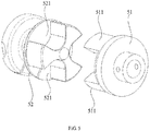
- a coupling is arranged between the rotating device and the transmission shaft, the coupling including a first rotating shaft and a second rotating shaft having the same rotation axial line; wherein one side of the first rotating shaft is connected to the transmission shaft and the other side of the first rotating shaft is provided with at least one protrusion, one side of the second rotating shaft is connected to the rotating device and the other side of the second rotating shaft is arranged to be opposite to the other side of the first rotating shaft, and the other side of the second rotating shaft is provided with at least one groove, the protrusion being inserted into the groove.
- the coupling effectively enhances mounting precision between the rotating device and the transmission shaft, and facilitates mounting of the transmission shaft.
- an elastic member is pressed between an outer side wall of the protrusion and an inner side wall of the groove.
- the elastic member achieves the effects of buffering and shock absorption.
- the module housing is further provided with a water inlet and a water outlet, wherein the water inlet and the water outlet are both in communication with the sealed chamber;
- the propelling module further comprises a cooling tube, wherein one end of the cooling tube is connected to the tail end and is in communication with the water passage, the cooling tube passes through the water inlet and penetrates through the rotating device, and the other end of the cooling tube passes through the water outlet and is arranged outside the sealed chamber;
- module housing is further provided with a tube groove, and the cooling tube is arranged in the tube groove.
- a surfing apparatus is further provided.
- the surfing apparatus includes: a surfboard, a battery module and a propelling module as described above; wherein the battery module is connected to the surfboard, and the propelling module is detachably connected to the surfboard.
- the propelling module is detachably connected, such that when the propelling module is to be repaired, the propelling module only needs to be transported to the manufacturer.
- the propelling module is small in structure, and is easy to transport, thereby greatly reduces the transportation and repair costs.
- the rotating device is arranged in the sealed chamber, such that safety and reliability of the rotating device are improved.
- the rotating device is conveniently connected to an external device via the power connection member, which is simple and causes no damages.
- the propelling module is small in size and easy to transport, thereby greatly reducing transport and repair costs.
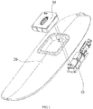
- a surfing apparatus includes a propelling module 10, a surfboard 20 and a battery module 30; wherein the battery module 30 is connected to the surfboard 20, and the propelling module 10 is detachably connected to the surfboard 20. Since the propelling module 10 is detachably connected to the surfboard 20, even if the propelling module 10 fails, the propelling module 10 may still be detached from the surfboard 20 and mailed or transported to the manufacturer for repair. The entire structure of the propelling module 10 is far smaller than the structure of the surfboard 20, such that mailing or transportation of the propelling module 10 is convenient, and the repair cost is greatly lowered.
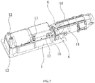
- the propelling module 10 includes a module housing 1, a rotating device 2, a transmission shaft 3 and a propeller 4; wherein the module housing 1 has a sealed chamber 11, the propeller 4 is arranged outside the sealed chamber 11, the rotating device 2 is arranged inside the sealed chamber 11, one end of the transmission shaft 3 is connected to the rotating device 2, the other end of the transmission shaft 3 passes through a side wall of the sealed chamber 11 and extends to the exterior of the sealed chamber 11, and the other end of the transmission shaft 3 is connected to the propeller 4.
- the transmission shaft 3 is capable of rotating and driving the propeller 4 to rotate.
- the propelling module 10 is propelled and moves.
- the rotating device 2 is arranged inside the sealed chamber 11, which effectively prevents external water and impurities from being in contact with the rotating device 2, and improves safety and reliability of the rotating device 2.
- the module housing 1 is provided with a power connection member 12, the rotating device 2 is electrically connected to the power connection member 12, and the rotating device 2 is electrically connected to an external device via the power connection member 12.
- the rotating device 2 is conveniently connected to an external device via the power connection member 12, which is simple and causes no damages, and greatly reduces the maintenance workload.
- the rotating device 2 may be electrically connected to the battery module 30 via the power connection member 12.
- the rotating device 2 is connected to the external battery module 30 via the power connection member 12, such that the external battery module 30 supplies power to the rotating device 2, and the rotating device 2 converts the electrical energy into mechanical energy and drives the transmission shaft 3 to rotate.
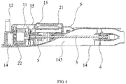
- Two ends of the module housing 1 are respectively provided with a storage end 141 and a tail end 142, the sealed chamber 11 is arranged at the storage end 141, the module housing 1 may be provided with a water passage 143, wherein the water passage 143 penetrates through from a bottom surface of the tail end 142 to a side surface of the tail end 142, and the propeller 4 is arranged in the water passage 143.
- the propeller 4 By arranging the propeller 4 in the water passage 143, the propelling force may be effectively increased, the propelling speed of the propelling module 10 is improved, and the effect of energy saving is achieved.
- the power connection member 12 may include a connection tube 121 and a connection joint 122; wherein the connection tube 121 upwardly extends from a top surface at a top portion of the module housing 1 along a vertical direction and the connection tube 121 is in communication with the sealed chamber 11.
- the connection tube 121 upwardly protrudes along the vertical direction, such that the power connection member 12 and the external battery module 30 are connected in an insertion manner, which facilitates the connection and improves the connection precision.
- connection joint 122 is sealingly connected to the connection tube 121, the rotating device 2 is electrically connected to the connection joint 122, and the connection joint 122 is electrically connected to the external battery module 30.
- the connection joint 122 and the connection tube 121 are sealingly connected, which effectively prevents the external water and impurities from entering the sealed chamber. Meanwhile, by virtue of the connection joint, the power connection member 122 is conveniently connected to the battery module 30 via the connection joint.
- the connection joint 122 is sealingly connected inside the connection tube 121 by means of glue feeding.
- Two power connection members 12 may be used, and the two connection joints 122 may include a copper male joint and a copper female joint; wherein the copper male joint and the copper female joint may be respectively configured to be connected to a live wire and a neutral wire of the battery module 30.
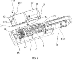
- the rotating device 2 may include a control assembly 21 and a motor 22; wherein the control assembly 21 may include a brushless motor controller, wherein an input of the brushless motor controller is electrically connected to the power connection member 12, and an output of the brushless motor controller is electrically connected to the motor 22.
- the battery module 30 generally supplies direct current, whereas the motor 22 needs alternating current to operate. Therefore, the direct current of the battery module 30 flows to the input of the brushless motor controller through the power connection member 12, and is converted into the alternating current via the brushless motor controller. Afterwards, the alternating current flows inside the motor 22 through the output of the brushless motor controller, such that by means of the brushless motor controller, the motor 22 is capable of operating.
- the transmission shaft 3 may be connected to the rotor of the motor 22.
- the transmission shaft 3 is driven to rotate by means of the rotor of the motor 22.
- the operation is reliable, and the use and control are convenient.
- the control assembly 21 may further include a governor, wherein the governor may be connected to an external control device (not shown in the drawings) in a wired manner or a wireless manner.
- the module housing 1 may be provided with a control connection member 13; wherein an input of the governor is electrically connected to the control device arranged outside the sealed chamber 11 via the control connection member 13, and an output of the governor is electrically connected to the motor 22.
- the control device arranged outside the sealed chamber 11 sends an instruction signal, wherein the instruction signal is transmitted to the input of the governor via the connection control member 13.
- the governor is capable of controlling the motor 22 and controlling power of the motor 22 via the output of the governor, such that the rotation speed of the rotor of the motor 22 is controlled.
- the governor is connected to the control device arranged outside the sealed chamber 11 in a wired manner, and the connection is facilitated via the control connection member 13, which is simple and causes no damages, and greatly reduces the maintenance workload. Meanwhile, the governor has a high speed adjustment efficiency and a wide speed governor range.
- the input of the governor may be provided with a signal receiving unit (not shown in the drawings), wherein the signal receiving unit is configured to receive the instruction signal sent by the control device arranged outside the sealed chamber 11; and the output of the governor is electrically connected to the motor 22.
- the control device arranged outside the sealed chamber 11 may send the instruction signal via a signal transmitting unit, wherein the instruction signal is transmitted to the governor via the signal receiving unit.
- the governor is capable of controlling the motor 22 and controlling power of the motor 22 via the output of the governor, such that the rotation speed of the rotor of the motor 22 is controlled. In this way, the propelling speed of the propelling module 10 is controlled.
- the governor is connected to the external control device in a wireless manner, which is convenient, flexible and easy to control. Meanwhile, the governor has a high speed adjustment efficiency and a wide speed governor range.
- the control assembly 21 may be connected to a top portion of the sealed chamber 11. This effectively enhances the connection strength between structures inside the sealed chamber 11.
- the control assembly 21 is connected to the module housing 1 via a fastening screw.
- the control assembly 21 may be arranged above the transmission shaft 3. In this way, in the sealed chamber 11, the motor 22 is arranged on a left end portion and the transmission shaft 3 is arranged on a right end portion.
- the control assembly 21 is arranged above the transmission shaft 3, such that the control assembly 21 occupies a small space, and thus the internal structure of the sealed chamber 11 is compact and reasonable. As such, the entire structure of the propelling module 10 is small, which is easy to transport and greatly reduces transportation and repair costs.
- the module housing 1 may include an upper cover 15 and a lower housing 14, wherein the upper cover 15 is connected to a top surface of the lower housing 14.
- the upper cover 15 and the lower housing 14 may be connected via a bolt.
- the sealed chamber 14 is defined between the upper cover 15 and the lower housing 14, and a sealing ring is pressed between the upper cover 14 and the lower housing 14. The sealing ring effectively enhances the sealing performance between the upper cover 15 and the lower housing 14.
- the motor 22 may be connected to the lower housing 14, and the control assembly 21 may be connected to the upper cover 15.
- the sealed chamber 11 has a reasonable internal deployment.
- the control assembly 21 and the motor 22 may be connected via a line joint (not shown in the drawings). By virtue of the line joint, connection between the control assembly 21 and the motor 22 may be conveniently controlled, and removing of the propelling module 10 is facilitated, thereby improving the repair efficiency.
- the module housing 1 may be provided with a water inlet 16 and a water outlet 17, wherein the water inlet 16 and the water outlet 17 are both in communication with the sealed chamber 11.
- the propelling module 10 may further include a cooling tube 6, wherein one end of the cooling tube 6 is connected to the tail end 142 and in communication with the water passage 143, the cooling tube 6 passes through the water inlet 16 and penetrates through the rotating device 2, and the other end of the cooling tube 6 passes through the water outlet 17 and is arranged outside the sealed chamber 11.
- the water flow in the water passage 143 enters the cooling tube 6 via one end of the cooling tube 6.
- the cooling tube 6 penetrates through the water inlet 16 such that a portion of the cooling tube 6 is arranged inside the sealed chamber 11.
- the cooling tube 6 heat energy inside the sealed chamber 11 may be effectively removed, thereby lowering the temperature.
- the cooling tube 6 penetrates through the control assembly 21 and the motor 22 of the rotating device 2, thereby achieving a better heat dissipation effect.
- the cooling tube 6 penetrates through the water outlet 17, such that the water inside the cooling tube 6 is discharged to the outside of the sealed chamber 11.
- the module housing 1 may be provided with a tube groove 18, wherein the cooling tube is arranged in the tube groove 18.
- the connection strength between the module housing 1 and the cooling tube 6 is enhanced, and positional shift and backlash of the cooling tube are prevented during use.
- the water inlet of the cooling tube 6 connected to the tail end 142 is arranged behind the propeller 4, that is, the propeller 4 is arranged between the water inlet of the cooling tube 6 and the transmission shaft 3.
- a coupling 5 may be arranged between the rotating device 2 and the transmission shaft 3, wherein the coupling 5 has a first rotating shaft 51 and a second rotating shaft 52 having the same rotation axial line.
- One side of the first rotating shaft 51 is connected to the transmission shaft 3, and the other side of the first rotating shaft 51 is provided with at least one protrusion 511.
- One side of the second rotating shaft 52 is connected to the rotating device 2, and the other side of the second rotating shaft 52 is arranged to be opposite to the other side of the first rotating shaft 51, and the other side of the second rotating shaft 52 is provided with at least one groove 521, the protrusion 511 inserted into the groove 521.
- An elastic member (not shown in the drawings) may be pressed between an outer side wall of the protrusion 511 and an inner side wall of the groove 521. After the protrusion 511 is inserted into the groove 521, a gap is present between the outer side wall of the protrusion 511 and the inner side wall of the groove 521. By pressing an elastic member at the gap, the first rotating shaft 51 and the second rotating shaft 52 are subject to an elastic force.
- the elastic member achieves the effects of buffering and shock-absorption, protects the propelling module 10, and thus prolongs the life time of the propelling module 10.
- the elastic member may be made from rubber.
Landscapes
- Chemical & Material Sciences (AREA)
- Engineering & Computer Science (AREA)
- Combustion & Propulsion (AREA)
- Mechanical Engineering (AREA)
- Ocean & Marine Engineering (AREA)
- Connection Of Motors, Electrical Generators, Mechanical Devices, And The Like (AREA)
- Oxygen, Ozone, And Oxides In General (AREA)
Applications Claiming Priority (1)
| Application Number | Priority Date | Filing Date | Title |
|---|---|---|---|
| CN201810316266.5A CN110356524A (zh) | 2018-04-10 | 2018-04-10 | 推进模块及包含其的冲浪设备 |
Publications (2)
| Publication Number | Publication Date |
|---|---|
| EP3552947A1 true EP3552947A1 (de) | 2019-10-16 |
| EP3552947B1 EP3552947B1 (de) | 2022-03-09 |
Family
ID=66105068
Family Applications (1)
| Application Number | Title | Priority Date | Filing Date |
|---|---|---|---|
| EP19168436.4A Active EP3552947B1 (de) | 2018-04-10 | 2019-04-10 | Antriebsmodul und surfvorrichtung damit |
Country Status (4)
| Country | Link |
|---|---|
| US (1) | US10953957B2 (de) |
| EP (1) | EP3552947B1 (de) |
| CN (1) | CN110356524A (de) |
| ES (1) | ES2909423T3 (de) |
Cited By (6)
| Publication number | Priority date | Publication date | Assignee | Title |
|---|---|---|---|---|
| WO2019129687A1 (en) | 2017-12-27 | 2019-07-04 | Ride Awake Ab | Electric motorised watercraft and driveline system |
| US10940917B2 (en) | 2016-09-12 | 2021-03-09 | Kai Concepts, LLC | Watercraft device with hydrofoil and electric propeller system |
| EP3822158A1 (de) * | 2019-11-14 | 2021-05-19 | Jetwake Co., Ltd | Elektrische surfbrett |
| US11608144B2 (en) | 2020-01-03 | 2023-03-21 | Ride Awake Ab | Motorized watercraft |
| USD995678S1 (en) | 2020-01-03 | 2023-08-15 | Ride Awake Ab | Electronically propelled surfboard |
| US12246811B2 (en) | 2020-04-22 | 2025-03-11 | Kai Concepts, LLC | Watercraft device with a handheld controller |
Families Citing this family (10)
| Publication number | Priority date | Publication date | Assignee | Title |
|---|---|---|---|---|
| CN110356524A (zh) | 2018-04-10 | 2019-10-22 | 优机国际有限公司 | 推进模块及包含其的冲浪设备 |
| FR3101609B1 (fr) * | 2019-10-02 | 2022-05-13 | Motion Concept Group | Embarcation, telle qu’une planche de surf ou de paddle, à assistance électrique |
| CN110844006A (zh) * | 2019-11-12 | 2020-02-28 | 深圳市苇渡智能科技有限公司 | 一种模块式水上运动装置 |
| CN110911888A (zh) * | 2019-11-12 | 2020-03-24 | 深圳市苇渡智能科技有限公司 | 一种防水接头与水上运动装置 |
| US11097812B2 (en) * | 2019-11-13 | 2021-08-24 | Jetwake Co., Ltd | Electric surfboard |
| CN111874163B (zh) * | 2020-08-25 | 2024-10-18 | 深圳市苇渡智能科技有限公司 | 电动冲浪板 |
| CN111874165B (zh) * | 2020-08-25 | 2024-10-18 | 深圳市苇渡智能科技有限公司 | 电动冲浪板 |
| US12479540B2 (en) * | 2022-04-20 | 2025-11-25 | HC Bros, LLC | Multifunctional stand-up paddleboard and methods |
| US20230391423A1 (en) * | 2022-06-07 | 2023-12-07 | Fresh Consulting, Inc | Motorized watercraft |
| WO2024227054A1 (en) * | 2023-04-27 | 2024-10-31 | Garner Development Services, Llc | Jet pump propulsion system |
Citations (5)
| Publication number | Priority date | Publication date | Assignee | Title |
|---|---|---|---|---|
| EP1977968A1 (de) * | 2007-04-05 | 2008-10-08 | Joy Ride Technology Co., Ltd. | Propellergetriebene Vorrichtung zum Wellenreiten |
| WO2011100654A2 (en) * | 2010-02-13 | 2011-08-18 | Dainuri Rott | Electric powered surfboard propulsion and control systems |
| WO2016099406A1 (en) * | 2014-12-15 | 2016-06-23 | 3S Sport D.O.O. | An inflatable watercraft with an embedded drive |
| CN205675195U (zh) * | 2016-05-18 | 2016-11-09 | 陈朝忠 | 一种冲浪板 |
| DE202017107820U1 (de) * | 2017-12-21 | 2018-01-12 | Lampuga Gmbh | Aufblasbares Surfboard mit Antriebseinheit |
Family Cites Families (40)
| Publication number | Priority date | Publication date | Assignee | Title |
|---|---|---|---|---|
| US3536025A (en) | 1968-08-21 | 1970-10-27 | Leisure Ind | Motorized surfboard |
| JPH0730812B2 (ja) | 1987-01-28 | 1995-04-10 | 三信工業株式会社 | 動力伝達装置 |
| US4811682A (en) * | 1988-02-26 | 1989-03-14 | Hwang Chi Y | Mini inflatable yacht |
| JP2509471Y2 (ja) | 1988-07-19 | 1996-09-04 | モレックス インコーポレーテッド | 防水型電気コネクタ |
| US5017166A (en) | 1990-07-30 | 1991-05-21 | Chang Pao Yuan | Power-driven surfboard |
| JPH06171583A (ja) * | 1992-12-10 | 1994-06-21 | Hitachi Ltd | 水上走行する板状の乗物または海上用救命具 |
| DE4430775A1 (de) | 1994-08-30 | 1996-03-07 | Grote & Hartmann | Dichtungsvorrichtung für mehrpolige elektrische Steckverbinder |
| US5595497A (en) | 1995-03-01 | 1997-01-21 | Tescorp Seismic Products, Inc. | Underwater electrical connector |
| JPH08239090A (ja) * | 1995-03-07 | 1996-09-17 | Mitsubishi Heavy Ind Ltd | 水中ビークル |
| US20010042498A1 (en) * | 2000-01-10 | 2001-11-22 | Burnham Daniel J. | Drive and control system for watercraft |
| JP2002193185A (ja) * | 2000-10-18 | 2002-07-10 | Yamaha Motor Co Ltd | エンジン付サーフボード |
| US6409560B1 (en) * | 2001-04-12 | 2002-06-25 | Shawn M. Austin | Motorized surfboard device |
| CN2529053Y (zh) * | 2001-11-16 | 2003-01-01 | 邓和平 | 电动阀门执行器用自充气防水密封装置 |
| DE202004010920U1 (de) | 2004-07-12 | 2004-11-18 | Ktr Kupplungstechnik Gmbh | Zahn, Zahnkranz und Doppelzahnelement zur Verwendung in einer Kupplung |
| US6966808B1 (en) * | 2004-07-30 | 2005-11-22 | Chung-D Liao | Power surfboard |
| US20070283865A1 (en) | 2004-11-01 | 2007-12-13 | Bouncing Brain Innovations Season Two Subsidiary 14, Llc | Powered surfboard for preserving energy of surfer during paddling |
| CN201010038Y (zh) * | 2007-02-12 | 2008-01-23 | 六逸科技股份有限公司 | 水中推进器 |
| US7930985B2 (en) * | 2008-01-02 | 2011-04-26 | Walworth Christopher J | Sports board |
| EP2588367A1 (de) * | 2010-07-01 | 2013-05-08 | Boomerboard LLC | Motorisiertes wasserfahrzeugsystem mit austauschbarem motormodul |
| AU2012254885A1 (en) | 2011-11-16 | 2013-05-30 | Paul Martin | Electrically powered surfboard |
| US9718521B2 (en) | 2012-11-14 | 2017-08-01 | Steven John Derrah | Drive-N-glide surfboard (jet drive) |
| DE202013012451U1 (de) | 2013-09-18 | 2016-11-17 | Markus Schilcher | Surfboard mit Antrieb |
| CN204124333U (zh) * | 2014-09-03 | 2015-01-28 | 徐荣 | 一种电动冲浪板 |
| WO2016061274A1 (en) | 2014-10-15 | 2016-04-21 | Boomerboard, Llc | Electric motor for watercraft |
| DE102015108863A1 (de) | 2015-06-03 | 2016-12-08 | Sashay Gmbh | Wassersportgerät |
| KR101758290B1 (ko) | 2015-10-22 | 2017-07-14 | 이중건 | 워트제트에 의해 추진되는 모듈타입의 서퍼 보드 |
| CN205418042U (zh) * | 2016-03-14 | 2016-08-03 | 李旺利 | 一种动力冲浪板 |
| KR101767476B1 (ko) | 2016-03-30 | 2017-08-11 | 이중건 | 워트제트에 의해 추진되는 모듈타입의 서퍼 보드 |
| CN205738032U (zh) | 2016-05-12 | 2016-11-30 | 浙江道丰进出口有限公司 | 一种水上动力滑板冷却系统 |
| JP6349345B2 (ja) | 2016-05-20 | 2018-06-27 | 矢崎総業株式会社 | プラグコネクタ及び電源回路遮断装置 |
| WO2017220000A1 (zh) * | 2016-06-24 | 2017-12-28 | 洛唯优 | 划水模块装置 |
| CN206494089U (zh) | 2017-02-17 | 2017-09-15 | 陈朝忠 | 一种冲浪板 |
| CN207129115U (zh) | 2017-05-26 | 2018-03-23 | 东莞市特浪新能源科技有限公司 | 轻型电动冲浪板 |
| CN108061105B (zh) | 2017-11-09 | 2020-06-05 | 湖北恒力传动机械股份有限公司 | 一种梅花联轴器 |
| CN207670632U (zh) | 2017-11-15 | 2018-07-31 | 广西特飞云天航空动力科技有限公司 | 充气动力型应急救生装置 |
| DE202017107824U1 (de) | 2017-12-21 | 2018-01-12 | Lampuga Gmbh | Surfboard mit Jetantrieb |
| CN116215822B (zh) | 2017-12-27 | 2025-12-16 | 赖德艾威克有限公司 | 电动机动水路航行器和传动系系统 |
| KR102211891B1 (ko) | 2018-01-19 | 2021-02-03 | 라딘 악티에볼라그 | 전기적으로 동력을 공급받는, 워터-제트 추진식 서프보드 |
| CN110356524A (zh) | 2018-04-10 | 2019-10-22 | 优机国际有限公司 | 推进模块及包含其的冲浪设备 |
| CN208484799U (zh) | 2018-05-14 | 2019-02-12 | 田瑜 | 冲浪设备 |
-
2018
- 2018-04-10 CN CN201810316266.5A patent/CN110356524A/zh active Pending
- 2018-07-11 US US16/033,077 patent/US10953957B2/en active Active
-
2019
- 2019-04-10 ES ES19168436T patent/ES2909423T3/es active Active
- 2019-04-10 EP EP19168436.4A patent/EP3552947B1/de active Active
Patent Citations (5)
| Publication number | Priority date | Publication date | Assignee | Title |
|---|---|---|---|---|
| EP1977968A1 (de) * | 2007-04-05 | 2008-10-08 | Joy Ride Technology Co., Ltd. | Propellergetriebene Vorrichtung zum Wellenreiten |
| WO2011100654A2 (en) * | 2010-02-13 | 2011-08-18 | Dainuri Rott | Electric powered surfboard propulsion and control systems |
| WO2016099406A1 (en) * | 2014-12-15 | 2016-06-23 | 3S Sport D.O.O. | An inflatable watercraft with an embedded drive |
| CN205675195U (zh) * | 2016-05-18 | 2016-11-09 | 陈朝忠 | 一种冲浪板 |
| DE202017107820U1 (de) * | 2017-12-21 | 2018-01-12 | Lampuga Gmbh | Aufblasbares Surfboard mit Antriebseinheit |
Cited By (13)
| Publication number | Priority date | Publication date | Assignee | Title |
|---|---|---|---|---|
| US11919608B2 (en) | 2016-09-12 | 2024-03-05 | Kai Concepts, LLC | Watercraft device with hydrofoil and electric propeller system |
| US10940917B2 (en) | 2016-09-12 | 2021-03-09 | Kai Concepts, LLC | Watercraft device with hydrofoil and electric propeller system |
| US11479324B2 (en) | 2016-09-12 | 2022-10-25 | Kai Concepts, LLP | Watercraft device with hydrofoil and electric propeller system |
| US12103643B2 (en) | 2016-09-12 | 2024-10-01 | Kai Concepts, LLC | Watercraft device with hydrofoil and electric propeller system |
| US12122481B2 (en) | 2016-09-12 | 2024-10-22 | Kai Concepts, LLC | Wireless handheld controller for use with a watercraft device |
| EP3732098B1 (de) | 2017-12-27 | 2023-08-02 | Ride Awake AB | Elektrisches motorwasserfahrzeug und antriebssystem |
| US11780538B2 (en) | 2017-12-27 | 2023-10-10 | Ride Awake Ab | Electric motorised watercraft and driveline system |
| WO2019129687A1 (en) | 2017-12-27 | 2019-07-04 | Ride Awake Ab | Electric motorised watercraft and driveline system |
| EP3822158A1 (de) * | 2019-11-14 | 2021-05-19 | Jetwake Co., Ltd | Elektrische surfbrett |
| EP4234393A3 (de) * | 2019-11-14 | 2023-09-27 | Jetwake Co., Ltd | Elektrische surfbrett |
| US11608144B2 (en) | 2020-01-03 | 2023-03-21 | Ride Awake Ab | Motorized watercraft |
| USD995678S1 (en) | 2020-01-03 | 2023-08-15 | Ride Awake Ab | Electronically propelled surfboard |
| US12246811B2 (en) | 2020-04-22 | 2025-03-11 | Kai Concepts, LLC | Watercraft device with a handheld controller |
Also Published As
| Publication number | Publication date |
|---|---|
| CN110356524A (zh) | 2019-10-22 |
| US20190308696A1 (en) | 2019-10-10 |
| ES2909423T3 (es) | 2022-05-06 |
| EP3552947B1 (de) | 2022-03-09 |
| US10953957B2 (en) | 2021-03-23 |
Similar Documents
| Publication | Publication Date | Title |
|---|---|---|
| US10953957B2 (en) | Propelling module and surfing apparatus having the same | |
| CN109895964B (zh) | 推进模块、冷却系统和冲浪设备 | |
| CN207157465U (zh) | 一种整体式水下机器人 | |
| CN108327875B (zh) | 一种低耗能潜水器 | |
| CN108791791A (zh) | 一种遥控电动船外机推进器 | |
| FR2823177B1 (fr) | Systeme de refrigeration pour le propulseur immerge de navire, externe a la coque | |
| GB2624555A8 (en) | Outboard electric motor | |
| PL1792826T3 (pl) | Środki łożyskujące jednostkę napędzającą i system napędzający dla statków wodnych | |
| CN210364284U (zh) | 水翼冲浪板 | |
| CN107444593B (zh) | 一种紧凑型高推动比水下机器人 | |
| CN110304219A (zh) | 水下推进器及水下组合推进器 | |
| CN210912843U (zh) | 一种电动喷水推进器 | |
| CN213109748U (zh) | 用于水中的推进器 | |
| CN112046719B (zh) | 用于水中的推进器 | |
| KR101110685B1 (ko) | 거주구와 조향추진체가 선수에 구비된 선박 | |
| CN217260595U (zh) | 一种用于无人船的新型浮筒 | |
| CN207157470U (zh) | 一种小型水下推进器 | |
| CN105539847B (zh) | 一种水空两栖无人机 | |
| CN109733566A (zh) | 一种水下助推器 | |
| CN207809742U (zh) | 具有分离式驱动器的水下设备 | |
| CN110588921B (zh) | 一种浮球装置以及水下机器人 | |
| CN112591062A (zh) | 应用于水下无人航行器的负浮力补偿装置 | |
| CN221718775U (zh) | 一种无触点蛙人助推器 | |
| CN222801944U (zh) | 一种便携式大功率电动鱼鳍电池防水结构 | |
| CN206485542U (zh) | 水下智能推进器 |
Legal Events
| Date | Code | Title | Description |
|---|---|---|---|
| PUAI | Public reference made under article 153(3) epc to a published international application that has entered the european phase |
Free format text: ORIGINAL CODE: 0009012 |
|
| STAA | Information on the status of an ep patent application or granted ep patent |
Free format text: STATUS: REQUEST FOR EXAMINATION WAS MADE |
|
| 17P | Request for examination filed |
Effective date: 20190523 |
|
| AK | Designated contracting states |
Kind code of ref document: A1 Designated state(s): AL AT BE BG CH CY CZ DE DK EE ES FI FR GB GR HR HU IE IS IT LI LT LU LV MC MK MT NL NO PL PT RO RS SE SI SK SM TR |
|
| AX | Request for extension of the european patent |
Extension state: BA ME |
|
| RAP1 | Party data changed (applicant data changed or rights of an application transferred) |
Owner name: YUJET INTERNATIONAL CORPORATION LIMITED |
|
| RIN1 | Information on inventor provided before grant (corrected) |
Inventor name: TIAN, YU |
|
| STAA | Information on the status of an ep patent application or granted ep patent |
Free format text: STATUS: EXAMINATION IS IN PROGRESS |
|
| 17Q | First examination report despatched |
Effective date: 20201110 |
|
| REG | Reference to a national code |
Ref country code: DE Ref legal event code: R079 Ref document number: 602019012262 Country of ref document: DE Free format text: PREVIOUS MAIN CLASS: B63B0035790000 Ipc: B63B0032100000 |
|
| RIC1 | Information provided on ipc code assigned before grant |
Ipc: B63H 21/17 20060101ALI20210719BHEP Ipc: B63H 11/08 20060101ALI20210719BHEP Ipc: B63B 32/10 20200101AFI20210719BHEP |
|
| GRAP | Despatch of communication of intention to grant a patent |
Free format text: ORIGINAL CODE: EPIDOSNIGR1 |
|
| STAA | Information on the status of an ep patent application or granted ep patent |
Free format text: STATUS: GRANT OF PATENT IS INTENDED |
|
| INTG | Intention to grant announced |
Effective date: 20210921 |
|
| GRAS | Grant fee paid |
Free format text: ORIGINAL CODE: EPIDOSNIGR3 |
|
| GRAA | (expected) grant |
Free format text: ORIGINAL CODE: 0009210 |
|
| STAA | Information on the status of an ep patent application or granted ep patent |
Free format text: STATUS: THE PATENT HAS BEEN GRANTED |
|
| AK | Designated contracting states |
Kind code of ref document: B1 Designated state(s): AL AT BE BG CH CY CZ DE DK EE ES FI FR GB GR HR HU IE IS IT LI LT LU LV MC MK MT NL NO PL PT RO RS SE SI SK SM TR |
|
| REG | Reference to a national code |
Ref country code: CH Ref legal event code: EP Ref country code: AT Ref legal event code: REF Ref document number: 1473945 Country of ref document: AT Kind code of ref document: T Effective date: 20220315 |
|
| REG | Reference to a national code |
Ref country code: IE Ref legal event code: FG4D |
|
| REG | Reference to a national code |
Ref country code: DE Ref legal event code: R096 Ref document number: 602019012262 Country of ref document: DE |
|
| REG | Reference to a national code |
Ref country code: ES Ref legal event code: FG2A Ref document number: 2909423 Country of ref document: ES Kind code of ref document: T3 Effective date: 20220506 |
|
| REG | Reference to a national code |
Ref country code: LT Ref legal event code: MG9D |
|
| REG | Reference to a national code |
Ref country code: NL Ref legal event code: MP Effective date: 20220309 |
|
| PG25 | Lapsed in a contracting state [announced via postgrant information from national office to epo] |
Ref country code: SE Free format text: LAPSE BECAUSE OF FAILURE TO SUBMIT A TRANSLATION OF THE DESCRIPTION OR TO PAY THE FEE WITHIN THE PRESCRIBED TIME-LIMIT Effective date: 20220309 Ref country code: RS Free format text: LAPSE BECAUSE OF FAILURE TO SUBMIT A TRANSLATION OF THE DESCRIPTION OR TO PAY THE FEE WITHIN THE PRESCRIBED TIME-LIMIT Effective date: 20220309 Ref country code: NO Free format text: LAPSE BECAUSE OF FAILURE TO SUBMIT A TRANSLATION OF THE DESCRIPTION OR TO PAY THE FEE WITHIN THE PRESCRIBED TIME-LIMIT Effective date: 20220609 Ref country code: LT Free format text: LAPSE BECAUSE OF FAILURE TO SUBMIT A TRANSLATION OF THE DESCRIPTION OR TO PAY THE FEE WITHIN THE PRESCRIBED TIME-LIMIT Effective date: 20220309 Ref country code: HR Free format text: LAPSE BECAUSE OF FAILURE TO SUBMIT A TRANSLATION OF THE DESCRIPTION OR TO PAY THE FEE WITHIN THE PRESCRIBED TIME-LIMIT Effective date: 20220309 Ref country code: BG Free format text: LAPSE BECAUSE OF FAILURE TO SUBMIT A TRANSLATION OF THE DESCRIPTION OR TO PAY THE FEE WITHIN THE PRESCRIBED TIME-LIMIT Effective date: 20220609 |
|
| REG | Reference to a national code |
Ref country code: AT Ref legal event code: MK05 Ref document number: 1473945 Country of ref document: AT Kind code of ref document: T Effective date: 20220309 |
|
| PG25 | Lapsed in a contracting state [announced via postgrant information from national office to epo] |
Ref country code: LV Free format text: LAPSE BECAUSE OF FAILURE TO SUBMIT A TRANSLATION OF THE DESCRIPTION OR TO PAY THE FEE WITHIN THE PRESCRIBED TIME-LIMIT Effective date: 20220309 Ref country code: GR Free format text: LAPSE BECAUSE OF FAILURE TO SUBMIT A TRANSLATION OF THE DESCRIPTION OR TO PAY THE FEE WITHIN THE PRESCRIBED TIME-LIMIT Effective date: 20220610 Ref country code: FI Free format text: LAPSE BECAUSE OF FAILURE TO SUBMIT A TRANSLATION OF THE DESCRIPTION OR TO PAY THE FEE WITHIN THE PRESCRIBED TIME-LIMIT Effective date: 20220309 |
|
| PG25 | Lapsed in a contracting state [announced via postgrant information from national office to epo] |
Ref country code: NL Free format text: LAPSE BECAUSE OF FAILURE TO SUBMIT A TRANSLATION OF THE DESCRIPTION OR TO PAY THE FEE WITHIN THE PRESCRIBED TIME-LIMIT Effective date: 20220309 |
|
| PG25 | Lapsed in a contracting state [announced via postgrant information from national office to epo] |
Ref country code: SM Free format text: LAPSE BECAUSE OF FAILURE TO SUBMIT A TRANSLATION OF THE DESCRIPTION OR TO PAY THE FEE WITHIN THE PRESCRIBED TIME-LIMIT Effective date: 20220309 Ref country code: SK Free format text: LAPSE BECAUSE OF FAILURE TO SUBMIT A TRANSLATION OF THE DESCRIPTION OR TO PAY THE FEE WITHIN THE PRESCRIBED TIME-LIMIT Effective date: 20220309 Ref country code: RO Free format text: LAPSE BECAUSE OF FAILURE TO SUBMIT A TRANSLATION OF THE DESCRIPTION OR TO PAY THE FEE WITHIN THE PRESCRIBED TIME-LIMIT Effective date: 20220309 Ref country code: PT Free format text: LAPSE BECAUSE OF FAILURE TO SUBMIT A TRANSLATION OF THE DESCRIPTION OR TO PAY THE FEE WITHIN THE PRESCRIBED TIME-LIMIT Effective date: 20220711 Ref country code: EE Free format text: LAPSE BECAUSE OF FAILURE TO SUBMIT A TRANSLATION OF THE DESCRIPTION OR TO PAY THE FEE WITHIN THE PRESCRIBED TIME-LIMIT Effective date: 20220309 Ref country code: CZ Free format text: LAPSE BECAUSE OF FAILURE TO SUBMIT A TRANSLATION OF THE DESCRIPTION OR TO PAY THE FEE WITHIN THE PRESCRIBED TIME-LIMIT Effective date: 20220309 Ref country code: AT Free format text: LAPSE BECAUSE OF FAILURE TO SUBMIT A TRANSLATION OF THE DESCRIPTION OR TO PAY THE FEE WITHIN THE PRESCRIBED TIME-LIMIT Effective date: 20220309 |
|
| REG | Reference to a national code |
Ref country code: DE Ref legal event code: R026 Ref document number: 602019012262 Country of ref document: DE |
|
| PG25 | Lapsed in a contracting state [announced via postgrant information from national office to epo] |
Ref country code: PL Free format text: LAPSE BECAUSE OF FAILURE TO SUBMIT A TRANSLATION OF THE DESCRIPTION OR TO PAY THE FEE WITHIN THE PRESCRIBED TIME-LIMIT Effective date: 20220309 Ref country code: IS Free format text: LAPSE BECAUSE OF FAILURE TO SUBMIT A TRANSLATION OF THE DESCRIPTION OR TO PAY THE FEE WITHIN THE PRESCRIBED TIME-LIMIT Effective date: 20220709 Ref country code: AL Free format text: LAPSE BECAUSE OF FAILURE TO SUBMIT A TRANSLATION OF THE DESCRIPTION OR TO PAY THE FEE WITHIN THE PRESCRIBED TIME-LIMIT Effective date: 20220309 |
|
| REG | Reference to a national code |
Ref country code: CH Ref legal event code: PL |
|
| PLBI | Opposition filed |
Free format text: ORIGINAL CODE: 0009260 |
|
| PLBI | Opposition filed |
Free format text: ORIGINAL CODE: 0009260 |
|
| PLAX | Notice of opposition and request to file observation + time limit sent |
Free format text: ORIGINAL CODE: EPIDOSNOBS2 |
|
| 26 | Opposition filed |
Opponent name: WBV WEISENBURGER BAU+VERWALTUNG GMBH Effective date: 20221125 |
|
| REG | Reference to a national code |
Ref country code: BE Ref legal event code: MM Effective date: 20220430 |
|
| 26 | Opposition filed |
Opponent name: RADINN AB Effective date: 20221209 |
|
| PG25 | Lapsed in a contracting state [announced via postgrant information from national office to epo] |
Ref country code: MC Free format text: LAPSE BECAUSE OF FAILURE TO SUBMIT A TRANSLATION OF THE DESCRIPTION OR TO PAY THE FEE WITHIN THE PRESCRIBED TIME-LIMIT Effective date: 20220309 Ref country code: LU Free format text: LAPSE BECAUSE OF NON-PAYMENT OF DUE FEES Effective date: 20220410 Ref country code: LI Free format text: LAPSE BECAUSE OF NON-PAYMENT OF DUE FEES Effective date: 20220430 Ref country code: DK Free format text: LAPSE BECAUSE OF FAILURE TO SUBMIT A TRANSLATION OF THE DESCRIPTION OR TO PAY THE FEE WITHIN THE PRESCRIBED TIME-LIMIT Effective date: 20220309 Ref country code: CH Free format text: LAPSE BECAUSE OF NON-PAYMENT OF DUE FEES Effective date: 20220430 |
|
| PG25 | Lapsed in a contracting state [announced via postgrant information from national office to epo] |
Ref country code: SI Free format text: LAPSE BECAUSE OF FAILURE TO SUBMIT A TRANSLATION OF THE DESCRIPTION OR TO PAY THE FEE WITHIN THE PRESCRIBED TIME-LIMIT Effective date: 20220309 Ref country code: BE Free format text: LAPSE BECAUSE OF NON-PAYMENT OF DUE FEES Effective date: 20220430 |
|
| PG25 | Lapsed in a contracting state [announced via postgrant information from national office to epo] |
Ref country code: IE Free format text: LAPSE BECAUSE OF NON-PAYMENT OF DUE FEES Effective date: 20220410 |
|
| PLBB | Reply of patent proprietor to notice(s) of opposition received |
Free format text: ORIGINAL CODE: EPIDOSNOBS3 |
|
| P01 | Opt-out of the competence of the unified patent court (upc) registered |
Effective date: 20230811 |
|
| PLAB | Opposition data, opponent's data or that of the opponent's representative modified |
Free format text: ORIGINAL CODE: 0009299OPPO |
|
| R26 | Opposition filed (corrected) |
Opponent name: RADINN AB Effective date: 20221209 |
|
| PG25 | Lapsed in a contracting state [announced via postgrant information from national office to epo] |
Ref country code: HU Free format text: LAPSE BECAUSE OF FAILURE TO SUBMIT A TRANSLATION OF THE DESCRIPTION OR TO PAY THE FEE WITHIN THE PRESCRIBED TIME-LIMIT; INVALID AB INITIO Effective date: 20190410 |
|
| PG25 | Lapsed in a contracting state [announced via postgrant information from national office to epo] |
Ref country code: MK Free format text: LAPSE BECAUSE OF FAILURE TO SUBMIT A TRANSLATION OF THE DESCRIPTION OR TO PAY THE FEE WITHIN THE PRESCRIBED TIME-LIMIT Effective date: 20220309 Ref country code: CY Free format text: LAPSE BECAUSE OF FAILURE TO SUBMIT A TRANSLATION OF THE DESCRIPTION OR TO PAY THE FEE WITHIN THE PRESCRIBED TIME-LIMIT Effective date: 20220309 |
|
| APBP | Date of receipt of notice of appeal recorded |
Free format text: ORIGINAL CODE: EPIDOSNNOA2O |
|
| APAW | Appeal reference deleted |
Free format text: ORIGINAL CODE: EPIDOSDREFNO |
|
| APAH | Appeal reference modified |
Free format text: ORIGINAL CODE: EPIDOSCREFNO |
|
| APAW | Appeal reference deleted |
Free format text: ORIGINAL CODE: EPIDOSDREFNO |
|
| APBM | Appeal reference recorded |
Free format text: ORIGINAL CODE: EPIDOSNREFNO |
|
| APBP | Date of receipt of notice of appeal recorded |
Free format text: ORIGINAL CODE: EPIDOSNNOA2O |
|
| PG25 | Lapsed in a contracting state [announced via postgrant information from national office to epo] |
Ref country code: MT Free format text: LAPSE BECAUSE OF FAILURE TO SUBMIT A TRANSLATION OF THE DESCRIPTION OR TO PAY THE FEE WITHIN THE PRESCRIBED TIME-LIMIT Effective date: 20220309 |
|
| APBQ | Date of receipt of statement of grounds of appeal recorded |
Free format text: ORIGINAL CODE: EPIDOSNNOA3O |
|
| APBQ | Date of receipt of statement of grounds of appeal recorded |
Free format text: ORIGINAL CODE: EPIDOSNNOA3O |
|
| PGFP | Annual fee paid to national office [announced via postgrant information from national office to epo] |
Ref country code: DE Payment date: 20250430 Year of fee payment: 7 |
|
| PGFP | Annual fee paid to national office [announced via postgrant information from national office to epo] |
Ref country code: GB Payment date: 20250423 Year of fee payment: 7 Ref country code: ES Payment date: 20250519 Year of fee payment: 7 |
|
| PGFP | Annual fee paid to national office [announced via postgrant information from national office to epo] |
Ref country code: IT Payment date: 20250430 Year of fee payment: 7 |
|
| PGFP | Annual fee paid to national office [announced via postgrant information from national office to epo] |
Ref country code: FR Payment date: 20250424 Year of fee payment: 7 |
|
| PG25 | Lapsed in a contracting state [announced via postgrant information from national office to epo] |
Ref country code: TR Free format text: LAPSE BECAUSE OF FAILURE TO SUBMIT A TRANSLATION OF THE DESCRIPTION OR TO PAY THE FEE WITHIN THE PRESCRIBED TIME-LIMIT Effective date: 20220309 |