EP3552885A1 - Verbundkomponente für ein kraftfahrzeug - Google Patents
Verbundkomponente für ein kraftfahrzeug Download PDFInfo
- Publication number
- EP3552885A1 EP3552885A1 EP19168040.4A EP19168040A EP3552885A1 EP 3552885 A1 EP3552885 A1 EP 3552885A1 EP 19168040 A EP19168040 A EP 19168040A EP 3552885 A1 EP3552885 A1 EP 3552885A1
- Authority
- EP
- European Patent Office
- Prior art keywords
- positioning
- support body
- tongue
- opening portion
- opening
- Prior art date
- Legal status (The legal status is an assumption and is not a legal conclusion. Google has not performed a legal analysis and makes no representation as to the accuracy of the status listed.)
- Granted
Links
Images

Classifications
-
- B—PERFORMING OPERATIONS; TRANSPORTING
- B60—VEHICLES IN GENERAL
- B60R—VEHICLES, VEHICLE FITTINGS, OR VEHICLE PARTS, NOT OTHERWISE PROVIDED FOR
- B60R13/00—Elements for body-finishing, identifying, or decorating; Arrangements or adaptations for advertising purposes
- B60R13/02—Internal Trim mouldings ; Internal Ledges; Wall liners for passenger compartments; Roof liners
- B60R13/0206—Arrangements of fasteners and clips specially adapted for attaching inner vehicle liners or mouldings
-
- F—MECHANICAL ENGINEERING; LIGHTING; HEATING; WEAPONS; BLASTING
- F16—ENGINEERING ELEMENTS AND UNITS; GENERAL MEASURES FOR PRODUCING AND MAINTAINING EFFECTIVE FUNCTIONING OF MACHINES OR INSTALLATIONS; THERMAL INSULATION IN GENERAL
- F16B—DEVICES FOR FASTENING OR SECURING CONSTRUCTIONAL ELEMENTS OR MACHINE PARTS TOGETHER, e.g. NAILS, BOLTS, CIRCLIPS, CLAMPS, CLIPS OR WEDGES; JOINTS OR JOINTING
- F16B5/00—Joining sheets or plates, e.g. panels, to one another or to strips or bars parallel to them
- F16B5/06—Joining sheets or plates, e.g. panels, to one another or to strips or bars parallel to them by means of clamps or clips
- F16B5/0607—Joining sheets or plates, e.g. panels, to one another or to strips or bars parallel to them by means of clamps or clips joining sheets or plates to each other
- F16B5/0621—Joining sheets or plates, e.g. panels, to one another or to strips or bars parallel to them by means of clamps or clips joining sheets or plates to each other in parallel relationship
- F16B5/0664—Joining sheets or plates, e.g. panels, to one another or to strips or bars parallel to them by means of clamps or clips joining sheets or plates to each other in parallel relationship at least one of the sheets or plates having integrally formed or integrally connected snap-in-features
Definitions
- the present invention relates to a composite component for a motor vehicle.
- Cladding elements formed as composite components are often used in motor vehicles such as, for example, a spar deck, a side spoiler, a rear spoiler, a bumper, a grille or parts of them.
- the composite components are usually manufactured in a shell-like structure, having an outer shell usually painted in the color of the body, and a support body which is connected to the outer shell and which allows fixing, using fasteners, the composite component thus obtained to a vehicle part.
- a side spoiler for a motor vehicle having a spoiler element forming the outer profile and a support member arranged on the inner face and can be connected to the spoiler element.
- the spoiler element has, along its longitudinal sides, a first lateral edge and a second lateral edge opposite it, wherein the first lateral edge is formed at least in part by a fold which forms a counterpane with the inner face, and wherein the second side edge is formed by a flange projecting from the inner face.
- the support member extends, in the connected state, at least in part from the first lateral edge to the second lateral edge, in which the support element is then connected to the first lateral edge by complementarity of shapes with at least one bearing area on the underside, and the support member is also connected to the second side edge through at least one snap connection.
- the snap-in connection is formed by a snap-in element which protrudes from the flange and forms a channel with the inner face, and through a complementary snap-on element formed on the support member and received in the channel. The spoiler element and the support element can thus be inserted by insertion into one assembly direction.
- the latching elements inherently have a certain amount of play and tolerance in these elements, so that it is also possible to achieve a slight shift of the spoiler element, but all the same visually or tactilely noticeable, even in the case of properly snap-fitting of the spoiler element and the supporting element, in particular when a force is applied, such as for example exerted by an application by hand, which is unsatisfactory, especially for high-end motor vehicles.
- connection between the support member and the spoiler element is only at the edges whereas, for example, there is no connection in the center of the elements so that that, for example for reasons of temperature variations and therefore different expansions that go together between the support member and the spoiler element, an annoying rattling may occur.
- the document DE 10 2017 007 530 A1 proposes a composite component for a vehicle, comprising an outer envelope and a support body held in the outer envelope by complementarity of shapes, wherein the support body has an elastic foam.
- the foam of the support body is resiliently supported against the outer casing, effectively preventing rattling of the support body in the outer casing.
- composite members disclosed herein also disclose the problems resulting from bonding only at the edges of the outer shell and the support body, as well as the need for a neat bond.
- a stylistic element to a body part and fix it in three orthogonal directions X, Y and Z, this stylistic element comprising first and second elements which respectively form an attachment in the X direction to fix the style element on the body part.
- the first element cooperates with a first locking aperture in the Z direction, the second element with a second locking aperture in the Y direction.
- EP 1 442 941 A1 it is furthermore known to form a protective or decorative strip for the bodywork of a motor vehicle with an integrated fastening clip which comprises a gripper head connected to the remainder of the clip by a strip, in which the fastening clip co-operates with a "keyhole" opening in the bodywork.
- EP 2 518 336 A1 it is furthermore known to fix a bumper skin and a wing with each other by means of a fastening element introduced into an oblong opening, displaced and guided therein, and the oblong opening comprising a latching device.
- the device detent is described in the form of two stops which narrow the cross section of the oblong opening between a receiving area and a guiding area.
- the present invention therefore aims to provide a composite part for a motor vehicle that overcomes the aforementioned drawbacks.
- the present invention also aims to provide a composite part for a motor vehicle in which the outer casing and the support body can be fixed relative to each other in a very precise manner.
- Another object of the present invention is to provide a composite part for a motor vehicle which can be manufactured simply, safely and economically.
- a composite component for a motor vehicle having an outer shell and a support body, wherein a positioning and fixing member is formed in the support body and defines a opening having a first opening portion and a second opening portion, wherein the positioning and securing member includes a tongue extending from a side edge of the first opening portion toward the second portion for opening and covering the first opening portion, wherein the second opening portion is so designed that a positioning projection formed on the outer shell can be positioned in the second opening portion, for be held and secured by an edge of the second opening portion and the tongue, so as to prohibit relative movements of the outer shell and the support body; relative to one another, parallel to the plane of extension of the support body or the outer envelope in the area of the positioning and fixing member, wherein the first opening portion is formed larger than the second opening portion, wherein the positioning and fixing member is formed such that to position the positioning projection in the second opening portion, the positioning projection can first be engaged in the first opening portion; opening part, in order to push against the tongue and deflect it from its rest position,
- the composite component makes it possible, in particular because of the positioning and fixing element provided as indicated, a simple and light connection of the outer casing and the support body, by placing them next to one another on the other and inserting them into each other.
- the same positioning and fixing element allows a very precise fixing of the outer envelope and the support body in two orthogonal directions (directions in the plane of the envelope or of the support body), the projection of positioning of the tongue being maintained and fixed in the second opening portion.
- the positioning protrusion is thus maintained on its lateral periphery at four points (each time opposed in pairs to one another) so as to allow a very precise fixing and positioning and practically without play.
- the positioning and fixing member may be provided at almost any position on the support body, allowing a designer of the composite component to provide the positioning and securing member in an interior area of the support body. instead of being limited to one edge thereof, so that the arrangement of the positioning and fixing member is possible precisely where the highest loads or shear forces are expected and / or where where the requirements are highest in terms of precise fixing and without play.
- the "snapping" of the tongue over the positioning projection can be easily and clearly detected acoustically, visually and haptically when properly inserted into one another, thereby avoiding more easily a bad involuntary assembly.
- the positioning and securing member is preferably formed such that the tongue automatically rebounds from the deflected state to push against a side surface of the positioning member.
- the tongue thus engages automatically to push against the side of the positioning projection and thus fix it in the second opening portion.
- the positioning and fixing element and the positioning projection thus constitute a self-locking connection.
- the tongue may also be provided to incline the tongue in its rest position at an angle to the plane of the support body.
- the angle may in particular be in the range of 5 ° to 15 °, preferably in the range of 8 ° to 12 °, and more preferably in the range of 9.5 ° to 10.5 °.
- the tongue on the positioning projection is more easily performed when they are correctly inserted into one another: while the locating projection pushes against the tongue and deflects it when inserted into each other so that the inclination decreases, or according to the interpretation, that an inclination occurs the case in the opposite direction, as soon as the positioning projection has been fully inserted into the second opening portion, the tongue can slide over an edge of the positioning projection and elastically returns to the rest position.
- the tip of the tongue does not slide easily on the side of the positioning projection (more or less defined depending on the friction) but always returns elastically in the desired position and supports and thus always fixes on the same lateral side of the positioning projection.
- the quick snap ensures a visual and haptic feedback clearly perceptible so that a clear confirmation of the correct assembly is given to the operator.
- the offset of the foot of the tongue caused by the flange portion may be 1 mm, 2 mm, 3 mm or more.
- the offset of the tongue leg caused by the flange portion is preferably greater than the height of the positioning projection above the outer envelope, is preferably greater than 0.5 to 3.0 mm. more preferably from 1.0 to 2.5 mm more, more preferably from 1.5 to 2.0 mm.
- the first opening part is then easily accessible, so that the positioning projection can be easily engaged therein. This facilitates the initial positioning of the outer shell and the support body relative to each other, so that mounting is facilitated.
- the offset of the tab foot is slightly larger than the height of the positioning projection. This has the effect that when the positioning projection is pushed against the tongue and moved along it, the tongue is only deflected in a horizontal direction (i.e. parallel to the support member ), but is not folded beyond it. It is thus possible to avoid excessive bending of the tongue and thus to avoid the risk of embrittlement of the material.
- the inclination of the tongue makes it possible to guarantee that the tip of the tongue is, in the latching position (corresponding to the rest position), again at a height which allows a secure fixing of the projection positioning.
- the positioning and fixing element at least in the region of the second opening portion with a flange portion which extends vertically from the plane of the support body, so that that the edge of the second opening portion is offset from the plane of the support body, and is preferably offset so that the edge of the second Opening portion is in the same plane as the tip of the tongue when the tongue fixes the positioning projection in the second opening portion.
- This measurement ensures that the four points, at which the positioning projection is laterally fixed, are all located in the same plane parallel to the plane of the support body or the outer envelope. This thus makes it possible to avoid any undesired switching torques occurring.
- the first opening portion is formed substantially rectangularly and / or has a width and / or length that is greater than at least 0.5 mm, preferably at least 1.0 mm, than a diameter of the positioning projection.
- the tongue extends over a length of between 10 mm and 30 mm, preferably between 12 mm and 25 mm, particularly preferably between 15 mm and 20 mm.
- the locating projection has a recess for receiving the tip of the tab.
- the tongue cooperates with the recess so as to prevent relative movement of the outer shell and the support body relative to the another perpendicular to the plane of extension of the support body or outer casing in the area of the positioning and fixing element.
- the positioning and fixing element provides a fixation in six points, that is to say also in the direction (positive and negative) of the verticals.
- the degree of attachment can be further increased and one or more required attachment means can be omitted in the (positive and negative) direction of the verticals.
- the positioning and securing member is formed such that the tongue can be lifted or deflected by an operator or tool, such that the tongue no longer presses against the side surface of the positioning member. , and can be displaced by relative movement of the outer shell and the support body of the positioning projection, from the second opening portion into the first opening portion, such that the outer shell and the support body can be separated from each other.
- the composite component can thus be easily decomposed again into its constituent elements, so that when the visible side of the outer envelope is for example scratched, only this one needs to be replaced, instead of replacing the entire of the composite component. This simplifies a repair and / or make it more economical.
- At least one clip member is further formed on the outer casing and is configured to be passed through an associated aperture provided in the support body and, upon relative movement of the outer casing and the casing. support, for moving the positioning projection from the first opening portion into the second opening portion to engage the edge of the clip member opening so as to clamp the support body between the clip member and the body of the outer casing, so as to prevent relative movement of the outer casing and the support body perpendicular to the extension plane of the support body or the outer casing in the area of the clip element.
- the height at which the clip member projects from the outer shell is substantially equal to the height at which the positioning projection protrudes from the outer shell, a height difference being preferably less than 1.5 mm, more preferably less than 1.0 mm and even more preferably less than 0.5 mm.
- the indicated measurement makes it possible to obtain that the outer envelope and the support body are placed and moved in a simple manner relative to each other, so that an operator can realize the assembly quickly and safely .
- the clip member opening is arranged and dimensioned such that when the clip member is inserted into the clip member opening, the positioning projection is in the area of the first clip member. opening portion, preferably at a distance of at least 0.2 mm, preferably at least 0.5 mm from the edge of the first opening portion.
- the clip member openings and the clip member (s) can thereby be a kind of positioning aid, so as to engage the positioning protrusion easily and definitively in the first opening portion and place it in relation to the tongue to facilitate assembly of the composite component.
- At least one oblong opening may be formed in the support body and is formed to receive a projection formed on the outer shell, the oblong opening having a width which corresponds to the diameter of the projection.
- the combination of the oblong opening and the projection provides additional attachment at two points, so as to prohibit relative movement between the outer shell and the support body in a direction orthogonal to the longitudinal direction of the oblong opening.
- several oblong openings may also be provided with respectively associated projections, to ensure a high level of positioning accuracy over the entire composite component.
- At least one attachment member may further be formed or arranged on the support body to secure the composite component to a vehicle portion.
- the element or the fasteners may be formed in a manner known per se as one or more clipped connecting elements, snapped or screwed.
- the composite component can be formed as a trim element of a motor vehicle such as, for example, a spoiler, a spoiler such as a side spoiler or a rear spoiler, a bumper or a part of this one, or a grille or part of it.
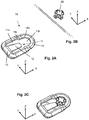
- the composite component 1 which may for example be a lateral spoiler as shown, is formed by an outer shell 2 and a support body 3 arranged on the inner face of the outer shell 2.
- the outer shell 2 and the body carrier 3 may preferably be manufactured by a plastic injection molding process.
- the support body 3 has a positioning element and the outer casing 2 and the support body 3 may, for example, as shown, be formed as elongate, substantially flat components, which extend substantially in a plane.
- this is for example represented using a Cartesian coordinate system, with X and Y axes as shown, the Z axis (not shown) extending from the plane of the image to the observer.
- the X axis and the Y axis thus correspond to the extension plane of the outer envelope 2 and the support body 3, and the Z axis corresponds to the direction of thickness of these components.
- the X axis is furthermore parallel to the mounting direction, i.e. to the direction in which the outer shell 2 and the support body 3 can be moved relative to each other to achieve the composite component 1.
- the choice of the coordinate system is however non-limiting and it is also possible to use other coordinate systems.
- the outer shell 2 and the support body 3 are not limited to flat and planar components, and may also be formed to be wholly or partly folded, curved or have any other complex shape.
- a plurality of gripper members 30 are formed at different positions on the outer casing 2 and project respectively through corresponding gripper openings 40, which are formed in the support body 3, respectively to engage with the housing. edge of the clamp element opening 40 so as to clamp the support body 3 between the clamp element 30 and the body of the outer shell 2, so as to prevent relative movement of the outer shell 2 and the support body 3 perpendicularly (in the example of the Figure 1 in the direction of the Z axis positive or negative) to the extension plane (in the example of the figure, the XY plane) of the support body 3 or the outer envelope 2 in the region of the clip element 30.
- an oblong opening 50 is furthermore formed in the support body 3, opening in which a projection 60 formed on the outer casing 2 is received.
- the width of the oblong opening 50 corresponds to the diameter of the projection 60, of such so that the oblong opening 50 provides a lateral fixation of the projection 60.
- the direction in the length of the oblong opening 50 corresponds to the direction of the X axis and the direction in the width of the oblong opening 50 corresponds to the direction of the Y axis.
- the opening oblong 50 serves to fix the projection 50 in the positive and negative direction of the Y axis, while a movement of the projection 60 in the positive and negative direction of the X axis is possible.
- projections 70 which are arranged on the edge of the outer casing 2 and engage with the support body 3.
- different fastening elements may also be provided on the support body 3, such as clipped, plug-in or screwed connection elements.
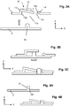
- the positioning and fixing member 10 and its interaction with the positioning protrusion 20 will now be described in more detail with reference to the Figures 2A to 2C , the Figure 2A illustrating the positioning and fixing element 10, the Figure 2B representing the positioning protrusion 20 and the Figure 3C illustrating the positioning projection 20 in the fixed state through the positioning and fixing element 10.
- the positioning and securing member 10 defines an opening 11 having a first opening portion 11a which serves to introduce the positioning projection 20 and is dimensioned in correspondence a little larger than the positioning projection 20, and having a second opening portion 11b in which the positioning projection 20 is to be held fixed once the mounting is completed.
- the direction in the length of the opening 11, namely the direction of the first opening portion 11a to the second opening portion 11b, is parallel to the X axis
- the direction in the width of the opening 11 is parallel to the Y axis.
- the positioning projection 20, in the second opening portion 11b is held fixed between a tongue 12, which covers the first opening portion 11a and extends in the example of the Figures substantially towards the X axis, and an edge 15b, which delimits and defines the second opening portion 11b, so as to prohibit a displacement of the outer casing 2 and the support body 3 relative to each other.
- the positioning protrusion 20 is held fixed by the positioning and fixing element 10 in the direction of the positive and negative X and Y axes.
- the positioning projection 20 has a circumference which has a circular shape or, as shown, coincides at least in some places with a circular shape, such as for example the cross shape shown in the figures with a circular outer circumference.
- a positioning protrusion 20 having a circular rounded circumference can be easily and easily fitted and fixed with the smallest tolerances in a correspondingly circularly shaped second opening portion 11b so as to guarantee a very precise positioning of the outer envelope 2 and the support member 3 relative to each other in the direction of the X and Y axes.
- a rotation of the outer envelope 2 and the element of 3 around the positioning projection 20 is thus prevented by the oblong opening 60 and the projection 50 attached laterally inside, that is to say in the (positive and negative) direction of the Y axis.
- the Figure 3A represents the outer casing 2 and the support body 3 in a position spaced from each other, corresponding to a situation before the beginning of the assembly of the outer casing 2 and the support body 3.
- the outer casing 2 and the support body 3 are placed against each other, the positioning projection 20 being guided inside the first opening portion 11a, by a movement towards the outside.
- the positioning projection 20 By moving the support body 3 and the outer shell 2 relative to each other in the direction of the X axis, the positioning projection 20 can be moved correspondingly under the deflected tab 12 and moved into the second opening portion 11b. If the positioning protrusion 20 is fully received in the second opening portion 11b, the pressure of the locating projection 20 against the tongue 12 is released and the tongue 12 resiliently returns to its rest position. because of the elasticity inherent in the material of the tongue, as shown on the Figure 3C . In this state, the tip of the tongue then pushes laterally against the positioning projection 20, which allows to fix and immobilize the positioning projection 20 between the tongue 12 and the edge 15b.
- the tongue 12 then snaps automatically into the holding position, in which the tongue 12 pushes against the side of the positioning projection 12 and thus fixes it in the second opening portion 11b.
- the positioning and securing member 10 and the positioning protrusion 20 thus establish a self-engaging connection, and an operator must only place the outer envelope 2 and the support body 3 against each other such that described, and move them relative to each other to achieve the composite component 1.
- the automatic latching of the positioning and fixing element 10 thus allows a very simple, error-free, rapid and ergonomic manufacture of the composite component 1.
- the positioning and fixing member 10 is formed such that the tongue 12 is easily accessible. This is due in particular to the fact that the tongue 12 is raised relative to the plane of the support body 3 and that the tongue 12 is relatively narrow with respect to the width of the first opening portion 11a. It is then easily possible for an operator, using a tool such as a lever or a pointed rod, or simply with his fingers, to be placed under the tongue 12 and lift the tongue 12, so that the tongue 12 is detached from the lateral face of the positioning projection 20 and is raised above it. The positioning projection 20 is thus released from its attachment and can be detached again and away from the positioning and fixing element 10. In this way, the composite component 1 can be removed to obtain the various components that are the outer casing 2 and the support body 3, which allows for example to replace and exchange one of the two components, for example in the case of scratch damage to the outer casing 2.
- the tab 12 is preferably formed such that it is inclined at an angle ⁇ with respect to the XY plane, where the angle ⁇ can be in the range of 5 ° to 15 °, preferably from 8 ° to 12 ° and particularly preferably from 9.5 ° to 10.5 °.
- the tongue 12, as shown is formed at a small distance from the plane of the support body 3, i.e., in the example of the Figures, shifted towards the Z axis. This is possible by turning the positioning and fixing element 10 at least in the foot area of the tongue 12 with a flange portion 13 which extends vertically from the plane of the support body 3, so that the tongue 12 is offset with respect to the plane of the support body.
- a flange portion 14 which extends vertically from the plane of the support body 3 (in the example of the Figures in the direction of the axis Z), such that the edge of the second opening portion 11b is offset from the plane of the support body 3, and is preferably offset so that the edge of the second opening portion 11b is in the same plane as the tip of the tongue 12 when the tongue 12 fixes the positioning projection 20 in the second opening portion 11b.
- the locating projection 20 further includes a recess 21 for receiving the tip of the tongue 12 so that when the locating projection 20 is secured by the tongue 12 in the second opening portion 11b, the tip of the tongue 12 is in the recess 21 and is held fixed by it.
- the tongue 12 can also ensure a fixing of the positioning projection 20 in the vertical direction, so as to prevent relative movement of the outer casing 2 and the support body 3 with respect to the other, perpendicular to the plane of extension (in the example of the Figures, the XY plane) of the support body 3 or the outer shell 2 in the area of the positioning and fixing element 10.
Landscapes
- Engineering & Computer Science (AREA)
- Mechanical Engineering (AREA)
- Connection Of Plates (AREA)
- Motor Or Generator Frames (AREA)
Applications Claiming Priority (1)
| Application Number | Priority Date | Filing Date | Title |
|---|---|---|---|
| FR1853120A FR3079806B1 (fr) | 2018-04-10 | 2018-04-10 | Composant composite pour un vehicule automobile |
Publications (2)
| Publication Number | Publication Date |
|---|---|
| EP3552885A1 true EP3552885A1 (de) | 2019-10-16 |
| EP3552885B1 EP3552885B1 (de) | 2020-12-02 |
Family
ID=63014693
Family Applications (1)
| Application Number | Title | Priority Date | Filing Date |
|---|---|---|---|
| EP19168040.4A Active EP3552885B1 (de) | 2018-04-10 | 2019-04-09 | Verbundkomponente für ein kraftfahrzeug |
Country Status (2)
| Country | Link |
|---|---|
| EP (1) | EP3552885B1 (de) |
| FR (1) | FR3079806B1 (de) |
Cited By (1)
| Publication number | Priority date | Publication date | Assignee | Title |
|---|---|---|---|---|
| EP4279337A1 (de) * | 2022-05-17 | 2023-11-22 | Lisa Dräxlmaier GmbH | Interieurelement für ein kraftfahrzeug sowie verfahren zum herstellen eines interieurelements |
Families Citing this family (1)
| Publication number | Priority date | Publication date | Assignee | Title |
|---|---|---|---|---|
| DE102022207134A1 (de) | 2022-07-12 | 2024-01-18 | Psa Automobiles Sa | Verbundbauteil, Fahrzeug mit dem Verbundbauteil sowie Montageverfahren |
Citations (7)
| Publication number | Priority date | Publication date | Assignee | Title |
|---|---|---|---|---|
| US3367082A (en) * | 1966-02-03 | 1968-02-06 | Chicago United Products Compan | Adaptor and molding assembly |
| GB1200358A (en) * | 1967-09-11 | 1970-07-29 | Warren Fastener Corp | Fastening assembly and an adaptor therefor |
| GB2040350A (en) * | 1979-01-19 | 1980-08-28 | Tucker Fasteners Ltd | Securing trim |
| GB2121099A (en) * | 1982-06-01 | 1983-12-14 | Modular Syst | Fastener clip with slip-proof locking feature for a joint structure |
| DE60014229T2 (de) * | 1999-05-07 | 2006-02-23 | Johnson Controls - Roth (S.A.S.) | Einrichtung zur Montage und Befestigung eines Verkleidungs- oder Abdeckelements |
| US20070132224A1 (en) * | 2005-12-08 | 2007-06-14 | Takata Seat Belts, Inc. | Seat belt anchor device and method |
| DE102009034584A1 (de) * | 2009-07-24 | 2010-02-25 | Daimler Ag | Befestigungseinrichtung für einen Gurtbandumlenker |
-
2018
- 2018-04-10 FR FR1853120A patent/FR3079806B1/fr not_active Expired - Fee Related
-
2019
- 2019-04-09 EP EP19168040.4A patent/EP3552885B1/de active Active
Patent Citations (7)
| Publication number | Priority date | Publication date | Assignee | Title |
|---|---|---|---|---|
| US3367082A (en) * | 1966-02-03 | 1968-02-06 | Chicago United Products Compan | Adaptor and molding assembly |
| GB1200358A (en) * | 1967-09-11 | 1970-07-29 | Warren Fastener Corp | Fastening assembly and an adaptor therefor |
| GB2040350A (en) * | 1979-01-19 | 1980-08-28 | Tucker Fasteners Ltd | Securing trim |
| GB2121099A (en) * | 1982-06-01 | 1983-12-14 | Modular Syst | Fastener clip with slip-proof locking feature for a joint structure |
| DE60014229T2 (de) * | 1999-05-07 | 2006-02-23 | Johnson Controls - Roth (S.A.S.) | Einrichtung zur Montage und Befestigung eines Verkleidungs- oder Abdeckelements |
| US20070132224A1 (en) * | 2005-12-08 | 2007-06-14 | Takata Seat Belts, Inc. | Seat belt anchor device and method |
| DE102009034584A1 (de) * | 2009-07-24 | 2010-02-25 | Daimler Ag | Befestigungseinrichtung für einen Gurtbandumlenker |
Cited By (1)
| Publication number | Priority date | Publication date | Assignee | Title |
|---|---|---|---|---|
| EP4279337A1 (de) * | 2022-05-17 | 2023-11-22 | Lisa Dräxlmaier GmbH | Interieurelement für ein kraftfahrzeug sowie verfahren zum herstellen eines interieurelements |
Also Published As
| Publication number | Publication date |
|---|---|
| FR3079806A1 (fr) | 2019-10-11 |
| FR3079806B1 (fr) | 2020-04-17 |
| EP3552885B1 (de) | 2020-12-02 |
Similar Documents
| Publication | Publication Date | Title |
|---|---|---|
| EP1095844A1 (de) | Strukturteil eines Kraftfahrzeugs, insbesondere Vorderfront | |
| EP1251285B1 (de) | Anordnung zur Zusammenstellung zweier Karrosserieteile, Kant gegen Kant , und Karrosserie , in dieser Weise zusammengesetzt | |
| EP0720935B1 (de) | Vorrichtung zur präzisen Positionierung eines Stossfängers zu einem Kotflügelteil eines Fahrzeuges | |
| EP2518336B1 (de) | Befestigungseinheit von zwei teilen eines kraftfahrzeugs | |
| EP0688695A1 (de) | Verriegelung eines beweglichen Bauteiles in einem Kraftfahrzeugsitz | |
| EP1883551B1 (de) | Vorrichtung zur fixierung eines schmuckprofilabschnitts auf einem geformten band | |
| FR2974600A1 (fr) | Dispositif de fixation par encliquetage de deux elements comprenant un bec contraint contre une surface d'engagement | |
| EP3552885B1 (de) | Verbundkomponente für ein kraftfahrzeug | |
| EP4313690B1 (de) | Stossfängerverkleidung für ein kraftfahrzeug | |
| FR3028577A1 (fr) | Dispositif de fixation par encliquetage et ensemble comprenant un tel dispositif de fixation | |
| EP2271505B1 (de) | System zum anbringen einer klemme am gehäuse eines schreibinstruments | |
| EP2127955A1 (de) | Gesamtheit aus einer Presswalze und einem ersten Karosserieteil | |
| EP3081439B1 (de) | Endstück für scheibenwischer | |
| EP1209370A1 (de) | Vorrichtung zum Befestigen eines Bauteils an einen Träger und diese Vorrichtung verwendendes System zum kontrollierten, formschlüssigen Befestigen eines hölzernen Kraftfahrzeugbauteils | |
| EP0891897B1 (de) | Flexible Schutzhülle zur Sicherung der Durchfuhr eines elektrischen Kabelbundes zwischen zwei Teilen einer Installation wie einem Kraftfahrzeug | |
| EP2168804A1 (de) | System zur Präzisionsmontage einer Tankklappe in eine Öffnung, die im Blech der Karosserie eines Kraftfahrzeugs erzeugt wurde | |
| EP0894993B1 (de) | Kupplungssteuerungsvorrichtung | |
| EP3807546B1 (de) | Befestigungsvorrichtung mit einer plattenkante angepasst zur aufnahme einer mutterklemme und eine mutterklemme | |
| FR3137357A1 (fr) | Pré-équipement pour pied milieu de véhicule automobile | |
| EP1452398B1 (de) | Zierleiste für eine Kraftfahrzeugtür und sein Herstellungsverfahren | |
| FR3019238A1 (fr) | Dispositif de fixation de deux elements de vehicule assurant une double cooperation entre lesdits elements | |
| FR3003612A1 (fr) | Procede de fixation de deux elements comprenant des organes d'encliquetage complementaires | |
| EP3673783B1 (de) | Bedienpaneel für elektrohaushaltsgerät und ein solches bedienpaneel umfassendes elektrohaushaltsgerät | |
| EP4114693B1 (de) | Kugelgelenkshalterung, pleuelstange und montageverfahren davon | |
| EP1934081B1 (de) | Abdeckung für eine lenksäule |
Legal Events
| Date | Code | Title | Description |
|---|---|---|---|
| PUAI | Public reference made under article 153(3) epc to a published international application that has entered the european phase |
Free format text: ORIGINAL CODE: 0009012 |
|
| STAA | Information on the status of an ep patent application or granted ep patent |
Free format text: STATUS: THE APPLICATION HAS BEEN PUBLISHED |
|
| AK | Designated contracting states |
Kind code of ref document: A1 Designated state(s): AL AT BE BG CH CY CZ DE DK EE ES FI FR GB GR HR HU IE IS IT LI LT LU LV MC MK MT NL NO PL PT RO RS SE SI SK SM TR |
|
| AX | Request for extension of the european patent |
Extension state: BA ME |
|
| STAA | Information on the status of an ep patent application or granted ep patent |
Free format text: STATUS: REQUEST FOR EXAMINATION WAS MADE |
|
| 17P | Request for examination filed |
Effective date: 20200416 |
|
| RBV | Designated contracting states (corrected) |
Designated state(s): AL AT BE BG CH CY CZ DE DK EE ES FI FR GB GR HR HU IE IS IT LI LT LU LV MC MK MT NL NO PL PT RO RS SE SI SK SM TR |
|
| RIC1 | Information provided on ipc code assigned before grant |
Ipc: B60R 13/02 20060101AFI20200514BHEP Ipc: F16B 5/06 20060101ALI20200514BHEP |
|
| GRAP | Despatch of communication of intention to grant a patent |
Free format text: ORIGINAL CODE: EPIDOSNIGR1 |
|
| STAA | Information on the status of an ep patent application or granted ep patent |
Free format text: STATUS: GRANT OF PATENT IS INTENDED |
|
| INTG | Intention to grant announced |
Effective date: 20200619 |
|
| GRAS | Grant fee paid |
Free format text: ORIGINAL CODE: EPIDOSNIGR3 |
|
| GRAA | (expected) grant |
Free format text: ORIGINAL CODE: 0009210 |
|
| STAA | Information on the status of an ep patent application or granted ep patent |
Free format text: STATUS: THE PATENT HAS BEEN GRANTED |
|
| AK | Designated contracting states |
Kind code of ref document: B1 Designated state(s): AL AT BE BG CH CY CZ DE DK EE ES FI FR GB GR HR HU IE IS IT LI LT LU LV MC MK MT NL NO PL PT RO RS SE SI SK SM TR |
|
| REG | Reference to a national code |
Ref country code: GB Ref legal event code: FG4D Free format text: NOT ENGLISH |
|
| REG | Reference to a national code |
Ref country code: CH Ref legal event code: EP Ref country code: AT Ref legal event code: REF Ref document number: 1340574 Country of ref document: AT Kind code of ref document: T Effective date: 20201215 |
|
| REG | Reference to a national code |
Ref country code: DE Ref legal event code: R096 Ref document number: 602019001542 Country of ref document: DE |
|
| REG | Reference to a national code |
Ref country code: IE Ref legal event code: FG4D Free format text: LANGUAGE OF EP DOCUMENT: FRENCH |
|
| PG25 | Lapsed in a contracting state [announced via postgrant information from national office to epo] |
Ref country code: FI Free format text: LAPSE BECAUSE OF FAILURE TO SUBMIT A TRANSLATION OF THE DESCRIPTION OR TO PAY THE FEE WITHIN THE PRESCRIBED TIME-LIMIT Effective date: 20201202 Ref country code: RS Free format text: LAPSE BECAUSE OF FAILURE TO SUBMIT A TRANSLATION OF THE DESCRIPTION OR TO PAY THE FEE WITHIN THE PRESCRIBED TIME-LIMIT Effective date: 20201202 Ref country code: NO Free format text: LAPSE BECAUSE OF FAILURE TO SUBMIT A TRANSLATION OF THE DESCRIPTION OR TO PAY THE FEE WITHIN THE PRESCRIBED TIME-LIMIT Effective date: 20210302 Ref country code: GR Free format text: LAPSE BECAUSE OF FAILURE TO SUBMIT A TRANSLATION OF THE DESCRIPTION OR TO PAY THE FEE WITHIN THE PRESCRIBED TIME-LIMIT Effective date: 20210303 |
|
| REG | Reference to a national code |
Ref country code: NL Ref legal event code: MP Effective date: 20201202 |
|
| REG | Reference to a national code |
Ref country code: AT Ref legal event code: MK05 Ref document number: 1340574 Country of ref document: AT Kind code of ref document: T Effective date: 20201202 |
|
| PG25 | Lapsed in a contracting state [announced via postgrant information from national office to epo] |
Ref country code: BG Free format text: LAPSE BECAUSE OF FAILURE TO SUBMIT A TRANSLATION OF THE DESCRIPTION OR TO PAY THE FEE WITHIN THE PRESCRIBED TIME-LIMIT Effective date: 20210302 Ref country code: PL Free format text: LAPSE BECAUSE OF FAILURE TO SUBMIT A TRANSLATION OF THE DESCRIPTION OR TO PAY THE FEE WITHIN THE PRESCRIBED TIME-LIMIT Effective date: 20201202 Ref country code: LV Free format text: LAPSE BECAUSE OF FAILURE TO SUBMIT A TRANSLATION OF THE DESCRIPTION OR TO PAY THE FEE WITHIN THE PRESCRIBED TIME-LIMIT Effective date: 20201202 Ref country code: SE Free format text: LAPSE BECAUSE OF FAILURE TO SUBMIT A TRANSLATION OF THE DESCRIPTION OR TO PAY THE FEE WITHIN THE PRESCRIBED TIME-LIMIT Effective date: 20201202 |
|
| PG25 | Lapsed in a contracting state [announced via postgrant information from national office to epo] |
Ref country code: NL Free format text: LAPSE BECAUSE OF FAILURE TO SUBMIT A TRANSLATION OF THE DESCRIPTION OR TO PAY THE FEE WITHIN THE PRESCRIBED TIME-LIMIT Effective date: 20201202 Ref country code: HR Free format text: LAPSE BECAUSE OF FAILURE TO SUBMIT A TRANSLATION OF THE DESCRIPTION OR TO PAY THE FEE WITHIN THE PRESCRIBED TIME-LIMIT Effective date: 20201202 |
|
| REG | Reference to a national code |
Ref country code: LT Ref legal event code: MG9D |
|
| PG25 | Lapsed in a contracting state [announced via postgrant information from national office to epo] |
Ref country code: CZ Free format text: LAPSE BECAUSE OF FAILURE TO SUBMIT A TRANSLATION OF THE DESCRIPTION OR TO PAY THE FEE WITHIN THE PRESCRIBED TIME-LIMIT Effective date: 20201202 Ref country code: EE Free format text: LAPSE BECAUSE OF FAILURE TO SUBMIT A TRANSLATION OF THE DESCRIPTION OR TO PAY THE FEE WITHIN THE PRESCRIBED TIME-LIMIT Effective date: 20201202 Ref country code: SM Free format text: LAPSE BECAUSE OF FAILURE TO SUBMIT A TRANSLATION OF THE DESCRIPTION OR TO PAY THE FEE WITHIN THE PRESCRIBED TIME-LIMIT Effective date: 20201202 Ref country code: SK Free format text: LAPSE BECAUSE OF FAILURE TO SUBMIT A TRANSLATION OF THE DESCRIPTION OR TO PAY THE FEE WITHIN THE PRESCRIBED TIME-LIMIT Effective date: 20201202 Ref country code: LT Free format text: LAPSE BECAUSE OF FAILURE TO SUBMIT A TRANSLATION OF THE DESCRIPTION OR TO PAY THE FEE WITHIN THE PRESCRIBED TIME-LIMIT Effective date: 20201202 Ref country code: RO Free format text: LAPSE BECAUSE OF FAILURE TO SUBMIT A TRANSLATION OF THE DESCRIPTION OR TO PAY THE FEE WITHIN THE PRESCRIBED TIME-LIMIT Effective date: 20201202 Ref country code: PT Free format text: LAPSE BECAUSE OF FAILURE TO SUBMIT A TRANSLATION OF THE DESCRIPTION OR TO PAY THE FEE WITHIN THE PRESCRIBED TIME-LIMIT Effective date: 20210405 |
|
| PG25 | Lapsed in a contracting state [announced via postgrant information from national office to epo] |
Ref country code: AT Free format text: LAPSE BECAUSE OF FAILURE TO SUBMIT A TRANSLATION OF THE DESCRIPTION OR TO PAY THE FEE WITHIN THE PRESCRIBED TIME-LIMIT Effective date: 20201202 |
|
| REG | Reference to a national code |
Ref country code: DE Ref legal event code: R097 Ref document number: 602019001542 Country of ref document: DE |
|
| PG25 | Lapsed in a contracting state [announced via postgrant information from national office to epo] |
Ref country code: IS Free format text: LAPSE BECAUSE OF FAILURE TO SUBMIT A TRANSLATION OF THE DESCRIPTION OR TO PAY THE FEE WITHIN THE PRESCRIBED TIME-LIMIT Effective date: 20210402 |
|
| PLBE | No opposition filed within time limit |
Free format text: ORIGINAL CODE: 0009261 |
|
| STAA | Information on the status of an ep patent application or granted ep patent |
Free format text: STATUS: NO OPPOSITION FILED WITHIN TIME LIMIT |
|
| PG25 | Lapsed in a contracting state [announced via postgrant information from national office to epo] |
Ref country code: IT Free format text: LAPSE BECAUSE OF FAILURE TO SUBMIT A TRANSLATION OF THE DESCRIPTION OR TO PAY THE FEE WITHIN THE PRESCRIBED TIME-LIMIT Effective date: 20201202 Ref country code: AL Free format text: LAPSE BECAUSE OF FAILURE TO SUBMIT A TRANSLATION OF THE DESCRIPTION OR TO PAY THE FEE WITHIN THE PRESCRIBED TIME-LIMIT Effective date: 20201202 |
|
| 26N | No opposition filed |
Effective date: 20210903 |
|
| PG25 | Lapsed in a contracting state [announced via postgrant information from national office to epo] |
Ref country code: DK Free format text: LAPSE BECAUSE OF FAILURE TO SUBMIT A TRANSLATION OF THE DESCRIPTION OR TO PAY THE FEE WITHIN THE PRESCRIBED TIME-LIMIT Effective date: 20201202 Ref country code: SI Free format text: LAPSE BECAUSE OF FAILURE TO SUBMIT A TRANSLATION OF THE DESCRIPTION OR TO PAY THE FEE WITHIN THE PRESCRIBED TIME-LIMIT Effective date: 20201202 Ref country code: MC Free format text: LAPSE BECAUSE OF FAILURE TO SUBMIT A TRANSLATION OF THE DESCRIPTION OR TO PAY THE FEE WITHIN THE PRESCRIBED TIME-LIMIT Effective date: 20201202 |
|
| PG25 | Lapsed in a contracting state [announced via postgrant information from national office to epo] |
Ref country code: LU Free format text: LAPSE BECAUSE OF NON-PAYMENT OF DUE FEES Effective date: 20210409 |
|
| REG | Reference to a national code |
Ref country code: BE Ref legal event code: MM Effective date: 20210430 |
|
| PG25 | Lapsed in a contracting state [announced via postgrant information from national office to epo] |
Ref country code: ES Free format text: LAPSE BECAUSE OF FAILURE TO SUBMIT A TRANSLATION OF THE DESCRIPTION OR TO PAY THE FEE WITHIN THE PRESCRIBED TIME-LIMIT Effective date: 20201202 |
|
| PG25 | Lapsed in a contracting state [announced via postgrant information from national office to epo] |
Ref country code: IE Free format text: LAPSE BECAUSE OF NON-PAYMENT OF DUE FEES Effective date: 20210409 |
|
| PG25 | Lapsed in a contracting state [announced via postgrant information from national office to epo] |
Ref country code: IS Free format text: LAPSE BECAUSE OF FAILURE TO SUBMIT A TRANSLATION OF THE DESCRIPTION OR TO PAY THE FEE WITHIN THE PRESCRIBED TIME-LIMIT Effective date: 20210402 |
|
| PG25 | Lapsed in a contracting state [announced via postgrant information from national office to epo] |
Ref country code: BE Free format text: LAPSE BECAUSE OF NON-PAYMENT OF DUE FEES Effective date: 20210430 |
|
| REG | Reference to a national code |
Ref country code: CH Ref legal event code: PL |
|
| PG25 | Lapsed in a contracting state [announced via postgrant information from national office to epo] |
Ref country code: LI Free format text: LAPSE BECAUSE OF NON-PAYMENT OF DUE FEES Effective date: 20220430 Ref country code: CH Free format text: LAPSE BECAUSE OF NON-PAYMENT OF DUE FEES Effective date: 20220430 |
|
| P01 | Opt-out of the competence of the unified patent court (upc) registered |
Effective date: 20230517 |
|
| PG25 | Lapsed in a contracting state [announced via postgrant information from national office to epo] |
Ref country code: CY Free format text: LAPSE BECAUSE OF FAILURE TO SUBMIT A TRANSLATION OF THE DESCRIPTION OR TO PAY THE FEE WITHIN THE PRESCRIBED TIME-LIMIT Effective date: 20201202 |
|
| PG25 | Lapsed in a contracting state [announced via postgrant information from national office to epo] |
Ref country code: HU Free format text: LAPSE BECAUSE OF FAILURE TO SUBMIT A TRANSLATION OF THE DESCRIPTION OR TO PAY THE FEE WITHIN THE PRESCRIBED TIME-LIMIT; INVALID AB INITIO Effective date: 20190409 |
|
| GBPC | Gb: european patent ceased through non-payment of renewal fee |
Effective date: 20230409 |
|
| PG25 | Lapsed in a contracting state [announced via postgrant information from national office to epo] |
Ref country code: GB Free format text: LAPSE BECAUSE OF NON-PAYMENT OF DUE FEES Effective date: 20230409 |
|
| PG25 | Lapsed in a contracting state [announced via postgrant information from national office to epo] |
Ref country code: GB Free format text: LAPSE BECAUSE OF NON-PAYMENT OF DUE FEES Effective date: 20230409 |
|
| PG25 | Lapsed in a contracting state [announced via postgrant information from national office to epo] |
Ref country code: MK Free format text: LAPSE BECAUSE OF FAILURE TO SUBMIT A TRANSLATION OF THE DESCRIPTION OR TO PAY THE FEE WITHIN THE PRESCRIBED TIME-LIMIT Effective date: 20201202 |
|
| REG | Reference to a national code |
Ref country code: DE Ref legal event code: R081 Ref document number: 602019001542 Country of ref document: DE Owner name: OPMOBILITY SE, FR Free format text: FORMER OWNER: COMPAGNIE PLASTIC OMNIUM SE, LYON, FR Ref country code: DE Ref legal event code: R081 Ref document number: 602019001542 Country of ref document: DE Owner name: OPMOBILITY SE, FR Free format text: FORMER OWNER: COMPAGNIE PLASTIC OMNIUM, LYON, FR |
|
| PG25 | Lapsed in a contracting state [announced via postgrant information from national office to epo] |
Ref country code: MT Free format text: LAPSE BECAUSE OF FAILURE TO SUBMIT A TRANSLATION OF THE DESCRIPTION OR TO PAY THE FEE WITHIN THE PRESCRIBED TIME-LIMIT Effective date: 20201202 |
|
| PGFP | Annual fee paid to national office [announced via postgrant information from national office to epo] |
Ref country code: DE Payment date: 20250422 Year of fee payment: 7 |
|
| PGFP | Annual fee paid to national office [announced via postgrant information from national office to epo] |
Ref country code: FR Payment date: 20250429 Year of fee payment: 7 |
|
| PG25 | Lapsed in a contracting state [announced via postgrant information from national office to epo] |
Ref country code: TR Free format text: LAPSE BECAUSE OF FAILURE TO SUBMIT A TRANSLATION OF THE DESCRIPTION OR TO PAY THE FEE WITHIN THE PRESCRIBED TIME-LIMIT Effective date: 20201202 |