EP3552885B1 - Verbundkomponente für ein kraftfahrzeug - Google Patents
Verbundkomponente für ein kraftfahrzeug Download PDFInfo
- Publication number
- EP3552885B1 EP3552885B1 EP19168040.4A EP19168040A EP3552885B1 EP 3552885 B1 EP3552885 B1 EP 3552885B1 EP 19168040 A EP19168040 A EP 19168040A EP 3552885 B1 EP3552885 B1 EP 3552885B1
- Authority
- EP
- European Patent Office
- Prior art keywords
- positioning
- opening portion
- support body
- outer casing
- composite component
- Prior art date
- Legal status (The legal status is an assumption and is not a legal conclusion. Google has not performed a legal analysis and makes no representation as to the accuracy of the status listed.)
- Active
Links
Images


Classifications
-
- B—PERFORMING OPERATIONS; TRANSPORTING
- B60—VEHICLES IN GENERAL
- B60R—VEHICLES, VEHICLE FITTINGS, OR VEHICLE PARTS, NOT OTHERWISE PROVIDED FOR
- B60R13/00—Elements for body-finishing, identifying, or decorating; Arrangements or adaptations for advertising purposes
- B60R13/02—Internal Trim mouldings ; Internal Ledges; Wall liners for passenger compartments; Roof liners
- B60R13/0206—Arrangements of fasteners and clips specially adapted for attaching inner vehicle liners or mouldings
-
- F—MECHANICAL ENGINEERING; LIGHTING; HEATING; WEAPONS; BLASTING
- F16—ENGINEERING ELEMENTS AND UNITS; GENERAL MEASURES FOR PRODUCING AND MAINTAINING EFFECTIVE FUNCTIONING OF MACHINES OR INSTALLATIONS; THERMAL INSULATION IN GENERAL
- F16B—DEVICES FOR FASTENING OR SECURING CONSTRUCTIONAL ELEMENTS OR MACHINE PARTS TOGETHER, e.g. NAILS, BOLTS, CIRCLIPS, CLAMPS, CLIPS OR WEDGES; JOINTS OR JOINTING
- F16B5/00—Joining sheets or plates, e.g. panels, to one another or to strips or bars parallel to them
- F16B5/06—Joining sheets or plates, e.g. panels, to one another or to strips or bars parallel to them by means of clamps or clips
- F16B5/0607—Joining sheets or plates, e.g. panels, to one another or to strips or bars parallel to them by means of clamps or clips joining sheets or plates to each other
- F16B5/0621—Joining sheets or plates, e.g. panels, to one another or to strips or bars parallel to them by means of clamps or clips joining sheets or plates to each other in parallel relationship
- F16B5/0664—Joining sheets or plates, e.g. panels, to one another or to strips or bars parallel to them by means of clamps or clips joining sheets or plates to each other in parallel relationship at least one of the sheets or plates having integrally formed or integrally connected snap-in-features
Definitions
- the present invention relates to a composite component for a motor vehicle.
- Trim elements formed as composite components are often used in motor vehicles such as, for example, a side member trim, side spoiler, rear spoiler, bumper, grille or parts of these.
- Composite components are usually fabricated in a shell-like structure, comprising an outer shell generally painted in the body color, and a support body which is connected to the outer shell and which secures, using fasteners, the composite component thus obtained to a part of the vehicle.
- DE 600 14 229 T2 discloses a composite component for a motor vehicle having an outer shell and a support body, wherein a positioning and fixing member is formed in the support body, which positioning and fixing member defines an opening with a first portion of 'opening and a second opening portion, wherein the second opening portion is designed such that a positioning projection formed on the outer casing can be positioned in the second opening portion, to be held there and secured by an edge of the second opening portion, wherein the first opening portion is formed larger than the second opening portion, and wherein an edge portion is formed by narrowing in the width of opening in a transition zone from the edge of the first opening part to the edge of the second opening part, for guiding the positioning projection in the second opening party.
- a side spoiler for a motor vehicle comprising a spoiler element forming the outer profile and a support member arranged on the inner face and can be connected to the spoiler element.
- the spoiler element has, along its longitudinal sides, a first lateral edge and a second lateral edge opposite it, in which the first lateral edge is formed at least in part by a fold which forms an undercut with the inner face, and wherein the second side edge is formed by a flange projecting from the inner face.
- the support element extends, in the connected state, at least in part from the first lateral edge to the second lateral edge, in which the support element is then connected to the first lateral edge by complementarity of shapes with at least one bearing zone on the undercut, and the support element is also connected to the second lateral edge by means of at least one snap connection.
- the snap connection is formed by a snap member which protrudes from the flange and forms a channel with the inner face, and by means of a complementary snap member formed on the support member and received in the canal. The spoiler element and the support element can thus, by insertion, be connected to each other in a single assembly direction.
- the ratchet elements inherently have a certain amount of play and tolerance, so that it is also possible to achieve a slight offset of the spoiler element, but all the same visually or tactilely noticeable, even in the event of a correctly realized snap-in of the spoiler element and the support element, in particular when a force is applied, such as for example exerted by a hand application, which is unsatisfactory, in particular for high-end motor vehicles.
- connection between the support element and the spoiler element is only at the edges when, for example, there is no connection at the center of the elements in such a way. that, for example for reasons of temperature variations and therefore of different expansions which go hand in hand between the support element and the spoiler element, an annoying clicking noise may appear.
- the document DE 10 2017 007 530 A1 provides a composite component for a vehicle, comprising an outer shell and a support body held in the outer shell by complementarity of shapes, wherein the support body has an elastic foam.
- the foam of the support body can rest flexibly against the outer shell, effectively preventing rattling of the support body in the outer shell.
- the composite elements disclosed by this document also present the problems resulting from bonding only at the edges of the outer shell and the support body, as well as the need for careful bonding.
- this styling element comprising first and second elements which respectively form a fastener in the X direction for fixing the style element on the body part.
- the first element cooperates with a first locking opening in the Z direction, the second element with a second locking opening in the Y direction.
- EP 1 442 941 A1 it is also known to form a protective or decorative strip for the body of a motor vehicle with an integrated fixing clamp which comprises a clamp head connected to the rest of the clamp by a strip, in which the fixing clamp cooperates with a "keyhole" opening in the body.
- the object of the present invention is therefore to provide a composite part for a motor vehicle which overcomes the aforementioned drawbacks.
- the present invention also aims to provide a composite part for a motor vehicle in which the outer casing and the support body can be fixed with respect to one another in a very precise manner.
- Another object of the present invention is to provide a composite part for a motor vehicle which can be manufactured in a simple, safe and economical manner.
- a composite component for a motor vehicle comprising an outer casing and a support body, in which a positioning and fixing member is formed in the support body and defines a opening having a first opening portion and a second opening portion, wherein the positioning and securing member has a tab which extends from a side edge of the first opening portion towards the second portion opening and covers the first opening portion, wherein the second opening portion is designed such that a positioning protrusion formed on the outer casing can be positioned in the second opening portion, therein be held and fixed by one edge of the second opening part and the tongue, so as to prohibit relative movements of the outer casing and of the support body with respect to one another be, parallel to the plane of extension of the support body or of the outer casing in the area of the positioning and fixing element, in which the first opening part is made larger than the second opening part , wherein the positioning and fixing member is formed such that to position the positioning projection in the second opening part, the positioning projection can first be engaged in the first opening part, in order to to to
- the composite component allows, in particular due to the positioning and fixing element provided as indicated, a simple and light connection of the outer shell and the support body, by placing them side by side. each other and inserting them into each other.
- the same positioning and fixing element allows very precise fixing of the outer shell and the supporting body in two orthogonal directions (directions in the plane of the shell or the supporting body), the protrusion of positioning of the tongue being held and fixed in the second opening part.
- the positioning projection is thus maintained on its lateral periphery at four points (each time opposed in pairs to each other) so as to allow very precise fixing and positioning and practically without play.
- the positioning and fixing element can be provided in almost any position on the support body, allowing a designer of the composite component to provide the positioning and fixing element in an interior area of the support body, instead of being limited to one edge thereof, so that the arrangement of the positioning and fixing element is possible precisely where the highest loads or shear forces are expected and / or there where the highest demands are made on precise and backlash-free fastening.
- the "snap" of the tab on the positioning protrusion can be easily and clearly detected acoustically, visually and haptically when properly inserted into each other, thus avoiding further easily unintentional improper assembly.
- the positioning and fixing member is preferably formed such that the tab automatically rebounds from the deflected state to push against a side surface of the positioning member.
- the tongue thus engages automatically to push against the side of the positioning projection and thereby secure the latter in the second opening portion.
- the positioning and fixing element and the positioning projection thus constitute a self-locking connection.
- provision can also be made to incline the tongue in its rest position at a certain angle with respect to the plane of the support body.
- the angle can in particular be in the range of 5 ° to 15 °, more preferably in the range of 8 ° to 12 °, and more preferably in the range of 9.5 ° to 10.5 °.
- the tab on the positioning projection takes place more easily when they are correctly inserted into each other: while the locating protrusion pushes against and deflects the tab when inserted into each other so that the tilt decreases, or depending on the interpretation, that tilt occurs if
- the tab can slide over an edge of the locating protrusion and resiliently returns to the rest position. This ensures on the one hand that the tip of the tongue does not slide easily over the side of the positioning projection (more or less defined according to the friction) but always returns elastically to the desired position and thus always presses and fixes on the same lateral side of the positioning projection.
- the quick click-in ensures a clearly noticeable visual and haptic feedback so that a clear confirmation of the correct installation is given to the operator.
- the offset of the tongue foot caused by the collar portion may be 1mm, 2mm, 3mm or more.
- the offset of the tongue foot caused by the flange portion is preferably greater than the height of the locating protrusion above the outer casing, is more preferably 0.5 to 3.0 mm greater. , more preferably 1.0 to 2.5 mm more, still more preferably 1.5 to 2.0 mm.
- the first opening part is then easily accessible, so that the positioning projection can be easily engaged therein. This facilitates the initial positioning of the outer shell and the support body relative to each other, so that assembly is facilitated.
- the offset of the tongue foot is slightly greater than the height of the positioning protrusion. This has the effect that when the locating protrusion is pushed against the tab and moved along it, the tab is only deflected horizontally (i.e. parallel to the support member. ), but is not folded beyond it. It is thus possible to avoid excessive bending of the tongue and therefore to avoid the risk of weakening the material.
- the inclination of the tongue ensures that the tip of the tongue is, in the snap-in position (corresponding to the rest position), again at a height which allows a secure fixing of the projection. positioning.
- the positioning and fixing element at least in the area of the second opening part with a flange part which extends vertically from the plane of the support body, so that the edge of the second opening portion is offset from the plane of the support body, and is preferably offset such that the edge of the second opening portion is in the same plane as the tip of the tongue when the tongue fixes the positioning projection in the second opening portion.
- This measurement makes it possible to ensure that the four points, at which the positioning projection is fixed laterally, are all located in the same plane parallel to the plane of the support body or of the outer casing. This thus makes it possible to prevent any undesirable tilting torques from appearing.
- the first opening portion may be provided to be formed substantially rectangular and / or to have a width and / or a length which is greater by at least 0.5 mm, preferably at least. 1.0mm, than a diameter of the positioning protrusion.
- the tongue extends over a length of between 10 mm and 30 mm, preferably between 12 mm and 25 mm, particularly preferably between 15 mm and 20 mm.
- the positioning projection has a recess to receive the tip of the tongue.
- the tongue cooperates with the recess so as to prohibit relative movement of the outer shell and the support body with respect to each other. the other perpendicular to the plane of extension of the support body or of the outer casing in the zone of the positioning and fixing element.
- the positioning and fixing element ensures a fixing at six points, that is to say also in the direction (positive and negative) of the verticals.
- the degree of fixing can be further increased and one or more required fixing means can be omitted in the direction (positive and negative) of the verticals.
- the positioning and fixing member is formed such that the tongue can be lifted or deflected by an operator or tool, so that the tongue no longer presses against the side surface of the positioning member. , and can be moved by relative movement of the outer shell and the supporting body of the locating protrusion, from the second opening portion into the first opening portion, so that the outer shell and support body can be separated from each other.
- the composite component can thus easily be broken down again into its constituent elements, so that when the visible side of the outer casing is for example scratched, only the latter needs to be replaced, instead of replacing the whole. of the composite component. This makes it possible to simplify a repair and / or to make it more economical.
- the height at which the clamp member protrudes from the outer casing can be provided to be substantially equal to the height at which the positioning protrusion protrudes from the outer casing, a difference in height preferably being less than 1.5 mm, more preferably less than 1.0 mm, and even more preferably less than 0.5 mm.
- the indicated measurement ensures that the outer casing and the support body are placed and moved in a simple way relative to each other, so that an operator can carry out the assembly quickly and safely .
- the gripper member opening is arranged and dimensioned such that when the gripper member is introduced into the gripper member opening, the locating protrusion is in the area of the first. opening part, preferably at a distance of at least 0.2 mm, preferably at least 0.5 mm from the edge of the first opening part.
- the clamp member openings and the clamp member or members can in this way be a kind of positioning aid, so as to easily and definitively engage the positioning protrusion in the first opening part and to be placed in relation to the tongue to facilitate assembly of the composite component.
- At least one oblong opening may be formed in the support body and is formed to receive a protrusion formed on the outer casing, the oblong opening having a width which corresponds to the diameter of the protrusion.
- the combination of the oblong opening and the protrusion provides additional two-point fixation, so as to prohibit relative movement between the outer shell and the support body in a direction orthogonal to the longitudinal direction of the oblong opening.
- several oblong openings can also be provided with respectively associated projections, to ensure a high level of positioning accuracy over the entire composite component.
- At least one fastener may further be formed or arranged on the support body to secure the composite component to a part of a vehicle.
- the fastening element or elements may be formed in a manner known per se as one or more clipped, clipped or screwed connecting elements.
- the composite component may be formed as a trim element of a motor vehicle such as, for example, as a side member trim, a spoiler such as a side spoiler or a rear spoiler, a bumper or part of it. this, or a grille or part of it.
- the composite component 1 which can for example be a side spoiler as shown, is formed by an outer casing 2 and a support body 3 arranged on the inner face of the outer casing 2.
- the carrier 3 can preferably be manufactured by a plastic injection molding process.
- the support body 3 has a positioning element and fixing 10 which cooperates with a positioning projection 20 formed on the outer casing 2.
- the outer casing 2 and the support body 3 may for example, as shown, be formed as oblong, substantially flat components which s' extend substantially in a plane. On the Figure 1 , this is for example represented using a Cartesian coordinate system, with X and Y axes as shown, the Z axis (not shown) extending from the plane of the image towards the observer.
- the X axis and the Y axis thus correspond to the extension plane of the outer shell 2 and of the support body 3, and the Z axis corresponds to the thickness direction of these components.
- the X axis is further parallel to the mounting direction, i.e. the direction in which the outer shell 2 and the support body 3 can be moved relative to each other to produce the composite component 1.
- the choice of the coordinate system is, however, non-limiting and it is also possible to use other coordinate systems.
- the outer shell 2 and the support body 3 are not limited to flat and planar components, and can also be formed to be wholly or partly bent, curved or have any other complex shape.
- gripper elements 30 are formed at different positions on the outer casing 2 and respectively protrude through corresponding gripper openings 40, which are formed in the support body 3, to respectively engage with the edge of the gripper member opening 40 so as to clamp the support body 3 between the gripper member 30 and the body of the outer casing 2, so as to prevent relative movement of the outer casing 2 and the support body 3 perpendicularly (in the example of Figure 1 direction of the positive or negative Z axis) to the extension plane (in the example of the figure, the XY plane) of the support body 3 or of the outer shell 2 in the area of the gripper element 30.
- an oblong opening 50 is further formed in the support body 3, in which opening is received a projection 60 formed on the outer casing 2.
- the width of the oblong opening 50 corresponds to the diameter of the projection 60, so so that the oblong opening 50 provides lateral attachment of the projection 60.
- the direction in the length of the oblong opening 50 corresponds to the direction of the X axis and the direction in the width of the oblong opening 50 corresponds to the direction of the Y axis.
- the opening oblong 50 serves to fix the protrusion 50 in the positive and negative direction of the Y axis, while movement of the protrusion 60 in the positive and negative direction of the X axis is possible.
- protrusions 70 which are arranged on the edge of the outer casing 2 and come into engagement with the support body 3.
- different fixing elements can also be provided on the support body 3, such as clip-on, plug-in or screw-on connecting elements.
- the positioning and fixing member 10 defines an opening 11 having a first opening portion 11a which serves to introduce the positioning protrusion 20 and is correspondingly dimensioned somewhat larger than the positioning protrusion 20, and comprising a second opening portion 11b in which the positioning projection 20 is to be kept fixed once the assembly has been carried out.
- the direction along the length of the opening 11, namely the direction from the first opening part 11a to the second opening part 11b, is parallel to the X axis
- the direction in the width of the opening 11 is parallel to the Y axis.
- the positioning projection 20, in the second opening part 11b is kept fixed between a tongue 12, which covers the first opening part 11a and extends in the example of the Figures substantially in the direction of the 'axis X, and an edge 15b, which delimits and defines the second opening part 11b, so as to prevent movement of the outer casing 2 and of the support body 3 relative to each other.
- the positioning protrusion 20 is kept fixed by the positioning and fixing member 10 in the direction of the positive and negative X and Y axes.
- the positioning protrusion 20 has a circumference which has a circular shape or, as shown, coincides at least in places with a circular shape, such as for example the cross shape shown in the figures with a circular outer circumference.
- a positioning protrusion 20 having a circular rounded circumference can be inserted and fixed easily and snugly with the smallest tolerances in a correspondingly circularly shaped second opening portion 11b, so as to ensure very precise positioning of the outer casing 2 and the support element 3 with respect to each other in the direction of the X and Y axes.
- a rotation of the outer casing 2 and of the support 3 around the positioning projection 20 is thus prevented by the oblong opening 60 and the projection 50 fixed inside laterally, that is to say in the direction (positive and negative) of the Y axis.
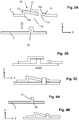
- the Figure 3A shows the outer shell 2 and the support body 3 in a position spaced apart from each other, corresponding to a situation before the start of the assembly of the outer shell 2 and the support body 3.
- the outer casing 2 and the supporting body 3 are placed against each other, the positioning projection 20 being guided inside the first opening part 11a, by a movement in the direction of the 'axis Z, and pushed against the tongue 12, which extends from the edge 15a which delimits and defines the first opening part 11a, towards the opposite edge 15b, so that the tongue 12 is folded back and deflected from it. its resting position (as shown on the Figure 3A ) until the complete reception of the positioning projection 20 in the first opening part 11a (as shown in Figure 3B ).
- the positioning protrusion 20 can be moved correspondingly under the deflected tab 12 and be moved in the second opening part 11b. If the locating protrusion 20 is fully received in the second opening portion 11b, the pressure of the locating protrusion 20 against the tongue 12 releases and the tongue 12 resiliently returns to its rest position in due to the elasticity inherent in the tongue material, as shown in the Figure 3C . In this state, the tip of the tongue then pushes laterally against the positioning projection 20, which makes it possible to fix and immobilize the positioning projection 20 between the tongue 12 and the edge 15b.
- the tongue 12 then engages automatically in the holding position, in which the tongue 12 pushes against the side of the positioning projection 12 and thus fixes the latter in the second opening part 11b.
- the positioning and fixing member 10 and the positioning protrusion 20 thus establish a self-locking connection, and an operator only needs to place the outer shell 2 and the support body 3 against each other such that described, and move them with respect to each other to produce the composite component 1.
- the automatic snap-in of the positioning and fixing element 10 therefore allows very simple, error-free, rapid and ergonomic manufacture of the composite component 1.
- the simple production of the composite component 1 by simple juxtaposition and displacement of the outer casing 2 and the support body 3 with respect to each other makes the production of the composite component 1 also perfectly suited to automated production, in which the juxtaposition and movement of the outer casing 2 and of the support body 3 with respect to each other are carried out by corresponding devices.
- the positioning and fixing member 10 is formed such that the tab 12 is easily accessible. This is in particular due to the fact that the tongue 12 is raised relative to the plane of the support body 3 and that the tongue 12 is relatively narrow with respect to the width of the first opening part 11a. It is then easily possible for an operator, using a tool such as a lever or a pointed rod, or quite simply with his fingers, to place himself under the tongue 12 and lift the tongue 12, so that the tongue 12 detaches from the side face of the positioning projection 20 and is raised above it. The positioning projection 20 is thus released from its fixing and can be again detached and moved away from the positioning and fixing element 10. In this way, the composite component 1 can be disassembled to obtain the different components that are the. outer casing 2 and the support body 3, which makes it possible for example to replace and exchange one of the two components, for example in the event of damage by scratching of the outer casing 2.
- the tab 12 is preferably formed such that it is inclined at an angle ⁇ with respect to the XY plane, where the angle ⁇ may be in the range of 5 ° to 15 °, preferably. from 8 ° to 12 ° and particularly preferably from 9.5 ° to 10.5 °.
- the tongue 12, as shown is formed at a small distance from the plane of the support body 3, that is to say, in the example of the Figures, offset in the direction of the Z axis. This is possible by rotating the positioning and fixing element 10 at least in the region of the foot of the tongue 12 with a flange part 13 which extends vertically from the plane of the support body 3, so that the tongue 12 is offset from the plane of the support body.
- a flange part 14 which extends vertically from the plane of the support body 3 (in the example of the Figures in the direction of the axis Z), so that the edge of the second opening portion 11b is offset from the plane of the supporting body 3, and is preferably offset such that the edge of the second opening portion 11b lies in the same plane as the tip of the tongue 12 when the tongue 12 fixes the positioning projection 20 in the second opening portion 11b.
- the positioning protrusion 20 further includes a recess 21 for receiving the tip of the tongue 12 such that when the positioning protrusion 20 is secured by the tongue 12 in the second opening portion 11b, the tip of the tongue 12 is located in the recess 21 and is kept fixed by the latter.
- the tab 12 can also secure the positioning projection 20 in the vertical direction, so as to prohibit relative movement of the outer casing 2 and the support body 3 with respect to one another. other, perpendicular to the extension plane (in the example of the Figures, the XY plane) of the support body 3 or of the outer casing 2 in the area of the positioning and fixing element 10.
Landscapes
- Engineering & Computer Science (AREA)
- Mechanical Engineering (AREA)
- Connection Of Plates (AREA)
- Motor Or Generator Frames (AREA)
Claims (16)
- Verbundbauteil (1) für ein Kraftfahrzeug, aufweisend eine Außenhülle (2) und einen Stützkörper (3),
wobei in dem Tragkörper (3) ein Positionierungs- und Befestigungselement (10) ausgebildet ist, welches eine Öffnung (11) mit einem ersten Öffnungsabschnitt (11a) und einem zweiten Öffnungsabschnitt (11b) definiert,
wobei das Positionierungs- und Befestigungselement (10) eine Zunge (12) aufweist, die sich von einer Seitenkante (15a) des ersten Öffnungsabschnitts (11a) in Richtung des zweiten Öffnungsabschnitts (11b) erstreckt und den ersten Öffnungsabschnitt (11a) abdeckt,
wobei der zweite Öffnungsabschnitt (11b) so gestaltet ist, dass ein an der Außenhülle (2) ausgebildeter Positionierungsvorsprung (20) in dem zweiten Öffnungsabschnitt (11b) positioniert werden kann, dort durch einen Rand (15b) des zweiten Öffnungsabschnitts (11b) und die Zunge (12) gehalten und fixiert werden, um Relativbewegungen der Außenhülle (2) und des Stützkörpers (3) zueinander parallel zur Erstreckungsebene des Stützkörpers (3) oder der Außenhülle (2) im Bereich des Positionierungs- und Befestigungselements (10) zu verhindern, wobei der erste Öffnungsabschnitt (11a) größer als der zweite Öffnungsabschnitt (11b) ausgebildet ist,
wobei das Positionierungs- und Befestigungselement (10) so ausgebildet ist, dass zum Positionieren des Positionierungsvorsprungs (20) in dem zweiten Öffnungsabschnitt (11b) der Positionierungsvorsprung (20) zunächst in den ersten Öffnungsabschnitt (11a) eingreifen kann, um gegen die Zunge (12) zu drücken und sie aus ihrer Ruheposition abzulenken, das Positionierungselement (20) mittels einer Relativbewegung der Außenhülle (2) und des Stützkörpers (3) in Richtung des zweiten Öffnungsabschnitts (11b) bewegt werden kann, wobei, wenn der Positionierungsvorsprung (20) vollständig in den zweiten Öffnungsabschnitt (11b) bewegt und darin positioniert wird, die Zunge (12) zumindest teilweise aus dem abgelenkten Zustand zurückfedert, um gegen eine Seitenfläche des Positionierungselements (20) zu drücken, so dass das Positionierungselement in der durch die Zunge (12) und den Rand (15b) des zweiten Öffnungsabschnitts (11b) definierten Position fixiert ist,
wobei ein Kantenabschnitt (15c) durch Verengung der Öffnungsbreite in einem Übergangsbereich von der Kante (15a) des ersten Öffnungsabschnitts (11a) zu der Kante (15b) des zweiten Öffnungsabschnitts (11b) gebildet wird, um eine Führung des Positionierungsvorsprungs (20) in dem zweiten Öffnungsabschnitt (11b) bereitzustellen, und
wobei mindestens ein Klammerelement (30) ferner an der Außenhülle (2) ausgebildet ist und dazu ausgelegt ist, durch eine zugehörige Öffnung (40), die in dem Stützkörper (3) vorgesehen ist, geführt zu werden und bei einer Relativbewegung der Außenhülle (2) und des Stützkörpers (3) den Positionierungsvorsprung (20) von dem ersten Öffnungsabschnitt (11a) zu dem zweiten Öffnungsabschnitt (11b) zu bewegen, zum Eingreifen in den Rand der Klammerelementöffnung (40), um den Stützkörper (3) zwischen dem Klammerelement (30) und der Außenhülle (2) so einzuklemmen, dass eine Relativbewegung der Außenhülle (2) und des Stützkörpers (3) senkrecht zur Erstreckungsebene des Stützkörpers (3) oder der Außenhülle (2) im Bereich des Klammerelements (30) verhindert wird. - Verbundbauteil (1) nach Anspruch 1, wobei das Positionierungs- und Befestigungselement (10) so ausgebildet ist, dass die Zunge (12) automatisch aus dem gebogenen Zustand zurückfedert, um gegen eine Seitenfläche des Positionierungselements (20) zu drücken.
- Verbundbauteil (1) nach einem der vorstehenden Ansprüche, bei dem die Zunge (12) in ihrer Ruhestellung gegenüber der Ebene des Stützkörpers (3) um einen Winkel (α) geneigt ist, vorzugsweise um einen Winkel (α) im Bereich von 5° bis 15°, besonders bevorzugt um einen Winkel (α) im Bereich von 8° bis 12°, besonders bevorzugt um einen Winkel (α) im Bereich von 9,5° bis 10,5°.
- Verbundbauteil (1) nach einem der vorstehenden Ansprüche, bei dem das Positionierungs- und Befestigungselement (10) im Bereich des Fußes der Zunge (12) mit einem Flanschteil (13) ausgebildet ist, das sich senkrecht aus der Ebene des Stützkörpers (3) derart erstreckt, dass die Zunge (12) gegenüber der Ebene des Stützkörpers versetzt ist.
- Verbundbauteil (1) nach Anspruch 4, dadurch gekennzeichnet, dass der durch das Flanschteil (13) verursachte Versatz des Fußes der Zunge (12) größer ist als die Höhe des Positioniervorsprungs (20), an dem der Positioniervorsprung aus der Außenhülle (2) herausragt, vorzugsweise um 0,5 bis 3,0 mm größer ist, bevorzugter um 1,0 bis 2,5 mm größer ist, besonders bevorzugt um 1,5 bis 2,0 mm größer ist.
- Verbundbauteil (1) nach einem der vorstehenden Ansprüche, wobei das Positionier- und Befestigungselement (10) zumindest im Bereich des zweiten Öffnungsabschnitts (11b) mit einem Flanschabschnitt (14) ausgebildet ist, der sich senkrecht aus der Ebene des Tragkörpers (3) derart erstreckt, dass der Rand des zweiten Öffnungsabschnitts (11b) gegenüber der Ebene des Tragkörpers (3) versetzt ist, und vorzugsweise so versetzt ist, dass die Kante des zweiten Öffnungsabschnitts (11b) in der gleichen Ebene liegt wie die Spitze der Zunge (12), wenn die Zunge (12) den Positionierungsvorsprung (20) im zweiten Öffnungsabschnitt (11b) fixiert.
- Verbundbauteil (1) nach einem der vorstehenden Ansprüche, wobei der erste Öffnungsabschnitt (11a) im Wesentlichen rechteckig ausgebildet ist und/oder eine Breite und/oder Länge aufweist, die mindestens 0,5 mm, vorzugsweise mindestens 1,0 mm, größer als ein Durchmesser des Positionierungsvorsprungs (20) ist.
- Verbundbauteil (1) nach einem der vorstehenden Ansprüche, bei dem sich die Zunge (12) über eine Länge zwischen 10 mm und 30 mm, vorzugsweise zwischen 12 mm und 25 mm, besonders bevorzugt zwischen 15 mm und 20 mm, erstreckt.
- Verbundbauteil (1) nach einem der vorstehenden Ansprüche, wobei der Positionierungsvorsprung (20) eine Ausnehmung (21) zur Aufnahme der Spitze der Zunge (12) aufweist, wobei, wenn der Positionierungsvorsprung (20) durch die Zunge (12) im zweiten Öffnungsabschnitt (11b) fixiert ist, die Zunge (12) mit der Ausnehmung (21) derart zusammenwirkt, dass eine Relativbewegung der Außenhülle (2) und des Stützkörpers (3) relativ zueinander senkrecht zur Erstreckungsebene des Stützkörpers (3) oder der Außenhülle (2) im Bereich des Positionier- und Befestigungselements (10) verhindert wird.
- Verbundbauteil (1) nach einem der vorstehenden Ansprüche, bei dem das Positionierungs- und Befestigungselement (10) so ausgebildet ist, dass die Zunge (12) durch einen Bediener oder ein Werkzeug angehoben oder abgelenkt werden kann, derart, dass die Zunge (12) nicht mehr gegen die Mantelfläche des Positionierelements (20) drückt und durch eine Relativbewegung der Außenhülle (2) und des Stützkörpers (3) des Positioniervorsprungs (20) vom zweiten Öffnungsabschnitt (11b) in den ersten Öffnungsabschnitt (11a) bewegbar ist, so dass die Außenhülle (2) und der Stützkörper (3) wieder voneinander getrennt werden können.
- Verbundbauteil (1) nach einem der vorstehenden Ansprüche, wobei die Höhe, in der das Klammerelement (30) aus der Außenhülle (2) herausragt, im Wesentlichen gleich der Höhe ist, in der der Positioniervorsprung aus der Außenhülle (2) herausragt, wobei ein Höhenunterschied vorzugsweise weniger als 1,5 mm, besonders bevorzugt weniger als 1,0 mm und besonders bevorzugt weniger als 0,5 mm beträgt.
- Verbundbauteil (1) nach einem der vorstehenden Ansprüche, wobei die Öffnung (40) des Klammerelements so angeordnet und dimensioniert ist, dass, wenn das Klammerelement (30) in die Öffnung (40) des Klammerelements eingeführt wird, der Positioniervorsprung im Bereich des ersten Öffnungsabschnitts (11a), vorzugsweise in einem Abstand von mindestens 0,2 mm, besonders bevorzugt mindestens 0,5 mm, von der Kante des ersten Öffnungsabschnitts (11a) angeordnet ist.
- Verbundbauteil (1) nach einem der vorstehenden Ansprüche, wobei in dem Stützkörper (3) mindestens eine längliche Öffnung (50) weiter ausgebildet ist, um einen an der Außenhülle (2) ausgebildeten Vorsprung (60) aufzunehmen, wobei die längliche Öffnung (50) eine Breite aufweist, die dem Durchmesser des Vorsprungs (60) entspricht.
- Verbundbauteil (1) nach einem der vorstehenden Ansprüche, wobei ferner an dem Trägerkörper (3) mindestens ein Befestigungselement zur Befestigung des Verbundbauteils (1) an einem Fahrzeugteil ausgebildet oder angeordnet ist, wobei das Befestigungselement vorzugsweise als geclipstes, gestecktes oder geschraubtes Verbindungselement ausgebildet ist.
- Verbundbauteil (1) nach einem der vorstehenden Ansprüche, wobei das Verbundbauteil als Verkleidungselement, insbesondere als Holmverkleidung, als Spoiler, insbesondere als Seitenspoiler oder Heckspoiler, als Stoßfänger oder Teil davon, oder als Gitter oder Teil davon ausgebildet ist.
- Kraftfahrzeug mit einem Verbundbauteil (1) gemäß einem der vorstehenden Ansprüche.
Applications Claiming Priority (1)
| Application Number | Priority Date | Filing Date | Title |
|---|---|---|---|
| FR1853120A FR3079806B1 (fr) | 2018-04-10 | 2018-04-10 | Composant composite pour un vehicule automobile |
Publications (2)
| Publication Number | Publication Date |
|---|---|
| EP3552885A1 EP3552885A1 (de) | 2019-10-16 |
| EP3552885B1 true EP3552885B1 (de) | 2020-12-02 |
Family
ID=63014693
Family Applications (1)
| Application Number | Title | Priority Date | Filing Date |
|---|---|---|---|
| EP19168040.4A Active EP3552885B1 (de) | 2018-04-10 | 2019-04-09 | Verbundkomponente für ein kraftfahrzeug |
Country Status (2)
| Country | Link |
|---|---|
| EP (1) | EP3552885B1 (de) |
| FR (1) | FR3079806B1 (de) |
Families Citing this family (2)
| Publication number | Priority date | Publication date | Assignee | Title |
|---|---|---|---|---|
| DE102022112340A1 (de) * | 2022-05-17 | 2023-11-23 | Lisa Dräxlmaier GmbH | Interieurelement für ein kraftfahrzeug sowie verfahren zum herstellen eines interieurelements |
| DE102022207134A1 (de) | 2022-07-12 | 2024-01-18 | Psa Automobiles Sa | Verbundbauteil, Fahrzeug mit dem Verbundbauteil sowie Montageverfahren |
Family Cites Families (7)
| Publication number | Priority date | Publication date | Assignee | Title |
|---|---|---|---|---|
| US3367082A (en) * | 1966-02-03 | 1968-02-06 | Chicago United Products Compan | Adaptor and molding assembly |
| GB1200358A (en) * | 1967-09-11 | 1970-07-29 | Warren Fastener Corp | Fastening assembly and an adaptor therefor |
| DE2902086A1 (de) * | 1979-01-19 | 1980-07-31 | Tucker Gmbh | Halteklammer |
| US4470716A (en) * | 1982-06-01 | 1984-09-11 | Modular Systems, Inc. | Fastener clip with slip-proof locking feature, joint structure using same and method for making same |
| FR2793201B1 (fr) * | 1999-05-07 | 2001-08-10 | Johnson Controls Roth | Dispositif pour le montage et la fixation d'un element de garniture ou de recouvrement |
| US7540536B2 (en) * | 2005-12-08 | 2009-06-02 | Takata Seat Belts, Inc. | Seat belt anchor device and method |
| DE102009034584A1 (de) * | 2009-07-24 | 2010-02-25 | Daimler Ag | Befestigungseinrichtung für einen Gurtbandumlenker |
-
2018
- 2018-04-10 FR FR1853120A patent/FR3079806B1/fr not_active Expired - Fee Related
-
2019
- 2019-04-09 EP EP19168040.4A patent/EP3552885B1/de active Active
Non-Patent Citations (1)
| Title |
|---|
| None * |
Also Published As
| Publication number | Publication date |
|---|---|
| FR3079806B1 (fr) | 2020-04-17 |
| FR3079806A1 (fr) | 2019-10-11 |
| EP3552885A1 (de) | 2019-10-16 |
Similar Documents
| Publication | Publication Date | Title |
|---|---|---|
| EP1251285B1 (de) | Anordnung zur Zusammenstellung zweier Karrosserieteile, Kant gegen Kant , und Karrosserie , in dieser Weise zusammengesetzt | |
| EP1095844A1 (de) | Strukturteil eines Kraftfahrzeugs, insbesondere Vorderfront | |
| FR3040681A1 (fr) | Equipement automobile pour equiper un ensemble automobile et ensemble automobile comprenant un tel equipement automobile | |
| EP0688695A1 (de) | Verriegelung eines beweglichen Bauteiles in einem Kraftfahrzeugsitz | |
| FR2974600A1 (fr) | Dispositif de fixation par encliquetage de deux elements comprenant un bec contraint contre une surface d'engagement | |
| EP1883551B1 (de) | Vorrichtung zur fixierung eines schmuckprofilabschnitts auf einem geformten band | |
| EP2518336A1 (de) | Befestigungseinheit von zwei Teilen eines Kraftfahrzeugs | |
| EP3552885B1 (de) | Verbundkomponente für ein kraftfahrzeug | |
| EP2127955B1 (de) | Gesamtheit aus einer Presswalze und einem ersten Karosserieteil | |
| EP3081439B1 (de) | Endstück für scheibenwischer | |
| EP2271505B1 (de) | System zum anbringen einer klemme am gehäuse eines schreibinstruments | |
| EP1209370A1 (de) | Vorrichtung zum Befestigen eines Bauteils an einen Träger und diese Vorrichtung verwendendes System zum kontrollierten, formschlüssigen Befestigen eines hölzernen Kraftfahrzeugbauteils | |
| EP0736694A1 (de) | Unlösbare Rastverbindung | |
| EP0891897B1 (de) | Flexible Schutzhülle zur Sicherung der Durchfuhr eines elektrischen Kabelbundes zwischen zwei Teilen einer Installation wie einem Kraftfahrzeug | |
| EP3807546B1 (de) | Befestigungsvorrichtung mit einer plattenkante angepasst zur aufnahme einer mutterklemme und eine mutterklemme | |
| EP1801331B1 (de) | Griffstütze | |
| EP2651684A1 (de) | System zur montage eines zierelements auf einem fahrzeugverkleidungsteil | |
| FR3019238A1 (fr) | Dispositif de fixation de deux elements de vehicule assurant une double cooperation entre lesdits elements | |
| FR3091222A1 (fr) | Couvercle pour obturer une ouverture dans une paroi | |
| FR3003612A1 (fr) | Procede de fixation de deux elements comprenant des organes d'encliquetage complementaires | |
| FR3150474A1 (fr) | Module de commande pour portière de véhicule automobile | |
| WO2009138605A2 (fr) | Instrument de bord apte a etre monte sur une planche de bord d'un vehicule automobile et planche de bord correspondante | |
| FR3162405A1 (fr) | Élément de retenue pour un appareil encastrable pour montage dans un véhicule automobile et système | |
| EP4303082A1 (de) | Vorausrüstung für einen fahrzeug-fuss | |
| EP1736366B1 (de) | Anordnung zur Montage eines Innenausstattungspanels an einem Karosserieblech eines Automobils und zugehöriges Montageteil |
Legal Events
| Date | Code | Title | Description |
|---|---|---|---|
| PUAI | Public reference made under article 153(3) epc to a published international application that has entered the european phase |
Free format text: ORIGINAL CODE: 0009012 |
|
| STAA | Information on the status of an ep patent application or granted ep patent |
Free format text: STATUS: THE APPLICATION HAS BEEN PUBLISHED |
|
| AK | Designated contracting states |
Kind code of ref document: A1 Designated state(s): AL AT BE BG CH CY CZ DE DK EE ES FI FR GB GR HR HU IE IS IT LI LT LU LV MC MK MT NL NO PL PT RO RS SE SI SK SM TR |
|
| AX | Request for extension of the european patent |
Extension state: BA ME |
|
| STAA | Information on the status of an ep patent application or granted ep patent |
Free format text: STATUS: REQUEST FOR EXAMINATION WAS MADE |
|
| 17P | Request for examination filed |
Effective date: 20200416 |
|
| RBV | Designated contracting states (corrected) |
Designated state(s): AL AT BE BG CH CY CZ DE DK EE ES FI FR GB GR HR HU IE IS IT LI LT LU LV MC MK MT NL NO PL PT RO RS SE SI SK SM TR |
|
| RIC1 | Information provided on ipc code assigned before grant |
Ipc: B60R 13/02 20060101AFI20200514BHEP Ipc: F16B 5/06 20060101ALI20200514BHEP |
|
| GRAP | Despatch of communication of intention to grant a patent |
Free format text: ORIGINAL CODE: EPIDOSNIGR1 |
|
| STAA | Information on the status of an ep patent application or granted ep patent |
Free format text: STATUS: GRANT OF PATENT IS INTENDED |
|
| INTG | Intention to grant announced |
Effective date: 20200619 |
|
| GRAS | Grant fee paid |
Free format text: ORIGINAL CODE: EPIDOSNIGR3 |
|
| GRAA | (expected) grant |
Free format text: ORIGINAL CODE: 0009210 |
|
| STAA | Information on the status of an ep patent application or granted ep patent |
Free format text: STATUS: THE PATENT HAS BEEN GRANTED |
|
| AK | Designated contracting states |
Kind code of ref document: B1 Designated state(s): AL AT BE BG CH CY CZ DE DK EE ES FI FR GB GR HR HU IE IS IT LI LT LU LV MC MK MT NL NO PL PT RO RS SE SI SK SM TR |
|
| REG | Reference to a national code |
Ref country code: GB Ref legal event code: FG4D Free format text: NOT ENGLISH |
|
| REG | Reference to a national code |
Ref country code: CH Ref legal event code: EP Ref country code: AT Ref legal event code: REF Ref document number: 1340574 Country of ref document: AT Kind code of ref document: T Effective date: 20201215 |
|
| REG | Reference to a national code |
Ref country code: DE Ref legal event code: R096 Ref document number: 602019001542 Country of ref document: DE |
|
| REG | Reference to a national code |
Ref country code: IE Ref legal event code: FG4D Free format text: LANGUAGE OF EP DOCUMENT: FRENCH |
|
| PG25 | Lapsed in a contracting state [announced via postgrant information from national office to epo] |
Ref country code: FI Free format text: LAPSE BECAUSE OF FAILURE TO SUBMIT A TRANSLATION OF THE DESCRIPTION OR TO PAY THE FEE WITHIN THE PRESCRIBED TIME-LIMIT Effective date: 20201202 Ref country code: RS Free format text: LAPSE BECAUSE OF FAILURE TO SUBMIT A TRANSLATION OF THE DESCRIPTION OR TO PAY THE FEE WITHIN THE PRESCRIBED TIME-LIMIT Effective date: 20201202 Ref country code: NO Free format text: LAPSE BECAUSE OF FAILURE TO SUBMIT A TRANSLATION OF THE DESCRIPTION OR TO PAY THE FEE WITHIN THE PRESCRIBED TIME-LIMIT Effective date: 20210302 Ref country code: GR Free format text: LAPSE BECAUSE OF FAILURE TO SUBMIT A TRANSLATION OF THE DESCRIPTION OR TO PAY THE FEE WITHIN THE PRESCRIBED TIME-LIMIT Effective date: 20210303 |
|
| REG | Reference to a national code |
Ref country code: NL Ref legal event code: MP Effective date: 20201202 |
|
| REG | Reference to a national code |
Ref country code: AT Ref legal event code: MK05 Ref document number: 1340574 Country of ref document: AT Kind code of ref document: T Effective date: 20201202 |
|
| PG25 | Lapsed in a contracting state [announced via postgrant information from national office to epo] |
Ref country code: BG Free format text: LAPSE BECAUSE OF FAILURE TO SUBMIT A TRANSLATION OF THE DESCRIPTION OR TO PAY THE FEE WITHIN THE PRESCRIBED TIME-LIMIT Effective date: 20210302 Ref country code: PL Free format text: LAPSE BECAUSE OF FAILURE TO SUBMIT A TRANSLATION OF THE DESCRIPTION OR TO PAY THE FEE WITHIN THE PRESCRIBED TIME-LIMIT Effective date: 20201202 Ref country code: LV Free format text: LAPSE BECAUSE OF FAILURE TO SUBMIT A TRANSLATION OF THE DESCRIPTION OR TO PAY THE FEE WITHIN THE PRESCRIBED TIME-LIMIT Effective date: 20201202 Ref country code: SE Free format text: LAPSE BECAUSE OF FAILURE TO SUBMIT A TRANSLATION OF THE DESCRIPTION OR TO PAY THE FEE WITHIN THE PRESCRIBED TIME-LIMIT Effective date: 20201202 |
|
| PG25 | Lapsed in a contracting state [announced via postgrant information from national office to epo] |
Ref country code: NL Free format text: LAPSE BECAUSE OF FAILURE TO SUBMIT A TRANSLATION OF THE DESCRIPTION OR TO PAY THE FEE WITHIN THE PRESCRIBED TIME-LIMIT Effective date: 20201202 Ref country code: HR Free format text: LAPSE BECAUSE OF FAILURE TO SUBMIT A TRANSLATION OF THE DESCRIPTION OR TO PAY THE FEE WITHIN THE PRESCRIBED TIME-LIMIT Effective date: 20201202 |
|
| REG | Reference to a national code |
Ref country code: LT Ref legal event code: MG9D |
|
| PG25 | Lapsed in a contracting state [announced via postgrant information from national office to epo] |
Ref country code: CZ Free format text: LAPSE BECAUSE OF FAILURE TO SUBMIT A TRANSLATION OF THE DESCRIPTION OR TO PAY THE FEE WITHIN THE PRESCRIBED TIME-LIMIT Effective date: 20201202 Ref country code: EE Free format text: LAPSE BECAUSE OF FAILURE TO SUBMIT A TRANSLATION OF THE DESCRIPTION OR TO PAY THE FEE WITHIN THE PRESCRIBED TIME-LIMIT Effective date: 20201202 Ref country code: SM Free format text: LAPSE BECAUSE OF FAILURE TO SUBMIT A TRANSLATION OF THE DESCRIPTION OR TO PAY THE FEE WITHIN THE PRESCRIBED TIME-LIMIT Effective date: 20201202 Ref country code: SK Free format text: LAPSE BECAUSE OF FAILURE TO SUBMIT A TRANSLATION OF THE DESCRIPTION OR TO PAY THE FEE WITHIN THE PRESCRIBED TIME-LIMIT Effective date: 20201202 Ref country code: LT Free format text: LAPSE BECAUSE OF FAILURE TO SUBMIT A TRANSLATION OF THE DESCRIPTION OR TO PAY THE FEE WITHIN THE PRESCRIBED TIME-LIMIT Effective date: 20201202 Ref country code: RO Free format text: LAPSE BECAUSE OF FAILURE TO SUBMIT A TRANSLATION OF THE DESCRIPTION OR TO PAY THE FEE WITHIN THE PRESCRIBED TIME-LIMIT Effective date: 20201202 Ref country code: PT Free format text: LAPSE BECAUSE OF FAILURE TO SUBMIT A TRANSLATION OF THE DESCRIPTION OR TO PAY THE FEE WITHIN THE PRESCRIBED TIME-LIMIT Effective date: 20210405 |
|
| PG25 | Lapsed in a contracting state [announced via postgrant information from national office to epo] |
Ref country code: AT Free format text: LAPSE BECAUSE OF FAILURE TO SUBMIT A TRANSLATION OF THE DESCRIPTION OR TO PAY THE FEE WITHIN THE PRESCRIBED TIME-LIMIT Effective date: 20201202 |
|
| REG | Reference to a national code |
Ref country code: DE Ref legal event code: R097 Ref document number: 602019001542 Country of ref document: DE |
|
| PG25 | Lapsed in a contracting state [announced via postgrant information from national office to epo] |
Ref country code: IS Free format text: LAPSE BECAUSE OF FAILURE TO SUBMIT A TRANSLATION OF THE DESCRIPTION OR TO PAY THE FEE WITHIN THE PRESCRIBED TIME-LIMIT Effective date: 20210402 |
|
| PLBE | No opposition filed within time limit |
Free format text: ORIGINAL CODE: 0009261 |
|
| STAA | Information on the status of an ep patent application or granted ep patent |
Free format text: STATUS: NO OPPOSITION FILED WITHIN TIME LIMIT |
|
| PG25 | Lapsed in a contracting state [announced via postgrant information from national office to epo] |
Ref country code: IT Free format text: LAPSE BECAUSE OF FAILURE TO SUBMIT A TRANSLATION OF THE DESCRIPTION OR TO PAY THE FEE WITHIN THE PRESCRIBED TIME-LIMIT Effective date: 20201202 Ref country code: AL Free format text: LAPSE BECAUSE OF FAILURE TO SUBMIT A TRANSLATION OF THE DESCRIPTION OR TO PAY THE FEE WITHIN THE PRESCRIBED TIME-LIMIT Effective date: 20201202 |
|
| 26N | No opposition filed |
Effective date: 20210903 |
|
| PG25 | Lapsed in a contracting state [announced via postgrant information from national office to epo] |
Ref country code: DK Free format text: LAPSE BECAUSE OF FAILURE TO SUBMIT A TRANSLATION OF THE DESCRIPTION OR TO PAY THE FEE WITHIN THE PRESCRIBED TIME-LIMIT Effective date: 20201202 Ref country code: SI Free format text: LAPSE BECAUSE OF FAILURE TO SUBMIT A TRANSLATION OF THE DESCRIPTION OR TO PAY THE FEE WITHIN THE PRESCRIBED TIME-LIMIT Effective date: 20201202 Ref country code: MC Free format text: LAPSE BECAUSE OF FAILURE TO SUBMIT A TRANSLATION OF THE DESCRIPTION OR TO PAY THE FEE WITHIN THE PRESCRIBED TIME-LIMIT Effective date: 20201202 |
|
| PG25 | Lapsed in a contracting state [announced via postgrant information from national office to epo] |
Ref country code: LU Free format text: LAPSE BECAUSE OF NON-PAYMENT OF DUE FEES Effective date: 20210409 |
|
| REG | Reference to a national code |
Ref country code: BE Ref legal event code: MM Effective date: 20210430 |
|
| PG25 | Lapsed in a contracting state [announced via postgrant information from national office to epo] |
Ref country code: ES Free format text: LAPSE BECAUSE OF FAILURE TO SUBMIT A TRANSLATION OF THE DESCRIPTION OR TO PAY THE FEE WITHIN THE PRESCRIBED TIME-LIMIT Effective date: 20201202 |
|
| PG25 | Lapsed in a contracting state [announced via postgrant information from national office to epo] |
Ref country code: IE Free format text: LAPSE BECAUSE OF NON-PAYMENT OF DUE FEES Effective date: 20210409 |
|
| PG25 | Lapsed in a contracting state [announced via postgrant information from national office to epo] |
Ref country code: IS Free format text: LAPSE BECAUSE OF FAILURE TO SUBMIT A TRANSLATION OF THE DESCRIPTION OR TO PAY THE FEE WITHIN THE PRESCRIBED TIME-LIMIT Effective date: 20210402 |
|
| PG25 | Lapsed in a contracting state [announced via postgrant information from national office to epo] |
Ref country code: BE Free format text: LAPSE BECAUSE OF NON-PAYMENT OF DUE FEES Effective date: 20210430 |
|
| REG | Reference to a national code |
Ref country code: CH Ref legal event code: PL |
|
| PG25 | Lapsed in a contracting state [announced via postgrant information from national office to epo] |
Ref country code: LI Free format text: LAPSE BECAUSE OF NON-PAYMENT OF DUE FEES Effective date: 20220430 Ref country code: CH Free format text: LAPSE BECAUSE OF NON-PAYMENT OF DUE FEES Effective date: 20220430 |
|
| P01 | Opt-out of the competence of the unified patent court (upc) registered |
Effective date: 20230517 |
|
| PG25 | Lapsed in a contracting state [announced via postgrant information from national office to epo] |
Ref country code: CY Free format text: LAPSE BECAUSE OF FAILURE TO SUBMIT A TRANSLATION OF THE DESCRIPTION OR TO PAY THE FEE WITHIN THE PRESCRIBED TIME-LIMIT Effective date: 20201202 |
|
| PG25 | Lapsed in a contracting state [announced via postgrant information from national office to epo] |
Ref country code: HU Free format text: LAPSE BECAUSE OF FAILURE TO SUBMIT A TRANSLATION OF THE DESCRIPTION OR TO PAY THE FEE WITHIN THE PRESCRIBED TIME-LIMIT; INVALID AB INITIO Effective date: 20190409 |
|
| GBPC | Gb: european patent ceased through non-payment of renewal fee |
Effective date: 20230409 |
|
| PG25 | Lapsed in a contracting state [announced via postgrant information from national office to epo] |
Ref country code: GB Free format text: LAPSE BECAUSE OF NON-PAYMENT OF DUE FEES Effective date: 20230409 |
|
| PG25 | Lapsed in a contracting state [announced via postgrant information from national office to epo] |
Ref country code: GB Free format text: LAPSE BECAUSE OF NON-PAYMENT OF DUE FEES Effective date: 20230409 |
|
| PG25 | Lapsed in a contracting state [announced via postgrant information from national office to epo] |
Ref country code: MK Free format text: LAPSE BECAUSE OF FAILURE TO SUBMIT A TRANSLATION OF THE DESCRIPTION OR TO PAY THE FEE WITHIN THE PRESCRIBED TIME-LIMIT Effective date: 20201202 |
|
| REG | Reference to a national code |
Ref country code: DE Ref legal event code: R081 Ref document number: 602019001542 Country of ref document: DE Owner name: OPMOBILITY SE, FR Free format text: FORMER OWNER: COMPAGNIE PLASTIC OMNIUM SE, LYON, FR Ref country code: DE Ref legal event code: R081 Ref document number: 602019001542 Country of ref document: DE Owner name: OPMOBILITY SE, FR Free format text: FORMER OWNER: COMPAGNIE PLASTIC OMNIUM, LYON, FR |
|
| PG25 | Lapsed in a contracting state [announced via postgrant information from national office to epo] |
Ref country code: MT Free format text: LAPSE BECAUSE OF FAILURE TO SUBMIT A TRANSLATION OF THE DESCRIPTION OR TO PAY THE FEE WITHIN THE PRESCRIBED TIME-LIMIT Effective date: 20201202 |
|
| PGFP | Annual fee paid to national office [announced via postgrant information from national office to epo] |
Ref country code: DE Payment date: 20250422 Year of fee payment: 7 |
|
| PGFP | Annual fee paid to national office [announced via postgrant information from national office to epo] |
Ref country code: FR Payment date: 20250429 Year of fee payment: 7 |
|
| PG25 | Lapsed in a contracting state [announced via postgrant information from national office to epo] |
Ref country code: TR Free format text: LAPSE BECAUSE OF FAILURE TO SUBMIT A TRANSLATION OF THE DESCRIPTION OR TO PAY THE FEE WITHIN THE PRESCRIBED TIME-LIMIT Effective date: 20201202 |