EP3552785A1 - Dispositif et procédé de coupe d'un tube vide - Google Patents
Dispositif et procédé de coupe d'un tube vide Download PDFInfo
- Publication number
- EP3552785A1 EP3552785A1 EP19166714.6A EP19166714A EP3552785A1 EP 3552785 A1 EP3552785 A1 EP 3552785A1 EP 19166714 A EP19166714 A EP 19166714A EP 3552785 A1 EP3552785 A1 EP 3552785A1
- Authority
- EP
- European Patent Office
- Prior art keywords
- cutting
- empty tube
- axial
- feed
- empty
- Prior art date
- Legal status (The legal status is an assumption and is not a legal conclusion. Google has not performed a legal analysis and makes no representation as to the accuracy of the status listed.)
- Granted
Links
Images

Classifications
-
- B—PERFORMING OPERATIONS; TRANSPORTING
- B26—HAND CUTTING TOOLS; CUTTING; SEVERING
- B26D—CUTTING; DETAILS COMMON TO MACHINES FOR PERFORATING, PUNCHING, CUTTING-OUT, STAMPING-OUT OR SEVERING
- B26D3/00—Cutting work characterised by the nature of the cut made; Apparatus therefor
- B26D3/16—Cutting rods or tubes transversely
-
- B—PERFORMING OPERATIONS; TRANSPORTING
- B26—HAND CUTTING TOOLS; CUTTING; SEVERING
- B26D—CUTTING; DETAILS COMMON TO MACHINES FOR PERFORATING, PUNCHING, CUTTING-OUT, STAMPING-OUT OR SEVERING
- B26D7/00—Details of apparatus for cutting, cutting-out, stamping-out, punching, perforating, or severing by means other than cutting
- B26D7/01—Means for holding or positioning work
- B26D2007/013—Means for holding or positioning work the work being tubes, rods or logs
-
- B—PERFORMING OPERATIONS; TRANSPORTING
- B26—HAND CUTTING TOOLS; CUTTING; SEVERING
- B26D—CUTTING; DETAILS COMMON TO MACHINES FOR PERFORATING, PUNCHING, CUTTING-OUT, STAMPING-OUT OR SEVERING
- B26D5/00—Arrangements for operating and controlling machines or devices for cutting, cutting-out, stamping-out, punching, perforating, or severing by means other than cutting
- B26D5/20—Arrangements for operating and controlling machines or devices for cutting, cutting-out, stamping-out, punching, perforating, or severing by means other than cutting with interrelated action between the cutting member and work feed
- B26D5/22—Arrangements for operating and controlling machines or devices for cutting, cutting-out, stamping-out, punching, perforating, or severing by means other than cutting with interrelated action between the cutting member and work feed having the cutting member and work feed mechanically connected
- B26D5/24—Arrangements for operating and controlling machines or devices for cutting, cutting-out, stamping-out, punching, perforating, or severing by means other than cutting with interrelated action between the cutting member and work feed having the cutting member and work feed mechanically connected including a metering device
Definitions
- the invention relates to a device for cutting a conduit according to the preamble of claim 1.
- the invention further relates to a method for cutting an empty tube according to the preamble of claim 12.
- the invention also relates to a computer program product.
- Methods and apparatus for cutting conduits are used in practice to cut conduits of any kind into individual conduits of defined length.
- the empty tube is usually unwound from a roll and fed to the corresponding device as a blank of a somewhat "infinite" length. It depends on the accuracy of the cut and for economic reasons also on the speed or throughput of the device.
- the empty tube is first positioned axially by means of a feed wheel on a cutting device and then severed from this at a cutting position. It has been shown that an exact positioning of the empty tube on the cutting device or ensuring an exact cutting position for many applications, in particular while maintaining a high throughput, with the conventional devices is possible only with considerable effort.
- the present invention is therefore based on the object to provide an apparatus and a method for cutting an empty tube, wherein the disadvantages of the prior art are avoided and in particular a sufficiently accurate axial positioning of the empty tube is made possible on the cutting device.
- the device according to the invention for cutting an empty tube comprises a cutting device for cutting and / or cutting the empty tube at an axial cutting position, at least one feed wheel for the axial positioning of the empty tube at the cutting device, and a control device.
- this can be a rigid or flexible pipe, preferably of plastic or metal.
- Such conduits for example, for the installation of other pipes, z.
- the conduit according to the invention can also be suitable for the direct transport of solids, liquids and / or gases. On the subsequent use of the empty pipe it does not matter in the context of the invention.
- one of the at least one feed wheel along the empty tube axially spaced measuring wheel is provided to detect an axial feed length of the empty tube. Furthermore, an additional sensor device is provided to detect an axial position of the empty tube relative to the cutting device. The control device is set up to use the empty tube on the basis of measured data of the measuring wheel and measured data of the sensor device by driving the at least one feed wheel into the cutting position.
- the axial infeed length of the empty tube which is detected by means of the measuring wheel, corresponds essentially to the length of the individual cut-length empty tube pieces resulting from a cutting of the empty tube.
- the axial position of the empty tube relative to the cutting device may, for example, be an axial position of a partial section that repeats axially along the empty tube.
- the actual cutting position can be based on the measurement data of the measuring wheel and the sensor device.
- the inventive use of a measuring wheel in combination with the additional sensor device allows extremely accurate positioning of the empty tube on the cutting device.
- an absolute position or an axial feed length which can be determined by means of the measuring wheel, is combined with a relative position of the empty tube (or a section of the empty tube). This can ensure that a predetermined length of the cut or cut empty pipe sections and / or a predetermined distance between slots or perforations of the empty pipe are maintained, at the same time an exact alignment of relative reference points or sections of the empty pipe lead to an optimal cutting result on the cutting device.
- the empty tube is designed as a corrugated tube and / or corrugated tube.
- the cutting of corrugated pipes and corrugated hoses is particularly complex due to their wavy outer structure, which is why the invention can be particularly suitable for the exact cutting of corrugated pipes and / or corrugated hoses.
- the sensor device may advantageously be designed or usable on the cutting device for aligning wave crests, wave troughs and / or transitions between wave crests and wave troughs.
- the invention may also be advantageous for cutting to length and / or for cutting empty tubes with smooth or other external structure.
- the cutting device has a knife with a cutting edge and / or a saw with a saw blade.
- a knife is provided with a cutting edge, since the mechanical requirements for the device can then be reduced. For example, when cutting with a knife usually occurs no chip that would have to be dissipated. Furthermore, a cutting motion based on a knife with a blade can be made mechanically easier than a "sawing" motion that would be required in a saw with a saw blade.
- the improvement according to the invention regarding the positioning of the empty tube on the cutting device can basically have a positive effect on all types of cutting device.
- the cutting device is designed to cut the empty tube orthogonal to an axial feed direction at the cutting position and / or cutting, z. B. at least partially perforate along the circumference of the empty tube.
- the delivery of a knife with a cutting edge in a uniaxial, incisive or "stabbing" movement can take place orthogonal to the axial feed direction of the empty tube.
- two feed wheels may be provided, between which the empty tube is guided.
- a particularly uniform delivery of the empty tube can be made possible.
- a single feed wheel may already be sufficient to allow axial delivery.
- a combination of a feed wheel and a non-driven, but freely rotatable, preferably the feed wheel opposite guide wheel is possible.
- the at least one feed wheel has an outer toothing adapted to the outer structure of the empty tube, preferably to a wave structure, in order to enable a positive guidance of the empty tube.
- the axial delivery of the empty tube can preferably take place in the manner of a mutual gear engagement between the at least one feed wheel and an externally toothed empty tube.
- the feed generated by the at least one feed wheel can thereby be made even more accurate.
- the at least one feed wheel has notches distributed regularly along its circumference, preferably in the valleys of an external toothing.
- a feed wheel with indentations may be advantageous since the cutting device, inter alia the cutting edge of a knife, can penetrate into the feed wheel during the cutting of the empty pipe into the free space provided by the notches , Furthermore, the notches in the at least one feed wheel can advantageously be used for detecting the rotary position of the feed wheel by means of the sensor device, for example to indirectly close to a relative position of the empty tube, in particular if the at least one feed wheel has an outer toothing for engagement in an outer structure of the empty tube has and the empty tube thus leads positively.
- the cutting position is defined as the axial feed length detected by means of the measuring wheel +/- a correction term determined on the basis of the sensor device.
- first of all the desired axial feed length can be set, after which the correction term is determined by the sensor device based on the axial position of the empty tube relative to the cutting device in order to achieve an optimum cutting result.
- the cutting position is defined on a corrugation peak of the corrugated tube and / or the corrugated tube.
- the axial position of the empty tube with respect to a relative orientation of the outer structure of the empty tube still be slightly corrected to the final To achieve cutting position.
- the empty tube can be moved further (or moved back) in the axial direction until, for example, a wave crest of the corrugated tube and / or corrugated tube is positioned on the cutting device such that the cutting position lies on the crest (or alternatively in the trough or at a transition between Wellenberg and Wellental).
- the shaft mountain closest to the axial positioning of the empty tube according to the desired axial infeed length or another suitable section of the empty tube or of the corrugated tube or of the corrugated tube is used as the cutting position.
- the sensor device is designed as an optical sensor device, comprising a photodetector and a light source, preferably a laser.
- an optical sensor device can advantageously be used to detect the relative position of the empty tube with respect to the cutting device.
- the optical sensor device can, for example, the position of the empty tube on the basis of its outer structure directly or by detecting the rotational position of the feed wheel determine indirectly, for example by detecting the external teeth of the at least one feed wheel.
- the sensor device is preferably arranged at the same axial "height" as the cutting device. That is, in a design of the sensor device with a light source of the light beam, preferably a laser beam in the plane of the cutting edge of the cutting device, preferably above or below the cutting edge.
- the sensor device detects the rotary position of the at least one feed wheel.
- the sensor device can be positioned in such a way that, for example, a laser beam passes through it as a function of the rotational position of the feed wheel and, for example, impinges on a photodetector or the laser beam is blocked by the feed wheel.
- suitable recesses, recesses or indentations may be provided in the feed wheel, so that, depending on the rotational position of the feed wheel cyclically alternately shows that the laser beam can penetrate through the feed wheel or is blocked by this.
- the feed wheel has an external toothing, which is composed of protruding teeth and intermediate valleys. It can be provided that the teeth of the feed wheel block the laser beam, while the valleys between the teeth allow the laser beam to pass through the feed wheel.
- the valleys may preferably be formed correspondingly pronounced and / or additional indentations may be provided, which preferably extend further in the direction of the center axis of the feed wheel and thus provide suitable recesses so that a laser beam can pass through.
- the external toothing of the feed wheel is designed such that the teeth of the feed wheel in the valleys of a corrugated tube or a corrugated tube engage to transport the corrugated tube or the corrugated tube in the feed direction.
- the wave crests of the corrugated tube or the corrugated tube between the teeth of the feed wheel are designed such that the teeth of the feed wheel in the valleys of a corrugated tube or a corrugated tube engage to transport the corrugated tube or the corrugated tube in the feed direction.
- the sensor device preferably the laser
- the laser beam penetrates the feed wheel in the region of the valley of the outer toothing of the feed wheel or a preferably radially arranged below indentation, it is automatically ensured that a wave crest of the corrugated pipe or the corrugated tube, which, as shown, is arranged between the teeth of the external toothing, located in the cutting position.
- At least one guide means may be provided, wherein the at least one guide means is formed and arranged to engage in an axial slot of an axially slotted empty tube such that the guide means spends the axial slot in the region of the cutting position in a defined orientation.
- the guide means may be advantageous to arrange the guide means as close as possible to the at least one feed wheel in order to enable a stable guidance or delivery of the empty tube to the cutting device.
- the guide means is preferably flat or plate-shaped. Preferably, it is a guide plate.
- the guide means preferably has an axial length which corresponds to at least twice the diameter of the empty tube.
- a pipe guide can be provided.
- the pipe guide can be designed in particular as a hollow cylinder whose inner diameter corresponds to the outer diameter of the empty pipe in order to allow the most accurate axial guidance of the empty pipe.
- the pipe guide may be formed in one or more parts, for example, be formed from two hollow cylinders. It can also be provided several pipe guides, for example, two pipe guides, preferably in coaxial, axially offset arrangement. In particular, it can be provided that the pipe guide in the region of the cutting device and / or the at least one feed wheel and / or the measuring wheel provides access to the empty pipe.
- the invention also relates to a method for cutting an empty tube, after which a control device positions the empty tube by means of at least one feed wheel at a cutting position on a cutting device and then the cutting device cuts and / or cuts the empty tube at the cutting position. It is provided that one of the at least one feed wheel along the empty tube axially spaced measuring wheel detects an axial feed length of the empty tube, wherein an additional sensor device detects an axial position of the empty tube relative to the cutting device, and wherein the control device, the empty tube based on measurement data of the measuring wheel and measuring data of the sensor device by driving the at least one feed wheel spends in the cutting position.
- the axial position of the empty tube is detected relative to the cutting device by means of the sensor device by a light source, preferably a laser, is aligned with a photodetector, wherein between the light source and the photodetector, the at least one feed wheel is arranged and depending on the rotational position of the feed wheel a light beam to the photodetector either releases or blocks.
- a light source preferably a laser
- the laser can pass through notches or the outer toothing arranged distributed regularly along the circumference of the feed wheel, the position of the empty tube being detected indirectly relative to the cutting device, in particular in the case of a positive guidance of the empty tube.
- At least one guide means is provided, which is designed and arranged such that during the advancing movement of the empty tube, the guide means engages in an axial slot of an axially slotted empty tube in order to align the axial slot in the area of the cutting position ,
- the invention also relates to a computer program product with program code means for carrying out a method according to the above, when the program is executed on a control device of an apparatus for cutting an empty pipe.
- the control device can be designed as a microprocessor. Instead of a microprocessor, any further device for implementing the control device can be provided, for example one or more arrangements of discrete electrical components on a printed circuit board, a programmable logic controller (PLC), an application-specific integrated circuit (ASIC) or another programmable circuit, for example a Field Programmable Gate Array (FPGA), a Programmable Logic Array (PLA), and / or a commercially available computer.
- PLC programmable logic controller
- ASIC application-specific integrated circuit
- FPGA Field Programmable Gate Array
- PLA Programmable Logic Array
- the second invention relates to a device for cutting an empty tube, comprising a cutting device for cutting and / or cutting the empty tube at an axial cutting position and at least one feed wheel for the axial positioning of the empty tube on the cutting device.
- the second invention is characterized in that at least one guide means is provided, wherein the at least one guide means is arranged and arranged to engage in an axial slot of an axially slotted empty tube such that the guide means spends the axial slot in the region of the cutting position in a defined orientation, while the empty tube moves in the feed direction.
- the guide means is preferably flat or plate-shaped and particularly preferably designed as a guide plate.
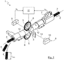
- FIG. 1 shows the device 1 for cutting an empty tube 2 schematically in isometric view.
- FIG. 2 shows a section through the device 1.
- the device 1 according to the invention comprises a cutting device 3 for cutting and / or slotting the empty tube 2 at an axial cutting position P (see. FIG. 2 ).
- the cutting device 3 is designed as a knife with a cutting edge in order to cut the empty tube 2 into individual empty tube pieces 4.
- the cutting device 3 is delivered to the empty tube 2 orthogonal thereto to a feed direction of the empty tube 2 or an axial feed direction Z for cutting in a uniaxial motion.
- a sawing, multi-axis cutting movement is possible, in particular if the cutting device 3 is designed as a saw with a saw blade.
- the apparatus 1 shown in the embodiment serves to cut a "unending" empty pipe 2, for example, unrolled from a roll, for producing individual empty pipe pieces 4 with a predefined length L RES .
- the cutting device 3 can also be designed and usable for any desired cutting, slitting or perforation of the empty tube 2 along the circumference of the empty tube 2.
- the empty tube 2 is executed in the embodiment as a corrugated tube 2, but in principle may have any configuration, in particular be performed smoothly on the outer surfaces.
- the device 1 further comprises two feed wheels 5 for axial positioning of the empty tube 2 on the cutting device 3, wherein the empty tube 2 in the present case is guided between the two feed wheels 5.
- a single feed wheel 5 may be provided.
- the use of at least two feed wheels 5 may be advantageous to provide a uniform and robust guidance of the empty tube 2.
- the feed wheels 5 have an outer toothing 6 adapted to an outer structure of the empty tube 2 or of the corrugated tube, in order to enable a positive guidance of the empty tube 2.
- the feed wheel 5 is thus adapted to the wave structure of the empty tube 2 or of the corrugated tube (see, in particular FIG. 4 ).
- the device 1 further comprises a measuring wheel 7, which is axially spaced apart from the feed wheels 5 along the empty tube 2 and has an axial feed length L (cf. FIG. 4 ) of the empty tube 2 to detect.
- the device 1 further comprises an additional sensor device 8 in order to detect an axial position of the empty tube 2 relative to the cutting device 3.
- the sensor device 8 is designed as an optical sensor device 8 which will be described in more detail below and comprises a photodetector 9 and a light source 10, preferably a laser.
- the device 1 also comprises a control device 11, which is adapted to spend the empty tube 2 on the basis of measurement data u M of the measuring wheel 7 and measurement data u S of the sensor device 8 by driving the feed wheels 5 in the cutting position P.
- a pipe guide 12 which is formed in the embodiment as a hollow cylinder may be provided.
- two pipe guides 12 are provided, which are axially spaced in the region of the cutting position P and thus allow penetration of the cutting device 3.
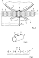
- One of the pipe guides 12 is a schematic isometric view in FIG FIG. 3 shown together with the also schematically indicated cutting device 3.
- FIG. 4 an enlarged section is shown on the cutting position P or on the two feed wheels 5 in the region of the cutting device 3.
- the wave structure of the empty tube 2 or of the corrugated tube and the outer toothing 6 of the feed wheels 5 adapted thereto are easily recognizable.
- the pipe guide is in FIG. 4 not shown.
- the feed wheels 5 along its circumference regularly distributed notches 13 which are arranged in the valleys of the external toothing 6 or formed as part of the valleys.
- the notches 13 are particularly suitable to allow penetration of the cutting device 3.
- the notches 13 represent an advantageous possibility of using the sensor device 8 designed as optical sensor device 8 in the exemplary embodiment for detecting the axial position of the empty tube 2 relative to the cutting device 3.
- the light source 10 or the laser can be aligned on the photodetector 9, that between the light source 10 and the laser and the photodetector 9, a feed wheel 5 is arranged, wherein the feed wheel 5 in response to its rotational or radial position due to its External teeth 6 a light beam 14 on the photodetector 9 either releases or blocks.
- the location to which the light beam 14 is aligned is marked with an "X". Since the feed wheel 5 positively interacts with the empty tube 2 due to its external toothing 6, finally the relative position of wave crests 15 and troughs 16 of the empty tube 2 with respect to the cutting position P or to the cutting device 3 can be detected by the sensor device 8.
- the cutting position P is defined as the axial feed length L +/- determined by means of the measuring wheel 7, a correction term ⁇ L determined on the basis of the sensor device 8 (see illustration in FIG FIG. 4 ).
- the cutting position P is defined in particular on a wave crest 15 of the empty tube 2.
- the cutting of the empty tube 2 is thus initially according to the specification of the length L for the desired empty pipe sections 4, wherein the cutting position P is finally corrected even slightly based on the data of the sensor device 8, namely up to an adjacent wave crest 15, preferably in the axial feed Z following Wellenberg 15.
- the resulting length L RES of an empty pipe section 4 essentially corresponds to the axial feed-in length L, taking into account the external structure of the empty pipe 2.
- the device 1 may further comprise a guide means 17, which is preferably plate-shaped.
- the guide means is designed as a guide plate 17.
- the guide plate 17 directs the empty tube 2, which is formed axially slotted in the embodiment, from.
- the guide plate 17 is formed and arranged to engage in the axial slot 18 of the empty tube 2, as in FIG. 5 shown schematically.
- the pipe guide 12 is formed to receive the guide plate 17 (see. FIG. 2 ).
- any number of guide plates 17 may be provided, in particular a guide plate 17, two guide plates 17 or more guide plates 17.
- the guide plates 17 are arranged as close as possible adjacent to the cutting position P or to the cutting device 3, in particular a stabilization during the To enable cutting.
- the use of at least one guide means, in particular a guide plate 17, and independently of the use of a measuring wheel 7, the additional sensor device 8 and / or the control device 11 may be provided.
- the invention shown in the embodiment also relates to a in FIG. 6 illustrated method for cutting an empty tube 2, after which a control device 11, the empty tube 2 in a first step A by means of at least one feed wheel 5 positioned.
- a measuring wheel 7 axially spaced from the at least one feed wheel 5 along the empty tube 2 detects an axial feed length L of the empty tube 2.
- the control device 11 controls the empty tube 2 on the basis of measured data u M of the measuring wheel 7 and measured data u S of an additional sensor device 8 which detects an axial position of the empty tube 2 relative to the cutting device 3 of the at least one feed wheel 5 spends in the cutting position P.
- the cutting device 3 cut the empty tube 2 to the cutting position P and / or perforate.
- a computer program product with program code means may be provided for carrying out the above-described method when the program is executed on a control device 11 of a device 1 for cutting an empty pipe 2.
Landscapes
- Life Sciences & Earth Sciences (AREA)
- Forests & Forestry (AREA)
- Engineering & Computer Science (AREA)
- Mechanical Engineering (AREA)
- Sawing (AREA)
Priority Applications (1)
| Application Number | Priority Date | Filing Date | Title |
|---|---|---|---|
| PL19166714T PL3552785T3 (pl) | 2018-04-13 | 2019-04-02 | Przyrząd i sposób cięcia pustej rury |
Applications Claiming Priority (1)
| Application Number | Priority Date | Filing Date | Title |
|---|---|---|---|
| DE102018108857.4A DE102018108857A1 (de) | 2018-04-13 | 2018-04-13 | Vorrichtung und Verfahren zum Schneiden eines Leerrohrs |
Publications (2)
| Publication Number | Publication Date |
|---|---|
| EP3552785A1 true EP3552785A1 (fr) | 2019-10-16 |
| EP3552785B1 EP3552785B1 (fr) | 2020-12-30 |
Family
ID=66091897
Family Applications (1)
| Application Number | Title | Priority Date | Filing Date |
|---|---|---|---|
| EP19166714.6A Active EP3552785B1 (fr) | 2018-04-13 | 2019-04-02 | Dispositif et procédé de coupe d'un tube vide |
Country Status (3)
| Country | Link |
|---|---|
| EP (1) | EP3552785B1 (fr) |
| DE (1) | DE102018108857A1 (fr) |
| PL (1) | PL3552785T3 (fr) |
Cited By (2)
| Publication number | Priority date | Publication date | Assignee | Title |
|---|---|---|---|---|
| CN114274214A (zh) * | 2021-12-23 | 2022-04-05 | 广东奋尚生态科技有限公司 | 一种具有计长度装置的高效双壁波纹管切割装置 |
| CN120480425A (zh) * | 2025-06-17 | 2025-08-15 | 安徽理工大学 | 一种适用于多种直径轴向切缝管的自动切割台 |
Families Citing this family (1)
| Publication number | Priority date | Publication date | Assignee | Title |
|---|---|---|---|---|
| CN113352147B (zh) * | 2021-07-15 | 2024-06-07 | 安徽塑茂管道科技有限公司 | 一种大型波纹管制造用切割轮用辅助机构及其使用方法 |
Citations (3)
| Publication number | Priority date | Publication date | Assignee | Title |
|---|---|---|---|---|
| DE29823651U1 (de) * | 1998-03-21 | 1999-11-11 | Metzner, Klaus, 89231 Neu-Ulm | Vorrichtung zum Positionieren von Wellrohrschläuchen |
| JP2004314183A (ja) * | 2003-04-11 | 2004-11-11 | Kodera Electronics Co Ltd | チューブ切断装置 |
| CN201342518Y (zh) * | 2008-12-24 | 2009-11-11 | 广东联塑科技实业有限公司 | 一种波纹管材切割机的切割定位装置 |
-
2018
- 2018-04-13 DE DE102018108857.4A patent/DE102018108857A1/de not_active Withdrawn
-
2019
- 2019-04-02 EP EP19166714.6A patent/EP3552785B1/fr active Active
- 2019-04-02 PL PL19166714T patent/PL3552785T3/pl unknown
Patent Citations (3)
| Publication number | Priority date | Publication date | Assignee | Title |
|---|---|---|---|---|
| DE29823651U1 (de) * | 1998-03-21 | 1999-11-11 | Metzner, Klaus, 89231 Neu-Ulm | Vorrichtung zum Positionieren von Wellrohrschläuchen |
| JP2004314183A (ja) * | 2003-04-11 | 2004-11-11 | Kodera Electronics Co Ltd | チューブ切断装置 |
| CN201342518Y (zh) * | 2008-12-24 | 2009-11-11 | 广东联塑科技实业有限公司 | 一种波纹管材切割机的切割定位装置 |
Cited By (3)
| Publication number | Priority date | Publication date | Assignee | Title |
|---|---|---|---|---|
| CN114274214A (zh) * | 2021-12-23 | 2022-04-05 | 广东奋尚生态科技有限公司 | 一种具有计长度装置的高效双壁波纹管切割装置 |
| CN114274214B (zh) * | 2021-12-23 | 2024-03-22 | 广东奋尚生态科技有限公司 | 一种具有计长度装置的高效双壁波纹管切割装置 |
| CN120480425A (zh) * | 2025-06-17 | 2025-08-15 | 安徽理工大学 | 一种适用于多种直径轴向切缝管的自动切割台 |
Also Published As
| Publication number | Publication date |
|---|---|
| EP3552785B1 (fr) | 2020-12-30 |
| DE102018108857A1 (de) | 2019-10-17 |
| PL3552785T3 (pl) | 2021-07-12 |
Similar Documents
| Publication | Publication Date | Title |
|---|---|---|
| EP2106314B1 (fr) | Dispositif pour couper un tube ondulé | |
| EP2189057A1 (fr) | Procédé de fabrication de tuyaux d'irrigation goutte à goutte | |
| DE2406147A1 (de) | Vorrichtung zum zerschneiden von holzbahnen u.dgl | |
| EP3552785B1 (fr) | Dispositif et procédé de coupe d'un tube vide | |
| DE102014117255B3 (de) | Vermessung von Materialabmessungen | |
| EP3673570B1 (fr) | Système de préparation destiné à fabriquer une tige d'enroulement pour un moteur électrique, et procédé de fabrication d'une tige d'enroulement | |
| EP0944444B1 (fr) | Systeme pour former un tuyau en forme d'helice | |
| EP0622136A1 (fr) | Dispositif pour la fabrication de treillis d'armature pour panneaux en béton | |
| DE102018128684B4 (de) | Vorrichtung zum Schleifen von Sägezähnen sowie ein entsprechendes Verfahren | |
| EP2845664A1 (fr) | Procédé et dispositif de fabrication d'un tuyau ondulé en métal | |
| DE102017120292B4 (de) | Trennvorrichtung für Rohre | |
| DE102006059609B4 (de) | Herstellungsverfahren für Rohre und Walzenstraße zur Durchführung | |
| WO2019158404A1 (fr) | Système destiné au sectionnement en longueur d'un tube | |
| CH620607A5 (en) | Device for the production of helically seamed and perforated tubes | |
| CH639571A5 (de) | Vorrichtung zur kontinuierlichen herstellung von rohren aus spiralfoermig aufgewundenen streifen. | |
| DE19812524A1 (de) | Verfahren und Vorrichtung zum Positionieren von Wellrohrschläuchen | |
| EP3797949B1 (fr) | Dispositif et procédé de perforation d'une bande d'etiquettes | |
| EP0045733B1 (fr) | Dispositif pour enlever la bavure extérieure de tubes soudés longitudinalement | |
| EP1046439B1 (fr) | Rouleau pour tête radiale à rouler des filets | |
| EP3098189A1 (fr) | Dispositif de separation d'une bande de materiau continue dans le sens de transport | |
| DE19807337A1 (de) | Verfahren zum Schneiden von Wellrohren sowie Vorrichtung zur Durchführung des Verfahrens | |
| DE102013019598B4 (de) | Verfahren und Vorrichtung zur Herstellung von Aussparungen in Haltestangen | |
| DE102024102814A1 (de) | Vorrichtung und Verfahren zum Konfektionieren eines Falten aufweisenden Behangmateriales | |
| DE102023101600B4 (de) | Verfahren und maschinelle Anordnung zum Zerteilen eines Restgitters einer trennenden Bearbeitung eines plattenförmigen Werkstücks sowie maschinelle Anlage mit einer derartigen Anordnung | |
| DE102004009222B4 (de) | Multifunktions-Schneidevorrichtung |
Legal Events
| Date | Code | Title | Description |
|---|---|---|---|
| PUAI | Public reference made under article 153(3) epc to a published international application that has entered the european phase |
Free format text: ORIGINAL CODE: 0009012 |
|
| STAA | Information on the status of an ep patent application or granted ep patent |
Free format text: STATUS: THE APPLICATION HAS BEEN PUBLISHED |
|
| AK | Designated contracting states |
Kind code of ref document: A1 Designated state(s): AL AT BE BG CH CY CZ DE DK EE ES FI FR GB GR HR HU IE IS IT LI LT LU LV MC MK MT NL NO PL PT RO RS SE SI SK SM TR |
|
| AX | Request for extension of the european patent |
Extension state: BA ME |
|
| STAA | Information on the status of an ep patent application or granted ep patent |
Free format text: STATUS: REQUEST FOR EXAMINATION WAS MADE |
|
| 17P | Request for examination filed |
Effective date: 20200402 |
|
| RBV | Designated contracting states (corrected) |
Designated state(s): AL AT BE BG CH CY CZ DE DK EE ES FI FR GB GR HR HU IE IS IT LI LT LU LV MC MK MT NL NO PL PT RO RS SE SI SK SM TR |
|
| GRAP | Despatch of communication of intention to grant a patent |
Free format text: ORIGINAL CODE: EPIDOSNIGR1 |
|
| STAA | Information on the status of an ep patent application or granted ep patent |
Free format text: STATUS: GRANT OF PATENT IS INTENDED |
|
| RIC1 | Information provided on ipc code assigned before grant |
Ipc: B26D 3/16 20060101AFI20200723BHEP |
|
| INTG | Intention to grant announced |
Effective date: 20200813 |
|
| GRAS | Grant fee paid |
Free format text: ORIGINAL CODE: EPIDOSNIGR3 |
|
| GRAA | (expected) grant |
Free format text: ORIGINAL CODE: 0009210 |
|
| STAA | Information on the status of an ep patent application or granted ep patent |
Free format text: STATUS: THE PATENT HAS BEEN GRANTED |
|
| AK | Designated contracting states |
Kind code of ref document: B1 Designated state(s): AL AT BE BG CH CY CZ DE DK EE ES FI FR GB GR HR HU IE IS IT LI LT LU LV MC MK MT NL NO PL PT RO RS SE SI SK SM TR |
|
| REG | Reference to a national code |
Ref country code: GB Ref legal event code: FG4D Free format text: NOT ENGLISH |
|
| REG | Reference to a national code |
Ref country code: AT Ref legal event code: REF Ref document number: 1349470 Country of ref document: AT Kind code of ref document: T Effective date: 20210115 |
|
| REG | Reference to a national code |
Ref country code: DE Ref legal event code: R096 Ref document number: 502019000599 Country of ref document: DE |
|
| REG | Reference to a national code |
Ref country code: IE Ref legal event code: FG4D Free format text: LANGUAGE OF EP DOCUMENT: GERMAN |
|
| REG | Reference to a national code |
Ref country code: RO Ref legal event code: EPE |
|
| REG | Reference to a national code |
Ref country code: CH Ref legal event code: NV Representative=s name: COSMOVICI INTELLECTUAL PROPERTY SARL, CH |
|
| PG25 | Lapsed in a contracting state [announced via postgrant information from national office to epo] |
Ref country code: RS Free format text: LAPSE BECAUSE OF FAILURE TO SUBMIT A TRANSLATION OF THE DESCRIPTION OR TO PAY THE FEE WITHIN THE PRESCRIBED TIME-LIMIT Effective date: 20201230 Ref country code: FI Free format text: LAPSE BECAUSE OF FAILURE TO SUBMIT A TRANSLATION OF THE DESCRIPTION OR TO PAY THE FEE WITHIN THE PRESCRIBED TIME-LIMIT Effective date: 20201230 Ref country code: NO Free format text: LAPSE BECAUSE OF FAILURE TO SUBMIT A TRANSLATION OF THE DESCRIPTION OR TO PAY THE FEE WITHIN THE PRESCRIBED TIME-LIMIT Effective date: 20210330 Ref country code: GR Free format text: LAPSE BECAUSE OF FAILURE TO SUBMIT A TRANSLATION OF THE DESCRIPTION OR TO PAY THE FEE WITHIN THE PRESCRIBED TIME-LIMIT Effective date: 20210331 |
|
| PG25 | Lapsed in a contracting state [announced via postgrant information from national office to epo] |
Ref country code: BG Free format text: LAPSE BECAUSE OF FAILURE TO SUBMIT A TRANSLATION OF THE DESCRIPTION OR TO PAY THE FEE WITHIN THE PRESCRIBED TIME-LIMIT Effective date: 20210330 Ref country code: SE Free format text: LAPSE BECAUSE OF FAILURE TO SUBMIT A TRANSLATION OF THE DESCRIPTION OR TO PAY THE FEE WITHIN THE PRESCRIBED TIME-LIMIT Effective date: 20201230 Ref country code: LV Free format text: LAPSE BECAUSE OF FAILURE TO SUBMIT A TRANSLATION OF THE DESCRIPTION OR TO PAY THE FEE WITHIN THE PRESCRIBED TIME-LIMIT Effective date: 20201230 |
|
| REG | Reference to a national code |
Ref country code: NL Ref legal event code: MP Effective date: 20201230 |
|
| PG25 | Lapsed in a contracting state [announced via postgrant information from national office to epo] |
Ref country code: HR Free format text: LAPSE BECAUSE OF FAILURE TO SUBMIT A TRANSLATION OF THE DESCRIPTION OR TO PAY THE FEE WITHIN THE PRESCRIBED TIME-LIMIT Effective date: 20201230 |
|
| REG | Reference to a national code |
Ref country code: LT Ref legal event code: MG9D |
|
| PG25 | Lapsed in a contracting state [announced via postgrant information from national office to epo] |
Ref country code: PT Free format text: LAPSE BECAUSE OF FAILURE TO SUBMIT A TRANSLATION OF THE DESCRIPTION OR TO PAY THE FEE WITHIN THE PRESCRIBED TIME-LIMIT Effective date: 20210430 Ref country code: LT Free format text: LAPSE BECAUSE OF FAILURE TO SUBMIT A TRANSLATION OF THE DESCRIPTION OR TO PAY THE FEE WITHIN THE PRESCRIBED TIME-LIMIT Effective date: 20201230 Ref country code: CZ Free format text: LAPSE BECAUSE OF FAILURE TO SUBMIT A TRANSLATION OF THE DESCRIPTION OR TO PAY THE FEE WITHIN THE PRESCRIBED TIME-LIMIT Effective date: 20201230 Ref country code: SK Free format text: LAPSE BECAUSE OF FAILURE TO SUBMIT A TRANSLATION OF THE DESCRIPTION OR TO PAY THE FEE WITHIN THE PRESCRIBED TIME-LIMIT Effective date: 20201230 Ref country code: EE Free format text: LAPSE BECAUSE OF FAILURE TO SUBMIT A TRANSLATION OF THE DESCRIPTION OR TO PAY THE FEE WITHIN THE PRESCRIBED TIME-LIMIT Effective date: 20201230 |
|
| PG25 | Lapsed in a contracting state [announced via postgrant information from national office to epo] |
Ref country code: IS Free format text: LAPSE BECAUSE OF FAILURE TO SUBMIT A TRANSLATION OF THE DESCRIPTION OR TO PAY THE FEE WITHIN THE PRESCRIBED TIME-LIMIT Effective date: 20210430 |
|
| REG | Reference to a national code |
Ref country code: DE Ref legal event code: R097 Ref document number: 502019000599 Country of ref document: DE |
|
| PG25 | Lapsed in a contracting state [announced via postgrant information from national office to epo] |
Ref country code: AL Free format text: LAPSE BECAUSE OF FAILURE TO SUBMIT A TRANSLATION OF THE DESCRIPTION OR TO PAY THE FEE WITHIN THE PRESCRIBED TIME-LIMIT Effective date: 20201230 |
|
| PLBE | No opposition filed within time limit |
Free format text: ORIGINAL CODE: 0009261 |
|
| STAA | Information on the status of an ep patent application or granted ep patent |
Free format text: STATUS: NO OPPOSITION FILED WITHIN TIME LIMIT |
|
| PG25 | Lapsed in a contracting state [announced via postgrant information from national office to epo] |
Ref country code: MC Free format text: LAPSE BECAUSE OF FAILURE TO SUBMIT A TRANSLATION OF THE DESCRIPTION OR TO PAY THE FEE WITHIN THE PRESCRIBED TIME-LIMIT Effective date: 20201230 Ref country code: DK Free format text: LAPSE BECAUSE OF FAILURE TO SUBMIT A TRANSLATION OF THE DESCRIPTION OR TO PAY THE FEE WITHIN THE PRESCRIBED TIME-LIMIT Effective date: 20201230 |
|
| 26N | No opposition filed |
Effective date: 20211001 |
|
| PG25 | Lapsed in a contracting state [announced via postgrant information from national office to epo] |
Ref country code: LU Free format text: LAPSE BECAUSE OF NON-PAYMENT OF DUE FEES Effective date: 20210402 |
|
| REG | Reference to a national code |
Ref country code: BE Ref legal event code: MM Effective date: 20210430 |
|
| PG25 | Lapsed in a contracting state [announced via postgrant information from national office to epo] |
Ref country code: FR Free format text: LAPSE BECAUSE OF NON-PAYMENT OF DUE FEES Effective date: 20210430 Ref country code: ES Free format text: LAPSE BECAUSE OF FAILURE TO SUBMIT A TRANSLATION OF THE DESCRIPTION OR TO PAY THE FEE WITHIN THE PRESCRIBED TIME-LIMIT Effective date: 20201230 |
|
| PG25 | Lapsed in a contracting state [announced via postgrant information from national office to epo] |
Ref country code: SI Free format text: LAPSE BECAUSE OF FAILURE TO SUBMIT A TRANSLATION OF THE DESCRIPTION OR TO PAY THE FEE WITHIN THE PRESCRIBED TIME-LIMIT Effective date: 20201230 |
|
| PG25 | Lapsed in a contracting state [announced via postgrant information from national office to epo] |
Ref country code: IE Free format text: LAPSE BECAUSE OF NON-PAYMENT OF DUE FEES Effective date: 20210402 |
|
| PG25 | Lapsed in a contracting state [announced via postgrant information from national office to epo] |
Ref country code: IS Free format text: LAPSE BECAUSE OF FAILURE TO SUBMIT A TRANSLATION OF THE DESCRIPTION OR TO PAY THE FEE WITHIN THE PRESCRIBED TIME-LIMIT Effective date: 20210430 |
|
| PG25 | Lapsed in a contracting state [announced via postgrant information from national office to epo] |
Ref country code: BE Free format text: LAPSE BECAUSE OF NON-PAYMENT OF DUE FEES Effective date: 20210430 |
|
| P01 | Opt-out of the competence of the unified patent court (upc) registered |
Effective date: 20230426 |
|
| PG25 | Lapsed in a contracting state [announced via postgrant information from national office to epo] |
Ref country code: NL Free format text: LAPSE BECAUSE OF NON-PAYMENT OF DUE FEES Effective date: 20201230 Ref country code: CY Free format text: LAPSE BECAUSE OF FAILURE TO SUBMIT A TRANSLATION OF THE DESCRIPTION OR TO PAY THE FEE WITHIN THE PRESCRIBED TIME-LIMIT Effective date: 20201230 |
|
| PG25 | Lapsed in a contracting state [announced via postgrant information from national office to epo] |
Ref country code: SM Free format text: LAPSE BECAUSE OF FAILURE TO SUBMIT A TRANSLATION OF THE DESCRIPTION OR TO PAY THE FEE WITHIN THE PRESCRIBED TIME-LIMIT Effective date: 20201230 Ref country code: HU Free format text: LAPSE BECAUSE OF FAILURE TO SUBMIT A TRANSLATION OF THE DESCRIPTION OR TO PAY THE FEE WITHIN THE PRESCRIBED TIME-LIMIT; INVALID AB INITIO Effective date: 20190402 |
|
| GBPC | Gb: european patent ceased through non-payment of renewal fee |
Effective date: 20230402 |
|
| PG25 | Lapsed in a contracting state [announced via postgrant information from national office to epo] |
Ref country code: GB Free format text: LAPSE BECAUSE OF NON-PAYMENT OF DUE FEES Effective date: 20230402 |
|
| PG25 | Lapsed in a contracting state [announced via postgrant information from national office to epo] |
Ref country code: GB Free format text: LAPSE BECAUSE OF NON-PAYMENT OF DUE FEES Effective date: 20230402 |
|
| PG25 | Lapsed in a contracting state [announced via postgrant information from national office to epo] |
Ref country code: MK Free format text: LAPSE BECAUSE OF FAILURE TO SUBMIT A TRANSLATION OF THE DESCRIPTION OR TO PAY THE FEE WITHIN THE PRESCRIBED TIME-LIMIT Effective date: 20201230 |
|
| PG25 | Lapsed in a contracting state [announced via postgrant information from national office to epo] |
Ref country code: MT Free format text: LAPSE BECAUSE OF FAILURE TO SUBMIT A TRANSLATION OF THE DESCRIPTION OR TO PAY THE FEE WITHIN THE PRESCRIBED TIME-LIMIT Effective date: 20201230 |
|
| PGFP | Annual fee paid to national office [announced via postgrant information from national office to epo] |
Ref country code: RO Payment date: 20250327 Year of fee payment: 7 |
|
| PGFP | Annual fee paid to national office [announced via postgrant information from national office to epo] |
Ref country code: PL Payment date: 20250320 Year of fee payment: 7 |
|
| REG | Reference to a national code |
Ref country code: AT Ref legal event code: MM01 Ref document number: 1349470 Country of ref document: AT Kind code of ref document: T Effective date: 20240402 |
|
| PGFP | Annual fee paid to national office [announced via postgrant information from national office to epo] |
Ref country code: DE Payment date: 20250425 Year of fee payment: 7 |
|
| PGFP | Annual fee paid to national office [announced via postgrant information from national office to epo] |
Ref country code: IT Payment date: 20250430 Year of fee payment: 7 |
|
| PGFP | Annual fee paid to national office [announced via postgrant information from national office to epo] |
Ref country code: CH Payment date: 20250501 Year of fee payment: 7 |
|
| PG25 | Lapsed in a contracting state [announced via postgrant information from national office to epo] |
Ref country code: AT Free format text: LAPSE BECAUSE OF NON-PAYMENT OF DUE FEES Effective date: 20240402 |
|
| PG25 | Lapsed in a contracting state [announced via postgrant information from national office to epo] |
Ref country code: TR Free format text: LAPSE BECAUSE OF FAILURE TO SUBMIT A TRANSLATION OF THE DESCRIPTION OR TO PAY THE FEE WITHIN THE PRESCRIBED TIME-LIMIT Effective date: 20201230 |