EP3552785A1 - Device and method for cutting an empty tube - Google Patents
Device and method for cutting an empty tube Download PDFInfo
- Publication number
- EP3552785A1 EP3552785A1 EP19166714.6A EP19166714A EP3552785A1 EP 3552785 A1 EP3552785 A1 EP 3552785A1 EP 19166714 A EP19166714 A EP 19166714A EP 3552785 A1 EP3552785 A1 EP 3552785A1
- Authority
- EP
- European Patent Office
- Prior art keywords
- cutting
- empty tube
- axial
- feed
- empty
- Prior art date
- Legal status (The legal status is an assumption and is not a legal conclusion. Google has not performed a legal analysis and makes no representation as to the accuracy of the status listed.)
- Granted
Links
Images

Classifications
-
- B—PERFORMING OPERATIONS; TRANSPORTING
- B26—HAND CUTTING TOOLS; CUTTING; SEVERING
- B26D—CUTTING; DETAILS COMMON TO MACHINES FOR PERFORATING, PUNCHING, CUTTING-OUT, STAMPING-OUT OR SEVERING
- B26D3/00—Cutting work characterised by the nature of the cut made; Apparatus therefor
- B26D3/16—Cutting rods or tubes transversely
-
- B—PERFORMING OPERATIONS; TRANSPORTING
- B26—HAND CUTTING TOOLS; CUTTING; SEVERING
- B26D—CUTTING; DETAILS COMMON TO MACHINES FOR PERFORATING, PUNCHING, CUTTING-OUT, STAMPING-OUT OR SEVERING
- B26D7/00—Details of apparatus for cutting, cutting-out, stamping-out, punching, perforating, or severing by means other than cutting
- B26D7/01—Means for holding or positioning work
- B26D2007/013—Means for holding or positioning work the work being tubes, rods or logs
-
- B—PERFORMING OPERATIONS; TRANSPORTING
- B26—HAND CUTTING TOOLS; CUTTING; SEVERING
- B26D—CUTTING; DETAILS COMMON TO MACHINES FOR PERFORATING, PUNCHING, CUTTING-OUT, STAMPING-OUT OR SEVERING
- B26D5/00—Arrangements for operating and controlling machines or devices for cutting, cutting-out, stamping-out, punching, perforating, or severing by means other than cutting
- B26D5/20—Arrangements for operating and controlling machines or devices for cutting, cutting-out, stamping-out, punching, perforating, or severing by means other than cutting with interrelated action between the cutting member and work feed
- B26D5/22—Arrangements for operating and controlling machines or devices for cutting, cutting-out, stamping-out, punching, perforating, or severing by means other than cutting with interrelated action between the cutting member and work feed having the cutting member and work feed mechanically connected
- B26D5/24—Arrangements for operating and controlling machines or devices for cutting, cutting-out, stamping-out, punching, perforating, or severing by means other than cutting with interrelated action between the cutting member and work feed having the cutting member and work feed mechanically connected including a metering device
Definitions
- the invention relates to a device for cutting a conduit according to the preamble of claim 1.
- the invention further relates to a method for cutting an empty tube according to the preamble of claim 12.
- the invention also relates to a computer program product.
- Methods and apparatus for cutting conduits are used in practice to cut conduits of any kind into individual conduits of defined length.
- the empty tube is usually unwound from a roll and fed to the corresponding device as a blank of a somewhat "infinite" length. It depends on the accuracy of the cut and for economic reasons also on the speed or throughput of the device.
- the empty tube is first positioned axially by means of a feed wheel on a cutting device and then severed from this at a cutting position. It has been shown that an exact positioning of the empty tube on the cutting device or ensuring an exact cutting position for many applications, in particular while maintaining a high throughput, with the conventional devices is possible only with considerable effort.
- the present invention is therefore based on the object to provide an apparatus and a method for cutting an empty tube, wherein the disadvantages of the prior art are avoided and in particular a sufficiently accurate axial positioning of the empty tube is made possible on the cutting device.
- the device according to the invention for cutting an empty tube comprises a cutting device for cutting and / or cutting the empty tube at an axial cutting position, at least one feed wheel for the axial positioning of the empty tube at the cutting device, and a control device.
- this can be a rigid or flexible pipe, preferably of plastic or metal.
- Such conduits for example, for the installation of other pipes, z.
- the conduit according to the invention can also be suitable for the direct transport of solids, liquids and / or gases. On the subsequent use of the empty pipe it does not matter in the context of the invention.
- one of the at least one feed wheel along the empty tube axially spaced measuring wheel is provided to detect an axial feed length of the empty tube. Furthermore, an additional sensor device is provided to detect an axial position of the empty tube relative to the cutting device. The control device is set up to use the empty tube on the basis of measured data of the measuring wheel and measured data of the sensor device by driving the at least one feed wheel into the cutting position.
- the axial infeed length of the empty tube which is detected by means of the measuring wheel, corresponds essentially to the length of the individual cut-length empty tube pieces resulting from a cutting of the empty tube.
- the axial position of the empty tube relative to the cutting device may, for example, be an axial position of a partial section that repeats axially along the empty tube.
- the actual cutting position can be based on the measurement data of the measuring wheel and the sensor device.
- the inventive use of a measuring wheel in combination with the additional sensor device allows extremely accurate positioning of the empty tube on the cutting device.
- an absolute position or an axial feed length which can be determined by means of the measuring wheel, is combined with a relative position of the empty tube (or a section of the empty tube). This can ensure that a predetermined length of the cut or cut empty pipe sections and / or a predetermined distance between slots or perforations of the empty pipe are maintained, at the same time an exact alignment of relative reference points or sections of the empty pipe lead to an optimal cutting result on the cutting device.
- the empty tube is designed as a corrugated tube and / or corrugated tube.
- the cutting of corrugated pipes and corrugated hoses is particularly complex due to their wavy outer structure, which is why the invention can be particularly suitable for the exact cutting of corrugated pipes and / or corrugated hoses.
- the sensor device may advantageously be designed or usable on the cutting device for aligning wave crests, wave troughs and / or transitions between wave crests and wave troughs.
- the invention may also be advantageous for cutting to length and / or for cutting empty tubes with smooth or other external structure.
- the cutting device has a knife with a cutting edge and / or a saw with a saw blade.
- a knife is provided with a cutting edge, since the mechanical requirements for the device can then be reduced. For example, when cutting with a knife usually occurs no chip that would have to be dissipated. Furthermore, a cutting motion based on a knife with a blade can be made mechanically easier than a "sawing" motion that would be required in a saw with a saw blade.
- the improvement according to the invention regarding the positioning of the empty tube on the cutting device can basically have a positive effect on all types of cutting device.
- the cutting device is designed to cut the empty tube orthogonal to an axial feed direction at the cutting position and / or cutting, z. B. at least partially perforate along the circumference of the empty tube.
- the delivery of a knife with a cutting edge in a uniaxial, incisive or "stabbing" movement can take place orthogonal to the axial feed direction of the empty tube.
- two feed wheels may be provided, between which the empty tube is guided.
- a particularly uniform delivery of the empty tube can be made possible.
- a single feed wheel may already be sufficient to allow axial delivery.
- a combination of a feed wheel and a non-driven, but freely rotatable, preferably the feed wheel opposite guide wheel is possible.
- the at least one feed wheel has an outer toothing adapted to the outer structure of the empty tube, preferably to a wave structure, in order to enable a positive guidance of the empty tube.
- the axial delivery of the empty tube can preferably take place in the manner of a mutual gear engagement between the at least one feed wheel and an externally toothed empty tube.
- the feed generated by the at least one feed wheel can thereby be made even more accurate.
- the at least one feed wheel has notches distributed regularly along its circumference, preferably in the valleys of an external toothing.
- a feed wheel with indentations may be advantageous since the cutting device, inter alia the cutting edge of a knife, can penetrate into the feed wheel during the cutting of the empty pipe into the free space provided by the notches , Furthermore, the notches in the at least one feed wheel can advantageously be used for detecting the rotary position of the feed wheel by means of the sensor device, for example to indirectly close to a relative position of the empty tube, in particular if the at least one feed wheel has an outer toothing for engagement in an outer structure of the empty tube has and the empty tube thus leads positively.
- the cutting position is defined as the axial feed length detected by means of the measuring wheel +/- a correction term determined on the basis of the sensor device.
- first of all the desired axial feed length can be set, after which the correction term is determined by the sensor device based on the axial position of the empty tube relative to the cutting device in order to achieve an optimum cutting result.
- the cutting position is defined on a corrugation peak of the corrugated tube and / or the corrugated tube.
- the axial position of the empty tube with respect to a relative orientation of the outer structure of the empty tube still be slightly corrected to the final To achieve cutting position.
- the empty tube can be moved further (or moved back) in the axial direction until, for example, a wave crest of the corrugated tube and / or corrugated tube is positioned on the cutting device such that the cutting position lies on the crest (or alternatively in the trough or at a transition between Wellenberg and Wellental).
- the shaft mountain closest to the axial positioning of the empty tube according to the desired axial infeed length or another suitable section of the empty tube or of the corrugated tube or of the corrugated tube is used as the cutting position.
- the sensor device is designed as an optical sensor device, comprising a photodetector and a light source, preferably a laser.
- an optical sensor device can advantageously be used to detect the relative position of the empty tube with respect to the cutting device.
- the optical sensor device can, for example, the position of the empty tube on the basis of its outer structure directly or by detecting the rotational position of the feed wheel determine indirectly, for example by detecting the external teeth of the at least one feed wheel.
- the sensor device is preferably arranged at the same axial "height" as the cutting device. That is, in a design of the sensor device with a light source of the light beam, preferably a laser beam in the plane of the cutting edge of the cutting device, preferably above or below the cutting edge.
- the sensor device detects the rotary position of the at least one feed wheel.
- the sensor device can be positioned in such a way that, for example, a laser beam passes through it as a function of the rotational position of the feed wheel and, for example, impinges on a photodetector or the laser beam is blocked by the feed wheel.
- suitable recesses, recesses or indentations may be provided in the feed wheel, so that, depending on the rotational position of the feed wheel cyclically alternately shows that the laser beam can penetrate through the feed wheel or is blocked by this.
- the feed wheel has an external toothing, which is composed of protruding teeth and intermediate valleys. It can be provided that the teeth of the feed wheel block the laser beam, while the valleys between the teeth allow the laser beam to pass through the feed wheel.
- the valleys may preferably be formed correspondingly pronounced and / or additional indentations may be provided, which preferably extend further in the direction of the center axis of the feed wheel and thus provide suitable recesses so that a laser beam can pass through.
- the external toothing of the feed wheel is designed such that the teeth of the feed wheel in the valleys of a corrugated tube or a corrugated tube engage to transport the corrugated tube or the corrugated tube in the feed direction.
- the wave crests of the corrugated tube or the corrugated tube between the teeth of the feed wheel are designed such that the teeth of the feed wheel in the valleys of a corrugated tube or a corrugated tube engage to transport the corrugated tube or the corrugated tube in the feed direction.
- the sensor device preferably the laser
- the laser beam penetrates the feed wheel in the region of the valley of the outer toothing of the feed wheel or a preferably radially arranged below indentation, it is automatically ensured that a wave crest of the corrugated pipe or the corrugated tube, which, as shown, is arranged between the teeth of the external toothing, located in the cutting position.
- At least one guide means may be provided, wherein the at least one guide means is formed and arranged to engage in an axial slot of an axially slotted empty tube such that the guide means spends the axial slot in the region of the cutting position in a defined orientation.
- the guide means may be advantageous to arrange the guide means as close as possible to the at least one feed wheel in order to enable a stable guidance or delivery of the empty tube to the cutting device.
- the guide means is preferably flat or plate-shaped. Preferably, it is a guide plate.
- the guide means preferably has an axial length which corresponds to at least twice the diameter of the empty tube.
- a pipe guide can be provided.
- the pipe guide can be designed in particular as a hollow cylinder whose inner diameter corresponds to the outer diameter of the empty pipe in order to allow the most accurate axial guidance of the empty pipe.
- the pipe guide may be formed in one or more parts, for example, be formed from two hollow cylinders. It can also be provided several pipe guides, for example, two pipe guides, preferably in coaxial, axially offset arrangement. In particular, it can be provided that the pipe guide in the region of the cutting device and / or the at least one feed wheel and / or the measuring wheel provides access to the empty pipe.
- the invention also relates to a method for cutting an empty tube, after which a control device positions the empty tube by means of at least one feed wheel at a cutting position on a cutting device and then the cutting device cuts and / or cuts the empty tube at the cutting position. It is provided that one of the at least one feed wheel along the empty tube axially spaced measuring wheel detects an axial feed length of the empty tube, wherein an additional sensor device detects an axial position of the empty tube relative to the cutting device, and wherein the control device, the empty tube based on measurement data of the measuring wheel and measuring data of the sensor device by driving the at least one feed wheel spends in the cutting position.
- the axial position of the empty tube is detected relative to the cutting device by means of the sensor device by a light source, preferably a laser, is aligned with a photodetector, wherein between the light source and the photodetector, the at least one feed wheel is arranged and depending on the rotational position of the feed wheel a light beam to the photodetector either releases or blocks.
- a light source preferably a laser
- the laser can pass through notches or the outer toothing arranged distributed regularly along the circumference of the feed wheel, the position of the empty tube being detected indirectly relative to the cutting device, in particular in the case of a positive guidance of the empty tube.
- At least one guide means is provided, which is designed and arranged such that during the advancing movement of the empty tube, the guide means engages in an axial slot of an axially slotted empty tube in order to align the axial slot in the area of the cutting position ,
- the invention also relates to a computer program product with program code means for carrying out a method according to the above, when the program is executed on a control device of an apparatus for cutting an empty pipe.
- the control device can be designed as a microprocessor. Instead of a microprocessor, any further device for implementing the control device can be provided, for example one or more arrangements of discrete electrical components on a printed circuit board, a programmable logic controller (PLC), an application-specific integrated circuit (ASIC) or another programmable circuit, for example a Field Programmable Gate Array (FPGA), a Programmable Logic Array (PLA), and / or a commercially available computer.
- PLC programmable logic controller
- ASIC application-specific integrated circuit
- FPGA Field Programmable Gate Array
- PLA Programmable Logic Array
- the second invention relates to a device for cutting an empty tube, comprising a cutting device for cutting and / or cutting the empty tube at an axial cutting position and at least one feed wheel for the axial positioning of the empty tube on the cutting device.
- the second invention is characterized in that at least one guide means is provided, wherein the at least one guide means is arranged and arranged to engage in an axial slot of an axially slotted empty tube such that the guide means spends the axial slot in the region of the cutting position in a defined orientation, while the empty tube moves in the feed direction.
- the guide means is preferably flat or plate-shaped and particularly preferably designed as a guide plate.
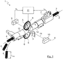
- FIG. 1 shows the device 1 for cutting an empty tube 2 schematically in isometric view.
- FIG. 2 shows a section through the device 1.
- the device 1 according to the invention comprises a cutting device 3 for cutting and / or slotting the empty tube 2 at an axial cutting position P (see. FIG. 2 ).
- the cutting device 3 is designed as a knife with a cutting edge in order to cut the empty tube 2 into individual empty tube pieces 4.
- the cutting device 3 is delivered to the empty tube 2 orthogonal thereto to a feed direction of the empty tube 2 or an axial feed direction Z for cutting in a uniaxial motion.
- a sawing, multi-axis cutting movement is possible, in particular if the cutting device 3 is designed as a saw with a saw blade.
- the apparatus 1 shown in the embodiment serves to cut a "unending" empty pipe 2, for example, unrolled from a roll, for producing individual empty pipe pieces 4 with a predefined length L RES .
- the cutting device 3 can also be designed and usable for any desired cutting, slitting or perforation of the empty tube 2 along the circumference of the empty tube 2.
- the empty tube 2 is executed in the embodiment as a corrugated tube 2, but in principle may have any configuration, in particular be performed smoothly on the outer surfaces.
- the device 1 further comprises two feed wheels 5 for axial positioning of the empty tube 2 on the cutting device 3, wherein the empty tube 2 in the present case is guided between the two feed wheels 5.
- a single feed wheel 5 may be provided.
- the use of at least two feed wheels 5 may be advantageous to provide a uniform and robust guidance of the empty tube 2.
- the feed wheels 5 have an outer toothing 6 adapted to an outer structure of the empty tube 2 or of the corrugated tube, in order to enable a positive guidance of the empty tube 2.
- the feed wheel 5 is thus adapted to the wave structure of the empty tube 2 or of the corrugated tube (see, in particular FIG. 4 ).
- the device 1 further comprises a measuring wheel 7, which is axially spaced apart from the feed wheels 5 along the empty tube 2 and has an axial feed length L (cf. FIG. 4 ) of the empty tube 2 to detect.
- the device 1 further comprises an additional sensor device 8 in order to detect an axial position of the empty tube 2 relative to the cutting device 3.
- the sensor device 8 is designed as an optical sensor device 8 which will be described in more detail below and comprises a photodetector 9 and a light source 10, preferably a laser.
- the device 1 also comprises a control device 11, which is adapted to spend the empty tube 2 on the basis of measurement data u M of the measuring wheel 7 and measurement data u S of the sensor device 8 by driving the feed wheels 5 in the cutting position P.
- a pipe guide 12 which is formed in the embodiment as a hollow cylinder may be provided.
- two pipe guides 12 are provided, which are axially spaced in the region of the cutting position P and thus allow penetration of the cutting device 3.
- One of the pipe guides 12 is a schematic isometric view in FIG FIG. 3 shown together with the also schematically indicated cutting device 3.
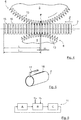
- FIG. 4 an enlarged section is shown on the cutting position P or on the two feed wheels 5 in the region of the cutting device 3.
- the wave structure of the empty tube 2 or of the corrugated tube and the outer toothing 6 of the feed wheels 5 adapted thereto are easily recognizable.
- the pipe guide is in FIG. 4 not shown.
- the feed wheels 5 along its circumference regularly distributed notches 13 which are arranged in the valleys of the external toothing 6 or formed as part of the valleys.
- the notches 13 are particularly suitable to allow penetration of the cutting device 3.
- the notches 13 represent an advantageous possibility of using the sensor device 8 designed as optical sensor device 8 in the exemplary embodiment for detecting the axial position of the empty tube 2 relative to the cutting device 3.
- the light source 10 or the laser can be aligned on the photodetector 9, that between the light source 10 and the laser and the photodetector 9, a feed wheel 5 is arranged, wherein the feed wheel 5 in response to its rotational or radial position due to its External teeth 6 a light beam 14 on the photodetector 9 either releases or blocks.
- the location to which the light beam 14 is aligned is marked with an "X". Since the feed wheel 5 positively interacts with the empty tube 2 due to its external toothing 6, finally the relative position of wave crests 15 and troughs 16 of the empty tube 2 with respect to the cutting position P or to the cutting device 3 can be detected by the sensor device 8.
- the cutting position P is defined as the axial feed length L +/- determined by means of the measuring wheel 7, a correction term ⁇ L determined on the basis of the sensor device 8 (see illustration in FIG FIG. 4 ).
- the cutting position P is defined in particular on a wave crest 15 of the empty tube 2.
- the cutting of the empty tube 2 is thus initially according to the specification of the length L for the desired empty pipe sections 4, wherein the cutting position P is finally corrected even slightly based on the data of the sensor device 8, namely up to an adjacent wave crest 15, preferably in the axial feed Z following Wellenberg 15.
- the resulting length L RES of an empty pipe section 4 essentially corresponds to the axial feed-in length L, taking into account the external structure of the empty pipe 2.
- the device 1 may further comprise a guide means 17, which is preferably plate-shaped.
- the guide means is designed as a guide plate 17.
- the guide plate 17 directs the empty tube 2, which is formed axially slotted in the embodiment, from.
- the guide plate 17 is formed and arranged to engage in the axial slot 18 of the empty tube 2, as in FIG. 5 shown schematically.
- the pipe guide 12 is formed to receive the guide plate 17 (see. FIG. 2 ).
- any number of guide plates 17 may be provided, in particular a guide plate 17, two guide plates 17 or more guide plates 17.
- the guide plates 17 are arranged as close as possible adjacent to the cutting position P or to the cutting device 3, in particular a stabilization during the To enable cutting.
- the use of at least one guide means, in particular a guide plate 17, and independently of the use of a measuring wheel 7, the additional sensor device 8 and / or the control device 11 may be provided.
- the invention shown in the embodiment also relates to a in FIG. 6 illustrated method for cutting an empty tube 2, after which a control device 11, the empty tube 2 in a first step A by means of at least one feed wheel 5 positioned.
- a measuring wheel 7 axially spaced from the at least one feed wheel 5 along the empty tube 2 detects an axial feed length L of the empty tube 2.
- the control device 11 controls the empty tube 2 on the basis of measured data u M of the measuring wheel 7 and measured data u S of an additional sensor device 8 which detects an axial position of the empty tube 2 relative to the cutting device 3 of the at least one feed wheel 5 spends in the cutting position P.
- the cutting device 3 cut the empty tube 2 to the cutting position P and / or perforate.
- a computer program product with program code means may be provided for carrying out the above-described method when the program is executed on a control device 11 of a device 1 for cutting an empty pipe 2.
Landscapes
- Life Sciences & Earth Sciences (AREA)
- Forests & Forestry (AREA)
- Engineering & Computer Science (AREA)
- Mechanical Engineering (AREA)
- Sawing (AREA)
Abstract
Die Erfindung betrifft eine Vorrichtung (1) zum Schneiden eines Leerrohrs (2), umfassend eine Schneideeinrichtung (3) zum Ablängen und/oder zum Einschneiden des Leerrohrs (2) an einer axialen Schneidposition (P), wenigstens ein Vorschubrad (5) zur axialen Positionierung des Leerrohrs (2) an der Schneideeinrichtung (3), sowie eine Steuereinrichtung (11). Es ist ein von dem wenigstens einen Vorschubrad (5) entlang des Leerrohrs (2) axial beabstandetes Messrad (7) vorgesehen, um eine axiale Zustelllänge (L) des Leerrohrs (2) zu erfassen, wobei eine zusätzliche Sensoreinrichtung (8) vorgesehen ist, um eine axiale Position des Leerrohrs (2) relativ zu der Schneideeinrichtung (3) zu erfassen, und wobei die Steuereinrichtung (11) eingerichtet ist, um das Leerrohr (2) anhand von Messdaten (uM) des Messrades (7) und Messdaten (uS) der Sensoreinrichtung (8) durch Ansteuern des wenigstens einen Vorschubrades (5) in die Schneidposition (P) zu verbringen.
Description
Die Erfindung betrifft eine Vorrichtung zum Schneiden eines Leerrohrs gemäß dem Oberbegriff von Anspruch 1.The invention relates to a device for cutting a conduit according to the preamble of
Die Erfindung betrifft ferner ein Verfahren zum Schneiden eines Leerrohrs gemäß dem Oberbegriff des Anspruchs 12.The invention further relates to a method for cutting an empty tube according to the preamble of
Die Erfindung betrifft außerdem ein Computerprogrammprodukt.The invention also relates to a computer program product.
Verfahren und Vorrichtungen zum Schneiden von Leerrohren werden in der Praxis verwendet, um Leerrohre beliebiger Art in einzelne Leerrohrstücke mit definierter Länge zuzuschneiden. Das Leerrohr wird hierfür meist von einer Rolle abgewickelt und der entsprechenden Vorrichtung als Rohling mit gewissermaßen "unendlicher" Länge zugeführt. Dabei kommt es auf die Genauigkeit der Ablängung und aus wirtschaftlichen Gründen auch auf die Geschwindigkeit bzw. den Durchsatz der Vorrichtung an.Methods and apparatus for cutting conduits are used in practice to cut conduits of any kind into individual conduits of defined length. For this purpose, the empty tube is usually unwound from a roll and fed to the corresponding device as a blank of a somewhat "infinite" length. It depends on the accuracy of the cut and for economic reasons also on the speed or throughput of the device.
Üblicherweise wird das Leerrohr zunächst mittels eines Vorschubrades axial an einer Schneideeinrichtung positioniert und anschließend von dieser an einer Schneidposition durchtrennt. Es hat sich gezeigt, dass eine genaue Positionierung des Leerrohrs an der Schneideeinrichtung bzw. das Sicherstellen einer exakten Schneidposition für viele Anwendungen, insbesondere unter Beibehaltung eines hohen Durchsatzes, mit den herkömmlichen Vorrichtungen nur mit einem erheblichen Aufwand möglich ist.Usually, the empty tube is first positioned axially by means of a feed wheel on a cutting device and then severed from this at a cutting position. It has been shown that an exact positioning of the empty tube on the cutting device or ensuring an exact cutting position for many applications, in particular while maintaining a high throughput, with the conventional devices is possible only with considerable effort.
Der vorliegenden Erfindung liegt daher die Aufgabe zugrunde, eine Vorrichtung und ein Verfahren zum Schneiden eines Leerrohrs bereitzustellen, wobei die Nachteile des Standes der Technik vermieden werden und insbesondere eine hinreichend genaue axiale Positionierung des Leerrohrs an der Schneideeinrichtung ermöglicht wird.The present invention is therefore based on the object to provide an apparatus and a method for cutting an empty tube, wherein the disadvantages of the prior art are avoided and in particular a sufficiently accurate axial positioning of the empty tube is made possible on the cutting device.
Diese Aufgabe wird für die Vorrichtung durch die Merkmale des Anspruchs 1 und für das Verfahren durch die Merkmale des Anspruchs 12 gelöst.This object is achieved for the device by the features of
Außerdem liegt der Erfindung die Aufgabe zugrunde, ein Computerprogrammprodukt mit Programmcodemitteln bereitzustellen, um ein im Hinblick auf den Stand der Technik verbessertes Verfahren zum Schneiden eines Leerrohrs durchzuführen.It is another object of the present invention to provide a computer program product with program code means for carrying out a method of cutting an empty pipe, which is improved in view of the prior art.
Die Aufgabe wird bezüglich des Computerprogrammprodukts durch die Merkmale des Anspruchs 15 gelöst.The object is achieved with respect to the computer program product by the features of
Die abhängigen Ansprüche betreffen vorteilhafte Ausführungsformen und Varianten der Erfindung.The dependent claims relate to advantageous embodiments and variants of the invention.
Die erfindungsgemäße Vorrichtung zum Schneiden eines Leerrohrs umfasst eine Schneideeinrichtung zum Ablängen und/oder zum Einschneiden des Leerrohrs an einer axialen Schneidposition, wenigstens ein Vorschubrad zur axialen Positionierung des Leerrohrs an der Schneideeinrichtung, sowie eine Steuereinrichtung.The device according to the invention for cutting an empty tube comprises a cutting device for cutting and / or cutting the empty tube at an axial cutting position, at least one feed wheel for the axial positioning of the empty tube at the cutting device, and a control device.
Bei einem Leerrohr kann es sich vorliegend um ein starres oder flexibles Rohr, vorzugsweise aus Kunststoff oder Metall, handeln. Derartige Leerrohre können beispielsweise für die Installation von weiteren Rohren, z. B. Wasserrohren und/oder für die Installation elektrischer Leitungen verwendbar sein, um eine oder mehrere elektrische Leitungen und/oder weitere Rohre in sich aufzunehmen. Grundsätzlich kann sich das erfindungsgemäße Leerrohr auch zum unmittelbaren Transport von Feststoffen, Flüssigkeiten und/oder Gasen eignen. Auf die spätere Verwendung des Leerrohrs kommt es im Sinne der Erfindung nicht an.In the case of an empty pipe, this can be a rigid or flexible pipe, preferably of plastic or metal. Such conduits, for example, for the installation of other pipes, z. As water pipes and / or be used for the installation of electrical lines to receive one or more electrical lines and / or other pipes in itself. In principle, the conduit according to the invention can also be suitable for the direct transport of solids, liquids and / or gases. On the subsequent use of the empty pipe it does not matter in the context of the invention.
Erfindungsgemäß ist ein von dem wenigstens einen Vorschubrad entlang des Leerrohrs axial beabstandetes Messrad vorgesehen, um eine axiale Zustelllänge des Leerrohrs zu erfassen. Ferner ist eine zusätzliche Sensoreinrichtung vorgesehen, um eine axiale Position des Leerrohrs relativ zu der Schneideeinrichtung zu erfassen. Die Steuereinrichtung ist eingerichtet, um das Leerrohr anhand von Messdaten des Messrades und Messdaten der Sensoreinrichtung durch Ansteuern des wenigstens einen Vorschubrades in die Schneidposition zu verbringen.According to the invention, one of the at least one feed wheel along the empty tube axially spaced measuring wheel is provided to detect an axial feed length of the empty tube. Furthermore, an additional sensor device is provided to detect an axial position of the empty tube relative to the cutting device. The control device is set up to use the empty tube on the basis of measured data of the measuring wheel and measured data of the sensor device by driving the at least one feed wheel into the cutting position.
Die axiale Zustelllänge des Leerrohrs, die mittels des Messrades erfasst wird, korrespondiert im Wesentlichen mit der bei einer Ablängung des Leerrohrs resultierenden Länge der einzelnen abgelängten Leerrohrstücke.The axial infeed length of the empty tube, which is detected by means of the measuring wheel, corresponds essentially to the length of the individual cut-length empty tube pieces resulting from a cutting of the empty tube.
Bei der axialen Position des Leerrohrs relativ zu der Schneideeinrichtung kann es sich beispielsweise um eine axiale Position eines sich axial entlang des Leerrohrs wiederholenden Teilabschnitts handeln.The axial position of the empty tube relative to the cutting device may, for example, be an axial position of a partial section that repeats axially along the empty tube.
Die tatsächliche Schneidposition kann sich anhand der Messdaten des Messrades und der Sensoreinrichtung ergeben. Durch die erfindungsgemäße Verwendung eines Messrades in Kombination mit der zusätzlichen Sensoreinrichtung kann eine äußerst genaue Positionierung des Leerrohrs an der Schneideeinrichtung ermöglicht werden.The actual cutting position can be based on the measurement data of the measuring wheel and the sensor device. The inventive use of a measuring wheel in combination with the additional sensor device allows extremely accurate positioning of the empty tube on the cutting device.
Erfindungsgemäß wird also eine absolute Position bzw. eine axiale Zustelllänge, die mittels des Messrades bestimmbar ist, mit einer relativen Position des Leerrohrs (bzw. eines Abschnitts des Leerrohrs) kombiniert. Dadurch kann sichergestellt werden, dass eine vorgegebene Länge der geschnittenen bzw. abgelängten Leerrohrstücke und/oder ein vorgegebener Abstand zwischen Schlitzungen bzw. Perforationen des Leerrohrs eingehalten werden, wobei gleichzeitig eine exakte Ausrichtung relativer Bezugspunkte bzw. Abschnitte des Leerrohrs an der Schneideeinrichtung zu einem optimalen Schneideergebnis führen.According to the invention, therefore, an absolute position or an axial feed length, which can be determined by means of the measuring wheel, is combined with a relative position of the empty tube (or a section of the empty tube). This can ensure that a predetermined length of the cut or cut empty pipe sections and / or a predetermined distance between slots or perforations of the empty pipe are maintained, at the same time an exact alignment of relative reference points or sections of the empty pipe lead to an optimal cutting result on the cutting device.
In einer Weiterbildung der Erfindung kann vorgesehen sein, dass das Leerrohr als Wellrohr und/oder Wellschlauch ausgebildet ist.In one embodiment of the invention can be provided that the empty tube is designed as a corrugated tube and / or corrugated tube.
Bekanntermaßen ist das Schneiden von Wellrohren und Wellschläuchen aufgrund deren welliger Außenstruktur besonders aufwändig, weshalb sich die Erfindung besonders zum exakten Schneiden von Wellrohren und/oder Wellschläuchen eignen kann. Die Sensoreinrichtung kann vorteilhaft zur Ausrichtung von Wellenbergen, Wellentälern und/oder Übergängen zwischen Wellenbergen und Wellentälern an der Schneideeinrichtung ausgebildet bzw. verwendbar sein.As is known, the cutting of corrugated pipes and corrugated hoses is particularly complex due to their wavy outer structure, which is why the invention can be particularly suitable for the exact cutting of corrugated pipes and / or corrugated hoses. The sensor device may advantageously be designed or usable on the cutting device for aligning wave crests, wave troughs and / or transitions between wave crests and wave troughs.
Die Erfindung kann sich allerdings auch vorteilhaft zum Ablängen und/oder zum Einschneiden von Leerrohren mit glatter oder sonstiger Außenstruktur eignen.However, the invention may also be advantageous for cutting to length and / or for cutting empty tubes with smooth or other external structure.
In einer Weiterbildung der Erfindung kann außerdem vorgesehen sein, dass die Schneideeinrichtung ein Messer mit einer Schneide und/oder eine Säge mit einem Sägeblatt aufweist.In one embodiment of the invention may also be provided that the cutting device has a knife with a cutting edge and / or a saw with a saw blade.
Vorzugsweise ist ein Messer mit einer Schneide vorgesehen, da die mechanischen Anforderungen an die Vorrichtung dann reduziert sein können. Beispielsweise tritt bei einem Schneiden mit einem Messer üblicherweise keinerlei Span auf, der abgeführt werden müsste. Ferner lässt sich eine Schneidebewegung, die auf einem Messer mit einer Schneide beruht, mechanisch einfacher realisieren, als eine "sägende" Bewegung, die bei einer Säge mit einem Sägeblatt erforderlich wäre.Preferably, a knife is provided with a cutting edge, since the mechanical requirements for the device can then be reduced. For example, when cutting with a knife usually occurs no chip that would have to be dissipated. Furthermore, a cutting motion based on a knife with a blade can be made mechanically easier than a "sawing" motion that would be required in a saw with a saw blade.
Tatsächlich kommt es im Rahmen der Erfindung auf die genaue Ausgestaltung der Schneideeinrichtung aber nicht an. Die erfindungsgemäße Verbesserung betreffend die Positionierung des Leerrohrs an der Schneideeinrichtung kann sich grundsätzlich auf alle Arten einer Schneideeinrichtung positiv auswirken.In fact, it does not matter in the context of the invention on the exact design of the cutting device. The improvement according to the invention regarding the positioning of the empty tube on the cutting device can basically have a positive effect on all types of cutting device.
In einer Weiterbildung kann vorgesehen sein, dass die Schneideeinrichtung ausgebildet ist, um das Leerrohr orthogonal zu einer axialen Zustellrichtung an der Schneidposition abzulängen und/oder Einschneiden, z. B. wenigstens teilweise entlang des Umfangs des Leerrohrs zu perforieren.In a further development can be provided that the cutting device is designed to cut the empty tube orthogonal to an axial feed direction at the cutting position and / or cutting, z. B. at least partially perforate along the circumference of the empty tube.
Beispielsweise kann die Zustellung eines Messers mit einer Schneide in einer einachsigen, einschneidenden bzw. "stechenden" Bewegung orthogonal zu der axialen Zustellrichtung des Leerrohrs erfolgen.For example, the delivery of a knife with a cutting edge in a uniaxial, incisive or "stabbing" movement can take place orthogonal to the axial feed direction of the empty tube.
Im Rahmen der Erfindung kann insbesondere auch vorgesehen sein, dass das Leerrohr wenigstens teilweise perforiert wird. Dieser Vorgang ist im Rahmen der Erfindung dem Oberbegriff "einzuschneiden" zugeordnet.In the context of the invention may also be provided in particular that the empty tube is at least partially perforated. In the context of the invention, this process is assigned to the generic term "cut in".
In einer Weiterbildung können zwei Vorschubräder vorgesehen sein, zwischen denen das Leerrohr geführt ist.In a development, two feed wheels may be provided, between which the empty tube is guided.
Hierdurch kann eine besonders gleichmäßige Zustellung des Leerrohrs ermöglicht werden. Grundsätzlich kann aber bereits ein einzelnes Vorschubrad ausreichend sein, um eine axiale Zustellung zu ermöglichen. Auch eine Kombination aus einem Vorschubrad und einem nicht angetriebenen, jedoch frei drehbaren, vorzugsweise dem Vorschubrad gegenüberliegenden Führungsrad ist möglich.In this way, a particularly uniform delivery of the empty tube can be made possible. In principle, however, a single feed wheel may already be sufficient to allow axial delivery. A combination of a feed wheel and a non-driven, but freely rotatable, preferably the feed wheel opposite guide wheel is possible.
In einer Weiterbildung der Erfindung kann außerdem vorgesehen sein, dass das wenigstens eine Vorschubrad eine an die Außenstruktur des Leerrohrs, vorzugsweise an eine Wellenstruktur, angepasste Außenverzahnung aufweist, um eine formschlüssige Führung des Leerrohrs zu ermöglichen.In a development of the invention, it can also be provided that the at least one feed wheel has an outer toothing adapted to the outer structure of the empty tube, preferably to a wave structure, in order to enable a positive guidance of the empty tube.
Die axiale Zustellung des Leerrohrs kann vorzugsweise in der Art eines gegenseitigen Zahnradeingriffs zwischen dem wenigstens einen Vorschubrad und einem außenverzahnten Leerrohr erfolgen.The axial delivery of the empty tube can preferably take place in the manner of a mutual gear engagement between the at least one feed wheel and an externally toothed empty tube.
Der durch das wenigstens eine Vorschubrad erzeugte Vorschub kann dadurch noch genauer erfolgen.The feed generated by the at least one feed wheel can thereby be made even more accurate.
In einer Weiterbildung kann vorgesehen sein, dass das wenigstens eine Vorschubrad entlang seines Umfangs regelmäßig verteilt angeordnete Einkerbungen aufweist, vorzugsweise in den Tälern einer Außenverzahnung.In a development, it can be provided that the at least one feed wheel has notches distributed regularly along its circumference, preferably in the valleys of an external toothing.
Die Ausgestaltung eines Vorschubrades mit Einkerbungen, beispielsweise mittels periodisch entlang des Umfangs verteilt angeordneten Nuten, kann von Vorteil sein, da die Schneideeinrichtung, unter anderem die Schneide eines Messers, während des Schneidens des Leerrohrs in den durch die Einkerbungen bereitgestellten Freiraum in dem Vorschubrad eindringen kann. Ferner können die Einkerbungen in dem wenigstens einen Vorschubrad vorteilhaft zur Erfassung der rotativen Position des Vorschubrads mittels der Sensoreinrichtung verwendbar sein, beispielsweise um mittelbar auf eine relative Position des Leerrohrs zu schließen, insbesondere wenn das wenigstens eine Vorschubrad eine Außenverzahnung zum Eingriff in eine Außenstruktur des Leerrohrs aufweist und das Leerrohr damit formschlüssig führt.The design of a feed wheel with indentations, for example by means of grooves distributed periodically along the circumference, may be advantageous since the cutting device, inter alia the cutting edge of a knife, can penetrate into the feed wheel during the cutting of the empty pipe into the free space provided by the notches , Furthermore, the notches in the at least one feed wheel can advantageously be used for detecting the rotary position of the feed wheel by means of the sensor device, for example to indirectly close to a relative position of the empty tube, in particular if the at least one feed wheel has an outer toothing for engagement in an outer structure of the empty tube has and the empty tube thus leads positively.
In einer Weiterbildung kann insbesondere vorgesehen sein, dass die Schneidposition als die mittels des Messrades erfasste axiale Zustelllänge +/- einen anhand der Sensoreinrichtung bestimmten Korrekturterm definiert ist.In a development, it can be provided, in particular, that the cutting position is defined as the axial feed length detected by means of the measuring wheel +/- a correction term determined on the basis of the sensor device.
Somit kann zur axialen Positionierung des Leerrohrs insbesondere zunächst die gewünschte axiale Zustelllänge eingestellt werden, wonach der Korrekturterm durch die Sensoreinrichtung anhand der axialen Position des Leerrohrs relativ zu der Schneideeinrichtung bestimmt wird, um ein optimales Schneidergebnis zu erzielen.Thus, in particular for the axial positioning of the empty tube, first of all the desired axial feed length can be set, after which the correction term is determined by the sensor device based on the axial position of the empty tube relative to the cutting device in order to achieve an optimum cutting result.
In einer Weiterbildung kann beispielsweise vorgesehen sein, dass die Schneidposition auf einen Wellenberg des Wellrohrs und/oder des Wellschlauchs definiert ist.In one development, for example, it may be provided that the cutting position is defined on a corrugation peak of the corrugated tube and / or the corrugated tube.
Somit kann beispielsweise im Verlauf der axialen Positionierung des Leerrohrs nach einer axialen Zustellung gemäß der gewünschten Zustelllänge bzw. der gewünschten Länge eines zu fertigenden Leerrohrstücks die axiale Position des Leerrohrs im Hinblick auf eine relative Ausrichtung der Außenstruktur des Leerrohrs noch geringfügig korrigiert werden, um die endgültige Schneidposition zu erreichen. Beispielsweise kann das Leerrohr nach Erreichen der axialen Zustelllänge in axialer Richtung noch so weit weiterbewegt werden (oder zurückbewegt werden), bis beispielsweise ein Wellenberg des Wellrohrs und/oder des Wellschlauchs derart an der Schneideeinrichtung positioniert ist, dass die Schneidposition auf dem Wellenberg liegt (oder alternativ in dem Wellental oder an einem Übergang zwischen Wellenberg und Wellental).Thus, for example, in the course of the axial positioning of the empty tube after an axial delivery according to the desired delivery length or the desired length of an empty tube piece to be manufactured, the axial position of the empty tube with respect to a relative orientation of the outer structure of the empty tube still be slightly corrected to the final To achieve cutting position. For example, after the axial feed length has been reached, the empty tube can be moved further (or moved back) in the axial direction until, for example, a wave crest of the corrugated tube and / or corrugated tube is positioned on the cutting device such that the cutting position lies on the crest (or alternatively in the trough or at a transition between Wellenberg and Wellental).
Es kann vorgesehen sein, dass der nach axialer Positionierung des Leerrohrs gemäß der gewünschten axialen Zustelllänge nächstliegende Wellenberg oder ein sonstiger geeigneter Abschnitt des Leerrohrs bzw. des Wellrohrs bzw. des Wellschlauchs als Schneidposition verwendet wird.It can be provided that the shaft mountain closest to the axial positioning of the empty tube according to the desired axial infeed length or another suitable section of the empty tube or of the corrugated tube or of the corrugated tube is used as the cutting position.
In einer Weiterbildung der Erfindung kann vorgesehen sein, dass die Sensoreinrichtung als optische Sensoreinrichtung ausgebildet ist, umfassend einen Fotodetektor und eine Lichtquelle, vorzugsweise einen Laser.In one development of the invention, it can be provided that the sensor device is designed as an optical sensor device, comprising a photodetector and a light source, preferably a laser.
Insbesondere wenn das Leerrohr eine Außenstruktur aufweist, kann eine optische Sensoreinrichtung vorteilhaft verwendet werden, um die relative Position des Leerrohrs bezüglich der Schneideeinrichtung zu erfassen. Die optische Sensoreinrichtung kann beispielsweise die Position des Leerrohrs anhand dessen Außenstruktur direkt oder durch Erfassung der rotativen Position des Vorschubrades indirekt ermitteln, beispielsweise durch Erfassung der Außenverzahnung des wenigstens einen Vorschubrades.In particular, if the empty tube has an outer structure, an optical sensor device can advantageously be used to detect the relative position of the empty tube with respect to the cutting device. The optical sensor device can, for example, the position of the empty tube on the basis of its outer structure directly or by detecting the rotational position of the feed wheel determine indirectly, for example by detecting the external teeth of the at least one feed wheel.
Die Sensoreinrichtung ist vorzugsweise auf derselben axialen "Höhe" angeordnet wie die Schneideeinrichtung. Das heißt, bei einer Ausbildung der Sensoreinrichtung mit einer Lichtquelle verläuft der Lichtstrahl, vorzugsweise ein Laserstrahl in der Ebene der Schneide der Schneideeinrichtung, vorzugsweise oberhalb oder unterhalb der Schneide.The sensor device is preferably arranged at the same axial "height" as the cutting device. That is, in a design of the sensor device with a light source of the light beam, preferably a laser beam in the plane of the cutting edge of the cutting device, preferably above or below the cutting edge.
Um eine axiale Position des Leerrohrs relativ zu der Schneideeinrichtung zu erfassen, ist vorzugsweise vorgesehen, dass die Sensoreinrichtung die rotative Position des wenigstens einen Vorschubrads erfasst. Die Sensoreinrichtung kann dabei derart positioniert sein, dass beispielsweise ein Laserstrahl in Abhängigkeit der rotativen Position des Vorschubrads durch dieses hindurchtritt und beispielsweise auf einen Fotodetektor auftrifft oder der Laserstrahl von dem Vorschubrad blockiert wird. Hierzu können geeignete Aussparungen, Ausnehmungen oder Einkerbungen in dem Vorschubrad vorgesehen sein, so dass in Abhängigkeit der rotativen Position des Vorschubrads sich zyklisch abwechselnd ergibt, dass der Laserstrahl durch das Vorschubrad durchdringen kann oder von diesem blockiert wird. In besonders einfacher Weise lässt sich dies dadurch erreichen, dass das Vorschubrad eine Außenverzahnung aufweist, die sich aus herausragenden Zähnen und dazwischenliegenden Tälern zusammensetzt. Dabei kann vorgesehen sein, dass die Zähne des Vorschubrads den Laserstrahl blockieren, während die Täler zwischen den Zähnen ein Durchtreten des Laserstrahls durch das Vorschubrad ermöglichen. Die Täler können dabei vorzugsweise entsprechend ausgeprägt ausgebildet sein und/oder es können zusätzliche Einkerbungen vorgesehen sein, die sich vorzugsweise weiter in Richtung auf die Mittelachse des Vorschubrads erstrecken und somit geeignete Aussparungen bereitstellen, damit ein Laserstrahl durchtreten kann.In order to detect an axial position of the empty tube relative to the cutting device, it is preferably provided that the sensor device detects the rotary position of the at least one feed wheel. The sensor device can be positioned in such a way that, for example, a laser beam passes through it as a function of the rotational position of the feed wheel and, for example, impinges on a photodetector or the laser beam is blocked by the feed wheel. For this purpose, suitable recesses, recesses or indentations may be provided in the feed wheel, so that, depending on the rotational position of the feed wheel cyclically alternately shows that the laser beam can penetrate through the feed wheel or is blocked by this. In a particularly simple manner, this can be achieved in that the feed wheel has an external toothing, which is composed of protruding teeth and intermediate valleys. It can be provided that the teeth of the feed wheel block the laser beam, while the valleys between the teeth allow the laser beam to pass through the feed wheel. The valleys may preferably be formed correspondingly pronounced and / or additional indentations may be provided, which preferably extend further in the direction of the center axis of the feed wheel and thus provide suitable recesses so that a laser beam can pass through.
Vorzugsweise ist die Außenverzahnung des Vorschubrads derart gestaltet, dass die Zähne des Vorschubrads in die Täler eine Wellrohrs oder eine Wellschlauchs eingreifen, um das Wellrohr bzw. den Wellschlauch in Vorschubrichtung zu transportieren. Somit befinden sich die Wellenberge des Wellrohrs bzw. des Wellrohrschlauchs zwischen den Zähnen des Vorschubrads. Wenn nun die Sensoreinrichtung, vorzugsweise der Laser, in derselben axialen Position angeordnet ist, wie die Schneideeinrichtung und der Laserstrahl das Vorschubrad im Bereich des Tales der Außenverzahnung des Vorschubrads oder einer vorzugsweise radial darunter angeordneten Einkerbung durchdringt, ist automatisch sichergestellt, dass ein Wellenberg des Wellrohrs bzw. des Wellschlauchs, der, wie dargestellt, zwischen den Zähnen der Außenverzahnung angeordnet ist, in der Schneidposition befindet.Preferably, the external toothing of the feed wheel is designed such that the teeth of the feed wheel in the valleys of a corrugated tube or a corrugated tube engage to transport the corrugated tube or the corrugated tube in the feed direction. Thus, the wave crests of the corrugated tube or the corrugated tube between the teeth of the feed wheel. Now, if the sensor device, preferably the laser, is arranged in the same axial position as the cutting device and the laser beam penetrates the feed wheel in the region of the valley of the outer toothing of the feed wheel or a preferably radially arranged below indentation, it is automatically ensured that a wave crest of the corrugated pipe or the corrugated tube, which, as shown, is arranged between the teeth of the external toothing, located in the cutting position.
In einer Weiterbildung der Erfindung kann wenigstens ein Führungsmittel vorgesehen sein, wobei das wenigstens eine Führungsmittel ausgebildet und angeordnet ist, um in einen Axialschlitz eines axial geschlitzten Leerrohrs einzugreifen derart, dass das Führungsmittel den Axialschlitz im Bereich der Schneidposition in eine definierte Ausrichtung verbringt.In one embodiment of the invention, at least one guide means may be provided, wherein the at least one guide means is formed and arranged to engage in an axial slot of an axially slotted empty tube such that the guide means spends the axial slot in the region of the cutting position in a defined orientation.
Durch die Vorschubbewegung des Leerrohrs und das in den Axialschlitz eingreifende Führungsmittel ergibt sich, dass sich das Leerrohr während des Vorschubs dreht bzw. so ausrichtet, dass sich der Axialschlitz an der durch das Führungsmittel vorgegebene Position befindet.As a result of the advancing movement of the empty tube and the guide means engaging in the axial slot, it follows that the empty tube rotates or aligns during the feed so that the axial slot is in the position predefined by the guide means.
Dabei kann es von Vorteil sein, das Führungsmittel möglichst angrenzend an das wenigstens eine Vorschubrad anzuordnen, um eine stabile Führung bzw. Zustellung des Leerrohrs an die Schneideeinrichtung zu ermöglichen.It may be advantageous to arrange the guide means as close as possible to the at least one feed wheel in order to enable a stable guidance or delivery of the empty tube to the cutting device.
Das Führungsmittel ist vorzugsweise flach bzw. plattenförmig ausgebildet. Vorzugsweise handelt es sich um ein Führungsblech.The guide means is preferably flat or plate-shaped. Preferably, it is a guide plate.
Das Führungsmittel weist vorzugsweise eine axiale Länge auf, die wenigstens dem zweifachen des Durchmessers des Leerrohres entspricht.The guide means preferably has an axial length which corresponds to at least twice the diameter of the empty tube.
Für eine weiter verbesserte Führung des Leerrohrs kann eine Rohrführung vorgesehen sein. Die Rohrführung kann insbesondere als Hohlzylinder ausgeführt sein, dessen Innendurchmesser mit dem Außendurchmesser des Leerrohrs korrespondiert, um eine möglichst passgenaue axiale Führung des Leerrohrs zu ermöglichen. Die Rohrführung kann einteilig oder mehrteilig ausgebildet sein, beispielsweise aus zwei Hohlzylindern ausgebildet sein. Es können auch mehrere Rohrführungen vorgesehen sein, beispielsweise zwei Rohrführungen, vorzugsweise in koaxialer, axial versetzter Anordnung. Insbesondere kann vorgesehen sein, dass die Rohrführung im Bereich der Schneideeinrichtung und/oder des wenigstens einen Vorschubrads und/oder des Messrades einen Zugang zu dem Leerrohr bereitstellt.For a further improved guidance of the empty pipe, a pipe guide can be provided. The pipe guide can be designed in particular as a hollow cylinder whose inner diameter corresponds to the outer diameter of the empty pipe in order to allow the most accurate axial guidance of the empty pipe. The pipe guide may be formed in one or more parts, for example, be formed from two hollow cylinders. It can also be provided several pipe guides, for example, two pipe guides, preferably in coaxial, axially offset arrangement. In particular, it can be provided that the pipe guide in the region of the cutting device and / or the at least one feed wheel and / or the measuring wheel provides access to the empty pipe.
Die Erfindung betrifft auch ein Verfahren zum Schneiden eines Leerrohrs, wonach eine Steuereinrichtung das Leerrohr mittels wenigstens eines Vorschubrades an einer Schneidposition an einer Schneideeinrichtung positioniert und wonach die Schneideeinrichtung das Leerrohr an der Schneidposition ablängt und/oder einschneidet. Dabei ist vorgesehen, dass ein von dem wenigstens einen Vorschubrad entlang des Leerrohrs axial beabstandetes Messrad eine axiale Zustelllänge des Leerrohrs erfasst, wobei eine zusätzliche Sensoreinrichtung eine axiale Position des Leerrohrs relativ zu der Schneideeinrichtung erfasst, und wobei die Steuereinrichtung das Leerrohr anhand von Messdaten des Messrades und Messdaten der Sensoreinrichtung durch Ansteuerung des wenigstens einen Vorschubrades in die Schneidposition verbringt.The invention also relates to a method for cutting an empty tube, after which a control device positions the empty tube by means of at least one feed wheel at a cutting position on a cutting device and then the cutting device cuts and / or cuts the empty tube at the cutting position. It is provided that one of the at least one feed wheel along the empty tube axially spaced measuring wheel detects an axial feed length of the empty tube, wherein an additional sensor device detects an axial position of the empty tube relative to the cutting device, and wherein the control device, the empty tube based on measurement data of the measuring wheel and measuring data of the sensor device by driving the at least one feed wheel spends in the cutting position.
In einer Weiterbildung des Verfahrens kann vorgesehen sein, dass die axiale Position des Leerrohrs relativ zu der Schneideeinrichtung mittels der Sensoreinrichtung erfasst wird, indem eine Lichtquelle, vorzugsweise ein Laser, auf einen Fotodetektor ausgerichtet wird, wobei zwischen der Lichtquelle und dem Fotodetektor das wenigstens eine Vorschubrad angeordnet ist und in Abhängigkeit der rotativen Position des Vorschubrads einen Lichtstrahl auf den Fotodetektor entweder freigibt oder blockiert.In a further development of the method it can be provided that the axial position of the empty tube is detected relative to the cutting device by means of the sensor device by a light source, preferably a laser, is aligned with a photodetector, wherein between the light source and the photodetector, the at least one feed wheel is arranged and depending on the rotational position of the feed wheel a light beam to the photodetector either releases or blocks.
Beispielsweise kann der Laser durch entlang des Umfangs des Vorschubrades regelmäßig verteilt angeordnete Einkerbungen oder die Außenverzahnung hindurchtreten, wobei die Position des Leerrohrs relativ zu der Schneideeinrichtung insbesondere im Falle einer formschlüssigen Führung des Leerrohrs mittelbar erfasst wird.By way of example, the laser can pass through notches or the outer toothing arranged distributed regularly along the circumference of the feed wheel, the position of the empty tube being detected indirectly relative to the cutting device, in particular in the case of a positive guidance of the empty tube.
In einer Weiterbildung des Verfahrens kann außerdem vorgesehen sein, dass wenigstens ein Führungsmittel vorgesehen wird, welches derart ausgebildet und angeordnet wird, dass das Führungsmittel während der Vorschubbewegung des Leerrohrs in einen Axialschlitz eines axial geschlitzten Leerrohrs eingreift, um den Axialschlitz im Bereich der Schneidposition definiert auszurichten.In a further development of the method, it may also be provided that at least one guide means is provided, which is designed and arranged such that during the advancing movement of the empty tube, the guide means engages in an axial slot of an axially slotted empty tube in order to align the axial slot in the area of the cutting position ,
Die Erfindung betrifft auch ein Computerprogrammprodukt mit Programmcodemitteln, um ein Verfahren gemäß den vorstehenden Ausführungen durchzuführen, wenn das Programm auf einer Steuereinrichtung einer Vorrichtung zum Schneiden eines Leerrohrs ausgeführt wird.The invention also relates to a computer program product with program code means for carrying out a method according to the above, when the program is executed on a control device of an apparatus for cutting an empty pipe.
Die Steuereinrichtung kann als Mikroprozessor ausgebildet sein. Anstelle eines Mikroprozessors kann auch eine beliebige weitere Einrichtung zur Implementierung der Steuereinrichtung vorgesehen sein, beispielsweise eine oder mehrere Anordnungen diskreter elektrischer Bauteile auf einer Leiterplatte, eine speicherprogrammierbare Steuerung (SPS), eine anwendungsspezifische integrierte Schaltung (ASIC) oder eine sonstige programmierbare Schaltung, beispielsweise auch ein Field Programmable Gate Array (FPGA), eine programmierbare logische Anordnung (PLA) und/oder ein handelsüblicher Computer.The control device can be designed as a microprocessor. Instead of a microprocessor, any further device for implementing the control device can be provided, for example one or more arrangements of discrete electrical components on a printed circuit board, a programmable logic controller (PLC), an application-specific integrated circuit (ASIC) or another programmable circuit, for example a Field Programmable Gate Array (FPGA), a Programmable Logic Array (PLA), and / or a commercially available computer.
Merkmale, die bereits im Zusammenhang mit der erfindungsgemäßen Vorrichtung beschrieben wurden, sind selbstverständlich auch für das erfindungsgemäße Verfahren, das Computerprogrammprodukt und die nachfolgend noch beschriebene zweite Erfindung vorteilhaft umsetzbar - und umgekehrt. Ferner können Vorteile, die bereits im Zusammenhang mit der erfindungsgemäßen Vorrichtung genannt wurden, auch auf das erfindungsgemäße Verfahren, das Computerprogrammprodukt und die nachfolgend dargestellte zweite Erfindung bezogen verstanden werden - und umgekehrt.Features that have already been described in connection with the device according to the invention are of course also for the inventive method, the computer program product and the second invention described below advantageously implemented - and vice versa. Furthermore, advantages that already in connection with the inventive Device are also referred to the inventive method, the computer program product and the second invention shown below related understood - and vice versa.
Die nachfolgend dargestellte Lösung stellt eine von der Lösung des Anspruchs 1 unabhängige, zweite Erfindung dar, die jedoch auch in Kombination mit Anspruch 1 umgesetzt werden kann.The solution shown below represents an independent of the solution of
Die zweite Erfindung betrifft eine Vorrichtung zum Schneiden eines Leerrohrs, umfassend eine Schneideeinrichtung zum Ablängen und/oder zum Einschneiden des Leerrohrs an einer axialen Schneidposition und wenigstens ein Vorschubrad zur axialen Positionierung des Leerrohrs an der Schneideeinrichtung. Die zweite Erfindung ist dadurch gekennzeichnet, dass wenigstens ein Führungsmittel vorgesehen ist, wobei das wenigstens eine Führungsmittel ausgebildet und angeordnet ist, um in einen Axialschlitz eines axial geschlitzten Leerrohrs einzugreifen derart, dass das Führungsmittel den Axialschlitz im Bereich der Schneidposition in eine definierte Ausrichtung verbringt, während sich das Leerrohr in Vorschubrichtung bewegt.The second invention relates to a device for cutting an empty tube, comprising a cutting device for cutting and / or cutting the empty tube at an axial cutting position and at least one feed wheel for the axial positioning of the empty tube on the cutting device. The second invention is characterized in that at least one guide means is provided, wherein the at least one guide means is arranged and arranged to engage in an axial slot of an axially slotted empty tube such that the guide means spends the axial slot in the region of the cutting position in a defined orientation, while the empty tube moves in the feed direction.
Das Führungsmittel ist vorzugsweise flach bzw. plattenförmig und besonders bevorzugt als Führungsblech ausgebildet.The guide means is preferably flat or plate-shaped and particularly preferably designed as a guide plate.
Vorteilhafte Ausführungsformen und Weiterbildungen der zweiten Erfindung ergeben sich aus den Ausführungen, Weiterbildungen und den offenbarten einzelnen Merkmalen betreffend die vorstehend bereits beschriebene Vorrichtung zum Schneiden eines Leerrohrs sowie dem vorstehend bereits beschriebene Verfahren zum Schneiden eines Leerrohrs.Advantageous embodiments and developments of the second invention will become apparent from the embodiments, developments and the disclosed individual features relating to the above-described apparatus for cutting an empty tube and the above-described method for cutting an empty tube.
Ergänzend sei darauf hingewiesen, dass Begriffe wie "umfassend", "aufweisen" oder "mit" keine anderen Merkmale oder Schritte ausschließen. Ferner schließen Begriffe wie "ein" oder "das", die auf eine Einzahl von Schritten oder Merkmalen hinweisen, keine Mehrzahl von Merkmalen oder Schritten aus - und umgekehrt.In addition, it should be noted that terms such as "comprising", "having" or "having" do not preclude other features or steps. Further, terms such as "a" or "that," denote a number of steps or Indicative of characteristics, not a plurality of features or steps - and vice versa.
Nachfolgend wird ein Ausführungsbeispiel der Erfindung anhand der Zeichnung näher beschrieben.An embodiment of the invention will be described in more detail with reference to the drawing.
Die Figuren zeigen ein bevorzugtes Ausführungsbeispiel, in dem einzelne Merkmale der vorliegenden Erfindung in Kombination miteinander dargestellt sind. Die Merkmale des Ausführungsbeispiels sind aber auch losgelöst von den anderen Merkmalen des Ausführungsbeispiels umsetzbar und können dementsprechend von einem Fachmann ohne Weiteres zu weiteren sinnvollen Kombinationen und Unterkombinationen verbunden werden.The figures show a preferred embodiment in which individual features of the present invention are shown in combination with each other. However, the features of the exemplary embodiment can also be implemented independently of the other features of the exemplary embodiment and can accordingly be easily connected by a person skilled in the art to further meaningful combinations and sub-combinations.
In den Figuren sind funktionsgleiche Elemente mit denselben Bezugszeichen versehen.In the figures, functionally identical elements are provided with the same reference numerals.
Es zeigen schematisch:
- Fig. 1
- die erfindungsgemäße Vorrichtung zum Schneiden eines Leerrohrs in einer isometrischen Darstellung;
- Fig. 2
- die erfindungsgemäße Vorrichtung zum Schneiden eines Leerrohrs in einer geschnittenen Seitenansicht;
- Fig. 3
- eine Rohrführung der erfindungsgemäßen Vorrichtung in isometrischer Darstellung;
- Fig. 4
- einen vergrößerten Ausschnitt der Vorschubräder zur axialen Zustellung des Leerrohrs;
- Fig. 5
- das erfindungsgemäße Führungsmittel im Eingriff in ein geschlitztes Leerrohr; und
- Fig. 6
- das erfindungsgemäße Verfahren zum Schneiden eines Leerrohrs.
- Fig. 1
- the inventive device for cutting a conduit in an isometric view;
- Fig. 2
- the device according to the invention for cutting a conduit in a sectional side view;
- Fig. 3
- a pipe guide of the device according to the invention in an isometric view;
- Fig. 4
- an enlarged section of the feed wheels for axial delivery of the empty tube;
- Fig. 5
- the guide means according to the invention in engagement with a slotted empty tube; and
- Fig. 6
- the inventive method for cutting an empty tube.
Die im Ausführungsbeispiel dargestellte Vorrichtung 1 dient der Ablängung eines beispielsweise von einer Rolle abgerollten "unendlichen" Leerrohrs 2 zur Erzeugung einzelner Leerrohrstücke 4 mit vordefinierter Länge LRES.The
Grundsätzlich kann die Schneideeinrichtung 3 auch zum beliebigen Einschneiden, zum Schlitzen oder zur Perforierung des Leerrohrs 2 entlang des Umfangs des Leerrohrs 2 ausgebildet und verwendbar sein.In principle, the
Das Leerrohr 2 ist im Ausführungsbeispiel als Wellrohr 2 ausgeführt, kann grundsätzlich aber eine beliebige Gestaltung aufweisen, insbesondere an den Außenflächen auch glatt ausgeführt sein.The
Die Vorrichtung 1 umfasst ferner zwei Vorschubräder 5 zur axialen Positionierung des Leerrohrs 2 an der Schneideeinrichtung 3, wobei das Leerrohr 2 vorliegend zwischen den beiden Vorschubrädern 5 geführt ist. Grundsätzlich kann auch lediglich ein einzelnes Vorschubrad 5 vorgesehen sein. Die Verwendung von wenigstens zwei Vorschubrädern 5 kann allerdings von Vorteil sein, um eine gleichmäßige und robuste Führung des Leerrohrs 2 bereitzustellen.The
Im Ausführungsbeispiel weisen die Vorschubräder 5 eine an eine Außenstruktur des Leerrohrs 2 bzw. des Wellrohrs angepasste Außenverzahnung 6 auf, um eine formschlüssige Führung des Leerrohrs 2 zu ermöglichen. Das Vorschubrad 5 ist somit an die Wellenstruktur des Leerrohrs 2 bzw. des Wellrohrs angepasst (vgl. insbesondere
Die Vorrichtung 1 umfasst außerdem ein von den Vorschubrädern 5 entlang des Leerrohrs 2 axial beabstandetes Messrad 7, um eine axiale Zustelllänge L (vgl.
Die Vorrichtung 1 umfasst weiter eine zusätzliche Sensoreinrichtung 8, um eine axiale Position des Leerrohrs 2 relativ zu der Schneideeinrichtung 3 zu erfassen. Die Sensoreinrichtung 8 ist dabei als nachfolgend noch näher beschriebene optische Sensoreinrichtung 8 ausgebildet und umfasst einen Fotodetektor 9 und eine Lichtquelle 10, vorzugsweise einen Laser.The
Schließlich umfasst die Vorrichtung 1 außerdem eine Steuereinrichtung 11, die eingerichtet ist, um das Leerrohr 2 anhand von Messdaten uM des Messrades 7 und Messdaten uS der Sensoreinrichtung 8 durch Ansteuern der Vorschubräder 5 in die Schneidposition P zu verbringen.Finally, the
Für eine geeignete Führung des Leerrohrs 2 durch die Vorrichtung 1, insbesondere auch für eine Weiterführung der bereits abgelängten Leerrohrstücke 4, kann eine Rohrführung 12, die im Ausführungsbeispiel als Hohlzylinder ausgebildet ist, vorgesehen sein. Im Ausführungsbeispiel sind zwei Rohrführungen 12 vorgesehen, die im Bereich der Schneidposition P axial beabstandet sind und somit ein Eindringen der Schneideinrichtung 3 ermöglichen. Eine der Rohrführungen 12 ist schematisch in isometrischer Darstellung in
In
Wie ebenfalls in
Im Ausführungsbeispiel ist vorgesehen, dass die Schneidposition P als die mittels des Messrades 7 erfasste axiale Zustelllänge L +/- einen anhand der Sensoreinrichtung 8 bestimmten Korrekturterm ΔL definiert ist (vgl. Darstellung in
Die Vorrichtung 1 kann ferner ein Führungsmittel 17 umfassen, welches vorzugsweise plattenförmig ausgebildet ist. Im Ausführungsbeispiel ist das Führungsmittel als Führungsblech 17 ausgebildet. Das Führungsblech 17 richtet das Leerrohr 2, das im Ausführungsbeispiel axial geschlitzt ausgebildet ist, aus. Das Führungsblech 17 ist dabei ausgebildet und angeordnet, um in den Axialschlitz 18 des Leerrohrs 2 einzugreifen, wie in
Im Rahmen einer zweiten Erfindung kann die Verwendung wenigstens eines Führungsmittels, insbesondere eines Führungsblechs 17, auch unabhängig von der Verwendung eines Messrades 7, der zusätzlichen Sensoreinrichtung 8 und/oder der Steuereinrichtung 11 vorgesehen sein.In the context of a second invention, the use of at least one guide means, in particular a
Schließlich betrifft die im Ausführungsbeispiel dargestellte Erfindung auch ein in
Es kann ein Computerprogrammprodukt mit Programmcodemitteln vorgesehen sein, um das vorstehend beschriebene Verfahren durchzuführen, wenn das Programm auf einer Steuereinrichtung 11 einer Vorrichtung 1 zum Schneiden eines Leerrohrs 2 ausgeführt wird.A computer program product with program code means may be provided for carrying out the above-described method when the program is executed on a
Claims (15)
dadurch gekennzeichnet, dass ein von dem wenigstens einen Vorschubrad (5) entlang des Leerrohrs (2) axial beabstandetes Messrad (7) vorgesehen ist, um eine axiale Zustelllänge (L) des Leerrohrs (2) zu erfassen, und wobei eine zusätzliche Sensoreinrichtung (8) vorgesehen ist, um eine axiale Position des Leerrohrs (2) relativ zu der Schneideeinrichtung (3) zu erfassen, und wobei die Steuereinrichtung (11) eingerichtet ist, um das Leerrohr (2) anhand von Messdaten (uM) des Messrades (7) und Messdaten (uS) der Sensoreinrichtung (8) durch Ansteuern des wenigstens einen Vorschubrades (5) in die Schneidposition (P) zu verbringen.Device (1) for cutting an empty tube (2), comprising a cutting device (3) for cutting and / or cutting the empty tube (2) at an axial cutting position (P), at least one feed wheel (5) for axially positioning the empty tube ( 2) on the cutting device (3), and a control device (11),
characterized in that one of the at least one feed wheel (5) along the empty tube (2) axially spaced measuring wheel (7) is provided to detect an axial feed length (L) of the empty tube (2), and wherein an additional sensor means (8 ) is provided in order to detect an axial position of the empty tube (2) relative to the cutting device (3), and wherein the control device (11) is arranged to move the empty tube (2) on the basis of measured data (u M ) of the measuring wheel (7 ) and measurement data (u S ) of the sensor device (8) by driving the at least one feed wheel (5) to spend in the cutting position (P).
dadurch gekennzeichnet, dass das Leerrohr (2) als Wellrohr und/oder Wellschlauch ausgebildet ist.Device (1) according to claim 1,
characterized in that the empty tube (2) is designed as a corrugated pipe and / or corrugated hose.
dadurch gekennzeichnet, dass die Schneideeinrichtung (3) ein Messer mit einer Schneide und/oder eine Säge mit einem Sägeblatt aufweist.Device (1) according to claim 1 or 2,
characterized in that the cutting device (3) has a knife with a cutting edge and / or a saw with a saw blade.
dadurch gekennzeichnet, dass die Schneideeinrichtung (3) ausgebildet ist, um das Leerrohr (2) orthogonal zu einer axialen Zustellrichtung (Z) an der Schneidposition (P) abzulängen und/oder wenigstens teilweise entlang des Umfangs des Leerrohrs (2) zu perforieren.Device (1) according to one of claims 1 to 3,
characterized in that the cutting device (3) is designed to cut the empty tube (2) orthogonal to an axial feed direction (Z) at the cutting position (P) and / or to perforate it at least partially along the circumference of the empty tube (2).
dadurch gekennzeichnet, dass zwei Vorschubräder (5) vorgesehen sind, zwischen denen das Leerrohr (2) geführt ist.Device (1) according to one of claims 1 to 4,
characterized in that two feed wheels (5) are provided, between which the empty tube (2) is guided.
dadurch gekennzeichnet, dass das wenigstens eine Vorschubrad (5) eine an eine Außenstruktur des Leerrohrs (2), vorzugsweise an eine Wellenstruktur, angepasste Außenverzahnung (6) aufweist, um eine formschlüssige Führung des Leerrohrs (2) zu ermöglichen.Device (1) according to one of claims 1 to 5,
characterized in that the at least one feed wheel (5) to an outer structure of the empty tube (2), preferably to a wave structure, adapted external toothing (6) to allow a positive guidance of the empty tube (2).
dadurch gekennzeichnet, dass das wenigstens eine Vorschubrad (5) entlang seines Umfangs regelmäßig verteilt angeordnete Einkerbungen (13) aufweist, vorzugsweise in den Tälern einer Außenverzahnung (6).Device (1) according to one of claims 1 to 6,
characterized in that the at least one feed wheel (5) distributed along its circumference regularly arranged notches (13), preferably in the valleys of an outer toothing (6).
dadurch gekennzeichnet, dass die Schneidposition (P) als die mittels des Messrades (7) erfasste axiale Zustelllänge (L) +/- einen anhand der Sensoreinrichtung (8) bestimmten Korrekturterm (ΔL) definiert ist.Device (1) according to one of claims 1 to 7,
characterized in that the cutting position (P) is defined as the axial feed length (L) detected by means of the measuring wheel (7) +/- a correction term (ΔL) determined on the basis of the sensor device (8).
dadurch gekennzeichnet, dass die Schneidposition (P) auf einem Wellenberg (15) des Wellrohrs (2) und/oder des Wellschlauchs definiert ist.Device (1) according to one of claims 2 to 8,
characterized in that the cutting position (P) on a wave crest (15) of the corrugated tube (2) and / or the corrugated tube is defined.
dadurch gekennzeichnet, dass die Sensoreinrichtung (8) als optische Sensoreinrichtung (8) ausgebildet ist, umfassend einen Fotodetektor (9) und eine Lichtquelle (10), vorzugsweise einen Laser.Device (1) according to one of claims 1 to 9,
characterized in that the sensor device (8) is designed as an optical sensor device (8), comprising a photodetector (9) and a light source (10), preferably a laser.
dadurch gekennzeichnet, dass wenigstens ein Führungsmittel (17) vorgesehen ist, wobei das wenigstens eine Führungsmittel (17) ausgebildet und angeordnet ist, um in einen Axialschlitz (18) eines axial geschlitzten Leerrohrs (2) einzugreifen derart, dass das Führungsmittel (17) den Axialschlitz (18) im Bereich der Schneidposition (P) in eine definierte Ausrichtung verbringt.Device (1) according to one of claims 1 to 10,
characterized in that at least one guide means (17) is provided, wherein the at least one guide means (17) is formed and arranged to engage in an axial slot (18) of an axially slotted empty tube (2) such that the guide means (17) engage the Axialschlitz (18) in the region of the cutting position (P) spends in a defined orientation.
dadurch gekennzeichnet, dass ein von dem wenigstens einen Vorschubrad (5) entlang des Leerrohrs (2) axial beabstandetes Messrad (7) eine axiale Zustelllänge (L) des Leerrohrs (2) erfasst, wobei eine zusätzliche Sensoreinrichtung (8) eine axiale Position des Leerrohrs (2) relativ zu der Schneideeinrichtung (3) erfasst, und wobei die Steuereinrichtung (11) das Leerrohr (2) anhand von Messdaten (uM) des Messrades (7) und Messdaten (uS) der Sensoreinrichtung (8) durch Ansteuern des wenigstens einen Vorschubrades (5) in die Schneidposition (P) verbringt.Method for cutting an empty tube (2), after which a control device (11) positions the empty tube (2) by means of at least one feed wheel (5) at a cutting position (P) on a cutting device (3) and after which the cutting device (3) 2) at the cutting position (P) cuts and / or cuts,
characterized in that one of the at least one feed wheel (5) along the empty tube (2) axially spaced measuring wheel (7) detects an axial feed length (L) of the empty tube (2), wherein an additional sensor device (8) an axial position of the empty tube (2) detected relative to the cutting device (3), and wherein the control device (11) the empty tube (2) based on measurement data (u M ) of the measuring wheel (7) and measurement data (u S ) of the sensor device (8) by driving the at least one feed wheel (5) in the cutting position (P) spends.
dadurch gekennzeichnet, dass die axiale Position des Leerrohrs (2) relativ zu der Schneideeinrichtung (3) mittels der Sensoreinrichtung (8) erfasst wird, indem eine Lichtquelle (10), vorzugsweise ein Laser, auf einen Fotodetektor (9) ausgerichtet wird, wobei zwischen der Lichtquelle (10) und dem Fotodetektor (9) das wenigstens eine Vorschubrad (5) angeordnet ist und in Abhängigkeit der rotativen Position des Vorschubrads einen Lichtstrahl (14) auf den Fotodetektor (9) entweder freigibt oder blockiert.Method according to claim 12,
characterized in that the axial position of the empty tube (2) relative to the cutting device (3) by means of the sensor device (8) is detected by a light source (10), preferably a laser, is aligned with a photodetector (9), wherein between the light source (10) and the photodetector (9), the at least one feed wheel (5) is arranged and depending on the rotational position of the feed wheel, a light beam (14) on the photodetector (9) either releases or blocks.
dadurch gekennzeichnet, dass wenigstens eine Führungsmittel (17) vorgesehen wird, welches derart ausgebildet und angeordnet wird, dass das Führungsmittel (17) während der Vorschubbewegung des Leerrohrs (2) in einen Axialschlitz (18) eines axial geschlitzten Leerrohrs (2) eingreift, um den Axialschlitz (18) im Bereich der Schneidposition (P) definiert auszurichten.Method according to one of claims 12 or 13,
characterized in that at least one guide means (17) is provided, which is designed and arranged such that the guide means (17) during the advancing movement of the empty tube (2) in an axial slot (18) of an axially slotted empty tube (2) engages to define the axial slot (18) defined in the region of the cutting position (P).
Priority Applications (1)
| Application Number | Priority Date | Filing Date | Title |
|---|---|---|---|
| PL19166714T PL3552785T3 (en) | 2018-04-13 | 2019-04-02 | Device and method for cutting an empty tube |
Applications Claiming Priority (1)
| Application Number | Priority Date | Filing Date | Title |
|---|---|---|---|
| DE102018108857.4A DE102018108857A1 (en) | 2018-04-13 | 2018-04-13 | Apparatus and method for cutting a conduit |
Publications (2)
| Publication Number | Publication Date |
|---|---|
| EP3552785A1 true EP3552785A1 (en) | 2019-10-16 |
| EP3552785B1 EP3552785B1 (en) | 2020-12-30 |
Family
ID=66091897
Family Applications (1)
| Application Number | Title | Priority Date | Filing Date |
|---|---|---|---|
| EP19166714.6A Active EP3552785B1 (en) | 2018-04-13 | 2019-04-02 | Device and method for cutting an empty tube |
Country Status (3)
| Country | Link |
|---|---|
| EP (1) | EP3552785B1 (en) |
| DE (1) | DE102018108857A1 (en) |
| PL (1) | PL3552785T3 (en) |
Cited By (2)
| Publication number | Priority date | Publication date | Assignee | Title |
|---|---|---|---|---|
| CN114274214A (en) * | 2021-12-23 | 2022-04-05 | 广东奋尚生态科技有限公司 | High-efficient double-walled bellows cutting device with meter length device |
| CN120480425A (en) * | 2025-06-17 | 2025-08-15 | 安徽理工大学 | Automatic cutting table suitable for multiple diameter axial slit pipe |
Families Citing this family (1)
| Publication number | Priority date | Publication date | Assignee | Title |
|---|---|---|---|---|
| CN113352147B (en) * | 2021-07-15 | 2024-06-07 | 安徽塑茂管道科技有限公司 | Auxiliary mechanism for cutting wheel for manufacturing large corrugated pipe and using method of auxiliary mechanism |
Citations (3)
| Publication number | Priority date | Publication date | Assignee | Title |
|---|---|---|---|---|
| DE29823651U1 (en) * | 1998-03-21 | 1999-11-11 | Metzner, Klaus, 89231 Neu-Ulm | Device for positioning corrugated tube hoses |
| JP2004314183A (en) * | 2003-04-11 | 2004-11-11 | Kodera Electronics Co Ltd | Tube cutting device |
| CN201342518Y (en) * | 2008-12-24 | 2009-11-11 | 广东联塑科技实业有限公司 | Cutting and positioning device of corrugation tube cutter |
-
2018
- 2018-04-13 DE DE102018108857.4A patent/DE102018108857A1/en not_active Withdrawn
-
2019
- 2019-04-02 EP EP19166714.6A patent/EP3552785B1/en active Active
- 2019-04-02 PL PL19166714T patent/PL3552785T3/en unknown
Patent Citations (3)
| Publication number | Priority date | Publication date | Assignee | Title |
|---|---|---|---|---|
| DE29823651U1 (en) * | 1998-03-21 | 1999-11-11 | Metzner, Klaus, 89231 Neu-Ulm | Device for positioning corrugated tube hoses |
| JP2004314183A (en) * | 2003-04-11 | 2004-11-11 | Kodera Electronics Co Ltd | Tube cutting device |
| CN201342518Y (en) * | 2008-12-24 | 2009-11-11 | 广东联塑科技实业有限公司 | Cutting and positioning device of corrugation tube cutter |
Cited By (3)
| Publication number | Priority date | Publication date | Assignee | Title |
|---|---|---|---|---|
| CN114274214A (en) * | 2021-12-23 | 2022-04-05 | 广东奋尚生态科技有限公司 | High-efficient double-walled bellows cutting device with meter length device |
| CN114274214B (en) * | 2021-12-23 | 2024-03-22 | 广东奋尚生态科技有限公司 | High-efficient double-walled bellows cutting device with length metering device |
| CN120480425A (en) * | 2025-06-17 | 2025-08-15 | 安徽理工大学 | Automatic cutting table suitable for multiple diameter axial slit pipe |
Also Published As
| Publication number | Publication date |
|---|---|
| EP3552785B1 (en) | 2020-12-30 |
| DE102018108857A1 (en) | 2019-10-17 |
| PL3552785T3 (en) | 2021-07-12 |
Similar Documents
| Publication | Publication Date | Title |
|---|---|---|
| EP2106314B1 (en) | Apparatus for cutting a corrugated tube | |
| EP2189057A1 (en) | Method of manufacturing drip irrigation tubes | |
| DE2406147A1 (en) | DEVICE FOR CUTTING WOODEN TRACKS, etc. | |
| EP3552785B1 (en) | Device and method for cutting an empty tube | |
| DE102014117255B3 (en) | Measurement of material dimensions | |
| EP3673570B1 (en) | Manufacturing installation for producing a winding bar for an electric motor, and method for producing the winding bar | |
| EP0944444B1 (en) | Arrangement for shaping a helical pipe | |
| EP0622136A1 (en) | Device for the production of reinforcement meshes for concrete panels | |
| DE102018128684B4 (en) | Device for grinding saw teeth and a corresponding method | |
| EP2845664A1 (en) | Method and device for producing a corrugated metal pipe | |
| DE102017120292B4 (en) | Separating device for pipes | |
| DE102006059609B4 (en) | Manufacturing process for pipes and rolling mill to carry out | |
| WO2019158404A1 (en) | Device for the longitudinal cutting of a tube | |
| CH620607A5 (en) | Device for the production of helically seamed and perforated tubes | |
| CH639571A5 (en) | DEVICE FOR CONTINUOUSLY PRODUCING TUBES FROM SPIRAL STRIPS. | |
| DE19812524A1 (en) | Method and device for positioning corrugated tube hoses | |
| EP3797949B1 (en) | Device and method for perforating a label strip | |
| EP0045733B1 (en) | Device for removing the external flash from longitudinally welded tubes | |
| EP1046439B1 (en) | Roll for a radial thread rolling head | |
| EP3098189A1 (en) | Device for dividing a running web of material in direction of transport | |
| DE19807337A1 (en) | Cutting process for cutting corrugated tubes | |
| DE102013019598B4 (en) | Method and device for producing recesses in handrails | |
| DE102024102814A1 (en) | Device and method for manufacturing a pleated curtain material | |
| DE102023101600B4 (en) | Method and mechanical arrangement for dividing a residual grid of a separating processing of a plate-shaped workpiece and mechanical system with such an arrangement | |
| DE102004009222B4 (en) | Multifunction cutter |
Legal Events
| Date | Code | Title | Description |
|---|---|---|---|
| PUAI | Public reference made under article 153(3) epc to a published international application that has entered the european phase |
Free format text: ORIGINAL CODE: 0009012 |
|
| STAA | Information on the status of an ep patent application or granted ep patent |
Free format text: STATUS: THE APPLICATION HAS BEEN PUBLISHED |
|
| AK | Designated contracting states |
Kind code of ref document: A1 Designated state(s): AL AT BE BG CH CY CZ DE DK EE ES FI FR GB GR HR HU IE IS IT LI LT LU LV MC MK MT NL NO PL PT RO RS SE SI SK SM TR |
|
| AX | Request for extension of the european patent |
Extension state: BA ME |
|
| STAA | Information on the status of an ep patent application or granted ep patent |
Free format text: STATUS: REQUEST FOR EXAMINATION WAS MADE |
|
| 17P | Request for examination filed |
Effective date: 20200402 |
|
| RBV | Designated contracting states (corrected) |
Designated state(s): AL AT BE BG CH CY CZ DE DK EE ES FI FR GB GR HR HU IE IS IT LI LT LU LV MC MK MT NL NO PL PT RO RS SE SI SK SM TR |
|
| GRAP | Despatch of communication of intention to grant a patent |
Free format text: ORIGINAL CODE: EPIDOSNIGR1 |
|
| STAA | Information on the status of an ep patent application or granted ep patent |
Free format text: STATUS: GRANT OF PATENT IS INTENDED |
|
| RIC1 | Information provided on ipc code assigned before grant |
Ipc: B26D 3/16 20060101AFI20200723BHEP |
|
| INTG | Intention to grant announced |
Effective date: 20200813 |
|
| GRAS | Grant fee paid |
Free format text: ORIGINAL CODE: EPIDOSNIGR3 |
|
| GRAA | (expected) grant |
Free format text: ORIGINAL CODE: 0009210 |
|
| STAA | Information on the status of an ep patent application or granted ep patent |
Free format text: STATUS: THE PATENT HAS BEEN GRANTED |
|
| AK | Designated contracting states |
Kind code of ref document: B1 Designated state(s): AL AT BE BG CH CY CZ DE DK EE ES FI FR GB GR HR HU IE IS IT LI LT LU LV MC MK MT NL NO PL PT RO RS SE SI SK SM TR |
|
| REG | Reference to a national code |
Ref country code: GB Ref legal event code: FG4D Free format text: NOT ENGLISH |
|
| REG | Reference to a national code |
Ref country code: AT Ref legal event code: REF Ref document number: 1349470 Country of ref document: AT Kind code of ref document: T Effective date: 20210115 |
|
| REG | Reference to a national code |
Ref country code: DE Ref legal event code: R096 Ref document number: 502019000599 Country of ref document: DE |
|
| REG | Reference to a national code |
Ref country code: IE Ref legal event code: FG4D Free format text: LANGUAGE OF EP DOCUMENT: GERMAN |
|
| REG | Reference to a national code |
Ref country code: RO Ref legal event code: EPE |
|
| REG | Reference to a national code |
Ref country code: CH Ref legal event code: NV Representative=s name: COSMOVICI INTELLECTUAL PROPERTY SARL, CH |
|
| PG25 | Lapsed in a contracting state [announced via postgrant information from national office to epo] |
Ref country code: RS Free format text: LAPSE BECAUSE OF FAILURE TO SUBMIT A TRANSLATION OF THE DESCRIPTION OR TO PAY THE FEE WITHIN THE PRESCRIBED TIME-LIMIT Effective date: 20201230 Ref country code: FI Free format text: LAPSE BECAUSE OF FAILURE TO SUBMIT A TRANSLATION OF THE DESCRIPTION OR TO PAY THE FEE WITHIN THE PRESCRIBED TIME-LIMIT Effective date: 20201230 Ref country code: NO Free format text: LAPSE BECAUSE OF FAILURE TO SUBMIT A TRANSLATION OF THE DESCRIPTION OR TO PAY THE FEE WITHIN THE PRESCRIBED TIME-LIMIT Effective date: 20210330 Ref country code: GR Free format text: LAPSE BECAUSE OF FAILURE TO SUBMIT A TRANSLATION OF THE DESCRIPTION OR TO PAY THE FEE WITHIN THE PRESCRIBED TIME-LIMIT Effective date: 20210331 |
|
| PG25 | Lapsed in a contracting state [announced via postgrant information from national office to epo] |
Ref country code: BG Free format text: LAPSE BECAUSE OF FAILURE TO SUBMIT A TRANSLATION OF THE DESCRIPTION OR TO PAY THE FEE WITHIN THE PRESCRIBED TIME-LIMIT Effective date: 20210330 Ref country code: SE Free format text: LAPSE BECAUSE OF FAILURE TO SUBMIT A TRANSLATION OF THE DESCRIPTION OR TO PAY THE FEE WITHIN THE PRESCRIBED TIME-LIMIT Effective date: 20201230 Ref country code: LV Free format text: LAPSE BECAUSE OF FAILURE TO SUBMIT A TRANSLATION OF THE DESCRIPTION OR TO PAY THE FEE WITHIN THE PRESCRIBED TIME-LIMIT Effective date: 20201230 |
|
| REG | Reference to a national code |
Ref country code: NL Ref legal event code: MP Effective date: 20201230 |
|
| PG25 | Lapsed in a contracting state [announced via postgrant information from national office to epo] |
Ref country code: HR Free format text: LAPSE BECAUSE OF FAILURE TO SUBMIT A TRANSLATION OF THE DESCRIPTION OR TO PAY THE FEE WITHIN THE PRESCRIBED TIME-LIMIT Effective date: 20201230 |
|
| REG | Reference to a national code |
Ref country code: LT Ref legal event code: MG9D |
|
| PG25 | Lapsed in a contracting state [announced via postgrant information from national office to epo] |
Ref country code: PT Free format text: LAPSE BECAUSE OF FAILURE TO SUBMIT A TRANSLATION OF THE DESCRIPTION OR TO PAY THE FEE WITHIN THE PRESCRIBED TIME-LIMIT Effective date: 20210430 Ref country code: LT Free format text: LAPSE BECAUSE OF FAILURE TO SUBMIT A TRANSLATION OF THE DESCRIPTION OR TO PAY THE FEE WITHIN THE PRESCRIBED TIME-LIMIT Effective date: 20201230 Ref country code: CZ Free format text: LAPSE BECAUSE OF FAILURE TO SUBMIT A TRANSLATION OF THE DESCRIPTION OR TO PAY THE FEE WITHIN THE PRESCRIBED TIME-LIMIT Effective date: 20201230 Ref country code: SK Free format text: LAPSE BECAUSE OF FAILURE TO SUBMIT A TRANSLATION OF THE DESCRIPTION OR TO PAY THE FEE WITHIN THE PRESCRIBED TIME-LIMIT Effective date: 20201230 Ref country code: EE Free format text: LAPSE BECAUSE OF FAILURE TO SUBMIT A TRANSLATION OF THE DESCRIPTION OR TO PAY THE FEE WITHIN THE PRESCRIBED TIME-LIMIT Effective date: 20201230 |
|
| PG25 | Lapsed in a contracting state [announced via postgrant information from national office to epo] |
Ref country code: IS Free format text: LAPSE BECAUSE OF FAILURE TO SUBMIT A TRANSLATION OF THE DESCRIPTION OR TO PAY THE FEE WITHIN THE PRESCRIBED TIME-LIMIT Effective date: 20210430 |
|
| REG | Reference to a national code |
Ref country code: DE Ref legal event code: R097 Ref document number: 502019000599 Country of ref document: DE |
|
| PG25 | Lapsed in a contracting state [announced via postgrant information from national office to epo] |
Ref country code: AL Free format text: LAPSE BECAUSE OF FAILURE TO SUBMIT A TRANSLATION OF THE DESCRIPTION OR TO PAY THE FEE WITHIN THE PRESCRIBED TIME-LIMIT Effective date: 20201230 |
|
| PLBE | No opposition filed within time limit |
Free format text: ORIGINAL CODE: 0009261 |
|
| STAA | Information on the status of an ep patent application or granted ep patent |
Free format text: STATUS: NO OPPOSITION FILED WITHIN TIME LIMIT |
|
| PG25 | Lapsed in a contracting state [announced via postgrant information from national office to epo] |
Ref country code: MC Free format text: LAPSE BECAUSE OF FAILURE TO SUBMIT A TRANSLATION OF THE DESCRIPTION OR TO PAY THE FEE WITHIN THE PRESCRIBED TIME-LIMIT Effective date: 20201230 Ref country code: DK Free format text: LAPSE BECAUSE OF FAILURE TO SUBMIT A TRANSLATION OF THE DESCRIPTION OR TO PAY THE FEE WITHIN THE PRESCRIBED TIME-LIMIT Effective date: 20201230 |
|
| 26N | No opposition filed |
Effective date: 20211001 |
|
| PG25 | Lapsed in a contracting state [announced via postgrant information from national office to epo] |
Ref country code: LU Free format text: LAPSE BECAUSE OF NON-PAYMENT OF DUE FEES Effective date: 20210402 |
|
| REG | Reference to a national code |
Ref country code: BE Ref legal event code: MM Effective date: 20210430 |
|
| PG25 | Lapsed in a contracting state [announced via postgrant information from national office to epo] |
Ref country code: FR Free format text: LAPSE BECAUSE OF NON-PAYMENT OF DUE FEES Effective date: 20210430 Ref country code: ES Free format text: LAPSE BECAUSE OF FAILURE TO SUBMIT A TRANSLATION OF THE DESCRIPTION OR TO PAY THE FEE WITHIN THE PRESCRIBED TIME-LIMIT Effective date: 20201230 |
|
| PG25 | Lapsed in a contracting state [announced via postgrant information from national office to epo] |
Ref country code: SI Free format text: LAPSE BECAUSE OF FAILURE TO SUBMIT A TRANSLATION OF THE DESCRIPTION OR TO PAY THE FEE WITHIN THE PRESCRIBED TIME-LIMIT Effective date: 20201230 |
|
| PG25 | Lapsed in a contracting state [announced via postgrant information from national office to epo] |
Ref country code: IE Free format text: LAPSE BECAUSE OF NON-PAYMENT OF DUE FEES Effective date: 20210402 |
|
| PG25 | Lapsed in a contracting state [announced via postgrant information from national office to epo] |
Ref country code: IS Free format text: LAPSE BECAUSE OF FAILURE TO SUBMIT A TRANSLATION OF THE DESCRIPTION OR TO PAY THE FEE WITHIN THE PRESCRIBED TIME-LIMIT Effective date: 20210430 |
|
| PG25 | Lapsed in a contracting state [announced via postgrant information from national office to epo] |
Ref country code: BE Free format text: LAPSE BECAUSE OF NON-PAYMENT OF DUE FEES Effective date: 20210430 |
|
| P01 | Opt-out of the competence of the unified patent court (upc) registered |
Effective date: 20230426 |
|
| PG25 | Lapsed in a contracting state [announced via postgrant information from national office to epo] |
Ref country code: NL Free format text: LAPSE BECAUSE OF NON-PAYMENT OF DUE FEES Effective date: 20201230 Ref country code: CY Free format text: LAPSE BECAUSE OF FAILURE TO SUBMIT A TRANSLATION OF THE DESCRIPTION OR TO PAY THE FEE WITHIN THE PRESCRIBED TIME-LIMIT Effective date: 20201230 |
|
| PG25 | Lapsed in a contracting state [announced via postgrant information from national office to epo] |
Ref country code: SM Free format text: LAPSE BECAUSE OF FAILURE TO SUBMIT A TRANSLATION OF THE DESCRIPTION OR TO PAY THE FEE WITHIN THE PRESCRIBED TIME-LIMIT Effective date: 20201230 Ref country code: HU Free format text: LAPSE BECAUSE OF FAILURE TO SUBMIT A TRANSLATION OF THE DESCRIPTION OR TO PAY THE FEE WITHIN THE PRESCRIBED TIME-LIMIT; INVALID AB INITIO Effective date: 20190402 |
|
| GBPC | Gb: european patent ceased through non-payment of renewal fee |
Effective date: 20230402 |
|
| PG25 | Lapsed in a contracting state [announced via postgrant information from national office to epo] |
Ref country code: GB Free format text: LAPSE BECAUSE OF NON-PAYMENT OF DUE FEES Effective date: 20230402 |
|
| PG25 | Lapsed in a contracting state [announced via postgrant information from national office to epo] |
Ref country code: GB Free format text: LAPSE BECAUSE OF NON-PAYMENT OF DUE FEES Effective date: 20230402 |
|
| PG25 | Lapsed in a contracting state [announced via postgrant information from national office to epo] |
Ref country code: MK Free format text: LAPSE BECAUSE OF FAILURE TO SUBMIT A TRANSLATION OF THE DESCRIPTION OR TO PAY THE FEE WITHIN THE PRESCRIBED TIME-LIMIT Effective date: 20201230 |
|
| PG25 | Lapsed in a contracting state [announced via postgrant information from national office to epo] |
Ref country code: MT Free format text: LAPSE BECAUSE OF FAILURE TO SUBMIT A TRANSLATION OF THE DESCRIPTION OR TO PAY THE FEE WITHIN THE PRESCRIBED TIME-LIMIT Effective date: 20201230 |
|
| PGFP | Annual fee paid to national office [announced via postgrant information from national office to epo] |
Ref country code: RO Payment date: 20250327 Year of fee payment: 7 |
|
| PGFP | Annual fee paid to national office [announced via postgrant information from national office to epo] |
Ref country code: PL Payment date: 20250320 Year of fee payment: 7 |
|
| REG | Reference to a national code |
Ref country code: AT Ref legal event code: MM01 Ref document number: 1349470 Country of ref document: AT Kind code of ref document: T Effective date: 20240402 |
|
| PGFP | Annual fee paid to national office [announced via postgrant information from national office to epo] |
Ref country code: DE Payment date: 20250425 Year of fee payment: 7 |
|
| PGFP | Annual fee paid to national office [announced via postgrant information from national office to epo] |
Ref country code: IT Payment date: 20250430 Year of fee payment: 7 |
|
| PGFP | Annual fee paid to national office [announced via postgrant information from national office to epo] |
Ref country code: CH Payment date: 20250501 Year of fee payment: 7 |
|
| PG25 | Lapsed in a contracting state [announced via postgrant information from national office to epo] |
Ref country code: AT Free format text: LAPSE BECAUSE OF NON-PAYMENT OF DUE FEES Effective date: 20240402 |
|
| PG25 | Lapsed in a contracting state [announced via postgrant information from national office to epo] |
Ref country code: TR Free format text: LAPSE BECAUSE OF FAILURE TO SUBMIT A TRANSLATION OF THE DESCRIPTION OR TO PAY THE FEE WITHIN THE PRESCRIBED TIME-LIMIT Effective date: 20201230 |