EP3552525A1 - Theke mit klimaanlage und gefriersystem - Google Patents
Theke mit klimaanlage und gefriersystem Download PDFInfo
- Publication number
- EP3552525A1 EP3552525A1 EP18382537.1A EP18382537A EP3552525A1 EP 3552525 A1 EP3552525 A1 EP 3552525A1 EP 18382537 A EP18382537 A EP 18382537A EP 3552525 A1 EP3552525 A1 EP 3552525A1
- Authority
- EP
- European Patent Office
- Prior art keywords
- counter
- air
- air conditioning
- freezing system
- insulated
- Prior art date
- Legal status (The legal status is an assumption and is not a legal conclusion. Google has not performed a legal analysis and makes no representation as to the accuracy of the status listed.)
- Granted
Links
Images


Classifications
-
- A—HUMAN NECESSITIES
- A47—FURNITURE; DOMESTIC ARTICLES OR APPLIANCES; COFFEE MILLS; SPICE MILLS; SUCTION CLEANERS IN GENERAL
- A47F—SPECIAL FURNITURE, FITTINGS, OR ACCESSORIES FOR SHOPS, STOREHOUSES, BARS, RESTAURANTS OR THE LIKE; PAYING COUNTERS
- A47F3/00—Show cases or show cabinets
- A47F3/04—Show cases or show cabinets air-conditioned, refrigerated
- A47F3/0404—Cases or cabinets of the closed type
- A47F3/0408—Cases or cabinets of the closed type with forced air circulation
- A47F3/0413—Cases or cabinets of the counter type
Definitions
- the present invention relates to the technical field of counters in which products are displayed which are supposed to be maintained in certain moisture and temperature conditions.
- the counter allows products to be conveniently offered to the consumer, guaranteeing their correct preservation conditions. It comprises supports for trays and trays on which the products are placed and can be displaced and the products are offered to the user with the counter open. To this end, it has an air conditioning and freezing system which maintains the products in the necessary temperature conditions even when it is open.
- the present invention proposes a counter with an air conditioning and freezing system.
- the most significant advantage of the present invention is that it allows certain temperature conditions of the products to be ensured even when the counter is open, creating a curtain of air conditioned air over the opening of the counter to prevent energy loss and the loss of the air which has already been cooled.
- the counter comprises a self-supporting structure with a housing in which at least one support for trays is located in which products desired to be displayed are placed.
- the counter may comprise a lifting mechanism responsible for moving the tray supports to the user (and consequently the trays with the products). Additionally, to facilitate access to the products even further, the counter may remain in an open position. In this way, the user does not have to open any cover to take the products and, when in the highest position, makes it more convenient to take the products. It is not necessary for the user to bend or make any effort to take things from the bottom of the counter.
- the counter comprises an air conditioning and freezing element which allows the temperature of an air current circulating through the interior of said structure to be modified.
- the air conditioning comprises three fundamental factors which are ventilation, heating and refrigeration.
- the counter can be air conditioned (including the three factors described) and also freeze, that is to say, obtain negative temperatures of up to -60°C.
- the counter may comprise additional interconnected or independent heating systems.
- the counter comprises an insulated interior air conditioning and freezing system arranged in the self-supporting structure with a frontal return opening arranged in an upper frontal section of the support structure.
- the frontal return opening is an air passage opening to an insulated frontal vertical return through which the air current, entering through said frontal return opening, passes. From here, the air is sent to a horizontal air passage connected to the insulated frontal vertical return by way of a first grill and which is arranged below the housing. The air subsequently arrives to an insulated rear vertical return through which the air, arriving from the horizontal air passage by way of a second grill, passes and which is connected by way of a third grill to the housing.
- the counter also comprises an insulated exterior air conditioning and freezing system with at least one thermally insulated column which extends from the self-supporting structure and which is hollow and is connected to said self-supporting structure to allow the passage of air from said structure. It also comprises a thermally insulated horizontal conduit to which the air, passing through the column, is directed and from which it exits by way of a longitudinal groove. It also comprises an exterior plate, in correspondence to the longitudinal groove which allows the direction in which said air exits to be controlled. When this direction is controlled, the air is oriented towards a frontal return opening arranged in the self-supporting structure, thus creating an air curtain.
- the air curtain which is established remains on top of the products, even when the counter is open and the supports are in an elevated position. Owing to the air curtain created, suitable preservation of the products is guaranteed at the desired temperature.
- the counter may be in a closed position, in a first open position and in a second open position. In the closed position, only the temperature conditions of the interior of the housing of the counter are controlled. In the first open position, the temperature conditions of the interior of the housing and an area in which are displayed the products of the trays in the tray supports are controlled. In the second open position, only the temperature of the area is controlled in which the products are displayed.
- the counter comprises at least one valve arranged at the end (or on the base) of the thermally insulated columns which connects to the interior of the self-supporting structure and to the air redirecting conduits.
- the valve can move between a closed position in which it prevents the passage of conditioned or frozen air from the interior of the housing towards the insulated exterior air conditioning and freezing system and an open position in which it allows said passage.
- the counter can be in a closed position, with the valve closed and the third grill open; in a first open position with the valve and the third grill open simultaneously; or in a second open position, with the valve open and the third grill closed.
- the valve When the counter is in a closed position, the valve is closed so that the recirculation of the air only takes place through the interior of the self-supporting structure.
- the regulation of the cold/hot air flow and the temperature and moisture conditions are controlled from the exterior.
- the third grill is open to allow the passage of air from the insulated rear vertical return towards the return frontal opening, passing through the housing to control the temperature of the same. In this position, the third grill can be open completely or partially.
- the valve is open to allow the passage of the air towards the insulated exterior air conditioning and freezing system and the third grill is open to allow the passage to the housing.
- the counter may also comprise additional fans arranged on the base of the thermally insulated columns to drive the air more efficiently. In said additional fans (extractors), the speed can be regulated to control the necessary flow of air which is necessary at each moment.
- the valve In the second open position, the temperature of the display area is controlled. To this end, the valve is in the open position, in the position desired for the control of the necessary flow.
- the counter can comprise an additional flap which can be closed to prevent the passage from the rear vertical return to the housing by way of the third grill. That is to say, in this case the air passes directly from the rear vertical return to the insulated exterior air conditioning and freezing system.
- the third grill is completely closed, by means of any system, which can also be a flow regulation system in the third grill itself. In this position, the additional fans can also be connected, if the counter has them.
- the counter can also comprise at least one measuring instrument of the temperature and moisture capable of communicating wirelessly with a remote control and/or data processing system of said counter.
- the counter allows physical space to be saved since the products can be displayed and stored in the same space by means of the movement of the supports for trays and the placement of a cover.
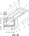
- the counter with air conditioning and freezing system of the present invention is seen for example in Figures 1A-B and Figures 2A-B .
- the counter comprises a self-supporting structure (C) with an insulated housing in which at least one support for trays (A, B) is located and with an air conditioning and freezing element which allows the temperature of an air current circulating through the self-supporting structure (C) to be modified.
- the counter comprises two supports for trays (A, B) arranged at different heights so that the user has better visual access to the products which are placed on the corresponding trays.
- FIGS 1A-B two sectioned views of the counter in an open position are represented. As can be seen, in this case, a first tray support (A) protrudes outside of the housing of the self-supporting structure (C) and a second tray support (B) is arranged flush with an upper opening of said housing.
- Figures 3A shows an air curtain created in the counter over the supports for trays (A, B) in an open position of the counter. This air curtain guarantees that the products located on the trays are maintained in correct temperature conditions.
- Figure 3B shows the counter in a closed position. The direction of the air recirculating through the interior of the self-supporting structure (C), around the housing, has been indicated. This recirculation of the air allows the products to be air conditioned and/or frozen to the desired temperature when the counter is closed.
- the counter has a geometry such that it allows the formation of a second air curtain in the rear part of the counter in the manner of rear protection.
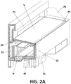
- the counter comprises an insulated interior air conditioning and freezing system (R) arranged on the self-supporting structure (C) configured to direct an air current through the interior of the self-supporting structure (C).
- This system (R) comprises a frontal return opening (R1) arranged in an upper frontal section of the support structure (C). Additionally, it comprises an insulated frontal vertical return (R2) by way of which the air current pass, entering through the frontal return opening (R1), passes. It also has a horizontal air passage (R4) connected to the insulated frontal vertical return (R2) by way of a first grill (R3) and which is arranged below the housing. It also has an insulated rear vertical return (R7) through which the air, arriving from the horizontal air passage (R4) by way of a second grill (R6), passes and which is connected by way of a third grill (R9) to the housing.
- the insulated horizontal air passage (R4) is defined by a horizontal sheet (R5) which passes through an evaporator (N) which can be in any position of the structure always inside the thermally insulated self-supporting structure (C).
- the air is preferably displaced from the insulated horizontal passage (R4) to the rear vertical return (R7) by way of a second grill (R6) forced by means of fans (O).
- the horizontal sheet (R5) delimits the housing, that is to say, the volume where the supports for trays (A, B) perform their movement and the frontal and rear vertical air returns (R2, R7) and the horizontal air passage (R4).
- the counter comprises an insulated exterior air conditioning and freezing system (D).
- This system (D) extends from a rear section of the self-supporting structure (C). As can be seen in the figures, it comprises at least one thermally insulated column (D1) which extends from the self-supporting structure (C) and which is hollow and is connected to the insulated rear vertical return (R7) to allow the passage of the air from said insulated rear vertical return (R7). Additionally, it has a thermally insulated horizontal conduit (D2) connected to the at least one thermally insulated column (D1) for the passage of the air from said thermally insulated column (D1).
- Figure 4 shows an upper sectioned view of the counter in which an embodiment is observed which comprises two thermally insulated columns (D1). Additionally, in Figure 5 , a sectioned frontal view has been represented in which the interior of the self-supporting structure (C) is seen and where the housing with the tray supports can be seen which, in this case, are two tray supports (A, B). The insulated horizontal air passage (R4) and a third grill (R9) can also be seen.
- the third grill (R9) can be arranged at any height within the counter and, in the embodiments, in which it is present, it is located between the insulated rear vertical return (R7) and the housing and is capable of moving between a closed position in which it prevents the passage of the air from said insulated rear vertical return (R7) to the housing and an open position in which it allows said passage.
- the counter preferably comprises a plurality of internal deflectors configured to distribute the air through the interior of the insulated exterior air conditioning and freezing system (D) and the interior of the conduits of the insulated interior air conditioning and freezing conduits (R).
- Figure 6 shows a plurality of possible configuration options of the thermally insulated horizontal conduit (D2), the groove (D3) and the exterior plate (D4).
- the insulated exterior air conditioning and freezing system (D) also comprises one or more secondary plates (D5) arranged at least partially in the insulated horizontal conduit (D2) and in the insulated columns (D1) to control the direction of the air displaced towards said insulated horizontal conduit (D2) from the thermally insulated columns (D1). It also allows the direction in which the air is directed towards the groove (D3) to be controlled.
- the secondary plates (D5) may be extendable, be movable or be fixed.
- the counter has additional heating systems.
- the additional heating systems comprise variable electrical resistors or similar elements along the thermally insulated horizontal conduit (D2) to produce hot air.
- the resistors are preferably regulated from the exterior.
- the counter preferably also comprises at least one valve (R8) arranged at the end of the thermally insulated columns (D1) which connects to the insulated interior air conditioning and freezing system (R).
- the valve (R8) can move between a closed position in which it prevents the passage of conditioned or frozen air from the insulated interior air conditioning and freezing system (R) towards the insulated exterior air conditioning and freezing system (D) and an open position in which it allows said passage.
- the counter can be in a closed position, in which case the valve (R8) is closed and the third grill (R9) is open; it can be in first open position, in which case both the valve (R8) and the third grill (R9) are open; or in a second open position, in which case the valve (R8) is open and the third grill (R9) is closed.
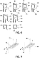
- FIG. 7 shows an exemplary embodiment of said valve (R8).
- the valve (R8) comprises a manual or automatic adjustor which is actuated from the exterior of the counter.
- the valve (R8) is made to pass from an open position to a closed position and vice versa by means of the adjustor.
- it is a plurality of sheets (I) which can turn around their longitudinal axis to pass from a position in which they are aligned, preventing the passage of the air towards the columns (D1) and positions in which they are parallel to one another, allowing the passage of air between them.
- FIGS 8A-B show another exemplary embodiment of the valve (R8).
- it is a solution comprising a body tilting around an axis joined to an interior wall of the column (D1) or the rear vertical return (R7) in the area in which it is joined to the columns (D1). It can have a handle (H) to facilitate its actuation (that is to say, its tilting).
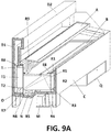
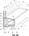
- Figures 9A-B show an exemplary embodiment in which the counter comprises a deflector (T) arranged in the insulated rear vertical return (R7).
- Said deflector (T) is, in this case, a flap rotating around a central vertical axis (T1).
- T1 central vertical axis
- the deflector (T) is smaller than the insulated rear vertical return (R7) such that it is created a bottom fixed air passage (T2).
- FIGS 10A-B show another exemplary embodiment in which the deflector (T) comprises a central fixed plate and two flaps (TS', TI') rotating around a horizontal central axis.
- One of said flaps (TS', TI') is situated on the central fixed plate and the other is situated below.
- the flaps can be in a position in which they prevent the passage of air through them or in a position in which they allow this and direct the air in the desired direction. Additionally, one of them can be closed and the other open.
- the deflector (T) comprises a plurality of sheets (T3) which can rotate around a horizontal central longitudinal axis.
- T3 the deflector
- the sheets are aligned with one another and the passage of air is prevented.
- the deflector (T) is in the open position, the sheets are parallel to one another, allowing the passage of the air through the spaces which are free between them.
- the direction of the air is controlled by means of the greater or lesser degree of inclination of the position of the sheets (T3).
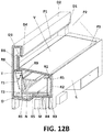
- Figures 12A-B show an exemplary embodiment in which the deflector (T) is a flap which can tilt around a horizontal axis (T1) arranged in the joining area with the air conditioning and freezing system (D) where the valve (R8) is located.
- the deflector (T) is smaller than the insulated rear vertical return (R7) such that it is created a bottom fixed air passage (T2).
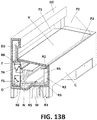
- Figures 13A-B show another embodiment in which the deflector (T) comprises two flaps which each tilt around a horizontal axis, opposing one another such that each of them tilts in the opposite direction to the other.
- the first tilting flap (T4) tilts around an axis arranged in the joining area to the air conditioning and freezing system (D) where the valve (R8) is located.
- the second flap (T5) tilts around an axis arranged in the lower area of the air redirection conduits (R2).
- the counter comprises at least lateral protectors (P2) and/or a rear protector (P1) which delimits the space in which the temperature is controlled. Additionally, it can also comprises a minimal frontal protector (P3), arranged in correspondence with the frontal return opening (R1) configured to ensure that the air exiting the longitudinal groove (R3) enters through said frontal return opening (R1) and/or a total frontal protector (P4) as is shown in Figure 14A (especially indicated when the products being displayed are frozen products). These protectors can be made of glass, methacrylate or similar materials.
- the lateral protections (P2) ensure the collection of the majority of the air coming from the insulated horizontal conduit (D2) and direct it towards the frontal return opening (R1).
- Figure 14B shows a sectioned view of the counter in which the lifting system of the tray supports (A, B) can be seen.
- This lifting system is configured to allow the displacement in the vertical direction of the tray supports (A, B) from the interior of the housing to a position in which the first tray (A) is outside of the housing and the second tray (B) is aligned with the opening of the housing.
- the lifting system comprises at least one joining means (E1) between a guide (E2) and the second tray support (B) which can move in the ascending/descending vertical direction. And these elements are connected to a motor (S). It preferably also comprises a perimeter sheet (E8) to prevent the falling of food into the interior of the counter.
- the lifting system can comprise security protections (E3) to prevent the risk of entrapment. They can be a type of fixed or movable guard with an interlock (or with an interlock and block).
- the lifting system is supported on a lower base of the self-supporting structure (E4) which is thermally insulated.
- the lifting system is also accessible from the exterior by means of a cover of the thermally insulated lifting system (E5).
- the lower base of the lifting system is defined by a lower plate (E6) in the manner of a lower stop which can contain a stop elastomer and which geometrically determines a volume in a base of the lifting system (E7) which is used to deposit grease and particles and which is accessible from the exterior.
- the lifting system is preferably housed in a compartment (E9) in the interior of the self-supporting structure (C) protected by the security protections (E3) to prevent the risk of entrapment and prevent splashes of grease and other splashes.
- the lifting system comprises at least two positions for the tray supports (A, B) which are controlled by means of limit switch sensors or similar. Said positions correspond to a display position and a storage position.
- the counter comprises wheels in the self-supporting structure (C) arranged in the lower section thereof configured to facilitate its displacement.
- C self-supporting structure
- M air conditioning and freezing element
- the water (dirty water with possible residues) is collected in a collector (Z) in the tray supports themselves (A, B) which are inclined towards said collector (Z) to prevent the water of the products displacing towards the bottom of the counter. It is collected there and is channelled to a reservoir situated on the exterior of the counter (Z1).
- the motor which controls the air conditioning and freezing element can be situated both in the interior of the counter and on the exterior.
- air conditioning and freezing system internal and exterior
- raising and lowering movement system of the supports of the trays are controlled from the exterior, manually and/or automatically.
- the counter can also comprise an auxiliary storage drawer (Q) which can also be air conditioned and/or frozen. Additionally, the counter can comprise a removable lower thermally insulated cover (W) for the maintenance of the evaporator (N).
- Q auxiliary storage drawer
- W removable lower thermally insulated cover
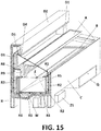
- FIG 15 a sectioned view of the counter is observed in which the air passage is observed only through the exterior air conditioning and freezing system, that is to say, with the counter in the second open position.
- Figure 16 shows an exemplary embodiment of the counter with rounded edges.
- An exterior plate can also be seen in the figure which directs the flow of air from the exterior air conditioning/freezing system towards the frontal vertical return of the interior of the counter.
Landscapes
- Physics & Mathematics (AREA)
- Thermal Sciences (AREA)
- Cold Air Circulating Systems And Constructional Details In Refrigerators (AREA)
- Air-Flow Control Members (AREA)
- Freezers Or Refrigerated Showcases (AREA)
- Devices That Are Associated With Refrigeration Equipment (AREA)
- Other Air-Conditioning Systems (AREA)
Priority Applications (8)
| Application Number | Priority Date | Filing Date | Title |
|---|---|---|---|
| ES18382537T ES2797476T3 (es) | 2018-07-18 | 2018-07-18 | Mostrador con sistema de climatización y congelación |
| EP18382537.1A EP3552525B1 (de) | 2018-07-18 | 2018-07-18 | Theke mit klimaanlage und gefriersystem |
| US17/055,794 US11185174B2 (en) | 2018-07-18 | 2019-04-12 | Counter with air conditioning and freezing system |
| CZ2020660A CZ308965B6 (cs) | 2018-07-18 | 2019-04-12 | Pult s klimatizačním a mrazicím systémem |
| MX2020013237A MX2020013237A (es) | 2018-07-18 | 2019-04-12 | Mostrador con sistema de acondicionamiento de aire y congelacion. |
| PCT/EP2019/059492 WO2020015870A1 (en) | 2018-07-18 | 2019-04-12 | Counter with air conditioning and freezing system |
| CN201980038075.XA CN112261892B (zh) | 2018-07-18 | 2019-04-12 | 具有空调和冷冻系统的柜台 |
| PT2019059492A PT2020015870B (pt) | 2018-07-18 | 2019-04-12 | Expositor com sistema de climatização e congelamento |
Applications Claiming Priority (1)
| Application Number | Priority Date | Filing Date | Title |
|---|---|---|---|
| EP18382537.1A EP3552525B1 (de) | 2018-07-18 | 2018-07-18 | Theke mit klimaanlage und gefriersystem |
Publications (2)
| Publication Number | Publication Date |
|---|---|
| EP3552525A1 true EP3552525A1 (de) | 2019-10-16 |
| EP3552525B1 EP3552525B1 (de) | 2020-04-15 |
Family
ID=63524233
Family Applications (1)
| Application Number | Title | Priority Date | Filing Date |
|---|---|---|---|
| EP18382537.1A Active EP3552525B1 (de) | 2018-07-18 | 2018-07-18 | Theke mit klimaanlage und gefriersystem |
Country Status (8)
| Country | Link |
|---|---|
| US (1) | US11185174B2 (de) |
| EP (1) | EP3552525B1 (de) |
| CN (1) | CN112261892B (de) |
| CZ (1) | CZ308965B6 (de) |
| ES (1) | ES2797476T3 (de) |
| MX (1) | MX2020013237A (de) |
| PT (1) | PT2020015870B (de) |
| WO (1) | WO2020015870A1 (de) |
Families Citing this family (1)
| Publication number | Priority date | Publication date | Assignee | Title |
|---|---|---|---|---|
| ES2797476T3 (es) * | 2018-07-18 | 2020-12-02 | Melius Integral S L | Mostrador con sistema de climatización y congelación |
Citations (3)
| Publication number | Priority date | Publication date | Assignee | Title |
|---|---|---|---|---|
| CH460066A (de) * | 1966-11-18 | 1968-07-31 | Bbc Brown Boveri & Cie | Kühlregal mit mehreren übereinanderliegenden Etageren mit Luftumwälzung im Kühlkreislauf |
| NL8502329A (nl) * | 1985-08-23 | 1987-03-16 | Frimex B V | Gekoelde toonbank, kast of dergelijke. |
| EP2374377A1 (de) * | 2010-04-06 | 2011-10-12 | Soremartec S.A. | Schaukasten |
Family Cites Families (14)
| Publication number | Priority date | Publication date | Assignee | Title |
|---|---|---|---|---|
| US4341082A (en) * | 1979-02-14 | 1982-07-27 | Tyler Refrigeration Corporation | Open top refrigerated display case having ambient air defrost |
| US5675983A (en) * | 1996-09-11 | 1997-10-14 | Kysor Industrial Corporation | Synergistic refrigerated display case |
| JPH11183013A (ja) * | 1997-12-19 | 1999-07-06 | Fuji Electric Co Ltd | 冷気循環式オープンショーケース |
| BRPI0401193A (pt) * | 2004-04-01 | 2005-11-22 | Multibras Eletrodomesticos Sa | Aparelho de refrigeração |
| WO2006039043A1 (en) * | 2004-09-30 | 2006-04-13 | Carrier Corporation | Curtain air admission assembly |
| JP2006242449A (ja) * | 2005-03-02 | 2006-09-14 | Sanden Corp | ショーケース |
| WO2006101517A1 (en) * | 2005-03-18 | 2006-09-28 | Carrier Corporation | Refrigerated merchandiser |
| KR20110021937A (ko) * | 2008-05-23 | 2011-03-04 | 악티에볼라겟 엘렉트로룩스 | 냉각 기기 |
| CN201637002U (zh) * | 2010-04-29 | 2010-11-17 | 成都军通通信股份有限公司 | 3g基站td室外单元设备制冷箱 |
| DE102012107713B4 (de) * | 2012-08-22 | 2018-02-15 | Aht Cooling Systems Gmbh | Kühlregal |
| IT201600070459U1 (it) * | 2016-07-06 | 2018-01-06 | Arneg | Gruppo espositore refrigerato combinato. |
| CN207168278U (zh) * | 2016-11-11 | 2018-04-03 | 河南统一电器股份有限公司 | 一种带双循环风系统的风幕柜 |
| CN107246754B (zh) * | 2017-06-22 | 2019-09-20 | 海信容声(广东)冷柜有限公司 | 一种风冷卧式冷柜 |
| ES2797476T3 (es) * | 2018-07-18 | 2020-12-02 | Melius Integral S L | Mostrador con sistema de climatización y congelación |
-
2018
- 2018-07-18 ES ES18382537T patent/ES2797476T3/es active Active
- 2018-07-18 EP EP18382537.1A patent/EP3552525B1/de active Active
-
2019
- 2019-04-12 WO PCT/EP2019/059492 patent/WO2020015870A1/en not_active Ceased
- 2019-04-12 CN CN201980038075.XA patent/CN112261892B/zh active Active
- 2019-04-12 CZ CZ2020660A patent/CZ308965B6/cs unknown
- 2019-04-12 US US17/055,794 patent/US11185174B2/en active Active
- 2019-04-12 MX MX2020013237A patent/MX2020013237A/es unknown
- 2019-04-12 PT PT2019059492A patent/PT2020015870B/pt active IP Right Grant
Patent Citations (3)
| Publication number | Priority date | Publication date | Assignee | Title |
|---|---|---|---|---|
| CH460066A (de) * | 1966-11-18 | 1968-07-31 | Bbc Brown Boveri & Cie | Kühlregal mit mehreren übereinanderliegenden Etageren mit Luftumwälzung im Kühlkreislauf |
| NL8502329A (nl) * | 1985-08-23 | 1987-03-16 | Frimex B V | Gekoelde toonbank, kast of dergelijke. |
| EP2374377A1 (de) * | 2010-04-06 | 2011-10-12 | Soremartec S.A. | Schaukasten |
Also Published As
| Publication number | Publication date |
|---|---|
| US11185174B2 (en) | 2021-11-30 |
| ES2797476T3 (es) | 2020-12-02 |
| US20210227997A1 (en) | 2021-07-29 |
| WO2020015870A1 (en) | 2020-01-23 |
| CZ308965B6 (cs) | 2021-10-20 |
| CN112261892A (zh) | 2021-01-22 |
| CN112261892B (zh) | 2023-05-09 |
| CZ2020660A3 (cs) | 2021-01-27 |
| PT2020015870B (pt) | 2021-03-03 |
| MX2020013237A (es) | 2021-05-12 |
| EP3552525B1 (de) | 2020-04-15 |
Similar Documents
| Publication | Publication Date | Title |
|---|---|---|
| US7220946B2 (en) | Food container | |
| US4920764A (en) | Refrigeration unit for vending machines | |
| US20110005409A1 (en) | Heated air curtain container with multiple temperature zones | |
| US5168719A (en) | Food preparation table with open air food storage | |
| US5475987A (en) | Refrigerated display case apparatus with enhanced airflow and improved insulation construction | |
| KR102679302B1 (ko) | 냉장고 | |
| US20090090734A1 (en) | Apparatus and method for single or multiple temperature zone(s) in refrigerated vending machine | |
| US6817201B2 (en) | Hot/cold product merchandiser | |
| US9175900B2 (en) | Refrigerator having sliding and pivoting doors | |
| WO2015183156A1 (en) | A covering arrangement for a refrigerated food bar arrangement and a food bar arrangement with such a covering arrangement | |
| US2826046A (en) | Refrigerated display case | |
| EP3552525B1 (de) | Theke mit klimaanlage und gefriersystem | |
| EP3803239B1 (de) | Kühlgerät mit ausziehbarem wagen | |
| EP3415846B1 (de) | Sektorisierte kühlanordnung für kühlschränke | |
| AU3154399A (en) | Refrigerating drawer for storage column | |
| JP2010042233A (ja) | 冷蔵キャビネット用クロージングシステム | |
| HK40013829A (en) | Counter with air conditioning and freezing system | |
| JP2008202937A (ja) | ショーケース | |
| US9829240B2 (en) | Domestic refrigeration appliance with an inner container and a base | |
| EP3531877B1 (de) | Verkaufskühlvitrine | |
| US2257247A (en) | Vegetable display case | |
| US2259993A (en) | Refrigerator cabinet | |
| EP4015950B1 (de) | Kühltheke für kühlgut | |
| JP2006308194A (ja) | 冷蔵ショーケース | |
| DE202017006847U1 (de) | Warenpräsenter zur Präsentation warmer und/oder kalter Speisen oder Getränke |
Legal Events
| Date | Code | Title | Description |
|---|---|---|---|
| PUAI | Public reference made under article 153(3) epc to a published international application that has entered the european phase |
Free format text: ORIGINAL CODE: 0009012 |
|
| STAA | Information on the status of an ep patent application or granted ep patent |
Free format text: STATUS: THE APPLICATION HAS BEEN PUBLISHED |
|
| AK | Designated contracting states |
Kind code of ref document: A1 Designated state(s): AL AT BE BG CH CY CZ DE DK EE ES FI FR GB GR HR HU IE IS IT LI LT LU LV MC MK MT NL NO PL PT RO RS SE SI SK SM TR |
|
| AX | Request for extension of the european patent |
Extension state: BA ME |
|
| STAA | Information on the status of an ep patent application or granted ep patent |
Free format text: STATUS: REQUEST FOR EXAMINATION WAS MADE |
|
| GRAP | Despatch of communication of intention to grant a patent |
Free format text: ORIGINAL CODE: EPIDOSNIGR1 |
|
| STAA | Information on the status of an ep patent application or granted ep patent |
Free format text: STATUS: GRANT OF PATENT IS INTENDED |
|
| 17P | Request for examination filed |
Effective date: 20200120 |
|
| RAV | Requested validation state of the european patent: fee paid |
Extension state: MA Effective date: 20200120 Extension state: TN Effective date: 20200120 |
|
| RBV | Designated contracting states (corrected) |
Designated state(s): AL AT BE BG CH CY CZ DE DK EE ES FI FR GB GR HR HU IE IS IT LI LT LU LV MC MK MT NL NO PL PT RO RS SE SI SK SM TR |
|
| GRAS | Grant fee paid |
Free format text: ORIGINAL CODE: EPIDOSNIGR3 |
|
| GRAA | (expected) grant |
Free format text: ORIGINAL CODE: 0009210 |
|
| STAA | Information on the status of an ep patent application or granted ep patent |
Free format text: STATUS: THE PATENT HAS BEEN GRANTED |
|
| INTG | Intention to grant announced |
Effective date: 20200220 |
|
| RIN1 | Information on inventor provided before grant (corrected) |
Inventor name: PONCE, LUIS Inventor name: PRIO SULLA, JAVIER Inventor name: PONCE, RAMON |
|
| AK | Designated contracting states |
Kind code of ref document: B1 Designated state(s): AL AT BE BG CH CY CZ DE DK EE ES FI FR GB GR HR HU IE IS IT LI LT LU LV MC MK MT NL NO PL PT RO RS SE SI SK SM TR |
|
| REG | Reference to a national code |
Ref country code: CH Ref legal event code: EP |
|
| REG | Reference to a national code |
Ref country code: DE Ref legal event code: R096 Ref document number: 602018003821 Country of ref document: DE |
|
| REG | Reference to a national code |
Ref country code: IE Ref legal event code: FG4D |
|
| REG | Reference to a national code |
Ref country code: AT Ref legal event code: REF Ref document number: 1256294 Country of ref document: AT Kind code of ref document: T Effective date: 20200515 |
|
| REG | Reference to a national code |
Ref country code: CH Ref legal event code: NV Representative=s name: VALIPAT S.A. C/O BOVARD SA NEUCHATEL, CH Ref country code: MA Ref legal event code: VAGR Ref document number: 49077 Country of ref document: MA Kind code of ref document: B1 |
|
| REG | Reference to a national code |
Ref country code: NL Ref legal event code: FP |
|
| REG | Reference to a national code |
Ref country code: HK Ref legal event code: DE Ref document number: 40013829 Country of ref document: HK |
|
| REG | Reference to a national code |
Ref country code: LT Ref legal event code: MG4D |
|
| PG25 | Lapsed in a contracting state [announced via postgrant information from national office to epo] |
Ref country code: LT Free format text: LAPSE BECAUSE OF FAILURE TO SUBMIT A TRANSLATION OF THE DESCRIPTION OR TO PAY THE FEE WITHIN THE PRESCRIBED TIME-LIMIT Effective date: 20200415 Ref country code: PT Free format text: LAPSE BECAUSE OF FAILURE TO SUBMIT A TRANSLATION OF THE DESCRIPTION OR TO PAY THE FEE WITHIN THE PRESCRIBED TIME-LIMIT Effective date: 20200817 Ref country code: NO Free format text: LAPSE BECAUSE OF FAILURE TO SUBMIT A TRANSLATION OF THE DESCRIPTION OR TO PAY THE FEE WITHIN THE PRESCRIBED TIME-LIMIT Effective date: 20200715 Ref country code: SE Free format text: LAPSE BECAUSE OF FAILURE TO SUBMIT A TRANSLATION OF THE DESCRIPTION OR TO PAY THE FEE WITHIN THE PRESCRIBED TIME-LIMIT Effective date: 20200415 Ref country code: IS Free format text: LAPSE BECAUSE OF FAILURE TO SUBMIT A TRANSLATION OF THE DESCRIPTION OR TO PAY THE FEE WITHIN THE PRESCRIBED TIME-LIMIT Effective date: 20200815 Ref country code: FI Free format text: LAPSE BECAUSE OF FAILURE TO SUBMIT A TRANSLATION OF THE DESCRIPTION OR TO PAY THE FEE WITHIN THE PRESCRIBED TIME-LIMIT Effective date: 20200415 |
|
| REG | Reference to a national code |
Ref country code: AT Ref legal event code: MK05 Ref document number: 1256294 Country of ref document: AT Kind code of ref document: T Effective date: 20200415 |
|
| PG25 | Lapsed in a contracting state [announced via postgrant information from national office to epo] |
Ref country code: RS Free format text: LAPSE BECAUSE OF FAILURE TO SUBMIT A TRANSLATION OF THE DESCRIPTION OR TO PAY THE FEE WITHIN THE PRESCRIBED TIME-LIMIT Effective date: 20200415 Ref country code: HR Free format text: LAPSE BECAUSE OF FAILURE TO SUBMIT A TRANSLATION OF THE DESCRIPTION OR TO PAY THE FEE WITHIN THE PRESCRIBED TIME-LIMIT Effective date: 20200415 Ref country code: LV Free format text: LAPSE BECAUSE OF FAILURE TO SUBMIT A TRANSLATION OF THE DESCRIPTION OR TO PAY THE FEE WITHIN THE PRESCRIBED TIME-LIMIT Effective date: 20200415 Ref country code: BG Free format text: LAPSE BECAUSE OF FAILURE TO SUBMIT A TRANSLATION OF THE DESCRIPTION OR TO PAY THE FEE WITHIN THE PRESCRIBED TIME-LIMIT Effective date: 20200715 |
|
| REG | Reference to a national code |
Ref country code: ES Ref legal event code: FG2A Ref document number: 2797476 Country of ref document: ES Kind code of ref document: T3 Effective date: 20201202 |
|
| PG25 | Lapsed in a contracting state [announced via postgrant information from national office to epo] |
Ref country code: AL Free format text: LAPSE BECAUSE OF FAILURE TO SUBMIT A TRANSLATION OF THE DESCRIPTION OR TO PAY THE FEE WITHIN THE PRESCRIBED TIME-LIMIT Effective date: 20200415 |
|
| REG | Reference to a national code |
Ref country code: DE Ref legal event code: R097 Ref document number: 602018003821 Country of ref document: DE |
|
| PG25 | Lapsed in a contracting state [announced via postgrant information from national office to epo] |
Ref country code: SM Free format text: LAPSE BECAUSE OF FAILURE TO SUBMIT A TRANSLATION OF THE DESCRIPTION OR TO PAY THE FEE WITHIN THE PRESCRIBED TIME-LIMIT Effective date: 20200415 Ref country code: EE Free format text: LAPSE BECAUSE OF FAILURE TO SUBMIT A TRANSLATION OF THE DESCRIPTION OR TO PAY THE FEE WITHIN THE PRESCRIBED TIME-LIMIT Effective date: 20200415 Ref country code: CZ Free format text: LAPSE BECAUSE OF FAILURE TO SUBMIT A TRANSLATION OF THE DESCRIPTION OR TO PAY THE FEE WITHIN THE PRESCRIBED TIME-LIMIT Effective date: 20200415 Ref country code: RO Free format text: LAPSE BECAUSE OF FAILURE TO SUBMIT A TRANSLATION OF THE DESCRIPTION OR TO PAY THE FEE WITHIN THE PRESCRIBED TIME-LIMIT Effective date: 20200415 Ref country code: DK Free format text: LAPSE BECAUSE OF FAILURE TO SUBMIT A TRANSLATION OF THE DESCRIPTION OR TO PAY THE FEE WITHIN THE PRESCRIBED TIME-LIMIT Effective date: 20200415 Ref country code: AT Free format text: LAPSE BECAUSE OF FAILURE TO SUBMIT A TRANSLATION OF THE DESCRIPTION OR TO PAY THE FEE WITHIN THE PRESCRIBED TIME-LIMIT Effective date: 20200415 |
|
| PLBE | No opposition filed within time limit |
Free format text: ORIGINAL CODE: 0009261 |
|
| STAA | Information on the status of an ep patent application or granted ep patent |
Free format text: STATUS: NO OPPOSITION FILED WITHIN TIME LIMIT |
|
| PG25 | Lapsed in a contracting state [announced via postgrant information from national office to epo] |
Ref country code: SK Free format text: LAPSE BECAUSE OF FAILURE TO SUBMIT A TRANSLATION OF THE DESCRIPTION OR TO PAY THE FEE WITHIN THE PRESCRIBED TIME-LIMIT Effective date: 20200415 Ref country code: MC Free format text: LAPSE BECAUSE OF FAILURE TO SUBMIT A TRANSLATION OF THE DESCRIPTION OR TO PAY THE FEE WITHIN THE PRESCRIBED TIME-LIMIT Effective date: 20200415 Ref country code: PL Free format text: LAPSE BECAUSE OF FAILURE TO SUBMIT A TRANSLATION OF THE DESCRIPTION OR TO PAY THE FEE WITHIN THE PRESCRIBED TIME-LIMIT Effective date: 20200415 |
|
| 26N | No opposition filed |
Effective date: 20210118 |
|
| PG25 | Lapsed in a contracting state [announced via postgrant information from national office to epo] |
Ref country code: LU Free format text: LAPSE BECAUSE OF NON-PAYMENT OF DUE FEES Effective date: 20200718 |
|
| PG25 | Lapsed in a contracting state [announced via postgrant information from national office to epo] |
Ref country code: IE Free format text: LAPSE BECAUSE OF NON-PAYMENT OF DUE FEES Effective date: 20200718 |
|
| PG25 | Lapsed in a contracting state [announced via postgrant information from national office to epo] |
Ref country code: TR Free format text: LAPSE BECAUSE OF FAILURE TO SUBMIT A TRANSLATION OF THE DESCRIPTION OR TO PAY THE FEE WITHIN THE PRESCRIBED TIME-LIMIT Effective date: 20200415 Ref country code: MT Free format text: LAPSE BECAUSE OF FAILURE TO SUBMIT A TRANSLATION OF THE DESCRIPTION OR TO PAY THE FEE WITHIN THE PRESCRIBED TIME-LIMIT Effective date: 20200415 Ref country code: CY Free format text: LAPSE BECAUSE OF FAILURE TO SUBMIT A TRANSLATION OF THE DESCRIPTION OR TO PAY THE FEE WITHIN THE PRESCRIBED TIME-LIMIT Effective date: 20200415 |
|
| PG25 | Lapsed in a contracting state [announced via postgrant information from national office to epo] |
Ref country code: MK Free format text: LAPSE BECAUSE OF FAILURE TO SUBMIT A TRANSLATION OF THE DESCRIPTION OR TO PAY THE FEE WITHIN THE PRESCRIBED TIME-LIMIT Effective date: 20200415 |
|
| PG25 | Lapsed in a contracting state [announced via postgrant information from national office to epo] |
Ref country code: GR Free format text: LAPSE BECAUSE OF FAILURE TO SUBMIT A TRANSLATION OF THE DESCRIPTION OR TO PAY THE FEE WITHIN THE PRESCRIBED TIME-LIMIT Effective date: 20200415 |
|
| P01 | Opt-out of the competence of the unified patent court (upc) registered |
Effective date: 20230511 |
|
| PG25 | Lapsed in a contracting state [announced via postgrant information from national office to epo] |
Ref country code: SI Free format text: LAPSE BECAUSE OF FAILURE TO SUBMIT A TRANSLATION OF THE DESCRIPTION OR TO PAY THE FEE WITHIN THE PRESCRIBED TIME-LIMIT Effective date: 20200415 |
|
| PGFP | Annual fee paid to national office [announced via postgrant information from national office to epo] |
Ref country code: NL Payment date: 20250724 Year of fee payment: 8 |
|
| PGFP | Annual fee paid to national office [announced via postgrant information from national office to epo] |
Ref country code: ES Payment date: 20250821 Year of fee payment: 8 |
|
| PGFP | Annual fee paid to national office [announced via postgrant information from national office to epo] |
Ref country code: DE Payment date: 20250728 Year of fee payment: 8 |
|
| PGFP | Annual fee paid to national office [announced via postgrant information from national office to epo] |
Ref country code: IT Payment date: 20250721 Year of fee payment: 8 |
|
| PGFP | Annual fee paid to national office [announced via postgrant information from national office to epo] |
Ref country code: BE Payment date: 20250724 Year of fee payment: 8 Ref country code: GB Payment date: 20250722 Year of fee payment: 8 |
|
| PGFP | Annual fee paid to national office [announced via postgrant information from national office to epo] |
Ref country code: FR Payment date: 20250725 Year of fee payment: 8 |
|
| PGFP | Annual fee paid to national office [announced via postgrant information from national office to epo] |
Ref country code: CH Payment date: 20250801 Year of fee payment: 8 |
|
| VSFP | Annual fee paid to validation state [announced via postgrant information from national office to epo] |
Ref country code: MA Payment date: 20230704 Year of fee payment: 6 |
|
| VSFP | Annual fee paid to validation state [announced via postgrant information from national office to epo] |
Ref country code: MA Payment date: 20220706 Year of fee payment: 5 Ref country code: MA Payment date: 20210630 Year of fee payment: 4 Ref country code: MA Payment date: 20200709 Year of fee payment: 3 |
|
| VSFP | Annual fee paid to validation state [announced via postgrant information from national office to epo] |
Ref country code: MA Payment date: 20240701 Year of fee payment: 7 |
|
| VSFP | Annual fee paid to validation state [announced via postgrant information from national office to epo] |
Ref country code: MA Payment date: 20250725 Year of fee payment: 8 |