EP3552478A2 - Machine-outil portative - Google Patents
Machine-outil portative Download PDFInfo
- Publication number
- EP3552478A2 EP3552478A2 EP19152041.0A EP19152041A EP3552478A2 EP 3552478 A2 EP3552478 A2 EP 3552478A2 EP 19152041 A EP19152041 A EP 19152041A EP 3552478 A2 EP3552478 A2 EP 3552478A2
- Authority
- EP
- European Patent Office
- Prior art keywords
- cutting
- unit
- force
- cutting device
- elements
- Prior art date
- Legal status (The legal status is an assumption and is not a legal conclusion. Google has not performed a legal analysis and makes no representation as to the accuracy of the status listed.)
- Granted
Links
Images


Classifications
-
- A—HUMAN NECESSITIES
- A01—AGRICULTURE; FORESTRY; ANIMAL HUSBANDRY; HUNTING; TRAPPING; FISHING
- A01G—HORTICULTURE; CULTIVATION OF VEGETABLES, FLOWERS, RICE, FRUIT, VINES, HOPS OR SEAWEED; FORESTRY; WATERING
- A01G3/00—Cutting implements specially adapted for horticultural purposes; Delimbing standing trees
- A01G3/02—Secateurs; Flower or fruit shears
- A01G3/033—Secateurs; Flower or fruit shears having motor-driven blades
- A01G3/037—Secateurs; Flower or fruit shears having motor-driven blades the driving means being an electric motor
-
- B—PERFORMING OPERATIONS; TRANSPORTING
- B26—HAND CUTTING TOOLS; CUTTING; SEVERING
- B26B—HAND-HELD CUTTING TOOLS NOT OTHERWISE PROVIDED FOR
- B26B15/00—Hand-held shears with motor-driven blades
-
- H—ELECTRICITY
- H02—GENERATION; CONVERSION OR DISTRIBUTION OF ELECTRIC POWER
- H02H—EMERGENCY PROTECTIVE CIRCUIT ARRANGEMENTS
- H02H5/00—Emergency protective circuit arrangements for automatic disconnection directly responsive to an undesired change from normal non-electric working conditions with or without subsequent reconnection
- H02H5/04—Emergency protective circuit arrangements for automatic disconnection directly responsive to an undesired change from normal non-electric working conditions with or without subsequent reconnection responsive to abnormal temperature
-
- H—ELECTRICITY
- H02—GENERATION; CONVERSION OR DISTRIBUTION OF ELECTRIC POWER
- H02H—EMERGENCY PROTECTIVE CIRCUIT ARRANGEMENTS
- H02H9/00—Emergency protective circuit arrangements for limiting excess current or voltage without disconnection
- H02H9/02—Emergency protective circuit arrangements for limiting excess current or voltage without disconnection responsive to excess current
-
- H—ELECTRICITY
- H02—GENERATION; CONVERSION OR DISTRIBUTION OF ELECTRIC POWER
- H02J—ELECTRIC POWER NETWORKS; CIRCUIT ARRANGEMENTS OR SYSTEMS FOR SUPPLYING OR DISTRIBUTING ELECTRIC POWER; SYSTEMS FOR STORING ELECTRIC ENERGY
- H02J7/00—Circuit arrangements for charging or discharging batteries or for supplying loads from batteries
- H02J7/865—Battery or charger load switching, e.g. concurrent charging and load supply
-
- H—ELECTRICITY
- H02—GENERATION; CONVERSION OR DISTRIBUTION OF ELECTRIC POWER
- H02J—ELECTRIC POWER NETWORKS; CIRCUIT ARRANGEMENTS OR SYSTEMS FOR SUPPLYING OR DISTRIBUTING ELECTRIC POWER; SYSTEMS FOR STORING ELECTRIC ENERGY
- H02J2105/00—Networks for supplying or distributing electric power characterised by their spatial reach or by the load
- H02J2105/40—Networks for supplying or distributing electric power characterised by their spatial reach or by the load characterised by the loads connecting to the networks or being supplied by the networks
Definitions
- the invention relates to a hand tool, in particular a cutting device, comprising a DC motor, a particular rechargeable battery that powers the engine, a voltage monitoring device that monitors the voltage of the battery and a control device that controls the power supply of the battery to the motor monitors or regulates.
- the maximum current output of the battery to the motor is limited as a function of a battery voltage dropping by discharge, in particular in order to avoid a motor stall.
- DC motors have different maximum current values above which the motor stops (stall). In the "stall” it comes to brush fire, causing the brushes erode quickly and / or a rapid battery discharge and / or overheating of the engine and / or other negative influences, which damages the hand tool or its components.
- the handheld power tool has a temperature monitoring device.
- the temperature monitoring device can limit the maximum current output as a function of the temperature. In this case, the maximum current output is more limited than at lower temperature, especially at higher temperatures. As a result, a "stall" can be reliably avoided even at different temperatures or the hand tool machine can be operated at all operating temperatures in the respective maximum current delivery range.
- the power tool has a plurality of modes, the maximum power output depending on the choice of mode (for example, light, medium, heavy) is limited.
- the maximum power output depending on the choice of mode for example, light, medium, heavy
- a user can adjust the machine depending on the application.
- pruning shears for example, when cutting ornamental trees, the manual force support can be set weaker than when cutting commercial trees or even shredding vegetation waste.
- the power tool has a plurality of discrete voltage values, for example 3.3 V, 3.5 V, 3.7 V, 3.9 V and / or 4.2 V, as a function of which the maximum current output is limited for example to 11A, 14A, 16A and / or 18A.
- the handheld power tool is a cutting device with a first and a second relatively movable cutting element and with a first and a second relatively movable handle element, with an arranged between the handle elements opening spring, with at least one drive unit in the form of Motor, which is provided in at least one operating state, at least to support a movement of the second cutting element relative to the first cutting element and at least one driving force transmission element, which is at least in the one operating state with the drive unit in operative connection. Since the force requirement is very high in cutting devices, especially pruning shears and the closing speed of the scissor halves relatively high, often high currents for closing the scissor halves are needed, especially in support mode, which can lead to "stable". By the aforementioned invention, it is possible to effectively avoid this and thereby increase the user-friendliness of the cutting device.
- the invention is based on a handheld power tool, in particular a cutting device, comprising a DC motor, in particular a rechargeable battery or accumulator, which supplies the motor with energy, further comprising a voltage monitoring device which monitors the voltage of the battery and a control - or regulating device which monitors or regulates the power supply from the battery to the engine.
- a handheld power tool in particular a cutting device, comprising a DC motor, in particular a rechargeable battery or accumulator, which supplies the motor with energy, further comprising a voltage monitoring device which monitors the voltage of the battery and a control - or regulating device which monitors or regulates the power supply from the battery to the engine.
- control device drive the motor in particular for at least a short time, in particular a few milliseconds, when the battery is being charged or when the handheld power tool is being connected to a charging device. This will give the user feedback that the loading process has started or ended. An additional loading indication can potentially be omitted.
- a functional test of the power tool is carried out (wiring, battery, engine, control or regulation are intact). The user is immediately in the picture or informed that the hand tool is in principle functional. Due to the limitation of the drive time there is also no risk of injury, particularly preferably in a relatively slow-moving cutting device, such as pruning shears.
- an aforementioned hand tool in particular a cutting device, in particular a pruning shears claimed that allows manual and a manual-machine-supported operation.
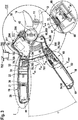
- FIG. 1 shows a cutting device 10 according to the invention.
- the cutting device 10 is designed as a garden cutting device.
- the cutting device 10 is designed as a secateurs.
- the cutting device is designed as a battery-operated cutting device 10.
- another embodiment of the cutting device 10 would be conceivable, for example as a carpet or sheet metal shears or the like.
- the cutting device 10 has two cutting elements 12, 14 movable relative to each other (FIG. FIG. 2 . 3 ).
- the cutting elements 12, 14 are pivotable relative to each other.
- a first cutting element 12 is formed as a passive cutting edge with a cutting edge.
- the second cutting element 14 is formed as an active cutting edge with a blade.
- the cutting device 10 has two gripping elements 16, 18 that are movable relative to one another.
- the gripping elements 16, 18 are pivotable relative to each other or rotatable.
- the grip elements 16, 18 are formed pivotable relative to each other via at least one pivot 42.
- the cutting elements 12, 14 are also formed via the rotary joint 42 pivotally to each other.
- the swivel joint 42 is arranged between the grip elements 16, 18 and the cutting elements 12, 14.
- the first handle member 16 and the first cutting member 12 are connected to each other and arranged on different sides of the pivot 42. Furthermore, the second gripping element 18 and the second cutting element 14 are at least indirectly connected to one another and arranged on different sides of the rotary joint 42.
- a power transmission element 800 here in the form of a lever 80, connects the second cutting element 14 to the second grip element 18.
- the grip elements 16, 18 are intended to be gripped by an operator.
- the grip members 16, 18 are intended to be received from an operator with the same Hand to be grabbed. In principle, however, it would also be conceivable that the cutting device 10 is intended for a two-handed operation. In this case, for example, further lever and / or translation elements could be provided to at least partially change a cutting force F cut relative to the force applied to the grip elements 16, 18, in particular an operating force F user .
- an opening spring 50 is arranged between the grip elements 16, 18.
- the opening spring 50 is arranged closer to the swivel joint 42 than at a free end of the grip elements 16, 18 with respect to a longitudinal extent of the grip elements 16, 18.
- the opening spring 50 is formed as a compression spring.
- the ends of the opening spring 50 are supported on the first and second handle members 16, 18.
- the opening spring 50 is provided to push the handle members 16, 18 apart and open the cutter 10 therewith.
- the opening spring 50 is further provided to receive and / or guide a drive force transmission element 340 operatively connected to a drive unit 20, here in the form of a cable 34, in a cavity formed by it, as will be explained below.
- a protective device 300 is further arranged.
- the protective device 300 extends between the two gripping elements 16, 18.
- the protective device 300 is advantageously fixedly connected to the second gripping element 18.
- the protection device 300 is also movably received in the first grip element 16.
- the protective device can be designed, for example, as a telescopic device or as a rigid device.
- the protective device 300 is provided to protect at least one cable (not shown) of the cutting device 10, which is guided by way of example from the first into the second grip elements 16, 18, from external influences and / or securely between the first and second grip elements 16, 18 record.
- the cable is for example a cable for the electrical connection of an energy storage unit 54 and a control unit 52 and / or a drive unit 20 or a sensor cable, which is guided from a 401 to the control unit 52.
- the protection device 300 also narrows one otherwise free space 301 between the pivot 42 and the opening spring 50 or at least partially fills it, so that for example a user accidentally can not easily put his finger in this space or a clippings, such as a branch or branch difficult in this Interstice can catch.
- the protective device 300 is also a locking device for the intermediate space 301.
- the intermediate space 301 between the rotary joint 42 and the opening spring 50 is particularly dangerous for a pinching of an object 17, in particular the fingers or the skin of an operator, since the acting in this area Forces due to the lever ratios or lever length of the handle members 16, 18 about the pivot 42 are high.
- the protection device 300 serves to avoid injury.
- the cutting device 10 has a drive unit 20.
- the drive unit 20 is designed as an electric motor.
- the electric motor is intended to be supplied with a voltage less than 110 V, in particular with a voltage of 1 V to 36 V, preferably 3.6 V.
- the drive unit 20 is arranged in the first grip element 16.
- the drive unit 20 is arranged in a grip housing 44 of the grip element 16.
- the drive unit 20 is arranged on a cutting elements 12, 14 facing away from the end of the first handle member 16.
- the handle housing 44 has two housing shells, in which the drive unit 20 is firmly received.
- the drive unit 20 is provided in at least one operating state to support a movement of the second cutting element 14 relative to the first cutting element 12.
- the drive unit 20 is intended to support a closing movement of the cutting device 10 carried out via the grip elements 16, 18 during heavy cutting operations. As a result, a force F user required for operating the cutting device 10 can be reduced by an operator.
- the cutting device 10 has a gear unit 38.
- the transmission unit 38 is arranged in the first grip element 16.
- the gear unit 38 is arranged in the grip housing 44 of the grip element 16.
- the gear unit 38 is arranged on a side facing the cutting elements 12, 14 side of the drive unit 20.
- the gear unit 38 is driven directly by the drive unit 20 in the present case.
- the transmission unit 38 is formed as a gear transmission unit.
- the gear unit 38 has at least one gear stage.
- the gear unit 38 advantageously has a plurality of gear stages.
- the gear unit 38 has in particular one to six gear stages, advantageously four gear stages.
- the at least one gear stage is designed as a planetary gear stage 381, 382, 383, 384.
- the transmission unit 38 is designed as a planetary gear unit ( FIG. 4 ).
- the ratio of the gear unit 38 advantageously has a ratio of 30: 1 to 300: 1, in particular of 100: 1 to 150: 1, in particular of 130: 1. In principle, however, another translation would be conceivable.
- the transmission unit 38 is mounted in the grip element 16 via a housing 74 of the transmission unit 38.
- the housing 74 of the gear unit 38 is formed by at least one ring gear 385 of the at least one planetary gear stage 381, 382, 383, 384.
- the housing 74 of the transmission unit 38 can also be formed from individual serially arranged ring gears of the planetary gear stages 381, 382, 383, 384.
- the power transmission within the at least one planetary gear stage 381, 382, 383, 384 takes place in each case by a driven sun gear 386 via planets 387 of the respective planetary gear stage, which are supported on a stationary ring gear 381, on a planet carrier 388 revolving around the planet 387.
- the planet carrier 388 in turn drives a sun gear of the next gear stage 382, 383, 384.
- the planet carrier 389 of the last gear stage 384 forms the output of the gear unit 38.
- the cutting device 10 further comprises a coupling unit 22 (FIG. FIG. 4 and 5 ) on.
- the coupling unit 22 is designed as a self-switching coupling unit 22.
- a "self-switching coupling unit” should be understood in this context, in particular a coupling unit 22, which is operated free of external, for example, electrical switching signals, in particular a control unit 52.
- Preferably should be underneath a coupling unit 22 are understood, which is actuated to a change between the coupling states free of explicit switching signals.
- this is to be understood as meaning a coupling unit 22 which is actuated on the basis of mechanical influencing factors.
- This is preferably understood to mean a coupling unit 22 which is actuated as a function of at least one parameter of a drive and / or output side.
- the coupling unit 22 can therefore be designed in particular speed-actuated, moment-actuated, direction-actuated and / or force-flow-actuated.
- the self-switching clutch unit 22 is designed as a one-way clutch.
- An "overrunning clutch” is to be understood in this context in particular a self-switching clutch, which is formed direction-actuated and / or force flow actuated.
- the overrunning clutch is at least directionally actuated.
- the one-way clutch is provided to open and / or close depending on a direction of rotation, in particular a drive and / or output side of the clutch unit 22, and / or depending on a direction of a force on the one-way clutch.
- the direction of the force can be distinguished, for example, whether the force acts on the overrunning clutch from the drive side or from the output side.
- the one-way clutch is provided to open or close the drive unit 20 in at least one operating state as a function of a direction of rotation, in particular a drive and / or output side, and / or depending on a direction of a force acting on the one-way clutch.
- the coupling unit 22 is arranged in the first grip element 16.
- the coupling unit 22 is arranged in the grip housing 44 of the first grip element 16.
- the clutch unit 22 is provided for decoupling the drive unit 20 in at least one operating state in which the drive unit 20 is deactivated.
- the drive unit 20 is automatically deactivated and the clutch unit 22 are automatically decoupled in the absence of rotational movement of the drive unit 20.
- a "decoupling of the drive unit” should in particular be understood to mean a decoupling of the drive unit 20 from a closing mechanism of the cutting device 10.
- the coupling unit 22 is in at least one operating state, in which the Drive unit 20 is deactivated, also provided for a decoupling of the transmission unit 38.
- the clutch unit 22 is provided at least for a realization of a complete manual operation to decouple the drive unit 20 and / or the transmission unit 38.
- a "complete manual operation” is to be understood in this context, in particular, an operating state in which the cutting device 10 is operated free of support of the drive unit 20.
- this is to be understood as an operating state in which the cutting device 10 is operated exclusively by the active force F user of an operator.
- Particularly preferred is to be understood as an operating state in which the drive unit 20 is decoupled and therefore can not be used to support a movement of the second cutting element 14 relative to the first cutting element 12.
- the cutting device 10 can be advantageously used without the drive unit 20, such as in a lack of power and / or light cutting work.
- the coupling unit 22 is advantageously provided for accelerating the opening or spreading movement of the two cutting elements 12, 14 or the two gripping elements 16, 18.
- the coupling unit 22 allows an accelerated up and / or unwinding of a drive force transmission element 340, here in the form of a rope 34, from a winch 32 or cable drum 320 of a winch 32, when opening or spreading the cutting device 10, as described below becomes.
- a drive force transmission element 340 here in the form of a rope 34
- the number of possible cuts per time unit can be increased.
- the coupling unit 22 is provided to decouple the drive unit 20 and to couple with a renewed closing movement with motor power assistance again ,
- the coupling unit 22 has an inner rotary member 46 and an outer rotary member 48.
- the inner rotary member 46 is in at least one state rotatable relative to the outer rotary member 48.
- the outer rotary element 48 is advantageously connected to the output of the gear unit 38.
- a part of the coupling unit 22 advantageously forms a part, in particular the last gear stage 384 of the gear unit 38.
- the outer rotary element 48 is advantageously integrally formed with the one part of the gear unit 38, in particular the planet carrier 389 of the last gear stage 384 and / or the output of the gear unit 38.
- the inner rotary member 46 and the outer rotary member 48 are secured to each other by means of a particular coaxial connecting element 47.
- the connecting element 47 is designed as a connecting pin.
- the connecting element 47 secures the inner and outer rotary elements 46, 48 at least axially and / or radially to each other.
- the connecting shaft 47 is preferably fixed, in particular frictionally connected with the outer rotary member 48 and at least rotationally play with the inner rotary member 46.
- the connecting shaft 47 is slidably received on the inner rotary member 46.
- the connecting shaft 47 also has a shoulder 471 for axially securing the inner rotary element 46 relative to the outer rotary element 48.
- the shoulder 471 is supported on a particular rim-like surface of the inner rotary member 46.
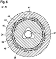
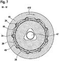
- the coupling unit 22 has a plurality of clamping bodies 24 (FIG. FIG. 6 and 7 ).
- a "clamping body” should be understood as meaning, in particular, an element of the coupling unit 22 which, in at least one operating state, in particular in a closed state of the coupling unit 22, is intended to jam between two rotationally rotatable elements of the coupling unit 22.
- the clamp bodies 24 are arranged between the inner rotary element 46 and the outer rotary element 48.
- the clamping body 24 are arranged in the circumferential direction one behind the other about the inner rotary member 46.
- the clamping body 24 are formed as a cylinder and / or roller, in particular as a cylindrical roller.
- the outer rotary element 48 has on its inside a plurality of circumferentially successive ramps 49.
- a number of ramps 49 corresponds to a number of clamping body 24.
- the clamping body 24 are movably arranged between the ramps 49, wherein upon rotation of the outer Rotary element 48 entrainment of the clamping body 24 takes place.
- the clamp bodies 24 roll in a narrow tapered region between the outer rotary member 48 and the inner rotary member 46 and are pressed against the inner rotary member 46. This is done with a drive of the outer rotary member 48 in the drive direction 41.
- a "drive direction” in particular a direction of rotation of the drive unit 20, in which the drive unit 20 in a regular operation, in particular to support a cutting movement rotates.
- the coupling unit 22 is closed in this state, as shown in the FIG. 6 is shown. If, however, the inner rotary member 46 is driven, regardless of a direction of rotation, the clamping body 24 remain in a valley of the ramps 49 or roll back into this and are spaced from the outer rotary member 48.
- the clamping body 24 are arranged freely between the rotary elements 46, 48. There is no rotary drive.
- the coupling unit 22 is opened in this state, as shown in the FIG. 7 is shown.
- the outer rotary element 46 is driven by the drive unit 20 via the gear unit 38.
- the gear unit 38 and the drive unit 20 form a drive side of the coupling unit 22. If the inner rotary member 46 is driven against a drive direction 41, the clamping body 24 are moved into the valley of the ramps 49 and are also freely between the rotary members 46, 48 are arranged.
- the self-switching coupling unit 22 is arranged spatially between the cutting elements 12, 14 and the drive unit 20.
- the self-switching coupling unit 22 is arranged spatially between a winch 32 and the transmission unit 38. At least the winch 32 or an output element of the Weilwinde 32 forms an output of the coupling unit 22nd
- the self-switching coupling unit 22 has a clamping body 24 receiving cage 26 ( FIG. 6 . 7 ).
- the cage 26 receives the clamping body 24 in separate receiving areas.
- the cage 26 serves to position and guide the clamping body 24 in the circumferential direction.
- the cage 26 is provided to space and uniformly distribute the clamp bodies 24 in the circumferential direction. In particular, it can be achieved in the case of a plurality of clamping bodies 24 that the clamping bodies 24 are in the circumferential direction perform the same movement. It may preferably be possible a controlled clamping of the clamping body 24.
- the cage 26 is partially annular.
- the cage 26 is partially cylindrical.
- a plurality of axially projecting, circular segment-shaped webs are applied, which extend in the circumferential direction between the clamping bodies 24.
- the cage 26 is mounted on the inner rotary member 46 of the coupling unit 22.
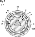
- the coupling unit 22 has a brake element 28 which is provided for braking the cage 26 ( FIG. 8 ).
- the brake element 28 is designed as a spring element.
- the brake element 28 is formed as a kind of spiral spring.
- the brake element 28 is designed as a wrap spring.
- the brake element 28 is arranged with one end fixed in a recess 29 of the cage 26.
- the brake element 28 extends at least partially in the circumferential direction helically around the cage 26.
- the brake element 28 wraps around the cage 26.
- An outer surface of the brake element 28 is supported at least partially on a braking element 28 and the cage 26 radially surrounding securing element 27 from.
- the securing element 27 is designed as a securing ring or fixing ring.
- the securing element 27 is fixedly arranged on the coupling unit 22.
- the securing element 27 is fixed, in particular at least rotationally fixed, preferably frictionally connected to the housing 23 of the coupling unit 22.
- the inner surface of the housing 23 is structured in the region of the area provided for the arrangement of the securing element 27, in particular corrugated.
- the brake member 28 allows rotation of the cage 26 relative to the fixed handle housing 44 in a rotational direction, in particular a drive rotational direction and locks a rotation of the cage 26 in the opposite direction of rotation.
- the brake member 28 allows rotation of the cage 26 relative to the housing 23 of the coupling unit 22 and the securing element 27 in one direction and blocks rotation of the cage 26 in the opposite direction of rotation.
- the brake element 28 is adapted to allow a freewheeling of the cage 26.
- the brake member 28 is adapted to the cage 26 in Counteract drive direction 410 to brake or inhibit rotation or to fix the cage and in the drive direction 41 to rotate the cage 26 relative to the outer support surface or the securing element 27 to allow, in particular to allow low friction.
- This type of loop coupling tows at a rotation of the cage 26 in the drive direction 41 with its free end and slides on the inner surface of the securing element 27.
- the braking element 28 is provided to prevent unwanted twisting of the cage 26.
- the brake element 28 is provided to prevent twisting of the cage 26 up to a force, in particular a force by the drive unit 20.
- the brake member 28 may also be formed as a pawl member, another freewheeling member or the like.
- the inner rotary element 46 has at least one, in particular two positive-locking element 460, 460 '.
- the form-fitting element is designed as a flange, but may also have a different shape.
- the cage 26 also has a positive-locking element 260.
- the rotary body 370 has a form-locking element 370.
- the securing element 27 has at least one interlocking element 270. At least via the interlocking elements 260, 270, 370, 460, 460 'as well as sometimes frictional connections between the rotary body 37 and the inner rotary element 46 elements of the coupling unit 22 and the return unit 31 are connected to each other secured. Thus, an axial securing of these elements is ensured to each other.
- the axial securing can also be done in other ways.
- An additional storage, for example by sliding or roller bearings can be advantageously eliminated.
- via the connecting element 47 and the outer rotary member 48 is axially secured to the inner rotary member 46 and thus positioned over the securing element 27 axially to the coupling unit 22.
- the cutting device 10 has a reset unit 31 ( FIG. 9 ).
- the reset unit 31 is arranged in the first grip element 16.
- the reset unit 31 is arranged on, advantageously in the handle housing 44 of the handle member 16.
- the reset unit 31 is in the coupling unit 22 arranged.
- the return unit 31 is provided to ensure a tension of the rope.
- the return unit 31 is provided to act on the winch 32 with a force, in particular with a force in the circumferential direction.
- the restoring unit 31 is provided to effect a tensile force on the cable 34 via the cable winch 32.
- the cable 34 is to be permanently held in tension via the return unit 31.
- the return unit 31 causes a restoring force F vs , which is lower than an opening force F os of the opening spring 50 (FIG. FIG. 3 ).
- a tension of the cable 34 can be ensured in particular even with a complete manual operation.
- an unwanted knotting the rope 34 can be advantageously prevented.
- a winding of the cable 34 can be ensured without drive.
- the reset unit 31 has a spring element 36 and a rotary body 37.
- One end of the spring element 36 is fixedly connected to the housing 23 of the coupling unit 22.
- the other end of the spring element 36 is fixedly connected to the rotary body 37.
- the spring element 36 is arranged radially between the housing 23 of the coupling unit 22 and the rotary body 37.
- the spring element 36 surrounds the rotary body 37 radially.
- the spring element 36 is wound several times around the rotary body 37.
- the reset unit 31 is at least indirectly connected to the cable winch 32, in particular via the rotary body 37.
- the rotary body 37 is limited rotatably fixed via the spring element 36 relative to the handle housing 44 and the housing 23 of the coupling unit 22.
- the rotary body 37 is connected via a shaft 35 with the winch 32.
- the rotary body 37 is advantageously also rotatably connected via the shaft 35 with the inner rotary member 46 of the clutch unit 22.
- the rotary body 37 may be connected to the inner rotary element 46 via at least one radial and / or axial positive locking element.
- the rotary body 37 has a coaxial recess.
- the recess is polygonal.
- the inner contour of the recess is formed corresponding to the outer contour of the shaft 35.
- the spring element 36 is provided to act on the shaft 35 with a force in the drive direction 41.
- the spring element 36 is provided to urge the inner rotary element 46 with a force in the drive direction 41.
- the spring element 36 is provided to transmit a tensile force on the cable 34 via the cable winch 32.
- the cable 34 is permanently to tension, In particular, tensile stress is maintained.
- the spring element 36 can be biased and fixed with a mounting aid 360 relative to the housing 23 of the coupling unit 23.
- the reset unit 31, in particular in connection with the coupling unit 22 can be installed biased as an assembly.
- the coupling unit 22 via the spring element 36, the coupling unit 22 can be opened as soon as the drive motor is deactivated.
- the inner rotary element 46 Via the spring element 36, the inner rotary element 46 can thus be rotated in the drive direction 41, whereby in turn the cage 26 can be braked via the brake element 28 as soon as the drive motor 20 is deactivated.
- an alternative direction of rotation reversal of the drive motor 20 for opening the clutch unit 22 can be avoided.
- the cutting device 10 has a winch 32 that can be driven by the drive unit 20.
- the winch 32 is arranged in the first grip element 16.
- the cable winch 32 is designed to be drivable by the drive unit 20 via the coupling unit 22.
- the winch 32 is formed in at least one operating state via the coupling unit 22 by the drive unit 20 decoupled.
- the winch 32 is disposed in the handle housing 44 of the first handle member 16.
- the winch 32 is arranged on a cutting elements 12, 14 facing side of the coupling unit 22.
- the winch 32 is connected to the shaft 35.
- the shaft 35 is advantageously formed integrally with the winch 32.
- the shaft 35 is mounted on bearings, in particular on plain bearings 77, 77 '.
- the cutting elements 12, 14 facing bearing 77 is supported in the handle housing 44 of the handle member 16 from.
- the cutting element 12, 14 facing away from bearing 77 ' is supported in the Housing 23 of the coupling unit 22 from.
- the shaft 35 is connected to the coupling unit 22.
- the shaft 35 is rotatably connected to the inner rotary member 46.
- the shaft 35 is further rotatably connected to the rotary body 37.
- the shaft 35 has a polygonal profile. It may also have a different profile for connection to the coupling unit 22, for example a square, a tongue and groove profile or another shaft-hub connection profile. Characterized that the winch 32 is directly connected to the inner rotary member 46 of the coupling unit 22 and the rotary body 37 of the reset unit and also connects these two elements together, the device is very compact.
- the self-switching coupling unit 22 may also be partially integrated in the winch 32.
- the coupling unit 22 can be partially encompassed by the winch 32.
- the winch 32 forms an output side of the coupling unit 22.
- the winch 32 has a cable drum 320.
- the cable drum 320 is substantially cylindrical.
- An axial extension of the cable drum 320 is advantageously provided to roll up the cable 34 in only one layer.
- the axial extent of the cable drum 320 is advantageously 5-15 mm, in particular 6 mm.
- this forms a shoulder, at least on the side facing the rotary joint 42.
- the diameter of the cable drum 320 is advantageously less than 10 mm, in particular 7 mm.
- the winch 32 has a receptacle 33 for fixing the cable 34.
- the receptacle 33 is formed as an opening or as a through hole in Querachsraum the winch 32 and shaft 35.
- the receptacle 33 has an at least substantially rectangular cross-section.
- the receptacle 33 may also be oval, round, square or the like.
- the receptacle 33 may have a clamping seat for advantageously safe and compact receiving a cable end of the cable 34.
- the shaft 35 advantageously has a larger diameter than in the region of the cable drum 320. This is advantageously 8 mm.
- the cutting device 10 also has the cable 34.
- the cable 34 is fixedly secured to the second handle member 18 and attached to the first handle member 18 via the winch 32 wound up.
- the cable 34 is closer to the handle 42, 18 closer to the hinge 42 than to the arranged from the pivot 42 ends of the handle members 16, 18, in particular closer than 10 cm, preferably between 6 and 8 cm from the pivot 42. It is clamped between the handle members 16, 18.
- the cable 34 may be mounted in the first grip element 16 and / or the second grip element 18 via a guide element 780 esp.
- the guide sleeve 78 is advantageously formed as a hollow cylinder and has a flange 783 on one side.
- the flange 783 can advantageously be provided for fixing to the first or second gripping element 16, 18.
- the guide member 780, the opening spring 50 on the first and / or second handle member 16, 18 position and / or fix.
- the cylinder of the guide sleeve 78 is in particular oriented transversely to the longitudinal extent of the grip element 16, 18, in the direction of the opposite grip element 16, 18.
- An outer surface 784 of the cylinder supports the inner side or inner surface of the opening spring 50.
- a rounding 782 is provided on at least one opening, in particular on both openings of the guide sleeve 78.
- a radius of the rounding 782 is advantageously 0.6 mm. This contributes to the low-friction storage of the rope 34.
- the inner diameter of the cylinder widens conically toward the flange 783.
- the cable 34 touches the guide element 780 advantageously only on the respective other handle element 16, 18 facing opening of the guide member 780, which also serves a reibarmen storage of the rope 34 on the guide member 780 and a non-contact mounting of the cable 34 within the opening spring 50 and / or a roll of the cable 34 over the entire drum width quasi allows guided.
- the cable 34 is stretched between the two gripping elements 16, 18.
- the ends of the opening spring 50 are received on the guide sleeves 78 in the first and second handle members 16, 18.
- the guide sleeves 78 are formed of a stronger material than the grip element 16, 18.
- the cable 34 is guided within the opening spring 50.
- the opening spring 50 is designed as an evolute spring, in particular as a double volute spring.
- the opening spring 50 in the relaxed state, a length of less than 100 mm, insbesondre 70 mm. In the compressed state, the opening spring 50 has a length of less than 25 mm, in particular 17 mm.
- the opening spring 50 has in the compressed state, for example, an opening force of less than 100 N, in particular 32 N.
- a diameter of the spring is exemplified at the ends 4 to 8 mm, in particular 6.6 mm and in the middle of the Opening spring 50 around 10 to 15 mm, in particular 11 mm.
- the opening spring 50 is advantageously provided to allow an opening angle ⁇ of the grip elements 16, 18 about the pivot 42 of up to 70 °, in particular of up to 50 ° and particularly preferably of up to 35 °.
- the cable 34 may be stored within the opening spring 50 friction.
- the cable 34 may be guided with low injury within the opening spring 50, so that a violation of the rope by, for example, sharp edges of the opening spring 50 is avoided.
- the opening spring 50 may have additional guide elements 781 which guide the cable 34 in a protective and friction-free manner within the opening spring 50.
- the cable 34 is advantageously made of polyethylene, in particular of ultra-high molecular weight polyethylene (UHMW-PE). It is a Dyneema® rope 34. It advantageously has a diameter of 2 mm and holds, for example, a repeated tensile force of 1000 N and the rolling on the cable drum 320 stood. Such a rope 34 is particularly resistant to abrasion.
- the cable 34 can be arranged directly in the opening spring 50 or be guided by the opening spring 50 without further friction or injury-reducing elements. It has good winding properties, high strength and good aging or durability.
- the cable 34 may also be formed of polyacrylic, Kevlar, wire or the like.
- the cable 34 is at least indirectly connected to the second gripping element 18 in an area between the rotary joint 42b and an end of the second gripping element 18 facing away from the cutting elements 12, 14. It may exert on the driving force transmission element 340 an assisting force for closing the cutting elements 12, 14 thereon.
- the cable 34 is connected via the power transmission element in the form of the lever 80 with the second handle element 18. On the first handle member 16, the cable 34 is variably wound on the winch 32.
- a free length of the cable 34 can be varied, or a distance or opening angle ⁇ Gripping elements 16, 18 and / or an opening angle of the cutting elements 12, 14 are varied ( FIG. 2 . 3 ).
- a drive train for power assisting operation of the power tool is advantageously formed from the following elements: drive motor 20, gear unit 38, clutch unit 22, reset unit 31 and cable winch 32. These elements are arranged in series, in particular in the above order. They are preferably arranged in the first grip element 16. If necessary, the drive motor 20 drives the gear unit 38, which drives the winch 32 via the coupling unit 22.
- the reset unit 31 keeps the cable 34 permanently under tension and can be provided in conjunction with the elements of the coupling unit 22 to decouple the clutch unit 22 during a change from power-assisted to non-power-assisted operation.
- the drive train is advantageous in the handle housing 44 only via the housing of the motor unit 20, the housing 74 of the gear unit 38, the housing 23 of the coupling unit 22, as well as the cutting elements 12, 14 facing pivot bearing 77 of the winch 32 stored or fixed.
- the coupling unit 22 and the reset unit 31 are made very compact and allow easy installation.
- the first grip element 16 can be made compact or short, at least in this way.
- An extension of the first and second gripping element 16, 18 is between an end facing away from the pivot 42 of the first and second gripping element 16, 18 and the opening spring 50 is less than 150 mm, in particular 120 to 130 mm.
- An extension of the first and second gripping element 16, 18 away from the pivot 42 end to the pivot 42 is advantageously less than 200 mm, in particular 170 to 190 mm.
- the total extension of the cutting device 10 is advantageously less than 300 mm, in particular 200 to 300 mm, preferably 250 to 260 mm.
- An enveloping circle diameter about the first grip element 16 in the grip region 62 is advantageously less than 40 mm, in particular 30 to 35 mm.
- An enveloping circle diameter around the second grip element 18 in the grip region is advantageously less than 30 mm, in particular approximately 25 mm.
- the haptic and / or ergonomics are achieved analogously to a non-motorized purely manual cutting device with the cutting device 10.
- the Arrangement of the drive train and the arrangement of the energy storage unit 54 at least in one of the grip elements 16, 18 allows.
- At least one of the grip elements 16, 18 at least at the transitions of the handle inner side 600 to the side surfaces 610 of the at least one grip element 16, 18, an at least partially elastic and / or bevelled and / or rounded trained area 620 ( FIG. 1 ).
- the area can be set back relative to the side surface 610 in the direction of a dividing plane of the housing shells of the at least one gripping element 16, 18.
- the inner handle sides 600 are meant in particular the facing inner handle surfaces.
- An opening angle ⁇ of the chamfered areas 620 of both gripping elements 16, 18 to each other is advantageously between 30 ° and 150 °, or the angle between an imaginary parting planes between the handle members 16, 18 and a chamfered portion 620 of the first or second handle member 16, 18 the Half of it.
- the opening angle ⁇ between the swivel joint 42 and the ends of the grip elements 16, 18 remote from the swivel joint 42 varies at least between 60 ° and 120 °.
- a leg length s of the chamfered surface is advantageously 5 to 10 mm and may also vary in length.
- a spacing element 630 in particular a soft stop element, is provided on the grip inner surfaces.
- the outer side 64 of the grip elements 16, 18 is advantageously also rounded, in particular corresponding to the above-mentioned enveloping circle diameter of the respective grip element 16, 18 rounded.
- the outer side 64 advantageously has a soft grip surface in order to increase the ease of use and / or to avoid structuring in order to prevent it from slipping off during operation.
- the grip elements 16, 18 are intended to touch at least almost.
- an undesirable crushing, in particular a pinching of a skin of an operator's hand can be avoided by the elastic or rounded design of the handle inner sides.
- An enveloping circle diameter around the closed cutting device 10 is advantageously less than 100 mm, in particular an enveloping circle diameter around the grip region 62 of the closed grip elements 16, 18 is less than 70 mm, preferably 50 to 60 mm.
- the cutting device 10 has a control unit 52.
- the control unit 52 is arranged in the first grip element 16.
- the control unit 52 is arranged in the grip housing 44 of the grip element 16.
- the control unit 52 is provided for driving the drive unit 20. In principle, both a pure control of the drive unit 20, as well as a control of the drive unit 20 can take place.
- the control unit 52 supplies the drive unit 20 with energy for this purpose. In principle, however, the drive unit 20 can also be connected directly to the energy storage unit 54 via the switch 72.
- the control unit 52 is disposed between the drive unit 20 and the pivot 42.
- the control unit 52 is disposed between the winch 32 and the pivot 42.
- the control unit 52 is advantageously connected to a display element 200.
- the display element 200 indicates activation or operation of the drive unit 20, but may also provide another form of status indication.
- the display element 200 is a light.
- the light is an LED.
- the display element 200 may indicate to an operator, for example via the light color, indications of the state of charge of an energy storage unit 54, the assistance force during a support operation or the like, and / or whether or not a support operation is active.
- the control unit 52 is connected to the energy storage unit 54. About the energy storage unit 54, the drive unit 20 can be powered by the control unit 52 with energy.
- the energy storage unit 54 has at least one battery cell.
- the battery cell 58 is formed of lithium-ion cells. In principle, however, would be another, training the at least one battery cell 58, conceivable.
- the battery cell 58 is arranged in the second grip element 18.
- the battery cell 58 is arranged in a grip housing 60 of the second grip element 18.
- the battery cell 58 is connected to the control unit 52 ( FIG. 2 . 3 ).
- the battery-operated handheld power tool or cutting device 10 has a blocking device 202.
- the blocking device 202 is arranged on the first grip element 16.
- the blocking device 202 is arranged in the grip housing 44 of the grip element 16.
- FIG. 11 shows a section of the cutting device 10 and the blocking device 202 in one first state.
- the cutting elements 12, 14 of the cutting device 10 are in a closed state.
- the blocking device 202 is in a first position.
- the blocking device 202 blocks an actuation and / or tool movement of the cutting device 10 relative to one another, in particular of the cutting elements 12, 14 or gripping elements 16, 18.
- the blocking device 202 is embodied as a mechanical blocking device 202.
- the blocking device 202 has a slide switch 204.
- the slide switch 204 is intended to block and / or close a charge interface 211 or to release it.
- the slide switch 204 is intended to be displaced by an operator, particularly a finger of an operator.
- the blocking device 202 has a latching element 206.
- the latching element 206 is provided for mechanically blocking or releasing a relative movement of the two cutting elements 12, 14 relative to each other.
- the slide switch 204 is mechanically connected to the latching element 206.
- the slide switch 204 is connected via a rotary joint 208 with the latching element 206.
- the blocking device 202 is arranged in the region of the control unit 52.
- the blocking device 202 is arranged in the region of a thickening of the grip element 16.
- the blocking device 202 or the sliding switch 204 of the blocking device is advantageously operable in a one-handed operation of the cutting device 10 at least with a thumb of the operator.
- the slide switch 204 is guided or mounted longitudinally displaceably via grooves 207 in the grip element 16.
- the slide switch 204 can be moved relative to the handle member 16.
- the slide switch 204 is configured to close or at least partially release an opening 209 of the handle housing 44.
- the slide switch 204 is provided to cover the charging interface 211 or to close or release.
- the slide switch 204 is provided in the first position to release the charging interface 211 and to close the charging interface 211 in a second position.
- the locking element 206 is connected at a free end to the pivot 208.
- the latching element 206 has a locking element 210 at the other free end.
- the latching element 206 is designed to engage by means of the locking element 210 in a first and a second recess 212, 214 of the first and second cutting element 12, 14, provided that the cutting elements 12, 14 are in a closed state. in the closed state, the first and second recesses 212, 214 of the cutting elements 12, 14 aligned in the direction of the axis of rotation 149 of the rotary joint 42.
- the locking element 206 and locking member 210 is provided in this position to engage in the aligned recess 212, 214.
- FIG. 12 shows the blocking device 202 in a second state.
- the blocking device 202 is in the second position.
- the cutting elements 12, 14 of the cutting device 10 are in an open position. In the second state, the cutting elements 12, 14 are movable relative to each other.
- the cutting device 10 is in a state provided at least for manual operation.
- the blocking device 202 releases an actuation and / or tool movement of the cutting device 10, in particular of the cutting elements 12, 14 or gripping elements 16, 18 relative to one another.
- the charging interface 211 is blocked by the slide switch 204 of the blocking device 202.
- the latching element 206 does not protrude into the recesses 212, 214 of the cutting elements 12, 14.
- At least one of the recesses 212, 214 may also be arranged in at least one structure connected in a rotationally fixed manner to one of the cutting elements 12, 14.
- the recess 214 may also be arranged in the lever 80.
- a sealing element (not shown) may be arranged, which allow a sealing of the charging interface 211.
- the sealing element is arranged in particular between the grip elements 18 and the slide switch 204.
- the at least one sealing element advantageously ensures sealing of the charging interface 211 in the second position of the blocking device.
- the control unit 52 or other electronic components of the cutting device 10, which are at least in electronic contact with the charging interface 211 are protected from dust and moisture, in particular during operation of the cutting device.
- the cutting device 10 further includes the power transmission element in the form of the lever 80.
- the lever 80 connects the second cutting element 14 with the second grip element 18.
- the lever 80 has at least one positive locking element for connection to the cutting element 14.
- the second Handle member 18 is connected via at least one further pivot 65 with the lever 80.
- the handle member 18 and the lever 80 are at least limited pivotally relative to each other.
- the gripping element 18 and the lever 80 pivot about the further rotary joint 65.
- the gripping element 18 and the lever 80 are designed to be pivotable relative to each other about the pivot axis 66.
- the pivoting movement is limited at least over the inner contour of the hollow grip element 18. Furthermore, the pivoting movement may be limited by formed in the grip element 18 positive-locking element.
- the grip element 18 is further supported by a spring 68 against the lever 80.
- the handle member 18 is supported at a free end of the lever 80 by means of the spring 68 against the lever 80.
- the cutting device 10 also has a sensor 401.
- the sensor 401 is configured to sense an operating condition in which a power assistance operation is required.
- the sensor 401 or further sensors can sense an operating state in which, for the purpose of operational safety of the cutting device, in particular when an object 17 is arranged between the grip elements 16, 18, a support operation is suspended and / or switched off.
- the sensor 401 is a force sensor 40 which is intended to sense a force acting on the second grip element 18, in particular relative to the first grip element 16 and / or relative to the lever 80.
- the force sensor 40 may be provided both to detect an exact force as well as exceeding a limit force.
- the force sensor 40 is arranged on the second grip element 18 and / or on the force transmission element designed as a lever 80.
- the force sensor 40 is advantageously arranged integrated in the second grip element 18.
- the force sensor 40 is disposed between the lever 80 and the grip member 18.
- the force sensor 40 has at least one spring 68 and a switch 72, in particular a microswitch.
- the spring 68 advantageously supports the lever 80 against an outer side 64 of the second grip element 18. If at a closing of the cutting device 10, for example, for cutting a cuttings 11, a cutting force F cut on the cutting elements 12, 14 acts, the second handle member 18 relative to the power transmission element or the lever 80, against the spring force F gs of the spring 68 moves be pivoted, in particular become.
- the lever 80 and the handle member 18 are pivotally mounted about the common further pivot 65.
- the spring 68 couples the grip elements 18 to the lever 80 in at least one operating state.
- the lever 80 has a recess and the grip element 18 has an extension which, in particular when connecting two grip shells of the second grip element 18, forms an axis of rotation 66 about which the lever 80 can rotate or pivot at least to a limited extent.
- the grip member 18 is advantageously limited to the lever 80 about the rotation axis 66 pivotally.
- the pivot limiting ensure at least corresponding form-fitting elements on the second grip element 18 and the lever 80.
- the spring 68 can also constitute a pivot limitation, in particular the compressed spring 68.
- the second grip element 18 is advantageously supported against the lever 80 at a free end of the lever 80 by means of the spring 68.
- a receiving element 69 is advantageously attached on the lever 80.
- the receiving element 69 advantageously serves as a receptacle, in particular guide receptacle of the spring 68 and advantageously as a receptacle for the switch 72, in particular as a plug-in receptacle.
- the force sensor 40 has a switch 72.
- the switch 72 is designed as a micro-switch, in particular as an opener or changer.
- the switch 72 has a trigger element designed as a pressure element.
- the pressure element is designed as a pivoting element 71, in particular as a pivoting lever. It is intended for actuation of the switch 72.
- the switch 72 advantageously senses a swiveling or distancing of the switch 72 from the inside 63 of the second gripping element 18. Thus, the switch 72 is activated when the swiveling element 71 is pivoted out.
- the switch 72 is deactivated in a state in which the pivot member 71 abuts against the switch 72, and is activated in a state in which the pivot member 71 is swung out with respect to the switch 72.
- the switch 72 includes a defined pivoting of the pivot member 71.
- the pivot member 71 may be directly supported on the housing of the handle member 18 or on an additional pressure element 81 or the like.
- the pressure element 81 may be designed such that it is provided for selecting a sensitivity of the force sensor 40.
- the pressure element 81 is advantageously part of the force sensor 40, which is advantageously arranged on a further switch 73.
- the other switch serves as a support operation setting member.
- the further switch 73 is advantageously formed transversely displaceable relative to the pivoting element 71.
- the further switch 73 can be moved in the direction of the swivel joint 42.
- the further switch 73 is arranged on the side facing the first grip element 16, the second grip element 18.
- the further switch 73 is thus arranged on the inner side 63 of the second grip element 18. An accidental actuation of the further switch 73, in particular during a cutting operation, can be avoided thereby.
- the further switch 73 is designed as a slide switch.
- the further switch 73 has a pressure element 81 which is wedge-shaped. The pressure element 81 is intended to contact the pivot member 71 in all operating conditions.
- the sensitivity of the force sensor 40 or a threshold value for triggering the switch 72 can be varied. Due to the trigonometric distance relationship of the pressure element 81 to the pivot element 71, in particular via the lever length of the lever 80 within the second grip element 18, the sensitivity of the force sensor 40 can be changed with a displacement of the further switch 73.
- the switch 72 is activated only at a higher operating force F user . In a shift of the further switch 73 in the opposite direction, the switch 72, however, is activated at a lower operating force F user .
- the sensitivity of the force sensor 40 can be adjusted in a cost-effective manner by mechanical means.
- Different activation levels or threshold values for the support operation of the cutting device 10 can be set, for example as a function of a varying manual force of an operator.
- the further switch 73 has in connection with the switch receptacle, in particular the Gripping element 18, advantageously three locking positions. This advantageously defines three support operating levels.
- the design makes it possible to dispense with an additional on / off switch for activating an alternative, purely electronic force or displacement sensor, which would require a permanent current supply to sense a defined threshold violation.
- the switch 72 and thus the backup drive is activated only when a mechanical force of the spring 68 is exceeded in the form of a threshold value.
- a threshold value is exceeded as a function of the spring-prone pivoting movement of the lever 80 within the grip member 18 about the pivot 67, so that the switch 72 triggers.
- a particularly cost-effective and structurally simple force sensor 40 can be provided.
- the drive force transmission element 340 which is in operative connection with the drive unit 20, acts on the lever 80 in the form of the cable 34.
- the lever with the driving force F is applied to and supports the closing movement of the cutting elements 12, 14th
- the lever 80 decouples the drive force F on from a direct force application on the grip element 18. If, for example, an object 17 is placed between the grip elements 16, 18 during a power assist operation of the cutting device 10, the grip elements 16, 18 can not move further toward each other.
- the driving force F on moves the lever 80 within the grip member 18 toward its home position, the switch 72 is opened, the power assist operation is terminated.
- the force sensor 40 and the lever 80, the spring 68 and the switch 72 decouples a power assist mode for compressing the grip elements 16, 18.
- the switch 72 is inevitably opened and the drive unit 20 is deactivated, so that there can be no undesirable bruising of, for example, a limb or the skin of an operator or damage to the grip elements 16, 18, for example when a branch is arranged between them.
- only the operating force F user contributes to pinching of the object 17.
- Due to the arrangement of the lever 80 in the grip element 18, in particular an arrangement of an object 17 in Whole area between the other pivot 65 of the lever and the pivot 42 remote from the ends of the handle members 16, 18 are detected and the support mode are turned off.
- the force sensor 40 would be conceivable.
- Alternative arrangements of the spring 68, the switch 72 or the further switch 73 for realizing the same functionality are conceivable.
- a triggering force of the force sensor (s) 40 could be freely defined by software.
- the force sensor 40 can differentiate between different degrees of indentation of the switch 72 or the pivoting of the pivoting element 71 so as to be able to infer a precise, currently present operating force F user .
- the force sensor 40 is connected to the control unit 52.
- the control unit 52 is provided to control the drive unit 20 in response to a signal from the force sensor 40.
- the control unit 52 is provided to activate the drive unit 20 when overwriting a defined measured value of the force sensor 40.
- the control unit 52 is provided to activate the drive unit 20 when the switch 72 of the force sensor 40 is closed.
- the control unit 52 is provided to stop the drive unit 20 when the switch 72 of the force sensor 40 is opened.
- a direct connection of the output unit 20 to the energy storage unit 54 via the switch 72 and without the controller 52 is conceivable.
- the second cutting element 14 is formed as an active cutting element 14 with cutting edge. It is designed as an exchangeable cutting element 14.
- the second cutting element 14 is connected via at least one interlocking elements 216 (FIG. FIG. 11 . 12 ) is connected to the lever 80 of the cutting device 10, which in turn is connected to the second handle element 18.
- the interlocking elements 216 are provided at least for the transmission of forces in the radial direction about the axis of rotation 420, but may also be formed for transmitting axial forces F ax in the direction of the axis of rotation 420, on the lever 80 or the cutting element 14.
- a latching nose 220 is formed, which engages in the positive-locking element 216 of the cutting element 14 in the connected state.
- at least one axial guide surface 332 is provided for introducing the cutting element 14 into the cutting element receptacle 400.
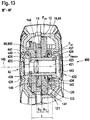
- FIG. 13 shows a section III-III 'through the cutting device 10 and the Schneidelementage 400.
- the first and the second cutting element 12, 14 are indirectly via a arranged along the rotation axis 420 shaft connected.
- the shaft forms a pivot 42 for the cutting elements 12, 14.
- the shaft is formed at least by a connecting element 421.
- On the connecting element 421, a spacer element 423 is further arranged.
- the spacer element 423 serves at least the axial, in the present case also the radial spacing of the connecting element 421 to the cutting elements 12, 14.
- the spacer element 423 can be fixed to the connecting element 421 via a securing element 430.
- the connecting element 421 may also be formed integrally with the spacer element 423.
- the connecting element 421 is designed as a screw.
- the screw can be removed and advantageously removed together with the spacer element 423 from the cutting device 10 or the handle housing 44.
- the spacer element 423 is part of a control device 422, which independently of a clamping force F clamping of the connecting element 421 causes a defined contact pressure F prerpr the cutting elements 12, 14 to each other in the direction of the axis of rotation 420.
- the cutting elements 12, 14 have through bores 120, 140 in the rotational axis direction 420, through which the connecting element 421 protrudes.
- the radial surfaces of the through bores 120, 140 form bearing surfaces, which are arranged on a corresponding bearing surface of the spacer element 423 or a sleeve radially surrounding the connecting element 421.
- the spacer element 423 sets at least indirectly a minimum distance, two clamping force transmission elements in the direction of the axis of rotation 420, here in the form of the screw head 443 of the screw and in the form of an abutment 425, wherein the abutment is designed as a nut, in particular as a non-rotatably received nut with which the Screw is connected.
- This clamping force transmission elements transmit a biasing force F clamping of the connecting element 421 at least indirectly to the spacer element 423.
- At least one axial position of the two cutting elements 12, 14 along the axis of rotation or a frictional force between the cutting elements 12, 14, which occurs when pivoting them to each other, regardless of a tightening torque of the Connection element 423 or regardless of a further influencing variable, are set.
- a longitudinal extension I of the spacer element 423 in the direction of the axis of rotation 420 allows a relative movement of the cutting elements 12, 14 in particular a pivoting movement of the cutting elements 12, 14 to each other. It advantageously corresponds at least to the sum of the width dimensions b 1 , b 2 of the two cutting elements 12, 14 along the axis of rotation 420.
- control device may have an elastic element 424 such that the cutting elements 12, 14 act on one another with a defined axial force or clamping force F clamping along the axis of rotation 420.
- the elastic element 424 is designed as a spring, in particular as a compression spring, particularly preferably as a wave spring.
- the elastic member 424 is indirectly disposed between an axial surface 122 of the first cutting element 12 and a radial shoulder 426 of the spacer element 423.
- the elastic member is disposed between the axial surface 122 of the first cutting element 12 and a locking ring 427.
- the locking ring 427 is supported on the shoulder 426 of the spacer element 423. Furthermore, the locking ring 427 is also supported on the handle housing 44.
- the force with which the elastic member is compressed 424 corresponds to the axial force F ax and acts as a pressing force F on or as pressure or normal force between the two cutting elements 12, 14.
- the elastic member 424 a friction force between the cutting elements 12, 14 one.
- a basic operating force for closing the cutting device 10 can be determined.
- a basic distance between the cutting elements 12, 14 can be adjusted. Irrespective of the production width-within a tolerance band-of the cutting elements 12, 14, the contact pressure F on the cutting elements 12, 14 remains almost constant due to the spring constant of the elastic element 424. Further tolerances of the cutting element holder 400 can be compensated.
- a sheet of paper as well as a branch are cut by the cutter 10, since the kerf can adapt to the given by the clippings 11 requirement.
- An exchange of the second cutting element 14 is possible without readjusting the clamping force or a tightening torque of the screw or a variation of intermediate elements. Regardless of the clamping force or the tightening torque of the connecting element 423 or the screw, the contact pressure F on between the cutting elements 12, 14 remains almost constant.
- the corrugated spring advantageously has an outer diameter in the range of 20 mm and an inner diameter in the range of 15 mm.
- a free axial length of the corrugated spring is advantageously less than 5 mm, in particular 3.25 mm.
- the clamping force of the wave spring is advantageously 15 to 25 N, with a compressed length of 1.1 to 1.5 mm.
- the securing ring 427 is axially supported on the handle housing 44.
- F ax of the spring or a contact pressure F at at least the first cutting element 12 is maintained.
- the second cutting element 14 to be exchanged can at least be positioned without connecting element 421 and / or is secured against accidental falling out of the cutting device 10.
- the first, in particular, fixed cutting element 12 is also transversely displaceable, that is to say displaceable in the direction of the axis of rotation 420. It is secured in the direction of rotation about the axis of rotation by positive locking elements. These were based on corresponding form-fitting elements in the first grip element 16.
- the corresponding positive-locking elements are connecting elements for connecting the grip shells of the first grip element 16.
- the elastic element 424 also serves as an overload protection element of the cutting device 10. It prevents plastic deformation of the cutting elements 12, 14 during operation of the cutting device 10.
- a threshold value F ax is set, from which the Cutting element 10 gape may.
- the elastic element yields to a stop element 442 at least until the axial stop of the second cutting element 14, thus allowing at least slight axial displacement and / or tilting within the first grip element 16 or along the axis of rotation 420 elastic behavior and the desired gap when exceeding a defined threshold can be adjusted via the spring force of the elastic element 424 and the arrangement of the control device 422.
- the control device 422 comprises at least the connecting element 421, the spacer element 423, the securing ring 427 and the elastic element 424.
- abutment 425 of the connecting element 421 in the form of the nut is firmly received in the handle housing 44 of the cutting device 10. About a hexagonal positive locking element 428 it is recorded against rotation. A lid 429 which is connected to the handle housing 44 secures the nut axially, so that it is positioned on the cutting device 10 even when the connecting element 421 is removed.
- a sliding member 440 is further arranged in the form of a sliding ring or a sliding disk.
- the sliding disk is at least one fixing element 441 rotatably connected to the handle housing 44. Further, the sliding member 440 is also disposed between the spacer member 423 and formed as a screw nut abutment 425.
- the abutment is axially secured between the sliding member 440 and the cover 429, in particular upon removal of the connecting member 421. Further, the sliding member 440 decouples a potential rotational movement of the spacer member 423 from the abutment 425.
- the control device 422 can be secured against rotation at one or more points at least indirectly with the handle housing 44 and / or the stationary first cutting element 12, so that the relative movement of the lever 80 or first cutting element 12 does not lead to an unwanted release of the connecting element 421.
- the slider, the abutment 425 and / or the spacer element 423 against rotation on the handle housing 44 are added.
- a thickness of the first cutting element 12 is advantageously 4 mm.
- a thickness of the second cutting element 14 is advantageously 3.5 mm at its thickest point.
- a thickness of the lever 80 is advantageously 3.5 mm.
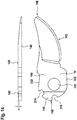
- FIG. 14 shows a cutting element, which is formed as the second cutting element 14 in a plan view, and a side view.
- the second cutting element 14 has a blade 143.
- the second cutting element 14 is an exchangeable cutting element for the cutting device 10.
- the second cutting element 14 has a tip 146 and an end 148 opposite the tip 146. In the region of the end 148, the second cutting element 14 has a recesses 214.
- the recess 214 serves as a receptacle for a locking element 210 of the blocking device 202 of the cutting device 10 for blocking a movement of the cutting elements 12, 14 to each other.
- the second cutting element 14 has the positive-locking element 216, which is designed as a counter-latching recess for the latching nose 220 of the lever 80 of the cutting device 10.
- the form-fit element 216 serves to transmit radial forces of the grip element 18, in particular via the lever 80, about the pivot 42 of the cutting device 10.
- the end 148 of the second cutting element 14 is also at least partially rounded.
- the insertion aid 144 is chamfered with respect to a sectional plane formed by the cut surface 145 of the second cutting element 14, but may also be round, in particular spherical.
- the insertion aid 144 extends substantially from the center of the receptacle 142 in the radial direction to the end 148 of the second cutting element 14.
- a thickness of the second cutting element 14 decreases in the region of the insertion aid 144 in the direction of the end 148. The thickness decreases from around 3.5 mm to 2.7 mm.
- a leg length of the inclined surface is advantageously 9 mm.
- the angle ⁇ of the inclined surface is advantageously less than 30 °, in particular less than 15 ° and very particularly preferably about 5 °.
- the support surface 149 is for positive locking Connection provided with the lever 80. It is planar and oriented normal to the direction of the recess 142 or normal to the direction of a rotation axis 420 of the secateurs 10.
- the opposite cut surface 145 is formed to slide along the first cutting element 12. It pivots slidably along the first cutting element 12 about the axis of rotation 420 and the pivot 42nd
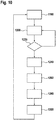
- FIG. 10 a method of operating the cutting apparatus 10 will be described ( FIG. 10 ).
- an operation of the cutting device is possible only when the blocking device is in the second position.
- a charging operation of the cutting device is not provided in this second position.
- the cutting device 10 is constantly in an operating mode. As soon as the switch 72 is closed, the control unit 52 activates the drive motor 20.
- the cutting device 10 has, in particular, an additional operating switch by means of which the cutting device 10 can be activated and deactivated.
- the cutting device 10 itself can be activated, for example, by a defined closing and / or opening sequence of the cutting device 10. A deactivation would be conceivable, for example, as a function of time.
- step 1180 If an operator wants to perform a cutting operation during operation, such as severing a branch, he must position the cut material 11 to be cut between the cutting elements 12, 14 of the cutting device 10. Subsequently, the cutting elements 12, 14, in particular as in a conventional secateurs, by squeezing the handle members 16, 18 relative to each other, be closed. The handle members 16, 18 are manually compressed by an operator in a step 1180. If the spring force of the force sensor 40 is not exceeded, the switch 72 outputs no signal. In step 1200, the control unit 52 monitors a signal from the force sensor 40 or switch 72. The control unit 52 thus monitors one for a cutting operation required force. The control unit 52 checks whether the switch 72 of the force sensor 40 is open or closed.
- step 1200 is repeated in the following branch 1220.
- the grip elements 16, 18 are manually pivoted against each other by an operator.
- the cable 34 is wound on the winch 32 by means of the return unit 31 and the spring element 36, respectively. Since a force acts on the clutch unit 22 from an output side, the clutch unit 22 is in an open state. The winch 32 can therefore be rotated without a resistance of the gear unit 38 and the drive unit 20. The cable 34 is held in tension by the spring element 36 in this state.
- the gripping elements 16, 18 are pushed apart by means of the opening spring 50 and the cutting device 10 is opened.
- the cable 34 is unwound from the winch 32 against the spring force of the spring element 36.
- the cutting device 10 can be used in a manual mode, wherein the drive unit 20 remains deactivated even if a force defined by the force sensor 40 is exceeded. There is no activation of the drive unit 20, whereby the coupling unit 22 remains open.
- the cutting device 10 is used in a assisted mode.
- a change from a manual mode to a supported mode is always done during a cutting process.
- the grip elements 16, 18 are manually pivoted against each other by an operator. If a hard clippings 11 cut, The handle elements 16, 18 must be pressed against each other with high force by an operator. If such a high force is applied that the switch 72 closes a spring force F gs when it overcomes, this is sensed by the control unit 52. The control unit 52 then activates the drive unit 20.
- the drive unit 20 is activated via the control unit 52 in a step 1240.
- the drive unit 20 is therefore connected to a locking mechanism of the cutting device 10 when exceeding a defined operator force.
- the drive unit 20 then drives the inner rotary element 46 of the coupling unit 22 via the gear unit 38.
- the drive unit 20 is driven in the drive direction 41.
- the coupling unit 22 is closed and drives the winch 32 at.
- the rope 34 is wound on the winch 32.
- the grip elements 16, 18 are now compressed or contracted in addition to an operator force F user by a drive force F as .
- the drive unit 20 is acted upon in this operating state, the cutting elements 12, 14, with a partial manual movement, with an additional force.
- the driving force F as acts on the cable 34 via the winch 32.
- the driving force F as acts here via the cable 34 on the lever 80. If the operating force F user continues to be greater than a force defined by the force sensor 40 required for closing the switch 72, the manual movement is provided by the driving force F to continue to support. If, on the other hand, the operating force F user leaves such that the switch 72 opens, the drive unit 20 stops in a step 1260. Stopping the drive unit 20 in step 1260 can also be achieved if the two gripping elements 16, 18 are closed or closed Spacing element 630 touch or an object 17 between the handle members 16, 18 is arranged, which also falls below a force defined by the force sensor 40, which is required to close the switch 72.
- the operating force F user can no longer act on the force sensor 40 in this state, since the driving force F as acts via the cable 34 on the lever 80 and moves it to its starting position in which the switch 72 is open.
- the drive unit 20 is then briefly driven in a counter rotating direction 410 in a step 1280 in order to open the clutch unit 22.
- the brake element 28 brakes the cage 26, the clamp body 24 no longer clamp the outer with the inner rotary member 46, 48.
- This direction reversal of the drive unit 20 and the drive of the drive unit 20 in the counter drive direction 410 this may be short-term, for example, less than 100 milliseconds, in particular 40 milliseconds.
- the drive unit 20 is deactivated in a step 1300. After deactivation of the drive unit 20, the procedure can be started from the beginning.
- the coupling unit 22 can decouple the drive unit 20 automatically in the absence of rotational movement.
- the cutting device 10 when a rotational movement of the drive unit 20 stops, in principle, at least partially opened by the opening spring 50 while the winch 32 are partially rotated against the cable 34 against a drive direction 41 of the drive unit 20.
- a rotation of the inner rotary member 46 can also take place to the outer rotary member 48 of the coupling unit 22 and the coupling unit 22 are opened.
- another method for opening the coupling unit 22 would be conceivable.
- the voltage monitoring device that monitors the voltage of the battery 20 may be inherently configured with the controller 52 that monitors or regulates the power supply from the battery to the motor.
- Fig. 16 shows a representation of the work area map of the motor 20 and the drive unit.
- the current (I) is plotted against the voltage (U).
- a work area 1000 is delimited from a stable area 1002 by the non-linear engine stall curve 1004.
- Voltage values from 3.3 V to 4.2 V are plotted on the X-axis as an example.
- the current I of the hatched area 1000 and 1002 corresponds to 18 A by way of example. If the motor 20 is subjected to 18 A between the exemplary 3.3 V and 3.9 V, the motor 20 comes to a standstill, with all the negative consequences.
- the maximum current output I of the battery 54, 58 or battery cell or energy storage device is limited to the motor 20 in response to a battery voltage V decreasing by discharge, in particular to avoid a motor stall.
- the application of power to the motor over the entire range of use or voltage application range of the battery 54, 58 or of the rechargeable battery can be ensured here by way of example as 3.3 V to 4.2 V stable.
- the hand tool machine may also have a temperature monitoring device, not shown (on the motor 20 or in the controller 52).
- the temperature monitoring device can limit the maximum current output as a function of the temperature.
- the engine stall curve 1004 shifts by way of example at lower engine temperatures to higher maximum current values, cf.
- Engine stall curve 1006 at lower (engine) temperatures. Respectively. conversely, at higher temperature, the maximum current output I is more limited.
- a further mode of operation of the power tool or cutting device 10 is presented, wherein the maximum current output I is throttled to an average value.
- fully charged battery here, for example, 4.2 V not the maximum current of 18 A possible here used, but the current output capped at 16 A.
- Fig. 19 a further mode of operation of the power tool or cutting device 10 is presented, wherein the maximum current output I is throttled to a lower value.
- 3.3V to 4.2V is not the average or maximum current from here 14 A to 18 A used, but the current output at 11 A capped.
- a hand tool in particular a cutting device 10, comprising a DC motor 20, a particular rechargeable battery 54,58 or accumulator, which energizes the motor 20, further comprising a voltage monitoring device (inherent with the controller 52 trained), which monitors the voltage of the battery 20 and a control or regulating device 52 which monitors or regulates the power supply from the battery 54,58 to the motor 20.
- the control or regulating device 52 drives the motor 20, in particular at least for a short time, in particular a few milliseconds, when the battery 54, 58 is charged via the charging interface 211 or if the handheld power tool is loaded with a charging device (not shown, but here a USB Cable). This will give the user feedback that the loading process has started or ended.
- An additional charging indication 200 may potentially be omitted, but need not.
- this performs a functional test of the power tool (wiring, battery 54,58, motor 20, control or regulation 52 are intact). The user is immediately in the picture or informed that the hand tool is in principle functional. Due to the limitation of the drive time there is also no risk of injury, particularly preferably in a relatively slow-moving cutting device, such as pruning shears.
- an opening of the cutting device 10 is ensured by the blocking device 202 in this case anyway. The brief admission for only milliseconds but are possible by a corresponding game in the blocking device 202. If the blocking device 202 is engaged, and thus the charging interface 211 is released, this functional test is carried out, without danger.
- the clutch 31 is released as soon as the engine is driven.
- the clutch is released and the Scissors are released.
- the cutting device 10 is not stored under load or tension. Jamming can be solved safely.
- the self-switching coupling unit 31 is provided for this purpose, which is provided in at least one operating state in which the drive unit 20 is deactivated to decouple the drive unit 20.
Landscapes
- Life Sciences & Earth Sciences (AREA)
- Forests & Forestry (AREA)
- Engineering & Computer Science (AREA)
- Biodiversity & Conservation Biology (AREA)
- Ecology (AREA)
- Environmental Sciences (AREA)
- Power Engineering (AREA)
- Mechanical Engineering (AREA)
- Harvester Elements (AREA)
- Charge And Discharge Circuits For Batteries Or The Like (AREA)
- Scissors And Nippers (AREA)
Applications Claiming Priority (1)
| Application Number | Priority Date | Filing Date | Title |
|---|---|---|---|
| DE102018201159.1A DE102018201159A1 (de) | 2018-01-25 | 2018-01-25 | Handwerkzeugmaschine |
Publications (3)
| Publication Number | Publication Date |
|---|---|
| EP3552478A2 true EP3552478A2 (fr) | 2019-10-16 |
| EP3552478A3 EP3552478A3 (fr) | 2019-11-06 |
| EP3552478B1 EP3552478B1 (fr) | 2023-04-05 |
Family
ID=65033480
Family Applications (1)
| Application Number | Title | Priority Date | Filing Date |
|---|---|---|---|
| EP19152041.0A Active EP3552478B1 (fr) | 2018-01-25 | 2019-01-16 | Machine-outil portative |
Country Status (3)
| Country | Link |
|---|---|
| EP (1) | EP3552478B1 (fr) |
| CN (1) | CN110073829B (fr) |
| DE (1) | DE102018201159A1 (fr) |
Family Cites Families (17)
| Publication number | Priority date | Publication date | Assignee | Title |
|---|---|---|---|---|
| DE102004051913A1 (de) * | 2004-08-09 | 2006-02-23 | Robert Bosch Gmbh | Akkuschrauber |
| EP1805863B1 (fr) * | 2004-10-18 | 2013-06-26 | Black & Decker, Inc. | Systeme electrique sans fil |
| JP4096951B2 (ja) * | 2005-03-28 | 2008-06-04 | 松下電工株式会社 | 電気機器 |
| DE102009000102A1 (de) * | 2009-01-09 | 2010-07-15 | Hilti Aktiengesellschaft | Steuerungsverfahren für einen Akkumulator und eine Handwerkzeugmaschine |
| CN101618720B (zh) * | 2009-08-05 | 2012-05-23 | 奇瑞汽车股份有限公司 | 一种混合动力汽车整车控制器的控制方法 |
| CN101699697A (zh) * | 2009-11-13 | 2010-04-28 | 江苏科技大学 | 一种带有蜂鸣器的电瓶充电器及其控制方法 |
| DE102012201547A1 (de) * | 2012-02-02 | 2013-08-08 | Panasonic Corporation | Kabelloses Ladesystem mit Effizienzanzeige |
| JP2014054703A (ja) * | 2012-09-13 | 2014-03-27 | Panasonic Corp | 電動工具 |
| JP6100003B2 (ja) * | 2013-02-01 | 2017-03-22 | 株式会社マキタ | 電動機械器具、及びその本体 |
| JP6029508B2 (ja) * | 2013-03-26 | 2016-11-24 | 株式会社ケーヒン | 車両用電子制御装置 |
| EP2873491A1 (fr) * | 2013-11-15 | 2015-05-20 | HILTI Aktiengesellschaft | Correction de tension à basse température pour prévenir les interruptions d'alimentation dues aux sous-tensions pour outillage électroportatif alimenté par batterie |
| EP3135437A4 (fr) * | 2014-04-24 | 2017-10-04 | Positec Power Tools (Suzhou) Co., Ltd | Outil électrique, ainsi que dispositif, système et procédé permettant de collecter des informations à distance concernant l'outil électrique |
| CN104360191B (zh) * | 2014-11-14 | 2017-10-24 | 惠州Tcl移动通信有限公司 | 一种充电器插入拔出的检测装置及检测方法 |
| DE102014019419A1 (de) * | 2014-12-22 | 2016-06-23 | GM Global Technology Operations LLC (n. d. Ges. d. Staates Delaware) | Verfahren und Diagnoseeinrichtung zur Überprüfung von Hochdrucktankventilen, Hochdrucktanksystem und Kraftfahrzeug mit einem Hochdrucktanksystem |
| US9659468B2 (en) * | 2015-09-16 | 2017-05-23 | Immersion Corporation | Haptic feedback in a haptically noisy environment |
| DE102016211978A1 (de) * | 2016-06-30 | 2018-01-04 | Robert Bosch Gmbh | Schneidelement für eine Gartenschere |
| DE102016211975A1 (de) * | 2016-06-30 | 2018-01-04 | Robert Bosch Gmbh | Schneidvorrichtung |
-
2018
- 2018-01-25 DE DE102018201159.1A patent/DE102018201159A1/de not_active Withdrawn
-
2019
- 2019-01-16 EP EP19152041.0A patent/EP3552478B1/fr active Active
- 2019-01-25 CN CN201910074515.9A patent/CN110073829B/zh active Active
Non-Patent Citations (1)
| Title |
|---|
| None |
Also Published As
| Publication number | Publication date |
|---|---|
| CN110073829B (zh) | 2023-06-13 |
| EP3552478B1 (fr) | 2023-04-05 |
| CN110073829A (zh) | 2019-08-02 |
| EP3552478A3 (fr) | 2019-11-06 |
| DE102018201159A1 (de) | 2019-07-25 |
Similar Documents
| Publication | Publication Date | Title |
|---|---|---|
| EP3262923B1 (fr) | Dispositif de coupe | |
| EP3400788B1 (fr) | Dispositif de coupe | |
| US11672208B2 (en) | Cutting device | |
| DE102016211974B4 (de) | Schneidvorrichtung | |
| DE102015013645B3 (de) | Abseilgerät | |
| DE202011052137U1 (de) | Kraftwerkzeug mit einer automatischen Drehzahlregelungsvorrichtung | |
| DE102016211973A1 (de) | Blockiervorrichtung | |
| DE102010009917A1 (de) | Schraubvorsatz und damit ausgestattetes Schraubgerät | |
| DE102015207151A1 (de) | Befestigungsmittel für Handwerkzeugmaschine | |
| EP3516947B1 (fr) | Dispositif de coupe | |
| DE102018251743A1 (de) | Schneidvorrichtung | |
| DE102016211976A1 (de) | Schneidvorrichtung | |
| DE102016211978A1 (de) | Schneidelement für eine Gartenschere | |
| EP3552478B1 (fr) | Machine-outil portative | |
| JP7682243B2 (ja) | 切断装置 | |
| DE102016211972A1 (de) | Kontrollvorrichtung | |
| EP4480650B1 (fr) | Coupe-bordures, ensemble d'accouplement associé et utilisation associée | |
| DE102009015822B3 (de) | Heckenschere | |
| DE19837049C2 (de) | Spindelmäher | |
| DE102009015821B4 (de) | Heckenschere | |
| DE19728712A1 (de) | Rotationsbehandlungsgerät für Körperpflege |
Legal Events
| Date | Code | Title | Description |
|---|---|---|---|
| PUAI | Public reference made under article 153(3) epc to a published international application that has entered the european phase |
Free format text: ORIGINAL CODE: 0009012 |
|
| STAA | Information on the status of an ep patent application or granted ep patent |
Free format text: STATUS: THE APPLICATION HAS BEEN PUBLISHED |
|
| PUAL | Search report despatched |
Free format text: ORIGINAL CODE: 0009013 |
|
| AK | Designated contracting states |
Kind code of ref document: A2 Designated state(s): AL AT BE BG CH CY CZ DE DK EE ES FI FR GB GR HR HU IE IS IT LI LT LU LV MC MK MT NL NO PL PT RO RS SE SI SK SM TR |
|
| AX | Request for extension of the european patent |
Extension state: BA ME |
|
| AK | Designated contracting states |
Kind code of ref document: A3 Designated state(s): AL AT BE BG CH CY CZ DE DK EE ES FI FR GB GR HR HU IE IS IT LI LT LU LV MC MK MT NL NO PL PT RO RS SE SI SK SM TR |
|
| AX | Request for extension of the european patent |
Extension state: BA ME |
|
| RIC1 | Information provided on ipc code assigned before grant |
Ipc: A01G 3/037 20060101AFI20191001BHEP Ipc: B25F 5/02 20060101ALI20191001BHEP Ipc: H02H 7/18 20060101ALI20191001BHEP Ipc: B26B 15/00 20060101ALI20191001BHEP |
|
| RAP1 | Party data changed (applicant data changed or rights of an application transferred) |
Owner name: ROBERT BOSCH GMBH |
|
| STAA | Information on the status of an ep patent application or granted ep patent |
Free format text: STATUS: REQUEST FOR EXAMINATION WAS MADE |
|
| 17P | Request for examination filed |
Effective date: 20200506 |
|
| RBV | Designated contracting states (corrected) |
Designated state(s): AL AT BE BG CH CY CZ DE DK EE ES FI FR GB GR HR HU IE IS IT LI LT LU LV MC MK MT NL NO PL PT RO RS SE SI SK SM TR |
|
| GRAP | Despatch of communication of intention to grant a patent |
Free format text: ORIGINAL CODE: EPIDOSNIGR1 |
|
| STAA | Information on the status of an ep patent application or granted ep patent |
Free format text: STATUS: GRANT OF PATENT IS INTENDED |
|
| INTG | Intention to grant announced |
Effective date: 20221027 |
|
| RIN1 | Information on inventor provided before grant (corrected) |
Inventor name: NAGY, JANOS Inventor name: BIHARI, IMRE Inventor name: SEPSI, KRISZTIAN |
|
| GRAS | Grant fee paid |
Free format text: ORIGINAL CODE: EPIDOSNIGR3 |
|
| GRAA | (expected) grant |
Free format text: ORIGINAL CODE: 0009210 |
|
| STAA | Information on the status of an ep patent application or granted ep patent |
Free format text: STATUS: THE PATENT HAS BEEN GRANTED |
|
| AK | Designated contracting states |
Kind code of ref document: B1 Designated state(s): AL AT BE BG CH CY CZ DE DK EE ES FI FR GB GR HR HU IE IS IT LI LT LU LV MC MK MT NL NO PL PT RO RS SE SI SK SM TR |
|
| REG | Reference to a national code |
Ref country code: GB Ref legal event code: FG4D Free format text: NOT ENGLISH |
|
| REG | Reference to a national code |
Ref country code: CH Ref legal event code: EP |
|
| REG | Reference to a national code |
Ref country code: AT Ref legal event code: REF Ref document number: 1557581 Country of ref document: AT Kind code of ref document: T Effective date: 20230415 |
|
| REG | Reference to a national code |
Ref country code: DE Ref legal event code: R096 Ref document number: 502019007370 Country of ref document: DE |
|
| REG | Reference to a national code |
Ref country code: IE Ref legal event code: FG4D Free format text: LANGUAGE OF EP DOCUMENT: GERMAN |
|
| P01 | Opt-out of the competence of the unified patent court (upc) registered |
Effective date: 20230509 |
|
| REG | Reference to a national code |
Ref country code: LT Ref legal event code: MG9D |
|
| REG | Reference to a national code |
Ref country code: NL Ref legal event code: MP Effective date: 20230405 |
|
| PG25 | Lapsed in a contracting state [announced via postgrant information from national office to epo] |
Ref country code: NL Free format text: LAPSE BECAUSE OF FAILURE TO SUBMIT A TRANSLATION OF THE DESCRIPTION OR TO PAY THE FEE WITHIN THE PRESCRIBED TIME-LIMIT Effective date: 20230405 |
|
| PG25 | Lapsed in a contracting state [announced via postgrant information from national office to epo] |
Ref country code: SE Free format text: LAPSE BECAUSE OF FAILURE TO SUBMIT A TRANSLATION OF THE DESCRIPTION OR TO PAY THE FEE WITHIN THE PRESCRIBED TIME-LIMIT Effective date: 20230405 Ref country code: PT Free format text: LAPSE BECAUSE OF FAILURE TO SUBMIT A TRANSLATION OF THE DESCRIPTION OR TO PAY THE FEE WITHIN THE PRESCRIBED TIME-LIMIT Effective date: 20230807 Ref country code: NO Free format text: LAPSE BECAUSE OF FAILURE TO SUBMIT A TRANSLATION OF THE DESCRIPTION OR TO PAY THE FEE WITHIN THE PRESCRIBED TIME-LIMIT Effective date: 20230705 Ref country code: ES Free format text: LAPSE BECAUSE OF FAILURE TO SUBMIT A TRANSLATION OF THE DESCRIPTION OR TO PAY THE FEE WITHIN THE PRESCRIBED TIME-LIMIT Effective date: 20230405 |
|
| PG25 | Lapsed in a contracting state [announced via postgrant information from national office to epo] |
Ref country code: RS Free format text: LAPSE BECAUSE OF FAILURE TO SUBMIT A TRANSLATION OF THE DESCRIPTION OR TO PAY THE FEE WITHIN THE PRESCRIBED TIME-LIMIT Effective date: 20230405 Ref country code: PL Free format text: LAPSE BECAUSE OF FAILURE TO SUBMIT A TRANSLATION OF THE DESCRIPTION OR TO PAY THE FEE WITHIN THE PRESCRIBED TIME-LIMIT Effective date: 20230405 Ref country code: LV Free format text: LAPSE BECAUSE OF FAILURE TO SUBMIT A TRANSLATION OF THE DESCRIPTION OR TO PAY THE FEE WITHIN THE PRESCRIBED TIME-LIMIT Effective date: 20230405 Ref country code: LT Free format text: LAPSE BECAUSE OF FAILURE TO SUBMIT A TRANSLATION OF THE DESCRIPTION OR TO PAY THE FEE WITHIN THE PRESCRIBED TIME-LIMIT Effective date: 20230405 Ref country code: IS Free format text: LAPSE BECAUSE OF FAILURE TO SUBMIT A TRANSLATION OF THE DESCRIPTION OR TO PAY THE FEE WITHIN THE PRESCRIBED TIME-LIMIT Effective date: 20230805 Ref country code: HR Free format text: LAPSE BECAUSE OF FAILURE TO SUBMIT A TRANSLATION OF THE DESCRIPTION OR TO PAY THE FEE WITHIN THE PRESCRIBED TIME-LIMIT Effective date: 20230405 Ref country code: GR Free format text: LAPSE BECAUSE OF FAILURE TO SUBMIT A TRANSLATION OF THE DESCRIPTION OR TO PAY THE FEE WITHIN THE PRESCRIBED TIME-LIMIT Effective date: 20230706 Ref country code: AL Free format text: LAPSE BECAUSE OF FAILURE TO SUBMIT A TRANSLATION OF THE DESCRIPTION OR TO PAY THE FEE WITHIN THE PRESCRIBED TIME-LIMIT Effective date: 20230405 |
|
| PG25 | Lapsed in a contracting state [announced via postgrant information from national office to epo] |
Ref country code: FI Free format text: LAPSE BECAUSE OF FAILURE TO SUBMIT A TRANSLATION OF THE DESCRIPTION OR TO PAY THE FEE WITHIN THE PRESCRIBED TIME-LIMIT Effective date: 20230405 |
|
| REG | Reference to a national code |
Ref country code: DE Ref legal event code: R097 Ref document number: 502019007370 Country of ref document: DE |
|
| PG25 | Lapsed in a contracting state [announced via postgrant information from national office to epo] |
Ref country code: SK Free format text: LAPSE BECAUSE OF FAILURE TO SUBMIT A TRANSLATION OF THE DESCRIPTION OR TO PAY THE FEE WITHIN THE PRESCRIBED TIME-LIMIT Effective date: 20230405 |
|
| PG25 | Lapsed in a contracting state [announced via postgrant information from national office to epo] |
Ref country code: SM Free format text: LAPSE BECAUSE OF FAILURE TO SUBMIT A TRANSLATION OF THE DESCRIPTION OR TO PAY THE FEE WITHIN THE PRESCRIBED TIME-LIMIT Effective date: 20230405 Ref country code: SK Free format text: LAPSE BECAUSE OF FAILURE TO SUBMIT A TRANSLATION OF THE DESCRIPTION OR TO PAY THE FEE WITHIN THE PRESCRIBED TIME-LIMIT Effective date: 20230405 Ref country code: RO Free format text: LAPSE BECAUSE OF FAILURE TO SUBMIT A TRANSLATION OF THE DESCRIPTION OR TO PAY THE FEE WITHIN THE PRESCRIBED TIME-LIMIT Effective date: 20230405 Ref country code: EE Free format text: LAPSE BECAUSE OF FAILURE TO SUBMIT A TRANSLATION OF THE DESCRIPTION OR TO PAY THE FEE WITHIN THE PRESCRIBED TIME-LIMIT Effective date: 20230405 Ref country code: DK Free format text: LAPSE BECAUSE OF FAILURE TO SUBMIT A TRANSLATION OF THE DESCRIPTION OR TO PAY THE FEE WITHIN THE PRESCRIBED TIME-LIMIT Effective date: 20230405 Ref country code: CZ Free format text: LAPSE BECAUSE OF FAILURE TO SUBMIT A TRANSLATION OF THE DESCRIPTION OR TO PAY THE FEE WITHIN THE PRESCRIBED TIME-LIMIT Effective date: 20230405 |
|
| PLBE | No opposition filed within time limit |
Free format text: ORIGINAL CODE: 0009261 |
|
| STAA | Information on the status of an ep patent application or granted ep patent |
Free format text: STATUS: NO OPPOSITION FILED WITHIN TIME LIMIT |
|
| 26N | No opposition filed |
Effective date: 20240108 |
|
| PG25 | Lapsed in a contracting state [announced via postgrant information from national office to epo] |
Ref country code: SI Free format text: LAPSE BECAUSE OF FAILURE TO SUBMIT A TRANSLATION OF THE DESCRIPTION OR TO PAY THE FEE WITHIN THE PRESCRIBED TIME-LIMIT Effective date: 20230405 |
|
| PG25 | Lapsed in a contracting state [announced via postgrant information from national office to epo] |
Ref country code: SI Free format text: LAPSE BECAUSE OF FAILURE TO SUBMIT A TRANSLATION OF THE DESCRIPTION OR TO PAY THE FEE WITHIN THE PRESCRIBED TIME-LIMIT Effective date: 20230405 Ref country code: IT Free format text: LAPSE BECAUSE OF FAILURE TO SUBMIT A TRANSLATION OF THE DESCRIPTION OR TO PAY THE FEE WITHIN THE PRESCRIBED TIME-LIMIT Effective date: 20230405 |
|
| PG25 | Lapsed in a contracting state [announced via postgrant information from national office to epo] |
Ref country code: MC Free format text: LAPSE BECAUSE OF FAILURE TO SUBMIT A TRANSLATION OF THE DESCRIPTION OR TO PAY THE FEE WITHIN THE PRESCRIBED TIME-LIMIT Effective date: 20230405 |
|
| PG25 | Lapsed in a contracting state [announced via postgrant information from national office to epo] |
Ref country code: MC Free format text: LAPSE BECAUSE OF FAILURE TO SUBMIT A TRANSLATION OF THE DESCRIPTION OR TO PAY THE FEE WITHIN THE PRESCRIBED TIME-LIMIT Effective date: 20230405 |
|
| REG | Reference to a national code |
Ref country code: CH Ref legal event code: PL |
|
| PG25 | Lapsed in a contracting state [announced via postgrant information from national office to epo] |
Ref country code: LU Free format text: LAPSE BECAUSE OF NON-PAYMENT OF DUE FEES Effective date: 20240116 |
|
| PG25 | Lapsed in a contracting state [announced via postgrant information from national office to epo] |
Ref country code: LU Free format text: LAPSE BECAUSE OF NON-PAYMENT OF DUE FEES Effective date: 20240116 |
|
| PG25 | Lapsed in a contracting state [announced via postgrant information from national office to epo] |
Ref country code: BE Free format text: LAPSE BECAUSE OF NON-PAYMENT OF DUE FEES Effective date: 20240131 |
|
| PG25 | Lapsed in a contracting state [announced via postgrant information from national office to epo] |
Ref country code: CH Free format text: LAPSE BECAUSE OF NON-PAYMENT OF DUE FEES Effective date: 20240131 |
|
| PG25 | Lapsed in a contracting state [announced via postgrant information from national office to epo] |
Ref country code: CH Free format text: LAPSE BECAUSE OF NON-PAYMENT OF DUE FEES Effective date: 20240131 Ref country code: BE Free format text: LAPSE BECAUSE OF NON-PAYMENT OF DUE FEES Effective date: 20240131 |
|
| REG | Reference to a national code |
Ref country code: BE Ref legal event code: MM Effective date: 20240131 |
|
| PG25 | Lapsed in a contracting state [announced via postgrant information from national office to epo] |
Ref country code: BG Free format text: LAPSE BECAUSE OF FAILURE TO SUBMIT A TRANSLATION OF THE DESCRIPTION OR TO PAY THE FEE WITHIN THE PRESCRIBED TIME-LIMIT Effective date: 20230405 |
|
| PG25 | Lapsed in a contracting state [announced via postgrant information from national office to epo] |
Ref country code: BG Free format text: LAPSE BECAUSE OF FAILURE TO SUBMIT A TRANSLATION OF THE DESCRIPTION OR TO PAY THE FEE WITHIN THE PRESCRIBED TIME-LIMIT Effective date: 20230405 |
|
| PG25 | Lapsed in a contracting state [announced via postgrant information from national office to epo] |
Ref country code: IE Free format text: LAPSE BECAUSE OF NON-PAYMENT OF DUE FEES Effective date: 20240116 |
|
| PG25 | Lapsed in a contracting state [announced via postgrant information from national office to epo] |
Ref country code: IE Free format text: LAPSE BECAUSE OF NON-PAYMENT OF DUE FEES Effective date: 20240116 |
|
| REG | Reference to a national code |
Ref country code: AT Ref legal event code: MM01 Ref document number: 1557581 Country of ref document: AT Kind code of ref document: T Effective date: 20240116 |
|
| PGFP | Annual fee paid to national office [announced via postgrant information from national office to epo] |
Ref country code: DE Payment date: 20250317 Year of fee payment: 7 |
|
| PG25 | Lapsed in a contracting state [announced via postgrant information from national office to epo] |
Ref country code: AT Free format text: LAPSE BECAUSE OF NON-PAYMENT OF DUE FEES Effective date: 20240116 |
|
| PGFP | Annual fee paid to national office [announced via postgrant information from national office to epo] |
Ref country code: FR Payment date: 20250123 Year of fee payment: 7 |
|
| PGFP | Annual fee paid to national office [announced via postgrant information from national office to epo] |
Ref country code: GB Payment date: 20250123 Year of fee payment: 7 |
|
| PG25 | Lapsed in a contracting state [announced via postgrant information from national office to epo] |
Ref country code: CY Free format text: LAPSE BECAUSE OF FAILURE TO SUBMIT A TRANSLATION OF THE DESCRIPTION OR TO PAY THE FEE WITHIN THE PRESCRIBED TIME-LIMIT; INVALID AB INITIO Effective date: 20190116 |
|
| PG25 | Lapsed in a contracting state [announced via postgrant information from national office to epo] |
Ref country code: HU Free format text: LAPSE BECAUSE OF FAILURE TO SUBMIT A TRANSLATION OF THE DESCRIPTION OR TO PAY THE FEE WITHIN THE PRESCRIBED TIME-LIMIT; INVALID AB INITIO Effective date: 20190116 |
|
| PG25 | Lapsed in a contracting state [announced via postgrant information from national office to epo] |
Ref country code: TR Free format text: LAPSE BECAUSE OF FAILURE TO SUBMIT A TRANSLATION OF THE DESCRIPTION OR TO PAY THE FEE WITHIN THE PRESCRIBED TIME-LIMIT Effective date: 20230405 |