EP3552386B1 - Systèmes et procédés de relecture vidéo - Google Patents
Systèmes et procédés de relecture vidéo Download PDFInfo
- Publication number
- EP3552386B1 EP3552386B1 EP17891674.8A EP17891674A EP3552386B1 EP 3552386 B1 EP3552386 B1 EP 3552386B1 EP 17891674 A EP17891674 A EP 17891674A EP 3552386 B1 EP3552386 B1 EP 3552386B1
- Authority
- EP
- European Patent Office
- Prior art keywords
- index
- video
- target
- ptz head
- ptz
- Prior art date
- Legal status (The legal status is an assumption and is not a legal conclusion. Google has not performed a legal analysis and makes no representation as to the accuracy of the status listed.)
- Active
Links
Images


Classifications
-
- H—ELECTRICITY
- H04—ELECTRIC COMMUNICATION TECHNIQUE
- H04N—PICTORIAL COMMUNICATION, e.g. TELEVISION
- H04N5/00—Details of television systems
- H04N5/76—Television signal recording
- H04N5/91—Television signal processing therefor
- H04N5/93—Regeneration of the television signal or of selected parts thereof
-
- H—ELECTRICITY
- H04—ELECTRIC COMMUNICATION TECHNIQUE
- H04N—PICTORIAL COMMUNICATION, e.g. TELEVISION
- H04N5/00—Details of television systems
- H04N5/76—Television signal recording
- H04N5/765—Interface circuits between an apparatus for recording and another apparatus
- H04N5/77—Interface circuits between an apparatus for recording and another apparatus between a recording apparatus and a television camera
-
- G—PHYSICS
- G11—INFORMATION STORAGE
- G11B—INFORMATION STORAGE BASED ON RELATIVE MOVEMENT BETWEEN RECORD CARRIER AND TRANSDUCER
- G11B27/00—Editing; Indexing; Addressing; Timing or synchronising; Monitoring; Measuring tape travel
- G11B27/10—Indexing; Addressing; Timing or synchronising; Measuring tape travel
- G11B27/102—Programmed access in sequence to addressed parts of tracks of operating record carriers
-
- H—ELECTRICITY
- H04—ELECTRIC COMMUNICATION TECHNIQUE
- H04N—PICTORIAL COMMUNICATION, e.g. TELEVISION
- H04N5/00—Details of television systems
- H04N5/76—Television signal recording
- H04N5/91—Television signal processing therefor
-
- H—ELECTRICITY
- H04—ELECTRIC COMMUNICATION TECHNIQUE
- H04N—PICTORIAL COMMUNICATION, e.g. TELEVISION
- H04N5/00—Details of television systems
- H04N5/76—Television signal recording
- H04N5/91—Television signal processing therefor
- H04N5/92—Transformation of the television signal for recording, e.g. modulation, frequency changing; Inverse transformation for playback
- H04N5/9201—Transformation of the television signal for recording, e.g. modulation, frequency changing; Inverse transformation for playback involving the multiplexing of an additional signal and the video signal
-
- H—ELECTRICITY
- H04—ELECTRIC COMMUNICATION TECHNIQUE
- H04N—PICTORIAL COMMUNICATION, e.g. TELEVISION
- H04N9/00—Details of colour television systems
- H04N9/79—Processing of colour television signals in connection with recording
- H04N9/80—Transformation of the television signal for recording, e.g. modulation, frequency changing; Inverse transformation for playback
- H04N9/804—Transformation of the television signal for recording, e.g. modulation, frequency changing; Inverse transformation for playback involving pulse code modulation of the colour picture signal components
- H04N9/8042—Transformation of the television signal for recording, e.g. modulation, frequency changing; Inverse transformation for playback involving pulse code modulation of the colour picture signal components involving data reduction
Definitions
- This disclosure generally relates to video surveillance, and more particularly, relates to systems and methods for replaying a target scene in video surveillance.
- the logic circuits may search an index table to determine a target index position, the target index position being a position of the PTZ head stored in the index table, which is matched to the target position, wherein the index table indexes a plurality of index positions, each index position being the position of the PTZ head when the camera records a key frame of the video clip, the key frame being a frame defining a start or end point of a smooth transition in the video clip, the index table contains a plurality of index items, each index item including the index position of the PTZ head and a corresponding offset address, the offset address determining an address where the key frame is stored, and wherein the target index position of the PTZ head is determined by comparing the coordinates of each of the plurality of index positions of the PTZ head stored in the index table with the coordinates of the target position of the PTZ head and by ascertaining that the difference between the coordinates of a stored position and the coordinates of the target position is smaller than or equal to a predetermined value.
- the system may further include the camera in communication with the logic circuits, wherein the camera may include one or more video recording units mounted on one or more movable platform.
- the logic circuits may control the one or more movable platforms to locate the one or more video recording units to a position, so that the one or more video recording units can intake the target scene in the video.
- the logic circuits may obtain the position of the one or more video recording units as the target position
- flow charts are used to illustrate the operations performed by the system. It is to be expressly understood, the operations above or below may or may not be implemented in order. Conversely, the operations may be performed in inverted order, or simultaneously. Besides, one or more other operations may be added to the flowcharts, or one or more operations may be omitted from the flowchart.
- Exemplary volatile read-and-write memory may include a random-access memory (RAM).
- RAM may include a dynamic RAM (DRAM), a double date rate synchronous dynamic RAM (DDR SDRAM), a static RAM (SRAM), a thyristor RAM (T-RAM), and a zero-capacitor RAM (Z-RAM), etc.
- Exemplary ROM may include a mask ROM (MROM), a programmable ROM (PROM), an erasable programmable ROM (EPROM), an electrically erasable programmable ROM (EEPROM), a compact disk ROM (CD-ROM), and a digital versatile disk ROM, etc.
- MROM mask ROM
- PROM programmable ROM
- EPROM erasable programmable ROM
- EEPROM electrically erasable programmable ROM
- CD-ROM compact disk ROM
- digital versatile disk ROM etc.
- the PTZ head may be rotated in 180 degrees in a vertical plane. As still another example, the PTZ head may be rotated both in the horizontal plane and the vertical plane. Further, the PTZ head may also be a platform configured to perform translational motion to the PTZ camera.
- the media sever 103 may be a server (e.g., a computer or a group of computers) for storing, broadcasting, selling, renting, or providing videos.
- the media server 103 may also include an image and/or video processing electronic device (not shown) configured to process the images and/or video streams from the video source 101 using the methods introduced in the present disclosure.
- Exemplary volatile read-and-write memory may include a random-access memory (RAM), such as a dynamic RAM (DRAM), a double date rate synchronous dynamic RAM (DDR SDRAM), a static RAM (SRAM), a thyristor RAM (T-RAM), and a zero-capacitor RAM (Z-RAM).
- RAM random-access memory
- DRAM dynamic RAM
- DDR SDRAM double date rate synchronous dynamic RAM
- SRAM static RAM
- T-RAM thyristor RAM
- Z-RAM zero-capacitor RAM
- Exemplary ROM may include a mask ROM (MROM), a programmable ROM (PROM), an erasable programmable ROM (EPROM), an electrically erasable programmable ROM (EEPROM), a compact disk ROM (CD-ROM), and a digital versatile disk ROM, etc.
- MROM mask ROM
- PROM programmable ROM
- EPROM erasable programmable ROM
- EEPROM electrically era
- the transmitter 107 may transmit the video or video frames buffered in the buffer 106 to the network 112.
- the transmitter 107 may transmit video or video frames in response to instructions sent from the video provider 101, the buffer manager 105, the terminal 108, or the like, or a combination thereof.
- the transmitter 107 may spontaneously transmit video or video frames stored in the buffer 106.
- the transmitter 107 may transmit video or video frames through the network 112 to the terminal 108 though one or more network connections (wired and/or wireless).
- the terminal 108 may receive the transmitted video through the network 112.
- the terminal 108 may decode (e.g., through a video player installed on the terminal 108) the transmitted video or video frames using a decoding algorithm and display the video to a user.
- the decoding algorithm may correspond to the encoding algorithm used by the encoder 104.
- the terminal 108 may be various in forms.
- the terminal 108 may include a mobile device 109, a tablet computer 110, a laptop computer 111, or the like, or any combination thereof.
- the mobile device 109 may include, a wearable device, a mobile device, a virtual reality device, an augmented reality device, or the like, or any combination thereof.
- the wearable device may include a bracelet, footgear, eyeglasses, a helmet, a watch, clothing, a backpack, a smart accessory, or the like, or any combination thereof.
- the mobile device may include a mobile phone, a personal digital assistance (PDA), a laptop, a tablet computer, a desktop, or the like, or any combination thereof.
- PDA personal digital assistance
- the virtual reality device and/or the augmented reality device may include a virtual reality helmet, virtual reality glasses, a virtual reality patch, an augmented reality helmet, augmented reality glasses, an augmented reality patch, or the like, or any combination thereof.
- the virtual reality device and/or the augmented reality device may include a Google GlassTM, an Oculus RiftTM, a HololensTM, a Gear VRTM, etc.
- the terminal(s) 108 may be part of a processing engine.
- the network 112 may include any suitable network that can facilitate a transmission of a video provided by the video source 101 to the terminal(s) 108.
- the network 112 may be and/or include a public network (e.g., the Internet), a private network (e.g., a local area network (LAN), a wide area network (WAN)), a wired network (e.g., an Ethernet network), a wireless network (e.g., an 802.11 network, a Wi-Fi network), a cellular network (e.g., a Long Term Evolution (LTE) network), a frame relay network, a virtual private network (“VPN”), a satellite network, a telephone network, routers, hubs, switches, server computers, and/or any combination thereof.
- a public network e.g., the Internet
- a private network e.g., a local area network (LAN), a wide area network (WAN)
- a wired network e.g., an Ethernet network
- one or more of the encoder 104, buffer manager 105, buffer 106 and transmitter may be a stand-alone device, or a module integrated into the video source 101 or another stand-alone device.
- one or more of the encoder 104, buffer manager 105, buffer 106 and transmitter 107 may be integrated into the camera 102 or the media server 103.
- the encoder 104, buffer manager 105, buffer 106 and transmitter 107 may be included in a video processing engine which may communicate with the video source 101 through direct wired connection, the network 112, or another network not shown in FIG. 3A .
- the encoder 104 may be a stand-alone device (e.g., a computer or a server), while the buffer manager 105, buffer 106 and transmitter 107 may be included in another stand-alone device.
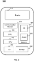
- FIG. 2 is a schematic diagram illustrating exemplary hardware and/or software components of an exemplary computing device according to some embodiments of the present disclosure.
- the computing device 200 may be the server 103, the processor of the camera 102, and/or an electronic device specialized in video or image processing.
- the encoder 104 and buffer manager 105 may also be implemented on the computing device 200.
- the computing device 200 may include a processor 222, a storage 227, an input/output (I/O) 226, and a communication port 225.
- I/O input/output
- the processor 222 may execute computer instructions (e.g., program code) and perform functions in accordance with techniques described herein.
- the processor 222 may include interface circuits and processing circuits therein.
- the interface circuits may be configured to receive electronic signals from a bus (not shown in FIG. 2 ), wherein the electronic signals encode structured data and/or instructions for the processing circuits to process.
- the processing circuits may conduct logical operations calculations, and then determine a conclusion, a result, and/or an instruction encoded as electronic signals. Then the interface circuits may send out the electronic signals from the processing circuits via the bus.
- the computer instructions may include, for example, routines, programs, objects, components, data structures, procedures, modules, and functions, which perform particular functions described herein.
- the processor 222 may include one or more hardware processors, such as a microcontroller, a microprocessor, a reduced instruction set computer (RISC), an application specific integrated circuits (ASICs), an application-specific instruction-set processor (ASIP), a central processing unit (CPU), a graphics processing unit (GPU), a physics processing unit (PPU), a microcontroller unit, a digital signal processor (DSP), a field programmable gate array (FPGA), an advanced RISC machine (ARM), a programmable logic device (PLD), any circuit or processor capable of executing one or more functions, or the like, or any combinations thereof.
- RISC reduced instruction set computer
- ASICs application specific integrated circuits
- ASIP application-specific instruction-set processor
- CPU central processing unit
- GPU graphics processing unit
- PPU physics processing unit
- DSP digital signal processor
- the I/O 226 may input and/or output signals, data, information, etc.
- the I/O 226 may include an input device and an output device.
- Examples of the input device may include a keyboard, a mouse, a touch screen, a microphone, or the like, or a combination thereof.
- Examples of the output device may include a display device, a loudspeaker, a printer, a projector, or the like, or a combination thereof.
- Examples of the display device may include a liquid crystal display (LCD), a light-emitting diode (LED)-based display, a flat panel display, a curved screen, a television device, a cathode ray tube (CRT), a touch screen, or the like, or a combination thereof.
- LCD liquid crystal display
- LED light-emitting diode
- CRT cathode ray tube
- the communication port 225 may be connected to a network (e.g., the network 112) to facilitate data communications.
- the communication port 225 may establish connections between the video source 101, the encoder 104, the buffer manager 105, the buffer 106, the transmitter 107, the terminal 108, the network 112, the network storage device 113, and/or any other component of the video processing system 100.
- the connection may be a wired connection, a wireless connection, any other communication connection that can enable data transmission and/or reception, and/or any combination of these connections.
- the wired connection may include, for example, an electrical cable, an optical cable, a telephone wire, or the like, or any combination thereof.
- FIG. 3 is a schematic diagram illustrating exemplary components of an exemplary user device according to some embodiments of the present disclosure.
- the user device 300 may include a communication platform 320, a display 310, a graphic processing unit (GPU) 330, a central processing unit (CPU) 330, an I/O port 350, a memory 360, and a storage 390.
- any other suitable component including but not limited to a system bus or a controller (not shown), may also be included in the user device 300.
- a mobile operating system 370 e.g., iOSTM, AndroidTM, Windows PhoneTM
- one or more applications 380 may be loaded into the memory 360 from the storage 390 in order to be executed by the processor 340.
- the user device 300 may be an embodiment of the terminal 108.
- the applications 380 may include a video player for receiving a video provided by the video source 101 through the network 112 and decode the received video.
- computer hardware platforms may be used as the hardware platform(s) for one or more of the elements described herein.
- a computer with user interface elements may be used to implement a personal computer (PC) or any other type of work station or terminal device.
- PC personal computer
- a computer may also act as a server if appropriately programmed.
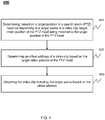
- FIG. 4 is a flow chart illustrating an exemplary process for replaying a target scene in a video clip according to some embodiments of the present disclosure.
- the process 400 may be implemented on the video processing system 100 as illustrated in FIG. 1 .
- the process 400 may be stored in a storage medium (e.g., the network storage device 113, or the storage 227 of the computing device 228) as a form of instructions, and invoked and/or executed by the media server 103.
- the operations in the process 400 presented below are intended to be illustrative. In some embodiments, the process 400 may be accomplished with one or more additional operations not described, and/or without one or more of the operations discussed. Additionally, the order in which the operations of the process 400 as illustrated in FIG. 4 and described below may not be intended to be limiting.
- the target index position may refer to an index position of the PTZ head which is matched to the target position of the PTZ head.
- a key frame may refer to a frame that defines starting points and ending points of a smooth transition in a video clip. A key frame may be created when a dramatic change to the scenes in a video clip occurs, for example, the PTZ head rotates.
- the media server 103 may determine a target index position of the PTZ head in an index item from an index table being matched to the target position of the PTZ head. During this process, the media server 103 may obtain coordinates of index positions of the PTZ head in one or more index items of an index table. In some embodiments, the media server 103 may obtain the coordinates of index positions of the PTZ head in the one or more index items one by one. After the media server 103 obtain coordinates of an index position of the PTZ head in an index item, the media server 103 may determine a difference between the coordinates of the index position of the PTZ head and coordinates of the target position of the PTZ head.
- coordinates of index positions of the PTZ head may refer to coordinates of positions of the PTZ head when the camera 102 records key frames.
- Coordinates of the target position of the PTZ head may refer to coordinates of a position of the PTZ head when the camera 102 records a frame corresponding to the target scene.
- the coordinates of the index positions of the PTZ head and the coordinates of the target position of the PTZ head may be determined in a coordinate system.
- the coordinate system may be a spherical coordinate system (e.g., longitude and latitude).
- the coordinates may be represented by a three-dimensional Cartesian coordinate system.
- the media server 103 may determine a distance between an index position of the PTZ head and the target position of the PTZ head based on coordinates of the index position of the PTZ head and coordinates of the target position of the PTZ head (i.e., the difference between the coordinates of the index position of the PTZ head and coordinates of the target position of the PTZ head).
- the media server 103 may determine that the index item includes an index position of the PTZ head being matched to the target position of the PTZ head if the distance is smaller than or equal to the first predetermined value.
- the media server 103 may determine that the index item does not include an index position being matched to the target position of the PTZ head if the distance is greater than the first predetermined value.
- the index position may refer to a position of the PTZ head when the camera 102 records the key frame.
- the index position may be represented by coordinates of the index position of the PTZ head relative to a coordinate system.
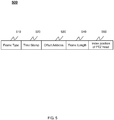
- the offset address of the video data may refer to an address where the key frame is stored.
- the offset address 530 may be a physical address relate to a storage medium (e.g., a hard disk).
- the frame length 540 may refer to a length of a key frame.
- the index position of the PTZ head position 550 may refer to a position (e.g., represented by coordinates) of the PTZ head when the camera 102 records the key frame. It should be noted that the key frames may be recorded to guarantee the detection of different scenes in a video recording process, to reduce data volumes of the index items, as well as to improve a detection efficiency.
- the media server 103 may record other types of video frames during a video recording process, which is not limited in the present disclosure.
- the determination module 710 may be configured to determine a target index position from one or more index positions, which is matched to the target position of the PTZ head.
- the target position of the PTZ head may correspond to a target scene to be replayed.
- an index position of the PTZ head is included in an index item of an index table.
- the index item may include, for example, the index position, and an offset address.
- the index item may further include a frame type, a time stamp, and a frame length.
- the video obtaining module 810 may obtain video data.
- the video obtaining module 810 may obtain the video data from a video recording device.
- the video data may include a video frame.
- the video frame may be a key frame.
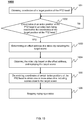
- FIG. 9 is a flow chart illustrating an exemplary process for recording a video clip according to some embodiments of the present disclosure.
- the process 900 may be implemented on the video processing system 100 as illustrated in FIG. 1 .
- the process 900 may be stored in a storage medium (e.g., the network storage device 113, or the storage 227 of the computing device 228) as a form of instructions, and invoked and/or executed by the media server 103.
- the operations in the process 900 presented below are intended to be illustrative. In some embodiments, the process 900 may be accomplished with one or more additional operations not described, and/or without one or more of the operations discussed. Additionally, the order in which the operations of the process 900 as illustrated in FIG. 9 and described below may not be intended to be limiting.
- the media server 103 may obtain current coordinates of the PTZ head (also referred to as "coordinates of index position of the PTZ head") in 903, and store the video data including the video frame in a video clip in 905. If the video frame is not a key frame, the media server 103 may store the video data including the video frame in a video clip in 905.
- the media server 103 may store the video frame in a video.
- the media server 103 may obtain coordinates of a target position of the PTZ head.
- the target position of the PTZ head may correspond to a target scene.
- the target scene may be a scene that a user may be interested in.
- aspects of the present disclosure may be illustrated and described herein in any of a number of patentable classes or context including any new and useful process, machine, manufacture, or composition of matter, or any new and useful improvement thereof. Accordingly, aspects of the present disclosure may be implemented entirely hardware, entirely software (including firmware, resident software, micro-code, etc.) or combining software and hardware implementation that may all generally be referred to herein as a "module,” “unit,” “component,” “device,” or “system.” Furthermore, aspects of the present disclosure may take the form of a computer program product embodied in one or more computer readable media having computer readable program code embodied thereon.
- Computer program code for carrying out operations for aspects of the present disclosure may be written in any combination of one or more programming languages, including an object oriented programming language such as Java, Scala, Smalltalk, Eiffel, JADE, Emerald, C++, C#, VB. NET, Python or the like, conventional procedural programming languages, such as the "C" programming language, Visual Basic, Fortran 2003, Perl, COBOL 2002, PHP, ABAP, dynamic programming languages such as Python, Ruby and Groovy, or other programming languages.
- the program code may execute entirely on the user's computer, partly on the user's computer, as a stand-alone software package, partly on the user's computer and partly on a remote computer or entirely on the remote computer or server.
Landscapes
- Engineering & Computer Science (AREA)
- Multimedia (AREA)
- Signal Processing (AREA)
- Television Signal Processing For Recording (AREA)
- Studio Devices (AREA)
Claims (13)
- Système de traitement vidéo pour relecture d'une vidéo, le système enregistrant des coordonnées de position d'une tête d'une caméra panoramique-inclinaison-zoom (102) (tête PTZ) montée sur une ou plusieurs plates-formes mobiles, le système comprenant une unité de relecture et d'enregistrement vidéo comprenant :au moins un support de stockage non transitoire (227), incluant un ensemble d'instructions pour une relecture vidéo et un enregistrement vidéo ;des circuits logiques en communication avec le au moins un support de stockage (227), dans lequel lors d'une exécution de l'ensemble d'instructions, les circuits logiques exécutent les tâches suivantes consistant à :sélectionner une position cible de la tête PTZ correspondant à une scène cible, la scène cible étant une scène dans un clip vidéo qu'un utilisateur souhaite visualiser et la position cible étant une position de la tête PTZ lorsque la caméra (102) enregistre une ou plusieurs trames correspondant à la scène cible ;sur la base de la position cible, rechercher une table d'index pour déterminer une position d'index cible, la position d'index cible étant une position de la tête PTZ stockée dans la table d'index, qui est appariée à la position cible, dans lequel la table d'index indexe une pluralité de positions d'index, chaque position d'index étant la position de la tête PTZ lorsque la caméra (102) enregistre une trame clé du clip vidéo, la trame clé étant une trame définissant un point de début ou de fin d'une transition harmonieuse dans le clip vidéo, la table d'index contient une pluralité d'éléments d'index, chaque élément d'index incluant la position d'index de la tête PTZ et une adresse de décalage correspondante, l'adresse de décalage déterminant une adresse où la trame clé est stockée,et dans lequel la position d'index cible de la tête PTZ est déterminée en comparant les coordonnées de chacune de la pluralité de positions d'index de la tête PTZ stockées dans la table d'index avec les coordonnées de la position cible de la tête PTZ et en vérifiant que la différence entre les coordonnées d'une position stockée et les coordonnées de la position cible est inférieure ou égale à une valeur prédéterminée ;déterminer une première adresse de décalage dans la table d'index correspondant à la position d'index cible, dans lequel la première adresse de décalage fait référence à une adresse où la trame clé est stockée ; dans le cas où le clip vidéo n'inclut pas la scène cible, obtenir des coordonnées d'une position d'index de la tête PTZ dans un élément d'index précédent ou un élément d'index suivant de la position d'index cible de la tête PTZ; déterminer une seconde différence entre les coordonnées de la position d'index de la tête PTZ dans l'élément d'index précédent ou l'élément d'index suivant et des coordonnées de la position d'index cible de la tête PTZ ; si la seconde différence est inférieure ou égale à une seconde valeur prédéterminée, obtenir une seconde adresse de décalage correspondant à la position d'index de la tête PTZ dans l'élément d'index précédent ou l'élément d'index suivant, dans lequel la seconde valeur prédéterminée est supérieure à la valeur prédéterminée ;obtenir le clip vidéo incluant la scène cible sur la base de la première adresse de décalage ou une scène autour de la scène cible sur la base de la seconde adresse de décalage ; et relire le clip vidéo obtenu.
- Système selon la revendication 1, dans lequel chacun de la pluralité d'éléments d'index correspond à la trame clé de la vidéo et inclut un type de trame, un horodatage, l'adresse de décalage correspondante, une longueur de trame, et des informations sur la position d'index de la tête PTZ, dans lequel la trame clé de la vidéo est ou est proche d'une trame vidéo du clip vidéo.
- Système selon la revendication 2, comprenant en outre :
une ou plusieurs caméras (102) en communication avec les circuits logiques, les une ou plusieurs caméras (102) incluant une ou plusieurs unités d'enregistrement vidéo montées sur les une ou plusieurs plates-formes mobiles, dans lequel pendant un fonctionnement, le système en outre :obtient la vidéo incluant une pluralité de trames clés ;détermine si une trame vidéo de la vidéo est une trame clé ou non ;en réponse à la détermination que la trame vidéo est une trame clé, génère l'élément d'index correspondant à la trame vidéo ; et stocke l'élément d'index et la trame vidéo dans la vidéo. - Système selon la revendication 3, dans lequel pendant un fonctionnement, le système en outre :
en réponse à la détermination que la trame vidéo n'est pas une trame clé, stocke la trame vidéo dans la vidéo. - Système selon la revendication 1, comprenant en outre :la caméra (102) en communication avec les circuits logiques, dans lequel le dispositif d'image inclut une ou plusieurs unités d'enregistrement vidéo montées sur une ou plusieurs plates-formes mobiles,dans lequel pour obtenir la position cible du dispositif d'image, les circuits logiques :commandent les une ou plusieurs plates-formes mobiles pour positionner les une ou plusieurs unités d'enregistrement vidéo dans une position, de sorte que les une ou plusieurs unités d'enregistrement vidéo puissent prendre la scène cible dans la vidéo ; etobtiennent la position des une ou plusieurs unités d'enregistrement vidéo en tant que position cible.
- Système selon la revendication 1, dans lequel pour déterminer la position d'index cible de la tête PTZ sur la base de la position cible, les circuits logiques :obtiennent une position d'index de la tête PTZ à partir de la table d'index ;comparent la position d'index avec la position cible de la tête PTZ; en réponse à une détermination que la différence est inférieure à une valeur prédéterminée, déterminent la position d'index de la tête PTZ en tant que position d'index cible de la tête PTZ.
- Procédé de relecture d'une vidéo par un système enregistrant des coordonnées de position de la tête d'une caméra panoramique-inclinaison-zoom (102) (tête PTZ) montée sur une ou plusieurs plates-formes mobiles, le procédé mis en œuvre sur un dispositif informatique présentant au moins un processeur et au moins un support de stockage lisible par ordinateur (227), le procédé comprenant les étapes consistant à :sélectionner une position cible de la tête PTZ correspondant à une scène cible, la scène cible étant une scène dans un clip vidéo qu'un utilisateur souhaite visualiser et la position cible étant une position de la tête PTZ lorsque la caméra (102) enregistre une ou plusieurs trames correspondant à la scène cible ;sur la base de la position cible, rechercher une table d'index pour déterminer une position d'index cible, la position d'index cible étant une position de la tête PTZ stockée dans la table d'index, qui est appariée à la position cible, dans lequel la table d'index indexe une pluralité de positions d'index, chaque position d'index étant la position de la tête PTZ lorsque la caméra (102) enregistre une trame clé du clip vidéo, la trame clé étant une trame définissant un point de début ou de fin d'une transition harmonieuse dans le clip vidéo,la table d'index contient une pluralité d'éléments d'index, chaque élément d'index incluant la position d'index de la tête PTZ et une adresse de décalage correspondante, l'adresse de décalage déterminant une adresse où la trame clé est stockée,et dans lequel la position d'index cible de la tête PTZ est déterminée en comparant les coordonnées de chacune de la pluralité de positions d'index de la tête PTZ stockées dans la table d'index avec les coordonnées de la position cible de la tête PTZ et en vérifiant que la différence entre les coordonnées d'une position stockée et les coordonnées de la position cible est inférieure ou égale à une valeur prédéterminée ;déterminer une première adresse de décalage dans la table d'index correspondant à la position d'index cible, dans lequel la première adresse de décalage fait référence à une adresse où la trame clé est stockée ; dans le cas où le clip vidéo n'inclut pas la scène cible, obtenir des coordonnées d'une position d'index de la tête PTZ dans un élément d'index précédent ou un élément d'index suivant de la position d'index cible de la tête PTZ ; déterminer une seconde différence entre les coordonnées de la position d'index de la tête PTZ dans l'élément d'index précédent ou l'élément d'index suivant et des coordonnées de la position d'index cible de la tête PTZ; si la seconde différence est inférieure ou égale à une seconde valeur prédéterminée, obtenir une seconde adresse de décalage correspondant à la position d'index de la tête PTZ dans l'élément d'index précédent ou l'élément d'index suivant, dans lequel la seconde valeur prédéterminée est supérieure à la valeur prédéterminée ;obtenir le clip vidéo incluant la scène cible sur la base de la première adresse de décalage ou une scène autour de la scène cible sur la base de la seconde adresse de décalage ; et relire le clip vidéo obtenu.
- Procédé selon la revendication 7, dans lequel chacun de la pluralité d'éléments d'index correspond à une trame clé de la vidéo et inclut un type de trame, un horodatage, l'adresse de décalage correspondante, une longueur de trame et des informations de la position d'index de la tête PTZ, dans lequel la trame clé de la vidéo est ou est proche d'une trame vidéo du clip vidéo.
- Procédé selon la revendication 8, comprenant une ou plusieurs caméras (102) en communication avec les circuits logiques, les une ou plusieurs caméras (102) incluant une ou plusieurs unités d'enregistrement vidéo montées sur les une ou plusieurs plates-formes mobiles, le procédé comprenant en outre les étapes consistant à :obtenir la vidéo incluant une pluralité de trames clés ;déterminer si une trame vidéo de la vidéo est une trame clé ou non ;en réponse à la détermination que la trame vidéo est une trame clé, générer l'élément d'index correspondant à la trame vidéo ; et stocker l'élément d'index et la trame vidéo dans la vidéo.
- Procédé selon la revendication 9, comprenant en outre l'étape consistant à :
en réponse à la détermination que la trame vidéo n'est pas une trame clé, stocker la trame vidéo dans la vidéo. - Procédé selon la revendication 7, le dispositif d'image étant en communication avec les circuits logiques, la caméra (102) incluant une ou plusieurs unités d'enregistrement vidéo montées sur une ou plusieurs plates-formes mobiles, dans lequel une obtention de la position cible du dispositif d'image correspondant à une scène cible inclut les étapes consistant à :commander les une ou plusieurs plates-formes mobiles pour positionner les une ou plusieurs unités d'enregistrement vidéo dans une position, de sorte que les une ou plusieurs unités d'enregistrement vidéo puissent prendre la scène cible dans la vidéo ; etobtenir la position des une ou plusieurs unités d'enregistrement vidéo en tant que position cible.
- Procédé selon la revendication 7, dans lequel la détermination de la position d'index cible de la tête PTZ sur la base de la position cible inclut les étapes consistant à :obtenir une position d'index de la tête PTZ à partir de la table d'index ;comparer la position d'index avec la position cible de la tête PTZ ; eten réponse à une détermination que la différence est inférieure à une valeur prédéterminée, déterminer la position d'index de la tête PTZ en tant que position d'index cible de la tête PTZ.
- Support non transitoire lisible par ordinateur (227), comprenant un ensemble d'instructions pour relire une vidéo par l'intermédiaire d'un système d'enregistrement de coordonnées de position d'une tête d'une caméra panoramique-inclinaison-zoom (102) (tête PTZ) montée sur une ou plusieurs plates-formes, dans lequel lorsqu'il est exécuté par au moins un processeur, l'ensemble d'instructions dirige le au moins un processeur pour :sélectionner une position cible de la tête PTZ correspondant à une scène cible, la scène cible étant une scène dans un clip vidéo qu'un utilisateur souhaite visualiser et la position cible étant une position de la tête PTZ lorsque la caméra (102) enregistre une ou plusieurs trames correspondant à la scène cible ;sur la base de la position cible, rechercher un table d'index pour déterminer une position d'index cible, la position d'index cible étant une position de la tête PTZ stockée dans la table d'index, qui est appariée à la position cible, dans lequel la table d'index indexe une pluralité de positions d'index, chaque position d'index étant la position de la tête PTZ lorsque la caméra (102) enregistre une trame clé du clip vidéo, la trame clé étant une trame définissant un point de début ou de fin d'une transition harmonieuse dans le clip vidéo, la table d'index contient une pluralité d'éléments d'index, chaque élément d'index incluant la position d'index de la tête PTZ et une adresse de décalage correspondante, l'adresse de décalage déterminant une adresse où la trame clé est stockée, et dans lequel la position d'index cible de la tête PTZ est déterminée en comparant les coordonnées de chacune de la pluralité de positions d'index de la tête PTZ stockées dans la table d'index avec les coordonnées de la position cible de la tête PTZ et en vérifiant que la différence entre les coordonnées d'une position stockée et les coordonnées de la position cible est inférieure ou égale à une valeur prédéterminée ;déterminer une première adresse de décalage dans la table d'index correspondant à la position d'index cible, dans lequel la première adresse de décalage fait référence à une adresse où la trame clé est stockée ; dans le cas où le clip vidéo n'inclut pas la scène cible, obtenir des coordonnées d'une position d'index de la tête PTZ dans un élément d'index précédent ou un élément d'index suivant de la position d'index cible de la tête PTZ ; déterminer une seconde différence entre les coordonnées de la position d'index de la tête PTZ dans l'élément d'index précédent ou l'élément d'index suivant et des coordonnées de la position d'index cible de la tête PTZ; si la seconde différence est inférieure ou égale à une seconde valeur prédéterminée, obtenir une seconde adresse de décalage correspondant à la position d'index de la tête PTZ dans l'élément d'index précédent ou l'élément d'index suivant, dans lequel la seconde valeur prédéterminée est supérieure à la valeur prédéterminée ;obtenir le clip vidéo incluant la scène cible sur la base de la première adresse de décalage ou une scène autour de la scène cible sur la base de la seconde adresse de décalage ; et relire le clip vidéo obtenu.
Applications Claiming Priority (2)
| Application Number | Priority Date | Filing Date | Title |
|---|---|---|---|
| CN201710033152.5A CN106657857B (zh) | 2017-01-16 | 2017-01-16 | 一种摄像机的录像回放方法、录像方法及其装置 |
| PCT/CN2017/118770 WO2018130070A1 (fr) | 2017-01-16 | 2017-12-26 | Systèmes et procédés de relecture vidéo |
Publications (3)
| Publication Number | Publication Date |
|---|---|
| EP3552386A1 EP3552386A1 (fr) | 2019-10-16 |
| EP3552386A4 EP3552386A4 (fr) | 2019-12-25 |
| EP3552386B1 true EP3552386B1 (fr) | 2021-11-03 |
Family
ID=58840902
Family Applications (1)
| Application Number | Title | Priority Date | Filing Date |
|---|---|---|---|
| EP17891674.8A Active EP3552386B1 (fr) | 2017-01-16 | 2017-12-26 | Systèmes et procédés de relecture vidéo |
Country Status (4)
| Country | Link |
|---|---|
| US (1) | US10726876B2 (fr) |
| EP (1) | EP3552386B1 (fr) |
| CN (1) | CN106657857B (fr) |
| WO (1) | WO2018130070A1 (fr) |
Families Citing this family (18)
| Publication number | Priority date | Publication date | Assignee | Title |
|---|---|---|---|---|
| US11482256B2 (en) | 2017-01-16 | 2022-10-25 | Zhejiang Dahua Technology Co., Ltd. | Systems and methods for video replaying |
| CN106657857B (zh) * | 2017-01-16 | 2019-05-24 | 浙江大华技术股份有限公司 | 一种摄像机的录像回放方法、录像方法及其装置 |
| CN108012202B (zh) * | 2017-12-15 | 2020-02-14 | 浙江大华技术股份有限公司 | 视频浓缩方法、设备、计算机可读存储介质及计算机装置 |
| WO2020113468A1 (fr) * | 2018-12-05 | 2020-06-11 | Beijing Baidu Netcom Science And Technology Co., Ltd. | Procédé et appareil d'ancrage d'une séquence vidéo cible dans une vidéo |
| CN110659376A (zh) * | 2019-08-14 | 2020-01-07 | 浙江大华技术股份有限公司 | 图片查找方法、装置、计算机设备和存储介质 |
| CN110475124B (zh) * | 2019-09-06 | 2021-10-08 | 广州虎牙科技有限公司 | 视频卡顿检测方法及装置 |
| CN110662106B (zh) * | 2019-09-18 | 2021-08-27 | 浙江大华技术股份有限公司 | 一种录像回放的方法及装置 |
| EP4068791A4 (fr) * | 2019-11-26 | 2023-11-01 | Hanwha Vision Co., Ltd. | Dispositif de sauvegarde de secours d'images multicanal orienté sur les événements et procédé associé, et système de caméras de surveillance de réseau le comprenant |
| CN111382122B (zh) * | 2020-03-11 | 2024-01-30 | 杭州涂鸦信息技术有限公司 | 一种多路网络摄像机子设备的文件管理系统和方法 |
| CN113553468B (zh) * | 2020-04-24 | 2023-07-14 | 杭州海康威视数字技术股份有限公司 | 录像索引生成方法以及录像回放检索方法 |
| CN111966632B (zh) * | 2020-10-20 | 2021-02-19 | 浙江大华技术股份有限公司 | 一种流式数据存储方法、读取方法、设备及可读存储介质 |
| CN112380387B (zh) * | 2020-10-23 | 2024-04-30 | 岭东核电有限公司 | 复盘试验视频确定方法、装置、电子设备和存储介质 |
| CN113660218B (zh) * | 2021-07-27 | 2023-05-02 | 上海上讯信息技术股份有限公司 | 一种基于运维录像的定点播放的方法及设备 |
| CN114205631B (zh) * | 2021-10-28 | 2024-08-09 | 浙江大华技术股份有限公司 | 视频存储、目录生成、迁移方法、装置、设备和介质 |
| CN114125342A (zh) * | 2021-11-16 | 2022-03-01 | 中国银行股份有限公司 | 一种应急操作记录方法及装置 |
| US20240073530A1 (en) * | 2022-08-30 | 2024-02-29 | Revlogical, Llc | System and method for controlling a camera based on three-dimensional location data |
| CN116033102A (zh) * | 2023-01-05 | 2023-04-28 | 广州广电运通金融电子股份有限公司 | 视频存储方法和视频播放方法 |
| CN115866211A (zh) * | 2023-02-27 | 2023-03-28 | 常州海图信息科技股份有限公司 | 一种设备位置跟踪方法、装置、电子设备及介质 |
Family Cites Families (12)
| Publication number | Priority date | Publication date | Assignee | Title |
|---|---|---|---|---|
| JP4013286B2 (ja) * | 1997-01-22 | 2007-11-28 | 松下電器産業株式会社 | 画像符号化装置と画像復号化装置 |
| US6360234B2 (en) * | 1997-08-14 | 2002-03-19 | Virage, Inc. | Video cataloger system with synchronized encoders |
| US6693959B1 (en) * | 2000-03-03 | 2004-02-17 | Ati International Srl | Method and apparatus for indexing and locating key frames in streaming and variable-frame-length data |
| US7212726B2 (en) * | 2000-09-15 | 2007-05-01 | International Business Machines Corporation | System and method of processing MPEG streams for file index insertion |
| CN101330604B (zh) * | 2008-07-25 | 2012-01-11 | 北京中星微电子有限公司 | 一种监控视频图像的检索方法、装置和监控系统 |
| JP4760892B2 (ja) * | 2008-10-10 | 2011-08-31 | ソニー株式会社 | 表示制御装置、表示制御方法及びプログラム |
| JP2013055569A (ja) | 2011-09-06 | 2013-03-21 | Sony Corp | 撮像装置、情報処理装置、それらの制御方法、および、プログラム |
| CN104504397A (zh) * | 2014-12-31 | 2015-04-08 | 云智视像科技(上海)有限公司 | 一种基于人脸识别的监控视频摘要方法及系统 |
| CN106156199B (zh) * | 2015-04-22 | 2022-04-08 | 清华大学 | 一种视频监控图像存储检索方法 |
| US10165310B2 (en) * | 2016-06-10 | 2018-12-25 | Affirmed Networks, Inc. | Transcoding using time stamps |
| US9713583B1 (en) | 2016-07-12 | 2017-07-25 | Liqwd, Inc. | Methods and formulations for curling hair |
| CN106657857B (zh) * | 2017-01-16 | 2019-05-24 | 浙江大华技术股份有限公司 | 一种摄像机的录像回放方法、录像方法及其装置 |
-
2017
- 2017-01-16 CN CN201710033152.5A patent/CN106657857B/zh active Active
- 2017-12-26 EP EP17891674.8A patent/EP3552386B1/fr active Active
- 2017-12-26 WO PCT/CN2017/118770 patent/WO2018130070A1/fr not_active Ceased
-
2019
- 2019-07-10 US US16/507,228 patent/US10726876B2/en active Active
Also Published As
| Publication number | Publication date |
|---|---|
| US20190333542A1 (en) | 2019-10-31 |
| CN106657857B (zh) | 2019-05-24 |
| EP3552386A1 (fr) | 2019-10-16 |
| CN106657857A (zh) | 2017-05-10 |
| EP3552386A4 (fr) | 2019-12-25 |
| US10726876B2 (en) | 2020-07-28 |
| WO2018130070A1 (fr) | 2018-07-19 |
Similar Documents
| Publication | Publication Date | Title |
|---|---|---|
| EP3552386B1 (fr) | Systèmes et procédés de relecture vidéo | |
| US11632516B2 (en) | Capture, analysis and use of building data from mobile devices | |
| US11482256B2 (en) | Systems and methods for video replaying | |
| US11025959B2 (en) | Probabilistic model to compress images for three-dimensional video | |
| US11553156B2 (en) | Systems and methods for video splicing and displaying | |
| US10681342B2 (en) | Behavioral directional encoding of three-dimensional video | |
| TWI619088B (zh) | 圖像資料處理系統和相關方法以及相關圖像融合方法 | |
| KR102498598B1 (ko) | 영상 처리 장치 및 그 영상 처리 방법 | |
| WO2021017282A1 (fr) | Systèmes et procédés de regroupement d'images | |
| US11010613B2 (en) | Systems and methods for target identification in video | |
| BR102017010904A2 (pt) | Método, aparelho e fluxo para formato de vídeo imersivo | |
| US11902660B2 (en) | Image processing device, image processing method, and program | |
| US11967038B2 (en) | Systems and methods for image display | |
| CN115222580A (zh) | 成像环境中的半球立方体贴图投影格式 | |
| CN114979652B (zh) | 一种视频处理方法、装置、电子设备及存储介质 | |
| US20190166303A1 (en) | Systems and methods for video processing | |
| CN117115267A (zh) | 免标定的图像处理方法、装置、电子设备和存储介质 | |
| US11438491B2 (en) | Systems and methods for blocking a target in video monitoring | |
| WO2025218295A1 (fr) | Procédé et appareil de lecture vidéo panoramique, dispositif et support de stockage | |
| US12081902B2 (en) | Systems and methods for signal transmission | |
| WO2025198907A1 (fr) | Attestation de la véracité de représentations audiovisuelles | |
| CN117793477A (zh) | 视频处理方法、装置及电子设备 | |
| CN117440176A (zh) | 用于视频传输的方法、装置、设备和介质 | |
| CN117095066A (zh) | 一种ptz相机屏幕标记的方法及装置 | |
| WO2019003040A1 (fr) | Image pulsatoire |
Legal Events
| Date | Code | Title | Description |
|---|---|---|---|
| STAA | Information on the status of an ep patent application or granted ep patent |
Free format text: STATUS: THE INTERNATIONAL PUBLICATION HAS BEEN MADE |
|
| PUAI | Public reference made under article 153(3) epc to a published international application that has entered the european phase |
Free format text: ORIGINAL CODE: 0009012 |
|
| STAA | Information on the status of an ep patent application or granted ep patent |
Free format text: STATUS: REQUEST FOR EXAMINATION WAS MADE |
|
| 17P | Request for examination filed |
Effective date: 20190710 |
|
| AK | Designated contracting states |
Kind code of ref document: A1 Designated state(s): AL AT BE BG CH CY CZ DE DK EE ES FI FR GB GR HR HU IE IS IT LI LT LU LV MC MK MT NL NO PL PT RO RS SE SI SK SM TR |
|
| AX | Request for extension of the european patent |
Extension state: BA ME |
|
| A4 | Supplementary search report drawn up and despatched |
Effective date: 20191122 |
|
| RIC1 | Information provided on ipc code assigned before grant |
Ipc: H04N 5/77 20060101ALI20191118BHEP Ipc: H04N 5/91 20060101AFI20191118BHEP Ipc: H04N 9/804 20060101ALI20191118BHEP Ipc: G11B 27/10 20060101ALI20191118BHEP |
|
| DAV | Request for validation of the european patent (deleted) | ||
| DAX | Request for extension of the european patent (deleted) | ||
| REG | Reference to a national code |
Ref country code: DE Ref legal event code: R079 Ref document number: 602017048934 Country of ref document: DE Free format text: PREVIOUS MAIN CLASS: H04N0005930000 Ipc: H04N0005910000 |
|
| STAA | Information on the status of an ep patent application or granted ep patent |
Free format text: STATUS: EXAMINATION IS IN PROGRESS |
|
| RIC1 | Information provided on ipc code assigned before grant |
Ipc: H04N 5/91 20060101AFI20201031BHEP Ipc: H04N 9/804 20060101ALI20201031BHEP Ipc: H04N 5/77 20060101ALI20201031BHEP Ipc: G11B 27/10 20060101ALI20201031BHEP |
|
| 17Q | First examination report despatched |
Effective date: 20201112 |
|
| GRAP | Despatch of communication of intention to grant a patent |
Free format text: ORIGINAL CODE: EPIDOSNIGR1 |
|
| STAA | Information on the status of an ep patent application or granted ep patent |
Free format text: STATUS: GRANT OF PATENT IS INTENDED |
|
| INTG | Intention to grant announced |
Effective date: 20210721 |
|
| RAP3 | Party data changed (applicant data changed or rights of an application transferred) |
Owner name: ZHEJIANG DAHUA TECHNOLOGY CO., LTD |
|
| GRAS | Grant fee paid |
Free format text: ORIGINAL CODE: EPIDOSNIGR3 |
|
| GRAA | (expected) grant |
Free format text: ORIGINAL CODE: 0009210 |
|
| STAA | Information on the status of an ep patent application or granted ep patent |
Free format text: STATUS: THE PATENT HAS BEEN GRANTED |
|
| AK | Designated contracting states |
Kind code of ref document: B1 Designated state(s): AL AT BE BG CH CY CZ DE DK EE ES FI FR GB GR HR HU IE IS IT LI LT LU LV MC MK MT NL NO PL PT RO RS SE SI SK SM TR |
|
| REG | Reference to a national code |
Ref country code: GB Ref legal event code: FG4D |
|
| REG | Reference to a national code |
Ref country code: AT Ref legal event code: REF Ref document number: 1445057 Country of ref document: AT Kind code of ref document: T Effective date: 20211115 Ref country code: CH Ref legal event code: EP |
|
| REG | Reference to a national code |
Ref country code: IE Ref legal event code: FG4D |
|
| REG | Reference to a national code |
Ref country code: DE Ref legal event code: R096 Ref document number: 602017048934 Country of ref document: DE |
|
| REG | Reference to a national code |
Ref country code: LT Ref legal event code: MG9D |
|
| REG | Reference to a national code |
Ref country code: NL Ref legal event code: MP Effective date: 20211103 |
|
| REG | Reference to a national code |
Ref country code: AT Ref legal event code: MK05 Ref document number: 1445057 Country of ref document: AT Kind code of ref document: T Effective date: 20211103 |
|
| PG25 | Lapsed in a contracting state [announced via postgrant information from national office to epo] |
Ref country code: RS Free format text: LAPSE BECAUSE OF FAILURE TO SUBMIT A TRANSLATION OF THE DESCRIPTION OR TO PAY THE FEE WITHIN THE PRESCRIBED TIME-LIMIT Effective date: 20211103 Ref country code: LT Free format text: LAPSE BECAUSE OF FAILURE TO SUBMIT A TRANSLATION OF THE DESCRIPTION OR TO PAY THE FEE WITHIN THE PRESCRIBED TIME-LIMIT Effective date: 20211103 Ref country code: FI Free format text: LAPSE BECAUSE OF FAILURE TO SUBMIT A TRANSLATION OF THE DESCRIPTION OR TO PAY THE FEE WITHIN THE PRESCRIBED TIME-LIMIT Effective date: 20211103 Ref country code: BG Free format text: LAPSE BECAUSE OF FAILURE TO SUBMIT A TRANSLATION OF THE DESCRIPTION OR TO PAY THE FEE WITHIN THE PRESCRIBED TIME-LIMIT Effective date: 20220203 Ref country code: AT Free format text: LAPSE BECAUSE OF FAILURE TO SUBMIT A TRANSLATION OF THE DESCRIPTION OR TO PAY THE FEE WITHIN THE PRESCRIBED TIME-LIMIT Effective date: 20211103 |
|
| PG25 | Lapsed in a contracting state [announced via postgrant information from national office to epo] |
Ref country code: IS Free format text: LAPSE BECAUSE OF FAILURE TO SUBMIT A TRANSLATION OF THE DESCRIPTION OR TO PAY THE FEE WITHIN THE PRESCRIBED TIME-LIMIT Effective date: 20220303 Ref country code: SE Free format text: LAPSE BECAUSE OF FAILURE TO SUBMIT A TRANSLATION OF THE DESCRIPTION OR TO PAY THE FEE WITHIN THE PRESCRIBED TIME-LIMIT Effective date: 20211103 Ref country code: PT Free format text: LAPSE BECAUSE OF FAILURE TO SUBMIT A TRANSLATION OF THE DESCRIPTION OR TO PAY THE FEE WITHIN THE PRESCRIBED TIME-LIMIT Effective date: 20220303 Ref country code: PL Free format text: LAPSE BECAUSE OF FAILURE TO SUBMIT A TRANSLATION OF THE DESCRIPTION OR TO PAY THE FEE WITHIN THE PRESCRIBED TIME-LIMIT Effective date: 20211103 Ref country code: NO Free format text: LAPSE BECAUSE OF FAILURE TO SUBMIT A TRANSLATION OF THE DESCRIPTION OR TO PAY THE FEE WITHIN THE PRESCRIBED TIME-LIMIT Effective date: 20220203 Ref country code: NL Free format text: LAPSE BECAUSE OF FAILURE TO SUBMIT A TRANSLATION OF THE DESCRIPTION OR TO PAY THE FEE WITHIN THE PRESCRIBED TIME-LIMIT Effective date: 20211103 Ref country code: LV Free format text: LAPSE BECAUSE OF FAILURE TO SUBMIT A TRANSLATION OF THE DESCRIPTION OR TO PAY THE FEE WITHIN THE PRESCRIBED TIME-LIMIT Effective date: 20211103 Ref country code: HR Free format text: LAPSE BECAUSE OF FAILURE TO SUBMIT A TRANSLATION OF THE DESCRIPTION OR TO PAY THE FEE WITHIN THE PRESCRIBED TIME-LIMIT Effective date: 20211103 Ref country code: GR Free format text: LAPSE BECAUSE OF FAILURE TO SUBMIT A TRANSLATION OF THE DESCRIPTION OR TO PAY THE FEE WITHIN THE PRESCRIBED TIME-LIMIT Effective date: 20220204 Ref country code: ES Free format text: LAPSE BECAUSE OF FAILURE TO SUBMIT A TRANSLATION OF THE DESCRIPTION OR TO PAY THE FEE WITHIN THE PRESCRIBED TIME-LIMIT Effective date: 20211103 |
|
| PG25 | Lapsed in a contracting state [announced via postgrant information from national office to epo] |
Ref country code: SM Free format text: LAPSE BECAUSE OF FAILURE TO SUBMIT A TRANSLATION OF THE DESCRIPTION OR TO PAY THE FEE WITHIN THE PRESCRIBED TIME-LIMIT Effective date: 20211103 Ref country code: SK Free format text: LAPSE BECAUSE OF FAILURE TO SUBMIT A TRANSLATION OF THE DESCRIPTION OR TO PAY THE FEE WITHIN THE PRESCRIBED TIME-LIMIT Effective date: 20211103 Ref country code: RO Free format text: LAPSE BECAUSE OF FAILURE TO SUBMIT A TRANSLATION OF THE DESCRIPTION OR TO PAY THE FEE WITHIN THE PRESCRIBED TIME-LIMIT Effective date: 20211103 Ref country code: EE Free format text: LAPSE BECAUSE OF FAILURE TO SUBMIT A TRANSLATION OF THE DESCRIPTION OR TO PAY THE FEE WITHIN THE PRESCRIBED TIME-LIMIT Effective date: 20211103 Ref country code: DK Free format text: LAPSE BECAUSE OF FAILURE TO SUBMIT A TRANSLATION OF THE DESCRIPTION OR TO PAY THE FEE WITHIN THE PRESCRIBED TIME-LIMIT Effective date: 20211103 Ref country code: CZ Free format text: LAPSE BECAUSE OF FAILURE TO SUBMIT A TRANSLATION OF THE DESCRIPTION OR TO PAY THE FEE WITHIN THE PRESCRIBED TIME-LIMIT Effective date: 20211103 |
|
| REG | Reference to a national code |
Ref country code: CH Ref legal event code: PL |
|
| REG | Reference to a national code |
Ref country code: DE Ref legal event code: R097 Ref document number: 602017048934 Country of ref document: DE |
|
| PG25 | Lapsed in a contracting state [announced via postgrant information from national office to epo] |
Ref country code: MC Free format text: LAPSE BECAUSE OF FAILURE TO SUBMIT A TRANSLATION OF THE DESCRIPTION OR TO PAY THE FEE WITHIN THE PRESCRIBED TIME-LIMIT Effective date: 20211103 |
|
| PLBE | No opposition filed within time limit |
Free format text: ORIGINAL CODE: 0009261 |
|
| STAA | Information on the status of an ep patent application or granted ep patent |
Free format text: STATUS: NO OPPOSITION FILED WITHIN TIME LIMIT |
|
| REG | Reference to a national code |
Ref country code: BE Ref legal event code: MM Effective date: 20211231 |
|
| 26N | No opposition filed |
Effective date: 20220804 |
|
| PG25 | Lapsed in a contracting state [announced via postgrant information from national office to epo] |
Ref country code: LU Free format text: LAPSE BECAUSE OF NON-PAYMENT OF DUE FEES Effective date: 20211226 Ref country code: IE Free format text: LAPSE BECAUSE OF NON-PAYMENT OF DUE FEES Effective date: 20211226 Ref country code: AL Free format text: LAPSE BECAUSE OF FAILURE TO SUBMIT A TRANSLATION OF THE DESCRIPTION OR TO PAY THE FEE WITHIN THE PRESCRIBED TIME-LIMIT Effective date: 20211103 |
|
| PG25 | Lapsed in a contracting state [announced via postgrant information from national office to epo] |
Ref country code: SI Free format text: LAPSE BECAUSE OF FAILURE TO SUBMIT A TRANSLATION OF THE DESCRIPTION OR TO PAY THE FEE WITHIN THE PRESCRIBED TIME-LIMIT Effective date: 20211103 Ref country code: BE Free format text: LAPSE BECAUSE OF NON-PAYMENT OF DUE FEES Effective date: 20211231 |
|
| PG25 | Lapsed in a contracting state [announced via postgrant information from national office to epo] |
Ref country code: LI Free format text: LAPSE BECAUSE OF NON-PAYMENT OF DUE FEES Effective date: 20211231 Ref country code: CH Free format text: LAPSE BECAUSE OF NON-PAYMENT OF DUE FEES Effective date: 20211231 |
|
| PG25 | Lapsed in a contracting state [announced via postgrant information from national office to epo] |
Ref country code: IT Free format text: LAPSE BECAUSE OF FAILURE TO SUBMIT A TRANSLATION OF THE DESCRIPTION OR TO PAY THE FEE WITHIN THE PRESCRIBED TIME-LIMIT Effective date: 20211103 |
|
| PG25 | Lapsed in a contracting state [announced via postgrant information from national office to epo] |
Ref country code: CY Free format text: LAPSE BECAUSE OF FAILURE TO SUBMIT A TRANSLATION OF THE DESCRIPTION OR TO PAY THE FEE WITHIN THE PRESCRIBED TIME-LIMIT Effective date: 20211103 |
|
| PG25 | Lapsed in a contracting state [announced via postgrant information from national office to epo] |
Ref country code: HU Free format text: LAPSE BECAUSE OF FAILURE TO SUBMIT A TRANSLATION OF THE DESCRIPTION OR TO PAY THE FEE WITHIN THE PRESCRIBED TIME-LIMIT; INVALID AB INITIO Effective date: 20171226 |
|
| PG25 | Lapsed in a contracting state [announced via postgrant information from national office to epo] |
Ref country code: MK Free format text: LAPSE BECAUSE OF FAILURE TO SUBMIT A TRANSLATION OF THE DESCRIPTION OR TO PAY THE FEE WITHIN THE PRESCRIBED TIME-LIMIT Effective date: 20211103 |
|
| PG25 | Lapsed in a contracting state [announced via postgrant information from national office to epo] |
Ref country code: TR Free format text: LAPSE BECAUSE OF FAILURE TO SUBMIT A TRANSLATION OF THE DESCRIPTION OR TO PAY THE FEE WITHIN THE PRESCRIBED TIME-LIMIT Effective date: 20211103 |
|
| PG25 | Lapsed in a contracting state [announced via postgrant information from national office to epo] |
Ref country code: MT Free format text: LAPSE BECAUSE OF FAILURE TO SUBMIT A TRANSLATION OF THE DESCRIPTION OR TO PAY THE FEE WITHIN THE PRESCRIBED TIME-LIMIT Effective date: 20211103 |
|
| PGFP | Annual fee paid to national office [announced via postgrant information from national office to epo] |
Ref country code: DE Payment date: 20241211 Year of fee payment: 8 |
|
| PGFP | Annual fee paid to national office [announced via postgrant information from national office to epo] |
Ref country code: GB Payment date: 20251229 Year of fee payment: 9 |
|
| PGFP | Annual fee paid to national office [announced via postgrant information from national office to epo] |
Ref country code: FR Payment date: 20251230 Year of fee payment: 9 |