EP3552221B1 - Sicherungsmodul für batterieklemme - Google Patents
Sicherungsmodul für batterieklemme Download PDFInfo
- Publication number
- EP3552221B1 EP3552221B1 EP17878360.1A EP17878360A EP3552221B1 EP 3552221 B1 EP3552221 B1 EP 3552221B1 EP 17878360 A EP17878360 A EP 17878360A EP 3552221 B1 EP3552221 B1 EP 3552221B1
- Authority
- EP
- European Patent Office
- Prior art keywords
- fuse
- mounting
- terminal
- bus bar
- module
- Prior art date
- Legal status (The legal status is an assumption and is not a legal conclusion. Google has not performed a legal analysis and makes no representation as to the accuracy of the status listed.)
- Active
Links
Images

Classifications
-
- H—ELECTRICITY
- H01—ELECTRIC ELEMENTS
- H01R—ELECTRICALLY-CONDUCTIVE CONNECTIONS; STRUCTURAL ASSOCIATIONS OF A PLURALITY OF MUTUALLY-INSULATED ELECTRICAL CONNECTING ELEMENTS; COUPLING DEVICES; CURRENT COLLECTORS
- H01R13/00—Details of coupling devices of the kinds covered by groups H01R12/70 or H01R24/00 - H01R33/00
- H01R13/66—Structural association with built-in electrical component
- H01R13/68—Structural association with built-in electrical component with built-in fuse
- H01R13/684—Structural association with built-in electrical component with built-in fuse the fuse being removable
-
- H—ELECTRICITY
- H01—ELECTRIC ELEMENTS
- H01H—ELECTRIC SWITCHES; RELAYS; SELECTORS; EMERGENCY PROTECTIVE DEVICES
- H01H85/00—Protective devices in which the current flows through a part of fusible material and this current is interrupted by displacement of the fusible material when this current becomes excessive
- H01H85/02—Details
- H01H85/0241—Structural association of a fuse and another component or apparatus
-
- H—ELECTRICITY
- H01—ELECTRIC ELEMENTS
- H01M—PROCESSES OR MEANS, e.g. BATTERIES, FOR THE DIRECT CONVERSION OF CHEMICAL ENERGY INTO ELECTRICAL ENERGY
- H01M50/00—Constructional details or processes of manufacture of the non-active parts of electrochemical cells other than fuel cells, e.g. hybrid cells
- H01M50/50—Current conducting connections for cells or batteries
- H01M50/572—Means for preventing undesired use or discharge
- H01M50/574—Devices or arrangements for the interruption of current
- H01M50/583—Devices or arrangements for the interruption of current in response to current, e.g. fuses
-
- H—ELECTRICITY
- H01—ELECTRIC ELEMENTS
- H01H—ELECTRIC SWITCHES; RELAYS; SELECTORS; EMERGENCY PROTECTIVE DEVICES
- H01H85/00—Protective devices in which the current flows through a part of fusible material and this current is interrupted by displacement of the fusible material when this current becomes excessive
- H01H85/02—Details
- H01H85/0241—Structural association of a fuse and another component or apparatus
- H01H2085/025—Structural association with a binding post of a storage battery
-
- H—ELECTRICITY
- H01—ELECTRIC ELEMENTS
- H01H—ELECTRIC SWITCHES; RELAYS; SELECTORS; EMERGENCY PROTECTIVE DEVICES
- H01H85/00—Protective devices in which the current flows through a part of fusible material and this current is interrupted by displacement of the fusible material when this current becomes excessive
- H01H85/02—Details
- H01H85/04—Fuses, i.e. expendable parts of the protective device, e.g. cartridges
- H01H85/05—Component parts thereof
- H01H85/055—Fusible members
- H01H2085/0555—Input terminal connected to a plurality of output terminals, e.g. multielectrode
-
- H—ELECTRICITY
- H01—ELECTRIC ELEMENTS
- H01H—ELECTRIC SWITCHES; RELAYS; SELECTORS; EMERGENCY PROTECTIVE DEVICES
- H01H2231/00—Applications
- H01H2231/024—Dispensing machine
-
- H—ELECTRICITY
- H01—ELECTRIC ELEMENTS
- H01H—ELECTRIC SWITCHES; RELAYS; SELECTORS; EMERGENCY PROTECTIVE DEVICES
- H01H85/00—Protective devices in which the current flows through a part of fusible material and this current is interrupted by displacement of the fusible material when this current becomes excessive
- H01H85/02—Details
- H01H85/04—Fuses, i.e. expendable parts of the protective device, e.g. cartridges
- H01H85/05—Component parts thereof
- H01H85/165—Casings
-
- H—ELECTRICITY
- H01—ELECTRIC ELEMENTS
- H01H—ELECTRIC SWITCHES; RELAYS; SELECTORS; EMERGENCY PROTECTIVE DEVICES
- H01H85/00—Protective devices in which the current flows through a part of fusible material and this current is interrupted by displacement of the fusible material when this current becomes excessive
- H01H85/02—Details
- H01H85/20—Bases for supporting the fuse; Separate parts thereof
- H01H85/203—Bases for supporting the fuse; Separate parts thereof for fuses with blade type terminals
- H01H85/2035—Bases for supporting the fuse; Separate parts thereof for fuses with blade type terminals for miniature fuses with parallel side contacts
-
- H—ELECTRICITY
- H01—ELECTRIC ELEMENTS
- H01R—ELECTRICALLY-CONDUCTIVE CONNECTIONS; STRUCTURAL ASSOCIATIONS OF A PLURALITY OF MUTUALLY-INSULATED ELECTRICAL CONNECTING ELEMENTS; COUPLING DEVICES; CURRENT COLLECTORS
- H01R2201/00—Connectors or connections adapted for particular applications
- H01R2201/26—Connectors or connections adapted for particular applications for vehicles
-
- Y—GENERAL TAGGING OF NEW TECHNOLOGICAL DEVELOPMENTS; GENERAL TAGGING OF CROSS-SECTIONAL TECHNOLOGIES SPANNING OVER SEVERAL SECTIONS OF THE IPC; TECHNICAL SUBJECTS COVERED BY FORMER USPC CROSS-REFERENCE ART COLLECTIONS [XRACs] AND DIGESTS
- Y02—TECHNOLOGIES OR APPLICATIONS FOR MITIGATION OR ADAPTATION AGAINST CLIMATE CHANGE
- Y02E—REDUCTION OF GREENHOUSE GAS [GHG] EMISSIONS, RELATED TO ENERGY GENERATION, TRANSMISSION OR DISTRIBUTION
- Y02E60/00—Enabling technologies; Technologies with a potential or indirect contribution to GHG emissions mitigation
- Y02E60/10—Energy storage using batteries
Definitions
- the disclosure relates generally to the field of circuit protection devices, and relates more particularly to a battery terminal fuse module suitable for automotive battery applications.
- pre-fuse boxes disposed within automobile engine compartments and connected to automobile battery terminals.
- the main purpose of a pre-fuse box in an automobile is to prevent electrical damage that may result from short-circuiting in high-current-conducting wires that may occur in the event of an accident.
- US5643693 discloses in accordance with its abstract: 'An electrical power distribution module for use with an automotive vehicle electrical system is adapted to be mounted on the top surface of a standard automotive lead-acid storage battery and connect with a battery terminal extending therefrom.
- the power distribution module includes a battery post connecting assembly for housing a terminal connector for making electrical connections with the battery terminal and alternator and starter cables, a fuse block for receiving a plurality of fuses associated with separate vehicle electrical circuits, and a harness guide channel for routing a plurality of wires which connect the fuses with their associated circuits.
- the power distribution module is mounted to lay flat on top of the battery's upper surface with the battery terminal extending upwardly into the module to be engaged by the battery terminal connector.
- the module does not extend substantially above the highest point of the battery terminal, nor does it extend laterally substantially outside of the battery perimeter.
- a cover is attached to the power distribution module and has hinged sections which may be opened to provide access to the battery terminal connector and the fuse receptacles.
- a fuse module in accordance with the invention is described in claim 1.
- the fuse module 10 may be coupled directly to a positive terminal of an automobile battery with no flexible electrical conductors extending therebetween, and may facilitate connection to a plurality of low and medium-current fuses for protecting a variety of electrical loads (e.g., an air conditioning unit, a stereo, etc.) that are powered by the automobile battery.
- the fuse module 10 includes an integrated mounting structure that allows the fuse module 10 to be implemented in a compact, space-saving form factor relative to pre-fuse boxes that are currently available on the market.
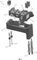
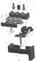
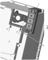
- the fuse module 10 includes a battery clamp 12, a fuse assembly 14, and a mounting cradle 16 that are coupled together in a vertically stacked arrangement as further described below.
- the battery clamp 12 may be formed of metal or any other suitably rigid, electrically conductive material and may include a ferrule portion 18 (best shown in Fig. 2 ) for removably fastening the battery clamp 12 to a positive terminal of an automobile battery.
- the battery clamp 12 may further include a substantially planar, T-shaped terminal portion 20 that extends generally horizontally from the front of the ferrule portion 18.
- the terminal portion 20 and the ferrule portion 18 of the battery clamp 12 may be formed from a single piece of material (e.g., stamped from a single sheet of metal) or may be formed from separate pieces of material that are welded, clinched, or otherwise joined together in a manner that provides robust electrical communication therebetween. It is contemplated that a ledge, block, or other support structure may be formed on, or affixed to, an underside of the terminal portion 20 to support the battery clamp 12 against the weight of the cantilevered fuse assembly 14 and mounting cradle 16 to reduce mechanical stress on the connection between the ferrule portion 18 and a battery terminal.
- the fuse assembly 14 includes an elongate mounting block 22 formed of an electrically insulting material (e.g., ceramic, plastic, polymer, etc.).
- the fuse assembly 14 includes a substantially planar bus bar 24 formed of an electrically conductive material (e.g., copper) that extends along a bottom surface of the mounting block 22.
- the bus bar 24 may sit atop the terminal portion 20 of the battery clamp 12 in electrical communication therewith.
- the fuse assembly 14 includes a plurality of fuses 26 1 , 26 2 , 26 3 that include respective fuse terminals 28 1 , 28 2 , 28 3 disposed on a top surface of the mounting block 22 and connected to the bus bar 24 by respective fusible elements 30 1 , 30 2 , 30 3 disposed on a vertical face of the mounting block 22.
- the bus bar 24 and the fuses 26 1 , 26 2 , 26 3 may be formed from a single piece of conductive material (e.g., stamped from a single sheet of copper) and may be bent or wrapped about the faces of the mounting block 22.
- the bus bar 24 and the fuses 26 1 , 26 2 , 26 3 may be formed of 1-millimeter-thick copper sheet, and each of the fuses 26 1 , 26 2 , 26 3 may have a rating of 80 amps. It will be appreciated that the bus bar 24 and the fuses 26 1 , 26 2 , 26 3 are not limited in this regard, and that the bus bar 24 and the fuses 26 1 , 26 2 , 26 3 may be formed of various other conductive materials and/or with different thicknesses to achieve different current ratings.
- the fuse assembly 14 may further include bus extensions 30, 32 extending from opposing ends of the bus bar 24.
- Each bus extension 30, 32 may be formed of a segment of sheet metal (e.g., copper sheet) that is bent into a generally L-shape to define respective, horizontally-oriented base portions 34, 36 and respective, vertically-oriented extension terminal portions 38, 40 that extend upwardly alongside the longitudinal end faces of the mounting block 22.
- the base portions 34, 36 may be clinched, welded, or otherwise joined to the bus bar 24 in a manner that provides robust electrical communication therebetween.
- the bus extensions 30, 32 may be formed of 0.8-millimeter-thick copper sheet (i.e., copper sheet that is thinner than the 1-millimeter-thick bus bar 24 described above) to facilitate connection to fuses having lower amperage ratings (e.g., 5-40 amps) than the fuses 26 1 , 26 2 , 26 3 described above.
- lower amperage fuses via the bus extensions 30, 32 will be described in greater detail below.
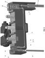
- the fuse assembly 14 includes electrically conductive terminal posts 42, 44 having respective polygonal flanges 46, 48 extending from their lower ends.
- the flanges 46, 48 may be seated within respective polygonal bores 50, 52 formed in the top of the mounting block 22 below the fuse terminals 28 1 , 28 3 of the outermost fuses 26 1 , 26 3 , with the terminal posts 42, 44 extending upwardly through respective apertures 54, 56 formed in the fuse terminals 28 1 , 28 3 (as shown in FIG. 1 ).
- the bores 50, 52 may be of similar size and shape to the flanges 46, 48 and may be configured to matingly receive the flanges 46, 48 in a close-clearance relationship therewith.
- the flanges 46, 48 may thereby restrict rotation of the terminal posts 42, 44 about their respective vertical axes.
- the terminal posts 42, 44 may be threaded for allowing ring terminals of conductors (not shown) to be placed over the terminal posts 42, 44 and secured against the fuse terminals 28 1 , 28 3 with nuts (not shown) that may be tightened onto the terminal posts 42, 44.
- various electrical systems or components of an automobile may be electrically coupled to a positive terminal of the automobile's battery via the terminal posts 42, 44, the fuse terminals 28 1 , 28 3 , the fusible elements 30 1 , 30 3 , the bus bar 24, and the battery clamp 12, with the fuses 26 1 , 26 3 providing over-current protection between the automobile battery and such electrical systems or components.
- the mounting cradle 16 may be a generally rectangular, cup-shaped member formed of an electrically insulating material (e.g., plastic, polymer, etc.).
- the mounting cradle 16 may hold the terminal portion 20 of the battery clamp 12 and the bottom of the fuse assembly 14, substantially covering the front and sides of the fuse assembly 14, with the terminal portion 20 extending through a recess 57 in the rear of the mounting cradle 16.
- a threaded mounting post 60 may be rigidly attached to, and may extend vertically from, a floor 62 of the mounting cradle 16.
- a flange 59 extending from a lower end of the mounting post 60 may be overmolded within the floor 62 of the mounting cradle 16.
- the mounting post 60 may extend upwardly through an aperture 61 in the terminal portion 20 of the battery clamp 12, through an aperture 63 in the bus bar 24, through a bore 64 formed in the mounting block 22, and through an aperture 65 in the fuse terminal 28 2 of the fuse 26 2 ( see also FIG. 3 ).
- a ring terminal of a conductor (not shown) may be placed over the mounting post 60 and secured against the fuse terminal 28 2 with a nut (not shown) that may be tightened onto the mounting post 60.
- tightening a nut onto the mounting post 60 may secure the mounting cradle 16, the battery clamp 12, and the fuse assembly 14 together in a vertically stacked arrangement.
- the mounting post 60 may be electrically insulated from the bus bar 24, such as by physical separation and/or electrically insulating material disposed therebetween, to prevent electrical current from bypassing the fusible element 30 2 and flowing from the bus bar 24 to the fuse terminal 28 2 via the mounting post 60.
- a tubular sleeve 66 may be disposed within the bore 64 in the mounting block 22 and may surround the mounting post 60 vertically intermediate the bus bar 24 and the fuse terminal 28 2 , with a bottom of the sleeve 66 engaging or proximate a top of the bus bar 24 and with a top of the sleeve 66 engaging or proximate a bottom of the fuse terminal 28 2 .
- the sleeve 66 may be formed of metal to provide an electrically-conductive pathway (i.e., a shunt) extending directly between the bus bar 24 and the fuse terminal 28 2 .
- the sleeve 66 may be formed of a non-conductive material (e.g., ceramic, plastic, etc.), whereby the only electrically-conductive path between the bus bar 24 and the fuse terminal 28 2 is through the fusible element 30 2 .
- the fuse assembly 14 may further include a cover 70 that may be affixed to a front of the mounting block 22, such as with mechanical fasteners or structures, adhesives, welding, etc.
- the cover 70 may be disposed over the fusible elements 30 1 , 30 2 , 30 3 for protecting the fusible elements 30 1 , 30 2 , 30 3 from ambient particulate as well as for containing electrical arcing in the fusible elements 30 1 , 30 2 , 30 3 that may result from blowing during an overcurrent condition.
- the bus extensions 30, 32 may facilitate the connection of fuses having low-medium amperage ratings (e.g., 5-40 amps) to the fuse assembly 14.
- the terminal portion 38 of the bus extension 30 may have forked terminals 76, 78 (best shown in FIG. 2 ) for receiving legs of respective blade fuses 80, 82.
- the blade fuses 80, 82 may be seated within respective recesses formed in the mounting cradle 16 and mounting block 22 and may be connected to respective electrical conductors 84, 86 ( see also FIG. 1 ) that extend through apertures in the bottom of the mounting cradle 16.
- the top edge of the terminal portion 40 of the bus extension 32 may facilitate connection to slotted cartridge fuses 88, 90 which may be seated within respective recesses formed in the mounting cradle 16 and mounting block 22 and may be and connected to respective electrical conductors 92, 94 ( see also FIG. 1 ) that extend through apertures in the bottom of the mounting cradle 16.
- the reduced thickness of the bus extension 32 relative to the bus bar 24 allows a conventional slotted cartridge fuse adapted for connection to a 0.8 millimeter terminal to be connected to the fuse assembly 14, for example.
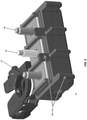
- the mounting cradle 16 of the fuse module 10 may be provided with numerous features for accommodating various application environments.
- FIG. 5 which depicts an embodiment of the fuse module 10 with the bus extensions 30, 32 and accompanying structures/features omitted
- the mounting cradle 16 may be provided with ridges 100, castellations 102, and/or other surface features for routing flexible conductors (not shown) to the terminals posts 42, 44 and to the mounting post 60 in a desired manner.
- the mounting cradle 16 may be provided with a stabilizing arm 104 extending therefrom, the stabilizing arm 104 having detents 106, 108 adapted to fit within keyhole-shaped recesses 110, 112 in a battery case 115 for preventing rotation of the fuse module 10 and for providing the fuse module 10 with mechanical strain relief.
- the fuse module 10 of the present disclosure provides numerous advantages relative to pre-fuse boxes that are currently available on the market. For example, owing to the configuration of the above-described mounting cradle 16, with the mounting post 60 extending through, and integral with, the fuse assembly 14, the entire fuse module 10 can be mounted directly to a positive terminal of an automobile battery in close proximity thereto without any flexible conductors extending therebetween. This provides a significant space and material savings relative to conventional pre-fuse boxes. Additionally, the bus extensions 30, 32, which are mechanically joined directly to the bus bar 24, facilitate the provision of terminals with proper mechanical and material characteristics for accommodating low-medium-current fuses in compact configuration.
Landscapes
- Engineering & Computer Science (AREA)
- Power Engineering (AREA)
- Chemical & Material Sciences (AREA)
- Chemical Kinetics & Catalysis (AREA)
- Electrochemistry (AREA)
- General Chemical & Material Sciences (AREA)
- Fuses (AREA)
- Connection Of Batteries Or Terminals (AREA)
Claims (9)
- Sicherungsmodul (10), das Folgendes umfasst:eine elektrisch leitende Batterieklemme (12), die zur Verbindung mit einem Batterieanschluss geeignet ist;eine Sicherungsanordnung (14), die Folgendes umfasst:einen Montageblock (22), der aus einem elektrisch isolierenden Material gebildet ist;eine elektrisch leitende Sammelschiene (24), die auf einer ersten Seite des Montageblocks (22) in Kontakt mit der Batterieklemme (12) angeordnet ist;gekennzeichnet durch:eine Vielzahl von Sicherungsanschlüssen (281, 282, 283), die auf einer der ersten Seite gegenüber liegenden zweiten Seite des Montageblocks (22) angeordnet sind und durch jeweilige Schmelzelemente (301, 302, 303) mit der Sammelschiene (24) verbunden sind; undeinen elektrisch leitenden Anschlussstab (42, 44), der sich durch einen der Sicherungsanschlüsse (281, 282, 283) erstreckt, um die Verbindung mit einer ersten elektrischen Komponente zu erleichtern; undeine Montagehalterung (16), die die Sicherungsanordnung (14) und mindestens einen Abschnitt der Batterieklemme (12) hält, wobei die Montagehalterung (16) einen Montagestab (60) umfasst, der sich durch die Batterieklemme (12), die Sammelschiene (24), den Montageblock (22) und einen der Sicherungsanschlüsse (281, 282, 283) erstreckt, zum Erleichtern der Verbindung mit einer zweiten elektrischen Komponente und zum Befestigen der Batterieklemme (12), der Sicherungsanordnung (14) und der Montagehalterung (16) aneinander in einer gestapelten Anordnung, wobei der Montagestab (60) von einer rohrförmigen Hülse (66) umgeben ist, die sich zwischen der Sammelschiene (24) und dem Sicherungsanschluss (281, 282, 283) erstreckt, durch den sich der Montagestab (60) erstreckt.
- Sicherungsmodul (10) nach Anspruch 1, wobei die rohrförmige Hülse (66) aus einem elektrisch leitenden Material gebildet ist und einen elektrisch leitenden Pfad zwischen der Sammelschiene (24) und dem Sicherungsanschluss (281, 282, 283) bereitstellt, durch den sich der Montagestab (60) erstreckt.
- Sicherungsmodul (10) nach Anspruch 1, wobei die rohrförmige Hülse (66) aus einem elektrisch isolierenden Material gebildet ist.
- Sicherungsmodul (10) nach Anspruch 1, das ferner eine elektrisch leitende Busverlängerung (30, 32) umfasst, die sich von der Sammelschiene (24) erstreckt, um die Verbindung mit einer Sicherung zu erleichtern.
- Sicherungsmodul (10) nach Anspruch 4, wobei die Busverlängerung (30, 32) gegabelt ist, um eine Flachsicherung (80, 82) aufzunehmen.
- Sicherungsmodul (10) nach Anspruch 4, wobei die Busverlängerung (30, 32) eine flache Kante definiert, die angepasst ist, um eine geschlitzte Sicherung aufzunehmen.
- Sicherungsmodul (10) nach Anspruch 4, wobei sich die Busverlängerung (30, 32) von der Sammelschiene (24) in Bezug auf Material und/oder Dicke unterscheidet, so dass die Busverlängerung (30, 32) eine niedrigere Strombelastbarkeit als die Sammelschiene (24) aufweist.
- Sicherungsmodul (10) nach Anspruch 1, wobei mindestens einer von dem Montageblock (22) und der Montagehalterung (16) eine Aussparung zum Halten einer Sicherung definiert.
- Sicherungsmodul (10) nach Anspruch 1, wobei die elektrisch leitende Batterieklemme (12) einen Hülsenabschnitt (18) zum Verbinden mit dem Batterieanschluss umfasst und ferner einen Anschlussabschnitt umfasst, der sich von dem Hülsenabschnitt (18) erstreckt.
Applications Claiming Priority (2)
| Application Number | Priority Date | Filing Date | Title |
|---|---|---|---|
| US201662430168P | 2016-12-05 | 2016-12-05 | |
| PCT/US2017/064747 WO2018106715A1 (en) | 2016-12-05 | 2017-12-05 | Battery terminal fuse module |
Publications (3)
| Publication Number | Publication Date |
|---|---|
| EP3552221A1 EP3552221A1 (de) | 2019-10-16 |
| EP3552221A4 EP3552221A4 (de) | 2020-06-03 |
| EP3552221B1 true EP3552221B1 (de) | 2022-03-16 |
Family
ID=62491317
Family Applications (1)
| Application Number | Title | Priority Date | Filing Date |
|---|---|---|---|
| EP17878360.1A Active EP3552221B1 (de) | 2016-12-05 | 2017-12-05 | Sicherungsmodul für batterieklemme |
Country Status (4)
| Country | Link |
|---|---|
| US (2) | US10148044B2 (de) |
| EP (1) | EP3552221B1 (de) |
| JP (1) | JP7033595B2 (de) |
| WO (1) | WO2018106715A1 (de) |
Families Citing this family (6)
| Publication number | Priority date | Publication date | Assignee | Title |
|---|---|---|---|---|
| US11037750B2 (en) * | 2018-09-13 | 2021-06-15 | Yazaki North America, Inc. | High current fuse block |
| KR102634405B1 (ko) * | 2018-12-10 | 2024-02-06 | 현대자동차주식회사 | 퓨즈 통합형 정션 커넥터 조립체 |
| US11355300B2 (en) * | 2019-05-07 | 2022-06-07 | Littelfuse, Inc. | Active/passive automotive fuse module |
| US12020882B2 (en) * | 2021-08-06 | 2024-06-25 | Littelfuse, Inc. | Fuse assembly including anti-rotation device |
| US12387898B2 (en) * | 2023-12-08 | 2025-08-12 | Littelfuse, Inc. | Jump stud fuse module |
| EP4654241A1 (de) * | 2024-05-21 | 2025-11-26 | Aptiv Technologies AG | Sicherungshalter für hochpowert-stromkreise |
Family Cites Families (17)
| Publication number | Priority date | Publication date | Assignee | Title |
|---|---|---|---|---|
| US5643693A (en) * | 1995-10-30 | 1997-07-01 | Yazaki Corporation | Battery-mounted power distribution module |
| US6642633B1 (en) * | 2001-06-27 | 2003-11-04 | Yazaki North America, Inc. | Power management assembly |
| US6902434B2 (en) * | 2002-07-23 | 2005-06-07 | Cooper Technologies Company | Battery fuse bus bar assembly |
| US6855008B1 (en) * | 2003-10-06 | 2005-02-15 | Royal Die & Stamping Co., Inc. | Fuse holder with adjustable terminals |
| JP4181028B2 (ja) * | 2003-12-22 | 2008-11-12 | 矢崎総業株式会社 | 電気接続箱 |
| US7990738B2 (en) * | 2008-04-02 | 2011-08-02 | Littelfuse, Inc. | Master fuse module |
| WO2009140277A1 (en) * | 2008-05-15 | 2009-11-19 | Johnson Controls - Saft Advanced Power Solutions Llc | Battery system |
| JP5189920B2 (ja) * | 2008-07-25 | 2013-04-24 | 矢崎総業株式会社 | ヒュージブルリンクユニット |
| US8056305B1 (en) * | 2008-09-30 | 2011-11-15 | Bank Of America Corporation | Automatic strapping and bagging of funds |
| JP5328459B2 (ja) * | 2009-04-10 | 2013-10-30 | 矢崎総業株式会社 | ヒューズユニット |
| US8269596B2 (en) * | 2009-12-23 | 2012-09-18 | Cooper Technologies Company | Universal dual stud modular fuse holder assembly for bussed and non-bussed power connections |
| US8665056B2 (en) | 2010-05-18 | 2014-03-04 | Littlefuse, Inc. | Fuse assembly |
| US20150325934A1 (en) * | 2014-02-14 | 2015-11-12 | Royal Die & Stamping Co., Inc. | One-piece fusible battery terminal clamp |
| US9093768B1 (en) * | 2014-02-14 | 2015-07-28 | Royal Die & Stamping Co., Inc. | One-piece fusible battery terminal clamp |
| JP6014084B2 (ja) * | 2014-07-16 | 2016-10-25 | 矢崎総業株式会社 | ヒューズユニットの製造方法、型構造を用いた成形方法およびヒューズユニット |
| JP6430834B2 (ja) * | 2015-01-14 | 2018-11-28 | 矢崎総業株式会社 | ヒューズユニット、及び、ヒューズユニット組み付け方法 |
| US9728363B2 (en) * | 2015-11-25 | 2017-08-08 | Sumitomo Wiring Systems, Ltd. | Pre-fuse assembly with horizontal jump post |
-
2017
- 2017-12-05 JP JP2019530192A patent/JP7033595B2/ja active Active
- 2017-12-05 EP EP17878360.1A patent/EP3552221B1/de active Active
- 2017-12-05 US US15/832,477 patent/US10148044B2/en active Active
- 2017-12-05 WO PCT/US2017/064747 patent/WO2018106715A1/en not_active Ceased
-
2018
- 2018-10-19 US US16/165,684 patent/US10446989B2/en active Active
Also Published As
| Publication number | Publication date |
|---|---|
| EP3552221A1 (de) | 2019-10-16 |
| JP2020514952A (ja) | 2020-05-21 |
| US20190058294A1 (en) | 2019-02-21 |
| EP3552221A4 (de) | 2020-06-03 |
| WO2018106715A1 (en) | 2018-06-14 |
| JP7033595B2 (ja) | 2022-03-10 |
| US10148044B2 (en) | 2018-12-04 |
| US10446989B2 (en) | 2019-10-15 |
| US20180205188A1 (en) | 2018-07-19 |
Similar Documents
| Publication | Publication Date | Title |
|---|---|---|
| EP3552221B1 (de) | Sicherungsmodul für batterieklemme | |
| US11282667B2 (en) | Low profile integrated fuse module | |
| JP6581958B2 (ja) | 電圧検出構造および電圧検出モジュール | |
| US11043721B2 (en) | Connection structure of conductor and conductive module | |
| KR20150106915A (ko) | 배터리 분배 유닛 | |
| JP2018097986A (ja) | 導体ユニットの固定構造 | |
| US11189450B2 (en) | Low profile integrated fuse module | |
| CN108701800A (zh) | 布线模块 | |
| US11062870B2 (en) | Integrated fuse module | |
| EP4104197B1 (de) | Integriertes sicherungsmodul mit flachem profil | |
| JP2015220769A (ja) | 接続導体ユニット | |
| US11081814B2 (en) | Wiring module | |
| CN110854770A (zh) | 供电端子结构、电气连接箱以及线束 | |
| EP4567855A1 (de) | Sicherungsmodul für sprungbolzen | |
| WO2009029061A1 (en) | Battery terminal connector bar with integral circuit protection |
Legal Events
| Date | Code | Title | Description |
|---|---|---|---|
| STAA | Information on the status of an ep patent application or granted ep patent |
Free format text: STATUS: THE INTERNATIONAL PUBLICATION HAS BEEN MADE |
|
| PUAI | Public reference made under article 153(3) epc to a published international application that has entered the european phase |
Free format text: ORIGINAL CODE: 0009012 |
|
| STAA | Information on the status of an ep patent application or granted ep patent |
Free format text: STATUS: REQUEST FOR EXAMINATION WAS MADE |
|
| 17P | Request for examination filed |
Effective date: 20190705 |
|
| AK | Designated contracting states |
Kind code of ref document: A1 Designated state(s): AL AT BE BG CH CY CZ DE DK EE ES FI FR GB GR HR HU IE IS IT LI LT LU LV MC MK MT NL NO PL PT RO RS SE SI SK SM TR |
|
| AX | Request for extension of the european patent |
Extension state: BA ME |
|
| DAV | Request for validation of the european patent (deleted) | ||
| DAX | Request for extension of the european patent (deleted) | ||
| A4 | Supplementary search report drawn up and despatched |
Effective date: 20200508 |
|
| RIC1 | Information provided on ipc code assigned before grant |
Ipc: H01H 85/20 20060101AFI20200501BHEP |
|
| GRAP | Despatch of communication of intention to grant a patent |
Free format text: ORIGINAL CODE: EPIDOSNIGR1 |
|
| STAA | Information on the status of an ep patent application or granted ep patent |
Free format text: STATUS: GRANT OF PATENT IS INTENDED |
|
| INTG | Intention to grant announced |
Effective date: 20210901 |
|
| GRAJ | Information related to disapproval of communication of intention to grant by the applicant or resumption of examination proceedings by the epo deleted |
Free format text: ORIGINAL CODE: EPIDOSDIGR1 |
|
| STAA | Information on the status of an ep patent application or granted ep patent |
Free format text: STATUS: REQUEST FOR EXAMINATION WAS MADE |
|
| GRAS | Grant fee paid |
Free format text: ORIGINAL CODE: EPIDOSNIGR3 |
|
| STAA | Information on the status of an ep patent application or granted ep patent |
Free format text: STATUS: GRANT OF PATENT IS INTENDED |
|
| GRAP | Despatch of communication of intention to grant a patent |
Free format text: ORIGINAL CODE: EPIDOSNIGR1 |
|
| GRAA | (expected) grant |
Free format text: ORIGINAL CODE: 0009210 |
|
| STAA | Information on the status of an ep patent application or granted ep patent |
Free format text: STATUS: THE PATENT HAS BEEN GRANTED |
|
| INTC | Intention to grant announced (deleted) | ||
| INTG | Intention to grant announced |
Effective date: 20220125 |
|
| AK | Designated contracting states |
Kind code of ref document: B1 Designated state(s): AL AT BE BG CH CY CZ DE DK EE ES FI FR GB GR HR HU IE IS IT LI LT LU LV MC MK MT NL NO PL PT RO RS SE SI SK SM TR |
|
| REG | Reference to a national code |
Ref country code: GB Ref legal event code: FG4D |
|
| REG | Reference to a national code |
Ref country code: CH Ref legal event code: EP Ref country code: DE Ref legal event code: R096 Ref document number: 602017054797 Country of ref document: DE |
|
| REG | Reference to a national code |
Ref country code: IE Ref legal event code: FG4D |
|
| REG | Reference to a national code |
Ref country code: AT Ref legal event code: REF Ref document number: 1476491 Country of ref document: AT Kind code of ref document: T Effective date: 20220415 |
|
| REG | Reference to a national code |
Ref country code: LT Ref legal event code: MG9D |
|
| REG | Reference to a national code |
Ref country code: NL Ref legal event code: MP Effective date: 20220316 |
|
| PG25 | Lapsed in a contracting state [announced via postgrant information from national office to epo] |
Ref country code: SE Free format text: LAPSE BECAUSE OF FAILURE TO SUBMIT A TRANSLATION OF THE DESCRIPTION OR TO PAY THE FEE WITHIN THE PRESCRIBED TIME-LIMIT Effective date: 20220316 Ref country code: RS Free format text: LAPSE BECAUSE OF FAILURE TO SUBMIT A TRANSLATION OF THE DESCRIPTION OR TO PAY THE FEE WITHIN THE PRESCRIBED TIME-LIMIT Effective date: 20220316 Ref country code: NO Free format text: LAPSE BECAUSE OF FAILURE TO SUBMIT A TRANSLATION OF THE DESCRIPTION OR TO PAY THE FEE WITHIN THE PRESCRIBED TIME-LIMIT Effective date: 20220616 Ref country code: LT Free format text: LAPSE BECAUSE OF FAILURE TO SUBMIT A TRANSLATION OF THE DESCRIPTION OR TO PAY THE FEE WITHIN THE PRESCRIBED TIME-LIMIT Effective date: 20220316 Ref country code: HR Free format text: LAPSE BECAUSE OF FAILURE TO SUBMIT A TRANSLATION OF THE DESCRIPTION OR TO PAY THE FEE WITHIN THE PRESCRIBED TIME-LIMIT Effective date: 20220316 Ref country code: BG Free format text: LAPSE BECAUSE OF FAILURE TO SUBMIT A TRANSLATION OF THE DESCRIPTION OR TO PAY THE FEE WITHIN THE PRESCRIBED TIME-LIMIT Effective date: 20220616 |
|
| REG | Reference to a national code |
Ref country code: AT Ref legal event code: MK05 Ref document number: 1476491 Country of ref document: AT Kind code of ref document: T Effective date: 20220316 |
|
| PG25 | Lapsed in a contracting state [announced via postgrant information from national office to epo] |
Ref country code: LV Free format text: LAPSE BECAUSE OF FAILURE TO SUBMIT A TRANSLATION OF THE DESCRIPTION OR TO PAY THE FEE WITHIN THE PRESCRIBED TIME-LIMIT Effective date: 20220316 Ref country code: GR Free format text: LAPSE BECAUSE OF FAILURE TO SUBMIT A TRANSLATION OF THE DESCRIPTION OR TO PAY THE FEE WITHIN THE PRESCRIBED TIME-LIMIT Effective date: 20220617 Ref country code: FI Free format text: LAPSE BECAUSE OF FAILURE TO SUBMIT A TRANSLATION OF THE DESCRIPTION OR TO PAY THE FEE WITHIN THE PRESCRIBED TIME-LIMIT Effective date: 20220316 |
|
| PG25 | Lapsed in a contracting state [announced via postgrant information from national office to epo] |
Ref country code: NL Free format text: LAPSE BECAUSE OF FAILURE TO SUBMIT A TRANSLATION OF THE DESCRIPTION OR TO PAY THE FEE WITHIN THE PRESCRIBED TIME-LIMIT Effective date: 20220316 |
|
| PG25 | Lapsed in a contracting state [announced via postgrant information from national office to epo] |
Ref country code: SM Free format text: LAPSE BECAUSE OF FAILURE TO SUBMIT A TRANSLATION OF THE DESCRIPTION OR TO PAY THE FEE WITHIN THE PRESCRIBED TIME-LIMIT Effective date: 20220316 Ref country code: SK Free format text: LAPSE BECAUSE OF FAILURE TO SUBMIT A TRANSLATION OF THE DESCRIPTION OR TO PAY THE FEE WITHIN THE PRESCRIBED TIME-LIMIT Effective date: 20220316 Ref country code: RO Free format text: LAPSE BECAUSE OF FAILURE TO SUBMIT A TRANSLATION OF THE DESCRIPTION OR TO PAY THE FEE WITHIN THE PRESCRIBED TIME-LIMIT Effective date: 20220316 Ref country code: PT Free format text: LAPSE BECAUSE OF FAILURE TO SUBMIT A TRANSLATION OF THE DESCRIPTION OR TO PAY THE FEE WITHIN THE PRESCRIBED TIME-LIMIT Effective date: 20220718 Ref country code: ES Free format text: LAPSE BECAUSE OF FAILURE TO SUBMIT A TRANSLATION OF THE DESCRIPTION OR TO PAY THE FEE WITHIN THE PRESCRIBED TIME-LIMIT Effective date: 20220316 Ref country code: EE Free format text: LAPSE BECAUSE OF FAILURE TO SUBMIT A TRANSLATION OF THE DESCRIPTION OR TO PAY THE FEE WITHIN THE PRESCRIBED TIME-LIMIT Effective date: 20220316 Ref country code: CZ Free format text: LAPSE BECAUSE OF FAILURE TO SUBMIT A TRANSLATION OF THE DESCRIPTION OR TO PAY THE FEE WITHIN THE PRESCRIBED TIME-LIMIT Effective date: 20220316 Ref country code: AT Free format text: LAPSE BECAUSE OF FAILURE TO SUBMIT A TRANSLATION OF THE DESCRIPTION OR TO PAY THE FEE WITHIN THE PRESCRIBED TIME-LIMIT Effective date: 20220316 |
|
| PG25 | Lapsed in a contracting state [announced via postgrant information from national office to epo] |
Ref country code: PL Free format text: LAPSE BECAUSE OF FAILURE TO SUBMIT A TRANSLATION OF THE DESCRIPTION OR TO PAY THE FEE WITHIN THE PRESCRIBED TIME-LIMIT Effective date: 20220316 Ref country code: IS Free format text: LAPSE BECAUSE OF FAILURE TO SUBMIT A TRANSLATION OF THE DESCRIPTION OR TO PAY THE FEE WITHIN THE PRESCRIBED TIME-LIMIT Effective date: 20220716 Ref country code: AL Free format text: LAPSE BECAUSE OF FAILURE TO SUBMIT A TRANSLATION OF THE DESCRIPTION OR TO PAY THE FEE WITHIN THE PRESCRIBED TIME-LIMIT Effective date: 20220316 |
|
| REG | Reference to a national code |
Ref country code: DE Ref legal event code: R097 Ref document number: 602017054797 Country of ref document: DE |
|
| PLBE | No opposition filed within time limit |
Free format text: ORIGINAL CODE: 0009261 |
|
| STAA | Information on the status of an ep patent application or granted ep patent |
Free format text: STATUS: NO OPPOSITION FILED WITHIN TIME LIMIT |
|
| PG25 | Lapsed in a contracting state [announced via postgrant information from national office to epo] |
Ref country code: DK Free format text: LAPSE BECAUSE OF FAILURE TO SUBMIT A TRANSLATION OF THE DESCRIPTION OR TO PAY THE FEE WITHIN THE PRESCRIBED TIME-LIMIT Effective date: 20220316 |
|
| 26N | No opposition filed |
Effective date: 20221219 |
|
| PG25 | Lapsed in a contracting state [announced via postgrant information from national office to epo] |
Ref country code: SI Free format text: LAPSE BECAUSE OF FAILURE TO SUBMIT A TRANSLATION OF THE DESCRIPTION OR TO PAY THE FEE WITHIN THE PRESCRIBED TIME-LIMIT Effective date: 20220316 |
|
| P01 | Opt-out of the competence of the unified patent court (upc) registered |
Effective date: 20230607 |
|
| REG | Reference to a national code |
Ref country code: CH Ref legal event code: PL |
|
| REG | Reference to a national code |
Ref country code: BE Ref legal event code: MM Effective date: 20221231 |
|
| PG25 | Lapsed in a contracting state [announced via postgrant information from national office to epo] |
Ref country code: LU Free format text: LAPSE BECAUSE OF NON-PAYMENT OF DUE FEES Effective date: 20221205 |
|
| PG25 | Lapsed in a contracting state [announced via postgrant information from national office to epo] |
Ref country code: LI Free format text: LAPSE BECAUSE OF NON-PAYMENT OF DUE FEES Effective date: 20221231 Ref country code: IE Free format text: LAPSE BECAUSE OF NON-PAYMENT OF DUE FEES Effective date: 20221205 Ref country code: CH Free format text: LAPSE BECAUSE OF NON-PAYMENT OF DUE FEES Effective date: 20221231 |
|
| PG25 | Lapsed in a contracting state [announced via postgrant information from national office to epo] |
Ref country code: BE Free format text: LAPSE BECAUSE OF NON-PAYMENT OF DUE FEES Effective date: 20221231 |
|
| PG25 | Lapsed in a contracting state [announced via postgrant information from national office to epo] |
Ref country code: HU Free format text: LAPSE BECAUSE OF FAILURE TO SUBMIT A TRANSLATION OF THE DESCRIPTION OR TO PAY THE FEE WITHIN THE PRESCRIBED TIME-LIMIT; INVALID AB INITIO Effective date: 20171205 |
|
| PG25 | Lapsed in a contracting state [announced via postgrant information from national office to epo] |
Ref country code: CY Free format text: LAPSE BECAUSE OF FAILURE TO SUBMIT A TRANSLATION OF THE DESCRIPTION OR TO PAY THE FEE WITHIN THE PRESCRIBED TIME-LIMIT Effective date: 20220316 |
|
| PG25 | Lapsed in a contracting state [announced via postgrant information from national office to epo] |
Ref country code: MK Free format text: LAPSE BECAUSE OF FAILURE TO SUBMIT A TRANSLATION OF THE DESCRIPTION OR TO PAY THE FEE WITHIN THE PRESCRIBED TIME-LIMIT Effective date: 20220316 |
|
| PG25 | Lapsed in a contracting state [announced via postgrant information from national office to epo] |
Ref country code: MC Free format text: LAPSE BECAUSE OF FAILURE TO SUBMIT A TRANSLATION OF THE DESCRIPTION OR TO PAY THE FEE WITHIN THE PRESCRIBED TIME-LIMIT Effective date: 20220316 |
|
| PG25 | Lapsed in a contracting state [announced via postgrant information from national office to epo] |
Ref country code: MC Free format text: LAPSE BECAUSE OF FAILURE TO SUBMIT A TRANSLATION OF THE DESCRIPTION OR TO PAY THE FEE WITHIN THE PRESCRIBED TIME-LIMIT Effective date: 20220316 |
|
| PG25 | Lapsed in a contracting state [announced via postgrant information from national office to epo] |
Ref country code: MT Free format text: LAPSE BECAUSE OF FAILURE TO SUBMIT A TRANSLATION OF THE DESCRIPTION OR TO PAY THE FEE WITHIN THE PRESCRIBED TIME-LIMIT Effective date: 20220316 |
|
| PGFP | Annual fee paid to national office [announced via postgrant information from national office to epo] |
Ref country code: FR Payment date: 20250930 Year of fee payment: 9 |
|
| PG25 | Lapsed in a contracting state [announced via postgrant information from national office to epo] |
Ref country code: TR Free format text: LAPSE BECAUSE OF FAILURE TO SUBMIT A TRANSLATION OF THE DESCRIPTION OR TO PAY THE FEE WITHIN THE PRESCRIBED TIME-LIMIT Effective date: 20220316 |
|
| PGFP | Annual fee paid to national office [announced via postgrant information from national office to epo] |
Ref country code: DE Payment date: 20250930 Year of fee payment: 9 |
|
| PGFP | Annual fee paid to national office [announced via postgrant information from national office to epo] |
Ref country code: GB Payment date: 20251001 Year of fee payment: 9 |
|
| PGFP | Annual fee paid to national office [announced via postgrant information from national office to epo] |
Ref country code: IT Payment date: 20251121 Year of fee payment: 9 |