EP3552221B1 - Battery terminal fuse module - Google Patents
Battery terminal fuse module Download PDFInfo
- Publication number
- EP3552221B1 EP3552221B1 EP17878360.1A EP17878360A EP3552221B1 EP 3552221 B1 EP3552221 B1 EP 3552221B1 EP 17878360 A EP17878360 A EP 17878360A EP 3552221 B1 EP3552221 B1 EP 3552221B1
- Authority
- EP
- European Patent Office
- Prior art keywords
- fuse
- mounting
- terminal
- bus bar
- module
- Prior art date
- Legal status (The legal status is an assumption and is not a legal conclusion. Google has not performed a legal analysis and makes no representation as to the accuracy of the status listed.)
- Active
Links
Images

Classifications
-
- H—ELECTRICITY
- H01—ELECTRIC ELEMENTS
- H01R—ELECTRICALLY-CONDUCTIVE CONNECTIONS; STRUCTURAL ASSOCIATIONS OF A PLURALITY OF MUTUALLY-INSULATED ELECTRICAL CONNECTING ELEMENTS; COUPLING DEVICES; CURRENT COLLECTORS
- H01R13/00—Details of coupling devices of the kinds covered by groups H01R12/70 or H01R24/00 - H01R33/00
- H01R13/66—Structural association with built-in electrical component
- H01R13/68—Structural association with built-in electrical component with built-in fuse
- H01R13/684—Structural association with built-in electrical component with built-in fuse the fuse being removable
-
- H—ELECTRICITY
- H01—ELECTRIC ELEMENTS
- H01H—ELECTRIC SWITCHES; RELAYS; SELECTORS; EMERGENCY PROTECTIVE DEVICES
- H01H85/00—Protective devices in which the current flows through a part of fusible material and this current is interrupted by displacement of the fusible material when this current becomes excessive
- H01H85/02—Details
- H01H85/0241—Structural association of a fuse and another component or apparatus
-
- H—ELECTRICITY
- H01—ELECTRIC ELEMENTS
- H01M—PROCESSES OR MEANS, e.g. BATTERIES, FOR THE DIRECT CONVERSION OF CHEMICAL ENERGY INTO ELECTRICAL ENERGY
- H01M50/00—Constructional details or processes of manufacture of the non-active parts of electrochemical cells other than fuel cells, e.g. hybrid cells
- H01M50/50—Current conducting connections for cells or batteries
- H01M50/572—Means for preventing undesired use or discharge
- H01M50/574—Devices or arrangements for the interruption of current
- H01M50/583—Devices or arrangements for the interruption of current in response to current, e.g. fuses
-
- H—ELECTRICITY
- H01—ELECTRIC ELEMENTS
- H01H—ELECTRIC SWITCHES; RELAYS; SELECTORS; EMERGENCY PROTECTIVE DEVICES
- H01H85/00—Protective devices in which the current flows through a part of fusible material and this current is interrupted by displacement of the fusible material when this current becomes excessive
- H01H85/02—Details
- H01H85/0241—Structural association of a fuse and another component or apparatus
- H01H2085/025—Structural association with a binding post of a storage battery
-
- H—ELECTRICITY
- H01—ELECTRIC ELEMENTS
- H01H—ELECTRIC SWITCHES; RELAYS; SELECTORS; EMERGENCY PROTECTIVE DEVICES
- H01H85/00—Protective devices in which the current flows through a part of fusible material and this current is interrupted by displacement of the fusible material when this current becomes excessive
- H01H85/02—Details
- H01H85/04—Fuses, i.e. expendable parts of the protective device, e.g. cartridges
- H01H85/05—Component parts thereof
- H01H85/055—Fusible members
- H01H2085/0555—Input terminal connected to a plurality of output terminals, e.g. multielectrode
-
- H—ELECTRICITY
- H01—ELECTRIC ELEMENTS
- H01H—ELECTRIC SWITCHES; RELAYS; SELECTORS; EMERGENCY PROTECTIVE DEVICES
- H01H2231/00—Applications
- H01H2231/024—Dispensing machine
-
- H—ELECTRICITY
- H01—ELECTRIC ELEMENTS
- H01H—ELECTRIC SWITCHES; RELAYS; SELECTORS; EMERGENCY PROTECTIVE DEVICES
- H01H85/00—Protective devices in which the current flows through a part of fusible material and this current is interrupted by displacement of the fusible material when this current becomes excessive
- H01H85/02—Details
- H01H85/04—Fuses, i.e. expendable parts of the protective device, e.g. cartridges
- H01H85/05—Component parts thereof
- H01H85/165—Casings
-
- H—ELECTRICITY
- H01—ELECTRIC ELEMENTS
- H01H—ELECTRIC SWITCHES; RELAYS; SELECTORS; EMERGENCY PROTECTIVE DEVICES
- H01H85/00—Protective devices in which the current flows through a part of fusible material and this current is interrupted by displacement of the fusible material when this current becomes excessive
- H01H85/02—Details
- H01H85/20—Bases for supporting the fuse; Separate parts thereof
- H01H85/203—Bases for supporting the fuse; Separate parts thereof for fuses with blade type terminals
- H01H85/2035—Bases for supporting the fuse; Separate parts thereof for fuses with blade type terminals for miniature fuses with parallel side contacts
-
- H—ELECTRICITY
- H01—ELECTRIC ELEMENTS
- H01R—ELECTRICALLY-CONDUCTIVE CONNECTIONS; STRUCTURAL ASSOCIATIONS OF A PLURALITY OF MUTUALLY-INSULATED ELECTRICAL CONNECTING ELEMENTS; COUPLING DEVICES; CURRENT COLLECTORS
- H01R2201/00—Connectors or connections adapted for particular applications
- H01R2201/26—Connectors or connections adapted for particular applications for vehicles
-
- Y—GENERAL TAGGING OF NEW TECHNOLOGICAL DEVELOPMENTS; GENERAL TAGGING OF CROSS-SECTIONAL TECHNOLOGIES SPANNING OVER SEVERAL SECTIONS OF THE IPC; TECHNICAL SUBJECTS COVERED BY FORMER USPC CROSS-REFERENCE ART COLLECTIONS [XRACs] AND DIGESTS
- Y02—TECHNOLOGIES OR APPLICATIONS FOR MITIGATION OR ADAPTATION AGAINST CLIMATE CHANGE
- Y02E—REDUCTION OF GREENHOUSE GAS [GHG] EMISSIONS, RELATED TO ENERGY GENERATION, TRANSMISSION OR DISTRIBUTION
- Y02E60/00—Enabling technologies; Technologies with a potential or indirect contribution to GHG emissions mitigation
- Y02E60/10—Energy storage using batteries
Definitions
- the disclosure relates generally to the field of circuit protection devices, and relates more particularly to a battery terminal fuse module suitable for automotive battery applications.
- pre-fuse boxes disposed within automobile engine compartments and connected to automobile battery terminals.
- the main purpose of a pre-fuse box in an automobile is to prevent electrical damage that may result from short-circuiting in high-current-conducting wires that may occur in the event of an accident.
- US5643693 discloses in accordance with its abstract: 'An electrical power distribution module for use with an automotive vehicle electrical system is adapted to be mounted on the top surface of a standard automotive lead-acid storage battery and connect with a battery terminal extending therefrom.
- the power distribution module includes a battery post connecting assembly for housing a terminal connector for making electrical connections with the battery terminal and alternator and starter cables, a fuse block for receiving a plurality of fuses associated with separate vehicle electrical circuits, and a harness guide channel for routing a plurality of wires which connect the fuses with their associated circuits.
- the power distribution module is mounted to lay flat on top of the battery's upper surface with the battery terminal extending upwardly into the module to be engaged by the battery terminal connector.
- the module does not extend substantially above the highest point of the battery terminal, nor does it extend laterally substantially outside of the battery perimeter.
- a cover is attached to the power distribution module and has hinged sections which may be opened to provide access to the battery terminal connector and the fuse receptacles.
- a fuse module in accordance with the invention is described in claim 1.
- the fuse module 10 may be coupled directly to a positive terminal of an automobile battery with no flexible electrical conductors extending therebetween, and may facilitate connection to a plurality of low and medium-current fuses for protecting a variety of electrical loads (e.g., an air conditioning unit, a stereo, etc.) that are powered by the automobile battery.
- the fuse module 10 includes an integrated mounting structure that allows the fuse module 10 to be implemented in a compact, space-saving form factor relative to pre-fuse boxes that are currently available on the market.
- the fuse module 10 includes a battery clamp 12, a fuse assembly 14, and a mounting cradle 16 that are coupled together in a vertically stacked arrangement as further described below.
- the battery clamp 12 may be formed of metal or any other suitably rigid, electrically conductive material and may include a ferrule portion 18 (best shown in Fig. 2 ) for removably fastening the battery clamp 12 to a positive terminal of an automobile battery.
- the battery clamp 12 may further include a substantially planar, T-shaped terminal portion 20 that extends generally horizontally from the front of the ferrule portion 18.
- the terminal portion 20 and the ferrule portion 18 of the battery clamp 12 may be formed from a single piece of material (e.g., stamped from a single sheet of metal) or may be formed from separate pieces of material that are welded, clinched, or otherwise joined together in a manner that provides robust electrical communication therebetween. It is contemplated that a ledge, block, or other support structure may be formed on, or affixed to, an underside of the terminal portion 20 to support the battery clamp 12 against the weight of the cantilevered fuse assembly 14 and mounting cradle 16 to reduce mechanical stress on the connection between the ferrule portion 18 and a battery terminal.
- the fuse assembly 14 includes an elongate mounting block 22 formed of an electrically insulting material (e.g., ceramic, plastic, polymer, etc.).
- the fuse assembly 14 includes a substantially planar bus bar 24 formed of an electrically conductive material (e.g., copper) that extends along a bottom surface of the mounting block 22.
- the bus bar 24 may sit atop the terminal portion 20 of the battery clamp 12 in electrical communication therewith.
- the fuse assembly 14 includes a plurality of fuses 26 1 , 26 2 , 26 3 that include respective fuse terminals 28 1 , 28 2 , 28 3 disposed on a top surface of the mounting block 22 and connected to the bus bar 24 by respective fusible elements 30 1 , 30 2 , 30 3 disposed on a vertical face of the mounting block 22.
- the bus bar 24 and the fuses 26 1 , 26 2 , 26 3 may be formed from a single piece of conductive material (e.g., stamped from a single sheet of copper) and may be bent or wrapped about the faces of the mounting block 22.
- the bus bar 24 and the fuses 26 1 , 26 2 , 26 3 may be formed of 1-millimeter-thick copper sheet, and each of the fuses 26 1 , 26 2 , 26 3 may have a rating of 80 amps. It will be appreciated that the bus bar 24 and the fuses 26 1 , 26 2 , 26 3 are not limited in this regard, and that the bus bar 24 and the fuses 26 1 , 26 2 , 26 3 may be formed of various other conductive materials and/or with different thicknesses to achieve different current ratings.
- the fuse assembly 14 may further include bus extensions 30, 32 extending from opposing ends of the bus bar 24.
- Each bus extension 30, 32 may be formed of a segment of sheet metal (e.g., copper sheet) that is bent into a generally L-shape to define respective, horizontally-oriented base portions 34, 36 and respective, vertically-oriented extension terminal portions 38, 40 that extend upwardly alongside the longitudinal end faces of the mounting block 22.
- the base portions 34, 36 may be clinched, welded, or otherwise joined to the bus bar 24 in a manner that provides robust electrical communication therebetween.
- the bus extensions 30, 32 may be formed of 0.8-millimeter-thick copper sheet (i.e., copper sheet that is thinner than the 1-millimeter-thick bus bar 24 described above) to facilitate connection to fuses having lower amperage ratings (e.g., 5-40 amps) than the fuses 26 1 , 26 2 , 26 3 described above.
- lower amperage fuses via the bus extensions 30, 32 will be described in greater detail below.
- the fuse assembly 14 includes electrically conductive terminal posts 42, 44 having respective polygonal flanges 46, 48 extending from their lower ends.
- the flanges 46, 48 may be seated within respective polygonal bores 50, 52 formed in the top of the mounting block 22 below the fuse terminals 28 1 , 28 3 of the outermost fuses 26 1 , 26 3 , with the terminal posts 42, 44 extending upwardly through respective apertures 54, 56 formed in the fuse terminals 28 1 , 28 3 (as shown in FIG. 1 ).
- the bores 50, 52 may be of similar size and shape to the flanges 46, 48 and may be configured to matingly receive the flanges 46, 48 in a close-clearance relationship therewith.
- the flanges 46, 48 may thereby restrict rotation of the terminal posts 42, 44 about their respective vertical axes.
- the terminal posts 42, 44 may be threaded for allowing ring terminals of conductors (not shown) to be placed over the terminal posts 42, 44 and secured against the fuse terminals 28 1 , 28 3 with nuts (not shown) that may be tightened onto the terminal posts 42, 44.
- various electrical systems or components of an automobile may be electrically coupled to a positive terminal of the automobile's battery via the terminal posts 42, 44, the fuse terminals 28 1 , 28 3 , the fusible elements 30 1 , 30 3 , the bus bar 24, and the battery clamp 12, with the fuses 26 1 , 26 3 providing over-current protection between the automobile battery and such electrical systems or components.
- the mounting cradle 16 may be a generally rectangular, cup-shaped member formed of an electrically insulating material (e.g., plastic, polymer, etc.).
- the mounting cradle 16 may hold the terminal portion 20 of the battery clamp 12 and the bottom of the fuse assembly 14, substantially covering the front and sides of the fuse assembly 14, with the terminal portion 20 extending through a recess 57 in the rear of the mounting cradle 16.
- a threaded mounting post 60 may be rigidly attached to, and may extend vertically from, a floor 62 of the mounting cradle 16.
- a flange 59 extending from a lower end of the mounting post 60 may be overmolded within the floor 62 of the mounting cradle 16.
- the mounting post 60 may extend upwardly through an aperture 61 in the terminal portion 20 of the battery clamp 12, through an aperture 63 in the bus bar 24, through a bore 64 formed in the mounting block 22, and through an aperture 65 in the fuse terminal 28 2 of the fuse 26 2 ( see also FIG. 3 ).
- a ring terminal of a conductor (not shown) may be placed over the mounting post 60 and secured against the fuse terminal 28 2 with a nut (not shown) that may be tightened onto the mounting post 60.
- tightening a nut onto the mounting post 60 may secure the mounting cradle 16, the battery clamp 12, and the fuse assembly 14 together in a vertically stacked arrangement.
- the mounting post 60 may be electrically insulated from the bus bar 24, such as by physical separation and/or electrically insulating material disposed therebetween, to prevent electrical current from bypassing the fusible element 30 2 and flowing from the bus bar 24 to the fuse terminal 28 2 via the mounting post 60.
- a tubular sleeve 66 may be disposed within the bore 64 in the mounting block 22 and may surround the mounting post 60 vertically intermediate the bus bar 24 and the fuse terminal 28 2 , with a bottom of the sleeve 66 engaging or proximate a top of the bus bar 24 and with a top of the sleeve 66 engaging or proximate a bottom of the fuse terminal 28 2 .
- the sleeve 66 may be formed of metal to provide an electrically-conductive pathway (i.e., a shunt) extending directly between the bus bar 24 and the fuse terminal 28 2 .
- the sleeve 66 may be formed of a non-conductive material (e.g., ceramic, plastic, etc.), whereby the only electrically-conductive path between the bus bar 24 and the fuse terminal 28 2 is through the fusible element 30 2 .
- the fuse assembly 14 may further include a cover 70 that may be affixed to a front of the mounting block 22, such as with mechanical fasteners or structures, adhesives, welding, etc.
- the cover 70 may be disposed over the fusible elements 30 1 , 30 2 , 30 3 for protecting the fusible elements 30 1 , 30 2 , 30 3 from ambient particulate as well as for containing electrical arcing in the fusible elements 30 1 , 30 2 , 30 3 that may result from blowing during an overcurrent condition.
- the bus extensions 30, 32 may facilitate the connection of fuses having low-medium amperage ratings (e.g., 5-40 amps) to the fuse assembly 14.
- the terminal portion 38 of the bus extension 30 may have forked terminals 76, 78 (best shown in FIG. 2 ) for receiving legs of respective blade fuses 80, 82.
- the blade fuses 80, 82 may be seated within respective recesses formed in the mounting cradle 16 and mounting block 22 and may be connected to respective electrical conductors 84, 86 ( see also FIG. 1 ) that extend through apertures in the bottom of the mounting cradle 16.
- the top edge of the terminal portion 40 of the bus extension 32 may facilitate connection to slotted cartridge fuses 88, 90 which may be seated within respective recesses formed in the mounting cradle 16 and mounting block 22 and may be and connected to respective electrical conductors 92, 94 ( see also FIG. 1 ) that extend through apertures in the bottom of the mounting cradle 16.
- the reduced thickness of the bus extension 32 relative to the bus bar 24 allows a conventional slotted cartridge fuse adapted for connection to a 0.8 millimeter terminal to be connected to the fuse assembly 14, for example.
- the mounting cradle 16 of the fuse module 10 may be provided with numerous features for accommodating various application environments.
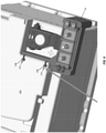
- FIG. 5 which depicts an embodiment of the fuse module 10 with the bus extensions 30, 32 and accompanying structures/features omitted
- the mounting cradle 16 may be provided with ridges 100, castellations 102, and/or other surface features for routing flexible conductors (not shown) to the terminals posts 42, 44 and to the mounting post 60 in a desired manner.
- the mounting cradle 16 may be provided with a stabilizing arm 104 extending therefrom, the stabilizing arm 104 having detents 106, 108 adapted to fit within keyhole-shaped recesses 110, 112 in a battery case 115 for preventing rotation of the fuse module 10 and for providing the fuse module 10 with mechanical strain relief.
- the fuse module 10 of the present disclosure provides numerous advantages relative to pre-fuse boxes that are currently available on the market. For example, owing to the configuration of the above-described mounting cradle 16, with the mounting post 60 extending through, and integral with, the fuse assembly 14, the entire fuse module 10 can be mounted directly to a positive terminal of an automobile battery in close proximity thereto without any flexible conductors extending therebetween. This provides a significant space and material savings relative to conventional pre-fuse boxes. Additionally, the bus extensions 30, 32, which are mechanically joined directly to the bus bar 24, facilitate the provision of terminals with proper mechanical and material characteristics for accommodating low-medium-current fuses in compact configuration.
Landscapes
- Chemical & Material Sciences (AREA)
- Chemical Kinetics & Catalysis (AREA)
- Electrochemistry (AREA)
- General Chemical & Material Sciences (AREA)
- Engineering & Computer Science (AREA)
- Power Engineering (AREA)
- Fuses (AREA)
- Connection Of Batteries Or Terminals (AREA)
Description
- This application claims the benefit of
U.S. Provisional Patent Application No. 62/430,168, filed December 5, 2016 - The disclosure relates generally to the field of circuit protection devices, and relates more particularly to a battery terminal fuse module suitable for automotive battery applications.
- In the global automotive market there has been a trend toward implementing so-called "pre-fuse boxes" disposed within automobile engine compartments and connected to automobile battery terminals. The main purpose of a pre-fuse box in an automobile is to prevent electrical damage that may result from short-circuiting in high-current-conducting wires that may occur in the event of an accident.
- Existing pre-fuse boxes are typically quite large and are mounted adjacent automobile batteries with flexible, conductive leads providing electrical connections therebetween. This configuration requires a great deal of space within an automobile engine compartment where space is already very limited.
- It is with respect to these and other considerations that the present improvements may be useful.
-
US5643693 discloses in accordance with its abstract: 'An electrical power distribution module for use with an automotive vehicle electrical system is adapted to be mounted on the top surface of a standard automotive lead-acid storage battery and connect with a battery terminal extending therefrom. The power distribution module includes a battery post connecting assembly for housing a terminal connector for making electrical connections with the battery terminal and alternator and starter cables, a fuse block for receiving a plurality of fuses associated with separate vehicle electrical circuits, and a harness guide channel for routing a plurality of wires which connect the fuses with their associated circuits. The power distribution module is mounted to lay flat on top of the battery's upper surface with the battery terminal extending upwardly into the module to be engaged by the battery terminal connector. The module does not extend substantially above the highest point of the battery terminal, nor does it extend laterally substantially outside of the battery perimeter. A cover is attached to the power distribution module and has hinged sections which may be opened to provide access to the battery terminal connector and the fuse receptacles.' - This Summary is provided to introduce a selection of concepts in a simplified form that are further described below in the Detailed Description. This Summary is not intended to identify key features or essential features of the claimed subject matter, nor is it intended as an aid in determining the scope of the claimed subject matter.
- A fuse module in accordance with the invention is described in claim 1.
-
-
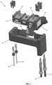
FIG. 1 is an exploded perspective view illustrating a fuse module in accordance with an exemplary embodiment of the present disclosure. -
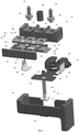
FIG. 2 is an exploded perspective view illustrating a fuse assembly of the fuse module shown inFIG. 1 ; -
FIG. 3 is lateral cross-sectional view illustrating the fuse assembly shown inFIG. 2 ; -
FIG. 4 is longitudinal cross-sectional view illustrating the fuse assembly shown inFIG. 2 ; -
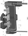
FIG. 5 is perspective view illustrating an alternative embodiment of a fuse module in accordance with the present disclosure; and -
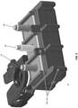
FIG. 6 is perspective view illustrating another alternative embodiment of a fuse module in accordance with the present disclosure. - A battery terminal fuse module in accordance with the present disclosure will now be described more fully with reference to the accompanying drawings, in which preferred embodiments of the battery terminal fuse module are presented. It will be understood, however, that the battery terminal fuse module may be embodied in many different forms and should not be construed as being limited to the embodiments set forth herein. Rather, these embodiments are provided so that this disclosure will convey certain exemplary aspects of the battery terminal fuse module to those skilled in the art. In the drawings, like numbers refer to like elements throughout unless otherwise noted.
- Referring to
FIG. 1 , an exploded view of a battery terminal fuse module 10 (hereinafter "thefuse module 10") in accordance with an exemplary, non-limiting embodiment of the present disclosure is shown. As will be described in greater detail below, thefuse module 10 may be coupled directly to a positive terminal of an automobile battery with no flexible electrical conductors extending therebetween, and may facilitate connection to a plurality of low and medium-current fuses for protecting a variety of electrical loads (e.g., an air conditioning unit, a stereo, etc.) that are powered by the automobile battery. Advantageously, thefuse module 10 includes an integrated mounting structure that allows thefuse module 10 to be implemented in a compact, space-saving form factor relative to pre-fuse boxes that are currently available on the market. - For the sake of convenience and clarity, terms such as "front," "rear," "top," "bottom," "up," "down," "vertical," and "horizontal" may be used herein to describe the relative placement and orientation of various components of the
fuse module 10, each with respect to the geometry and orientation of thefuse module 10 as it appears inFIG. 1 . Said terminology will include the words specifically mentioned, derivatives thereof, and words of similar import. - The
fuse module 10 includes abattery clamp 12, afuse assembly 14, and amounting cradle 16 that are coupled together in a vertically stacked arrangement as further described below. Thebattery clamp 12 may be formed of metal or any other suitably rigid, electrically conductive material and may include a ferrule portion 18 (best shown inFig. 2 ) for removably fastening thebattery clamp 12 to a positive terminal of an automobile battery. Thebattery clamp 12 may further include a substantially planar, T-shaped terminal portion 20 that extends generally horizontally from the front of theferrule portion 18. Theterminal portion 20 and theferrule portion 18 of thebattery clamp 12 may be formed from a single piece of material (e.g., stamped from a single sheet of metal) or may be formed from separate pieces of material that are welded, clinched, or otherwise joined together in a manner that provides robust electrical communication therebetween. It is contemplated that a ledge, block, or other support structure may be formed on, or affixed to, an underside of theterminal portion 20 to support thebattery clamp 12 against the weight of the cantileveredfuse assembly 14 and mountingcradle 16 to reduce mechanical stress on the connection between theferrule portion 18 and a battery terminal. - Referring now to the exploded view shown in
FIG. 2 , thefuse assembly 14 includes an elongate mounting block 22 formed of an electrically insulting material (e.g., ceramic, plastic, polymer, etc.). Thefuse assembly 14 includes a substantiallyplanar bus bar 24 formed of an electrically conductive material (e.g., copper) that extends along a bottom surface of the mounting block 22. Thebus bar 24 may sit atop theterminal portion 20 of thebattery clamp 12 in electrical communication therewith. Thefuse assembly 14 includes a plurality of fuses 261, 262, 263 that include respective fuse terminals 281, 282, 283 disposed on a top surface of the mounting block 22 and connected to thebus bar 24 by respectivefusible elements bus bar 24 and the fuses 261, 262, 263 may be formed from a single piece of conductive material (e.g., stamped from a single sheet of copper) and may be bent or wrapped about the faces of the mounting block 22. In a non-limiting, exemplary embodiment, thebus bar 24 and the fuses 261, 262, 263 may be formed of 1-millimeter-thick copper sheet, and each of the fuses 261, 262, 263 may have a rating of 80 amps. It will be appreciated that thebus bar 24 and the fuses 261, 262, 263 are not limited in this regard, and that thebus bar 24 and the fuses 261, 262, 263 may be formed of various other conductive materials and/or with different thicknesses to achieve different current ratings. - The
fuse assembly 14 may further includebus extensions bus bar 24. Eachbus extension oriented base portions extension terminal portions base portions bus bar 24 in a manner that provides robust electrical communication therebetween. In a non-limiting, exemplary embodiment, thebus extensions thick bus bar 24 described above) to facilitate connection to fuses having lower amperage ratings (e.g., 5-40 amps) than the fuses 261, 262, 263 described above. The implementation of such lower amperage fuses via thebus extensions - The
fuse assembly 14 includes electricallyconductive terminal posts polygonal flanges flanges polygonal bores terminal posts respective apertures FIG. 1 ). Thebores flanges flanges flanges terminal posts terminal posts terminal posts terminal posts terminal posts fusible elements bus bar 24, and thebattery clamp 12, with the fuses 261, 263 providing over-current protection between the automobile battery and such electrical systems or components. - The
mounting cradle 16 may be a generally rectangular, cup-shaped member formed of an electrically insulating material (e.g., plastic, polymer, etc.). Themounting cradle 16 may hold theterminal portion 20 of thebattery clamp 12 and the bottom of thefuse assembly 14, substantially covering the front and sides of thefuse assembly 14, with theterminal portion 20 extending through arecess 57 in the rear of themounting cradle 16. A threadedmounting post 60 may be rigidly attached to, and may extend vertically from, afloor 62 of themounting cradle 16. In a non-limiting example, aflange 59 extending from a lower end of themounting post 60 may be overmolded within thefloor 62 of themounting cradle 16. Themounting post 60 may extend upwardly through anaperture 61 in theterminal portion 20 of thebattery clamp 12, through anaperture 63 in thebus bar 24, through abore 64 formed in the mounting block 22, and through anaperture 65 in the fuse terminal 282 of the fuse 262 (see alsoFIG. 3 ). Thus, as with theterminal posts mounting post 60 and secured against the fuse terminal 282 with a nut (not shown) that may be tightened onto themounting post 60. Additionally, tightening a nut onto the mountingpost 60 may secure the mountingcradle 16, thebattery clamp 12, and thefuse assembly 14 together in a vertically stacked arrangement. The mountingpost 60 may be electrically insulated from thebus bar 24, such as by physical separation and/or electrically insulating material disposed therebetween, to prevent electrical current from bypassing thefusible element 302 and flowing from thebus bar 24 to the fuse terminal 282 via the mountingpost 60. - Referring now to the cross-sectional view of the
module 10 shown inFIG. 3 , atubular sleeve 66 may be disposed within thebore 64 in the mounting block 22 and may surround the mountingpost 60 vertically intermediate thebus bar 24 and the fuse terminal 282, with a bottom of thesleeve 66 engaging or proximate a top of thebus bar 24 and with a top of thesleeve 66 engaging or proximate a bottom of the fuse terminal 282. In a non-limiting embodiment of thefuse module 10, thesleeve 66 may be formed of metal to provide an electrically-conductive pathway (i.e., a shunt) extending directly between thebus bar 24 and the fuse terminal 282. Such a configuration may be appropriate in applications where it is desirable to bypass thefusible element 302 and provide an unprotected electrical path from an automobile battery through thefuse module 10 to electrical systems/components that may be protected by fuses elsewhere in an automobile. In an alternative embodiment of thefuse module 10, thesleeve 66 may be formed of a non-conductive material (e.g., ceramic, plastic, etc.), whereby the only electrically-conductive path between thebus bar 24 and the fuse terminal 282 is through thefusible element 302. - The
fuse assembly 14 may further include acover 70 that may be affixed to a front of the mounting block 22, such as with mechanical fasteners or structures, adhesives, welding, etc. Thecover 70 may be disposed over thefusible elements fusible elements fusible elements - Referring now to
FIG. 4 , thebus extensions fuse assembly 14. For example, theterminal portion 38 of thebus extension 30 may have forkedterminals 76, 78 (best shown inFIG. 2 ) for receiving legs of respective blade fuses 80, 82. The blade fuses 80, 82 may be seated within respective recesses formed in the mountingcradle 16 and mounting block 22 and may be connected to respectiveelectrical conductors 84, 86 (see alsoFIG. 1 ) that extend through apertures in the bottom of the mountingcradle 16. - The top edge of the
terminal portion 40 of thebus extension 32 may facilitate connection to slotted cartridge fuses 88, 90 which may be seated within respective recesses formed in the mountingcradle 16 and mounting block 22 and may be and connected to respectiveelectrical conductors 92, 94 (see alsoFIG. 1 ) that extend through apertures in the bottom of the mountingcradle 16. As described above, the reduced thickness of thebus extension 32 relative to thebus bar 24 allows a conventional slotted cartridge fuse adapted for connection to a 0.8 millimeter terminal to be connected to thefuse assembly 14, for example. - It is contemplated that the mounting
cradle 16 of thefuse module 10 may be provided with numerous features for accommodating various application environments. For example, referring toFIG. 5 , which depicts an embodiment of thefuse module 10 with thebus extensions cradle 16 may be provided with ridges 100, castellations 102, and/or other surface features for routing flexible conductors (not shown) to the terminals posts 42, 44 and to the mountingpost 60 in a desired manner. Referring to another example shown inFIG. 6 , it is contemplated that the mountingcradle 16 may be provided with a stabilizing arm 104 extending therefrom, the stabilizing arm 104 havingdetents recesses battery case 115 for preventing rotation of thefuse module 10 and for providing thefuse module 10 with mechanical strain relief. - It will be appreciated by those of ordinary skill in the art that the
fuse module 10 of the present disclosure provides numerous advantages relative to pre-fuse boxes that are currently available on the market. For example, owing to the configuration of the above-described mountingcradle 16, with the mountingpost 60 extending through, and integral with, thefuse assembly 14, theentire fuse module 10 can be mounted directly to a positive terminal of an automobile battery in close proximity thereto without any flexible conductors extending therebetween. This provides a significant space and material savings relative to conventional pre-fuse boxes. Additionally, thebus extensions bus bar 24, facilitate the provision of terminals with proper mechanical and material characteristics for accommodating low-medium-current fuses in compact configuration.
Claims (9)
- A fuse module (10) comprising:an electrically conductive battery clamp (12) adapted for connection to a battery terminal;a fuse assembly (14) comprising:a mounting block (22) formed of an electrically insulating material;an electrically conductive bus bar (24) disposed on a first side of the mounting block (22) in contact with the battery clamp (12);characterised by a plurality of fuse terminals (281, 282, 283 ) disposed on a second side of the mounting block (22) opposite the first side and connected to the bus bar (24) by respective fusible elements (301, 302, 303); andan electrically conductive terminal post (42, 44) extending through one of the fuse terminals (281, 282, 283) for facilitating connection to a first electrical component; anda mounting cradle (16) holding the fuse assembly (14) and at least a portion of the battery clamp (12), the mounting cradle (16) including a mounting post (60) extending through the battery clamp (12), the bus bar (24), the mounting block (22), and one of the fuse terminals (281, 282, 283 ) for facilitating connection to a second electrical component and for securing the battery clamp (12), the fuse assembly (14), and the mounting cradle (16) together in a stacked arrangement, wherein the mounting post (60) is surrounded by a tubular sleeve (66) that extends between the bus bar (24) and the fuse terminal (281, 282, 283 ) through which the mounting post (60) extends.
- The fuse module (10) of claim 1, wherein the tubular sleeve (66) is formed of an electrically conductive material and provides an electrically conductive path between the bus bar (24) and the fuse terminal (281, 282, 283 ) through which the mounting post (60) extends.
- The fuse module (10) of claim 1, wherein the tubular sleeve (66) is formed of an electrically insulating material.
- The fuse module (10) of claim 1, further comprising an electrically conductive bus extension (30, 32) extending from the bus bar (24) for facilitating connection to a fuse.
- The fuse module (10) of claim 4, wherein the bus extension (30, 32) is forked for receiving a blade fuse (80, 82).
- The fuse module (10) of claim 4, wherein the bus extension (30, 32) defines a flat edge adapted to receive a slotted fuse.
- The fuse module (10) of claim 4, wherein the bus extension (30, 32) differs from the bus bar (24) with respect to at least one of material and thickness such that the bus extension (30, 32) has a lower current carrying capacity than the bus bar (24).
- The fuse module (10) of claim 1, wherein at least one of the mounting block (22) and the mounting cradle (16) defines a recess for holding a fuse.
- The fuse module (10) of claim 1, wherein the electrically conductive battery clamp (12) includes a ferrule portion (18)for connection to the battery terminal and further includes a terminal portion extending from the ferrule portion (18).
Applications Claiming Priority (2)
| Application Number | Priority Date | Filing Date | Title |
|---|---|---|---|
| US201662430168P | 2016-12-05 | 2016-12-05 | |
| PCT/US2017/064747 WO2018106715A1 (en) | 2016-12-05 | 2017-12-05 | Battery terminal fuse module |
Publications (3)
| Publication Number | Publication Date |
|---|---|
| EP3552221A1 EP3552221A1 (en) | 2019-10-16 |
| EP3552221A4 EP3552221A4 (en) | 2020-06-03 |
| EP3552221B1 true EP3552221B1 (en) | 2022-03-16 |
Family
ID=62491317
Family Applications (1)
| Application Number | Title | Priority Date | Filing Date |
|---|---|---|---|
| EP17878360.1A Active EP3552221B1 (en) | 2016-12-05 | 2017-12-05 | Battery terminal fuse module |
Country Status (4)
| Country | Link |
|---|---|
| US (2) | US10148044B2 (en) |
| EP (1) | EP3552221B1 (en) |
| JP (1) | JP7033595B2 (en) |
| WO (1) | WO2018106715A1 (en) |
Families Citing this family (6)
| Publication number | Priority date | Publication date | Assignee | Title |
|---|---|---|---|---|
| US11037750B2 (en) * | 2018-09-13 | 2021-06-15 | Yazaki North America, Inc. | High current fuse block |
| KR102634405B1 (en) * | 2018-12-10 | 2024-02-06 | 현대자동차주식회사 | Junction connector assembly integrated with fuse |
| US11355300B2 (en) * | 2019-05-07 | 2022-06-07 | Littelfuse, Inc. | Active/passive automotive fuse module |
| US12020882B2 (en) | 2021-08-06 | 2024-06-25 | Littelfuse, Inc. | Fuse assembly including anti-rotation device |
| US12387898B2 (en) * | 2023-12-08 | 2025-08-12 | Littelfuse, Inc. | Jump stud fuse module |
| EP4654241A1 (en) * | 2024-05-21 | 2025-11-26 | Aptiv Technologies AG | Fuse holder device for high-power electrical circuit |
Family Cites Families (17)
| Publication number | Priority date | Publication date | Assignee | Title |
|---|---|---|---|---|
| US5643693A (en) * | 1995-10-30 | 1997-07-01 | Yazaki Corporation | Battery-mounted power distribution module |
| US6642633B1 (en) * | 2001-06-27 | 2003-11-04 | Yazaki North America, Inc. | Power management assembly |
| US6902434B2 (en) | 2002-07-23 | 2005-06-07 | Cooper Technologies Company | Battery fuse bus bar assembly |
| US6855008B1 (en) * | 2003-10-06 | 2005-02-15 | Royal Die & Stamping Co., Inc. | Fuse holder with adjustable terminals |
| JP4181028B2 (en) | 2003-12-22 | 2008-11-12 | 矢崎総業株式会社 | Electrical junction box |
| US7990738B2 (en) * | 2008-04-02 | 2011-08-02 | Littelfuse, Inc. | Master fuse module |
| CN102084517A (en) | 2008-05-15 | 2011-06-01 | 江森自控帅福得先进能源动力系统有限责任公司 | Battery system |
| JP5189920B2 (en) * | 2008-07-25 | 2013-04-24 | 矢崎総業株式会社 | Fusible link unit |
| US8056305B1 (en) * | 2008-09-30 | 2011-11-15 | Bank Of America Corporation | Automatic strapping and bagging of funds |
| JP5328459B2 (en) | 2009-04-10 | 2013-10-30 | 矢崎総業株式会社 | Fuse unit |
| US8269596B2 (en) * | 2009-12-23 | 2012-09-18 | Cooper Technologies Company | Universal dual stud modular fuse holder assembly for bussed and non-bussed power connections |
| US8665056B2 (en) | 2010-05-18 | 2014-03-04 | Littlefuse, Inc. | Fuse assembly |
| US9093768B1 (en) * | 2014-02-14 | 2015-07-28 | Royal Die & Stamping Co., Inc. | One-piece fusible battery terminal clamp |
| US20150325934A1 (en) * | 2014-02-14 | 2015-11-12 | Royal Die & Stamping Co., Inc. | One-piece fusible battery terminal clamp |
| JP6014084B2 (en) | 2014-07-16 | 2016-10-25 | 矢崎総業株式会社 | Fuse unit manufacturing method, molding method using mold structure, and fuse unit |
| JP6430834B2 (en) | 2015-01-14 | 2018-11-28 | 矢崎総業株式会社 | Fuse unit and method for assembling fuse unit |
| US9728363B2 (en) * | 2015-11-25 | 2017-08-08 | Sumitomo Wiring Systems, Ltd. | Pre-fuse assembly with horizontal jump post |
-
2017
- 2017-12-05 WO PCT/US2017/064747 patent/WO2018106715A1/en not_active Ceased
- 2017-12-05 EP EP17878360.1A patent/EP3552221B1/en active Active
- 2017-12-05 US US15/832,477 patent/US10148044B2/en active Active
- 2017-12-05 JP JP2019530192A patent/JP7033595B2/en active Active
-
2018
- 2018-10-19 US US16/165,684 patent/US10446989B2/en active Active
Also Published As
| Publication number | Publication date |
|---|---|
| US20180205188A1 (en) | 2018-07-19 |
| US20190058294A1 (en) | 2019-02-21 |
| WO2018106715A1 (en) | 2018-06-14 |
| EP3552221A1 (en) | 2019-10-16 |
| JP7033595B2 (en) | 2022-03-10 |
| US10446989B2 (en) | 2019-10-15 |
| JP2020514952A (en) | 2020-05-21 |
| US10148044B2 (en) | 2018-12-04 |
| EP3552221A4 (en) | 2020-06-03 |
Similar Documents
| Publication | Publication Date | Title |
|---|---|---|
| EP3552221B1 (en) | Battery terminal fuse module | |
| US11282667B2 (en) | Low profile integrated fuse module | |
| JP6581958B2 (en) | Voltage detection structure and voltage detection module | |
| US11043721B2 (en) | Connection structure of conductor and conductive module | |
| KR20150106915A (en) | Battery distribution unit | |
| JP2018097986A (en) | Conductor unit fixing structure | |
| US11189450B2 (en) | Low profile integrated fuse module | |
| CN108701800A (en) | Interconnection module | |
| US11062870B2 (en) | Integrated fuse module | |
| EP4104197B1 (en) | Low profile integrated fuse module | |
| JP2015220769A (en) | Connection conductor unit | |
| US11081814B2 (en) | Wiring module | |
| CN110854770A (en) | Power supply terminal structure, electrical connection box and wire harness | |
| EP4567855A1 (en) | Jump stud fuse module | |
| WO2009029061A1 (en) | Battery terminal connector bar with integral circuit protection |
Legal Events
| Date | Code | Title | Description |
|---|---|---|---|
| STAA | Information on the status of an ep patent application or granted ep patent |
Free format text: STATUS: THE INTERNATIONAL PUBLICATION HAS BEEN MADE |
|
| PUAI | Public reference made under article 153(3) epc to a published international application that has entered the european phase |
Free format text: ORIGINAL CODE: 0009012 |
|
| STAA | Information on the status of an ep patent application or granted ep patent |
Free format text: STATUS: REQUEST FOR EXAMINATION WAS MADE |
|
| 17P | Request for examination filed |
Effective date: 20190705 |
|
| AK | Designated contracting states |
Kind code of ref document: A1 Designated state(s): AL AT BE BG CH CY CZ DE DK EE ES FI FR GB GR HR HU IE IS IT LI LT LU LV MC MK MT NL NO PL PT RO RS SE SI SK SM TR |
|
| AX | Request for extension of the european patent |
Extension state: BA ME |
|
| DAV | Request for validation of the european patent (deleted) | ||
| DAX | Request for extension of the european patent (deleted) | ||
| A4 | Supplementary search report drawn up and despatched |
Effective date: 20200508 |
|
| RIC1 | Information provided on ipc code assigned before grant |
Ipc: H01H 85/20 20060101AFI20200501BHEP |
|
| GRAP | Despatch of communication of intention to grant a patent |
Free format text: ORIGINAL CODE: EPIDOSNIGR1 |
|
| STAA | Information on the status of an ep patent application or granted ep patent |
Free format text: STATUS: GRANT OF PATENT IS INTENDED |
|
| INTG | Intention to grant announced |
Effective date: 20210901 |
|
| GRAJ | Information related to disapproval of communication of intention to grant by the applicant or resumption of examination proceedings by the epo deleted |
Free format text: ORIGINAL CODE: EPIDOSDIGR1 |
|
| STAA | Information on the status of an ep patent application or granted ep patent |
Free format text: STATUS: REQUEST FOR EXAMINATION WAS MADE |
|
| GRAS | Grant fee paid |
Free format text: ORIGINAL CODE: EPIDOSNIGR3 |
|
| STAA | Information on the status of an ep patent application or granted ep patent |
Free format text: STATUS: GRANT OF PATENT IS INTENDED |
|
| GRAP | Despatch of communication of intention to grant a patent |
Free format text: ORIGINAL CODE: EPIDOSNIGR1 |
|
| GRAA | (expected) grant |
Free format text: ORIGINAL CODE: 0009210 |
|
| STAA | Information on the status of an ep patent application or granted ep patent |
Free format text: STATUS: THE PATENT HAS BEEN GRANTED |
|
| INTC | Intention to grant announced (deleted) | ||
| INTG | Intention to grant announced |
Effective date: 20220125 |
|
| AK | Designated contracting states |
Kind code of ref document: B1 Designated state(s): AL AT BE BG CH CY CZ DE DK EE ES FI FR GB GR HR HU IE IS IT LI LT LU LV MC MK MT NL NO PL PT RO RS SE SI SK SM TR |
|
| REG | Reference to a national code |
Ref country code: GB Ref legal event code: FG4D |
|
| REG | Reference to a national code |
Ref country code: CH Ref legal event code: EP Ref country code: DE Ref legal event code: R096 Ref document number: 602017054797 Country of ref document: DE |
|
| REG | Reference to a national code |
Ref country code: IE Ref legal event code: FG4D |
|
| REG | Reference to a national code |
Ref country code: AT Ref legal event code: REF Ref document number: 1476491 Country of ref document: AT Kind code of ref document: T Effective date: 20220415 |
|
| REG | Reference to a national code |
Ref country code: LT Ref legal event code: MG9D |
|
| REG | Reference to a national code |
Ref country code: NL Ref legal event code: MP Effective date: 20220316 |
|
| PG25 | Lapsed in a contracting state [announced via postgrant information from national office to epo] |
Ref country code: SE Free format text: LAPSE BECAUSE OF FAILURE TO SUBMIT A TRANSLATION OF THE DESCRIPTION OR TO PAY THE FEE WITHIN THE PRESCRIBED TIME-LIMIT Effective date: 20220316 Ref country code: RS Free format text: LAPSE BECAUSE OF FAILURE TO SUBMIT A TRANSLATION OF THE DESCRIPTION OR TO PAY THE FEE WITHIN THE PRESCRIBED TIME-LIMIT Effective date: 20220316 Ref country code: NO Free format text: LAPSE BECAUSE OF FAILURE TO SUBMIT A TRANSLATION OF THE DESCRIPTION OR TO PAY THE FEE WITHIN THE PRESCRIBED TIME-LIMIT Effective date: 20220616 Ref country code: LT Free format text: LAPSE BECAUSE OF FAILURE TO SUBMIT A TRANSLATION OF THE DESCRIPTION OR TO PAY THE FEE WITHIN THE PRESCRIBED TIME-LIMIT Effective date: 20220316 Ref country code: HR Free format text: LAPSE BECAUSE OF FAILURE TO SUBMIT A TRANSLATION OF THE DESCRIPTION OR TO PAY THE FEE WITHIN THE PRESCRIBED TIME-LIMIT Effective date: 20220316 Ref country code: BG Free format text: LAPSE BECAUSE OF FAILURE TO SUBMIT A TRANSLATION OF THE DESCRIPTION OR TO PAY THE FEE WITHIN THE PRESCRIBED TIME-LIMIT Effective date: 20220616 |
|
| REG | Reference to a national code |
Ref country code: AT Ref legal event code: MK05 Ref document number: 1476491 Country of ref document: AT Kind code of ref document: T Effective date: 20220316 |
|
| PG25 | Lapsed in a contracting state [announced via postgrant information from national office to epo] |
Ref country code: LV Free format text: LAPSE BECAUSE OF FAILURE TO SUBMIT A TRANSLATION OF THE DESCRIPTION OR TO PAY THE FEE WITHIN THE PRESCRIBED TIME-LIMIT Effective date: 20220316 Ref country code: GR Free format text: LAPSE BECAUSE OF FAILURE TO SUBMIT A TRANSLATION OF THE DESCRIPTION OR TO PAY THE FEE WITHIN THE PRESCRIBED TIME-LIMIT Effective date: 20220617 Ref country code: FI Free format text: LAPSE BECAUSE OF FAILURE TO SUBMIT A TRANSLATION OF THE DESCRIPTION OR TO PAY THE FEE WITHIN THE PRESCRIBED TIME-LIMIT Effective date: 20220316 |
|
| PG25 | Lapsed in a contracting state [announced via postgrant information from national office to epo] |
Ref country code: NL Free format text: LAPSE BECAUSE OF FAILURE TO SUBMIT A TRANSLATION OF THE DESCRIPTION OR TO PAY THE FEE WITHIN THE PRESCRIBED TIME-LIMIT Effective date: 20220316 |
|
| PG25 | Lapsed in a contracting state [announced via postgrant information from national office to epo] |
Ref country code: SM Free format text: LAPSE BECAUSE OF FAILURE TO SUBMIT A TRANSLATION OF THE DESCRIPTION OR TO PAY THE FEE WITHIN THE PRESCRIBED TIME-LIMIT Effective date: 20220316 Ref country code: SK Free format text: LAPSE BECAUSE OF FAILURE TO SUBMIT A TRANSLATION OF THE DESCRIPTION OR TO PAY THE FEE WITHIN THE PRESCRIBED TIME-LIMIT Effective date: 20220316 Ref country code: RO Free format text: LAPSE BECAUSE OF FAILURE TO SUBMIT A TRANSLATION OF THE DESCRIPTION OR TO PAY THE FEE WITHIN THE PRESCRIBED TIME-LIMIT Effective date: 20220316 Ref country code: PT Free format text: LAPSE BECAUSE OF FAILURE TO SUBMIT A TRANSLATION OF THE DESCRIPTION OR TO PAY THE FEE WITHIN THE PRESCRIBED TIME-LIMIT Effective date: 20220718 Ref country code: ES Free format text: LAPSE BECAUSE OF FAILURE TO SUBMIT A TRANSLATION OF THE DESCRIPTION OR TO PAY THE FEE WITHIN THE PRESCRIBED TIME-LIMIT Effective date: 20220316 Ref country code: EE Free format text: LAPSE BECAUSE OF FAILURE TO SUBMIT A TRANSLATION OF THE DESCRIPTION OR TO PAY THE FEE WITHIN THE PRESCRIBED TIME-LIMIT Effective date: 20220316 Ref country code: CZ Free format text: LAPSE BECAUSE OF FAILURE TO SUBMIT A TRANSLATION OF THE DESCRIPTION OR TO PAY THE FEE WITHIN THE PRESCRIBED TIME-LIMIT Effective date: 20220316 Ref country code: AT Free format text: LAPSE BECAUSE OF FAILURE TO SUBMIT A TRANSLATION OF THE DESCRIPTION OR TO PAY THE FEE WITHIN THE PRESCRIBED TIME-LIMIT Effective date: 20220316 |
|
| PG25 | Lapsed in a contracting state [announced via postgrant information from national office to epo] |
Ref country code: PL Free format text: LAPSE BECAUSE OF FAILURE TO SUBMIT A TRANSLATION OF THE DESCRIPTION OR TO PAY THE FEE WITHIN THE PRESCRIBED TIME-LIMIT Effective date: 20220316 Ref country code: IS Free format text: LAPSE BECAUSE OF FAILURE TO SUBMIT A TRANSLATION OF THE DESCRIPTION OR TO PAY THE FEE WITHIN THE PRESCRIBED TIME-LIMIT Effective date: 20220716 Ref country code: AL Free format text: LAPSE BECAUSE OF FAILURE TO SUBMIT A TRANSLATION OF THE DESCRIPTION OR TO PAY THE FEE WITHIN THE PRESCRIBED TIME-LIMIT Effective date: 20220316 |
|
| REG | Reference to a national code |
Ref country code: DE Ref legal event code: R097 Ref document number: 602017054797 Country of ref document: DE |
|
| PLBE | No opposition filed within time limit |
Free format text: ORIGINAL CODE: 0009261 |
|
| STAA | Information on the status of an ep patent application or granted ep patent |
Free format text: STATUS: NO OPPOSITION FILED WITHIN TIME LIMIT |
|
| PG25 | Lapsed in a contracting state [announced via postgrant information from national office to epo] |
Ref country code: DK Free format text: LAPSE BECAUSE OF FAILURE TO SUBMIT A TRANSLATION OF THE DESCRIPTION OR TO PAY THE FEE WITHIN THE PRESCRIBED TIME-LIMIT Effective date: 20220316 |
|
| 26N | No opposition filed |
Effective date: 20221219 |
|
| PG25 | Lapsed in a contracting state [announced via postgrant information from national office to epo] |
Ref country code: SI Free format text: LAPSE BECAUSE OF FAILURE TO SUBMIT A TRANSLATION OF THE DESCRIPTION OR TO PAY THE FEE WITHIN THE PRESCRIBED TIME-LIMIT Effective date: 20220316 |
|
| P01 | Opt-out of the competence of the unified patent court (upc) registered |
Effective date: 20230607 |
|
| REG | Reference to a national code |
Ref country code: CH Ref legal event code: PL |
|
| REG | Reference to a national code |
Ref country code: BE Ref legal event code: MM Effective date: 20221231 |
|
| PG25 | Lapsed in a contracting state [announced via postgrant information from national office to epo] |
Ref country code: LU Free format text: LAPSE BECAUSE OF NON-PAYMENT OF DUE FEES Effective date: 20221205 |
|
| PG25 | Lapsed in a contracting state [announced via postgrant information from national office to epo] |
Ref country code: LI Free format text: LAPSE BECAUSE OF NON-PAYMENT OF DUE FEES Effective date: 20221231 Ref country code: IE Free format text: LAPSE BECAUSE OF NON-PAYMENT OF DUE FEES Effective date: 20221205 Ref country code: CH Free format text: LAPSE BECAUSE OF NON-PAYMENT OF DUE FEES Effective date: 20221231 |
|
| PG25 | Lapsed in a contracting state [announced via postgrant information from national office to epo] |
Ref country code: BE Free format text: LAPSE BECAUSE OF NON-PAYMENT OF DUE FEES Effective date: 20221231 |
|
| PG25 | Lapsed in a contracting state [announced via postgrant information from national office to epo] |
Ref country code: HU Free format text: LAPSE BECAUSE OF FAILURE TO SUBMIT A TRANSLATION OF THE DESCRIPTION OR TO PAY THE FEE WITHIN THE PRESCRIBED TIME-LIMIT; INVALID AB INITIO Effective date: 20171205 |
|
| PG25 | Lapsed in a contracting state [announced via postgrant information from national office to epo] |
Ref country code: CY Free format text: LAPSE BECAUSE OF FAILURE TO SUBMIT A TRANSLATION OF THE DESCRIPTION OR TO PAY THE FEE WITHIN THE PRESCRIBED TIME-LIMIT Effective date: 20220316 |
|
| PG25 | Lapsed in a contracting state [announced via postgrant information from national office to epo] |
Ref country code: MK Free format text: LAPSE BECAUSE OF FAILURE TO SUBMIT A TRANSLATION OF THE DESCRIPTION OR TO PAY THE FEE WITHIN THE PRESCRIBED TIME-LIMIT Effective date: 20220316 |
|
| PG25 | Lapsed in a contracting state [announced via postgrant information from national office to epo] |
Ref country code: MC Free format text: LAPSE BECAUSE OF FAILURE TO SUBMIT A TRANSLATION OF THE DESCRIPTION OR TO PAY THE FEE WITHIN THE PRESCRIBED TIME-LIMIT Effective date: 20220316 |
|
| PG25 | Lapsed in a contracting state [announced via postgrant information from national office to epo] |
Ref country code: MC Free format text: LAPSE BECAUSE OF FAILURE TO SUBMIT A TRANSLATION OF THE DESCRIPTION OR TO PAY THE FEE WITHIN THE PRESCRIBED TIME-LIMIT Effective date: 20220316 |
|
| PG25 | Lapsed in a contracting state [announced via postgrant information from national office to epo] |
Ref country code: MT Free format text: LAPSE BECAUSE OF FAILURE TO SUBMIT A TRANSLATION OF THE DESCRIPTION OR TO PAY THE FEE WITHIN THE PRESCRIBED TIME-LIMIT Effective date: 20220316 |
|
| PGFP | Annual fee paid to national office [announced via postgrant information from national office to epo] |
Ref country code: FR Payment date: 20250930 Year of fee payment: 9 |
|
| PG25 | Lapsed in a contracting state [announced via postgrant information from national office to epo] |
Ref country code: TR Free format text: LAPSE BECAUSE OF FAILURE TO SUBMIT A TRANSLATION OF THE DESCRIPTION OR TO PAY THE FEE WITHIN THE PRESCRIBED TIME-LIMIT Effective date: 20220316 |
|
| PGFP | Annual fee paid to national office [announced via postgrant information from national office to epo] |
Ref country code: DE Payment date: 20250930 Year of fee payment: 9 |
|
| PGFP | Annual fee paid to national office [announced via postgrant information from national office to epo] |
Ref country code: GB Payment date: 20251001 Year of fee payment: 9 |
|
| PGFP | Annual fee paid to national office [announced via postgrant information from national office to epo] |
Ref country code: IT Payment date: 20251121 Year of fee payment: 9 |