EP3551971B1 - Optischer füllstandsensor für herausnehmbaren waschhilfebehälter - Google Patents
Optischer füllstandsensor für herausnehmbaren waschhilfebehälter Download PDFInfo
- Publication number
- EP3551971B1 EP3551971B1 EP17817972.7A EP17817972A EP3551971B1 EP 3551971 B1 EP3551971 B1 EP 3551971B1 EP 17817972 A EP17817972 A EP 17817972A EP 3551971 B1 EP3551971 B1 EP 3551971B1
- Authority
- EP
- European Patent Office
- Prior art keywords
- light
- liquid
- reservoir
- sensing system
- level sensing
- Prior art date
- Legal status (The legal status is an assumption and is not a legal conclusion. Google has not performed a legal analysis and makes no representation as to the accuracy of the status listed.)
- Active
Links
Images

Classifications
-
- G—PHYSICS
- G01—MEASURING; TESTING
- G01F—MEASURING VOLUME, VOLUME FLOW, MASS FLOW OR LIQUID LEVEL; METERING BY VOLUME
- G01F23/00—Indicating or measuring liquid level or level of fluent solid material, e.g. indicating in terms of volume or indicating by means of an alarm
- G01F23/22—Indicating or measuring liquid level or level of fluent solid material, e.g. indicating in terms of volume or indicating by means of an alarm by measuring physical variables, other than linear dimensions, pressure or weight, dependent on the level to be measured, e.g. by difference of heat transfer of steam or water
- G01F23/28—Indicating or measuring liquid level or level of fluent solid material, e.g. indicating in terms of volume or indicating by means of an alarm by measuring physical variables, other than linear dimensions, pressure or weight, dependent on the level to be measured, e.g. by difference of heat transfer of steam or water by measuring the variations of parameters of electromagnetic or acoustic waves applied directly to the liquid or fluent solid material
- G01F23/284—Electromagnetic waves
- G01F23/292—Light, e.g. infrared or ultraviolet
-
- D—TEXTILES; PAPER
- D06—TREATMENT OF TEXTILES OR THE LIKE; LAUNDERING; FLEXIBLE MATERIALS NOT OTHERWISE PROVIDED FOR
- D06F—LAUNDERING, DRYING, IRONING, PRESSING OR FOLDING TEXTILE ARTICLES
- D06F39/00—Details of washing machines not specific to a single type of machines covered by groups D06F9/00 - D06F27/00
- D06F39/02—Devices for adding soap or other washing agents
- D06F39/022—Devices for adding soap or other washing agents in a liquid state
-
- D—TEXTILES; PAPER
- D06—TREATMENT OF TEXTILES OR THE LIKE; LAUNDERING; FLEXIBLE MATERIALS NOT OTHERWISE PROVIDED FOR
- D06F—LAUNDERING, DRYING, IRONING, PRESSING OR FOLDING TEXTILE ARTICLES
- D06F33/00—Control of operations performed in washing machines or washer-dryers
- D06F33/30—Control of washing machines characterised by the purpose or target of the control
- D06F33/32—Control of operational steps, e.g. optimisation or improvement of operational steps depending on the condition of the laundry
- D06F33/37—Control of operational steps, e.g. optimisation or improvement of operational steps depending on the condition of the laundry of metering of detergents or additives
-
- D—TEXTILES; PAPER
- D06—TREATMENT OF TEXTILES OR THE LIKE; LAUNDERING; FLEXIBLE MATERIALS NOT OTHERWISE PROVIDED FOR
- D06F—LAUNDERING, DRYING, IRONING, PRESSING OR FOLDING TEXTILE ARTICLES
- D06F39/00—Details of washing machines not specific to a single type of machines covered by groups D06F9/00 - D06F27/00
- D06F39/02—Devices for adding soap or other washing agents
-
- G—PHYSICS
- G01—MEASURING; TESTING
- G01F—MEASURING VOLUME, VOLUME FLOW, MASS FLOW OR LIQUID LEVEL; METERING BY VOLUME
- G01F23/00—Indicating or measuring liquid level or level of fluent solid material, e.g. indicating in terms of volume or indicating by means of an alarm
- G01F23/22—Indicating or measuring liquid level or level of fluent solid material, e.g. indicating in terms of volume or indicating by means of an alarm by measuring physical variables, other than linear dimensions, pressure or weight, dependent on the level to be measured, e.g. by difference of heat transfer of steam or water
- G01F23/28—Indicating or measuring liquid level or level of fluent solid material, e.g. indicating in terms of volume or indicating by means of an alarm by measuring physical variables, other than linear dimensions, pressure or weight, dependent on the level to be measured, e.g. by difference of heat transfer of steam or water by measuring the variations of parameters of electromagnetic or acoustic waves applied directly to the liquid or fluent solid material
- G01F23/284—Electromagnetic waves
- G01F23/292—Light, e.g. infrared or ultraviolet
- G01F23/2921—Light, e.g. infrared or ultraviolet for discrete levels
- G01F23/2922—Light, e.g. infrared or ultraviolet for discrete levels with light-conducting sensing elements, e.g. prisms
- G01F23/2924—Light, e.g. infrared or ultraviolet for discrete levels with light-conducting sensing elements, e.g. prisms for several discrete levels, e.g. with more than one light-conducting sensing element
-
- G—PHYSICS
- G01—MEASURING; TESTING
- G01F—MEASURING VOLUME, VOLUME FLOW, MASS FLOW OR LIQUID LEVEL; METERING BY VOLUME
- G01F23/00—Indicating or measuring liquid level or level of fluent solid material, e.g. indicating in terms of volume or indicating by means of an alarm
- G01F23/22—Indicating or measuring liquid level or level of fluent solid material, e.g. indicating in terms of volume or indicating by means of an alarm by measuring physical variables, other than linear dimensions, pressure or weight, dependent on the level to be measured, e.g. by difference of heat transfer of steam or water
- G01F23/28—Indicating or measuring liquid level or level of fluent solid material, e.g. indicating in terms of volume or indicating by means of an alarm by measuring physical variables, other than linear dimensions, pressure or weight, dependent on the level to be measured, e.g. by difference of heat transfer of steam or water by measuring the variations of parameters of electromagnetic or acoustic waves applied directly to the liquid or fluent solid material
- G01F23/284—Electromagnetic waves
- G01F23/292—Light, e.g. infrared or ultraviolet
- G01F23/2921—Light, e.g. infrared or ultraviolet for discrete levels
- G01F23/2922—Light, e.g. infrared or ultraviolet for discrete levels with light-conducting sensing elements, e.g. prisms
- G01F23/2925—Light, e.g. infrared or ultraviolet for discrete levels with light-conducting sensing elements, e.g. prisms using electrical detecting means
- G01F23/2927—Light, e.g. infrared or ultraviolet for discrete levels with light-conducting sensing elements, e.g. prisms using electrical detecting means for several discrete levels, e.g. with more than one light-conducting sensing element
-
- G—PHYSICS
- G01—MEASURING; TESTING
- G01F—MEASURING VOLUME, VOLUME FLOW, MASS FLOW OR LIQUID LEVEL; METERING BY VOLUME
- G01F23/00—Indicating or measuring liquid level or level of fluent solid material, e.g. indicating in terms of volume or indicating by means of an alarm
- G01F23/22—Indicating or measuring liquid level or level of fluent solid material, e.g. indicating in terms of volume or indicating by means of an alarm by measuring physical variables, other than linear dimensions, pressure or weight, dependent on the level to be measured, e.g. by difference of heat transfer of steam or water
- G01F23/28—Indicating or measuring liquid level or level of fluent solid material, e.g. indicating in terms of volume or indicating by means of an alarm by measuring physical variables, other than linear dimensions, pressure or weight, dependent on the level to be measured, e.g. by difference of heat transfer of steam or water by measuring the variations of parameters of electromagnetic or acoustic waves applied directly to the liquid or fluent solid material
- G01F23/284—Electromagnetic waves
- G01F23/292—Light, e.g. infrared or ultraviolet
- G01F23/2921—Light, e.g. infrared or ultraviolet for discrete levels
- G01F23/2928—Light, e.g. infrared or ultraviolet for discrete levels using light reflected on the material surface
Definitions
- the present invention relates to washing-aid dispensers in appliances and in particular to a level sensing system designed for a removable reservoir for a washing-aid dispenser providing for automatic level sensing.
- Washing machines may provide an internal spin basket into which clothing may be placed.
- An agitator may extend into the spin basket for agitating or stirring the clothing during washing.
- the agitator and spin basket fit within a washtub retaining the water used for washing, and the water with the clothing inside the spin basket is drained through apertures in the spin basket.
- the washtub may be partially filled with water and/or detergent and other cleaning materials and the agitator may be reciprocated to dislodge dirt from the clothing.
- the water may be drained from the washtub and the spin basket may be rotated rapidly in a spin cycle to remove water from the clothing by centrifugal force.
- washing machines may provide for automatic washing-aid dispensing, for example, from one or more pre-loaded reservoirs, that can be automatically triggered to release the washing-aids at different times.
- removable reservoirs may also be desirable to provide for removable reservoirs to hold washing-aids particularly when the reservoirs are sized for holding bulk quantities of the washing-aids for multiple washing cycles.
- a removable reservoir simplifies loading and cleaning of the reservoir and permits the use of separately purchased preloaded bulk washing-aid cartridges.
- the removable reservoir may be inserted, for example, in a drawer and moved to a stowed position removed from interference with the use of the appliance.
- US 2009/235962 A1 relates to a water-conducting domestic appliance, in particular a domestic dishwasher.
- the water-conducting domestic appliance includes a washing compartment for receiving items therein that are to be subjected to a washing cycle by the water-conducting domestic appliance, and a detergent dosing system.
- the detergent dosing system has a detergent dispenser with a receiving compartment, the receiving area for receiving at least one cartridge that is configured to hold at least one detergent.
- the detergent dosing system has the capability to store a quantity of detergent greater than a quantity needed for a single washing cycle, and the detergent dosing system has an apparatus for detecting a fill level in at least one of the detergent dispenser and the at least one cartridge.
- EP 0 860 284 A2 relates to a liquid-jet printing apparatus and a liquid container for performing printing on a print medium by discharging liquid, and to a detection system which can detect whether or not an ink level in a liquid container reaches a predetermined level.
- CN 202 793 526 U relates to a photoelectric-type liquid level sensor for detecting a liquid level of a machine.
- the present invention relates to a liquid level sensing system for an appliance as defined by independent claim 1, wherein further developments of the inventive liquid level sensing system are provided in the sub-claims, respectively.
- the present invention provides a sensor system for a removable liquid reservoir for an appliance such as a washing machine that can sense the amount of liquid when the reservoir is in the stowed position to notify the user when the reservoir needs refilling or emptying.
- the sensing system separates the sensing electronics from the removable reservoir, eliminating the need for electrical connectors between the reservoir and the appliance and lowering the cost of the reservoir container when it is desired to use preloaded bulk reservoirs. By aligning the optical axis of the sensor system with the axis of insertion of the removable reservoir, misalignment issues between the separable components may be accommodated.
- the invention provides a liquid level sensing system for an appliance having a liquid reservoir with a volume adapted to hold a liquid and including a liquid port.
- a reservoir receptacle is adapted to releasably receive the liquid reservoir and to communicate liquid between the appliance and the reservoir through the liquid port when the liquid reservoir is received within the reservoir receptacle along an axis.
- the liquid reservoir further includes a window receiving light along the axis and reflecting light from an interior surface of the window adapted to contact liquid and an optical sensor assembly affixed with respect to the reservoir receptacle to transmit light along the axis into the window and to receive and measure light reflected along the axis from the window.
- the window may be injection molded thermoplastic.
- the reservoir receptacle and liquid reservoir provide interfitting registration surfaces positioning the height of a predetermined volume of liquid within the liquid reservoir with respect to the optical sensor when the liquid reservoir is received within the reservoir receptacle.
- the reservoir receptacle receives the reservoir along a horizontal axis and the incoming light and reflected light may be aligned along the axis.
- the reflecting surface may be in the form of a triangular prism having first and second adjacent faces forming the reflecting surface and projecting into the volume and the incoming light and reflected light may pass perpendicularly through a third face of the triangular prism provided by an outer wall of the receptacle.
- the wall and prism maybe integrally formed from a light-transmissive thermoplastic material.
- the third face of the prism may include a cavity formed in the third face extending into a volume of the triangular prism.
- the cavity may be positioned between a path of the incoming light and a path of the reflected light.
- the cavity may have a substantially smooth concave surface providing internal reflection within the prism.
- the cavity may provide a stair step surface piecewise perpendicular to the paths of incoming and reflected light.
- the light source may project incoming light at a first and second position corresponding to different heights of the wash-aid and the light sensor may receive reflected light at the first and second positions to sense a change in reflected light to indicate whether the washing-aid is in contact with the reflecting surface at the first or second positions.
- the optical sensor may include a branched light pipe having ends of the branches positioned at the two-different positions to allow a single optical element of the light sensor to communicate with the two different positions, wherein the optical element is selected from an optical emitter and an optical sensor.
- the optical sensor may include first and second continuous light pipes associated with at least one light sensor and one light source, the light pipes communicating between the at least one light sensor and light source and the reflective surface extending over a continuous range of different heights of wash-aid to provide an analog signal indicating a height of the wash-aid over the continuous range.
- the reflecting surface may be in the form of a concave mirror providing a focusing of incoming light from a light source of the optical sensor after reflection to a light sensor of the optical sensor.
- the optical sensor may provide at least two signals indicating, respectively, washing-aid at a first predetermined height and a missing liquid reservoir.
- the optical sensor may further provide at least three signals indicating, respectively, washing-aid at a first predetermined height, washing-aid not at a first predetermined height and a missing liquid reservoir.
- the liquid reservoir further includes a first coupler half releasably connecting with a second coupler half joining with the first coupler half to provide a conduit therebetween when the liquid reservoir is received within the reservoir receptacle.
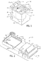
- a washing machine 10 may provide for an outer housing 12 having a control console 14 at the rear edge thereof presenting controls 16 (such as switches and indicator lights) for controlling the operation of the washing machine 10.
- the controls 16 may communicate with an internal controller 18 typically providing for a microprocessor and associated software communicating with various components of the washing machine 10 through a wiring harness 20. Those components may include, for example, the controls 16, valving and pump systems 26, and an agitator motor 28 of types understood in the art.
- the outer housing 12 may provide a hinged lid (not shown for clarity) at the top that may be opened so that a user may access the interior of a spin basket 22, the latter fitting inside a washtub 23.
- An agitator 24 may extend upward from the bottom of the spin basket 22 to agitate the clothes during washing as is generally understood in the art.
- washing-aid dispenser 30 per the present invention may be accessible at a rear of the washtub 23 providing a drawer 32 for containing a wash-aid and removable along axis 34.
- the drawer may provide a front escutcheon 36 attached to a wash-aid reservoir 38, the latter providing a liquid-tight volume for holding wash-aid such as a detergent, fabric softener, bleach, whitener, or the like.
- An access door 40 on the top of the reservoir 38 may open to expose a washing-aid introduction port 42 through which washing-aid may be introduced.
- the drawer 32 slides into a receptacle 44 providing a tray with upstanding sidewalls 46 that receive corresponding sidewalls of the reservoir 38 when the reservoir 38 is inserted into the receptacle 44 along axis 34.
- inwardly extending guide rails 48 generally parallel to the insertion axis 34 may be positioned on each of the sidewalls 46 to slidably fit within corresponding slots 50 in the sidewalls of the reservoir 38. In this way, the height of the reservoir 38 within the receptacle 44 is precisely fixed while allowing a sliding motion.
- a releasable coupling 52 Positioned at a rear wall 53 of the reservoir 38 is a releasable coupling 52 extending generally parallel to axis 34 to mate with a corresponding coupling 54 in a rear wall of the receptacle 44. These two couplings join when the reservoir 38 is fully received within the receptacle 44 to provide a liquid-tight conduit allowing wash-aid from the reservoir 38 to pass into the coupling 54 and from there to be distributed by valving and pump systems 26 to the laundry in the washtub 23 per conventional practice.
- coupling 52 may be self-sealing so as to prevent leakage of wash-aid from the reservoir 38 prior to attachment to the coupling 54.
- a rear wall 51 of the receptacle 44 also holds an optical sensor system 56 exposing two laterally displaced sensor elements 58 that face a rear wall 53 of the reservoir 38 when the reservoir 38 is fully seated in the receptacle 44.
- the height of the reservoir 38 within the receptacle 44 with respect to the sensor system 56 is controlled by one or more of the rails 48, a bottom surface of the receptacle 44, and an engagement of the couplings 52 and 54.
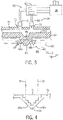
- a rear wall 53 of the reservoir 38 may support a refraction sensitive reflector 60 which provides a varying amount of reflected light depending on the difference between the refractive index of the refraction sensitive reflector 60 and a material with which it is contacting which may be variously a wash-aid 62 or air.
- the refraction sensitive reflector 60 may be integrated into the rear wall 53 of the reservoir 38, for example, by molding the reservoir 38 entirely from a transparent material or by insert molding a transparent material of the refraction sensitive reflector 60 into a separate material of the reservoir 38 or by other means such as adhesive between two separately formed elements.
- the refraction sensitive reflector 60 may likewise be incorporated into containers fabricated by other methods, for example, blow molding, through the use of an adhesively attached optical element either penetrating a wall of the reservoir 38 or attached to the thin transparent portion of the wall, for example, in a prepared pocket in the reservoir 38.
- the refraction sensitive reflector 60 may provide for a right triangular prism 64 of transparent material having a predetermined index of refraction approximately equal to that of a wash-aid 62.
- Two perpendicular planar faces 66a and 66b of the prism 64 may project into the interior volume 68 of the reservoir 38 with an opposed planar base 71 forming an outer surface of the rear wall 53 of the reservoir 38 opposite the planar faces 66.
- the rear wall 51 of the receptacle 44 supports an optical sensor system 56 whose front face 70 abuts an outer surface of the rear wall 53 of the reservoir 38 when the reservoir 38 is fully installed within the receptacle 44.
- the front face 70 of the optical sensor system 56 may provide for horizontally displaced windows or openings 72, a first one communicating with a first light emitter 74 such as an LED within the optical sensor system 56 that projects light along a first axis 76 generally perpendicular with the surface of the base 71 of the prism 64 when the reservoir 38 is fully inserted in the receptacle 44. This projected light passes through an opening 72 to be received through the base 71 of the prism 64.
- the received light is then reflected by internal reflection off of face 66a and toward face 66b whereby, by means of similar internal reflection, it is returned back along axis 78 parallel to axis 76 through a second opening 72.
- a light detector 80 such as a photo transistor or photo diode.
- the light emitter 74 and light detector 80 may attach to other circuitry 82 providing for the necessary amplification, optional modulation, decoding and threshold comparison of electrical signals communicating with the light emitter 74 and light detector 80 as will be described below, for example, to provide a signal to the user of wash-aid exhaustion.
- the circuitry 82 may communicate with the controller 18 to coordinate other aspects of the washing machine 10 such as the presence or absence of wash-aid 62 in the reservoir 38.
- the prism 64 By placing the points of reflection in the prism 64 at a predetermined height, it can be determined if the wash-aid 62 is at or below that height by monitoring the amount of light returned to the light detector 80, for example, against a threshold that may be adjusted over time to accommodate aging in the components.
- the prism 64 provides a way of detecting, through internal reflection, the relative index of refraction of the material in the reservoir 38 enabling a sensor constructed in this fashion to readily distinguish between air and liquid detergent or liquid wash-aid, the latter being primarily water-based.
- a notch 86 may be cut into the base 71 of the prism 64 between the axes 76 and 78 generally removed away from the path of reflected light by removing material from the prism 64.
- This notch 86 reduces the variation of thickness of the plastic wall 53 in the prism area, reducing contraction and deformation and improving the geometrical stability of the prism 64.
- this notch may be substantially smooth so as to provide internal reflection of light within the prism 64 corralling that light along a path more likely to return to the light detector 80. In this way, the effect of scattering an attenuation of light in the material of the wall 53 is compensated accommodating practical limitations in the ability to obtain pure transparency in readily fabricated materials that have suitable index of refraction.
- a stair step channel to be cut through the base 71 into the interior of the prism 64 to reduce the thickness of the prism 64 reducing warpage and cost when the reservoir 38 is constructed of a molded thermoplastic or the like.
- the surfaces of the stair stepping are always perpendicular or parallel to the direction of light propagation through those surfaces to reduce reflection and deflection.
- This approach can also reduce light sinking into the attenuating medium of the prism 64 but places more demands on molding precision and the ability of the thermoplastic material to conform to the necessary sharp corners.
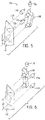
- determining the height of the wash-aid 62 against two or more vertically displaced portions of the prism 64 can allow determination of the height of the wash-aid 62, not simply above or below a single level, but above or below two different height levels.
- Detection of reflection at two heights along the prism 64 can be provided, in principle, by duplicating the light emitter 74 and light detector 80 at two different heights.
- one light emitter 74 or one light detector 80 may be eliminated through the use of a light pipe providing an optical beam splitter/combiner 90 associated with either one or the other of the light detectors 80 (shown in Fig.
- a first and second light emitter 74a and 74b may be vertically displaced behind the front face 70 of the optical sensor system 56 (shown in Fig. 3 ) to project light along respective axes 76a and 76b parallel but separated by a height 92.
- These beams of light may be received by an extended height prism 64 and reflect off of face 66a so that the light beam along axis 76a returns along axis 78a to be received by one entry point of a beam splitter/combiner 90 conducting the light to a light detector 80, and the light along axis 76b returns along axis 78b to be received by a second entry point of beam splitter/combiner 90 to be conducted to the light detector 80.
- first and second light emitters 74a and 74b in time with the detection of the light received at light detector 80, separate measurements may be made of the existence of a high index of refraction wash-aid 62 at the height of axis 76a and the height of axis 76b.
- the beam splitter/combiner 90 may be used in a forward direction and associated with a single light emitter 74 (for example, oriented vertically as is the case with light detector 80 in Fig. 5 ) to provide two simultaneous beams of light separately detected by two light detectors 80a and 80b also vertically displaced by the height 92.
- the invention also contemplates that there may be beam splitters on both emitter and detector. In this case there is no time multiplexing but an analog measure of light feedback. Each time the detergent level covers or uncovers a branch of one of the splitters there will be a variation of light feedback at detector. With two sensing position (a beam splitter with one bifurcation) variations provide for three steps of 100%, 50% and 0% signal transmission. With beam splitters each having four branches, the variations provide for 100-75-50-25-0% signal variations.
- substantially continuous resolution of the height of wash-aid 62 along a height of an extended height prism 64 may be made by using a vertically oriented dispersing light pipe 90a and a vertically oriented collimating light pipe 90b associated, respectively, with a light emitter 74 and light detector 80.
- the dispersing light pipe 90a receives light along a vertical axis and disperses that light horizontally to project toward the prism 64 at multiple heights in the manner of a backlight.
- the dispersing light pipe 90a may provide for multiple internal reflections to distribute light along the length of the dispersing light pipe 90a while having a prismed surface releasing light toward the prism 64 at the various heights.
- the collimating light pipe 90b may receive light from the prism 64 at a variety of heights and collect that light to be collimated to a single light detector 80.
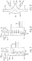
- the refraction sensitive reflector 60 need not be a prism 64 but could be constructed having a curved surface 100 exposed to the volume 68 of the reservoir 38 acting as an internal reflector when not abutting wash-aid 62.
- This curved surface 100 may provides an elliptical focusing mirror, for example, in the shape of a parabola providing a focused transmission of reflected light from a light emitter 74 to a detector 80.
- the outer surface of the reservoir 38 may likewise provide for curved lens forms 102 providing a transition of light into and out of the prism 64 through surfaces of the lens forms having one or two that are substantially perpendicular to the propagation direction of the light to reduce internal reflections on the outer side of the reservoir 38.
- the curved lens forms 102 may provide for standard refractive plano-convex lenses augmenting optical coupling with the light emitter 74 and light detector 80.
- collimating or focusing elements may be also used to provide a more precise determination of the level of the wash-aid 62 by focusing the light on a very small area on the interface between the refraction sensitive reflector 60 and material inside the reservoir 38 or to provide "analog" type sensing in which returned light portion to the amount of the ellipse covered by liquid.
- the optical sensor system 56 can also be enlisted to detect whether the reservoir 38 is in place within the receptacle 44 by applying a threshold to the signals received from sensors 80 that distinguish three cases of: (1) the absence of wash-aid 62 against the surface of the prism 64 such as causes strong internal reflection and a high signal level 104 above a first threshold 105 in the signal received by light detector 80, (2) the presence of wash-aid 62 against the surface of the prism 64 causing a weakened internal reflection and a mid-level signal level 106 below threshold 105 but above a second lower threshold 107, and an absence of the receptacle entirely causing a very low light level 108 to be received from the light detector 80 below the threshold 107.
- a threshold to the signals received from sensors 80 that distinguish three cases of: (1) the absence of wash-aid 62 against the surface of the prism 64 such as causes strong internal reflection and a high signal level 104 above a first threshold 105 in the signal received by light detector 80, (2) the presence of wash-aid 62 against the surface
- Figs. 5, 6 and 11 may dedicate one of the optical paths to a detection of the reservoir 38, for example, by placing a highly reflective material such as a metal foil 110 or the like over the lower portion of the extended prism 64 to provide a reflector whose absence clearly indicates the absence of the reservoir 38.
- a highly reflective material such as a metal foil 110 or the like
Landscapes
- Physics & Mathematics (AREA)
- Electromagnetism (AREA)
- Thermal Sciences (AREA)
- Fluid Mechanics (AREA)
- General Physics & Mathematics (AREA)
- Engineering & Computer Science (AREA)
- Textile Engineering (AREA)
- Measurement Of Levels Of Liquids Or Fluent Solid Materials (AREA)
Claims (13)
- Flüssigkeitspegel-Erfassungssystem für ein Gerät (10), aufweisend:- einen Flüssigkeitsbehälter (38) mit einem Volumen (68), der angepasst ist, um eine Flüssigkeit aufzunehmen, und der einen Flüssigkeitsanschluss beinhaltet;- eine Behälteraufnahme (44), die angepasst ist, um den Flüssigkeitsbehälter (38) lösbar aufzunehmen und die Flüssigkeit zwischen dem Gerät (10) und dem Flüssigkeitsbehälter (38) durch den Flüssigkeitsanschluss zu kommunizieren, wenn der Flüssigkeitsbehälter (38) innerhalb der Behälteraufnahme (44) entlang einer Achse (34) aufgenommen ist;wobei der Flüssigkeitsbehälter (38) ferner ein Fenster (72) beinhaltet, das Licht entlang der Achse (34) empfängt und Licht von einer Innenfläche des Fensters (72) reflektiert, das angepasst ist, um die Flüssigkeit zu kontaktieren; wobei die Behälteraufnahme (44) ferner eine optische Sensoranordnung (56) beinhaltet, die in Bezug auf die Behälteraufnahme (44) befestigt ist, um Licht entlang der Achse (34) in das Fenster (72) zu übertragen und um Licht zu empfangen und zu messen, das entlang der Achse (34) von dem Fenster (72) reflektiert wird,wobei der Flüssigkeitsbehälter (38) ferner eine erste Kupplungshälfte (52) beinhaltet, die an einer Rückwand des Flüssigkeitsbehälters (38) positioniert ist, die konfiguriert ist, um lösbar mit einer zweiten Kupplungshälfte (54) in der Rückwand (51) der Aufnahme verbunden zu werden, die konfiguriert ist, um mit der ersten Kupplungshälfte (52) verbunden zu werden,wobei die Behälteraufnahme (44) den Flüssigkeitsbehälter (38) entlang einer horizontalen Achse (34) aufnimmt und das übertragene Licht und das empfangene und gemessene Licht in einer Richtung, die entlang der Achse (34) ausgerichtet ist, verläuft;wobei die erste Kupplungshälfte (52), die den Flüssigkeitsanschluss aufweist, und die zweite Kupplungshälfte (54) eine flüssigkeitsdichte Leitung bereitstellen, wenn sie miteinander verbunden sind, wenn der Flüssigkeitsbehälter (38) in der Behälteraufnahme (44) aufgenommen ist,wobei die Behälteraufnahme (44) und der Flüssigkeitsbehälter (38) zusammenpassende Eingriffsflächen (48, 50) bereitstellen, die eine Höhe eines vorbestimmten Volumens (68) der Flüssigkeit innerhalb des Flüssigkeitsbehälters (38) in Bezug auf den optischen Sensor positionieren, wenn der Flüssigkeitsbehälter (38) innerhalb der Behälteraufnahme (44) aufgenommen ist.
- Flüssigkeitspegel-Erfassungssystem nach Anspruch 1,
wobei das Fenster (72) ein spritzgegossenes thermoplastisches Material ist. - Flüssigkeitspegel-Erfassungssystem nach Anspruch 1 oder 2, wobei die Innenfläche in Form eines dreieckigen Prismas (64) vorliegt, das erste und zweite benachbarte Flächen (66a, 66b) hat, die die Innenfläche bilden und in das Volumen (68) hineinragen, und wobei das übertragene Licht und das empfangene Licht senkrecht durch eine dritte Fläche (71) des dreieckigen Prismas (64) verlaufen, die durch eine Außenwand der Behälteraufnahme (44) bereitgestellt wird.
- Flüssigkeitspegel-Erfassungssystem nach Anspruch 3,
wobei die dritte Fläche (71) einen Hohlraum (86) beinhaltet, der in der dritten Fläche (71) ausgebildet ist, der sich in ein Volumen (68) des dreieckigen Prismas (64) erstreckt, wobei der Hohlraum (86) zwischen einem Weg des übertragenen Lichts und einem Pfad des empfangenen Lichts positioniert ist. - Flüssigkeitspegel-Erfassungssystem nach Anspruch 4,
wobei der Hohlraum (86) eine im Wesentlichen glatte konkave Fläche ist, die eine interne Reflexion von Licht innerhalb des Prismas (64) bereitstellt. - Flüssigkeitspegel-Erfassungssystem nach Anspruch 4,
wobei der Hohlraum (86) eine Treppenstufenfläche stückweise senkrecht zu Wegen des einfallenden und reflektierten Lichts bereitstellt. - Flüssigkeitspegel-Erfassungssystem nach einem der vorhergehenden Ansprüche,
wobei der Flüssigkeitsbehälter (38) und das Fenster (72) einstückig aus thermoplastischem Material gebildet sind. - Flüssigkeitspegel-Erfassungssystem nach einem der vorhergehenden Ansprüche,
wobei der optische Sensor (56) eine Lichtquelle (74, 74a-74b) aufweist, die einfallendes Licht an ersten und zweiten Positionen des Fensters (72) projiziert, die verschiedenen Höhen der Flüssigkeit entsprechen, und der optische Sensor einen Lichtsensor (80, 80a-80b) beinhaltet, der reflektiertes Licht an der ersten und der zweiten Position empfängt, und wobei der optische Sensor unabhängig eine Änderung in dem reflektierten Licht an der ersten und der zweiten Position erfasst, um anzugeben, ob die Flüssigkeit in Kontakt mit der Innenfläche an der ersten oder der zweiten Position ist. - Flüssigkeitspegel-Erfassungssystem nach Anspruch 8,
ferner aufweisend eine verzweigte Lichtröhre (90), die Enden der Verzweigungen hat, die an der ersten und der zweiten Position positioniert sind, um es einem einzelnen optischen Element des optischen Sensors (56) zu ermöglichen, mit den zwei verschiedenen Positionen zu kommunizieren, wobei das optische Element aus dem optischen Emitter (74) und dem Lichtsensor (80) ausgewählt ist. - Flüssigkeitspegel-Erfassungssystem nach Anspruch 8,
ferner aufweisend erste und zweite kontinuierliche Lichtröhren (90a, 90b), die zumindest dem Lichtsensor (80, 80a-80b) und der Lichtquelle (74, 74a-74b) zugeordnet sind, wobei die Lichtröhren (90a, 90b) zwischen zumindest dem Lichtsensor (80, 80a-80b) und der Lichtquelle (74, 74a-74b) und der Innenfläche kommunizieren, die sich über einen kontinuierlichen Bereich unterschiedlicher Höhen der Flüssigkeit erstrecken, um ein analoges Signal bereitzustellen, das eine Höhe der Flüssigkeit über den kontinuierlichen Bereich angibt. - Flüssigkeitspegel-Erfassungssystem nach einem der Ansprüche 8 bis 10,
wobei die Innenfläche in Form eines konkaven Spiegels (102) vorliegt, der eine Fokussierung von einfallendem Licht von der Lichtquelle (74, 74a-74b) des optischen Sensors nach Reflexion an den Lichtsensor (80, 80a-80b) des optischen Sensors (56) bereitstellt. - Flüssigkeitspegel-Erfassungssystem nach einem der vorhergehenden Ansprüche,
wobei der optische Sensor zumindest zwei Signale bereitstellt, die jeweils eine Waschhilfe (62) in einer ersten vorbestimmten Höhe und den Flüssigkeitsbehälter (38) nicht in der Behälteraufnahme (44) aufgenommen angeben. - Flüssigkeitspegel-Erfassungssystem nach Anspruch 12,
wobei der optische Sensor zumindest drei Signale bereitstellt, die jeweils eine Waschhilfe (62) in einer ersten vorbestimmten Höhe, eine Waschhilfe (62) nicht in einer ersten vorbestimmten Höhe und den Flüssigkeitsbehälter (38) nicht in der Behälteraufnahme (44) aufgenommen angeben.
Priority Applications (1)
| Application Number | Priority Date | Filing Date | Title |
|---|---|---|---|
| EP22165061.7A EP4036534B1 (de) | 2016-12-12 | 2017-11-29 | Optischer füllstandsensor für herausnehmbaren waschhilfebehälter |
Applications Claiming Priority (2)
| Application Number | Priority Date | Filing Date | Title |
|---|---|---|---|
| US201662432776P | 2016-12-12 | 2016-12-12 | |
| PCT/US2017/063731 WO2018111554A1 (en) | 2016-12-12 | 2017-11-29 | Optical level sensor for wash aid removable container |
Related Child Applications (1)
| Application Number | Title | Priority Date | Filing Date |
|---|---|---|---|
| EP22165061.7A Division EP4036534B1 (de) | 2016-12-12 | 2017-11-29 | Optischer füllstandsensor für herausnehmbaren waschhilfebehälter |
Publications (2)
| Publication Number | Publication Date |
|---|---|
| EP3551971A1 EP3551971A1 (de) | 2019-10-16 |
| EP3551971B1 true EP3551971B1 (de) | 2022-04-20 |
Family
ID=60766157
Family Applications (2)
| Application Number | Title | Priority Date | Filing Date |
|---|---|---|---|
| EP22165061.7A Active EP4036534B1 (de) | 2016-12-12 | 2017-11-29 | Optischer füllstandsensor für herausnehmbaren waschhilfebehälter |
| EP17817972.7A Active EP3551971B1 (de) | 2016-12-12 | 2017-11-29 | Optischer füllstandsensor für herausnehmbaren waschhilfebehälter |
Family Applications Before (1)
| Application Number | Title | Priority Date | Filing Date |
|---|---|---|---|
| EP22165061.7A Active EP4036534B1 (de) | 2016-12-12 | 2017-11-29 | Optischer füllstandsensor für herausnehmbaren waschhilfebehälter |
Country Status (4)
| Country | Link |
|---|---|
| US (1) | US10641639B2 (de) |
| EP (2) | EP4036534B1 (de) |
| PL (2) | PL4036534T3 (de) |
| WO (1) | WO2018111554A1 (de) |
Families Citing this family (15)
| Publication number | Priority date | Publication date | Assignee | Title |
|---|---|---|---|---|
| WO2018053217A1 (en) | 2016-09-16 | 2018-03-22 | Fenwal, Inc. | Blood separation systems and methods employing centrifugal and spinning membrane separation techniques |
| US10371559B2 (en) * | 2017-04-17 | 2019-08-06 | The Boeing Company | Differential spectral liquid level sensor |
| JP2021508028A (ja) * | 2018-11-15 | 2021-02-25 | 深▲セン▼市赫▲ジ▼科技有限公司HIZERO Technologies Co.,Ltd. | 液面検出システム及び液面検出方法 |
| EP3705147B1 (de) | 2019-03-05 | 2024-11-06 | Fenwal, Inc. | Sammlung, genombearbeitung und waschen von t-zell-lymphozyten |
| EP4483917A3 (de) | 2019-03-05 | 2025-03-19 | Fenwal, Inc. | Sammeln von mononuklearen zellen und peripheren blutstammzellen |
| EP4238595A3 (de) | 2019-05-23 | 2023-11-29 | Fenwal, Inc. | Einstellung der zielgrenzflächenposition zwischen getrennten fluidkomponenten in einer zentrifuge |
| EP4238596B1 (de) | 2019-05-23 | 2025-04-02 | Fenwal, Inc. | Zentrifugale trennung und sammlung von roten blutkörperchen oder von erythrozyten und plasma |
| US11957828B2 (en) | 2019-09-16 | 2024-04-16 | Fenwal, Inc. | Dynamic adjustment of algorithms for separation and collection of blood components |
| DE102019128857A1 (de) * | 2019-10-25 | 2021-04-29 | Miele & Cie. Kg | Wäschebehandlungsmaschine zur Behandlung von Wäsche |
| EP3834858A1 (de) | 2019-12-12 | 2021-06-16 | Fenwal, Inc. | Systeme, die alternative ansätze zum therapeutischen austausch roter blutkörperchen und/oder zum therapeutischen plasmaaustausch ermöglichen |
| CN115666752A (zh) * | 2020-06-04 | 2023-01-31 | 默克专利股份有限公司 | 用于监测和调节生物容器中的内容物高度的系统和方法 |
| JP7466077B2 (ja) * | 2020-10-01 | 2024-04-12 | パナソニックIpマネジメント株式会社 | 洗濯機 |
| JP2022059342A (ja) * | 2020-10-01 | 2022-04-13 | パナソニックIpマネジメント株式会社 | 洗濯機 |
| WO2022070754A1 (ja) * | 2020-10-01 | 2022-04-07 | パナソニックIpマネジメント株式会社 | 洗濯機 |
| CN116088066B (zh) * | 2023-01-28 | 2025-04-22 | 云鲸智能(深圳)有限公司 | 自动检测方法和用液设备 |
Citations (3)
| Publication number | Priority date | Publication date | Assignee | Title |
|---|---|---|---|---|
| DE102009002694A1 (de) * | 2008-07-15 | 2010-02-04 | Henkel Ag & Co. Kgaa | Dosiersystem |
| DE102010028483A1 (de) * | 2010-05-03 | 2011-11-03 | Henkel Ag & Co. Kgaa | Dosiersystem zur Freisetzung von bleichmittelhaltigen Zubereitungen während eines Waschprogramms einer Waschmaschine |
| US20120247158A1 (en) * | 2009-10-12 | 2012-10-04 | Alexander Ditze | Door for the fluid-tight closure of a laundry loading or removal opening of a laundry treatment appliance, in particular of a washing machine and/or clothes dryer |
Family Cites Families (11)
| Publication number | Priority date | Publication date | Assignee | Title |
|---|---|---|---|---|
| DE3240047A1 (de) * | 1982-10-28 | 1984-05-03 | Bosch-Siemens Hausgeräte GmbH, 7000 Stuttgart | Vorrichtung in wasch- oder spuelmaschinen |
| FR2544877B1 (fr) * | 1983-04-22 | 1986-07-04 | Electricite De France | Sonde optique |
| JP3221210B2 (ja) * | 1994-02-07 | 2001-10-22 | 富士ゼロックス株式会社 | インクタンク |
| JPH10323993A (ja) * | 1997-02-19 | 1998-12-08 | Canon Inc | 検出システム、該検出システムを用いる液体吐出記録装置と液体収納容器、及び、光量変化受光システム |
| JP2004198376A (ja) * | 2002-12-20 | 2004-07-15 | Yazaki Corp | 液面検知装置 |
| ITTO20050856A1 (it) * | 2005-12-06 | 2007-06-07 | Eltek Spa | Componente per elettrodomestico, in particolare per lavastoviglie, e pozzetto per elettrodomestico, in particolare per lavastoviglie, che lo utilizza |
| DE102006043973A1 (de) * | 2006-09-19 | 2008-03-27 | BSH Bosch und Siemens Hausgeräte GmbH | Wasserführendes Haushaltsgerät mit Reinigungsmitteldosiersystem |
| IT1398785B1 (it) * | 2009-08-04 | 2013-03-18 | Illinois Tool Works | Sensore ottico per rilevare il livello di liquido in un contenitore, in particolare per un contenitore asportabile per un elettrodomestico e lente e metodo associati |
| CN202403767U (zh) * | 2012-01-13 | 2012-08-29 | 柳州 | 光电式液位传感器 |
| ITTO20120598A1 (it) * | 2012-07-06 | 2014-01-07 | Illinois Tool Works | Dispositivo di riscaldamento per elettrodomestici con sensore ottico di livello di liquido |
| CN202793526U (zh) * | 2012-08-15 | 2013-03-13 | 柳州 | 液位传感装置以及具有水箱的电器设备 |
-
2017
- 2017-11-29 PL PL22165061.7T patent/PL4036534T3/pl unknown
- 2017-11-29 WO PCT/US2017/063731 patent/WO2018111554A1/en not_active Ceased
- 2017-11-29 EP EP22165061.7A patent/EP4036534B1/de active Active
- 2017-11-29 EP EP17817972.7A patent/EP3551971B1/de active Active
- 2017-11-29 PL PL17817972.7T patent/PL3551971T3/pl unknown
- 2017-12-01 US US15/829,607 patent/US10641639B2/en active Active
Patent Citations (3)
| Publication number | Priority date | Publication date | Assignee | Title |
|---|---|---|---|---|
| DE102009002694A1 (de) * | 2008-07-15 | 2010-02-04 | Henkel Ag & Co. Kgaa | Dosiersystem |
| US20120247158A1 (en) * | 2009-10-12 | 2012-10-04 | Alexander Ditze | Door for the fluid-tight closure of a laundry loading or removal opening of a laundry treatment appliance, in particular of a washing machine and/or clothes dryer |
| DE102010028483A1 (de) * | 2010-05-03 | 2011-11-03 | Henkel Ag & Co. Kgaa | Dosiersystem zur Freisetzung von bleichmittelhaltigen Zubereitungen während eines Waschprogramms einer Waschmaschine |
Also Published As
| Publication number | Publication date |
|---|---|
| EP4036534B1 (de) | 2024-01-31 |
| EP3551971A1 (de) | 2019-10-16 |
| PL4036534T3 (pl) | 2024-06-24 |
| WO2018111554A1 (en) | 2018-06-21 |
| US10641639B2 (en) | 2020-05-05 |
| PL3551971T3 (pl) | 2022-08-16 |
| US20180164141A1 (en) | 2018-06-14 |
| EP4036534A1 (de) | 2022-08-03 |
Similar Documents
| Publication | Publication Date | Title |
|---|---|---|
| EP3551971B1 (de) | Optischer füllstandsensor für herausnehmbaren waschhilfebehälter | |
| EP2228633B1 (de) | Optischer Füllstandssensor für eine Getränkemaschine | |
| KR101767163B1 (ko) | 용기, 특히 가전 기기를 위한 탈착가능한 용기 내의 액체 레벨을 검출하기 위한 광학 센서, 및 관련 렌즈와 방법 | |
| US8122743B2 (en) | Automatically controlled washing machine | |
| JP6236442B2 (ja) | 飲料調製機における自動検出のためのシステム | |
| EP0777111B1 (de) | Vorrichtung und Verfahren zur Flüssigkeitsstandsmessung | |
| RU2451120C2 (ru) | Стиральная машина с визуальным индикатором уровня моющего средства | |
| KR20170030525A (ko) | 끓여낸 음료를 준비하기 위한 장치, 및 캡슐 및 캡슐 시스템 및 끓여낸 음료를 준비하기 위한 방법 | |
| CA2520058A1 (en) | Dishwasher with at least one dispenser intended for the provision of a detergent additive | |
| EP2411773B1 (de) | Verfahren zur detektion des stands einer flüssigkeit, eines gels oder eines pulvers in einem behälter | |
| EP3433411B1 (de) | Haushaltswaschmaschine | |
| US10799058B2 (en) | System for automated detection in beverage dispensing machines | |
| EP3708059A1 (de) | System und verfahren zur abgabe einer flüssigkeit, insbesondere in einem haushaltsgerät | |
| CN223189439U (zh) | 自动投放装置和衣物处理设备 | |
| CN114761636B (zh) | 容器及使用其的洗衣机 | |
| JP2024011181A (ja) | 洗浄装置 | |
| HK1148346A (en) | Optical level detector for a beverage machine | |
| JPH05245045A (ja) | 茶葉切れ検出装置 | |
| ITTO20090606A1 (it) | Sensore ottico per rilevare il livello di liquido in un contenitore, in particolare per un contenitore asportabile per un elettrodomestico e lente e metodo associati | |
| ITTO20120031U1 (it) | Sensore ottico per rilevare il livello di liquido in un contenitore, in particolare per un contenitore asportabile per un elettrodomestico e lente e metodo associati |
Legal Events
| Date | Code | Title | Description |
|---|---|---|---|
| STAA | Information on the status of an ep patent application or granted ep patent |
Free format text: STATUS: UNKNOWN |
|
| STAA | Information on the status of an ep patent application or granted ep patent |
Free format text: STATUS: THE INTERNATIONAL PUBLICATION HAS BEEN MADE |
|
| PUAI | Public reference made under article 153(3) epc to a published international application that has entered the european phase |
Free format text: ORIGINAL CODE: 0009012 |
|
| STAA | Information on the status of an ep patent application or granted ep patent |
Free format text: STATUS: REQUEST FOR EXAMINATION WAS MADE |
|
| 17P | Request for examination filed |
Effective date: 20190710 |
|
| AK | Designated contracting states |
Kind code of ref document: A1 Designated state(s): AL AT BE BG CH CY CZ DE DK EE ES FI FR GB GR HR HU IE IS IT LI LT LU LV MC MK MT NL NO PL PT RO RS SE SI SK SM TR |
|
| AX | Request for extension of the european patent |
Extension state: BA ME |
|
| DAV | Request for validation of the european patent (deleted) | ||
| DAX | Request for extension of the european patent (deleted) | ||
| STAA | Information on the status of an ep patent application or granted ep patent |
Free format text: STATUS: EXAMINATION IS IN PROGRESS |
|
| 17Q | First examination report despatched |
Effective date: 20200722 |
|
| REG | Reference to a national code |
Ref country code: DE Ref legal event code: R079 Ref document number: 602017056316 Country of ref document: DE Free format text: PREVIOUS MAIN CLASS: G01F0023292000 Ipc: D06F0033370000 |
|
| RIC1 | Information provided on ipc code assigned before grant |
Ipc: D06F 39/02 20060101ALI20210922BHEP Ipc: G01F 23/292 20060101ALI20210922BHEP Ipc: D06F 33/37 20200101AFI20210922BHEP |
|
| GRAP | Despatch of communication of intention to grant a patent |
Free format text: ORIGINAL CODE: EPIDOSNIGR1 |
|
| STAA | Information on the status of an ep patent application or granted ep patent |
Free format text: STATUS: GRANT OF PATENT IS INTENDED |
|
| INTG | Intention to grant announced |
Effective date: 20211104 |
|
| GRAS | Grant fee paid |
Free format text: ORIGINAL CODE: EPIDOSNIGR3 |
|
| GRAA | (expected) grant |
Free format text: ORIGINAL CODE: 0009210 |
|
| STAA | Information on the status of an ep patent application or granted ep patent |
Free format text: STATUS: THE PATENT HAS BEEN GRANTED |
|
| AK | Designated contracting states |
Kind code of ref document: B1 Designated state(s): AL AT BE BG CH CY CZ DE DK EE ES FI FR GB GR HR HU IE IS IT LI LT LU LV MC MK MT NL NO PL PT RO RS SE SI SK SM TR |
|
| REG | Reference to a national code |
Ref country code: GB Ref legal event code: FG4D |
|
| REG | Reference to a national code |
Ref country code: CH Ref legal event code: EP |
|
| REG | Reference to a national code |
Ref country code: IE Ref legal event code: FG4D |
|
| REG | Reference to a national code |
Ref country code: DE Ref legal event code: R096 Ref document number: 602017056316 Country of ref document: DE |
|
| REG | Reference to a national code |
Ref country code: AT Ref legal event code: REF Ref document number: 1485215 Country of ref document: AT Kind code of ref document: T Effective date: 20220515 |
|
| REG | Reference to a national code |
Ref country code: LT Ref legal event code: MG9D |
|
| REG | Reference to a national code |
Ref country code: NL Ref legal event code: MP Effective date: 20220420 |
|
| REG | Reference to a national code |
Ref country code: AT Ref legal event code: MK05 Ref document number: 1485215 Country of ref document: AT Kind code of ref document: T Effective date: 20220420 |
|
| PG25 | Lapsed in a contracting state [announced via postgrant information from national office to epo] |
Ref country code: NL Free format text: LAPSE BECAUSE OF FAILURE TO SUBMIT A TRANSLATION OF THE DESCRIPTION OR TO PAY THE FEE WITHIN THE PRESCRIBED TIME-LIMIT Effective date: 20220420 |
|
| PG25 | Lapsed in a contracting state [announced via postgrant information from national office to epo] |
Ref country code: SE Free format text: LAPSE BECAUSE OF FAILURE TO SUBMIT A TRANSLATION OF THE DESCRIPTION OR TO PAY THE FEE WITHIN THE PRESCRIBED TIME-LIMIT Effective date: 20220420 Ref country code: PT Free format text: LAPSE BECAUSE OF FAILURE TO SUBMIT A TRANSLATION OF THE DESCRIPTION OR TO PAY THE FEE WITHIN THE PRESCRIBED TIME-LIMIT Effective date: 20220822 Ref country code: NO Free format text: LAPSE BECAUSE OF FAILURE TO SUBMIT A TRANSLATION OF THE DESCRIPTION OR TO PAY THE FEE WITHIN THE PRESCRIBED TIME-LIMIT Effective date: 20220720 Ref country code: LT Free format text: LAPSE BECAUSE OF FAILURE TO SUBMIT A TRANSLATION OF THE DESCRIPTION OR TO PAY THE FEE WITHIN THE PRESCRIBED TIME-LIMIT Effective date: 20220420 Ref country code: HR Free format text: LAPSE BECAUSE OF FAILURE TO SUBMIT A TRANSLATION OF THE DESCRIPTION OR TO PAY THE FEE WITHIN THE PRESCRIBED TIME-LIMIT Effective date: 20220420 Ref country code: GR Free format text: LAPSE BECAUSE OF FAILURE TO SUBMIT A TRANSLATION OF THE DESCRIPTION OR TO PAY THE FEE WITHIN THE PRESCRIBED TIME-LIMIT Effective date: 20220721 Ref country code: FI Free format text: LAPSE BECAUSE OF FAILURE TO SUBMIT A TRANSLATION OF THE DESCRIPTION OR TO PAY THE FEE WITHIN THE PRESCRIBED TIME-LIMIT Effective date: 20220420 Ref country code: ES Free format text: LAPSE BECAUSE OF FAILURE TO SUBMIT A TRANSLATION OF THE DESCRIPTION OR TO PAY THE FEE WITHIN THE PRESCRIBED TIME-LIMIT Effective date: 20220420 Ref country code: BG Free format text: LAPSE BECAUSE OF FAILURE TO SUBMIT A TRANSLATION OF THE DESCRIPTION OR TO PAY THE FEE WITHIN THE PRESCRIBED TIME-LIMIT Effective date: 20220720 Ref country code: AT Free format text: LAPSE BECAUSE OF FAILURE TO SUBMIT A TRANSLATION OF THE DESCRIPTION OR TO PAY THE FEE WITHIN THE PRESCRIBED TIME-LIMIT Effective date: 20220420 |
|
| PG25 | Lapsed in a contracting state [announced via postgrant information from national office to epo] |
Ref country code: RS Free format text: LAPSE BECAUSE OF FAILURE TO SUBMIT A TRANSLATION OF THE DESCRIPTION OR TO PAY THE FEE WITHIN THE PRESCRIBED TIME-LIMIT Effective date: 20220420 Ref country code: LV Free format text: LAPSE BECAUSE OF FAILURE TO SUBMIT A TRANSLATION OF THE DESCRIPTION OR TO PAY THE FEE WITHIN THE PRESCRIBED TIME-LIMIT Effective date: 20220420 Ref country code: IS Free format text: LAPSE BECAUSE OF FAILURE TO SUBMIT A TRANSLATION OF THE DESCRIPTION OR TO PAY THE FEE WITHIN THE PRESCRIBED TIME-LIMIT Effective date: 20220820 |
|
| REG | Reference to a national code |
Ref country code: DE Ref legal event code: R097 Ref document number: 602017056316 Country of ref document: DE |
|
| PG25 | Lapsed in a contracting state [announced via postgrant information from national office to epo] |
Ref country code: SM Free format text: LAPSE BECAUSE OF FAILURE TO SUBMIT A TRANSLATION OF THE DESCRIPTION OR TO PAY THE FEE WITHIN THE PRESCRIBED TIME-LIMIT Effective date: 20220420 Ref country code: SK Free format text: LAPSE BECAUSE OF FAILURE TO SUBMIT A TRANSLATION OF THE DESCRIPTION OR TO PAY THE FEE WITHIN THE PRESCRIBED TIME-LIMIT Effective date: 20220420 Ref country code: RO Free format text: LAPSE BECAUSE OF FAILURE TO SUBMIT A TRANSLATION OF THE DESCRIPTION OR TO PAY THE FEE WITHIN THE PRESCRIBED TIME-LIMIT Effective date: 20220420 Ref country code: EE Free format text: LAPSE BECAUSE OF FAILURE TO SUBMIT A TRANSLATION OF THE DESCRIPTION OR TO PAY THE FEE WITHIN THE PRESCRIBED TIME-LIMIT Effective date: 20220420 Ref country code: DK Free format text: LAPSE BECAUSE OF FAILURE TO SUBMIT A TRANSLATION OF THE DESCRIPTION OR TO PAY THE FEE WITHIN THE PRESCRIBED TIME-LIMIT Effective date: 20220420 Ref country code: CZ Free format text: LAPSE BECAUSE OF FAILURE TO SUBMIT A TRANSLATION OF THE DESCRIPTION OR TO PAY THE FEE WITHIN THE PRESCRIBED TIME-LIMIT Effective date: 20220420 |
|
| PLBE | No opposition filed within time limit |
Free format text: ORIGINAL CODE: 0009261 |
|
| STAA | Information on the status of an ep patent application or granted ep patent |
Free format text: STATUS: NO OPPOSITION FILED WITHIN TIME LIMIT |
|
| 26N | No opposition filed |
Effective date: 20230123 |
|
| PG25 | Lapsed in a contracting state [announced via postgrant information from national office to epo] |
Ref country code: AL Free format text: LAPSE BECAUSE OF FAILURE TO SUBMIT A TRANSLATION OF THE DESCRIPTION OR TO PAY THE FEE WITHIN THE PRESCRIBED TIME-LIMIT Effective date: 20220420 |
|
| PG25 | Lapsed in a contracting state [announced via postgrant information from national office to epo] |
Ref country code: SI Free format text: LAPSE BECAUSE OF FAILURE TO SUBMIT A TRANSLATION OF THE DESCRIPTION OR TO PAY THE FEE WITHIN THE PRESCRIBED TIME-LIMIT Effective date: 20220420 |
|
| PG25 | Lapsed in a contracting state [announced via postgrant information from national office to epo] |
Ref country code: MC Free format text: LAPSE BECAUSE OF FAILURE TO SUBMIT A TRANSLATION OF THE DESCRIPTION OR TO PAY THE FEE WITHIN THE PRESCRIBED TIME-LIMIT Effective date: 20220420 |
|
| REG | Reference to a national code |
Ref country code: CH Ref legal event code: PL |
|
| P01 | Opt-out of the competence of the unified patent court (upc) registered |
Effective date: 20230606 |
|
| GBPC | Gb: european patent ceased through non-payment of renewal fee |
Effective date: 20221129 |
|
| REG | Reference to a national code |
Ref country code: BE Ref legal event code: MM Effective date: 20221130 |
|
| PG25 | Lapsed in a contracting state [announced via postgrant information from national office to epo] |
Ref country code: LI Free format text: LAPSE BECAUSE OF NON-PAYMENT OF DUE FEES Effective date: 20221130 Ref country code: CH Free format text: LAPSE BECAUSE OF NON-PAYMENT OF DUE FEES Effective date: 20221130 |
|
| PG25 | Lapsed in a contracting state [announced via postgrant information from national office to epo] |
Ref country code: LU Free format text: LAPSE BECAUSE OF NON-PAYMENT OF DUE FEES Effective date: 20221129 |
|
| PG25 | Lapsed in a contracting state [announced via postgrant information from national office to epo] |
Ref country code: IE Free format text: LAPSE BECAUSE OF NON-PAYMENT OF DUE FEES Effective date: 20221129 Ref country code: GB Free format text: LAPSE BECAUSE OF NON-PAYMENT OF DUE FEES Effective date: 20221129 |
|
| PG25 | Lapsed in a contracting state [announced via postgrant information from national office to epo] |
Ref country code: FR Free format text: LAPSE BECAUSE OF NON-PAYMENT OF DUE FEES Effective date: 20221130 Ref country code: BE Free format text: LAPSE BECAUSE OF NON-PAYMENT OF DUE FEES Effective date: 20221130 |
|
| PG25 | Lapsed in a contracting state [announced via postgrant information from national office to epo] |
Ref country code: HU Free format text: LAPSE BECAUSE OF FAILURE TO SUBMIT A TRANSLATION OF THE DESCRIPTION OR TO PAY THE FEE WITHIN THE PRESCRIBED TIME-LIMIT; INVALID AB INITIO Effective date: 20171129 |
|
| PG25 | Lapsed in a contracting state [announced via postgrant information from national office to epo] |
Ref country code: CY Free format text: LAPSE BECAUSE OF FAILURE TO SUBMIT A TRANSLATION OF THE DESCRIPTION OR TO PAY THE FEE WITHIN THE PRESCRIBED TIME-LIMIT Effective date: 20220420 |
|
| PG25 | Lapsed in a contracting state [announced via postgrant information from national office to epo] |
Ref country code: MK Free format text: LAPSE BECAUSE OF FAILURE TO SUBMIT A TRANSLATION OF THE DESCRIPTION OR TO PAY THE FEE WITHIN THE PRESCRIBED TIME-LIMIT Effective date: 20220420 |
|
| PG25 | Lapsed in a contracting state [announced via postgrant information from national office to epo] |
Ref country code: MT Free format text: LAPSE BECAUSE OF FAILURE TO SUBMIT A TRANSLATION OF THE DESCRIPTION OR TO PAY THE FEE WITHIN THE PRESCRIBED TIME-LIMIT Effective date: 20220420 |
|
| PG25 | Lapsed in a contracting state [announced via postgrant information from national office to epo] |
Ref country code: BG Free format text: LAPSE BECAUSE OF FAILURE TO SUBMIT A TRANSLATION OF THE DESCRIPTION OR TO PAY THE FEE WITHIN THE PRESCRIBED TIME-LIMIT Effective date: 20220420 |
|
| PG25 | Lapsed in a contracting state [announced via postgrant information from national office to epo] |
Ref country code: BG Free format text: LAPSE BECAUSE OF FAILURE TO SUBMIT A TRANSLATION OF THE DESCRIPTION OR TO PAY THE FEE WITHIN THE PRESCRIBED TIME-LIMIT Effective date: 20220420 |
|
| PGFP | Annual fee paid to national office [announced via postgrant information from national office to epo] |
Ref country code: PL Payment date: 20241128 Year of fee payment: 8 |
|
| PGFP | Annual fee paid to national office [announced via postgrant information from national office to epo] |
Ref country code: TR Payment date: 20241111 Year of fee payment: 8 |
|
| PGFP | Annual fee paid to national office [announced via postgrant information from national office to epo] |
Ref country code: DE Payment date: 20251128 Year of fee payment: 9 |
|
| PGFP | Annual fee paid to national office [announced via postgrant information from national office to epo] |
Ref country code: IT Payment date: 20251119 Year of fee payment: 9 |