EP3551948B1 - Vanne d'expansion - Google Patents
Vanne d'expansion Download PDFInfo
- Publication number
- EP3551948B1 EP3551948B1 EP17829608.3A EP17829608A EP3551948B1 EP 3551948 B1 EP3551948 B1 EP 3551948B1 EP 17829608 A EP17829608 A EP 17829608A EP 3551948 B1 EP3551948 B1 EP 3551948B1
- Authority
- EP
- European Patent Office
- Prior art keywords
- channel structure
- fluid
- valve element
- valve
- flow
- Prior art date
- Legal status (The legal status is an assumption and is not a legal conclusion. Google has not performed a legal analysis and makes no representation as to the accuracy of the status listed.)
- Active
Links
Images











Classifications
-
- F—MECHANICAL ENGINEERING; LIGHTING; HEATING; WEAPONS; BLASTING
- F16—ENGINEERING ELEMENTS AND UNITS; GENERAL MEASURES FOR PRODUCING AND MAINTAINING EFFECTIVE FUNCTIONING OF MACHINES OR INSTALLATIONS; THERMAL INSULATION IN GENERAL
- F16K—VALVES; TAPS; COCKS; ACTUATING-FLOATS; DEVICES FOR VENTING OR AERATING
- F16K11/00—Multiple-way valves, e.g. mixing valves; Pipe fittings incorporating such valves
-
- F—MECHANICAL ENGINEERING; LIGHTING; HEATING; WEAPONS; BLASTING
- F16—ENGINEERING ELEMENTS AND UNITS; GENERAL MEASURES FOR PRODUCING AND MAINTAINING EFFECTIVE FUNCTIONING OF MACHINES OR INSTALLATIONS; THERMAL INSULATION IN GENERAL
- F16K—VALVES; TAPS; COCKS; ACTUATING-FLOATS; DEVICES FOR VENTING OR AERATING
- F16K11/00—Multiple-way valves, e.g. mixing valves; Pipe fittings incorporating such valves
- F16K11/02—Multiple-way valves, e.g. mixing valves; Pipe fittings incorporating such valves with all movable sealing faces moving as one unit
- F16K11/06—Multiple-way valves, e.g. mixing valves; Pipe fittings incorporating such valves with all movable sealing faces moving as one unit comprising only sliding valves, i.e. sliding closure elements
- F16K11/072—Multiple-way valves, e.g. mixing valves; Pipe fittings incorporating such valves with all movable sealing faces moving as one unit comprising only sliding valves, i.e. sliding closure elements with pivoted closure members
- F16K11/074—Multiple-way valves, e.g. mixing valves; Pipe fittings incorporating such valves with all movable sealing faces moving as one unit comprising only sliding valves, i.e. sliding closure elements with pivoted closure members with flat sealing faces
-
- F—MECHANICAL ENGINEERING; LIGHTING; HEATING; WEAPONS; BLASTING
- F25—REFRIGERATION OR COOLING; COMBINED HEATING AND REFRIGERATION SYSTEMS; HEAT PUMP SYSTEMS; MANUFACTURE OR STORAGE OF ICE; LIQUEFACTION SOLIDIFICATION OF GASES
- F25B—REFRIGERATION MACHINES, PLANTS OR SYSTEMS; COMBINED HEATING AND REFRIGERATION SYSTEMS; HEAT PUMP SYSTEMS
- F25B41/00—Fluid-circulation arrangements
- F25B41/30—Expansion means; Dispositions thereof
- F25B41/31—Expansion valves
- F25B41/34—Expansion valves with the valve member being actuated by electric means, e.g. by piezoelectric actuators
- F25B41/35—Expansion valves with the valve member being actuated by electric means, e.g. by piezoelectric actuators by rotary motors, e.g. by stepping motors
-
- F—MECHANICAL ENGINEERING; LIGHTING; HEATING; WEAPONS; BLASTING
- F16—ENGINEERING ELEMENTS AND UNITS; GENERAL MEASURES FOR PRODUCING AND MAINTAINING EFFECTIVE FUNCTIONING OF MACHINES OR INSTALLATIONS; THERMAL INSULATION IN GENERAL
- F16K—VALVES; TAPS; COCKS; ACTUATING-FLOATS; DEVICES FOR VENTING OR AERATING
- F16K99/00—Subject matter not provided for in other groups of this subclass
- F16K99/0001—Microvalves
- F16K99/0003—Constructional types of microvalves; Details of the cutting-off member
- F16K99/0013—Rotary valves
-
- F—MECHANICAL ENGINEERING; LIGHTING; HEATING; WEAPONS; BLASTING
- F25—REFRIGERATION OR COOLING; COMBINED HEATING AND REFRIGERATION SYSTEMS; HEAT PUMP SYSTEMS; MANUFACTURE OR STORAGE OF ICE; LIQUEFACTION SOLIDIFICATION OF GASES
- F25B—REFRIGERATION MACHINES, PLANTS OR SYSTEMS; COMBINED HEATING AND REFRIGERATION SYSTEMS; HEAT PUMP SYSTEMS
- F25B2341/00—Details of ejectors not being used as compression device; Details of flow restrictors or expansion valves
- F25B2341/06—Details of flow restrictors or expansion valves
-
- Y—GENERAL TAGGING OF NEW TECHNOLOGICAL DEVELOPMENTS; GENERAL TAGGING OF CROSS-SECTIONAL TECHNOLOGIES SPANNING OVER SEVERAL SECTIONS OF THE IPC; TECHNICAL SUBJECTS COVERED BY FORMER USPC CROSS-REFERENCE ART COLLECTIONS [XRACs] AND DIGESTS
- Y02—TECHNOLOGIES OR APPLICATIONS FOR MITIGATION OR ADAPTATION AGAINST CLIMATE CHANGE
- Y02B—CLIMATE CHANGE MITIGATION TECHNOLOGIES RELATED TO BUILDINGS, e.g. HOUSING, HOUSE APPLIANCES OR RELATED END-USER APPLICATIONS
- Y02B30/00—Energy efficient heating, ventilation or air conditioning [HVAC]
- Y02B30/70—Efficient control or regulation technologies, e.g. for control of refrigerant flow, motor or heating
Definitions
- the invention relates to expansion valves for reducing a pressure of a fluid flowing through the expansion valve along a fluid flow path.
- Expansion valves can be used in refrigeration cycles, for example.
- Figure 8 shows such a refrigeration cycle 81 as is known in the prior art.
- the refrigeration circuit 81 has a condenser 82 and an evaporator 83. Between the condenser 82 and the evaporator 83 there is a local constriction 84a, 84b of the flow cross-section, which leads to a reduction in the fluid pressure and causes an increase in volume or expansion of the fluid flowing through.
- This local constriction 84a, 84b is functionally referred to as a throttle or expansion valve.
- a piece of tube with a very small inside diameter acts as an unregulated, non-adjustable expansion element, which is then typically referred to as a throttle capillary 84b.
- Inexpensive throttle capillaries are preferred for systems with low cooling capacity, such as household fridge-freezers.
- controllable expansion valves 84a are continuously variable valves which allow the fluid flowing through to be adjusted. These are preferred for systems with a higher cooling capacity.
- a solution is therefore not to use a continuously adjustable valve but a switching valve that is then completely open or closed at times, i.e. is operated in the sense of a pulse width modulation.
- this approach is rated as not so favorable in terms of energy and system behavior.
- An expansion valve for small cooling capacities can also be called a micro-expansion valve.
- the DE 10 2010 042 265 A1 describes a multi-way valve for switching between two channels.
- rigid perforated diaphragms or adjustable slit diaphragms are used as throttles, which is why this form of valve is also referred to as diaphragm valve.
- the DE 10 2010 042265 A1 a valve for reducing a pressure of a fluid flowing through the expansion valve along a fluid flow path, the valve comprising: at least one fluid inlet and at least one fluid outlet, a first valve element with at least a first channel structure, a second valve element with at least a second channel structure and a third channel structure , wherein the first valve element and the second valve element are movable relative to one another, wherein in a first position of the valve elements the first channel structure and the second channel structure are aligned with one another and form a first fluid flow path with a first flow resistance between the fluid inlet and the fluid outlet, and wherein in one second position of the valve elements, the first channel structure and the third channel structure are aligned with one another and a second fluid flow path with a second flow resistance different from the first flow resistance and form between the fluid inlet and the fluid outlet.
- channels through which the fluid flows are known.
- the slowing down and thus the expansion of the fluid is mainly due to eddy currents caused at the edge of the diaphragm.
- An expansion valve with channels is for example in the DE 31 08 051 A1 suggested.
- An expansion valve that can be switched in discrete switching stages is described here.
- Several disks are placed one on top of the other, with radially extending channels being formed between the disks through which the fluid can flow.
- In the middle of the disks there is a piston which can be moved in the axial direction to allow the fluid to flow through the individual channels.
- this expansion valve has a complicated structure and a large axial overall height. For devices with low cooling capacities, at where there is usually only a very small amount of space available, this expansion valve is therefore less suitable.
- the fluid flowing through the expansion valve contains particles. These particles can clog the expansion valve or individual channels of the expansion valve, which in turn can lead to a (partial) failure of the expansion valve.
- the EP 3 124 837 A1 therefore suggests providing a circumferential groove with several shielding parts in the form of projections on a valve body.
- the production of the many individual projections is complex, however. Apart from this, it was already recognized in the publication itself that certain types of soiling, such as hair, for example, cannot be held back sufficiently well by these shielding parts. It is an object of the present invention to improve expansion valves with regard to the problems mentioned above.
- the expansion valve according to the invention is designed to reduce a pressure of a fluid flowing through the expansion valve along a fluid flow path.
- the expansion valve has, inter alia, at least one fluid inlet through which the fluid can flow into the expansion valve, and at least one fluid outlet through which the fluid can flow out of the expansion valve.
- the expansion valve also has a first valve element with at least one first channel structure.
- the expansion valve has a second valve element with at least a second channel structure and a third channel structure.
- the first valve element and the second valve element are movable relative to one another, wherein in a first position of the valve elements the first channel structure and the second channel structure are aligned with one another and form a first fluid flow path with a first flow resistance between the fluid inlet and the fluid outlet. In a second position of the valve elements, the first channel structure and the third channel structure are aligned with one another and form a second fluid flow path with a second flow resistance, different from the first flow resistance, between the fluid inlet and the fluid outlet.
- a flow resistance can, for example, consist of a length of the flow-through channel structure, the cross-section of the flow-through channel structure that is not necessarily uniform along the length of the flow-through, a change in the flow-through cross-section or the channel course, a geometric cross-sectional shape, a roughness of the surface of the walls of the flow-through channel structure, or Combination of these parameters result.
- the different flow resistances throttle the flow of the fluid to different degrees.
- the throttling effect can be adjusted by varying the aforementioned parameters.
- the expansion valve according to the invention can bring about a complete throttling in one switching position, so that the flow of the fluid is almost completely blocked from the fluid inlet to the fluid outlet.
- the expansion valve according to the invention cannot, for example, have any significant throttling in another switching position, so that the fluid can flow almost unimpeded from the fluid inlet to the fluid outlet.
- the expansion valve can provide any desired throttle stage, ie between complete blocking and complete flow-through. As mentioned above, this is possible by varying the channel structure parameters.
- the amount of pressure drop is determined by the throttle stages, ie by the flow resistance, of the individual channel structures.
- the invention thus creates the integration of different flow resistances together with a switchable distributor within a single expansion valve. This can considerably reduce the installation space required compared to distributor circuits with separate chokes or capillaries.
- the requirements placed on the required precision of the drive are significantly lower, which in turn significantly reduces the manufacturing costs.
- channel structures are described on the basis of two exemplary channel structures, namely a first channel structure 22a, 22b and a second channel structure 23a, 23b.
- Each channel structure 22a, 22b, 23a, 23b can have a section 22b, 23b extending radially (with respect to the axis of rotation).
- Each channel structure 22a, 22b, 23a, 23b can have an axially (with respect to the axis of rotation) extending section 22a, 23a.
- the respective axially extending section 22a, 23a and / or the respective radially extending section 22b, 23b can be straight or irregular, for example curved or in the form of one or more curves (see e.g. Figure 13 ), from a center of a valve element 10, 20 to an outside of the respective valve element 10, 20.
- Each of the channel structures 22a, 22b, 23a, 23b can provide a throttling function for throttling the fluid.
- the channel structures 22a, 22b, 23a, 23b can therefore also be referred to as throttle channel structures. Since, in particular, the radially extending sections 22b, 23b can provide different throttle stages, the radially extending sections 22b, 23b in particular are referred to as throttle channel structures in this document.
- fluid can mean both a liquid and a gas. Mixed forms of partially gaseous and liquid states of the fluid can also be meant here.
- the fluid can be present in all aggregate states that occur.
- the fluid can be in an essentially liquid aggregate state in the flow direction upstream of the expansion valve, while it can be in an essentially gaseous state in the flow direction after the expansion valve (possibly with a downstream evaporator).
- the fluid can be a refrigerant, e.g. R600a or R134a.
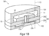
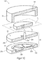
- the Figures 1A and 1B show a first embodiment of an expansion valve 100 according to the invention.
- the expansion valve 100 has at least one fluid inlet 101 and at least one fluid outlet 102.
- the expansion valve 100 also has a first valve element 10 with at least one first channel structure 11.
- the expansion valve 100 also has a second valve element 20.
- the second valve element 20, as shown here by way of example, can consist of two parts 20a, 20b. Further embodiments provide that the second valve element 20 is designed in one piece.
- the second valve element 20 has at least a second channel structure 22a, 22b and a third channel structure 23a, 23b.
- Channel structures in general, and the depicted channel structures 11, 22a, 22b, 23a, 23b in particular, are structures provided in the respective valve element 10, 20, e.g. in the form of recesses that provide a flow path for a fluid flowing through.
- the first valve element 10 and the second valve element 20 are movable relative to one another. As in particular in Figure 1B As can be seen, in a first position of the valve elements 10, 20 the first channel structure 11 and the second channel structure 22a, 22b are aligned with one another and form a first fluid flow path 110 with a first flow resistance between the fluid inlet 101 and the fluid outlet 102.
- the Figures 1C and 1D show a second position of the valve elements 10, 20.
- the first channel structure 11 and the third channel structure 23a, 23b are aligned with one another and form a second fluid flow path 111 with a second flow resistance between the Fluid inlet 101 and the fluid outlet 102.
- At least one section 22b of the second channel structure 22a, 22b also opens into the circumferential channel structure 55.
- the circumferential channel structure 55 connects the channel structures 22a, 22b, 23a, 23b formed in the second valve element 20 with one another and forms a common feed to the fluid outlet 102.
- the amount of the total flow resistance for the fluid flowing through can be composed of a) the flow resistance of the first channel structure 11 of the first valve element 10, b) the flow resistance of the respective channel structure 22a, 22b, 23a, 23b of the second valve element 20 and c) the flow resistance of the circumferential channel structure 55.
- the second valve element 20 can also, in addition to the second and third channel structures 22a, 22b; 23a, 23b, also further channel structures 24a, 24b; 25a, 25b. These are described in more detail below.
- the individual channel structures can have different, not necessarily constant, flow cross-sections along the channel length, i.e. a channel structure can have a variable flow cross section. According to conceivable embodiments of the invention, the flow cross-sections of the individual channel structures can either be constant or just variable.
- a variable flow cross section can be achieved, for example, in that the geometric cross section of the respective channel structure changes at least once over its channel length.
- a channel structure with a variable flow cross section can have a first location at a first point Flow cross-section and at a second point have a second flow cross-section different from the first flow cross-section.
- a channel structure can be designed in such a way that the flow cross section increases or decreases along the direction of fluid flow.
- the channel structure could have a first flow cross-section at the beginning and at the end and a second (smaller or larger) flow cross-section in between, e.g. in the form of a constriction and the like.
- the flow cross section of a channel structure can influence the flow rate of a fluid flowing through this channel structure. This means, for example, that with the same channel length, a smaller volume of a channel structure results in a smaller flow cross section of this channel structure, which opposes a greater flow resistance to the fluid flowing through, whereby the flow rate of the fluid can be throttled.
- channel structures are conceivable which have a round shape. These can be produced, for example, by means of drilling. However, it is also conceivable that the channel structures have a rectangular shape. These can be produced, for example, by means of milling. In principle, other geometric shapes of the channel structures are also conceivable, e.g. triangular, round, half-round, or polygonal. For example, a triangular-shaped channel structure can have a higher flow resistance than a square-shaped channel structure.
- different flow cross-sections oppose different flow resistances to the fluid and thus throttle the flow rate of the fluid to different degrees.
- channel structures with different flow cross-sections can also be referred to as different throttle stages for throttling the flow rate.
- the throttling also brings about a decrease in the pressure of the fluid flowing through, ie the pressure of the fluid at the fluid outlet 102 is lowered compared to the pressure of the fluid at the fluid inlet 101.
- the Expansion valve 100 relaxes the fluid. It can also, at least partially, evaporate.
- the individual channel structures can therefore be referred to as throttle stages, by means of which the expansion valve 100 according to the invention can throttle the flow rate or the mass flow of the fluid flowing through.
- the second channel structure 22a, 22b can have a first flow cross section
- the third channel structure 23a, 23b can have a second flow cross section that is different from the first flow cross section.
- the expansion valve 100 thus has at least two different throttle stages.
- the throttle stages can have throttle rates between almost 100% and almost 0%.
- the relative value of the throttling rates here relates to the throttling of the flow rate of the fluid between the fluid inlet 101 and the fluid outlet 102 based on a time period ⁇ t.
- a throttling rate of 100% means, for example, that the flow rate of the fluid from fluid inlet 101 to fluid outlet 102 is almost zero or equal to zero within this time period ⁇ t.
- the expansion valve 100 thus blocks the flow of the fluid.
- the expansion valve 100 can thus provide a “stop function” in which a flow of the fluid is stopped. Due to valve leaks which are known to the person skilled in the art and which often occur, the flow rate can only be almost at 0%, ie slightly above 0%. For example, a flow rate can be between 0% and 5% in the event of leaks that may occur.
- a throttling rate of almost 0% means that the flow of the fluid is almost not throttled, i.e. the flow rate of the fluid from fluid inlet 101 to fluid outlet 102 in the time period ⁇ t is almost 100%. Due to flow and friction losses within the channel structures through which the flow is flowing, the flow rate is usually only almost 100%, i.e. always slightly below 100%. For example, a flow rate can be between 95% and 100% here.
- the expansion valve 100 can thus provide an “open function” or also “free-flow function”, in which the fluid can flow through almost unhindered. In this case, there is therefore no significant throttling within the expansion valve 100.
- the expansion valve 100 has at least two throttle stages, i. the flow resistance of the first flow path in the first switching position differs from the flow resistance of the second flow path in the second switching position. At least one of the two flow resistances can be designed in such a way that the expansion valve 100 does not have any significant throttling in the respective switching position. That is to say, at least one of the two flow paths (first switching position or second switching position) forms an aforementioned "open function" or free-flow function ".
- Such an “open function” can be implemented, for example, in that the first and second channel structures 11; 22a, 22b or the first and third channel structures 11, which form the second fluid flow path; 23a, 23b as one through the first and second valve elements 10; 20 through opening, e.g. a bore of the same diameter, which opening has no significant restriction.
- the expansion valve 100 has a throttling rate of almost 0%, or can have a throttling rate between 0% and a maximum of 5%.
- a previously mentioned “stop function” can be implemented, for example, in that the first channel structure 11 in the first valve element 10 is not aligned with any of the channel structures 22a, 22b, 23a, 23b of the second valve element 20.
- This can be implemented, for example, in that the first valve element 10 is in a (not third switch position, which is e.g. between the first switch position ( Figure 1B ) and the second switch position ( Figure 1D ) can lie.
- the first channel structure 11 of the first valve element 10 thus no longer opens into a further channel structure in the second valve element 20 but directly on the surface 28 ( Figures 1A , 1D ) of the second valve element 20.
- the fluid is thus no longer conducted to the fluid outlet 102, ie the flow of the fluid is blocked or interrupted as a result.
- the first valve element 10 can be moved relative to the second valve element 20, for example by means of a stepping motor.
- One of the two valve elements 10, 20 is driven by means of the stepping motor and moved relative to the other of the two valve elements 10, 20.
- a transmission can be provided that reduces or translates the drive of the stepping motor accordingly.
- the stop function in the third switching position is between the first and the second switching position, this has particular advantages in terms of possible energy savings.
- an initial position of the valve element 10, 20 connected to the stepping motor is the third switching position.
- the stepper motor would not have to move the valve element 10, 20 all the way from the first switch position to the second switch position (or back), but in this case it is sufficient to move the valve element 10, 20 only from the third switch position to the first or to move the second switch position. Since the third switching position lies between the first and the second switching position, the stepper motor only has to cover half the distance.
- the first valve element 10 could be driven by the stepping motor.
- An alternative Embodiment in which the second valve element 20 can be driven will be described below with reference to FIG Figures 2A and 2 B described.
- the second valve element 20 is designed in two parts in this exemplary embodiment, ie the second valve element has a first part 20b and a second part 20a.
- the first part 20b of the second valve element 20 here has at least one section 22b, 23b of the second and third channel structures 22a, 22b; 23a, 23b. That is to say, these sections 22b, 23b of the channel structures are formed in the first part 20b of the second valve element 20.
- the channel structures 22a, 22b; 23a, 23b and in particular their sections 22b, 23b are also referred to as throttle channel structures.
- the section 22b of the second channel structure 22a, 22b can also be referred to as a first throttle channel section 22b
- the section 23b of the third channel structure 23a, 23b can also be referred to as a second throttle channel section 23b.
- the first part 20b of the second valve element 20 can also have at least one fluid outlet 102.
- the throttle channel structures or sections 22b, 23b of the second and third channel structures are each connected to the fluid outlet 102 within the first part 20b of the second valve element 20, for example by means of the circumferential channel structure 55.
- a seal is advantageously arranged between the first part 20b of the second valve element 20 and the second part 20a of the second valve element 20, which fluidly seals the second and third channel structures 22b, 23b formed in the first part 20b of the second valve element 20 from one another.
- This can in particular be a Teflon seal, since it is particularly temperature-resistant, pressure-resistant and age-resistant.
- Sealing of the two parts 20a, 20b of the valve element 20 can also be achieved, for example, in that the two parts 20a, 20b are glued, screwed or welded to one another, for example by means of friction or laser welding.
- valve elements 10, 20 can in principle have various geometric shapes, i.e. the valve elements 10, 20 can, for example, be in the form of a cylinder, a cube, a sphere, a hemisphere, a pyramid, a prism and the like.
- the channel structures 11, 22a, 22b, 23a, 23b formed in the respective valve elements 10, 20 can extend at least in sections in a radial direction and / or at least in sections in an axial direction. If the two valve elements 10, 20 are rotatable relative to one another, for example, along an axis of rotation, an axial direction and a radial direction can relate to this axis of rotation.
- first valve element 10 and the second valve element 20 are each cylindrical valve elements, the first channel structure 11 in the first valve element 10 extending at least in sections in the axial and / or radial direction and / or where the second and third channel structure 22a, 22b; 23a, 23b in the second valve element 20 extend at least in sections 22b, 23b in the radial and / or axial direction.
- first valve element 10 and the second valve element 20 are each circular cylinder-shaped valve elements and the first valve element 10 is aligned concentrically with the second valve element 20 in the axial direction.
- first valve element 10 and the second valve element 20 can each be shown here by way of example as cylindrical valve elements.
- a cylinder by definition, is characterized by the fact that a flat curve in a plane is shifted by a fixed distance along a straight line that is not contained in this plane. Two corresponding points of the curves and the shifted curve are connected by a segment. The entirety of these parallel lines forms the associated cylinder surface.
- the curve or the resulting lateral surface can have any shape.
- the first valve element 10 and the second Valve elements 20 are each designed in the shape of a circular cylinder, the first valve element 10 in the axial direction 33 ( Figure 1A ) can be aligned concentrically with the second valve element 20.
- the first channel structure 11 in the first valve element 10 extends at least in sections in the axial direction 33 ( Figure 1A ).
- the first channel structure 11 extends completely through the first valve element 10. In terms of manufacturing technology, this can be achieved, for example, in that a bore is made in the axial direction 33 through the first valve element 10.
- the first channel structure 11 could extend in the radial direction 34 in the first valve element 10. This is in Figure 1A indicated by way of example with the first channel structure 11 ′ shown in broken lines. In terms of manufacturing technology, this can be achieved, for example, by making a bore in the radial direction 34 through the first valve element 10 in the same. It would also be conceivable that the radially running first channel structure 11 'shown in dashed lines is milled, sawn, lasered or cut from the underside 12 of the first valve element 10 into the same by means of a separating process and / or is embossed, shaped and formed by means of forming processes / or is produced directly with primary forming processes such as injection molding.
- the first channel structure 11 extends both in sections in the radial direction 34 and in sections in the axial direction 33.
- the second and third channel structures 22a, 22b, 23a, 23b in the second valve element 20 extend at least in sections in the radial direction 34 ( Figure 1A ). More precisely, the throttle channel structures or sections 22b, 23b of the channel structures 22a, 22b, 23a, 23b arranged in the first part 20b of the second valve element 20 extend at least in sections in the radial direction 34. In terms of manufacturing, this can be achieved, for example, by the throttle channel structures or The sections 22b, 23b are milled, sawn, lasered or cut from above into the second valve element 20 by means of separating processes and / or embossed, molded and / or produced directly with primary forming processes such as injection molding. These are relatively simple process steps that facilitate production and thus can significantly reduce unit costs.
- the second channel structure 22a, 22b and / or the third channel structure 23a, 23b extends at least in sections in the axial direction 33 through the second valve element 20 or the first part 20b of the second valve element 20.
- the second channel structure 22a, 22b could have a flow cross-section that differs from the third channel structure 23a, 23b.
- the first valve element 10 has a surface 12 facing the second valve element 20 ( Figures 1A and 1C ).
- the first valve element 10 and the second valve element 20 can be moved relative to one another, specifically in the depicted plane E 1 that runs parallel to this surface 12.
- the two valve elements 10, 20 can, for example, be movable in translation with respect to one another in this plane E 1 and thus displaced with respect to one another.
- the first valve element 10 and the second valve element 20 can be rotated relative to one another in the illustrated exemplary embodiments, so that a movement from the first position of the valve elements 10, 20 ( Figure 1B ) to the second position of the valve elements 10, 20 ( Figure 1D ) can be executed by means of a rotation of the first valve element 10 relative to the second valve element 20.
- first valve element 10 can be rotated relative to the second valve element 20, for example by means of a stepping motor, or the second valve element 20 can be rotated relative to the first valve element 10.
- the expansion valve 100 can have a cover 30.
- the cover 30 has a recess 31.
- the cover 30 is immovably connected to the second valve element 20.
- the first valve element 10 is arranged within this cover 30 or within the recess 31 so as to be movable relative to the second valve element 20, and thus also relative to the cover 30.
- the first valve element 10 can therefore be arranged in the expansion valve 100 in a movable manner, in particular in a rotationally movable manner.
- the expansion valve 100 has an axis 41 which, for example, can be arranged non-rotatably on the second valve element 20 and / or on the cover 30.
- the first valve element 10 is movably, in particular rotatably, mounted on this axis 41 by means of a corresponding receptacle 42.
- the axis 41 is arranged centrally, ie in the center of the second valve element 20.
- the receptacle 42 of the first valve element 10 is also arranged centrally in the first valve element 10. That is, the first valve element 10 and the second valve element 20 are arranged concentrically about this axis 41. The first valve element 10 and the second valve element 20 are thus arranged concentrically with one another.
- the axis 41 is arranged off-center, ie not in the center of the second valve element 20.
- the first valve element 10 would then continue to be arranged concentrically to the axis 41.
- the first valve element 10 and the second valve element 20 would then, however, no longer be arranged concentrically but rather eccentrically to one another.
- Such an arrangement is for example in the Figures 9 and 10 which will be described in more detail later.
- the receptacle 42 in the first valve element 10 is eccentric, i. E. is not arranged in the center of the first valve element 10. Then the first valve element 10 would not be arranged concentrically but rather eccentrically with respect to the axis 41.
- an underside surface 27 of the cover 30 facing the second valve element 20 is coupled, for example glued, to a surface 28 of the second valve element 20.
- the cover 30 is arranged on the second valve element 20.
- the second valve element 20 can, so to speak, together with the cover 30 form a housing, in particular a fluid-tight housing.
- an inner wall 26 of the cover 30 to be coupled to a laterally circumferential outer wall 29a, 29b of the second valve element 20.
- the second valve element 20 would find space within the recess 31 of the cover 30.
- the second valve element 20, together with the cover 30, can form a housing, in particular a fluid-tight housing.
- An additional cover (not shown here) would then preferably be coupled to the underside surface 27 of the cover 30.
- the fluid inlet 101 can be arranged in the cover 30.
- a fluid inlet 101 ′ can be provided in the second valve element 20 and / or in the cover (not shown).
- this optional fluid inlet 101 ' is indicated with broken lines.
- the fluid inlet 101 can also be arranged laterally in the cover 30. However, there should be at least one fluid inlet that allows the Introduce fluid into the recess 31 of the cover 30 in order to direct the fluid to the channel structures of the two valve elements 10, 20.
- the first valve element 10 is arranged in front of the second valve element 20, based on the direction of flow of the fluid from the fluid inlet 101 to the fluid outlet 102.
- the fluid thus initially flows into the first valve element formed in the first valve element 10 Channel structure 11 and from there, depending on the switching position of the expansion valve 100, into at least one of the channel structures 22a, 22b, 23a, 23b arranged in the second valve element 20.
- the expansion valve 100 also has a cover 30, but with the difference that the cover 30 is immovably connected to the first valve element 10 and the second valve element 20 is arranged within the cover 30 so as to be movable relative to the first valve element 10.
- an axis 41 is non-rotatably arranged on the first valve element 10 and / or the housing 30.
- the second valve element 20 is also designed in two parts, the first part 20b and the second part 20a each being movably, in particular rotatably, mounted on this axis 41 by means of a corresponding receptacle 42.
- the axis 41 is arranged centrally, ie in the center of the first valve element 10.
- the receptacle 42 of the second valve element 20 is also arranged centrally in the second valve element 20. That is to say, the first valve element 10 and the second valve element 20 are arranged concentrically about this axis 41. The first valve element 10 and the second valve element 20 are thus arranged concentrically with one another.
- the axis 41 is arranged off-center, ie not in the center of the first valve element 10.
- the second valve element would then be 20 furthermore arranged concentrically to the axis 41.
- the first valve element 10 and the second valve element 20 would then, however, no longer be arranged concentrically but rather eccentrically to one another.
- the receptacle 42 in the second valve element 20 is off-center, i.e. is not arranged in the center of the second valve element 20. Then the second valve element 20 would not be arranged concentrically but eccentrically with respect to the axis 41.
- the second valve element 20 is arranged here in front of the first valve element 10, based on the direction of flow of the fluid from the fluid inlet 101 to the fluid outlet 102.
- the second valve element 20 is designed in two parts, a first part 20b of the second valve element 20 comprising the second and third channel structures 22a, 22b; 23a, 23b, and a second part 20a of the second valve element 20 has a closed cover of the second and third channel structures 22a, 22b; 23a, 23b forms.
- the channel structures 22a, 22b; 23a, 23b and in particular the radially extending sections 22b, 23b can also be referred to as throttle channel structures.
- the first channel structure 11 simultaneously forms the fluid outlet 102 of the expansion valve 100.
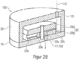
- Figure 2B shows a composite expansion valve 100 and the fluid flow path 112 resulting through the expansion valve 100.
- the fluid enters the expansion valve 100 through the fluid inlet 101, then flows through the channel structures 22a, 22b, 23a, 23b formed in the second valve element 20 and enters then out of the expansion valve 100 again through the fluid outlet 101, which is formed by the first channel structure 11 formed in the first valve element 10.
- the expansion valve 100 is in a first switching position. More precisely, the two valve elements 10, 20 are in a first position relative to one another, in this first position the first channel structure 11 and the second channel structure 22a, 22b are aligned with one another and a first fluid flow path 112 with a first flow resistance between the fluid inlet 101 and the fluid outlet 102 form.
- the second valve element 20 in contrast to that in FIG Figure 2B shown first switch position for example rotated by 180 °.
- first channel structure 11 and the third channel structure 23a, 23b would be aligned with one another and form a second fluid flow path with a second flow resistance different from the first flow resistance between the fluid inlet 101 and the fluid outlet 102.
- This individual circuit is distinguished, among other things, by the fact that in the first and second positions of the valve elements 10, 20 exactly one of the second and third channel structures 22a, 22b; 23a, 23b of the second valve element 20 is fluidically coupled to the fluid outlet 102 in order to form a single fluid flow path 111, 112 between the fluid inlet 101 and the fluid outlet 102.
- the second valve element 20 can also have further channel structures 24a, 24b, 25a, 25b in addition to the second and third channel structures 22a, 22b, 23a, 23b.
- the first valve element 10 has only one channel structure, namely the first channel structure 11.
- the two valve elements 10, 20 are moved relative to one another, for example by means of a stepper motor mentioned above, in such a way that the first channel structure 11 of the first valve element 10 only ever forms a single channel structure 22a, 22b, 23a, 23b, 24a, 24b, 25a, 25b of the second valve element 20 is aligned.
- the individual channel structures 22a, 22b, 23a, 23b, 24a, 24b, 25a, 25b of the second valve element 20 have different flow cross-sections.
- the throttling of the flow rate results on the one hand from the individual length and the individual flow cross-section of each individual channel structure 22a, 22b, 23a, 23b, 24a, 24b, 25a, 25b, which is not necessarily constant or geometrically variable over the channel length, and others by the length and the flow cross section of the common channel structure 55.
- Channel-specific fluid flow paths with individual throttling rates are thus formed.
- the individual channel structures can therefore be provided with a certain surface roughness. Tests have shown that when the surface roughness was set, differences in the throttling rate of up to 10% could be recognized in comparison to the fluidically smooth surface properties of the channel structures.
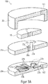
- FIG. 1A A series connection of the channel structures of the first embodiment ( Figures 1A to 1D ) is intended below with reference to the Figure 3A and 3B to be discribed.
- the series connection is characterized, among other things, in that the second channel structure 22a, 22b and the third channel structure 23a, 23b are connected to one another at least in sections 22b, 23b within the second valve element 20, i.e. at least the throttle channel structures 22b, 23b of the respective channel structures 22a, 22b ; 23a, 23b are connected to one another, wherein in the second position of the valve elements 10, 20 the second fluid flow path is composed of the second and the associated third channel structure 22b, 23b, and in particular of the respective throttle channel structures 22b, 23b, and the second fluid flow path has an overall flow resistance which is composed of the flow resistance of the second channel structure or throttle channel structure 22b and the flow resistance of the third channel structure or throttle channel structure 23b connected thereto.
- the second valve element 20 is again made in two parts.
- first part 20b several, here by way of example a total of five, different channel structures or throttle channel structures 22b, 23b, 24b, 25b, 26b are formed.
- the individual channel structures or throttle channel structures 22b, 23b, 24b, 25b, 26b are all fluidically connected to one another so that they form a long chain or a series connection of several channel structures or throttle channel structures.
- the expansion valve 100 has only one common fluid outlet 102, which is connected to the first or last channel structure or throttle channel structure 22b from the series connection.
- the fluid must travel paths of different lengths to the fluid outlet 102.
- the total flow resistance is composed of the individual flow resistances of the channel structures passed through.
- the individual channel structures, and in particular the throttle channel structures 22b, 23b, 24b, 25b, 26b can also have different flow cross-sections that are not necessarily constant or geometrically variable over the channel length.
- channel structures 22a, 23a, 24a, 25a, 26a which correspond to the channel structures or throttle channel structures 22b, 23b formed in the first part 20b of the second valve element 20 , 24b, 25b, 26b are aligned.
- the first valve element 10 is rotatable with respect to the second valve element 20 and has the first channel structure 11.
- the first channel structure 11 can now be optionally aligned in different switching stages to one of the channel structures 22a, 22b, 23a, 23b, 24a, 24b, 25a, 25b, 26a, 26b formed in the second valve element 20.
- a fluid flow path of different lengths is formed which the fluid flowing through must cover in order to reach the fluid outlet 102.
- FIG. 3B One of these several possible switch positions is exemplified in Figure 3B to see.
- the first valve element 10 is aligned with respect to the second valve element 20 such that the first channel structure 11 is aligned with the sixth channel structure 26a, 26b.
- the resulting fluid flow path is shown with the dashed arrow 121.
- the fluid thus enters the expansion valve 100 through the fluid inlet 101, then flows through the first channel structure 11, which is aligned with the sixth channel structure 26a, 26b, through all further channel structures or throttle channel structures 25b, 24b, 23b, and then afterwards Flow through the first channel structure or throttle channel structure 22b to open into the fluid outlet 102.
- This series connection is also characterized, inter alia, in that the second channel structure 22a, 22b and the third channel structure 23a, 23b are connected to one another at least in sections 22b, 23b within the second valve element 20, i.e. at least the throttle channel structures 22b, 23b are connected to one another, whereby In the second position of the valve elements 10, 20, the second fluid flow path is composed of the second and the third channel structure connected to it, and in particular the throttle channel structure 22b, 23b, and the second fluid flow path has an overall flow resistance that is derived from the flow resistance of the second channel structure, and in particular of the throttle channel structure 22b and the flow resistance of the third channel structure connected thereto, and in particular of the throttle channel structure 23b.
- the second valve element 20 is again made in two parts.
- first part 20b several, here by way of example a total of five, different channel structures 22a, 22b, 23a, 23b, 24a, 24b, 25a, 25b, 26a, 26b are formed.
- the individual channel structures 22a, 22b, 23a, 23b, 24a, 24b, 25a, 25b, 26a, 26b, or the sections 22b, 23b, 24b, 25b, 26b referred to as throttle channel structures are all fluidically connected to one another so that they form a long chain or form a series connection of several channel structures.
- each channel structure has a radial section 22b, 23b, 24b, 25b, 26b, also referred to as a throttle channel structure, and an axial section 22a, 23a, 24a, 25a, 26a.
- a throttle channel structure also referred to as a throttle channel structure
- an axial section 22a, 23a, 24a, 25a, 26a In the in Figure 4A In the sectional view shown, only the axial sections 22a and 26a of the second and sixth channel structure can be seen. The axial sections 23a, 24a, 25a of the other channel structures are covered in this sectional view and are therefore only indicated with broken lines.
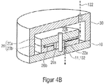
- the expansion valve 100 again has only one common fluid outlet 102, which at the same time also forms the first channel structure 11 of the first valve element 10.
- the second valve element 20 is rotatable relative to the first valve element 10 and can now optionally be rotated into different switching stages, with a different one of the channel structures 22a, 22b, 23a, 23b, 24a, 24b, 25a, 25b, 26a, 26b of the second in each switching stage Valve element 20 is aligned with the first channel structure 11 of the first valve element 10. More precisely, depending on the switching stage, an axial section 22a, 23a, 24a, 25a, 26a of the respective channel structure of the second valve element 20 is aligned with the first channel structure 11 of the first valve element 10.
- the fluid always enters the second valve element 20 through the radial section or throttle channel structure 22b of the second channel structure 22.
- the fluid must pass through the corresponding further channel structures 23a, 23b, 24a, 24b, 25a, 25b, 26a, 26b in addition to the second channel structure 22a, 22b.
- the fluid must therefore travel paths of different lengths to the fluid outlet 102.
- a fluid flow path of different lengths is thus formed which the fluid flowing through must cover in order to reach the fluid outlet 102.
- the total flow resistance is composed of the individual flow resistances of the channel structures passed through.
- the individual channel structures 22a, 22b, 23a, 23b, 24a, 24b, 25a, 25b, 26a, 26b can also have different flow cross-sections that are not necessarily constant or geometrically variable over the channel length.
- FIG. 4B One of these several possible switch positions is exemplified in Figure 4B to see.
- the second valve element 11 is arranged opposite the first valve element 10 in such a way that the second channel structure 22a, 22b is aligned with the first channel structure 11.
- the resulting fluid flow path is shown with the dashed arrow 122.
- the fluid flows through the radial section or the throttle duct structure 22b of the second duct structure into the second valve element 20 and flows through the axial section 22a of the second duct structure 20 to the first duct structure 11, which is also the fluid outlet 102.
- the second valve element 20 would be, for example, by 180 ° compared to that in FIG Figure 4B shown switch position rotated.
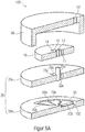
- expansion valve 100 according to the invention can also be used to connect the channel structures in parallel, as shown in FIGS Figures 5A to 6B is shown as an example.
- the parallel connection is characterized, among other things, by the fact that the first valve element 10 has at least one fourth channel structure 14, and in the first position of the valve elements 10, 20 the third channel structure 23a, 23b of the second valve element 20 and the fourth channel structure 14 of the first Valve elements 10 are aligned with one another and form a third fluid flow path with a third flow resistance between the fluid inlet 101 and the fluid outlet 102.
- the amount of the third flow resistance can differ from the amount of the first and / or second flow resistance. That is, the third fluid flow path can provide a third throttle stage.
- the first channel structure 11 of the first valve element 10 and the second channel structure 22a, 22b of the second valve element 20 are aligned with one another, and at the same time the second channel structure 14 of the first valve element 10 and the third channel structure 23a, 23b of the second valve element 20 aligned with one another.
- the first valve element 10 has at least one further channel structure 14.
- the first valve element 10 here even has three further channel structures, namely a seventh channel structure 14, an eighth channel structure 14 ′ and a ninth channel structure 14 ′′.
- the second valve element 20 corresponds essentially to that with reference to FIG Figures 1A to 1D described embodiment.
- the individual channel structures 11, 14, 14 ', 14 "of the first valve element 10 can be aligned with the channel structures, and in particular with the axial sections 22a, 23a, 24a, 25a, of the channel structures in the second valve element 20. This enables different switching positions , with a different number of the four channel structures 11, 14, 14 ', 14 "of the first valve element 10 being aligned with the four channel structures 22a, 23a, 24a, 25a of the second valve element 20, depending on the switching position.
- Figure 5B shows an example of a switching position in which all four channel structures 11, 14, 14 ', 14 "of the first valve element 10 are aligned with the four channel structures 22a, 23a, 24a, 25a of the second valve element 20.
- the resulting fluid flow is indicated by the arrow 123 is drawn.
- the fluid thus flows through all four channel structures 11, 14, 14 ', 14 "of the first valve element 10, as well as through all four channel structures 22a, 23a, 24a, 25a of the second valve element 20 aligned therewith.
- This is, so to speak, the largest switching stage , in which all channel structures are active at the same time. Accordingly, the flow rate of the fluid can be greatest in this switch position, since the fluid can flow through all channel structures simultaneously.
- the total flow resistance is again made up of the individual flow resistances of the respective channel structures passed through.
- the individual channel structures 22a, 22b, 23a, 23b, 24a, 24b, 25a, 25b, 26a, 26b also have different flow cross-sections that are not necessarily constant or geometrically variable over the channel length.
- a stop function could here, for example, by rotating the first valve element 10 by 180 ° compared to that in FIG Figure 5B switch position shown can be reached. None of the channel structures 11, 14, 14 ′, 14 ′′ of the first valve element 10 would be aligned with any of the channel structures 22a, 22b, 23a, 23b, 24a, 24b, 25a, 25b, 26a, 26b of the second valve element 20.
- the expansion valve 100 has precisely one fluid outlet 102 and the second and third channel structures 22a, 22b; 23a, 23b of the second valve element 20 can be fluidically coupled to this one fluid outlet 102. Even if not explicitly shown in the figures, it would also be possible for the expansion valves 100 according to the invention not to have exactly one, but at least one fluid outlet 102, i.e. the expansion valves 100 can also have a second, third, or any number of fluid outlets 102.
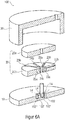
- the first valve element 10 has at least one further channel structure 14.
- the first valve element 10 here even has three further channel structures, namely a seventh channel structure 14, an eighth channel structure 14 ′ and a ninth channel structure 14 ′′.
- the second valve element 20 corresponds essentially to that with reference to FIG Figures 2A and 2 B described embodiment.
- the channel structures formed in the second valve element 20, namely a second channel structure 22a, 22b, a third channel structure 23a, 23b, a fourth channel structure 24a, 24b and a fifth channel structure 25a, 25b, have a radially extending section 22b, also referred to as a throttle channel structure , 23b, 24b, 25b, through which the fluid can flow into the second valve element 20, and an axial section 22a, 23a, 24a, 25a, which leads to at least one of the channel structures 11, 14, 14 'arranged in the first valve element 10 .14 "can be aligned.
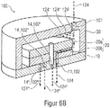
- Figure 6B shows the expansion valve 100 by way of example in FIG Figure 6A better visible switching position in which all four channel structures 22a, 23a, 24a, 25a of the second valve element 20 are aligned with the four channel structures 11, 14, 14 ', 14 ′′ of the first valve element 10.
- the resulting fluid flow is indicated by arrows 124 , 124 ', 124 ", 124'”.
- the fluid exits the expansion valve 100 through all activated fluid outlets 11, 14, 14 ', 14 ", which in turn is represented by the arrows 124', 124", 124 '"indicating the fluid flow is.
- the fluid first flows into the expansion valve 100 through the fluid inlet 101. It is then distributed over all four channel structures 22a, 22b, 23a, 23b, 24a, 24b, 25a, 25b in the second valve element 20, which is shown by the arrows 124, 124 ', 124 ", 124"'. That is, a first part 124 of the fluid flow enters the first channel structure 22a, 22b, a second part 124 'of the fluid flow enters the second channel structure 23a, 23b, a third part 124 "of the fluid flow enters the third channel structure 24a, 24b and a fourth portion 124 '"of the fluid flow enters the fourth channel structure 25a, 25b.
- the fluid thus flows through all four throttle channel structures or radial sections 22b, 23b, 24b, 25b of the four channel structures of the second valve element 20 into the second valve element 20.
- the fluid then flows into the axial sections 22a, 23a, 24a, 25a of the channel structures of the second valve element 20, which in the switching position shown are all aligned with a respective channel structure 11, 14, 14 ', 14 "of the first valve element 10.
- the fluid leaves the expansion valve 100 through the respective channel structures 11, 14, 14 ', 14 "of the first valve element 10, since these simultaneously form the multiple fluid outlets 102, 102', 102", 102 '"of the expansion valve.
- the total flow resistance is again made up of the individual flow resistances of the respective channel structures through which flow occurs.
- the individual channel structures 22a, 22b, 23a, 23b, 24a, 24b, 25a, 25b, 26a, 26b can also have different flow cross-sections that are not necessarily constant or geometrically variable over the channel length.
- a stop function could here, for example, by rotating the second valve element 20 by 180 ° compared to that in FIG Figure 6A switch position shown can be reached. None of the channel structures 22a, 22b, 23a, 23b, 24a, 24b, 25a, 25b, 26a, 26b of the second valve element 20 would be aligned with any of the channel structures 11, 14, 14 ', 14 "of the first valve element 10.
- the individual positions of the valve elements 10, 20 can be switched to one another in discrete steps.
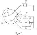
- the expansion valve 100 could in principle also have a combination of a parallel connection with a series connection. Such a case is exemplified in the form of a schematic block diagram in FIG Figure 7 shown.
- the fluid flow running through the expansion valve 100 first leads through a channel structure 22 with a first flow resistance 71 and then in a parallel connection of channel structures 23, 24, 25 with a second flow resistance 72, a third flow resistance 73 and a fourth flow resistance 74.
- the flow resistance 71, 72, 73, 74 can be the same size or different.
- the channel structure 22 is connected in series with the parallel connection of the channel structures 23, 24, 25.
- the total flow resistance is again made up of the individual flow resistances of the respective channel structures 22, 23, 24, 25 through which flow occurs.
- the expansion valve 100 can be made of different materials, i. the expansion valve 100 can, for example, comprise metal, plastic, glass or ceramic.
- the individual parts, i.e. the first valve element 10, the second valve element 20 and the cover 30 can be screwed, clamped, glued or welded together.
- the channel structures can be microchannel structures. These microchannel structures can flow cross-sections in Area of square millimeters or square micrometers.
- the microchannel structures can be introduced into the respective valve element 10, 20, for example, by means of precision milling, or they can be produced by means of injection molding or embossing. It is also conceivable that the microchannel structures are introduced into the respective valve element 10, 20 using etching processes, for example when the respective valve element 10, 20 contains silicon or other materials that are reactive to etchant.
- the expansion valve 100 can be arranged, for example, in a refrigeration circuit between two heat exchangers.
- Such heat exchangers can, for example, be so-called evaporators or condensers.
- the expansion valve can for example be arranged between such an evaporator and a condenser.
- the expansion valve 100 can also be arranged between at least two evaporators, which are followed by at least one condenser.
- a household refrigerator in particular a refrigerator and / or freezer, with an expansion valve 100 according to the invention is conceivable.
- This preferably means refrigerators and / or freezers with a cooling capacity of less than 1000 watts.
- these can be refrigerators, freezers, or fridge-freezers.
- the expansion valve 100 according to the invention can be used in any type of refrigeration machine, in particular in compression refrigeration machines.
- the expansion valve 100 can preferably be used in refrigerating machines with mass flows of less than 3 kg / h.
- the expansion valve 100 according to the invention can also have means for binding moisture.
- Zeolite for example, can be used as such a means for binding moisture.
- the zeolite is preferably used in the form of bulk material or as a sintered material.
- the means for binding moisture can, for example, be arranged upstream of the fluid inlet 101 in the direction of fluid flow.
- the means for binding moisture are preferably arranged between the fluid inlet 101 and the first or second valve element 10, 20.
- the means for binding moisture can for example be arranged in the recess 31 of the cover 30.
- the means for binding moisture can also be arranged in one or more of the channel structures 11, 14, 22, 23, 24, 25, 26 of the first and / or second valve element 10, 20, in particular when the means for binding Moisture in the form of loose bulk material.
- the means for binding moisture are advantageous in order to bind any moisture that may be present in the refrigerant and thus prevent unwanted ice formation elsewhere in the refrigeration circuit.
- the expansion valve 100 according to the invention can have at least one particle filter.
- the particle filter is advantageously arranged in the direction of flow after the means for binding moisture.
- the particle filter preferably filters particles which originate from the means for binding moisture, for example zeolite particles.
- the expansion valve 100 can, according to a further aspect of the invention, for example have a retaining element.
- a particulate filter just mentioned is one of several examples of such a retaining element. How such retaining elements for use on an expansion valve 100 according to the invention can look like, should be based on the following exemplary embodiments with reference to FIG Figures 11 to 21d are described in more detail.
- a retaining element can generally always be arranged along a fluid flow path flowing through the expansion valve 100 at any point in or on the expansion valve 100.
- Several retaining elements are also conceivable.
- Several retaining elements can be provided, with at least one retaining element being provided per throttle channel structure.
- a central retaining element can be provided with which at least two throttle duct structures are fluidically coupled.
- a retaining element which has at least two filter channel structures.
- the filter channel structures can for example be formed in the first valve element 10 his.
- the filter channel structures can be formed in the second valve element 20, or at least in a part 20a, 20b of the two-part second valve element 20.
- channel structures such as the filter channel structures, throttle channel structures and collecting channel structures described below
- the channel structures and in particular the filter channel structures 222 and / or the throttle channel structures 21b to 27b in the in Figure 2A depicted first part 20b of the two-part second valve element 20 are formed.
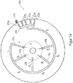
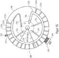
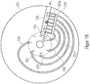
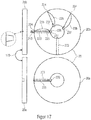
- the following Figures 11 and 13 to 17 thus show a top view of the in Figure 2A depicted first part 20b of the two-part second valve element 20.
- the filter channel structures 222 and / or the throttle channel structures 21b to 27b in the second part 20a of the second valve element 20 and / or in the first valve element 10 are trained.
- all of the channel structures described below can also be designed in the form of a throttle bore.
- a throttle bore can be designed, for example, as an axial bore extending through the first part 20b and / or the second part 20a of the second valve element 20 and / or through the first valve element 10.
- the axial direction 33 relates to the axis of rotation.
- FIG 11 shows Figure 11 a top view of the in Figure 2A
- the illustrated first part 20b of the two-part second valve element 20 The individual channel structures 22a, 22b; 23a, 23b; 24a, 24b; 25a, 25b, which are formed along the top of the first part 20b of the two-part second valve element 20 facing the viewer.
- the channel structures formed in the first part 20b of the second valve element 20 are used as a second channel structure 22a, 22b, a third channel structure 23a, 23b, and a fourth channel structure 24a, 24b and denotes a fifth channel structure 25a, 25b.
- the channel structures in this exemplary embodiment can each have an axially running section 22a, 23a, 24a, 25a and a radially running section 22b, 23b, 24b, 25b.
- the radial sections 22b, 23, 24b, 25b contribute the main part to the throttling of a fluid flowing through the channel structures.
- the radial sections are therefore also referred to as throttle channel structures 22b, 23b, 24b, 25b.
- the throttle channel structures 22b, 23b, 24b, 25b can have different flow resistances, for example due to different cross-sections.
- the second channel structure 22a, 22b can thus be a first throttle channel structure 22b with a specific cross section with any geometric shape, e.g. triangular, square, polygonal, trapezoidal, round, semicircular, etc., and the third channel structure 23a, 23b can have a second throttle channel structure 23b, which also has a certain cross-section with any shape.
- the cross section of the first throttle channel structure 22b can be the same as the cross section of the second throttle channel structure 23b.
- the respective cross-sections of the first throttle channel structure 22b and of the second throttle channel structure 23b can also differ from one another.
- the throttle channel structures 22b, 23b can have different flow resistances.
- the flow resistance can, for example, consist of a length of the flow-through throttle channel structure 22b, 23b, the cross-section of the flow-through throttle channel structure 22b, 23b that is not necessarily uniform along the channel length, a change in the flow-through cross-section or the channel course, a geometric cross-sectional shape, a roughness of the surface of the walls flow through throttle channel structure 22b, 23b, or result from a combination of these parameters.
- the different flow resistances throttle the flow of the fluid to different degrees.
- the throttling effect can be adjusted by varying the aforementioned parameters.
- expansion valve according to the invention, or in this exemplary embodiment the one in Figure 11 depicted second valve element 20, at least one retaining element 200 which is designed to retain a particle 210 located in the fluid flowing through the expansion valve 100.
- a first retaining element 200 is arranged in the region of the first throttle channel structure 22b.
- a second retaining element 200 ′ is arranged in the region of the fourth throttle channel structure 25b. According to the invention, however, one retaining element 200 is already sufficient.
- Each of the two retaining elements 200, 200 'shown here has at least two filter channel structures 222a, 222b; 225a, 225b, which are each fluidically coupled to at least one throttle channel structure 22b, 25b.
- the first retaining element 200 is connected to the first throttle channel structure 22b
- the second retaining element 200 ′ is connected to the fourth throttle channel structure 25b and is fluidically coupled.
- the filter channel structures 222a, 222b; 225a, 225b can, for example, be introduced into the second valve element 20 in the same way as the throttle channel structures 22b, 23b, 24b, 25b, for example by means of milling, laser cutting and the like.
- the filter channel structures 222a, 222b of the first retaining element 200 are fluidically coupled to the first throttle channel structure 22b. That is to say that a fluid exchange between the respective channel structures 222a, 222b; 22b is possible.
- the filter channel structures 225a, 225b of the second retaining element 200 ′ are fluidically coupled to the fourth throttle channel structure 25b. That is, a fluid exchange between the respective channel structures 225a, 225b; 25b is possible.
- the filter channel structures 222a, 222b; 225a, 225b are also led to the edge of the first part 20b of the second valve element 20 and provide a fluid inlet there. That is, fluid can there into the respective filter channel structures 222a, 222b; 225a, 225b flow in. The fluid that has flowed in then flows along the respective filter channel structure 222a, 222b; 225a, 225b into the respective throttle channel structure 22b, 25b which is fluidically coupled therewith.
- the filter channel structures 222a, 222b; 225a, 225b are designed to retain a particle 210.
- a particle 210 ′ clogs one of the two filter channel structures 225a, 225b of the second retaining element 200 ′ fluidically coupled to the fourth throttle channel structure 25b.
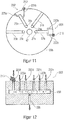
- FIG. 12 shows schematically a retaining element 200 with six filter channel structures 222a to 222f, all of which are fluidically coupled to the throttle channel structure 22b.
- the filter channel structures 222a to 222f are also arranged upstream of the throttle channel structure 22b in the direction of fluid flow.
- the filter channel structures 222a to 222f can therefore hold back a particle 210 before this particle 210 can penetrate into the respective throttle channel structure 22b and block it.
- the individual filter channel structures 222a to 222f can all have the same cross section or, as shown, different cross sections from one another.
- the cross section of the filter channel structures 222a to 222f is smaller than or equal to the cross section of the throttle channel structure 22b fluidically coupled therewith.
- the filter channel structures 222a to 222f can hold back a particle 210 that would be large enough to penetrate into the respective throttle channel structure 22b and block it.
- the cross section is at least the cross section of the fluid inlet surface into the respective channel structure 22b; 222a, 222b meant. That is, the cross section or the opening at the beginning of the channel structure 22b; 222a, 222b, through which the fluid into the respective channel structure 22b; 222a, 222b occurs.
- At least one filter channel structure 222a, 222b and at least one throttle channel structure 22b each have an angular cross section, and at least one side of the angular filter channel structure 222a, 222b can be smaller than or equal to a shortest side of the angular throttle channel structure 22b.
- the filter channel structure 222a, 222b could, for example, have a cross-section with dimensions of 40 ⁇ 40, around the top to be able to guarantee the retention or filter function described.
- the filter channel structure 222a, 222b could, however, also have a cross section with dimensions of 100 ⁇ 30 in order to be able to ensure the retention or filter function described above.
- at least one side of the angular filter channel structure 222a, 222b is therefore smaller than or the same size as a shortest side of the angular throttle channel structure 22b.
- At least one filter channel structure 222a, 222b and at least one throttle channel structure 22b could each have a round cross section, the cross section of the round filter channel structure 222a, 222b being smaller than the cross section of the round throttle channel structure 22b in order to achieve the above-described retention or retention structure. To be able to guarantee filter function.
- a collecting channel structure 230 can be arranged between the filter channel structures 222a to 222f and the throttle channel structure 22b fluidically coupled therewith.
- This collecting channel structure 230 can be fluidically coupled to the filter channel structures 222a to 222f and to at least one throttle channel structure 22b, so that a fluid flowing in through at least one filter channel structure 222a to 222f is collected in the collecting channel structure 230 and passed on into the at least one throttle channel structure 22b.
- the fluid thus flows into the filter channel structures 222a to 222f in the direction of the arrow shown. Since all filter channel structures 222a to 222f are fluidly coupled to the collecting channel structure 230, the fluid then flows further into this collecting channel structure 230 and is collected there. The fluid that has collected in the collecting duct structure 230 then also flows further in the direction of the arrow into the respective throttle duct structure 22b which is fluidically coupled to the collecting duct structure 230.
- the retaining element 200, 200 'shown can be arranged individually for each channel. That is, in each case one throttle channel structure 22b, 23b can be connected or fluidically coupled to one retaining element 200, 200 '.
- a central retaining element 200 is provided, which is connected or fluidically coupled to a plurality of throttle channel structures.
- at least two throttle channel structures 22b, 23b can be arranged directly on the collecting channel structure 230 and fluidically coupled to the collecting channel structure 230.
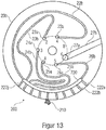
- a retaining element 200 is shown here, which has a plurality of filter channel structures 222a to 222j. Two or more, and preferably all, filter channel structures 222a to 222j are fluidically coupled to the collecting channel structure 230.
- the collecting channel structure 230 is in turn fluidically coupled to at least two, and preferably all, throttle channel structures 22b, 23b, 24b, 25b, 26b.
- the retaining element 200 is arranged upstream of the respective throttle channel structures 22b, 23b, 24b, 25b, 26b in the fluid flow direction in order to prevent a particle 210 from penetrating into the valve element 20 and clogging the throttle channel structures 22b, 23b, 24b, 25b, 26b.
- a throttle channel structure 27b can have a larger cross section than the other throttle channel structures 22b, 23b, 24b, 25b, 26b.
- the one throttle channel structure 27b with the largest cross section of all throttle channel structures 22b, 23b, 24b, 25b, 26b is not fluidically coupled to the collecting channel structure 230 here.
- the throttle channel structure 27b can also be implemented by a channel structure in the valve element 20a, for example by a bore that is implemented by continuing the bore 27a through the valve element 20a.
- this one throttle channel structure 27b with the largest cross section of all throttle channel structures 22b, 23b, 24b, 25b, 26b can provide an "open" function mentioned at the beginning.
- This one throttle channel structure 27b with the largest cross section of all throttle channel structures 22b, 23b, 24b, 25b, 26b here has almost no throttling, i.e. the fluid flowing through can flow through this one throttle channel structure 27 almost unhindered or unthrottled.
- a connecting channel structure segment V a may be disposed between at least one throttle channel structure 25b (V b) and the collecting channel structure 230 that connects said at least one throttle channel structure 25b (V b) and the collecting channel structure 230 with one another and fluidically coupled to each other.
- a central retaining element 200 is also provided, the central retaining element 200 having a plurality of filter channel structures 222a to 222e which open into a collecting channel structure 230.
- At least one second throttle channel structure 24b (IV b ) is also connected to the connecting channel structure segment V a and fluidically coupled, specifically by means of a further channel structure segment IV a .
- the connecting channel structure segment V a which connects the collecting channel structure 230 to the individual throttle channel structures 21b to 25b (I b to V b ) can, if necessary, cause a throttling of the fluid flowing through.
- the further channel structure segments I a to IV a can also cause a throttling of the fluid flowing through
- throttle channel structure with the largest cross section of all throttle channel structures I b to V b is not fluidically coupled to the collecting channel structure 230.
- throttle channel structure 26b with the largest cross section of all throttle channel structures 22b, 23b, 24b, 25b, 26b can be fluidically coupled not only to the collecting channel structure 230, but also to the collecting channel structure 230 at the same time form themselves, the filter channel structures 222a to 222u opening into this collecting channel structure 230.
- the collecting channel structure 230 is therefore directly connected and fluidically coupled to that throttle channel structure 26b with the largest cross section of all throttle channel structures 22b, 23b, 24b, 25b, 26b.
- the collecting channel structure 230 and the throttle channel structure 26b can here have the same cross section.
- At least two filter channel structures 222a, 222b and at least two throttle channel structures 22b, 23b are connected and fluidically coupled directly to the throttle channel structure 26b, which at the same time also forms the collecting channel structure 230.
- all filter channel structures 222a to 222u and all throttle channel structures 22b, 23b, 24b, 25b are connected and fluidically coupled directly to throttle channel structure 26b, which at the same time also forms collecting channel structure 230.
- a particle 210 clogs a filter channel structure 222r
- the fluid can flow through all the other non-clogged filter channel structures 222a to 222u into the throttle channel structure 26b or the collecting channel structure 230 and from there to the respective throttle channel structure 22b, 23b, 24b, 25b, 26b continue to flow.
- the collecting duct structure 230 was designed in the shape of an arc in the second valve element 20.
- the collecting channel structure 230 has, for example, in FIG Figure 15 is shown has a radius R S which is smaller than the radius R V of the second valve element 20.
- the filter channel structures 222a to 222u fluidly coupled to the collecting channel structure 230 can be arranged to run radially outward starting from the collecting channel structure 230, for example in FIG Figures 13 and 15th is shown.
- the filter channel structures 222a to 222u can also be arranged to run axially outward starting from the collecting channel structure 230, for example in the form of axial bores which open into the collecting channel structure 230.
- the filter channel structures 222a to 222u in the second valve element 20 can define an opening to the environment through which the fluid can flow into the respective filter channel structure 222a to 222u. From there, the fluid flows into the collecting channel structure 230 and from there then in turn into the respective throttle channel structures 22b, 23b, 24b, 25b, 26b.
- the throttle channel structures 22b, to 27b were all arranged in the fluid flow direction after the filter channel structures 222a to 222u, i.e. the fluid first flows into the filter channel structures 222a to 222u and then into the throttle channel structures 22b to 27b.
- Figure 16 shows a further embodiment, according to which that throttle channel structure 26b with the largest cross section of all throttle channel structures 22b, 23b, 24b, 25b, 26b is connected to the filter channel structures 222a to 222g and fluidically coupled, this one throttle channel structure 26b arranged in the fluid flow direction in front of the filter channel structures 222a to 222g is.
- the filter channel structures 222a to 222g can also be fluidically coupled to a channel structure in valve element 20a, for example a bore that is implemented by continuing the bore 26a through valve element 20a.
- the fluid first flows into the throttle channel structure 26b with the largest cross section, before the fluid then flows to the filter channel structures 222a to 222g and from there to the individual remaining throttle channel structures 21b, 22b, 23b, 24b, 25b.
- a particle 210 which has been washed away is thereby passed through the fluid outlet side, e.g. axially extending channel structure 26a to the fluid outlet 102 and thus conveyed out of the expansion valve 100.
- Figure 17 shows a further exemplary embodiment of an expansion valve 100 according to the invention.
- FIG first part 20b of the two-part second valve element 20 shown in the top right figure.
- a side view of the first part 20b of the two-part second valve element 20 can be seen.
- the second part 20a of the two-part second valve element 20 is shown schematically in plan view.
- a side view of the second part 20a of the two-part second valve element 20 can be seen in the illustration below on the left.
- the expansion valve 100 has a bypass channel structure 223.
- the bypass channel structure 223 can be formed, for example, in the second part 20a of the two-part second valve element 20, preferably on the side facing the first part 20b.
- the bypass channel structure 223 can, however, also be formed in the first valve element 10, for example.
- the bypass channel structure 223 forms a bypass in the fluid flow path for one or more throttle channel structures 21b, 22b, 23b. That is, the bypass channel structure 223 enables fluid to flow through the bypass if, for example, a throttle channel structure 21b, 22b, 23b is clogged by a particle 210 or the like.
- the bypass channel structure 223 can be fluidically coupled to at least one fluid inlet section 224 of at least one throttle channel structure 21b, so that when the bypass channel structure 223 is fluidically coupled to this at least one throttle channel structure 21b, a particle adhering to this fluid inlet section 224 210 can be removed through the bypass channel structure 223.
- the fluid inlet section 224 is that section of the throttle channel structure 21b through which the fluid flows into the throttle channel structure 21b.
- the fluid inlet section 224 of a throttle channel structure 21b, 22b, 23b is that section which is open to the environment and enables the fluid to enter the throttle channel structure 21b, 22b, 23b. It is, so to speak, the opening through which the fluid enters the respective throttle channel structure 21b, 22b, 23b.
- bypass channel structure 223 has a larger cross section than the throttle channel structures 21b, 22b, 23b.
- the particle 210 shown here has clogged the fluid inlet section 224 of the throttle channel structure 21b.
- the bypass channel structure 223 is arranged opposite the clogged throttle channel structure 21b in such a way that the bypass channel structure 223 is at least opposite the clogged fluid inlet section 224 of the throttle channel structure 21b.
- the bypass channel structure 223 thus forms a fluid flow path 225 from the fluid inlet section 224 of the clogged throttle channel structure 21b, along the bypass channel structure 223, to one end 226 of the bypass channel structure 223.
- This said end 226 of the bypass channel structure 223 can be, for example, an opening to the environment through which the entrained Particles 210 can be flushed out or removed.
- the end 226 of the bypass channel structure 223 can, however, also open into the fluid outlet 102 of the expansion valve 100 in order to convey the entrained particle 210 out of the expansion valve 100.
- the bypass channel structure 223 in the illustrated embodiment is fluidically coupled to a fluid outlet section 227 of the at least one throttle channel structure 21b.
- the fluid outlet section 227 of the respective throttle channel structure 21b, 22b, 23b can, for example, be the, for example axially extending, channel structure section 21a, 22a, 23a of the respective channel structure 21a, 21b; 22a, 22b; 23a, 23b. Since this fluid outlet section 227 is fluidically coupled to the fluid outlet 102 of the expansion valve 100, the bypass channel structure 223 can guide the fluid in this embodiment directly to the fluid outlet 102 of the expansion valve 100. An entrained particle 210 is thus washed out through the fluid outlet 102.
- the blocked throttle channel structure 21b mentioned here by way of example is therefore on the input side, i.e. at its fluid inlet section 224, and optionally also on the outlet side, i.e. at its fluid outlet section 227, can be fluidically coupled to the bypass channel structure 223.
- bypass channel structure 223 could come to overlap at least at the fluid inlet section 224 of a throttle channel structure 21b with this fluid inlet section 224.
- Bypass channel structure 223 also come to overlap at least at the fluid outlet section 227 of a throttle channel structure 21b with this same fluid outlet section 227.
- bypass channel structure 223 overlaps the throttle channel structure 21b over the entire length, this corresponds to a temporary increase in the effective cross section of the respective throttle channel structure 21b.
- the at least one throttle channel structure 21b can optionally have, at least in sections, a shape that widens towards the bypass channel structure 223.
- the figure at the top left in Figure 17 an enlarged illustration of the throttle channel structure 21b.
- the throttle channel structure 21b has a trapezoidal shape which widens towards the bypass channel structure 223.
- the two parts 20a, 20b of the two-part second valve element 20 are, as indicated by the arrow 170, placed one on top of the other.
- the bypass channel structure 223 and the throttle channel structure 21b are thus arranged opposite one another and the throttle channel structure 21b widens towards the bypass channel structure 223.
- the expansion valve 100 is a means 240 ( Figure 15 ) for releasing and / or removing a particle adhering to the retaining element 200, the means 240 for releasing and / or removing a particle having a mechanical stripping device 241 which can be brought into contact with the retaining element 200 and is movable relative to the retaining element 200 , and wherein the stripping device 241 is designed to mechanically remove a particle 210 adhering to the retaining element 200 when the retaining element 200 is moved relative to the stripping device 241.
- the means 240 for loosening and / or removing a particle here has a mechanical stripping device 241 which, in terms of its function, is roughly comparable to a broom.
- the stripping device 241 is here in contact with the circumference of the first part 20b of the two-part valve element 20 and is attached in a stationary manner. When the valve element 20 moves past the wiper device 241, then a valve element 20 becomes adhering particles 210 are stripped from the valve element 20 by means of the stripping device 241.
- the retaining element 200 has been described by way of example in the form of the filter channel structures 222. In principle, however, it is of course conceivable that the retaining element 200 has a perforated plate and / or sintered material and / or a fabric structure and / or a network structure and / or an open-pored sponge structure and / or loose bulk material and / or water-binding material.
- the retaining element 200 can bring about a fixed flow resistance for the fluid flow flowing through the retaining element 200. That is to say, the retaining element 200 itself can already provide a throttle function. In this case, the amount of this flow resistance can, for example, be at most as great as is necessary for a smallest throttle stage.
- the retaining element 200 can be designed to throttle the fluid flow flowing through the retaining element 200 by 10% or less, preferably by 20% or less, and more preferably by 30% or less. That is, the restraint element 200 offers a fixed restriction, for example 30% or less, based on the fluid flow before and after the restraint element 200.
- a retaining element 200 can also throttle the fluid flow to almost 100% in front of each throttle channel structure 21b, 22b, 23b, the respective throttle channel structure 21b, 22b, 23b not having to provide any further throttling.
- the retaining element 200 can have a means for reducing the flow velocity of a fluid flow flowing along one of the fluid flow paths, so that a settling area is formed in the respective fluid flow path, in which particles which have penetrated can settle.
- Such a means for reducing the flow velocity can have at least one baffle wall and / or an expansion space and / or a section with a cross-section that is larger than that of the throttle channel structure 21b, 22b, 23b.
- Figure 18 an example of a retaining element 200 which has such a means 250 for reducing the flow velocity.
- the means 250 for reducing the flow velocity has an expansion space 255 or a section with a cross section that is larger than that of the throttle channel structure 21b.
- the flow velocity at the end of the installation space extension 255 can have decreased in such a way that a settling area 252 for the particles 210 is formed there.
- baffle plates 251 can be arranged in the installation space extension 255.
- settling areas 253 can form, in which particles 210 can settle.
- the baffle plates 251 can, however, also be arranged in a throttle channel structure 21b to 27b or in a filter channel structure 222a to 222u, i.e. the combination of the installation space extension 255 with the baffle plates 251 is optional.
- the retaining element 200 in the illustrated embodiment also has a filter channel structure 222a, 222b described above.
- the retaining element 200 only has the means 250 for reducing the flow velocity, ie without a combination with an additional filter channel structure 222a, 222b.
- the filter channel structures 222a, 222b are arranged in the fluid flow direction between the means 250 for reducing the flow velocity and the respective throttle channel structure 21b.
- the direction of fluid flow resulting in this exemplary embodiment of a retaining element 200 is indicated by arrow 258.
- the fluid therefore initially flows into the installation space extension 250. If the previously mentioned baffle plates 251 are present, the fluid flows past these baffle plates 251, and settling areas 253 for particles 210 may form in the area of these baffle plates 251.
- the fluid then flows on into the filter channel structures 222a, 222b directly connected to it and fluidically coupled therewith.
- filters 222a, 222b By means of these filter channel structures 222a, 222b, particles 210 can likewise be removed in the manner described above be held back.
- the fluid then flows into the respective throttle channel structure 21b which is connected and fluidically coupled.
- a collecting channel structure 230 is arranged between the filter channel structures 222a, 222b and the throttle channel structure 21b.
- the means 250 for reducing the flow velocity is preferably fluidically coupled to at least one throttle channel structure 21b in order to keep particles 210 away from this throttle channel structure 21b.
- a settling region 252 can form in the means 250 for reducing the flow velocity. It would be conceivable here for the settling area 252 to be arranged in such a way that a particle adhering to the retaining element 200 when there is an existing fluid flow settles into the settling area 252 due to gravity when the fluid flow decreases. Such a case would be conceivable, for example, if the Figure 18 would be rotated by 180 ° and the fluid would flow against gravity, for example essentially from bottom to top.
- This function could therefore be implemented, for example, in that the restraint element 200 is flown against from below (i.e. against gravity), a particle 210 being able to stick to the underside of the restraint element 200 due to the force exerted by the flow.
- a retaining element 200 which, for example, only has the filter channel structures 222a, 222b, but not the means 250 for reducing the flow velocity.
- the present invention also provides options for removing particles 210 that have already entered the expansion valve 100, for example by flushing the expansion valve 100.
- flushing functions can be provided by means of the means described below.
- the two valve elements 10, 20 can be lifted from one another.
- at least one of the two valve elements 10, 20 can have a structure 261, 262 which causes the two valve elements 10, 20 to lift off from one another when the two valve elements 10, 20 move relative to one another, for example when they rotate and thereby forming a fluid flow path through which fluid can flow past the throttle channel structures 21b to the fluid outlet 102.
- first valve element 10 and the first part 20b of the two-part second valve element 20 including a throttle channel structure 21b formed in the first part 20b are shown.
- the first valve element 10 has an elevation 261.
- the second valve element 20 has a protruding portion 262.
- a gap 259 is thereby formed between the two valve elements 10, 20.
- This gap 259 provides a fluid flow path which, bypassing the throttle channel structures 21b, leads directly into the channel structure 11 of the first valve element 10 and thus directly to the fluid outlet 102.
- a particle 210 can thus be conducted directly to the fluid outlet 102 without this particle 210 having to first have passed through the throttle channel structures 21b.
- the throttle channel structures 21b, 22b, 23b, 24b, 25b, 26b and / or the filter channel structures 222a to 222u can be designed in such a way that their cross section can be temporarily enlarged.
- a particle 210 that has got caught in a channel structure can thereby be removed.
- a particle 210 clogs a throttle channel structure 21b, 22b, 23b, 24b, 25b, 26, for example, the first and second parts 20a, 20b of the two-part second valve element 20 can be lifted from one another, thus reducing the cross section of the respectively clogged throttle channel structure or to enlarge all throttle channel structures at least temporarily, as exemplified with reference to FIG Figure 19C should be explained.
- first part 20b and / or the second part 20a of the second two-part valve element 20 can be closed Figure 19A have similar structures 261, 262, which are not shown in greater detail here, which when the second two-part valve element 20 moves relative to the first valve element 10 and the housing 30 or when the two parts 20a, 20b move relative to one another, for example when rotating, that the two parts 20a, 20b stand out from one another.
- expansion valve 100 is shown, the structure of which is essentially that of FIG Figure 2A shown expansion valve 100 corresponds. That is, the expansion valve 100 has a first valve element 10 and a second valve element 20.
- the second valve element 20 is designed in two parts and has a first part 20b and a second part 20a.
- a housing 30 which has a fluid inlet 101 through which fluid can flow into the interior of the housing 30.
- the fluid inlet 101 is arranged on the top of the housing 30.
- an optional second fluid inlet 101 ′ is also shown here, which can be arranged in a side wall of the housing 30.
- a new sealing surface is created here at the fluid inlet 101, 101 '.
- first valve element 10 could close the aforementioned fluid inlets 101, 101 ', just analogous to that in the right illustration of FIG Figure 19C shown variant.
- the Figures 20A and 20B show a further possibility to flush particles 210 out of the expansion valve 100.
- one of the two valve elements 10, 20 has a channel structure 270 which, in the other of the two valve elements 10, 20, reverses the flow direction of the fluid flow flowing through this respective other valve element 10, 20.
- FIG. 20A So shows for example Figure 20A an embodiment in which initially only the right side, ie the right of the axis 41, is to be considered.
- a throttle channel structure 21b is formed in the second valve element 20.
- a first channel structure 269 is formed in the first valve element 10, through which the fluid can flow and flow into the throttle channel structure 21b. This results in the direction of flow of the fluid indicated by the arrows.
- the illustration to the left of the axis 41 shows a second position of the valve elements 10, 20.
- the second valve element 20 would be rotated by 180 ° relative to the first valve element 10.
- the throttle channel structure 21b is now arranged opposite another channel structure 270 formed in the first valve element 10. This is still the same throttle channel structure 21b, but in a different position, which is why this throttle channel structure is designated in this case with the reference symbol 21b '.
- the channel structure 270 formed in the first valve element 10 has the effect that the direction of fluid flow is reversed in the throttle channel structure 21b ', which is indicated by the arrows.
- a particle 210 that has possibly settled in the throttle channel structure 21b, 21b ′ can be flushed out in the opposite direction and through the expansion valve 100.
- Figure 20B shows a further embodiment for reversing the flow direction.
- a first position to the right of the axis 41
- the fluid flows through the first channel structure 269a into the throttle channel structure 21b and from there into the second channel structure 269b.
- the arrangement of the channel structures 269a, 269b relative to the throttle channel structure 21b results in the flow direction indicated by the arrows.
- the fluid flows here from the inside to the outside, ie away from the axis 41.
- a second switching position is then drawn in again to the left of the axis 41, the throttle channel structure also being denoted here with the reference symbol 21b '.
- the fluid flows through the first channel structure 270a into the throttle channel structure 21b 'and from there into the second channel structure 270b.
- the fluid flows here from the outside to the inside, i.e. towards the axis 41.
- a particle that has possibly settled in the throttle channel structure 21b, 21b ′ can be flushed out in the opposite direction and through the expansion valve 100.
- the expansion valve 100 according to the invention can be brought into several switching positions. This can be achieved, inter alia, in that the first valve element 10 is movable, in particular rotatable, relative to the second valve element 20.
- the expansion valve 100 can, for example, have a switching position in which the fluid flowing through is almost not throttled, i.e. the fluid flows through the expansion valve 100 almost unhindered.
- This switch position can therefore be referred to as the "open” function or as the free-flow switch position.
- the expansion valve 100 can also have a further switching position in which the flow of the fluid is almost completely throttled or blocked (i.e. with the exception of possible leakages). This switch position can therefore also be referred to as the "stop" position or blocking switch position.
- the throttle channel structures 21b, 22b, 23b, 24b, 25b, 26b form fluid flow paths with different throttle stages.
- the amount of the throttling effect can be determined here, for example, by the cross section of the respective throttle channel structure 21b, 22b, 23b, 24b, 25b, 26b. Since each throttle channel structure 21b, 22b, 23b, 24b, 25b, 26b thus enables the fluid to flow through, these switch positions are also referred to as flow switch positions.
- throttle channel structure 26b with the largest cross section of all throttle channel structures 21b, 22b, 23b, 24b, 25b, 26b can enable an almost unhindered flow or free flow, which is why this switch position can then accordingly also realize a free flow switch position.
- the expansion valve 100 can thus be brought into several positions, with that throttle channel structure 26b with the largest cross section of all throttle channel structures 21b, 22b, 23b, 24b, 25b, 26b forming the fluid flow path in a free-flow switching position, and in one Blocking switch position a fluid flow path is blocked.
- the individual switching positions can be achieved in that the first valve element 10 is movable, and in particular rotatable, relative to the second valve element 20.
- the expansion valve 100 by means of the relative movement between the first and the second valve element 10, 20 can be brought into a blocking switching position and into several flow switching positions, the expansion valve 100 providing a fluid flow path with a different flow resistance between the fluid inlet 101 and the fluid outlet 102 in each flow switching position, and wherein in the blocking switching position a fluid flow path between the fluid inlet 101 and the fluid outlet 102 is blocked.
- FIG. 21a to 21d each show a diagram for mapping a flow rate (y-axis) as a function of the switching position.
- the paths between the individual switch positions are represented by the number of steps (x-axis) that a stepper motor would have to move to in order to reach the respective switch positions.
- Figure 21a shows Figure 21a a diagram of an expansion valve 100 with linearly increasing flow or with linearly decreasing throttling.
- the origin of the diagram begins in the zero position of the expansion valve 100, in which there is no flow.
- the expansion valve 100 is here in a blocking switch position 380, which here serves as a reference or starting position.
- a first flow switch position 381 is reached after ten steps, for example.
- the expansion valve 100 has a first flow resistance or a first throttle stage.
- a second flow switching position 382 providing a second throttle stage is reached, this second throttle stage being lower than the first throttle stage.
- the expansion valve 100 thus has a lower flow resistance than in the first flow switch position 381.
- a third flow switching position 383 providing a third throttle stage is reached, this third throttle stage being less than the first and second throttle stages.
- the expansion valve 100 thus has a lower flow resistance than in the first and in the second switch position 381, 382.
- the individual flow switch positions 381 to 386 can be arranged in descending order with regard to their respective flow resistance, so that when the two valve elements 10, 20 move from one switch position 381 to the next switch position 382, the respective Reduced flow resistance.
- Figure 21b shows exactly the opposite, namely a diagram which depicts an expansion valve 100 with a linearly decreasing flow rate or with a linearly increasing flow resistance and thus a linearly increasing throttle rate.
- the individual flow switch positions 381 to 386 can be arranged in increasing order with respect to their respective flow resistance, so that when the two valve elements 10, 20 move from one switch position 381 to the next switch position 382, the respective Increased flow resistance.
- Figure 21c shows a diagram that represents an expansion valve 100 in which the individual switching stages 380 to 386 are arranged in any order.
- FIG 21d A diagram is shown which represents an expansion valve 100 in which the switching stages are arranged according to their frequency of use, the number 1 being the most frequent and the number 6 being the least frequent.
- the blocking switch position 380 (stop position) is provided between two stops of the expansion valve 100.
- the expansion valve 100 can be displaced rotating both to the left and to the right.
- the flow switch position 381 is used more frequently than the flow switch position 384. Starting from the blocking switch position 380, the flow switch position 381 can therefore be arranged closer to the blocking switch position 380 than the less frequently required flow switch position 384.
- the flow switch position 381 can be approached, for example, in ten steps, starting from the blocking switch position 380, while the flow switch position 384 can be approached with a total of twenty steps, starting from the blocking switch position 380.
- the flow switch position 381 is required more frequently than the flow switch position 384.
- the flow switch position 382 is also required frequently.
- the flow switch position 382 can, for example, be used less frequently than the flow switch position 381, but more frequently than the flow switch position 384.
- this flow switch position 382 can be approached with ten steps each, but in the other direction.
- the individual flow switch positions 381 to 386 are arranged here as a function of their frequency of use.
- the illustrated embodiment of the present invention can therefore be the individual flow switch positions 381 to 386, starting from the blocking switch position 380, arranged in a sequence with regard to their respective flow resistance, this sequence depending on how often the respective switch position 381 to 386 is required in operation.
- the individual switching positions are achieved by the relative movement of the two valve elements 10, 20 relative to one another.
- the relative movement of the two valve elements 10, 20 does not have to be carried out with a stepper motor.
- the diagrams described above in the Figures 21a to 21d were only described as an example based on the number of steps to be driven by a stepper motor. The diagrams primarily serve to show the individual switch positions, which of course can be independent of the presence of a stepper motor.
- the distance between two switching positions can simply be shortened accordingly.
- the distance to be covered during the relative movement of the two valve elements 10, 20 to reach a specific flow switch position 381 to 386 can be shorter for a flow switch position that is often required than for a flow switch position 381 that is less frequently required to 386.
- switch positions are those switch positions that are used in normal operation, e.g. several times a day.
- the expansion valve 100 has a blocking switch position 380 between two flow switch positions 381 to 386.
- a separate blocking switch position 380 can be provided between each flow switch position 381 to 386. This saves the need to turn the valve elements 10, 20 back to a central blocking switch position 380. This is an advantage in terms of energy saving, since a stepper motor, for example, has to take significantly fewer steps to get to a blocking switch position 380.
- the blocking switch position 380 (stop position), in particular in combination with the above-mentioned free flow switch position 386 ("open" function) results in further advantages for the expansion valve 100 according to the invention.
- a defrosting function can be provided with it.
- the expansion valve 100 can, for example, be designed to provide a defrosting function in that the expansion valve 100 is first in the blocking switch position 380, the pressurized fluid being heated. The expansion valve 100 can then be brought directly into the free-flow switch position 386, an evaporator fluidically coupled to the expansion valve 100 being flooded with the heated fluid.
- aspects of the present invention also provide a refrigerator and / or freezer with an expansion valve 100 as described above.
- such a refrigerator and / or freezer can have a compressor, an evaporator and a control device.
- the control device can be designed to determine at least one parameter including an air temperature and / or an evaporator temperature and / or a compressor run time and / or a compressor switching stage and / or an ambient temperature and / or a pressure.
- the control device can also be designed to activate a flushing function at which the expansion valve 100 is set such that the fluid flows through that throttle channel structure with the largest cross section of all throttle channel structures 26b. That is, the control device brings the expansion valve 100 into a free-flow switching position 386.
- the control device can also be designed to activate the flushing function at regular intervals, or a setpoint / actual value comparison of one or more of the aforementioned parameters (air temperature and / or an evaporator temperature and / or a compressor run time and / or a compressor switching stage and / or an ambient temperature and / or a pressure), the control device putting the refrigerator and / or freezer into a normal operating state if the result of the setpoint / actual value comparison is positive, and the control device if the result is negative
- the result of the setpoint / actual value comparison switches the refrigerator and / or freezer to an emergency function, in which the expansion valve 100 is brought into a flow switching position that has a throttle channel structure 21b, 22b, 23b, 24b, 25b with a smaller cross section.
- One object of the invention is a valve 100 that can throttle a fluid flow from almost 100% maximum flow to almost 0% flow in discrete steps.
- the primary application is seen as a micro-expansion valve 100 in refrigeration circuits in the lower refrigeration capacity range, since it solves the aforementioned problem of refrigerant metering at low mass flows.
- a possible drive for operation is in the Figures 9 and 10 shown.
- a stepper motor for example, can be used to rotate the turntable (first valve element 10 or second valve element 20).
- a rotatable disk (first valve element 10) is located on the valve seat 20.
- the distributor (first channel structure 11) in the turntable 10
- the flow through the valve 100 can be completely prevented or, on the other hand, one of the microfluidic channel structures 22b, 23b, 24b, 25b can be activated.
- each channel structure 22b, 23b, 24b, 25b represents a specific throttle stage.
- These channel structures 22b, 23b, 24b, 25b can therefore also be referred to as throttle channel structures .
- a structure in the valve seat 20 can also be designed so that no significant throttling takes place (passage).
- the valve seat 10 itself contains the main outlet 11, 102.
- the flow through the valve 100 can be completely prevented or one of the microfluidic channel structures 22b, 23b, 24b, 25b can be activated.
- a channel structure / rotary position can also be designed in such a way that there is no significant throttling (passage).
- the present invention can be viewed as a directional control valve with integrated, differently designed, rigid throttles.
- While adjustable flow control valves typically only change the effective cross section in a locally limited manner at one point (see needle valve), in the present case microfluidic channel structures are "switched", ie depending on the switching stage, different fluid paths may also flow through. If one compares the present one In the invention, for example, with a needle valve, the differences shown in Table 1 result. ⁇ b> Table 1: Comparison of the needle valve with the present invention. ⁇ /b> Needle valve Present invention Constant switching process N discrete switching steps Mechanical precision and positioning accuracy of the actuator determine the achievable flow accuracy. Only the precision of the microfluidic channel structures determines the achievable flow accuracy.
- Limited dynamic range It is not practical to map very small and large flows in a valve: Small flow requires precise mechanics because the smallest valve gap, but this precise mechanics is too slow for larger flows.
- the implementation forms A and B can be understood as a combination of a (macroscopic) directional control valve based on a turntable and (microscopic) microfluidic channels for throttling.
- the channel structures are individually interconnected according to a).
- FIG. 9 An embodiment of the above-mentioned embodiment A ( Figures 1A to 1D ) is in Figure 9 shown.
- This embodiment of an expansion valve 100 according to the invention has a single-stage gear reduction with a first gear 91 and a second gear 92 meshing therewith.
- the second gear 92 is shown in more detail in the enlarged illustration at the top right. It is mechanically and preferably non-rotatably connected to the first valve element 10.
- the figure at the bottom right shows an enlarged illustration of the second valve element 20, which consists of a first part 20b and a second part 20a.
- the channel structures, and in particular the throttle channel structures 22b, 23b, 24b, can be contained in the upper plate part 20a as shown
- the channel structures, and in particular the throttle channel structures 22b, 23b, 24b, can, however, also be formed in the lower plate part 20b or optionally also in both plate parts 20a, 20b.
- the formation of the channel structures or throttle channel structures 22b, 23b, 24b in the upper plate part 20a can have advantages in terms of manufacturing technology.
- the throttle channels 22b, 23b, 24b lead to a collecting channel 55 (with no or hardly any throttling), which in turn leads to the outlet 102.
- the inlets are controlled via a recess 11 in the turntable (first valve element) 10.
- FIG. 10 An embodiment of the above-mentioned embodiment B ( Figures 2A and 2 B ) is in Figure 10 shown.
- This embodiment of an expansion valve 100 according to the invention also has a single-stage gear reduction with a first gear 91 and a second gear 92 meshing therewith.
- the second gear 92 is shown in greater detail in the enlargement (figure on the right).
- the second gear 92 forms the second part 20a of the two-part second valve element 20.
- the channel structures, and in particular the throttle channel structures 22b, 23b, 24b can be formed in the upper part 20a of the two-part second valve element 20, as shown.
- the channel structures, and in particular the throttle channel structures 22b, 23b, 24b, but also in the lower part 20b of the two-part second valve element 20, or optionally also in both parts 20a, 20b of the two-part second valve element 20, can be formed.
- Channel structures are preferably provided in the upper or lower part 20a, 20b of the two-part second valve element 20.
- a seal 93 e.g. a Teflon flat gasket.
- the channel structures 22a, 22b; 23a, 23b; 24a, 24b; 25a, 25b can be clogged by particles 210 that are larger than the channel cross-section.
- a blockage reduces or completely prevents the flow through the expansion valve 100 and thus changes the entire operating behavior.
- a filter structure or a retaining element 200 typically consists of a multiplicity of pores which are smaller than the particles 210 to be filtered out. Particles 210 which are larger than the pores of the filter 200 can therefore neither penetrate into the filter structure 200 nor penetrate it. This effect is known as the sieve effect. Due to the large number of parallel pores, one or more clogged pores do not or only slightly reduce the flow through the filter 200. The pores do not necessarily have to be of the same size.
- the filter structure or the retaining element 200 can be designed in such a way that it does not cause any significant throttling of the fluid flow (e.g. refrigerant).
- the filter structure or the retaining element 200 can, however, also be designed in such a way that, in addition to the subsequent throttle channel structures 21b to 27b, it generates part of the total throttling, i.e. the restraint element 200 generates, for example, a fixed 20% of the maximum throttling and the subsequent throttle channel structures 21b to 27b still implement the remaining 0% -80%, depending on the switching position.
- the filter structure or the retaining element 200 can simultaneously also serve as a moisture collector (e.g. together with zeolite) in order to remove residual moisture from the refrigeration system.
- a moisture collector e.g. together with zeolite
- Filter systems 200 can e.g. through perforated plates, sintered materials, fabric, nets, open-pored sponges, etc. but also through channel structures, and in particular through the filter channel structures described above.
- a filter effect can be generated by a filter structure consisting of parallel filter channel structures (input channels) 222a to 222u, which have the same or smaller dimensions than Subsequent channel structure (throttle channel structure) 21b to 27b and again bundled onto the relevant channel, the input channels not necessarily all having to be the same in cross section and length, as was already done with reference to FIG Figures 11 to 16 has been described. If, for example, the channel structure has a 50x40 cross-section, then both 40x40 could function as a filter, but also 100x30, ie it is not advisable to speak of a smaller "cross-section" for the input channels.
- the channel structures 11, 22a, 22b, 102 also need not necessarily be uniform, e.g. constant diameter. Asymmetrical or other geometries are also possible, e.g. conical or alternating inside diameters, which applies to all of the channel structures 11, 22a, 22b, 102 described above.
- an inlet channel (filter channel structure) 222a to 222u If an inlet channel (filter channel structure) 222a to 222u is blocked by a particle 210, the fluid can still flow in through the other inlet channels 222a to 222u.
- the number and size of the inlet channels 222a to 222u can additionally be selected such that inlet channels 222a to 222u which are clogged up to a certain extent do not or only slightly reduce the flow.
- the filter structure 200 shown with parallel input channels 222a to 222g can be connected individually upstream of each relevant channel, and in particular each throttle channel structure 22b, 23b, 24b, 25b.
- any “open” position that may be present ie a position in which there is no or almost no throttling by the channel structures, can be independent of this.
- Such an "open” position is, for example, provided by the in Figure 13 illustrated switching stage 6 with a larger cross-section.
- FIG Figure 14 Another arrangement with a central filter structure (retaining element) 200 is shown in FIG Figure 14 shown.
- the advantage of this arrangement is that, on the one hand, only one filter structure or a retaining element 200 is required and, on the other hand, the duct length can be saved because duct structure segments I a to V a and I b to V b can be used multiple times for the various switching stages: Level / Position 1: smallest flow / largest restriction Level / position 2: highest flow rate / lowest throttling Step 1: Canal segments Va + IVa + IIIa + IIa + Ia + Ib Level 2: Canal segments Va + IVa + IIIa + IIa + IIb Level 3: Canal segments Va + IVa + IIIa + IIIb Level 4: Canal segments Va + IVa + IVb Level 5: Channel segments Va + Vb
- the filter structure or the retaining element 200 can be attached to a wider “collecting channel structure” without a throttle function 26b or 230, as in FIG Figure 15 shown, is connected, which at the same time can realize the already mentioned "open” position, here switching stage 6.
- a filter / channel structure 222a to 222u can only hold back a limited amount of particles 210 without the flow through the expansion valve 100 being significantly reduced. From a certain loading with particles 210, e.g. the complete filter 200 clogs and the particles 210 have to be removed, e.g. passed through the expansion valve 100.
- the filter structure or the retaining element 200 is designed in such a way that the channel structure 26b required for the “open” position leads past the retaining element 200, as in FIG Figure 16 shown, then, after switching to the “open” position 6, the fluid (for example refrigerant) flows past the retaining element 200. Particles 210 can thus be carried along, passed through the expansion valve 100, and thus the retaining element 200 flushed free again, since the "open function" 26b provides much larger channel cross-sections than the throttle channel structures 21b to 25b for throttling.
- the particles 210 are probably still on the "inlet side” and can possibly get stuck again, but the filter / channel comes free and if reversed again they would perhaps / probably no longer get stuck in the same place and possibly through the "open" position can be flushed out.
- Figure 21d shows stop positions and an exemplary arrangement around the stop position according to the frequency of use: 1 most frequently, 6 the least.
- expansion valve 100 Another aspect of the expansion valve 100 according to the invention is that the passage or getting rid of particles 210 through the expansion valve 100, past the channel structures 21b, by deliberately lifting the entire disc (e.g. first valve element 10) from the valve seat (e.g. second valve element 20) takes place at one or more rotational positions, as in the Figures 19A and 19B sketched as an example. At the same time, the open position can also be realized in this way.
- the entire disc e.g. first valve element 10
- the valve seat e.g. second valve element 20
Landscapes
- Engineering & Computer Science (AREA)
- General Engineering & Computer Science (AREA)
- Mechanical Engineering (AREA)
- Physics & Mathematics (AREA)
- Thermal Sciences (AREA)
- Multiple-Way Valves (AREA)
- Lift Valve (AREA)
Claims (15)
- Soupape de détente (100) pour réduire une pression d'un fluide circulant à travers la soupape de détente (100) le long d'un trajet de circulation de fluide (110, 111, 112, 121, 122, 123), la soupape de détente (100) présentant:au moins une entrée de fluide (101) et au moins une sortie de fluide (102),un premier élément de soupape (10) avec au moins une première structure de canal (11),un deuxième élément de soupape (20) avec au moins une deuxième structure de canal (22a, 22b) et une troisième structure de canal (23a, 23b),dans laquelle le premier élément de soupape (10) et le deuxième élément de soupape (20) sont déplaçables l'un par rapport à l'autre,dans laquelle, dans une première position des éléments de soupape (10, 20), la première structure de canal (11) et la deuxième structure de canal (22a, 22b) sont orientées l'une par rapport à l'autre et constituent un premier trajet de circulation de fluide avec une première résistance à la circulation entre l'entrée de fluide (101) et la sortie de fluide (102),dans laquelle, dans une deuxième position des éléments de soupape (10, 20), la première structure de canal (11) et la troisième structure de canal (23a, 23b) sont orientées l'une par rapport à l'autre et constituent un deuxième trajet de circulation de fluide avec une deuxième résistance à la circulation différente de la première résistance à la circulation entre l'entrée de fluide (101) et la sortie de fluide (102), etdans laquelle la deuxième structure de canal (22a, 22b) présente une première section transversale de circulation variable ou constante, et dans laquelle la troisième structure de canal (23a, 23b) présente une deuxième section transversale de circulation variable ou constante différente de la première section transversale de circulation, où les différentes sections transversales de circulation opposent au fluide des résistances à la circulation différentes et étranglent la circulation du fluide selon un degré différent.
- Soupape de détente selon la revendication 1,
dans laquelle la quantité d'étranglement de la circulation du fluide est déterminée par la résistance à la circulation des structures de canal individuelles. - Soupape de détente (100) selon l'une des revendications précédentes,
dans laquelle la première structure de canal (11) dans le premier élément de soupape (10) s'étend au moins par segments dans la direction axiale (33), et/ou
dans laquelle la deuxième et la troisième structure de canal (22a, 22b; 23a, 23b) dans le deuxième élément de soupape (20) s'étendent au moins par segments (22b, 23b) dans la direction radiale (34) et/ou dans la direction axiale (33), et
dans laquelle les segments radiaux (22b, 23b) contribuent pour la part principale à l'étranglement du fluide circulant à travers les structures de canal. - Soupape de détente (100) selon l'une des revendications précédentes,
dans laquelle le premier élément de soupape (10) présente une surface (12) faisant face au deuxième élément de soupape (20) et le deuxième élément de soupape (20) est déplaçable par rapport au premier élément de soupape (10) dans un plan (E1) parallèle à cette surface (12). - Soupape de détente (100) selon l'une des revendications précédentes,
dans laquelle le deuxième élément de soupape (20) est réalisé en deux parties (20a, 20b), dans laquelle une première partie (20b) du deuxième élément de soupape présente au moins un segment (22b, 23b) des deuxième et troisième structures de canal (22a, 22b; 23a, 23b) ainsi que la sortie de fluide (102), où ces segments (22b, 23b) des deuxième et troisième structures de canal (22a, 22b; 23a, 23b) sont connectés, chacun, dans la première partie (20b) du deuxième élément de soupape à la sortie de fluide (102), et/ou
dans laquelle le premier élément de soupape (10) est disposé de manière rotative sur le deuxième élément de soupape (20), et dans laquelle l'une respective des deuxième et troisième structures de canal (22a, 22b, 23a, 23b) est dégagée au moyen d'un positionnement en rotation de la première structure de canal (11) en orientant la première structure de canal (11) dans différentes positions des éléments de soupape (10, 20) de manière sélective vers l'une des deuxième et troisième structures de canal (22a, 22b, 23a, 23b) réalisées dans le deuxième élément de soupape (20), et/ou
dans laquelle la deuxième et la troisième structure de canal (22a, 22b, 23a, 23b) débouchent, chacune, dans une structure de canal périphérique (55) qui relie les deuxième et troisième structures de canal (22a, 22b, 23a, 23b) l'une à l'autre et constitue une alimentation commune vers la sortie de fluide (102). - Soupape de détente selon la revendication 5,
dans laquelle au moins un segment (22a, 23a) des deuxième et troisième structures de canal (22a, 22b; 23a, 23b) est disposé dans la deuxième partie (20a) du deuxième élément de soupape en deux parties (20), et dans laquelle la première partie (20b) du deuxième élément de soupape (20) en deux parties présente la sortie de fluide (102) et au moins un autre segment (22b, 23b) des deuxième et troisième structures de canal (22a, 22b, 23a, 23b) est réalisé dans la première partie (20b) du deuxième élément de soupape en deux parties (20) et connecté respectivement, au moyen de la structure de canal périphérique (55), à la sortie de fluide (102), ou
dans laquelle la première partie (20b) du deuxième élément de soupape en deux parties (20) présente la sortie de fluide (102), et les deuxième et troisième structures de canal (22a, 22b, 23a, 23b) sont réalisées dans la deuxième partie (20a) du deuxième élément de soupape en deux parties (20) et connectées respectivement, au moyen de la structure de canal périphérique (55), à la sortie de fluide (102). - Soupape de détente (100) selon l'une des revendications 1 à 4,
dans laquelle la soupape de détente (100) présente un couvercle (30), dans laquelle le couvercle (30) est connecté de manière immobile au premier élément de soupape (10) et le deuxième élément de soupape (20) est disposé à l'intérieur du couvercle (30) de manière déplaçable par rapport au premier élément de soupape (10), et
dans laquelle la première structure de canal (11) constitue la sortie de fluide (102) de la soupape de détente (100), et dans laquelle l'une respective des deuxième et troisième structures de canal (22a, 22b, 23a, 23b) est dégagée au moyen d'un positionnement en rotation du deuxième élément de soupape (20) sur le premier élément de soupape (10) en orientant, dans la première et la deuxième position des éléments de soupape (10, 20), l'une respective des deuxième et troisième structures de canal (22a, 22b, 23a, 23b) du deuxième élément de soupape (20) de manière sélective vers la première structure de canal (11) du premier élément de soupape (10). - Soupape de détente (100) selon l'une des revendications précédentes,
dans laquelle, dans la première et la deuxième position des éléments de soupape (10, 20), chaque fois exactement une seule des deuxième et troisième structures de canal (22a, 22b; 23a, 23b) du deuxième élément de soupape (20) est orientée par rapport à la première structure de canal du premier élément de soupape (10, 20) pour former un seul trajet de circulation de fluide entre l'entrée de fluide (101) et la sortie de fluide (102). - Soupape de détente (100) selon l'une des revendications 1 à 7,
dans laquelle la deuxième structure de canal (22a, 22b) et la troisième structure de canal (23a, 23b) sont connectées l'une à l'autre au moins par segments (22b, 23b) dans le deuxième élément de soupape (20), dans laquelle, dans la deuxième position des éléments de soupape (10, 20), le deuxième trajet de circulation de fluide se compose de la deuxième et de la troisième structure de canal connectée à cette dernière (22b, 23b), et le deuxième trajet de circulation de fluide présente une résistance à la circulation globale qui se compose de la résistance à la circulation de la deuxième structure de canal (22b) et de la résistance à la circulation de la troisième structure de canal (23b) connectée à cette dernière, ou
dans laquelle le premier élément de soupape (10) présente au moins une quatrième structure de canal (14), et dans laquelle, dans la première position des éléments de soupape (10, 20), en outre la troisième structure de canal (23a, 23b) et la quatrième structure de canal (14) sont orientées l'une vers l'autre et constituent un troisième trajet de circulation de fluide avec une troisième résistance à la circulation entre l'entrée de fluide (101) et la sortie de fluide (102). - Soupape de détente (100) selon l'une des revendications précédentes,
dans laquelle la soupape de détente (100) présente un élément de retenue (200) destiné à retenir une particule (210) se trouvant dans le fluide, et
dans laquelle l'élément de retenue (200) présente au moins deux structures de canal à filtre (222a, 222b) qui sont couplées, chacune, en fluide à au moins une structure de canal d'étranglement (22b), et
dans laquelle la section transversale des structures de canal à filtre (222a, 222b) est inférieure ou égale à la section transversale de la structure de canal d'étranglement (22b) couplée en fluide respectivement à ces dernières, et/ou
dans laquelle au moins une structure de canal à filtre (222a, 222b) et au moins une structure de canal d'étranglement (22b, 23b) présentent, chacune, une section transversale angulaire et au moins un côté de la structure de canal à filtre angulaire (222a, 222b) est inférieure ou égale à un côté le plus court de la structure de canal d'étranglement angulaire (22b, 23b), et/ou
dans laquelle au moins une structure de canal à filtre (222a, 222b) et au moins une structure de canal d'étranglement (22b, 23b) présentent, chacune, une section transversale ronde, où la section transversale de la structure de canal à filtre ronde (222a, 222b) est inférieure à la section transversale de la structure de canal d'étranglement ronde. - Soupape de détente (100) selon la revendication 10,
dans laquelle est disposée, entre les structures de canal à filtre (222a, 222b) et les structures de canal d'étranglement (22b, 23b), une structure de canal de collecte (230) qui est respectivement couplée en fluide aux structures de canal à filtre (222a, 222b) et à au moins une structure de canal d'étranglement (22b), de sorte qu'un fluide entrant à travers au moins une structure de canal à filtre (222a, 222b) soit collecté dans la structure de canal de collecte (230) et soit transmis vers cette au moins une structure de canal d'étranglement (22b). - Soupape de détente (100) selon la revendication 11,
dans laquelle la structure de canal d'étranglement (26) à la section transversale la plus grande de toutes les structures de canal d'étranglement (21b, 22b, 23b, 24b, 25b, 26b) est connectée et couplée en fluide aux structures de canal à filtre (222a à 222g), dans laquelle cette une structure de canal d'étranglement (26b) est disposée devant les structures de canal à filtre (222a à 222g) dans la direction de circulation de fluide, et/ou
dans laquelle la soupape de détente (100) peut être amenée dans plusieurs positions, dans laquelle, dans une position de commutation de circulation libre (386), la structure de canal d'étranglement (26b, 27b) à la section transversale la plus grande de toutes les structures de canal d'étranglement (22b, 23b, 24b, 25b, 26b, 27b) constitue le trajet de circulation de fluide à travers la soupape de détente (100) et, dans une position de commutation de blocage (380), bloque un trajet de circulation de fluide. - Soupape de détente (100) selon la revendication 12,
dans laquelle la soupape de détente (100) est conçue pour mettre à disposition une fonction de dégivrage en ce que la soupape de détente (100) se trouve tout d'abord dans la position de commutation de blocage (380), où le fluide sous pression est chauffé, et que la soupape de détente (100) est ensuite amenée dans la position de commutation de circulation libre (386), où un évaporateur couplé en fluide à la soupape de détente (100) est inondé par le fluide chauffé. - Soupape de détente (100) selon l'une des revendications précédentes,
dans laquelle la soupape de détente (100) peut être amenée, au moyen du mouvement relatif entre le premier et le deuxième élément de soupape (10, 20), dans une position de commutation de blocage (380) et dans plusieurs positions de commutation de circulation (381 à 386), dans laquelle la soupape de détente (100) met à disposition, dans chaque position de commutation de circulation (381 à 386), un trajet de circulation de fluide respectivement avec une résistance à la circulation différente entre l'entrée de fluide (101) et la sortie de fluide (102), et dans laquelle, dans la position de commutation de blocage (380), un trajet de circulation de fluide entre l'entrée de fluide (101) et la sortie de fluide (102) est bloqué, et
dans laquelle les positions de commutation de circulation individuelles (381 à 386), en partant de la position de commutation de blocage (380), sont disposées dans un ordre croissant ou décroissant par rapport à leur résistance à la circulation respective, de sorte que, lors d'un mouvement relatif des deux éléments de soupape (10, 20) d'une position de commutation (381) à la position de commutation suivante respective (382), la résistance à la circulation respective augmente ou diminue, et/ou
dans laquelle les positions de commutation de circulation individuelles (381 à 386), en partant de la position de commutation de blocage (380), sont disposées dans un ordre en ce qui concerne leur résistance à la circulation respective, où cet ordre est fonction de la fréquence selon laquelle la position de commutation respective (380 à 386) est requise en fonctionnement. - Réfrigérateur et/ou congélateur avec une soupape de détente (100) selon l'une des revendications précédentes.
Applications Claiming Priority (3)
| Application Number | Priority Date | Filing Date | Title |
|---|---|---|---|
| DE102016224283.0A DE102016224283A1 (de) | 2016-12-06 | 2016-12-06 | Expansionsventil |
| DE102017205562.6A DE102017205562A1 (de) | 2017-03-31 | 2017-03-31 | Expansionsventil |
| PCT/EP2017/081703 WO2018104391A1 (fr) | 2016-12-06 | 2017-12-06 | Soupape de détente |
Publications (2)
| Publication Number | Publication Date |
|---|---|
| EP3551948A1 EP3551948A1 (fr) | 2019-10-16 |
| EP3551948B1 true EP3551948B1 (fr) | 2020-11-18 |
Family
ID=60990743
Family Applications (1)
| Application Number | Title | Priority Date | Filing Date |
|---|---|---|---|
| EP17829608.3A Active EP3551948B1 (fr) | 2016-12-06 | 2017-12-06 | Vanne d'expansion |
Country Status (4)
| Country | Link |
|---|---|
| US (1) | US20190285322A1 (fr) |
| EP (1) | EP3551948B1 (fr) |
| ES (1) | ES2840399T3 (fr) |
| WO (1) | WO2018104391A1 (fr) |
Families Citing this family (8)
| Publication number | Priority date | Publication date | Assignee | Title |
|---|---|---|---|---|
| US10415721B2 (en) * | 2018-01-12 | 2019-09-17 | International Business Machines Corporation | Micro electrical mechanical system (MEMS) valve |
| EP3745054B1 (fr) | 2019-05-29 | 2022-11-23 | Liebherr-Hausgeräte Ochsenhausen GmbH | Appareil de refroidissement et/ou de congélation |
| DE102019118784A1 (de) * | 2019-05-29 | 2020-12-03 | Liebherr-Hausgeräte Ochsenhausen GmbH | Kühl- und/oder Gefriergerät |
| KR20210014837A (ko) * | 2019-07-30 | 2021-02-10 | 현대자동차주식회사 | 다중 슈퍼차저 시스템의 제어밸브 |
| DE102019131558A1 (de) * | 2019-10-01 | 2021-04-01 | Liebherr-Hausgeräte Ochsenhausen GmbH | Kühl- und/oder Gefriergerät |
| ES2967628T3 (es) | 2019-12-20 | 2024-05-03 | Danfoss As | Válvula de expansión |
| DE102020115728A1 (de) | 2020-06-15 | 2021-12-16 | Agilent Technologies, Inc. | Mikrofluidisches Bauteil mit Metallschichtstapel und damit gebondetem Fluidleitungselement aus anderem Material |
| EP4008936A1 (fr) * | 2020-12-01 | 2022-06-08 | Robert Bosch GmbH | Soupape de commande d'un écoulement de fluide |
Family Cites Families (5)
| Publication number | Priority date | Publication date | Assignee | Title |
|---|---|---|---|---|
| DE3108051C2 (de) | 1981-03-04 | 1984-05-10 | Gulde-Regelarmaturen-Kg, 6700 Ludwigshafen | Entspannungsventil |
| CN101275678B (zh) * | 2007-03-29 | 2011-09-07 | 浙江三花制冷集团有限公司 | 电动切换阀及冰箱制冷循环装置 |
| DE102010042265A1 (de) * | 2010-10-11 | 2012-04-12 | PARltec GmbH | Ventil, Vorrichtung mit Ventil, Verwendung des Ventils in der Vorrichtung, Mikropumpe mit Ventil, Verneblersystem mit Ventil und Dosier-/Mischvorrichtung mit Ventil |
| DE102011004109A1 (de) | 2011-02-15 | 2012-08-16 | BSH Bosch und Siemens Hausgeräte GmbH | Haushaltskältegerät mit einem Expansionsventil |
| JP6309323B2 (ja) | 2014-03-27 | 2018-04-11 | 日本電産サンキョー株式会社 | バルブ装置 |
-
2017
- 2017-12-06 EP EP17829608.3A patent/EP3551948B1/fr active Active
- 2017-12-06 WO PCT/EP2017/081703 patent/WO2018104391A1/fr not_active Ceased
- 2017-12-06 ES ES17829608T patent/ES2840399T3/es active Active
-
2019
- 2019-06-04 US US16/430,610 patent/US20190285322A1/en not_active Abandoned
Non-Patent Citations (1)
| Title |
|---|
| None * |
Also Published As
| Publication number | Publication date |
|---|---|
| US20190285322A1 (en) | 2019-09-19 |
| WO2018104391A1 (fr) | 2018-06-14 |
| EP3551948A1 (fr) | 2019-10-16 |
| ES2840399T3 (es) | 2021-07-06 |
Similar Documents
| Publication | Publication Date | Title |
|---|---|---|
| EP3551948A1 (fr) | Soupape de détente | |
| DE60114074T2 (de) | Kältemittelkreislaufanlage | |
| DE2529331C2 (de) | Schraubenkompressor | |
| EP3213803B1 (fr) | Système de filtre | |
| DE10012186A1 (de) | Filtervorrichtung mit Rückwaschmechanismus | |
| EP3226996B1 (fr) | Dispositif de filtration, système hydraulique et procédé de lavage à contre-courant | |
| EP1710435B1 (fr) | Compresseur de réfrigérant | |
| EP3154692B1 (fr) | Module fluidique, dispositif et procédé de manipulation de fluide | |
| EP0517945A1 (fr) | Appareil de filtration à nettoyage par contre-courrant | |
| DE112013001096T5 (de) | Kegel-Kugelventil für geregelte Fluidströmungen | |
| DE102017205562A1 (de) | Expansionsventil | |
| WO2012045764A1 (fr) | Soupape électromotorisée | |
| DE3838756C1 (fr) | ||
| DE2213444A1 (de) | Filtervorrichtung mit rueckspuelreinigung | |
| DE3912436C2 (de) | Vorrichtung zum Regeln des Abflusses | |
| WO2006005099A2 (fr) | Limiteur de debit | |
| DE102020213316A1 (de) | Massenabscheider für Gas aus hydraulischem Druckmittel und Massenabscheider-Anordnung | |
| DE102016224283A1 (de) | Expansionsventil | |
| EP0195389B2 (fr) | Déconnecteur de tuyaux | |
| DE102005016151B4 (de) | Filtervorrichtung | |
| DE19816549A1 (de) | Dämpfeinrichtung mit veränderbarer Viskosität des Dämpfmediums | |
| DE102014113949A1 (de) | Vorrichtung zur Druckänderung eines Arbeitsstoffes | |
| DE8717728U1 (de) | Funkenerosionspartikelfilter | |
| EP3037670B1 (fr) | Système hydraulique | |
| DE4443352A1 (de) | Vorrichtung zur Steuerung eines Durchflusses, insbesondere Ventil |
Legal Events
| Date | Code | Title | Description |
|---|---|---|---|
| STAA | Information on the status of an ep patent application or granted ep patent |
Free format text: STATUS: UNKNOWN |
|
| STAA | Information on the status of an ep patent application or granted ep patent |
Free format text: STATUS: THE INTERNATIONAL PUBLICATION HAS BEEN MADE |
|
| PUAI | Public reference made under article 153(3) epc to a published international application that has entered the european phase |
Free format text: ORIGINAL CODE: 0009012 |
|
| STAA | Information on the status of an ep patent application or granted ep patent |
Free format text: STATUS: REQUEST FOR EXAMINATION WAS MADE |
|
| 17P | Request for examination filed |
Effective date: 20190605 |
|
| AK | Designated contracting states |
Kind code of ref document: A1 Designated state(s): AL AT BE BG CH CY CZ DE DK EE ES FI FR GB GR HR HU IE IS IT LI LT LU LV MC MK MT NL NO PL PT RO RS SE SI SK SM TR |
|
| AX | Request for extension of the european patent |
Extension state: BA ME |
|
| DAV | Request for validation of the european patent (deleted) | ||
| DAX | Request for extension of the european patent (deleted) | ||
| GRAP | Despatch of communication of intention to grant a patent |
Free format text: ORIGINAL CODE: EPIDOSNIGR1 |
|
| STAA | Information on the status of an ep patent application or granted ep patent |
Free format text: STATUS: GRANT OF PATENT IS INTENDED |
|
| INTG | Intention to grant announced |
Effective date: 20200605 |
|
| GRAS | Grant fee paid |
Free format text: ORIGINAL CODE: EPIDOSNIGR3 |
|
| GRAA | (expected) grant |
Free format text: ORIGINAL CODE: 0009210 |
|
| STAA | Information on the status of an ep patent application or granted ep patent |
Free format text: STATUS: THE PATENT HAS BEEN GRANTED |
|
| AK | Designated contracting states |
Kind code of ref document: B1 Designated state(s): AL AT BE BG CH CY CZ DE DK EE ES FI FR GB GR HR HU IE IS IT LI LT LU LV MC MK MT NL NO PL PT RO RS SE SI SK SM TR |
|
| REG | Reference to a national code |
Ref country code: GB Ref legal event code: FG4D Free format text: NOT ENGLISH |
|
| REG | Reference to a national code |
Ref country code: DE Ref legal event code: R079 Ref document number: 502017008312 Country of ref document: DE Free format text: PREVIOUS MAIN CLASS: F25B0041060000 Ipc: F25B0041300000 |
|
| REG | Reference to a national code |
Ref country code: CH Ref legal event code: EP |
|
| REG | Reference to a national code |
Ref country code: IE Ref legal event code: FG4D Free format text: LANGUAGE OF EP DOCUMENT: GERMAN |
|
| REG | Reference to a national code |
Ref country code: DE Ref legal event code: R096 Ref document number: 502017008312 Country of ref document: DE |
|
| REG | Reference to a national code |
Ref country code: AT Ref legal event code: REF Ref document number: 1336211 Country of ref document: AT Kind code of ref document: T Effective date: 20201215 |
|
| REG | Reference to a national code |
Ref country code: NL Ref legal event code: MP Effective date: 20201118 |
|
| PG25 | Lapsed in a contracting state [announced via postgrant information from national office to epo] |
Ref country code: NO Free format text: LAPSE BECAUSE OF FAILURE TO SUBMIT A TRANSLATION OF THE DESCRIPTION OR TO PAY THE FEE WITHIN THE PRESCRIBED TIME-LIMIT Effective date: 20210218 Ref country code: GR Free format text: LAPSE BECAUSE OF FAILURE TO SUBMIT A TRANSLATION OF THE DESCRIPTION OR TO PAY THE FEE WITHIN THE PRESCRIBED TIME-LIMIT Effective date: 20210219 Ref country code: PT Free format text: LAPSE BECAUSE OF FAILURE TO SUBMIT A TRANSLATION OF THE DESCRIPTION OR TO PAY THE FEE WITHIN THE PRESCRIBED TIME-LIMIT Effective date: 20210318 Ref country code: RS Free format text: LAPSE BECAUSE OF FAILURE TO SUBMIT A TRANSLATION OF THE DESCRIPTION OR TO PAY THE FEE WITHIN THE PRESCRIBED TIME-LIMIT Effective date: 20201118 Ref country code: FI Free format text: LAPSE BECAUSE OF FAILURE TO SUBMIT A TRANSLATION OF THE DESCRIPTION OR TO PAY THE FEE WITHIN THE PRESCRIBED TIME-LIMIT Effective date: 20201118 |
|
| PG25 | Lapsed in a contracting state [announced via postgrant information from national office to epo] |
Ref country code: SE Free format text: LAPSE BECAUSE OF FAILURE TO SUBMIT A TRANSLATION OF THE DESCRIPTION OR TO PAY THE FEE WITHIN THE PRESCRIBED TIME-LIMIT Effective date: 20201118 Ref country code: IS Free format text: LAPSE BECAUSE OF FAILURE TO SUBMIT A TRANSLATION OF THE DESCRIPTION OR TO PAY THE FEE WITHIN THE PRESCRIBED TIME-LIMIT Effective date: 20210318 Ref country code: PL Free format text: LAPSE BECAUSE OF FAILURE TO SUBMIT A TRANSLATION OF THE DESCRIPTION OR TO PAY THE FEE WITHIN THE PRESCRIBED TIME-LIMIT Effective date: 20201118 Ref country code: LV Free format text: LAPSE BECAUSE OF FAILURE TO SUBMIT A TRANSLATION OF THE DESCRIPTION OR TO PAY THE FEE WITHIN THE PRESCRIBED TIME-LIMIT Effective date: 20201118 Ref country code: BG Free format text: LAPSE BECAUSE OF FAILURE TO SUBMIT A TRANSLATION OF THE DESCRIPTION OR TO PAY THE FEE WITHIN THE PRESCRIBED TIME-LIMIT Effective date: 20210218 |
|
| REG | Reference to a national code |
Ref country code: LT Ref legal event code: MG9D |
|
| PG25 | Lapsed in a contracting state [announced via postgrant information from national office to epo] |
Ref country code: HR Free format text: LAPSE BECAUSE OF FAILURE TO SUBMIT A TRANSLATION OF THE DESCRIPTION OR TO PAY THE FEE WITHIN THE PRESCRIBED TIME-LIMIT Effective date: 20201118 |
|
| REG | Reference to a national code |
Ref country code: ES Ref legal event code: FG2A Ref document number: 2840399 Country of ref document: ES Kind code of ref document: T3 Effective date: 20210706 |
|
| PG25 | Lapsed in a contracting state [announced via postgrant information from national office to epo] |
Ref country code: RO Free format text: LAPSE BECAUSE OF FAILURE TO SUBMIT A TRANSLATION OF THE DESCRIPTION OR TO PAY THE FEE WITHIN THE PRESCRIBED TIME-LIMIT Effective date: 20201118 Ref country code: SK Free format text: LAPSE BECAUSE OF FAILURE TO SUBMIT A TRANSLATION OF THE DESCRIPTION OR TO PAY THE FEE WITHIN THE PRESCRIBED TIME-LIMIT Effective date: 20201118 Ref country code: LT Free format text: LAPSE BECAUSE OF FAILURE TO SUBMIT A TRANSLATION OF THE DESCRIPTION OR TO PAY THE FEE WITHIN THE PRESCRIBED TIME-LIMIT Effective date: 20201118 Ref country code: EE Free format text: LAPSE BECAUSE OF FAILURE TO SUBMIT A TRANSLATION OF THE DESCRIPTION OR TO PAY THE FEE WITHIN THE PRESCRIBED TIME-LIMIT Effective date: 20201118 Ref country code: CZ Free format text: LAPSE BECAUSE OF FAILURE TO SUBMIT A TRANSLATION OF THE DESCRIPTION OR TO PAY THE FEE WITHIN THE PRESCRIBED TIME-LIMIT Effective date: 20201118 Ref country code: SM Free format text: LAPSE BECAUSE OF FAILURE TO SUBMIT A TRANSLATION OF THE DESCRIPTION OR TO PAY THE FEE WITHIN THE PRESCRIBED TIME-LIMIT Effective date: 20201118 |
|
| REG | Reference to a national code |
Ref country code: CH Ref legal event code: PL |
|
| REG | Reference to a national code |
Ref country code: DE Ref legal event code: R097 Ref document number: 502017008312 Country of ref document: DE |
|
| PG25 | Lapsed in a contracting state [announced via postgrant information from national office to epo] |
Ref country code: DK Free format text: LAPSE BECAUSE OF FAILURE TO SUBMIT A TRANSLATION OF THE DESCRIPTION OR TO PAY THE FEE WITHIN THE PRESCRIBED TIME-LIMIT Effective date: 20201118 Ref country code: MC Free format text: LAPSE BECAUSE OF FAILURE TO SUBMIT A TRANSLATION OF THE DESCRIPTION OR TO PAY THE FEE WITHIN THE PRESCRIBED TIME-LIMIT Effective date: 20201118 |
|
| REG | Reference to a national code |
Ref country code: BE Ref legal event code: MM Effective date: 20201231 |
|
| PLBE | No opposition filed within time limit |
Free format text: ORIGINAL CODE: 0009261 |
|
| STAA | Information on the status of an ep patent application or granted ep patent |
Free format text: STATUS: NO OPPOSITION FILED WITHIN TIME LIMIT |
|
| 26N | No opposition filed |
Effective date: 20210819 |
|
| PG25 | Lapsed in a contracting state [announced via postgrant information from national office to epo] |
Ref country code: LU Free format text: LAPSE BECAUSE OF NON-PAYMENT OF DUE FEES Effective date: 20201206 Ref country code: NL Free format text: LAPSE BECAUSE OF FAILURE TO SUBMIT A TRANSLATION OF THE DESCRIPTION OR TO PAY THE FEE WITHIN THE PRESCRIBED TIME-LIMIT Effective date: 20201118 Ref country code: IE Free format text: LAPSE BECAUSE OF NON-PAYMENT OF DUE FEES Effective date: 20201206 Ref country code: AL Free format text: LAPSE BECAUSE OF FAILURE TO SUBMIT A TRANSLATION OF THE DESCRIPTION OR TO PAY THE FEE WITHIN THE PRESCRIBED TIME-LIMIT Effective date: 20201118 |
|
| PG25 | Lapsed in a contracting state [announced via postgrant information from national office to epo] |
Ref country code: LI Free format text: LAPSE BECAUSE OF NON-PAYMENT OF DUE FEES Effective date: 20201231 Ref country code: SI Free format text: LAPSE BECAUSE OF FAILURE TO SUBMIT A TRANSLATION OF THE DESCRIPTION OR TO PAY THE FEE WITHIN THE PRESCRIBED TIME-LIMIT Effective date: 20201118 Ref country code: CH Free format text: LAPSE BECAUSE OF NON-PAYMENT OF DUE FEES Effective date: 20201231 |
|
| REG | Reference to a national code |
Ref country code: DE Ref legal event code: R081 Ref document number: 502017008312 Country of ref document: DE Owner name: INSTITUT FUER LUFT- UND KAELTETECHNIK GEMEINNU, DE Free format text: FORMER OWNERS: HAHN-SCHICKARD-GESELLSCHAFT FUER ANGEWANDTE FORSCHUNG E.V., 78052 VILLINGEN-SCHWENNINGEN, DE; INSTITUT FUER LUFT- UND KAELTETECHNIK GEMEINNUETZIGE GMBH, 01309 DRESDEN, DE; LIEBHERR-HAUSGERAETE OCHSENHAUSEN GMBH, 88416 OCHSENHAUSEN, DE Ref country code: DE Ref legal event code: R081 Ref document number: 502017008312 Country of ref document: DE Owner name: HAHN-SCHICKARD-GESELLSCHAFT FUER ANGEWANDTE FO, DE Free format text: FORMER OWNERS: HAHN-SCHICKARD-GESELLSCHAFT FUER ANGEWANDTE FORSCHUNG E.V., 78052 VILLINGEN-SCHWENNINGEN, DE; INSTITUT FUER LUFT- UND KAELTETECHNIK GEMEINNUETZIGE GMBH, 01309 DRESDEN, DE; LIEBHERR-HAUSGERAETE OCHSENHAUSEN GMBH, 88416 OCHSENHAUSEN, DE |
|
| PG25 | Lapsed in a contracting state [announced via postgrant information from national office to epo] |
Ref country code: IS Free format text: LAPSE BECAUSE OF FAILURE TO SUBMIT A TRANSLATION OF THE DESCRIPTION OR TO PAY THE FEE WITHIN THE PRESCRIBED TIME-LIMIT Effective date: 20210318 Ref country code: TR Free format text: LAPSE BECAUSE OF FAILURE TO SUBMIT A TRANSLATION OF THE DESCRIPTION OR TO PAY THE FEE WITHIN THE PRESCRIBED TIME-LIMIT Effective date: 20201118 Ref country code: MT Free format text: LAPSE BECAUSE OF FAILURE TO SUBMIT A TRANSLATION OF THE DESCRIPTION OR TO PAY THE FEE WITHIN THE PRESCRIBED TIME-LIMIT Effective date: 20201118 Ref country code: CY Free format text: LAPSE BECAUSE OF FAILURE TO SUBMIT A TRANSLATION OF THE DESCRIPTION OR TO PAY THE FEE WITHIN THE PRESCRIBED TIME-LIMIT Effective date: 20201118 |
|
| PG25 | Lapsed in a contracting state [announced via postgrant information from national office to epo] |
Ref country code: MK Free format text: LAPSE BECAUSE OF FAILURE TO SUBMIT A TRANSLATION OF THE DESCRIPTION OR TO PAY THE FEE WITHIN THE PRESCRIBED TIME-LIMIT Effective date: 20201118 |
|
| PG25 | Lapsed in a contracting state [announced via postgrant information from national office to epo] |
Ref country code: BE Free format text: LAPSE BECAUSE OF NON-PAYMENT OF DUE FEES Effective date: 20201231 |
|
| GBPC | Gb: european patent ceased through non-payment of renewal fee |
Effective date: 20211206 |
|
| REG | Reference to a national code |
Ref country code: ES Ref legal event code: PC2A Owner name: INSTITUT FUER LUFT- UND KAELTETECHNIK GEMEINNUETZIGE GMBH Effective date: 20220912 |
|
| PG25 | Lapsed in a contracting state [announced via postgrant information from national office to epo] |
Ref country code: GB Free format text: LAPSE BECAUSE OF NON-PAYMENT OF DUE FEES Effective date: 20211206 |
|
| REG | Reference to a national code |
Ref country code: AT Ref legal event code: MM01 Ref document number: 1336211 Country of ref document: AT Kind code of ref document: T Effective date: 20221206 |
|
| PG25 | Lapsed in a contracting state [announced via postgrant information from national office to epo] |
Ref country code: AT Free format text: LAPSE BECAUSE OF NON-PAYMENT OF DUE FEES Effective date: 20221206 |
|
| PG25 | Lapsed in a contracting state [announced via postgrant information from national office to epo] |
Ref country code: AT Free format text: LAPSE BECAUSE OF NON-PAYMENT OF DUE FEES Effective date: 20221206 |
|
| PGFP | Annual fee paid to national office [announced via postgrant information from national office to epo] |
Ref country code: DE Payment date: 20241216 Year of fee payment: 8 |
|
| PGFP | Annual fee paid to national office [announced via postgrant information from national office to epo] |
Ref country code: FR Payment date: 20241219 Year of fee payment: 8 |
|
| PGFP | Annual fee paid to national office [announced via postgrant information from national office to epo] |
Ref country code: IT Payment date: 20241216 Year of fee payment: 8 |
|
| PGFP | Annual fee paid to national office [announced via postgrant information from national office to epo] |
Ref country code: ES Payment date: 20250117 Year of fee payment: 8 |
|
| PGFP | Annual fee paid to national office [announced via postgrant information from national office to epo] |
Ref country code: AT Payment date: 20260410 Year of fee payment: 5 |