EP3551948B1 - Expansion valve - Google Patents
Expansion valve Download PDFInfo
- Publication number
- EP3551948B1 EP3551948B1 EP17829608.3A EP17829608A EP3551948B1 EP 3551948 B1 EP3551948 B1 EP 3551948B1 EP 17829608 A EP17829608 A EP 17829608A EP 3551948 B1 EP3551948 B1 EP 3551948B1
- Authority
- EP
- European Patent Office
- Prior art keywords
- channel structure
- fluid
- valve element
- valve
- flow
- Prior art date
- Legal status (The legal status is an assumption and is not a legal conclusion. Google has not performed a legal analysis and makes no representation as to the accuracy of the status listed.)
- Active
Links
- 239000012530 fluid Substances 0.000 claims description 394
- 239000002245 particle Substances 0.000 claims description 79
- 230000000903 blocking effect Effects 0.000 claims description 35
- 238000011144 upstream manufacturing Methods 0.000 claims description 8
- 230000014759 maintenance of location Effects 0.000 claims description 6
- 230000007423 decrease Effects 0.000 claims description 5
- 230000001174 ascending effect Effects 0.000 claims 1
- 238000011010 flushing procedure Methods 0.000 description 18
- 238000005057 refrigeration Methods 0.000 description 18
- 239000003507 refrigerant Substances 0.000 description 16
- 238000010586 diagram Methods 0.000 description 15
- 238000004519 manufacturing process Methods 0.000 description 10
- 230000000694 effects Effects 0.000 description 9
- 239000000463 material Substances 0.000 description 9
- 238000010257 thawing Methods 0.000 description 9
- 238000001816 cooling Methods 0.000 description 8
- 238000000034 method Methods 0.000 description 8
- 230000008901 benefit Effects 0.000 description 7
- 239000011148 porous material Substances 0.000 description 7
- 230000008569 process Effects 0.000 description 7
- 238000007789 sealing Methods 0.000 description 7
- 230000003247 decreasing effect Effects 0.000 description 6
- 238000009434 installation Methods 0.000 description 6
- HNPSIPDUKPIQMN-UHFFFAOYSA-N dioxosilane;oxo(oxoalumanyloxy)alumane Chemical compound O=[Si]=O.O=[Al]O[Al]=O HNPSIPDUKPIQMN-UHFFFAOYSA-N 0.000 description 5
- 238000005516 engineering process Methods 0.000 description 5
- 229910021536 Zeolite Inorganic materials 0.000 description 4
- 239000013590 bulk material Substances 0.000 description 4
- 230000008859 change Effects 0.000 description 4
- 230000005484 gravity Effects 0.000 description 4
- 239000007788 liquid Substances 0.000 description 4
- 238000003801 milling Methods 0.000 description 4
- 239000010457 zeolite Substances 0.000 description 4
- 238000001746 injection moulding Methods 0.000 description 3
- 230000009467 reduction Effects 0.000 description 3
- 239000000126 substance Substances 0.000 description 3
- 241001136792 Alle Species 0.000 description 2
- 239000004809 Teflon Substances 0.000 description 2
- 229920006362 Teflon® Polymers 0.000 description 2
- 238000013459 approach Methods 0.000 description 2
- 230000015572 biosynthetic process Effects 0.000 description 2
- 238000013461 design Methods 0.000 description 2
- 238000011161 development Methods 0.000 description 2
- 238000005553 drilling Methods 0.000 description 2
- 238000004049 embossing Methods 0.000 description 2
- 239000004744 fabric Substances 0.000 description 2
- 230000010354 integration Effects 0.000 description 2
- 230000000149 penetrating effect Effects 0.000 description 2
- 230000003746 surface roughness Effects 0.000 description 2
- 241001295925 Gegenes Species 0.000 description 1
- 244000007853 Sarothamnus scoparius Species 0.000 description 1
- 208000012886 Vertigo Diseases 0.000 description 1
- 230000033228 biological regulation Effects 0.000 description 1
- 230000005540 biological transmission Effects 0.000 description 1
- 239000000919 ceramic Substances 0.000 description 1
- 239000002131 composite material Substances 0.000 description 1
- 230000006835 compression Effects 0.000 description 1
- 238000007906 compression Methods 0.000 description 1
- 238000011109 contamination Methods 0.000 description 1
- 230000001419 dependent effect Effects 0.000 description 1
- 238000005265 energy consumption Methods 0.000 description 1
- 238000005530 etching Methods 0.000 description 1
- 230000002349 favourable effect Effects 0.000 description 1
- 239000011521 glass Substances 0.000 description 1
- 238000010438 heat treatment Methods 0.000 description 1
- 230000006872 improvement Effects 0.000 description 1
- 230000001788 irregular Effects 0.000 description 1
- 238000003698 laser cutting Methods 0.000 description 1
- 230000005291 magnetic effect Effects 0.000 description 1
- 238000013507 mapping Methods 0.000 description 1
- 239000002184 metal Substances 0.000 description 1
- 238000012986 modification Methods 0.000 description 1
- 230000004048 modification Effects 0.000 description 1
- 230000003071 parasitic effect Effects 0.000 description 1
- 239000004033 plastic Substances 0.000 description 1
- 230000001105 regulatory effect Effects 0.000 description 1
- 229910052710 silicon Inorganic materials 0.000 description 1
- 239000010703 silicon Substances 0.000 description 1
- 239000000243 solution Substances 0.000 description 1
- 238000012360 testing method Methods 0.000 description 1
- 238000013519 translation Methods 0.000 description 1
- XLYOFNOQVPJJNP-UHFFFAOYSA-N water Substances O XLYOFNOQVPJJNP-UHFFFAOYSA-N 0.000 description 1
- 238000003466 welding Methods 0.000 description 1
Images


Classifications
-
- F—MECHANICAL ENGINEERING; LIGHTING; HEATING; WEAPONS; BLASTING
- F16—ENGINEERING ELEMENTS AND UNITS; GENERAL MEASURES FOR PRODUCING AND MAINTAINING EFFECTIVE FUNCTIONING OF MACHINES OR INSTALLATIONS; THERMAL INSULATION IN GENERAL
- F16K—VALVES; TAPS; COCKS; ACTUATING-FLOATS; DEVICES FOR VENTING OR AERATING
- F16K11/00—Multiple-way valves, e.g. mixing valves; Pipe fittings incorporating such valves
- F16K11/02—Multiple-way valves, e.g. mixing valves; Pipe fittings incorporating such valves with all movable sealing faces moving as one unit
- F16K11/06—Multiple-way valves, e.g. mixing valves; Pipe fittings incorporating such valves with all movable sealing faces moving as one unit comprising only sliding valves, i.e. sliding closure elements
- F16K11/072—Multiple-way valves, e.g. mixing valves; Pipe fittings incorporating such valves with all movable sealing faces moving as one unit comprising only sliding valves, i.e. sliding closure elements with pivoted closure members
- F16K11/074—Multiple-way valves, e.g. mixing valves; Pipe fittings incorporating such valves with all movable sealing faces moving as one unit comprising only sliding valves, i.e. sliding closure elements with pivoted closure members with flat sealing faces
-
- F—MECHANICAL ENGINEERING; LIGHTING; HEATING; WEAPONS; BLASTING
- F25—REFRIGERATION OR COOLING; COMBINED HEATING AND REFRIGERATION SYSTEMS; HEAT PUMP SYSTEMS; MANUFACTURE OR STORAGE OF ICE; LIQUEFACTION SOLIDIFICATION OF GASES
- F25B—REFRIGERATION MACHINES, PLANTS OR SYSTEMS; COMBINED HEATING AND REFRIGERATION SYSTEMS; HEAT PUMP SYSTEMS
- F25B41/00—Fluid-circulation arrangements
- F25B41/30—Expansion means; Dispositions thereof
- F25B41/31—Expansion valves
- F25B41/34—Expansion valves with the valve member being actuated by electric means, e.g. by piezoelectric actuators
- F25B41/35—Expansion valves with the valve member being actuated by electric means, e.g. by piezoelectric actuators by rotary motors, e.g. by stepping motors
-
- F—MECHANICAL ENGINEERING; LIGHTING; HEATING; WEAPONS; BLASTING
- F16—ENGINEERING ELEMENTS AND UNITS; GENERAL MEASURES FOR PRODUCING AND MAINTAINING EFFECTIVE FUNCTIONING OF MACHINES OR INSTALLATIONS; THERMAL INSULATION IN GENERAL
- F16K—VALVES; TAPS; COCKS; ACTUATING-FLOATS; DEVICES FOR VENTING OR AERATING
- F16K99/00—Subject matter not provided for in other groups of this subclass
- F16K99/0001—Microvalves
- F16K99/0003—Constructional types of microvalves; Details of the cutting-off member
- F16K99/0013—Rotary valves
-
- F—MECHANICAL ENGINEERING; LIGHTING; HEATING; WEAPONS; BLASTING
- F25—REFRIGERATION OR COOLING; COMBINED HEATING AND REFRIGERATION SYSTEMS; HEAT PUMP SYSTEMS; MANUFACTURE OR STORAGE OF ICE; LIQUEFACTION SOLIDIFICATION OF GASES
- F25B—REFRIGERATION MACHINES, PLANTS OR SYSTEMS; COMBINED HEATING AND REFRIGERATION SYSTEMS; HEAT PUMP SYSTEMS
- F25B2341/00—Details of ejectors not being used as compression device; Details of flow restrictors or expansion valves
- F25B2341/06—Details of flow restrictors or expansion valves
-
- Y—GENERAL TAGGING OF NEW TECHNOLOGICAL DEVELOPMENTS; GENERAL TAGGING OF CROSS-SECTIONAL TECHNOLOGIES SPANNING OVER SEVERAL SECTIONS OF THE IPC; TECHNICAL SUBJECTS COVERED BY FORMER USPC CROSS-REFERENCE ART COLLECTIONS [XRACs] AND DIGESTS
- Y02—TECHNOLOGIES OR APPLICATIONS FOR MITIGATION OR ADAPTATION AGAINST CLIMATE CHANGE
- Y02B—CLIMATE CHANGE MITIGATION TECHNOLOGIES RELATED TO BUILDINGS, e.g. HOUSING, HOUSE APPLIANCES OR RELATED END-USER APPLICATIONS
- Y02B30/00—Energy efficient heating, ventilation or air conditioning [HVAC]
- Y02B30/70—Efficient control or regulation technologies, e.g. for control of refrigerant flow, motor or heating
Definitions
- the invention relates to expansion valves for reducing a pressure of a fluid flowing through the expansion valve along a fluid flow path.
- Expansion valves can be used in refrigeration cycles, for example.
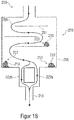
- Figure 8 shows such a refrigeration cycle 81 as is known in the prior art.
- the refrigeration circuit 81 has a condenser 82 and an evaporator 83. Between the condenser 82 and the evaporator 83 there is a local constriction 84a, 84b of the flow cross-section, which leads to a reduction in the fluid pressure and causes an increase in volume or expansion of the fluid flowing through.
- This local constriction 84a, 84b is functionally referred to as a throttle or expansion valve.
- a piece of tube with a very small inside diameter acts as an unregulated, non-adjustable expansion element, which is then typically referred to as a throttle capillary 84b.
- Inexpensive throttle capillaries are preferred for systems with low cooling capacity, such as household fridge-freezers.
- controllable expansion valves 84a are continuously variable valves which allow the fluid flowing through to be adjusted. These are preferred for systems with a higher cooling capacity.
- a solution is therefore not to use a continuously adjustable valve but a switching valve that is then completely open or closed at times, i.e. is operated in the sense of a pulse width modulation.
- this approach is rated as not so favorable in terms of energy and system behavior.
- An expansion valve for small cooling capacities can also be called a micro-expansion valve.
- the DE 10 2010 042 265 A1 describes a multi-way valve for switching between two channels.
- rigid perforated diaphragms or adjustable slit diaphragms are used as throttles, which is why this form of valve is also referred to as diaphragm valve.
- the DE 10 2010 042265 A1 a valve for reducing a pressure of a fluid flowing through the expansion valve along a fluid flow path, the valve comprising: at least one fluid inlet and at least one fluid outlet, a first valve element with at least a first channel structure, a second valve element with at least a second channel structure and a third channel structure , wherein the first valve element and the second valve element are movable relative to one another, wherein in a first position of the valve elements the first channel structure and the second channel structure are aligned with one another and form a first fluid flow path with a first flow resistance between the fluid inlet and the fluid outlet, and wherein in one second position of the valve elements, the first channel structure and the third channel structure are aligned with one another and a second fluid flow path with a second flow resistance different from the first flow resistance and form between the fluid inlet and the fluid outlet.
- channels through which the fluid flows are known.
- the slowing down and thus the expansion of the fluid is mainly due to eddy currents caused at the edge of the diaphragm.
- An expansion valve with channels is for example in the DE 31 08 051 A1 suggested.
- An expansion valve that can be switched in discrete switching stages is described here.
- Several disks are placed one on top of the other, with radially extending channels being formed between the disks through which the fluid can flow.
- In the middle of the disks there is a piston which can be moved in the axial direction to allow the fluid to flow through the individual channels.
- this expansion valve has a complicated structure and a large axial overall height. For devices with low cooling capacities, at where there is usually only a very small amount of space available, this expansion valve is therefore less suitable.
- the fluid flowing through the expansion valve contains particles. These particles can clog the expansion valve or individual channels of the expansion valve, which in turn can lead to a (partial) failure of the expansion valve.
- the EP 3 124 837 A1 therefore suggests providing a circumferential groove with several shielding parts in the form of projections on a valve body.
- the production of the many individual projections is complex, however. Apart from this, it was already recognized in the publication itself that certain types of soiling, such as hair, for example, cannot be held back sufficiently well by these shielding parts. It is an object of the present invention to improve expansion valves with regard to the problems mentioned above.
- the expansion valve according to the invention is designed to reduce a pressure of a fluid flowing through the expansion valve along a fluid flow path.
- the expansion valve has, inter alia, at least one fluid inlet through which the fluid can flow into the expansion valve, and at least one fluid outlet through which the fluid can flow out of the expansion valve.
- the expansion valve also has a first valve element with at least one first channel structure.
- the expansion valve has a second valve element with at least a second channel structure and a third channel structure.
- the first valve element and the second valve element are movable relative to one another, wherein in a first position of the valve elements the first channel structure and the second channel structure are aligned with one another and form a first fluid flow path with a first flow resistance between the fluid inlet and the fluid outlet. In a second position of the valve elements, the first channel structure and the third channel structure are aligned with one another and form a second fluid flow path with a second flow resistance, different from the first flow resistance, between the fluid inlet and the fluid outlet.
- a flow resistance can, for example, consist of a length of the flow-through channel structure, the cross-section of the flow-through channel structure that is not necessarily uniform along the length of the flow-through, a change in the flow-through cross-section or the channel course, a geometric cross-sectional shape, a roughness of the surface of the walls of the flow-through channel structure, or Combination of these parameters result.
- the different flow resistances throttle the flow of the fluid to different degrees.
- the throttling effect can be adjusted by varying the aforementioned parameters.
- the expansion valve according to the invention can bring about a complete throttling in one switching position, so that the flow of the fluid is almost completely blocked from the fluid inlet to the fluid outlet.
- the expansion valve according to the invention cannot, for example, have any significant throttling in another switching position, so that the fluid can flow almost unimpeded from the fluid inlet to the fluid outlet.
- the expansion valve can provide any desired throttle stage, ie between complete blocking and complete flow-through. As mentioned above, this is possible by varying the channel structure parameters.
- the amount of pressure drop is determined by the throttle stages, ie by the flow resistance, of the individual channel structures.
- the invention thus creates the integration of different flow resistances together with a switchable distributor within a single expansion valve. This can considerably reduce the installation space required compared to distributor circuits with separate chokes or capillaries.
- the requirements placed on the required precision of the drive are significantly lower, which in turn significantly reduces the manufacturing costs.
- channel structures are described on the basis of two exemplary channel structures, namely a first channel structure 22a, 22b and a second channel structure 23a, 23b.
- Each channel structure 22a, 22b, 23a, 23b can have a section 22b, 23b extending radially (with respect to the axis of rotation).
- Each channel structure 22a, 22b, 23a, 23b can have an axially (with respect to the axis of rotation) extending section 22a, 23a.
- the respective axially extending section 22a, 23a and / or the respective radially extending section 22b, 23b can be straight or irregular, for example curved or in the form of one or more curves (see e.g. Figure 13 ), from a center of a valve element 10, 20 to an outside of the respective valve element 10, 20.
- Each of the channel structures 22a, 22b, 23a, 23b can provide a throttling function for throttling the fluid.
- the channel structures 22a, 22b, 23a, 23b can therefore also be referred to as throttle channel structures. Since, in particular, the radially extending sections 22b, 23b can provide different throttle stages, the radially extending sections 22b, 23b in particular are referred to as throttle channel structures in this document.
- fluid can mean both a liquid and a gas. Mixed forms of partially gaseous and liquid states of the fluid can also be meant here.
- the fluid can be present in all aggregate states that occur.
- the fluid can be in an essentially liquid aggregate state in the flow direction upstream of the expansion valve, while it can be in an essentially gaseous state in the flow direction after the expansion valve (possibly with a downstream evaporator).
- the fluid can be a refrigerant, e.g. R600a or R134a.
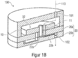
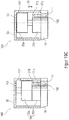
- the Figures 1A and 1B show a first embodiment of an expansion valve 100 according to the invention.
- the expansion valve 100 has at least one fluid inlet 101 and at least one fluid outlet 102.
- the expansion valve 100 also has a first valve element 10 with at least one first channel structure 11.
- the expansion valve 100 also has a second valve element 20.
- the second valve element 20, as shown here by way of example, can consist of two parts 20a, 20b. Further embodiments provide that the second valve element 20 is designed in one piece.
- the second valve element 20 has at least a second channel structure 22a, 22b and a third channel structure 23a, 23b.
- Channel structures in general, and the depicted channel structures 11, 22a, 22b, 23a, 23b in particular, are structures provided in the respective valve element 10, 20, e.g. in the form of recesses that provide a flow path for a fluid flowing through.
- the first valve element 10 and the second valve element 20 are movable relative to one another. As in particular in Figure 1B As can be seen, in a first position of the valve elements 10, 20 the first channel structure 11 and the second channel structure 22a, 22b are aligned with one another and form a first fluid flow path 110 with a first flow resistance between the fluid inlet 101 and the fluid outlet 102.
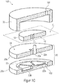
- the Figures 1C and 1D show a second position of the valve elements 10, 20.
- the first channel structure 11 and the third channel structure 23a, 23b are aligned with one another and form a second fluid flow path 111 with a second flow resistance between the Fluid inlet 101 and the fluid outlet 102.
- At least one section 22b of the second channel structure 22a, 22b also opens into the circumferential channel structure 55.
- the circumferential channel structure 55 connects the channel structures 22a, 22b, 23a, 23b formed in the second valve element 20 with one another and forms a common feed to the fluid outlet 102.
- the amount of the total flow resistance for the fluid flowing through can be composed of a) the flow resistance of the first channel structure 11 of the first valve element 10, b) the flow resistance of the respective channel structure 22a, 22b, 23a, 23b of the second valve element 20 and c) the flow resistance of the circumferential channel structure 55.
- the second valve element 20 can also, in addition to the second and third channel structures 22a, 22b; 23a, 23b, also further channel structures 24a, 24b; 25a, 25b. These are described in more detail below.
- the individual channel structures can have different, not necessarily constant, flow cross-sections along the channel length, i.e. a channel structure can have a variable flow cross section. According to conceivable embodiments of the invention, the flow cross-sections of the individual channel structures can either be constant or just variable.
- a variable flow cross section can be achieved, for example, in that the geometric cross section of the respective channel structure changes at least once over its channel length.
- a channel structure with a variable flow cross section can have a first location at a first point Flow cross-section and at a second point have a second flow cross-section different from the first flow cross-section.
- a channel structure can be designed in such a way that the flow cross section increases or decreases along the direction of fluid flow.
- the channel structure could have a first flow cross-section at the beginning and at the end and a second (smaller or larger) flow cross-section in between, e.g. in the form of a constriction and the like.
- the flow cross section of a channel structure can influence the flow rate of a fluid flowing through this channel structure. This means, for example, that with the same channel length, a smaller volume of a channel structure results in a smaller flow cross section of this channel structure, which opposes a greater flow resistance to the fluid flowing through, whereby the flow rate of the fluid can be throttled.
- channel structures are conceivable which have a round shape. These can be produced, for example, by means of drilling. However, it is also conceivable that the channel structures have a rectangular shape. These can be produced, for example, by means of milling. In principle, other geometric shapes of the channel structures are also conceivable, e.g. triangular, round, half-round, or polygonal. For example, a triangular-shaped channel structure can have a higher flow resistance than a square-shaped channel structure.
- different flow cross-sections oppose different flow resistances to the fluid and thus throttle the flow rate of the fluid to different degrees.
- channel structures with different flow cross-sections can also be referred to as different throttle stages for throttling the flow rate.
- the throttling also brings about a decrease in the pressure of the fluid flowing through, ie the pressure of the fluid at the fluid outlet 102 is lowered compared to the pressure of the fluid at the fluid inlet 101.
- the Expansion valve 100 relaxes the fluid. It can also, at least partially, evaporate.
- the individual channel structures can therefore be referred to as throttle stages, by means of which the expansion valve 100 according to the invention can throttle the flow rate or the mass flow of the fluid flowing through.
- the second channel structure 22a, 22b can have a first flow cross section
- the third channel structure 23a, 23b can have a second flow cross section that is different from the first flow cross section.
- the expansion valve 100 thus has at least two different throttle stages.
- the throttle stages can have throttle rates between almost 100% and almost 0%.
- the relative value of the throttling rates here relates to the throttling of the flow rate of the fluid between the fluid inlet 101 and the fluid outlet 102 based on a time period ⁇ t.
- a throttling rate of 100% means, for example, that the flow rate of the fluid from fluid inlet 101 to fluid outlet 102 is almost zero or equal to zero within this time period ⁇ t.
- the expansion valve 100 thus blocks the flow of the fluid.
- the expansion valve 100 can thus provide a “stop function” in which a flow of the fluid is stopped. Due to valve leaks which are known to the person skilled in the art and which often occur, the flow rate can only be almost at 0%, ie slightly above 0%. For example, a flow rate can be between 0% and 5% in the event of leaks that may occur.
- a throttling rate of almost 0% means that the flow of the fluid is almost not throttled, i.e. the flow rate of the fluid from fluid inlet 101 to fluid outlet 102 in the time period ⁇ t is almost 100%. Due to flow and friction losses within the channel structures through which the flow is flowing, the flow rate is usually only almost 100%, i.e. always slightly below 100%. For example, a flow rate can be between 95% and 100% here.
- the expansion valve 100 can thus provide an “open function” or also “free-flow function”, in which the fluid can flow through almost unhindered. In this case, there is therefore no significant throttling within the expansion valve 100.
- the expansion valve 100 has at least two throttle stages, i. the flow resistance of the first flow path in the first switching position differs from the flow resistance of the second flow path in the second switching position. At least one of the two flow resistances can be designed in such a way that the expansion valve 100 does not have any significant throttling in the respective switching position. That is to say, at least one of the two flow paths (first switching position or second switching position) forms an aforementioned "open function" or free-flow function ".
- Such an “open function” can be implemented, for example, in that the first and second channel structures 11; 22a, 22b or the first and third channel structures 11, which form the second fluid flow path; 23a, 23b as one through the first and second valve elements 10; 20 through opening, e.g. a bore of the same diameter, which opening has no significant restriction.
- the expansion valve 100 has a throttling rate of almost 0%, or can have a throttling rate between 0% and a maximum of 5%.
- a previously mentioned “stop function” can be implemented, for example, in that the first channel structure 11 in the first valve element 10 is not aligned with any of the channel structures 22a, 22b, 23a, 23b of the second valve element 20.
- This can be implemented, for example, in that the first valve element 10 is in a (not third switch position, which is e.g. between the first switch position ( Figure 1B ) and the second switch position ( Figure 1D ) can lie.
- the first channel structure 11 of the first valve element 10 thus no longer opens into a further channel structure in the second valve element 20 but directly on the surface 28 ( Figures 1A , 1D ) of the second valve element 20.
- the fluid is thus no longer conducted to the fluid outlet 102, ie the flow of the fluid is blocked or interrupted as a result.
- the first valve element 10 can be moved relative to the second valve element 20, for example by means of a stepping motor.
- One of the two valve elements 10, 20 is driven by means of the stepping motor and moved relative to the other of the two valve elements 10, 20.
- a transmission can be provided that reduces or translates the drive of the stepping motor accordingly.
- the stop function in the third switching position is between the first and the second switching position, this has particular advantages in terms of possible energy savings.
- an initial position of the valve element 10, 20 connected to the stepping motor is the third switching position.
- the stepper motor would not have to move the valve element 10, 20 all the way from the first switch position to the second switch position (or back), but in this case it is sufficient to move the valve element 10, 20 only from the third switch position to the first or to move the second switch position. Since the third switching position lies between the first and the second switching position, the stepper motor only has to cover half the distance.
- the first valve element 10 could be driven by the stepping motor.
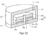
- An alternative Embodiment in which the second valve element 20 can be driven will be described below with reference to FIG Figures 2A and 2 B described.
- the second valve element 20 is designed in two parts in this exemplary embodiment, ie the second valve element has a first part 20b and a second part 20a.
- the first part 20b of the second valve element 20 here has at least one section 22b, 23b of the second and third channel structures 22a, 22b; 23a, 23b. That is to say, these sections 22b, 23b of the channel structures are formed in the first part 20b of the second valve element 20.
- the channel structures 22a, 22b; 23a, 23b and in particular their sections 22b, 23b are also referred to as throttle channel structures.
- the section 22b of the second channel structure 22a, 22b can also be referred to as a first throttle channel section 22b
- the section 23b of the third channel structure 23a, 23b can also be referred to as a second throttle channel section 23b.
- the first part 20b of the second valve element 20 can also have at least one fluid outlet 102.
- the throttle channel structures or sections 22b, 23b of the second and third channel structures are each connected to the fluid outlet 102 within the first part 20b of the second valve element 20, for example by means of the circumferential channel structure 55.
- a seal is advantageously arranged between the first part 20b of the second valve element 20 and the second part 20a of the second valve element 20, which fluidly seals the second and third channel structures 22b, 23b formed in the first part 20b of the second valve element 20 from one another.
- This can in particular be a Teflon seal, since it is particularly temperature-resistant, pressure-resistant and age-resistant.
- Sealing of the two parts 20a, 20b of the valve element 20 can also be achieved, for example, in that the two parts 20a, 20b are glued, screwed or welded to one another, for example by means of friction or laser welding.
- valve elements 10, 20 can in principle have various geometric shapes, i.e. the valve elements 10, 20 can, for example, be in the form of a cylinder, a cube, a sphere, a hemisphere, a pyramid, a prism and the like.
- the channel structures 11, 22a, 22b, 23a, 23b formed in the respective valve elements 10, 20 can extend at least in sections in a radial direction and / or at least in sections in an axial direction. If the two valve elements 10, 20 are rotatable relative to one another, for example, along an axis of rotation, an axial direction and a radial direction can relate to this axis of rotation.
- first valve element 10 and the second valve element 20 are each cylindrical valve elements, the first channel structure 11 in the first valve element 10 extending at least in sections in the axial and / or radial direction and / or where the second and third channel structure 22a, 22b; 23a, 23b in the second valve element 20 extend at least in sections 22b, 23b in the radial and / or axial direction.
- first valve element 10 and the second valve element 20 are each circular cylinder-shaped valve elements and the first valve element 10 is aligned concentrically with the second valve element 20 in the axial direction.
- first valve element 10 and the second valve element 20 can each be shown here by way of example as cylindrical valve elements.
- a cylinder by definition, is characterized by the fact that a flat curve in a plane is shifted by a fixed distance along a straight line that is not contained in this plane. Two corresponding points of the curves and the shifted curve are connected by a segment. The entirety of these parallel lines forms the associated cylinder surface.
- the curve or the resulting lateral surface can have any shape.
- the first valve element 10 and the second Valve elements 20 are each designed in the shape of a circular cylinder, the first valve element 10 in the axial direction 33 ( Figure 1A ) can be aligned concentrically with the second valve element 20.
- the first channel structure 11 in the first valve element 10 extends at least in sections in the axial direction 33 ( Figure 1A ).
- the first channel structure 11 extends completely through the first valve element 10. In terms of manufacturing technology, this can be achieved, for example, in that a bore is made in the axial direction 33 through the first valve element 10.
- the first channel structure 11 could extend in the radial direction 34 in the first valve element 10. This is in Figure 1A indicated by way of example with the first channel structure 11 ′ shown in broken lines. In terms of manufacturing technology, this can be achieved, for example, by making a bore in the radial direction 34 through the first valve element 10 in the same. It would also be conceivable that the radially running first channel structure 11 'shown in dashed lines is milled, sawn, lasered or cut from the underside 12 of the first valve element 10 into the same by means of a separating process and / or is embossed, shaped and formed by means of forming processes / or is produced directly with primary forming processes such as injection molding.
- the first channel structure 11 extends both in sections in the radial direction 34 and in sections in the axial direction 33.
- the second and third channel structures 22a, 22b, 23a, 23b in the second valve element 20 extend at least in sections in the radial direction 34 ( Figure 1A ). More precisely, the throttle channel structures or sections 22b, 23b of the channel structures 22a, 22b, 23a, 23b arranged in the first part 20b of the second valve element 20 extend at least in sections in the radial direction 34. In terms of manufacturing, this can be achieved, for example, by the throttle channel structures or The sections 22b, 23b are milled, sawn, lasered or cut from above into the second valve element 20 by means of separating processes and / or embossed, molded and / or produced directly with primary forming processes such as injection molding. These are relatively simple process steps that facilitate production and thus can significantly reduce unit costs.
- the second channel structure 22a, 22b and / or the third channel structure 23a, 23b extends at least in sections in the axial direction 33 through the second valve element 20 or the first part 20b of the second valve element 20.
- the second channel structure 22a, 22b could have a flow cross-section that differs from the third channel structure 23a, 23b.
- the first valve element 10 has a surface 12 facing the second valve element 20 ( Figures 1A and 1C ).
- the first valve element 10 and the second valve element 20 can be moved relative to one another, specifically in the depicted plane E 1 that runs parallel to this surface 12.
- the two valve elements 10, 20 can, for example, be movable in translation with respect to one another in this plane E 1 and thus displaced with respect to one another.
- the first valve element 10 and the second valve element 20 can be rotated relative to one another in the illustrated exemplary embodiments, so that a movement from the first position of the valve elements 10, 20 ( Figure 1B ) to the second position of the valve elements 10, 20 ( Figure 1D ) can be executed by means of a rotation of the first valve element 10 relative to the second valve element 20.
- first valve element 10 can be rotated relative to the second valve element 20, for example by means of a stepping motor, or the second valve element 20 can be rotated relative to the first valve element 10.
- the expansion valve 100 can have a cover 30.
- the cover 30 has a recess 31.
- the cover 30 is immovably connected to the second valve element 20.
- the first valve element 10 is arranged within this cover 30 or within the recess 31 so as to be movable relative to the second valve element 20, and thus also relative to the cover 30.
- the first valve element 10 can therefore be arranged in the expansion valve 100 in a movable manner, in particular in a rotationally movable manner.
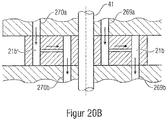
- the expansion valve 100 has an axis 41 which, for example, can be arranged non-rotatably on the second valve element 20 and / or on the cover 30.
- the first valve element 10 is movably, in particular rotatably, mounted on this axis 41 by means of a corresponding receptacle 42.
- the axis 41 is arranged centrally, ie in the center of the second valve element 20.
- the receptacle 42 of the first valve element 10 is also arranged centrally in the first valve element 10. That is, the first valve element 10 and the second valve element 20 are arranged concentrically about this axis 41. The first valve element 10 and the second valve element 20 are thus arranged concentrically with one another.
- the axis 41 is arranged off-center, ie not in the center of the second valve element 20.
- the first valve element 10 would then continue to be arranged concentrically to the axis 41.
- the first valve element 10 and the second valve element 20 would then, however, no longer be arranged concentrically but rather eccentrically to one another.
- Such an arrangement is for example in the Figures 9 and 10 which will be described in more detail later.
- the receptacle 42 in the first valve element 10 is eccentric, i. E. is not arranged in the center of the first valve element 10. Then the first valve element 10 would not be arranged concentrically but rather eccentrically with respect to the axis 41.
- an underside surface 27 of the cover 30 facing the second valve element 20 is coupled, for example glued, to a surface 28 of the second valve element 20.
- the cover 30 is arranged on the second valve element 20.
- the second valve element 20 can, so to speak, together with the cover 30 form a housing, in particular a fluid-tight housing.
- an inner wall 26 of the cover 30 to be coupled to a laterally circumferential outer wall 29a, 29b of the second valve element 20.
- the second valve element 20 would find space within the recess 31 of the cover 30.
- the second valve element 20, together with the cover 30, can form a housing, in particular a fluid-tight housing.
- An additional cover (not shown here) would then preferably be coupled to the underside surface 27 of the cover 30.
- the fluid inlet 101 can be arranged in the cover 30.
- a fluid inlet 101 ′ can be provided in the second valve element 20 and / or in the cover (not shown).
- this optional fluid inlet 101 ' is indicated with broken lines.
- the fluid inlet 101 can also be arranged laterally in the cover 30. However, there should be at least one fluid inlet that allows the Introduce fluid into the recess 31 of the cover 30 in order to direct the fluid to the channel structures of the two valve elements 10, 20.
- the first valve element 10 is arranged in front of the second valve element 20, based on the direction of flow of the fluid from the fluid inlet 101 to the fluid outlet 102.
- the fluid thus initially flows into the first valve element formed in the first valve element 10 Channel structure 11 and from there, depending on the switching position of the expansion valve 100, into at least one of the channel structures 22a, 22b, 23a, 23b arranged in the second valve element 20.
- the expansion valve 100 also has a cover 30, but with the difference that the cover 30 is immovably connected to the first valve element 10 and the second valve element 20 is arranged within the cover 30 so as to be movable relative to the first valve element 10.
- an axis 41 is non-rotatably arranged on the first valve element 10 and / or the housing 30.
- the second valve element 20 is also designed in two parts, the first part 20b and the second part 20a each being movably, in particular rotatably, mounted on this axis 41 by means of a corresponding receptacle 42.
- the axis 41 is arranged centrally, ie in the center of the first valve element 10.
- the receptacle 42 of the second valve element 20 is also arranged centrally in the second valve element 20. That is to say, the first valve element 10 and the second valve element 20 are arranged concentrically about this axis 41. The first valve element 10 and the second valve element 20 are thus arranged concentrically with one another.
- the axis 41 is arranged off-center, ie not in the center of the first valve element 10.
- the second valve element would then be 20 furthermore arranged concentrically to the axis 41.
- the first valve element 10 and the second valve element 20 would then, however, no longer be arranged concentrically but rather eccentrically to one another.
- the receptacle 42 in the second valve element 20 is off-center, i.e. is not arranged in the center of the second valve element 20. Then the second valve element 20 would not be arranged concentrically but eccentrically with respect to the axis 41.
- the second valve element 20 is arranged here in front of the first valve element 10, based on the direction of flow of the fluid from the fluid inlet 101 to the fluid outlet 102.
- the second valve element 20 is designed in two parts, a first part 20b of the second valve element 20 comprising the second and third channel structures 22a, 22b; 23a, 23b, and a second part 20a of the second valve element 20 has a closed cover of the second and third channel structures 22a, 22b; 23a, 23b forms.
- the channel structures 22a, 22b; 23a, 23b and in particular the radially extending sections 22b, 23b can also be referred to as throttle channel structures.
- the first channel structure 11 simultaneously forms the fluid outlet 102 of the expansion valve 100.
- Figure 2B shows a composite expansion valve 100 and the fluid flow path 112 resulting through the expansion valve 100.
- the fluid enters the expansion valve 100 through the fluid inlet 101, then flows through the channel structures 22a, 22b, 23a, 23b formed in the second valve element 20 and enters then out of the expansion valve 100 again through the fluid outlet 101, which is formed by the first channel structure 11 formed in the first valve element 10.
- the expansion valve 100 is in a first switching position. More precisely, the two valve elements 10, 20 are in a first position relative to one another, in this first position the first channel structure 11 and the second channel structure 22a, 22b are aligned with one another and a first fluid flow path 112 with a first flow resistance between the fluid inlet 101 and the fluid outlet 102 form.
- the second valve element 20 in contrast to that in FIG Figure 2B shown first switch position for example rotated by 180 °.
- first channel structure 11 and the third channel structure 23a, 23b would be aligned with one another and form a second fluid flow path with a second flow resistance different from the first flow resistance between the fluid inlet 101 and the fluid outlet 102.
- This individual circuit is distinguished, among other things, by the fact that in the first and second positions of the valve elements 10, 20 exactly one of the second and third channel structures 22a, 22b; 23a, 23b of the second valve element 20 is fluidically coupled to the fluid outlet 102 in order to form a single fluid flow path 111, 112 between the fluid inlet 101 and the fluid outlet 102.
- the second valve element 20 can also have further channel structures 24a, 24b, 25a, 25b in addition to the second and third channel structures 22a, 22b, 23a, 23b.
- the first valve element 10 has only one channel structure, namely the first channel structure 11.
- the two valve elements 10, 20 are moved relative to one another, for example by means of a stepper motor mentioned above, in such a way that the first channel structure 11 of the first valve element 10 only ever forms a single channel structure 22a, 22b, 23a, 23b, 24a, 24b, 25a, 25b of the second valve element 20 is aligned.
- the individual channel structures 22a, 22b, 23a, 23b, 24a, 24b, 25a, 25b of the second valve element 20 have different flow cross-sections.
- the throttling of the flow rate results on the one hand from the individual length and the individual flow cross-section of each individual channel structure 22a, 22b, 23a, 23b, 24a, 24b, 25a, 25b, which is not necessarily constant or geometrically variable over the channel length, and others by the length and the flow cross section of the common channel structure 55.
- Channel-specific fluid flow paths with individual throttling rates are thus formed.
- the individual channel structures can therefore be provided with a certain surface roughness. Tests have shown that when the surface roughness was set, differences in the throttling rate of up to 10% could be recognized in comparison to the fluidically smooth surface properties of the channel structures.
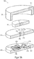
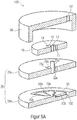
- FIG. 1A A series connection of the channel structures of the first embodiment ( Figures 1A to 1D ) is intended below with reference to the Figure 3A and 3B to be discribed.
- the series connection is characterized, among other things, in that the second channel structure 22a, 22b and the third channel structure 23a, 23b are connected to one another at least in sections 22b, 23b within the second valve element 20, i.e. at least the throttle channel structures 22b, 23b of the respective channel structures 22a, 22b ; 23a, 23b are connected to one another, wherein in the second position of the valve elements 10, 20 the second fluid flow path is composed of the second and the associated third channel structure 22b, 23b, and in particular of the respective throttle channel structures 22b, 23b, and the second fluid flow path has an overall flow resistance which is composed of the flow resistance of the second channel structure or throttle channel structure 22b and the flow resistance of the third channel structure or throttle channel structure 23b connected thereto.
- the second valve element 20 is again made in two parts.
- first part 20b several, here by way of example a total of five, different channel structures or throttle channel structures 22b, 23b, 24b, 25b, 26b are formed.
- the individual channel structures or throttle channel structures 22b, 23b, 24b, 25b, 26b are all fluidically connected to one another so that they form a long chain or a series connection of several channel structures or throttle channel structures.
- the expansion valve 100 has only one common fluid outlet 102, which is connected to the first or last channel structure or throttle channel structure 22b from the series connection.
- the fluid must travel paths of different lengths to the fluid outlet 102.
- the total flow resistance is composed of the individual flow resistances of the channel structures passed through.
- the individual channel structures, and in particular the throttle channel structures 22b, 23b, 24b, 25b, 26b can also have different flow cross-sections that are not necessarily constant or geometrically variable over the channel length.
- channel structures 22a, 23a, 24a, 25a, 26a which correspond to the channel structures or throttle channel structures 22b, 23b formed in the first part 20b of the second valve element 20 , 24b, 25b, 26b are aligned.
- the first valve element 10 is rotatable with respect to the second valve element 20 and has the first channel structure 11.
- the first channel structure 11 can now be optionally aligned in different switching stages to one of the channel structures 22a, 22b, 23a, 23b, 24a, 24b, 25a, 25b, 26a, 26b formed in the second valve element 20.
- a fluid flow path of different lengths is formed which the fluid flowing through must cover in order to reach the fluid outlet 102.
- FIG. 3B One of these several possible switch positions is exemplified in Figure 3B to see.
- the first valve element 10 is aligned with respect to the second valve element 20 such that the first channel structure 11 is aligned with the sixth channel structure 26a, 26b.
- the resulting fluid flow path is shown with the dashed arrow 121.
- the fluid thus enters the expansion valve 100 through the fluid inlet 101, then flows through the first channel structure 11, which is aligned with the sixth channel structure 26a, 26b, through all further channel structures or throttle channel structures 25b, 24b, 23b, and then afterwards Flow through the first channel structure or throttle channel structure 22b to open into the fluid outlet 102.
- This series connection is also characterized, inter alia, in that the second channel structure 22a, 22b and the third channel structure 23a, 23b are connected to one another at least in sections 22b, 23b within the second valve element 20, i.e. at least the throttle channel structures 22b, 23b are connected to one another, whereby In the second position of the valve elements 10, 20, the second fluid flow path is composed of the second and the third channel structure connected to it, and in particular the throttle channel structure 22b, 23b, and the second fluid flow path has an overall flow resistance that is derived from the flow resistance of the second channel structure, and in particular of the throttle channel structure 22b and the flow resistance of the third channel structure connected thereto, and in particular of the throttle channel structure 23b.
- the second valve element 20 is again made in two parts.
- first part 20b several, here by way of example a total of five, different channel structures 22a, 22b, 23a, 23b, 24a, 24b, 25a, 25b, 26a, 26b are formed.
- the individual channel structures 22a, 22b, 23a, 23b, 24a, 24b, 25a, 25b, 26a, 26b, or the sections 22b, 23b, 24b, 25b, 26b referred to as throttle channel structures are all fluidically connected to one another so that they form a long chain or form a series connection of several channel structures.
- each channel structure has a radial section 22b, 23b, 24b, 25b, 26b, also referred to as a throttle channel structure, and an axial section 22a, 23a, 24a, 25a, 26a.
- a throttle channel structure also referred to as a throttle channel structure
- an axial section 22a, 23a, 24a, 25a, 26a In the in Figure 4A In the sectional view shown, only the axial sections 22a and 26a of the second and sixth channel structure can be seen. The axial sections 23a, 24a, 25a of the other channel structures are covered in this sectional view and are therefore only indicated with broken lines.
- the expansion valve 100 again has only one common fluid outlet 102, which at the same time also forms the first channel structure 11 of the first valve element 10.
- the second valve element 20 is rotatable relative to the first valve element 10 and can now optionally be rotated into different switching stages, with a different one of the channel structures 22a, 22b, 23a, 23b, 24a, 24b, 25a, 25b, 26a, 26b of the second in each switching stage Valve element 20 is aligned with the first channel structure 11 of the first valve element 10. More precisely, depending on the switching stage, an axial section 22a, 23a, 24a, 25a, 26a of the respective channel structure of the second valve element 20 is aligned with the first channel structure 11 of the first valve element 10.
- the fluid always enters the second valve element 20 through the radial section or throttle channel structure 22b of the second channel structure 22.
- the fluid must pass through the corresponding further channel structures 23a, 23b, 24a, 24b, 25a, 25b, 26a, 26b in addition to the second channel structure 22a, 22b.
- the fluid must therefore travel paths of different lengths to the fluid outlet 102.
- a fluid flow path of different lengths is thus formed which the fluid flowing through must cover in order to reach the fluid outlet 102.
- the total flow resistance is composed of the individual flow resistances of the channel structures passed through.
- the individual channel structures 22a, 22b, 23a, 23b, 24a, 24b, 25a, 25b, 26a, 26b can also have different flow cross-sections that are not necessarily constant or geometrically variable over the channel length.
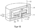
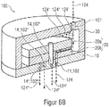
- FIG. 4B One of these several possible switch positions is exemplified in Figure 4B to see.
- the second valve element 11 is arranged opposite the first valve element 10 in such a way that the second channel structure 22a, 22b is aligned with the first channel structure 11.
- the resulting fluid flow path is shown with the dashed arrow 122.
- the fluid flows through the radial section or the throttle duct structure 22b of the second duct structure into the second valve element 20 and flows through the axial section 22a of the second duct structure 20 to the first duct structure 11, which is also the fluid outlet 102.
- the second valve element 20 would be, for example, by 180 ° compared to that in FIG Figure 4B shown switch position rotated.
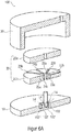
- expansion valve 100 according to the invention can also be used to connect the channel structures in parallel, as shown in FIGS Figures 5A to 6B is shown as an example.
- the parallel connection is characterized, among other things, by the fact that the first valve element 10 has at least one fourth channel structure 14, and in the first position of the valve elements 10, 20 the third channel structure 23a, 23b of the second valve element 20 and the fourth channel structure 14 of the first Valve elements 10 are aligned with one another and form a third fluid flow path with a third flow resistance between the fluid inlet 101 and the fluid outlet 102.
- the amount of the third flow resistance can differ from the amount of the first and / or second flow resistance. That is, the third fluid flow path can provide a third throttle stage.
- the first channel structure 11 of the first valve element 10 and the second channel structure 22a, 22b of the second valve element 20 are aligned with one another, and at the same time the second channel structure 14 of the first valve element 10 and the third channel structure 23a, 23b of the second valve element 20 aligned with one another.
- the first valve element 10 has at least one further channel structure 14.
- the first valve element 10 here even has three further channel structures, namely a seventh channel structure 14, an eighth channel structure 14 ′ and a ninth channel structure 14 ′′.
- the second valve element 20 corresponds essentially to that with reference to FIG Figures 1A to 1D described embodiment.
- the individual channel structures 11, 14, 14 ', 14 "of the first valve element 10 can be aligned with the channel structures, and in particular with the axial sections 22a, 23a, 24a, 25a, of the channel structures in the second valve element 20. This enables different switching positions , with a different number of the four channel structures 11, 14, 14 ', 14 "of the first valve element 10 being aligned with the four channel structures 22a, 23a, 24a, 25a of the second valve element 20, depending on the switching position.
- Figure 5B shows an example of a switching position in which all four channel structures 11, 14, 14 ', 14 "of the first valve element 10 are aligned with the four channel structures 22a, 23a, 24a, 25a of the second valve element 20.
- the resulting fluid flow is indicated by the arrow 123 is drawn.
- the fluid thus flows through all four channel structures 11, 14, 14 ', 14 "of the first valve element 10, as well as through all four channel structures 22a, 23a, 24a, 25a of the second valve element 20 aligned therewith.
- This is, so to speak, the largest switching stage , in which all channel structures are active at the same time. Accordingly, the flow rate of the fluid can be greatest in this switch position, since the fluid can flow through all channel structures simultaneously.
- the total flow resistance is again made up of the individual flow resistances of the respective channel structures passed through.
- the individual channel structures 22a, 22b, 23a, 23b, 24a, 24b, 25a, 25b, 26a, 26b also have different flow cross-sections that are not necessarily constant or geometrically variable over the channel length.
- a stop function could here, for example, by rotating the first valve element 10 by 180 ° compared to that in FIG Figure 5B switch position shown can be reached. None of the channel structures 11, 14, 14 ′, 14 ′′ of the first valve element 10 would be aligned with any of the channel structures 22a, 22b, 23a, 23b, 24a, 24b, 25a, 25b, 26a, 26b of the second valve element 20.
- the expansion valve 100 has precisely one fluid outlet 102 and the second and third channel structures 22a, 22b; 23a, 23b of the second valve element 20 can be fluidically coupled to this one fluid outlet 102. Even if not explicitly shown in the figures, it would also be possible for the expansion valves 100 according to the invention not to have exactly one, but at least one fluid outlet 102, i.e. the expansion valves 100 can also have a second, third, or any number of fluid outlets 102.
- the first valve element 10 has at least one further channel structure 14.
- the first valve element 10 here even has three further channel structures, namely a seventh channel structure 14, an eighth channel structure 14 ′ and a ninth channel structure 14 ′′.
- the second valve element 20 corresponds essentially to that with reference to FIG Figures 2A and 2 B described embodiment.
- the channel structures formed in the second valve element 20, namely a second channel structure 22a, 22b, a third channel structure 23a, 23b, a fourth channel structure 24a, 24b and a fifth channel structure 25a, 25b, have a radially extending section 22b, also referred to as a throttle channel structure , 23b, 24b, 25b, through which the fluid can flow into the second valve element 20, and an axial section 22a, 23a, 24a, 25a, which leads to at least one of the channel structures 11, 14, 14 'arranged in the first valve element 10 .14 "can be aligned.
- Figure 6B shows the expansion valve 100 by way of example in FIG Figure 6A better visible switching position in which all four channel structures 22a, 23a, 24a, 25a of the second valve element 20 are aligned with the four channel structures 11, 14, 14 ', 14 ′′ of the first valve element 10.
- the resulting fluid flow is indicated by arrows 124 , 124 ', 124 ", 124'”.
- the fluid exits the expansion valve 100 through all activated fluid outlets 11, 14, 14 ', 14 ", which in turn is represented by the arrows 124', 124", 124 '"indicating the fluid flow is.
- the fluid first flows into the expansion valve 100 through the fluid inlet 101. It is then distributed over all four channel structures 22a, 22b, 23a, 23b, 24a, 24b, 25a, 25b in the second valve element 20, which is shown by the arrows 124, 124 ', 124 ", 124"'. That is, a first part 124 of the fluid flow enters the first channel structure 22a, 22b, a second part 124 'of the fluid flow enters the second channel structure 23a, 23b, a third part 124 "of the fluid flow enters the third channel structure 24a, 24b and a fourth portion 124 '"of the fluid flow enters the fourth channel structure 25a, 25b.
- the fluid thus flows through all four throttle channel structures or radial sections 22b, 23b, 24b, 25b of the four channel structures of the second valve element 20 into the second valve element 20.
- the fluid then flows into the axial sections 22a, 23a, 24a, 25a of the channel structures of the second valve element 20, which in the switching position shown are all aligned with a respective channel structure 11, 14, 14 ', 14 "of the first valve element 10.
- the fluid leaves the expansion valve 100 through the respective channel structures 11, 14, 14 ', 14 "of the first valve element 10, since these simultaneously form the multiple fluid outlets 102, 102', 102", 102 '"of the expansion valve.
- the total flow resistance is again made up of the individual flow resistances of the respective channel structures through which flow occurs.
- the individual channel structures 22a, 22b, 23a, 23b, 24a, 24b, 25a, 25b, 26a, 26b can also have different flow cross-sections that are not necessarily constant or geometrically variable over the channel length.
- a stop function could here, for example, by rotating the second valve element 20 by 180 ° compared to that in FIG Figure 6A switch position shown can be reached. None of the channel structures 22a, 22b, 23a, 23b, 24a, 24b, 25a, 25b, 26a, 26b of the second valve element 20 would be aligned with any of the channel structures 11, 14, 14 ', 14 "of the first valve element 10.
- the individual positions of the valve elements 10, 20 can be switched to one another in discrete steps.
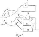
- the expansion valve 100 could in principle also have a combination of a parallel connection with a series connection. Such a case is exemplified in the form of a schematic block diagram in FIG Figure 7 shown.
- the fluid flow running through the expansion valve 100 first leads through a channel structure 22 with a first flow resistance 71 and then in a parallel connection of channel structures 23, 24, 25 with a second flow resistance 72, a third flow resistance 73 and a fourth flow resistance 74.
- the flow resistance 71, 72, 73, 74 can be the same size or different.
- the channel structure 22 is connected in series with the parallel connection of the channel structures 23, 24, 25.
- the total flow resistance is again made up of the individual flow resistances of the respective channel structures 22, 23, 24, 25 through which flow occurs.
- the expansion valve 100 can be made of different materials, i. the expansion valve 100 can, for example, comprise metal, plastic, glass or ceramic.
- the individual parts, i.e. the first valve element 10, the second valve element 20 and the cover 30 can be screwed, clamped, glued or welded together.
- the channel structures can be microchannel structures. These microchannel structures can flow cross-sections in Area of square millimeters or square micrometers.
- the microchannel structures can be introduced into the respective valve element 10, 20, for example, by means of precision milling, or they can be produced by means of injection molding or embossing. It is also conceivable that the microchannel structures are introduced into the respective valve element 10, 20 using etching processes, for example when the respective valve element 10, 20 contains silicon or other materials that are reactive to etchant.
- the expansion valve 100 can be arranged, for example, in a refrigeration circuit between two heat exchangers.
- Such heat exchangers can, for example, be so-called evaporators or condensers.
- the expansion valve can for example be arranged between such an evaporator and a condenser.
- the expansion valve 100 can also be arranged between at least two evaporators, which are followed by at least one condenser.
- a household refrigerator in particular a refrigerator and / or freezer, with an expansion valve 100 according to the invention is conceivable.
- This preferably means refrigerators and / or freezers with a cooling capacity of less than 1000 watts.
- these can be refrigerators, freezers, or fridge-freezers.
- the expansion valve 100 according to the invention can be used in any type of refrigeration machine, in particular in compression refrigeration machines.
- the expansion valve 100 can preferably be used in refrigerating machines with mass flows of less than 3 kg / h.
- the expansion valve 100 according to the invention can also have means for binding moisture.
- Zeolite for example, can be used as such a means for binding moisture.
- the zeolite is preferably used in the form of bulk material or as a sintered material.
- the means for binding moisture can, for example, be arranged upstream of the fluid inlet 101 in the direction of fluid flow.
- the means for binding moisture are preferably arranged between the fluid inlet 101 and the first or second valve element 10, 20.
- the means for binding moisture can for example be arranged in the recess 31 of the cover 30.
- the means for binding moisture can also be arranged in one or more of the channel structures 11, 14, 22, 23, 24, 25, 26 of the first and / or second valve element 10, 20, in particular when the means for binding Moisture in the form of loose bulk material.
- the means for binding moisture are advantageous in order to bind any moisture that may be present in the refrigerant and thus prevent unwanted ice formation elsewhere in the refrigeration circuit.
- the expansion valve 100 according to the invention can have at least one particle filter.
- the particle filter is advantageously arranged in the direction of flow after the means for binding moisture.
- the particle filter preferably filters particles which originate from the means for binding moisture, for example zeolite particles.
- the expansion valve 100 can, according to a further aspect of the invention, for example have a retaining element.
- a particulate filter just mentioned is one of several examples of such a retaining element. How such retaining elements for use on an expansion valve 100 according to the invention can look like, should be based on the following exemplary embodiments with reference to FIG Figures 11 to 21d are described in more detail.
- a retaining element can generally always be arranged along a fluid flow path flowing through the expansion valve 100 at any point in or on the expansion valve 100.
- Several retaining elements are also conceivable.
- Several retaining elements can be provided, with at least one retaining element being provided per throttle channel structure.
- a central retaining element can be provided with which at least two throttle duct structures are fluidically coupled.
- a retaining element which has at least two filter channel structures.
- the filter channel structures can for example be formed in the first valve element 10 his.
- the filter channel structures can be formed in the second valve element 20, or at least in a part 20a, 20b of the two-part second valve element 20.
- channel structures such as the filter channel structures, throttle channel structures and collecting channel structures described below
- the channel structures and in particular the filter channel structures 222 and / or the throttle channel structures 21b to 27b in the in Figure 2A depicted first part 20b of the two-part second valve element 20 are formed.
- the following Figures 11 and 13 to 17 thus show a top view of the in Figure 2A depicted first part 20b of the two-part second valve element 20.
- the filter channel structures 222 and / or the throttle channel structures 21b to 27b in the second part 20a of the second valve element 20 and / or in the first valve element 10 are trained.
- all of the channel structures described below can also be designed in the form of a throttle bore.
- a throttle bore can be designed, for example, as an axial bore extending through the first part 20b and / or the second part 20a of the second valve element 20 and / or through the first valve element 10.
- the axial direction 33 relates to the axis of rotation.
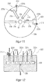
- FIG 11 shows Figure 11 a top view of the in Figure 2A
- the illustrated first part 20b of the two-part second valve element 20 The individual channel structures 22a, 22b; 23a, 23b; 24a, 24b; 25a, 25b, which are formed along the top of the first part 20b of the two-part second valve element 20 facing the viewer.
- the channel structures formed in the first part 20b of the second valve element 20 are used as a second channel structure 22a, 22b, a third channel structure 23a, 23b, and a fourth channel structure 24a, 24b and denotes a fifth channel structure 25a, 25b.
- the channel structures in this exemplary embodiment can each have an axially running section 22a, 23a, 24a, 25a and a radially running section 22b, 23b, 24b, 25b.
- the radial sections 22b, 23, 24b, 25b contribute the main part to the throttling of a fluid flowing through the channel structures.
- the radial sections are therefore also referred to as throttle channel structures 22b, 23b, 24b, 25b.
- the throttle channel structures 22b, 23b, 24b, 25b can have different flow resistances, for example due to different cross-sections.
- the second channel structure 22a, 22b can thus be a first throttle channel structure 22b with a specific cross section with any geometric shape, e.g. triangular, square, polygonal, trapezoidal, round, semicircular, etc., and the third channel structure 23a, 23b can have a second throttle channel structure 23b, which also has a certain cross-section with any shape.
- the cross section of the first throttle channel structure 22b can be the same as the cross section of the second throttle channel structure 23b.
- the respective cross-sections of the first throttle channel structure 22b and of the second throttle channel structure 23b can also differ from one another.
- the throttle channel structures 22b, 23b can have different flow resistances.
- the flow resistance can, for example, consist of a length of the flow-through throttle channel structure 22b, 23b, the cross-section of the flow-through throttle channel structure 22b, 23b that is not necessarily uniform along the channel length, a change in the flow-through cross-section or the channel course, a geometric cross-sectional shape, a roughness of the surface of the walls flow through throttle channel structure 22b, 23b, or result from a combination of these parameters.
- the different flow resistances throttle the flow of the fluid to different degrees.
- the throttling effect can be adjusted by varying the aforementioned parameters.
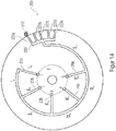
- expansion valve according to the invention, or in this exemplary embodiment the one in Figure 11 depicted second valve element 20, at least one retaining element 200 which is designed to retain a particle 210 located in the fluid flowing through the expansion valve 100.
- a first retaining element 200 is arranged in the region of the first throttle channel structure 22b.
- a second retaining element 200 ′ is arranged in the region of the fourth throttle channel structure 25b. According to the invention, however, one retaining element 200 is already sufficient.
- Each of the two retaining elements 200, 200 'shown here has at least two filter channel structures 222a, 222b; 225a, 225b, which are each fluidically coupled to at least one throttle channel structure 22b, 25b.
- the first retaining element 200 is connected to the first throttle channel structure 22b
- the second retaining element 200 ′ is connected to the fourth throttle channel structure 25b and is fluidically coupled.
- the filter channel structures 222a, 222b; 225a, 225b can, for example, be introduced into the second valve element 20 in the same way as the throttle channel structures 22b, 23b, 24b, 25b, for example by means of milling, laser cutting and the like.
- the filter channel structures 222a, 222b of the first retaining element 200 are fluidically coupled to the first throttle channel structure 22b. That is to say that a fluid exchange between the respective channel structures 222a, 222b; 22b is possible.
- the filter channel structures 225a, 225b of the second retaining element 200 ′ are fluidically coupled to the fourth throttle channel structure 25b. That is, a fluid exchange between the respective channel structures 225a, 225b; 25b is possible.
- the filter channel structures 222a, 222b; 225a, 225b are also led to the edge of the first part 20b of the second valve element 20 and provide a fluid inlet there. That is, fluid can there into the respective filter channel structures 222a, 222b; 225a, 225b flow in. The fluid that has flowed in then flows along the respective filter channel structure 222a, 222b; 225a, 225b into the respective throttle channel structure 22b, 25b which is fluidically coupled therewith.
- the filter channel structures 222a, 222b; 225a, 225b are designed to retain a particle 210.
- a particle 210 ′ clogs one of the two filter channel structures 225a, 225b of the second retaining element 200 ′ fluidically coupled to the fourth throttle channel structure 25b.
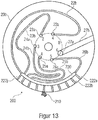
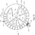
- FIG. 12 shows schematically a retaining element 200 with six filter channel structures 222a to 222f, all of which are fluidically coupled to the throttle channel structure 22b.
- the filter channel structures 222a to 222f are also arranged upstream of the throttle channel structure 22b in the direction of fluid flow.
- the filter channel structures 222a to 222f can therefore hold back a particle 210 before this particle 210 can penetrate into the respective throttle channel structure 22b and block it.
- the individual filter channel structures 222a to 222f can all have the same cross section or, as shown, different cross sections from one another.
- the cross section of the filter channel structures 222a to 222f is smaller than or equal to the cross section of the throttle channel structure 22b fluidically coupled therewith.
- the filter channel structures 222a to 222f can hold back a particle 210 that would be large enough to penetrate into the respective throttle channel structure 22b and block it.
- the cross section is at least the cross section of the fluid inlet surface into the respective channel structure 22b; 222a, 222b meant. That is, the cross section or the opening at the beginning of the channel structure 22b; 222a, 222b, through which the fluid into the respective channel structure 22b; 222a, 222b occurs.
- At least one filter channel structure 222a, 222b and at least one throttle channel structure 22b each have an angular cross section, and at least one side of the angular filter channel structure 222a, 222b can be smaller than or equal to a shortest side of the angular throttle channel structure 22b.
- the filter channel structure 222a, 222b could, for example, have a cross-section with dimensions of 40 ⁇ 40, around the top to be able to guarantee the retention or filter function described.
- the filter channel structure 222a, 222b could, however, also have a cross section with dimensions of 100 ⁇ 30 in order to be able to ensure the retention or filter function described above.
- at least one side of the angular filter channel structure 222a, 222b is therefore smaller than or the same size as a shortest side of the angular throttle channel structure 22b.
- At least one filter channel structure 222a, 222b and at least one throttle channel structure 22b could each have a round cross section, the cross section of the round filter channel structure 222a, 222b being smaller than the cross section of the round throttle channel structure 22b in order to achieve the above-described retention or retention structure. To be able to guarantee filter function.
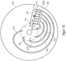
- a collecting channel structure 230 can be arranged between the filter channel structures 222a to 222f and the throttle channel structure 22b fluidically coupled therewith.
- This collecting channel structure 230 can be fluidically coupled to the filter channel structures 222a to 222f and to at least one throttle channel structure 22b, so that a fluid flowing in through at least one filter channel structure 222a to 222f is collected in the collecting channel structure 230 and passed on into the at least one throttle channel structure 22b.
- the fluid thus flows into the filter channel structures 222a to 222f in the direction of the arrow shown. Since all filter channel structures 222a to 222f are fluidly coupled to the collecting channel structure 230, the fluid then flows further into this collecting channel structure 230 and is collected there. The fluid that has collected in the collecting duct structure 230 then also flows further in the direction of the arrow into the respective throttle duct structure 22b which is fluidically coupled to the collecting duct structure 230.
- the retaining element 200, 200 'shown can be arranged individually for each channel. That is, in each case one throttle channel structure 22b, 23b can be connected or fluidically coupled to one retaining element 200, 200 '.
- a central retaining element 200 is provided, which is connected or fluidically coupled to a plurality of throttle channel structures.
- at least two throttle channel structures 22b, 23b can be arranged directly on the collecting channel structure 230 and fluidically coupled to the collecting channel structure 230.
- a retaining element 200 is shown here, which has a plurality of filter channel structures 222a to 222j. Two or more, and preferably all, filter channel structures 222a to 222j are fluidically coupled to the collecting channel structure 230.
- the collecting channel structure 230 is in turn fluidically coupled to at least two, and preferably all, throttle channel structures 22b, 23b, 24b, 25b, 26b.
- the retaining element 200 is arranged upstream of the respective throttle channel structures 22b, 23b, 24b, 25b, 26b in the fluid flow direction in order to prevent a particle 210 from penetrating into the valve element 20 and clogging the throttle channel structures 22b, 23b, 24b, 25b, 26b.
- a throttle channel structure 27b can have a larger cross section than the other throttle channel structures 22b, 23b, 24b, 25b, 26b.
- the one throttle channel structure 27b with the largest cross section of all throttle channel structures 22b, 23b, 24b, 25b, 26b is not fluidically coupled to the collecting channel structure 230 here.
- the throttle channel structure 27b can also be implemented by a channel structure in the valve element 20a, for example by a bore that is implemented by continuing the bore 27a through the valve element 20a.
- this one throttle channel structure 27b with the largest cross section of all throttle channel structures 22b, 23b, 24b, 25b, 26b can provide an "open" function mentioned at the beginning.
- This one throttle channel structure 27b with the largest cross section of all throttle channel structures 22b, 23b, 24b, 25b, 26b here has almost no throttling, i.e. the fluid flowing through can flow through this one throttle channel structure 27 almost unhindered or unthrottled.
- a connecting channel structure segment V a may be disposed between at least one throttle channel structure 25b (V b) and the collecting channel structure 230 that connects said at least one throttle channel structure 25b (V b) and the collecting channel structure 230 with one another and fluidically coupled to each other.
- a central retaining element 200 is also provided, the central retaining element 200 having a plurality of filter channel structures 222a to 222e which open into a collecting channel structure 230.
- At least one second throttle channel structure 24b (IV b ) is also connected to the connecting channel structure segment V a and fluidically coupled, specifically by means of a further channel structure segment IV a .
- the connecting channel structure segment V a which connects the collecting channel structure 230 to the individual throttle channel structures 21b to 25b (I b to V b ) can, if necessary, cause a throttling of the fluid flowing through.
- the further channel structure segments I a to IV a can also cause a throttling of the fluid flowing through
- throttle channel structure with the largest cross section of all throttle channel structures I b to V b is not fluidically coupled to the collecting channel structure 230.
- throttle channel structure 26b with the largest cross section of all throttle channel structures 22b, 23b, 24b, 25b, 26b can be fluidically coupled not only to the collecting channel structure 230, but also to the collecting channel structure 230 at the same time form themselves, the filter channel structures 222a to 222u opening into this collecting channel structure 230.
- the collecting channel structure 230 is therefore directly connected and fluidically coupled to that throttle channel structure 26b with the largest cross section of all throttle channel structures 22b, 23b, 24b, 25b, 26b.
- the collecting channel structure 230 and the throttle channel structure 26b can here have the same cross section.
- At least two filter channel structures 222a, 222b and at least two throttle channel structures 22b, 23b are connected and fluidically coupled directly to the throttle channel structure 26b, which at the same time also forms the collecting channel structure 230.
- all filter channel structures 222a to 222u and all throttle channel structures 22b, 23b, 24b, 25b are connected and fluidically coupled directly to throttle channel structure 26b, which at the same time also forms collecting channel structure 230.
- a particle 210 clogs a filter channel structure 222r
- the fluid can flow through all the other non-clogged filter channel structures 222a to 222u into the throttle channel structure 26b or the collecting channel structure 230 and from there to the respective throttle channel structure 22b, 23b, 24b, 25b, 26b continue to flow.
- the collecting duct structure 230 was designed in the shape of an arc in the second valve element 20.
- the collecting channel structure 230 has, for example, in FIG Figure 15 is shown has a radius R S which is smaller than the radius R V of the second valve element 20.
- the filter channel structures 222a to 222u fluidly coupled to the collecting channel structure 230 can be arranged to run radially outward starting from the collecting channel structure 230, for example in FIG Figures 13 and 15th is shown.
- the filter channel structures 222a to 222u can also be arranged to run axially outward starting from the collecting channel structure 230, for example in the form of axial bores which open into the collecting channel structure 230.
- the filter channel structures 222a to 222u in the second valve element 20 can define an opening to the environment through which the fluid can flow into the respective filter channel structure 222a to 222u. From there, the fluid flows into the collecting channel structure 230 and from there then in turn into the respective throttle channel structures 22b, 23b, 24b, 25b, 26b.
- the throttle channel structures 22b, to 27b were all arranged in the fluid flow direction after the filter channel structures 222a to 222u, i.e. the fluid first flows into the filter channel structures 222a to 222u and then into the throttle channel structures 22b to 27b.
- Figure 16 shows a further embodiment, according to which that throttle channel structure 26b with the largest cross section of all throttle channel structures 22b, 23b, 24b, 25b, 26b is connected to the filter channel structures 222a to 222g and fluidically coupled, this one throttle channel structure 26b arranged in the fluid flow direction in front of the filter channel structures 222a to 222g is.
- the filter channel structures 222a to 222g can also be fluidically coupled to a channel structure in valve element 20a, for example a bore that is implemented by continuing the bore 26a through valve element 20a.
- the fluid first flows into the throttle channel structure 26b with the largest cross section, before the fluid then flows to the filter channel structures 222a to 222g and from there to the individual remaining throttle channel structures 21b, 22b, 23b, 24b, 25b.
- a particle 210 which has been washed away is thereby passed through the fluid outlet side, e.g. axially extending channel structure 26a to the fluid outlet 102 and thus conveyed out of the expansion valve 100.
- Figure 17 shows a further exemplary embodiment of an expansion valve 100 according to the invention.
- FIG first part 20b of the two-part second valve element 20 shown in the top right figure.
- a side view of the first part 20b of the two-part second valve element 20 can be seen.
- the second part 20a of the two-part second valve element 20 is shown schematically in plan view.
- a side view of the second part 20a of the two-part second valve element 20 can be seen in the illustration below on the left.
- the expansion valve 100 has a bypass channel structure 223.
- the bypass channel structure 223 can be formed, for example, in the second part 20a of the two-part second valve element 20, preferably on the side facing the first part 20b.
- the bypass channel structure 223 can, however, also be formed in the first valve element 10, for example.
- the bypass channel structure 223 forms a bypass in the fluid flow path for one or more throttle channel structures 21b, 22b, 23b. That is, the bypass channel structure 223 enables fluid to flow through the bypass if, for example, a throttle channel structure 21b, 22b, 23b is clogged by a particle 210 or the like.
- the bypass channel structure 223 can be fluidically coupled to at least one fluid inlet section 224 of at least one throttle channel structure 21b, so that when the bypass channel structure 223 is fluidically coupled to this at least one throttle channel structure 21b, a particle adhering to this fluid inlet section 224 210 can be removed through the bypass channel structure 223.
- the fluid inlet section 224 is that section of the throttle channel structure 21b through which the fluid flows into the throttle channel structure 21b.
- the fluid inlet section 224 of a throttle channel structure 21b, 22b, 23b is that section which is open to the environment and enables the fluid to enter the throttle channel structure 21b, 22b, 23b. It is, so to speak, the opening through which the fluid enters the respective throttle channel structure 21b, 22b, 23b.
- bypass channel structure 223 has a larger cross section than the throttle channel structures 21b, 22b, 23b.
- the particle 210 shown here has clogged the fluid inlet section 224 of the throttle channel structure 21b.
- the bypass channel structure 223 is arranged opposite the clogged throttle channel structure 21b in such a way that the bypass channel structure 223 is at least opposite the clogged fluid inlet section 224 of the throttle channel structure 21b.
- the bypass channel structure 223 thus forms a fluid flow path 225 from the fluid inlet section 224 of the clogged throttle channel structure 21b, along the bypass channel structure 223, to one end 226 of the bypass channel structure 223.
- This said end 226 of the bypass channel structure 223 can be, for example, an opening to the environment through which the entrained Particles 210 can be flushed out or removed.
- the end 226 of the bypass channel structure 223 can, however, also open into the fluid outlet 102 of the expansion valve 100 in order to convey the entrained particle 210 out of the expansion valve 100.
- the bypass channel structure 223 in the illustrated embodiment is fluidically coupled to a fluid outlet section 227 of the at least one throttle channel structure 21b.
- the fluid outlet section 227 of the respective throttle channel structure 21b, 22b, 23b can, for example, be the, for example axially extending, channel structure section 21a, 22a, 23a of the respective channel structure 21a, 21b; 22a, 22b; 23a, 23b. Since this fluid outlet section 227 is fluidically coupled to the fluid outlet 102 of the expansion valve 100, the bypass channel structure 223 can guide the fluid in this embodiment directly to the fluid outlet 102 of the expansion valve 100. An entrained particle 210 is thus washed out through the fluid outlet 102.
- the blocked throttle channel structure 21b mentioned here by way of example is therefore on the input side, i.e. at its fluid inlet section 224, and optionally also on the outlet side, i.e. at its fluid outlet section 227, can be fluidically coupled to the bypass channel structure 223.
- bypass channel structure 223 could come to overlap at least at the fluid inlet section 224 of a throttle channel structure 21b with this fluid inlet section 224.
- Bypass channel structure 223 also come to overlap at least at the fluid outlet section 227 of a throttle channel structure 21b with this same fluid outlet section 227.
- bypass channel structure 223 overlaps the throttle channel structure 21b over the entire length, this corresponds to a temporary increase in the effective cross section of the respective throttle channel structure 21b.
- the at least one throttle channel structure 21b can optionally have, at least in sections, a shape that widens towards the bypass channel structure 223.
- the figure at the top left in Figure 17 an enlarged illustration of the throttle channel structure 21b.
- the throttle channel structure 21b has a trapezoidal shape which widens towards the bypass channel structure 223.
- the two parts 20a, 20b of the two-part second valve element 20 are, as indicated by the arrow 170, placed one on top of the other.
- the bypass channel structure 223 and the throttle channel structure 21b are thus arranged opposite one another and the throttle channel structure 21b widens towards the bypass channel structure 223.
- the expansion valve 100 is a means 240 ( Figure 15 ) for releasing and / or removing a particle adhering to the retaining element 200, the means 240 for releasing and / or removing a particle having a mechanical stripping device 241 which can be brought into contact with the retaining element 200 and is movable relative to the retaining element 200 , and wherein the stripping device 241 is designed to mechanically remove a particle 210 adhering to the retaining element 200 when the retaining element 200 is moved relative to the stripping device 241.
- the means 240 for loosening and / or removing a particle here has a mechanical stripping device 241 which, in terms of its function, is roughly comparable to a broom.
- the stripping device 241 is here in contact with the circumference of the first part 20b of the two-part valve element 20 and is attached in a stationary manner. When the valve element 20 moves past the wiper device 241, then a valve element 20 becomes adhering particles 210 are stripped from the valve element 20 by means of the stripping device 241.
- the retaining element 200 has been described by way of example in the form of the filter channel structures 222. In principle, however, it is of course conceivable that the retaining element 200 has a perforated plate and / or sintered material and / or a fabric structure and / or a network structure and / or an open-pored sponge structure and / or loose bulk material and / or water-binding material.
- the retaining element 200 can bring about a fixed flow resistance for the fluid flow flowing through the retaining element 200. That is to say, the retaining element 200 itself can already provide a throttle function. In this case, the amount of this flow resistance can, for example, be at most as great as is necessary for a smallest throttle stage.
- the retaining element 200 can be designed to throttle the fluid flow flowing through the retaining element 200 by 10% or less, preferably by 20% or less, and more preferably by 30% or less. That is, the restraint element 200 offers a fixed restriction, for example 30% or less, based on the fluid flow before and after the restraint element 200.
- a retaining element 200 can also throttle the fluid flow to almost 100% in front of each throttle channel structure 21b, 22b, 23b, the respective throttle channel structure 21b, 22b, 23b not having to provide any further throttling.
- the retaining element 200 can have a means for reducing the flow velocity of a fluid flow flowing along one of the fluid flow paths, so that a settling area is formed in the respective fluid flow path, in which particles which have penetrated can settle.
- Such a means for reducing the flow velocity can have at least one baffle wall and / or an expansion space and / or a section with a cross-section that is larger than that of the throttle channel structure 21b, 22b, 23b.
- Figure 18 an example of a retaining element 200 which has such a means 250 for reducing the flow velocity.
- the means 250 for reducing the flow velocity has an expansion space 255 or a section with a cross section that is larger than that of the throttle channel structure 21b.
- the flow velocity at the end of the installation space extension 255 can have decreased in such a way that a settling area 252 for the particles 210 is formed there.
- baffle plates 251 can be arranged in the installation space extension 255.
- settling areas 253 can form, in which particles 210 can settle.
- the baffle plates 251 can, however, also be arranged in a throttle channel structure 21b to 27b or in a filter channel structure 222a to 222u, i.e. the combination of the installation space extension 255 with the baffle plates 251 is optional.
- the retaining element 200 in the illustrated embodiment also has a filter channel structure 222a, 222b described above.
- the retaining element 200 only has the means 250 for reducing the flow velocity, ie without a combination with an additional filter channel structure 222a, 222b.
- the filter channel structures 222a, 222b are arranged in the fluid flow direction between the means 250 for reducing the flow velocity and the respective throttle channel structure 21b.
- the direction of fluid flow resulting in this exemplary embodiment of a retaining element 200 is indicated by arrow 258.
- the fluid therefore initially flows into the installation space extension 250. If the previously mentioned baffle plates 251 are present, the fluid flows past these baffle plates 251, and settling areas 253 for particles 210 may form in the area of these baffle plates 251.
- the fluid then flows on into the filter channel structures 222a, 222b directly connected to it and fluidically coupled therewith.
- filters 222a, 222b By means of these filter channel structures 222a, 222b, particles 210 can likewise be removed in the manner described above be held back.
- the fluid then flows into the respective throttle channel structure 21b which is connected and fluidically coupled.
- a collecting channel structure 230 is arranged between the filter channel structures 222a, 222b and the throttle channel structure 21b.
- the means 250 for reducing the flow velocity is preferably fluidically coupled to at least one throttle channel structure 21b in order to keep particles 210 away from this throttle channel structure 21b.
- a settling region 252 can form in the means 250 for reducing the flow velocity. It would be conceivable here for the settling area 252 to be arranged in such a way that a particle adhering to the retaining element 200 when there is an existing fluid flow settles into the settling area 252 due to gravity when the fluid flow decreases. Such a case would be conceivable, for example, if the Figure 18 would be rotated by 180 ° and the fluid would flow against gravity, for example essentially from bottom to top.
- This function could therefore be implemented, for example, in that the restraint element 200 is flown against from below (i.e. against gravity), a particle 210 being able to stick to the underside of the restraint element 200 due to the force exerted by the flow.
- a retaining element 200 which, for example, only has the filter channel structures 222a, 222b, but not the means 250 for reducing the flow velocity.
- the present invention also provides options for removing particles 210 that have already entered the expansion valve 100, for example by flushing the expansion valve 100.
- flushing functions can be provided by means of the means described below.
- the two valve elements 10, 20 can be lifted from one another.
- at least one of the two valve elements 10, 20 can have a structure 261, 262 which causes the two valve elements 10, 20 to lift off from one another when the two valve elements 10, 20 move relative to one another, for example when they rotate and thereby forming a fluid flow path through which fluid can flow past the throttle channel structures 21b to the fluid outlet 102.
- first valve element 10 and the first part 20b of the two-part second valve element 20 including a throttle channel structure 21b formed in the first part 20b are shown.
- the first valve element 10 has an elevation 261.
- the second valve element 20 has a protruding portion 262.
- a gap 259 is thereby formed between the two valve elements 10, 20.
- This gap 259 provides a fluid flow path which, bypassing the throttle channel structures 21b, leads directly into the channel structure 11 of the first valve element 10 and thus directly to the fluid outlet 102.
- a particle 210 can thus be conducted directly to the fluid outlet 102 without this particle 210 having to first have passed through the throttle channel structures 21b.
- the throttle channel structures 21b, 22b, 23b, 24b, 25b, 26b and / or the filter channel structures 222a to 222u can be designed in such a way that their cross section can be temporarily enlarged.
- a particle 210 that has got caught in a channel structure can thereby be removed.
- a particle 210 clogs a throttle channel structure 21b, 22b, 23b, 24b, 25b, 26, for example, the first and second parts 20a, 20b of the two-part second valve element 20 can be lifted from one another, thus reducing the cross section of the respectively clogged throttle channel structure or to enlarge all throttle channel structures at least temporarily, as exemplified with reference to FIG Figure 19C should be explained.
- first part 20b and / or the second part 20a of the second two-part valve element 20 can be closed Figure 19A have similar structures 261, 262, which are not shown in greater detail here, which when the second two-part valve element 20 moves relative to the first valve element 10 and the housing 30 or when the two parts 20a, 20b move relative to one another, for example when rotating, that the two parts 20a, 20b stand out from one another.
- expansion valve 100 is shown, the structure of which is essentially that of FIG Figure 2A shown expansion valve 100 corresponds. That is, the expansion valve 100 has a first valve element 10 and a second valve element 20.
- the second valve element 20 is designed in two parts and has a first part 20b and a second part 20a.
- a housing 30 which has a fluid inlet 101 through which fluid can flow into the interior of the housing 30.
- the fluid inlet 101 is arranged on the top of the housing 30.
- an optional second fluid inlet 101 ′ is also shown here, which can be arranged in a side wall of the housing 30.
- a new sealing surface is created here at the fluid inlet 101, 101 '.
- first valve element 10 could close the aforementioned fluid inlets 101, 101 ', just analogous to that in the right illustration of FIG Figure 19C shown variant.
- the Figures 20A and 20B show a further possibility to flush particles 210 out of the expansion valve 100.
- one of the two valve elements 10, 20 has a channel structure 270 which, in the other of the two valve elements 10, 20, reverses the flow direction of the fluid flow flowing through this respective other valve element 10, 20.
- FIG. 20A So shows for example Figure 20A an embodiment in which initially only the right side, ie the right of the axis 41, is to be considered.
- a throttle channel structure 21b is formed in the second valve element 20.
- a first channel structure 269 is formed in the first valve element 10, through which the fluid can flow and flow into the throttle channel structure 21b. This results in the direction of flow of the fluid indicated by the arrows.
- the illustration to the left of the axis 41 shows a second position of the valve elements 10, 20.
- the second valve element 20 would be rotated by 180 ° relative to the first valve element 10.
- the throttle channel structure 21b is now arranged opposite another channel structure 270 formed in the first valve element 10. This is still the same throttle channel structure 21b, but in a different position, which is why this throttle channel structure is designated in this case with the reference symbol 21b '.
- the channel structure 270 formed in the first valve element 10 has the effect that the direction of fluid flow is reversed in the throttle channel structure 21b ', which is indicated by the arrows.
- a particle 210 that has possibly settled in the throttle channel structure 21b, 21b ′ can be flushed out in the opposite direction and through the expansion valve 100.
- Figure 20B shows a further embodiment for reversing the flow direction.
- a first position to the right of the axis 41
- the fluid flows through the first channel structure 269a into the throttle channel structure 21b and from there into the second channel structure 269b.
- the arrangement of the channel structures 269a, 269b relative to the throttle channel structure 21b results in the flow direction indicated by the arrows.
- the fluid flows here from the inside to the outside, ie away from the axis 41.
- a second switching position is then drawn in again to the left of the axis 41, the throttle channel structure also being denoted here with the reference symbol 21b '.
- the fluid flows through the first channel structure 270a into the throttle channel structure 21b 'and from there into the second channel structure 270b.
- the fluid flows here from the outside to the inside, i.e. towards the axis 41.
- a particle that has possibly settled in the throttle channel structure 21b, 21b ′ can be flushed out in the opposite direction and through the expansion valve 100.
- the expansion valve 100 according to the invention can be brought into several switching positions. This can be achieved, inter alia, in that the first valve element 10 is movable, in particular rotatable, relative to the second valve element 20.
- the expansion valve 100 can, for example, have a switching position in which the fluid flowing through is almost not throttled, i.e. the fluid flows through the expansion valve 100 almost unhindered.
- This switch position can therefore be referred to as the "open” function or as the free-flow switch position.
- the expansion valve 100 can also have a further switching position in which the flow of the fluid is almost completely throttled or blocked (i.e. with the exception of possible leakages). This switch position can therefore also be referred to as the "stop" position or blocking switch position.
- the throttle channel structures 21b, 22b, 23b, 24b, 25b, 26b form fluid flow paths with different throttle stages.
- the amount of the throttling effect can be determined here, for example, by the cross section of the respective throttle channel structure 21b, 22b, 23b, 24b, 25b, 26b. Since each throttle channel structure 21b, 22b, 23b, 24b, 25b, 26b thus enables the fluid to flow through, these switch positions are also referred to as flow switch positions.
- throttle channel structure 26b with the largest cross section of all throttle channel structures 21b, 22b, 23b, 24b, 25b, 26b can enable an almost unhindered flow or free flow, which is why this switch position can then accordingly also realize a free flow switch position.
- the expansion valve 100 can thus be brought into several positions, with that throttle channel structure 26b with the largest cross section of all throttle channel structures 21b, 22b, 23b, 24b, 25b, 26b forming the fluid flow path in a free-flow switching position, and in one Blocking switch position a fluid flow path is blocked.
- the individual switching positions can be achieved in that the first valve element 10 is movable, and in particular rotatable, relative to the second valve element 20.
- the expansion valve 100 by means of the relative movement between the first and the second valve element 10, 20 can be brought into a blocking switching position and into several flow switching positions, the expansion valve 100 providing a fluid flow path with a different flow resistance between the fluid inlet 101 and the fluid outlet 102 in each flow switching position, and wherein in the blocking switching position a fluid flow path between the fluid inlet 101 and the fluid outlet 102 is blocked.
- FIG. 21a to 21d each show a diagram for mapping a flow rate (y-axis) as a function of the switching position.
- the paths between the individual switch positions are represented by the number of steps (x-axis) that a stepper motor would have to move to in order to reach the respective switch positions.
- Figure 21a shows Figure 21a a diagram of an expansion valve 100 with linearly increasing flow or with linearly decreasing throttling.
- the origin of the diagram begins in the zero position of the expansion valve 100, in which there is no flow.
- the expansion valve 100 is here in a blocking switch position 380, which here serves as a reference or starting position.
- a first flow switch position 381 is reached after ten steps, for example.
- the expansion valve 100 has a first flow resistance or a first throttle stage.
- a second flow switching position 382 providing a second throttle stage is reached, this second throttle stage being lower than the first throttle stage.
- the expansion valve 100 thus has a lower flow resistance than in the first flow switch position 381.
- a third flow switching position 383 providing a third throttle stage is reached, this third throttle stage being less than the first and second throttle stages.
- the expansion valve 100 thus has a lower flow resistance than in the first and in the second switch position 381, 382.
- the individual flow switch positions 381 to 386 can be arranged in descending order with regard to their respective flow resistance, so that when the two valve elements 10, 20 move from one switch position 381 to the next switch position 382, the respective Reduced flow resistance.
- Figure 21b shows exactly the opposite, namely a diagram which depicts an expansion valve 100 with a linearly decreasing flow rate or with a linearly increasing flow resistance and thus a linearly increasing throttle rate.
- the individual flow switch positions 381 to 386 can be arranged in increasing order with respect to their respective flow resistance, so that when the two valve elements 10, 20 move from one switch position 381 to the next switch position 382, the respective Increased flow resistance.
- Figure 21c shows a diagram that represents an expansion valve 100 in which the individual switching stages 380 to 386 are arranged in any order.
- FIG 21d A diagram is shown which represents an expansion valve 100 in which the switching stages are arranged according to their frequency of use, the number 1 being the most frequent and the number 6 being the least frequent.
- the blocking switch position 380 (stop position) is provided between two stops of the expansion valve 100.
- the expansion valve 100 can be displaced rotating both to the left and to the right.
- the flow switch position 381 is used more frequently than the flow switch position 384. Starting from the blocking switch position 380, the flow switch position 381 can therefore be arranged closer to the blocking switch position 380 than the less frequently required flow switch position 384.
- the flow switch position 381 can be approached, for example, in ten steps, starting from the blocking switch position 380, while the flow switch position 384 can be approached with a total of twenty steps, starting from the blocking switch position 380.
- the flow switch position 381 is required more frequently than the flow switch position 384.
- the flow switch position 382 is also required frequently.
- the flow switch position 382 can, for example, be used less frequently than the flow switch position 381, but more frequently than the flow switch position 384.
- this flow switch position 382 can be approached with ten steps each, but in the other direction.
- the individual flow switch positions 381 to 386 are arranged here as a function of their frequency of use.
- the illustrated embodiment of the present invention can therefore be the individual flow switch positions 381 to 386, starting from the blocking switch position 380, arranged in a sequence with regard to their respective flow resistance, this sequence depending on how often the respective switch position 381 to 386 is required in operation.
- the individual switching positions are achieved by the relative movement of the two valve elements 10, 20 relative to one another.
- the relative movement of the two valve elements 10, 20 does not have to be carried out with a stepper motor.
- the diagrams described above in the Figures 21a to 21d were only described as an example based on the number of steps to be driven by a stepper motor. The diagrams primarily serve to show the individual switch positions, which of course can be independent of the presence of a stepper motor.
- the distance between two switching positions can simply be shortened accordingly.
- the distance to be covered during the relative movement of the two valve elements 10, 20 to reach a specific flow switch position 381 to 386 can be shorter for a flow switch position that is often required than for a flow switch position 381 that is less frequently required to 386.
- switch positions are those switch positions that are used in normal operation, e.g. several times a day.
- the expansion valve 100 has a blocking switch position 380 between two flow switch positions 381 to 386.
- a separate blocking switch position 380 can be provided between each flow switch position 381 to 386. This saves the need to turn the valve elements 10, 20 back to a central blocking switch position 380. This is an advantage in terms of energy saving, since a stepper motor, for example, has to take significantly fewer steps to get to a blocking switch position 380.
- the blocking switch position 380 (stop position), in particular in combination with the above-mentioned free flow switch position 386 ("open" function) results in further advantages for the expansion valve 100 according to the invention.
- a defrosting function can be provided with it.
- the expansion valve 100 can, for example, be designed to provide a defrosting function in that the expansion valve 100 is first in the blocking switch position 380, the pressurized fluid being heated. The expansion valve 100 can then be brought directly into the free-flow switch position 386, an evaporator fluidically coupled to the expansion valve 100 being flooded with the heated fluid.
- aspects of the present invention also provide a refrigerator and / or freezer with an expansion valve 100 as described above.
- such a refrigerator and / or freezer can have a compressor, an evaporator and a control device.
- the control device can be designed to determine at least one parameter including an air temperature and / or an evaporator temperature and / or a compressor run time and / or a compressor switching stage and / or an ambient temperature and / or a pressure.
- the control device can also be designed to activate a flushing function at which the expansion valve 100 is set such that the fluid flows through that throttle channel structure with the largest cross section of all throttle channel structures 26b. That is, the control device brings the expansion valve 100 into a free-flow switching position 386.
- the control device can also be designed to activate the flushing function at regular intervals, or a setpoint / actual value comparison of one or more of the aforementioned parameters (air temperature and / or an evaporator temperature and / or a compressor run time and / or a compressor switching stage and / or an ambient temperature and / or a pressure), the control device putting the refrigerator and / or freezer into a normal operating state if the result of the setpoint / actual value comparison is positive, and the control device if the result is negative
- the result of the setpoint / actual value comparison switches the refrigerator and / or freezer to an emergency function, in which the expansion valve 100 is brought into a flow switching position that has a throttle channel structure 21b, 22b, 23b, 24b, 25b with a smaller cross section.
- One object of the invention is a valve 100 that can throttle a fluid flow from almost 100% maximum flow to almost 0% flow in discrete steps.
- the primary application is seen as a micro-expansion valve 100 in refrigeration circuits in the lower refrigeration capacity range, since it solves the aforementioned problem of refrigerant metering at low mass flows.
- a possible drive for operation is in the Figures 9 and 10 shown.
- a stepper motor for example, can be used to rotate the turntable (first valve element 10 or second valve element 20).
- a rotatable disk (first valve element 10) is located on the valve seat 20.
- the distributor (first channel structure 11) in the turntable 10
- the flow through the valve 100 can be completely prevented or, on the other hand, one of the microfluidic channel structures 22b, 23b, 24b, 25b can be activated.
- each channel structure 22b, 23b, 24b, 25b represents a specific throttle stage.
- These channel structures 22b, 23b, 24b, 25b can therefore also be referred to as throttle channel structures .
- a structure in the valve seat 20 can also be designed so that no significant throttling takes place (passage).
- the valve seat 10 itself contains the main outlet 11, 102.
- the flow through the valve 100 can be completely prevented or one of the microfluidic channel structures 22b, 23b, 24b, 25b can be activated.
- a channel structure / rotary position can also be designed in such a way that there is no significant throttling (passage).
- the present invention can be viewed as a directional control valve with integrated, differently designed, rigid throttles.
- While adjustable flow control valves typically only change the effective cross section in a locally limited manner at one point (see needle valve), in the present case microfluidic channel structures are "switched", ie depending on the switching stage, different fluid paths may also flow through. If one compares the present one In the invention, for example, with a needle valve, the differences shown in Table 1 result. ⁇ b> Table 1: Comparison of the needle valve with the present invention. ⁇ /b> Needle valve Present invention Constant switching process N discrete switching steps Mechanical precision and positioning accuracy of the actuator determine the achievable flow accuracy. Only the precision of the microfluidic channel structures determines the achievable flow accuracy.
- Limited dynamic range It is not practical to map very small and large flows in a valve: Small flow requires precise mechanics because the smallest valve gap, but this precise mechanics is too slow for larger flows.
- the implementation forms A and B can be understood as a combination of a (macroscopic) directional control valve based on a turntable and (microscopic) microfluidic channels for throttling.
- the channel structures are individually interconnected according to a).
- FIG. 9 An embodiment of the above-mentioned embodiment A ( Figures 1A to 1D ) is in Figure 9 shown.
- This embodiment of an expansion valve 100 according to the invention has a single-stage gear reduction with a first gear 91 and a second gear 92 meshing therewith.
- the second gear 92 is shown in more detail in the enlarged illustration at the top right. It is mechanically and preferably non-rotatably connected to the first valve element 10.
- the figure at the bottom right shows an enlarged illustration of the second valve element 20, which consists of a first part 20b and a second part 20a.
- the channel structures, and in particular the throttle channel structures 22b, 23b, 24b, can be contained in the upper plate part 20a as shown
- the channel structures, and in particular the throttle channel structures 22b, 23b, 24b, can, however, also be formed in the lower plate part 20b or optionally also in both plate parts 20a, 20b.
- the formation of the channel structures or throttle channel structures 22b, 23b, 24b in the upper plate part 20a can have advantages in terms of manufacturing technology.
- the throttle channels 22b, 23b, 24b lead to a collecting channel 55 (with no or hardly any throttling), which in turn leads to the outlet 102.
- the inlets are controlled via a recess 11 in the turntable (first valve element) 10.
- FIG. 10 An embodiment of the above-mentioned embodiment B ( Figures 2A and 2 B ) is in Figure 10 shown.
- This embodiment of an expansion valve 100 according to the invention also has a single-stage gear reduction with a first gear 91 and a second gear 92 meshing therewith.
- the second gear 92 is shown in greater detail in the enlargement (figure on the right).
- the second gear 92 forms the second part 20a of the two-part second valve element 20.
- the channel structures, and in particular the throttle channel structures 22b, 23b, 24b can be formed in the upper part 20a of the two-part second valve element 20, as shown.
- the channel structures, and in particular the throttle channel structures 22b, 23b, 24b, but also in the lower part 20b of the two-part second valve element 20, or optionally also in both parts 20a, 20b of the two-part second valve element 20, can be formed.
- Channel structures are preferably provided in the upper or lower part 20a, 20b of the two-part second valve element 20.
- a seal 93 e.g. a Teflon flat gasket.
- the channel structures 22a, 22b; 23a, 23b; 24a, 24b; 25a, 25b can be clogged by particles 210 that are larger than the channel cross-section.
- a blockage reduces or completely prevents the flow through the expansion valve 100 and thus changes the entire operating behavior.
- a filter structure or a retaining element 200 typically consists of a multiplicity of pores which are smaller than the particles 210 to be filtered out. Particles 210 which are larger than the pores of the filter 200 can therefore neither penetrate into the filter structure 200 nor penetrate it. This effect is known as the sieve effect. Due to the large number of parallel pores, one or more clogged pores do not or only slightly reduce the flow through the filter 200. The pores do not necessarily have to be of the same size.
- the filter structure or the retaining element 200 can be designed in such a way that it does not cause any significant throttling of the fluid flow (e.g. refrigerant).
- the filter structure or the retaining element 200 can, however, also be designed in such a way that, in addition to the subsequent throttle channel structures 21b to 27b, it generates part of the total throttling, i.e. the restraint element 200 generates, for example, a fixed 20% of the maximum throttling and the subsequent throttle channel structures 21b to 27b still implement the remaining 0% -80%, depending on the switching position.
- the filter structure or the retaining element 200 can simultaneously also serve as a moisture collector (e.g. together with zeolite) in order to remove residual moisture from the refrigeration system.
- a moisture collector e.g. together with zeolite
- Filter systems 200 can e.g. through perforated plates, sintered materials, fabric, nets, open-pored sponges, etc. but also through channel structures, and in particular through the filter channel structures described above.
- a filter effect can be generated by a filter structure consisting of parallel filter channel structures (input channels) 222a to 222u, which have the same or smaller dimensions than Subsequent channel structure (throttle channel structure) 21b to 27b and again bundled onto the relevant channel, the input channels not necessarily all having to be the same in cross section and length, as was already done with reference to FIG Figures 11 to 16 has been described. If, for example, the channel structure has a 50x40 cross-section, then both 40x40 could function as a filter, but also 100x30, ie it is not advisable to speak of a smaller "cross-section" for the input channels.
- the channel structures 11, 22a, 22b, 102 also need not necessarily be uniform, e.g. constant diameter. Asymmetrical or other geometries are also possible, e.g. conical or alternating inside diameters, which applies to all of the channel structures 11, 22a, 22b, 102 described above.
- an inlet channel (filter channel structure) 222a to 222u If an inlet channel (filter channel structure) 222a to 222u is blocked by a particle 210, the fluid can still flow in through the other inlet channels 222a to 222u.
- the number and size of the inlet channels 222a to 222u can additionally be selected such that inlet channels 222a to 222u which are clogged up to a certain extent do not or only slightly reduce the flow.
- the filter structure 200 shown with parallel input channels 222a to 222g can be connected individually upstream of each relevant channel, and in particular each throttle channel structure 22b, 23b, 24b, 25b.
- any “open” position that may be present ie a position in which there is no or almost no throttling by the channel structures, can be independent of this.
- Such an "open” position is, for example, provided by the in Figure 13 illustrated switching stage 6 with a larger cross-section.
- FIG Figure 14 Another arrangement with a central filter structure (retaining element) 200 is shown in FIG Figure 14 shown.
- the advantage of this arrangement is that, on the one hand, only one filter structure or a retaining element 200 is required and, on the other hand, the duct length can be saved because duct structure segments I a to V a and I b to V b can be used multiple times for the various switching stages: Level / Position 1: smallest flow / largest restriction Level / position 2: highest flow rate / lowest throttling Step 1: Canal segments Va + IVa + IIIa + IIa + Ia + Ib Level 2: Canal segments Va + IVa + IIIa + IIa + IIb Level 3: Canal segments Va + IVa + IIIa + IIIb Level 4: Canal segments Va + IVa + IVb Level 5: Channel segments Va + Vb
- the filter structure or the retaining element 200 can be attached to a wider “collecting channel structure” without a throttle function 26b or 230, as in FIG Figure 15 shown, is connected, which at the same time can realize the already mentioned "open” position, here switching stage 6.
- a filter / channel structure 222a to 222u can only hold back a limited amount of particles 210 without the flow through the expansion valve 100 being significantly reduced. From a certain loading with particles 210, e.g. the complete filter 200 clogs and the particles 210 have to be removed, e.g. passed through the expansion valve 100.
- the filter structure or the retaining element 200 is designed in such a way that the channel structure 26b required for the “open” position leads past the retaining element 200, as in FIG Figure 16 shown, then, after switching to the “open” position 6, the fluid (for example refrigerant) flows past the retaining element 200. Particles 210 can thus be carried along, passed through the expansion valve 100, and thus the retaining element 200 flushed free again, since the "open function" 26b provides much larger channel cross-sections than the throttle channel structures 21b to 25b for throttling.
- the particles 210 are probably still on the "inlet side” and can possibly get stuck again, but the filter / channel comes free and if reversed again they would perhaps / probably no longer get stuck in the same place and possibly through the "open" position can be flushed out.
- Figure 21d shows stop positions and an exemplary arrangement around the stop position according to the frequency of use: 1 most frequently, 6 the least.
- expansion valve 100 Another aspect of the expansion valve 100 according to the invention is that the passage or getting rid of particles 210 through the expansion valve 100, past the channel structures 21b, by deliberately lifting the entire disc (e.g. first valve element 10) from the valve seat (e.g. second valve element 20) takes place at one or more rotational positions, as in the Figures 19A and 19B sketched as an example. At the same time, the open position can also be realized in this way.
- the entire disc e.g. first valve element 10
- the valve seat e.g. second valve element 20
Description
Die Erfindung bezieht sich auf Expansionsventile zum Vermindern eines Drucks eines durch das Expansionsventil entlang eines Fluidströmungspfads hindurchfließenden Fluids.The invention relates to expansion valves for reducing a pressure of a fluid flowing through the expansion valve along a fluid flow path.
Expansionsventile können beispielsweise in Kältekreisläufen eingesetzt werden.
Im einfachsten Fall wirkt ein Stück Rohr mit sehr kleinem Innendurchmesser als ungeregeltes, nicht verstellbares Expansionsorgan, das dann typischerweise als Drosselkapillare 84b bezeichnet wird. Kostengünstige Drosselkapillaren werden bevorzugt bei Anlagen mit kleiner Kälteleistung, wie Haushalts-Kühl-Gefrierkombinationen, eingesetzt.In the simplest case, a piece of tube with a very small inside diameter acts as an unregulated, non-adjustable expansion element, which is then typically referred to as a throttle capillary 84b. Inexpensive throttle capillaries are preferred for systems with low cooling capacity, such as household fridge-freezers.
Aufwendigere, regelbare Expansionsventile 84a sind stetig veränderbare Ventile, die eine Einstellung des durchströmenden Fluids erlauben. Diese werden bevorzugt bei Anlagen mit größerer Kälteleistung eingesetzt.More complex,
Eine grundsätzliche Problematik bei Expansionsventilen für kleine Kälteleistungen ist der kontinuierlich zu dosierende kleine Massenstrom an Kältemittel, der außerordentliche Anforderungen an die Präzision eines stetig verstellbaren Ventils stellt.A fundamental problem with expansion valves for small refrigeration capacities is the small mass flow of refrigerant to be continuously metered, which makes extraordinary demands on the precision of a continuously adjustable valve.
Oftmals behilft man sich deshalb dadurch, dass kein stetig verstellbares Ventil sondern ein Schaltventil eingesetzt wird, das dann zeitweise komplett auf bzw. zu ist, d.h. im Sinne einer Pulsweitenmodulation betrieben wird. Dieses Vorgehen wird aber energetisch als auch im Hinblick auf das Systemverhalten als nicht so günstig bewertet.Often, a solution is therefore not to use a continuously adjustable valve but a switching valve that is then completely open or closed at times, i.e. is operated in the sense of a pulse width modulation. However, this approach is rated as not so favorable in terms of energy and system behavior.
Ein Expansionsventil für kleine Kälteleistungen kann auch als Mikroexpansionsventil bezeichnet werden.An expansion valve for small cooling capacities can also be called a micro-expansion valve.
In der
Die
Als eine Alternative zu den vorgenannten Lochblenden sind Kanäle bekannt, durch die das Fluid strömt. Bei der Lochblende kommt die Verlangsamung und somit die Expansion des Fluids hauptsächlich durch an der Blendenkante verursachte Wirbelströme zustande. Bei Kanälen hingegen entstehen beim Durchströmen des Fluids zusätzlich Reibungsverluste entlang der Wand der Kanäle, da die Kanäle im Vergleich zur Blende eine wesentlich längere Erstreckung aufweisen, sodass sich das Fluid über die gesamte Länge des Kanals ausbreiten kann und dabei aufgrund der Reibungsverluste verlangsamt wird.As an alternative to the aforementioned perforated diaphragms, channels through which the fluid flows are known. In the case of the perforated diaphragm, the slowing down and thus the expansion of the fluid is mainly due to eddy currents caused at the edge of the diaphragm. In the case of channels, on the other hand, there are additional friction losses along the wall of the channels when the fluid flows through, since the channels have a much longer extension than the aperture, so that the fluid can spread over the entire length of the channel and is slowed down due to the friction losses.
Ein Expansionsventil mit Kanälen wird beispielsweise in der
Nun kann es vorkommen, dass in dem durch das Expansionsventil hindurch strömende Fluid Partikel enthalten sind. Diese Partikel können das Expansionsventil beziehungsweise einzelne Kanäle des Expansionsventils verstopfen, was wiederum zu einem (Teil-)Ausfall des Expansionsventils führen kann.It can now happen that the fluid flowing through the expansion valve contains particles. These particles can clog the expansion valve or individual channels of the expansion valve, which in turn can lead to a (partial) failure of the expansion valve.
Die
Diese Aufgabe wird erfindungsgemäß durch ein Expansionsventil mit den Merkmalen von Anspruch 1 gelöst.According to the invention, this object is achieved by an expansion valve having the features of
Das erfindungsgemäße Expansionsventil ist ausgebildet, um einen Druck eines durch das Expansionsventil entlang eines Fluidströmungspfads hindurchfließenden Fluids zu vermindern. Das Expansionsventil weist hierfür, unter anderem, wenigstens einen Fluideinlass, durch den das Fluid in das Expansionsventil einströmen kann, und wenigstens einen Fluidauslass, durch den das Fluid aus dem Expansionsventil herausströmen kann, auf. Das Expansionsventil weist außerdem ein erstes Ventilelement mit zumindest einer ersten Kanalstruktur auf. Ferner weist das Expansionsventil ein zweites Ventilelement mit zumindest einer zweiten Kanalstruktur und einer dritten Kanalstruktur auf. Erfindungsgemäß sind das erste Ventilelement und das zweite Ventilelement relativ zueinander bewegbar, wobei in einer ersten Stellung der Ventilelemente die erste Kanalstruktur und die zweite Kanalstruktur zueinander ausgerichtet sind und einen ersten Fluidströmungspfad mit einem ersten Strömungswiderstand zwischen dem Fluideinlass und dem Fluidauslass bilden. In einer zweiten Stellung der Ventilelemente sind die erste Kanalstruktur und die dritte Kanalstruktur zueinander ausgerichtet und bilden einen zweiten Fluidströmungspfad mit einem zweiten von dem ersten Strömungswiderstand verschiedenen Strömungswiderstand zwischen dem Fluideinlass und dem Fluidauslass.The expansion valve according to the invention is designed to reduce a pressure of a fluid flowing through the expansion valve along a fluid flow path. For this purpose, the expansion valve has, inter alia, at least one fluid inlet through which the fluid can flow into the expansion valve, and at least one fluid outlet through which the fluid can flow out of the expansion valve. The expansion valve also has a first valve element with at least one first channel structure. Furthermore, the expansion valve has a second valve element with at least a second channel structure and a third channel structure. According to the invention, the first valve element and the second valve element are movable relative to one another, wherein in a first position of the valve elements the first channel structure and the second channel structure are aligned with one another and form a first fluid flow path with a first flow resistance between the fluid inlet and the fluid outlet. In a second position of the valve elements, the first channel structure and the third channel structure are aligned with one another and form a second fluid flow path with a second flow resistance, different from the first flow resistance, between the fluid inlet and the fluid outlet.
Mit dem erfindungsgemäßen Expansionsventil können also mindestens zwei unterschiedliche Schaltstellungen eingenommen werden. Je nach Schaltstellung ergibt sich hierbei ein unterschiedlicher Fluidströmungspfad. Die Fluidströmungspfade weisen unterschiedliche Strömungswiderstände auf. Ein Strömungswiderstand kann sich beispielsweise aus einer Länge der durchströmten Kanalstruktur, dem nicht notwendigerweise entlang der Kanallänge einheitlichen Querschnitt der durchströmten Kanalstruktur, einer Änderung des durchströmten Querschnitts oder des Kanalverlaufs, einer geometrischen Querschnittsform, einer Rauigkeit der Oberfläche der Wandungen der durchströmten Kanalstruktur, oder aus einer Kombination dieser Parameter ergeben. Die unterschiedlichen Strömungswiderstände drosseln den Durchfluss des Fluids unterschiedlich stark. Die Drosselwirkung kann mittels einer Variation der vorgenannten Parameter eingestellt werden. Das erfindungsgemäße Expansionsventil kann in einer Schaltstellung eine vollständige Drosselung bewirken, sodass der Durchfluss des Fluids vom Fluideinlass zum Fluidauslass nahezu vollständig blockiert ist. Das erfindungsgemäße Expansionsventil kann in einer anderen Schaltstellung beispielsweise keine signifikante Drosselung aufweisen, sodass das Fluid nahezu ungehindert vom Fluideinlass zum Fluidauslass strömen kann. Das Expansionsventil kann jede beliebige Drosselstufe, d.h. zwischen vollständiger Blockierung und vollständiger Durchflussermöglichung, bereitstellen. Dies ist, wie zuvor erwähnt, mittels einer Variation der Kanalstruktur-Parameter möglich. Wenn das Fluid das erfindungsgemäße Expansionsventil durchströmt, kommt es neben der Drosselung der Durchflussmenge zum Druckabfall des Fluiddrucks, d.h. das Fluid entspannt sich. Das Fluid kann dabei zumindest teilweise verdampfen, wobei gleichzeitig die Temperatur des Fluids sinken kann. Der Betrag des Druckabfalls wird, ebenso wie der Betrag der Drosselung der Durchflussmenge, durch die Drosselstufen, d.h. durch den Strömungswiderstand, der einzelnen Kanalstrukturen bestimmt. Die Erfindung schafft somit die Integration unterschiedlicher Flusswiderstände mitsamt eines schaltbaren Verteilers innerhalb eines einzigen Expansionsventils. Dies kann den benötigten Bauraum gegenüber Verteilerschaltungen mit separaten Drosseln bzw. Kapillaren erheblich reduzieren. Außerdem werden im Vergleich zu bekannten stufenlos einstellbaren Lochblenden wesentlich geringere Anforderungen an die benötigte Präzision des Antriebs gestellt, was wiederum die Herstellungskosten erheblich reduziert.With the expansion valve according to the invention, at least two different switching positions can be assumed. Depending on the switching position, a different fluid flow path results. The fluid flow paths have different flow resistances. A flow resistance can, for example, consist of a length of the flow-through channel structure, the cross-section of the flow-through channel structure that is not necessarily uniform along the length of the flow-through, a change in the flow-through cross-section or the channel course, a geometric cross-sectional shape, a roughness of the surface of the walls of the flow-through channel structure, or Combination of these parameters result. The different flow resistances throttle the flow of the fluid to different degrees. The throttling effect can be adjusted by varying the aforementioned parameters. The expansion valve according to the invention can bring about a complete throttling in one switching position, so that the flow of the fluid is almost completely blocked from the fluid inlet to the fluid outlet. The expansion valve according to the invention cannot, for example, have any significant throttling in another switching position, so that the fluid can flow almost unimpeded from the fluid inlet to the fluid outlet. The expansion valve can provide any desired throttle stage, ie between complete blocking and complete flow-through. As mentioned above, this is possible by varying the channel structure parameters. When the fluid flows through the expansion valve according to the invention, in addition to the throttling of the flow rate, there is a pressure drop in the fluid pressure, ie the fluid relaxes. The fluid can at least partially evaporate, and the temperature of the fluid can drop at the same time. The amount of pressure drop, like the amount of throttling of the flow rate, is determined by the throttle stages, ie by the flow resistance, of the individual channel structures. The invention thus creates the integration of different flow resistances together with a switchable distributor within a single expansion valve. This can considerably reduce the installation space required compared to distributor circuits with separate chokes or capillaries. In addition, compared to known, continuously adjustable perforated diaphragms, the requirements placed on the required precision of the drive are significantly lower, which in turn significantly reduces the manufacturing costs.
Vorstellbare Ausführungsformen sind in den abhängigen Ansprüchen genannt.Conceivable embodiments are specified in the dependent claims.
Ausführungsbeispiele der Erfindung sind in der Zeichnung dargestellt und werden nachstehend erläutert. Es zeigen:
- Fig. 1A
- eine erste Ausführungsform eines erfindungsgemäßen Expansionsventils in einer Explosionsdarstellung und in einer ersten Schaltstellung,
- Fig. 1B
- das Expansionsventil der ersten Ausführungsform in einem zusammengesetzten Zustand und einer ersten Schaltstellung,
- Fig. 1C
- die erste Ausführungsform des erfindungsgemäßen Expansionsventils in einer Explosionsdarstellung und in einer zweiten Schaltstellung,
- Fig. 1D
- das Expansionsventil der ersten Ausführungsform in einem zusammengesetzten Zustand und einer zweiten Schaltstellung,
- Fig. 2A
- eine zweite Ausführungsform eines erfindungsgemäßen Expansionsventils in einer Explosionsdarstellung und in einer ersten Schaltstellung,
- Fig. 2B
- das Expansionsventil der zweiten Ausführungsform in einem zusammengesetzten Zustand und einer ersten Schaltstellung,
- Fig. 3A
- ein Ausführungsbeispiel eines erfindungsgemäßen Expansionsventils gemäß der ersten Ausführungsform in einer Explosionsdarstellung und in einer ersten Schaltstellung, wobei die Kanalstrukturen des zweiten Ventilelements in Reihe geschaltet sind,
- Fig. 3B
- das Expansionsventil aus
Figur 3A in einem zusammengesetzten Zustand, - Fig. 4A
- ein Ausführungsbeispiel eines erfindungsgemäßen Expansionsventils gemäß der zweiten Ausführungsform in einer Explosionsdarstellung und in einer ersten Schaltstellung, wobei die Kanalstrukturen des zweiten Ventilelements in Reihe geschaltet sind,
- Fig. 4B
- das Expansionsventil aus
Figur 4A in einem zusammengesetzten Zustand, - Fig. 5A
- ein Ausführungsbeispiel eines erfindungsgemäßen Expansionsventils gemäß der ersten Ausführungsform in einer Explosionsdarstellung und in einer ersten Schaltstellung, wobei die Kanalstrukturen des zweiten Ventilelements parallel zueinander schaltbar sind,
- Fig. 5B
- das Expansionsventil aus
Figur 5A in einem zusammengesetzten Zustand, - Fig. 6A
- ein Ausführungsbeispiel eines erfindungsgemäßen Expansionsventils gemäß der zweiten Ausführungsform in einer Explosionsdarstellung und in einer ersten Schaltstellung, wobei die Kanalstrukturen des zweiten Ventilelements parallel zueinander schaltbar sind,
- Fig. 6B
- das Expansionsventil aus
Figur 6A in einem zusammengesetzten Zustand, - Fig. 7
- ein schematisches Blockschaltbild für eine Art der Verschaltung einzelner Flusswiderstände,
- Fig. 8
- einen Kältekreislauf aus dem Stand der Technik mit einer Fluid-Expansionsstelle wie sie im Stand der Technik verwendet wird,
- Fig. 9
- ein Ausführungsbeispiel eines erfindungsgemäßen Expansionsventils,
- Fig. 10
- ein weiteres Ausführungsbeispiel eines erfindungsgemäßen Expansionsventils,
- Fig. 11
- eine Draufsicht auf ein Ventilelement mit mehreren Drosselkanalstrukturen und Filterkanalstrukturen,
- Fig. 12
- eine schematische Ansicht für eine Gestaltungsmöglichkeit von Filterkanalstrukturen,
- Fig. 13
- ein Ausführungsbeispiel für die Anordnung von Drosselkanalstrukturen und Filterkanalstrukturen,
- Fig. 14
- ein weiteres Ausführungsbeispiel für die Anordnung von Drosselkanalstrukturen und Filterkanalstrukturen,
- Fig. 15
- ein weiteres Ausführungsbeispiel für die Anordnung von Drosselkanalstrukturen und Filterkanalstrukturen,
- Fig. 16
- ein weiteres Ausführungsbeispiel für die Anordnung von Drosselkanalstrukturen und Filterkanalstrukturen,
- Fig. 17
- ein Ausführungsbeispiel für Bypasskanalstrukturen,
- Fig. 18
- ein Ausführungsbeispiel für Mittel zum Reduzieren der Strömungsgeschwindigkeit,
- Fig. 19A
- ein Ausführungsbeispiel für eine strukturelle Ausgestaltung einer Abhebefunktion zweier Ventilelemente,
- Fig. 19B
- eine Veranschaulichung der Abhebefunktion,
- Fig. 19C
- ein Ausführungsbeispiel für eine strukturelle Ausgestaltung einer Abhebefunktion des ersten und des zweiten Teils des zweiteiligen zweiten Ventilelements,
- Fig. 20A
- ein Ausführungsbeispiel für eine strukturelle Realisierung einer Strömungsrichtungsumkehr,
- Fig. 20B
- ein weiteres Ausführungsbeispiel für eine strukturelle Realisierung einer Strömungsrichtungsumkehr,
- Fig. 21a
- ein Diagramm zur Darstellung von Schaltstufen mit linear ansteigender Durchflussrate,
- Fig. 21b
- ein Diagramm zur Darstellung von Schaltstufen mit linear abfallender Durchflussrate,
- Fig. 21c
- ein Diagramm zur Darstellung von Schaltstufen mit beliebig angeordneter Durchflussrate, und
- Fig. 21d
- ein Diagramm zur Darstellung von Schaltstufen, die bezüglich ihrer Drosselrate nach ihrer jeweiligen Nutzungshäufigkeit angeordnet sind.
- Figure 1A
- a first embodiment of an expansion valve according to the invention in an exploded view and in a first switching position,
- Figure 1B
- the expansion valve of the first embodiment in an assembled state and a first switching position,
- Figure 1C
- the first embodiment of the expansion valve according to the invention in an exploded view and in a second switching position,
- Figure 1D
- the expansion valve of the first embodiment in an assembled state and a second switching position,
- Figure 2A
- a second embodiment of an expansion valve according to the invention in an exploded view and in a first switching position,
- Figure 2B
- the expansion valve of the second embodiment in an assembled state and a first switching position,
- Figure 3A
- an embodiment of an expansion valve according to the invention according to the first embodiment in an exploded view and in a first switching position, the channel structures of the second valve element being connected in series,
- Figure 3B
- the expansion valve off
Figure 3A in an assembled state, - Figure 4A
- an embodiment of an expansion valve according to the invention according to the second embodiment in an exploded view and in a first switching position, the channel structures of the second valve element being connected in series,
- Figure 4B
- the expansion valve off
Figure 4A in an assembled state, - Figure 5A
- an embodiment of an expansion valve according to the invention according to the first embodiment in an exploded view and in a first switching position, wherein the channel structures of the second valve element can be switched parallel to one another,
- Figure 5B
- the expansion valve off
Figure 5A in an assembled state, - Figure 6A
- an embodiment of an expansion valve according to the invention according to the second embodiment in an exploded view and in a first switching position, wherein the channel structures of the second valve element can be switched parallel to one another,
- Figure 6B
- the expansion valve off
Figure 6A in an assembled state, - Fig. 7
- a schematic block diagram for a type of connection of individual flow resistors,
- Fig. 8
- a prior art refrigeration cycle with a fluid expansion point as used in the prior art,
- Fig. 9
- an embodiment of an expansion valve according to the invention,
- Fig. 10
- another embodiment of an expansion valve according to the invention,
- Fig. 11
- a top view of a valve element with several throttle channel structures and filter channel structures,
- Fig. 12
- a schematic view for a design option for filter channel structures,
- Fig. 13
- an embodiment for the arrangement of throttle channel structures and filter channel structures,
- Fig. 14
- another embodiment for the arrangement of throttle channel structures and filter channel structures,
- Fig. 15
- another embodiment for the arrangement of throttle channel structures and filter channel structures,
- Fig. 16
- another embodiment for the arrangement of throttle channel structures and filter channel structures,
- Fig. 17
- an embodiment for bypass channel structures,
- Fig. 18
- an embodiment for means for reducing the flow velocity,
- Figure 19A
- an embodiment for a structural design of a lifting function of two valve elements,
- Figure 19B
- an illustration of the withdrawal function,
- Figure 19C
- an exemplary embodiment for a structural configuration of a lifting function of the first and the second part of the two-part second valve element,
- Figure 20A
- an embodiment for a structural realization of a flow direction reversal,
- Figure 20B
- another embodiment for a structural realization of a flow direction reversal,
- Figure 21a
- a diagram showing switching stages with a linearly increasing flow rate,
- Figure 21b
- a diagram showing switching stages with a linearly decreasing flow rate,
- Figure 21c
- a diagram for the representation of switching stages with arbitrarily arranged flow rate, and
- Figure 21d
- a diagram showing the switching stages, which are arranged with regard to their throttling rate according to their respective frequency of use.
Im Folgenden werden einige Ausführungsbeispiele der Erfindung mit Bezug auf die Figuren näher beschrieben, wobei Elemente mit derselben oder ähnlichen Funktion mit denselben Bezugszeichen versehen sind. Außerdem gilt alles, was mit Bezug auf ein bestimmtes Ausführungsbeispiel erwähnt wurde, gleichsam auch für alle anderen Ausführungsbeispiele. Im Folgenden werden, um das Lesen der Beschreibung zu vereinfachen, viele Merkmale unter Bezugnahme auf die
Im Folgenden werden Kanalstrukturen anhand von zwei beispielhaften Kanalstrukturen, nämlich einer ersten Kanalstruktur 22a, 22b und einer zweiten Kanalstruktur 23a, 23b beschrieben. Es können jedoch auch mehr als zwei Kanalstrukturen denkbar sein. Jede Kanalstruktur 22a, 22b, 23a, 23b kann einen sich radial (bezüglich der Drehachse) erstreckenden Abschnitt 22b, 23b aufweisen. Jede Kanalstruktur 22a, 22b, 23a, 23b kann einen sich axial (bezüglich der Drehachse) erstreckenden Abschnitt 22a, 23a aufweisen. Der jeweilige sich axial erstreckende Abschnitt 22a, 23a und/oder der jeweilige sich radial erstreckende Abschnitt 22b, 23b kann sich geradlinig oder ungeradlinig, z.B. gekrümmt oder in Form einer oder mehreren Kurven (siehe z.B.
Jede der Kanalstrukturen 22a, 22b, 23a, 23b kann eine Drosselfunktion zum Drosseln des Fluids bereitstellen. Deshalb können die Kanalstrukturen 22a, 22b, 23a, 23b auch als Drosselkanalstrukturen bezeichnet werden. Da insbesondere die sich radial erstreckenden Abschnitte 22b, 23b unterschiedliche Drosselstufen bereitstellen können, werden in diesem Dokument insbesondere die sich radial erstreckenden Abschnitte 22b, 23b als Drosselkanalstrukturen bezeichnet.Each of the
Wenn nachfolgend von Fluid gesprochen wird, kann damit sowohl eine Flüssigkeit als auch ein Gas gemeint sein. Auch Mischformen aus teilweise gasförmigen und flüssigen Zuständen des Fluids können hierbei gemeint sein. Generell kann das Fluid, im Sinne der vorliegenden Offenbarung, in allen vorkommenden Aggregatszuständen vorliegen. Beispielsweise kann das Fluid in Strömungsrichtung vor dem Expansionsventil in einem im Wesentlichen flüssigen Aggregatszustand vorliegen, während es in Strömungsrichtung nach dem Expansionsventil (evtl. mit einem nachgeschalteten Verdampfer) in einem im Wesentlichen gasförmigem Zustand vorliegen kann. Das Fluid kann ein Kältemittel, wie z.B. R600a oder R134a, sein.If fluid is mentioned below, it can mean both a liquid and a gas. Mixed forms of partially gaseous and liquid states of the fluid can also be meant here. In general, within the meaning of the present disclosure, the fluid can be present in all aggregate states that occur. For example, the fluid can be in an essentially liquid aggregate state in the flow direction upstream of the expansion valve, while it can be in an essentially gaseous state in the flow direction after the expansion valve (possibly with a downstream evaporator). The fluid can be a refrigerant, e.g. R600a or R134a.
Die
Das Expansionsventil 100 weist außerdem ein erstes Ventilelement 10 mit zumindest einer ersten Kanalstruktur 11 auf. Ferner weist das Expansionsventil 100 ein zweites Ventilelement 20 auf. Das zweite Ventilelement 20 kann, wie hier beispielhaft gezeigt, aus zwei Teilen 20a, 20b bestehen. Weitere Ausführungsformen sehen vor, dass das zweite Ventilelement 20 einteilig ausgebildet ist. Das zweite Ventilelement 20 weist zumindest eine zweite Kanalstruktur 22a, 22b und eine dritte Kanalstruktur 23a, 23b auf.The
Kanalstrukturen im Allgemeinen, und die abgebildeten Kanalstrukturen 11, 22a, 22b, 23a, 23b im Speziellen, sind in dem jeweiligen Ventilelement 10, 20 vorgesehene Strukturen, z.B. in Form von Ausnehmungen, die einen Strömungspfad für ein durchströmendes Fluid bereitstellen.Channel structures in general, and the depicted
Das erste Ventilelement 10 und das zweite Ventilelement 20 sind relativ zueinander bewegbar. Wie insbesondere in
Die
In
Auch zumindest ein Abschnitt 22b der zweiten Kanalstruktur 22a, 22b mündet in die umlaufende Kanalstruktur 55. Die umlaufende Kanalstruktur 55 verbindet sozusagen die in dem zweiten Ventilelement 20 ausgebildeten Kanalstrukturen 22a, 22b, 23a, 23b untereinander und bildet eine gemeinsame Zuführung zu dem Fluidauslass 102. Der Betrag des Gesamtströmungswiderstands für das durchströmende Fluid kann sich hierbei zusammensetzen aus a) dem Strömungswiderstand der ersten Kanalstruktur 11 des ersten Ventilelements 10, b) dem Strömungswiderstand der jeweiligen Kanalstruktur 22a, 22b, 23a, 23b des zweiten Ventilelements 20 und c) dem Strömungswiderstand der umlaufenden Kanalstruktur 55.At least one
In den
Wie insbesondere in den
Die einzelnen Kanalstrukturen können unterschiedliche, nicht notwendigerweise entlang der Kanallänge gleichbleibende, Strömungsquerschnitte aufweisen, d.h. eine Kanalstruktur kann einen variablen Strömungsquerschnitt aufweisen. Gemäß denkbarer Ausführungsformen der Erfindung können die Strömungsquerschnitte der einzelnen Kanalstrukturen entweder konstant oder eben variabel sein.The individual channel structures can have different, not necessarily constant, flow cross-sections along the channel length, i.e. a channel structure can have a variable flow cross section. According to conceivable embodiments of the invention, the flow cross-sections of the individual channel structures can either be constant or just variable.
Ein variabler Strömungsquerschnitt kann beispielsweise dadurch erreicht werden, dass sich der geometrische Querschnitt der jeweiligen Kanalstruktur über dessen Kanallänge hinweg zumindest einmal ändert. So kann eine Kanalstruktur mit variablem Strömungsquerschnitt beispielsweise an einer ersten Stelle einen ersten Strömungsquerschnitt und an einer zweiten Stelle einen von dem ersten Strömungsquerschnitt unterschiedlichen zweiten Strömungsquerschnitt aufweisen.A variable flow cross section can be achieved, for example, in that the geometric cross section of the respective channel structure changes at least once over its channel length. For example, a channel structure with a variable flow cross section can have a first location at a first point Flow cross-section and at a second point have a second flow cross-section different from the first flow cross-section.
Beispielsweise kann eine Kanalstruktur dabei derart ausgebildet sein, dass der Strömungsquerschnitt entlang der Fluidströmungsrichtung zu- oder abnimmt. Gemäß einem weiteren denkbaren Beispiel könnte die Kanalstruktur am Anfang und am Ende einen ersten Strömungsquerschnitt aufweisen und dazwischen einen zweiten (kleineren oder größeren) Strömungsquerschnitt, z.B. in Form einer Einschnürung und dergleichen, aufweisen.For example, a channel structure can be designed in such a way that the flow cross section increases or decreases along the direction of fluid flow. According to a further conceivable example, the channel structure could have a first flow cross-section at the beginning and at the end and a second (smaller or larger) flow cross-section in between, e.g. in the form of a constriction and the like.
Der Strömungsquerschnitt einer Kanalstruktur kann die Durchflussrate eines durch diese Kanalstruktur hindurchströmenden Fluids beeinflussen. Das heißt beispielsweise, dass bei gleicher Kanallänge ein kleineres Volumen einer Kanalstruktur einen kleineren Strömungsquerschnitt dieser Kanalstruktur bedingt, der dem durchströmenden Fluid einen größeren Strömungswiderstand entgegensetzt, wodurch die Durchflussrate des Fluids gedrosselt werden kann.The flow cross section of a channel structure can influence the flow rate of a fluid flowing through this channel structure. This means, for example, that with the same channel length, a smaller volume of a channel structure results in a smaller flow cross section of this channel structure, which opposes a greater flow resistance to the fluid flowing through, whereby the flow rate of the fluid can be throttled.
Neben dem Strömungsquerschnitt kann auch die Formgebung einer Kanalstruktur dessen Strömungswiderstand maßgeblich beeinflussen. So sind gemäß der Erfindung Kanalstrukturen denkbar, die eine runde Form aufweisen. Diese können beispielsweise mittels Bohren hergestellt werden. Es ist aber auch denkbar, dass die Kanalstrukturen eine rechteckige Form aufweisen. Diese können beispielsweise mittels Fräsen hergestellt werden. Prinzipiell sind auch weitere geometrische Formen der Kanalstrukturen denkbar, wie z.B. dreieckig, rund, halbrund, oder vieleckig. Beispielsweise kann eine dreieckig geformte Kanalstruktur einen höheren Strömungswiderstand aufweisen als eine viereckig geformte Kanalstruktur.In addition to the flow cross-section, the shape of a channel structure can also significantly influence its flow resistance. Thus, according to the invention, channel structures are conceivable which have a round shape. These can be produced, for example, by means of drilling. However, it is also conceivable that the channel structures have a rectangular shape. These can be produced, for example, by means of milling. In principle, other geometric shapes of the channel structures are also conceivable, e.g. triangular, round, half-round, or polygonal. For example, a triangular-shaped channel structure can have a higher flow resistance than a square-shaped channel structure.
Ganz unabhängig davon, ob die unterschiedlichen Strömungsquerschnitte nun mittels einer Variation des geometrischen Querschnitts und/oder mittels einer Variation der geometrischen Form der Kanalstrukturen erzielt werden, stellen unterschiedliche Strömungsquerschnitte dem Fluid unterschiedliche Strömungswiderstände entgegen und drosseln somit die Durchflussrate des Fluids unterschiedlich stark. Dementsprechend können Kanalstrukturen mit unterschiedlichen Strömungsquerschnitten auch als unterschiedliche Drosselstufen zum Drosseln der Durchflussrate bezeichnet werden.Regardless of whether the different flow cross-sections are achieved by varying the geometric cross-section and / or by varying the geometric shape of the channel structures, different flow cross-sections oppose different flow resistances to the fluid and thus throttle the flow rate of the fluid to different degrees. Correspondingly, channel structures with different flow cross-sections can also be referred to as different throttle stages for throttling the flow rate.
Gleichzeitig bewirkt die Drosselung auch ein Absinken des Drucks des durchströmenden Fluids, d.h. der Druck des Fluids am Fluidauslass 102 wird abgesenkt gegenüber dem Druck des Fluids am Fluideinlass 101. Beim Durchströmen des Fluids durch das Expansionsventil 100 entspannt sich das Fluid. Es kann dabei außerdem, zumindest teilweise, verdampfen.At the same time, the throttling also brings about a decrease in the pressure of the fluid flowing through, ie the pressure of the fluid at the
Die Durchflussrate Q wird im Wesentlichen charakterisiert durch den durch einen bestimmten Strömungsquerschnitt hindurchfließenden Volumenstrom eines Fluids, gemäß der bekannten Formel ![]()
![]()
Der Massenstrom ṁ hängt dabei über die Beziehung ![]()
![]()
Wie zuvor erwähnt, können also die einzelnen Kanalstrukturen als Drosselstufen bezeichnet werden, mittels derer das erfindungsgemäße Expansionsventil 100 die Durchflussrate bzw. den Massenstrom des durchfließenden Fluids drosseln kann.As mentioned above, the individual channel structures can therefore be referred to as throttle stages, by means of which the
Gemäß Ausführungsbeispielen der Erfindung kann beispielsweise die zweite Kanalstruktur 22a, 22b einen ersten Strömungsquerschnitt aufweisen, und die dritte Kanalstruktur 23a, 23b kann einen von dem ersten Strömungsquerschnitt unterschiedlichen zweiten Strömungsquerschnitt aufweisen. Somit weist das Expansionsventil 100 also zumindest zwei unterschiedliche Drosselstufen auf.According to exemplary embodiments of the invention, for example, the
Die Drosselstufen können erfindungsgemäß Drosselraten zwischen nahezu 100% und nahezu 0% aufweisen. Der Relativwert der Drosselraten bezieht sich hierbei auf die Drosselung der Durchflussrate des Fluids zwischen Fluideingang 101 und Fluidausgang 102 bezogen auf eine Zeitspanne Δt.According to the invention, the throttle stages can have throttle rates between almost 100% and almost 0%. The relative value of the throttling rates here relates to the throttling of the flow rate of the fluid between the
Eine Drosselrate von 100% bedeutet beispielsweise, dass die Durchflussrate des Fluids von Fluideinlass 101 zu Fluidauslass 102 innerhalb dieser Zeitspanne Δt nahezu Null oder gleich Null ist. Das Expansionsventil 100 sperrt also den Durchfluss des Fluids. Das Expansionsventil 100 kann somit also eine "Stopp-Funktion" bereitstellen, bei der ein Durchfluss des Fluids gestoppt ist. Aufgrund von, dem Fachmann bekannten, oftmals auftretenden Leckagen von Ventilen kann die Durchflussrate hierbei auch nur nahezu bei 0%, d.h. etwas oberhalb von 0%, liegen. Beispielsweise kann eine Durchflussrate hier zwischen 0% und 5% bei eventuell auftretenden Leckagen liegen.A throttling rate of 100% means, for example, that the flow rate of the fluid from
Eine Drosselrate von nahezu 0% hingegen bedeutet, dass der Durchfluss des Fluids nahezu nicht gedrosselt wird, d.h. die Durchflussrate des Fluids von Fluideinlass 101 zu Fluidauslass 102 in der Zeitspanne Δt liegt bei nahezu 100%. Aufgrund von, dem Fachmann bekannten, Strömungs- und Reibungsverlusten innerhalb der durchströmten Kanalstrukturen wird die Durchflussrate hierbei im Regelfall nur nahezu bei 100%, d.h. immer etwas unterhalb von 100%, liegen können. Beispielsweise kann eine Durchflussrate hier zwischen 95% und 100% liegen.A throttling rate of almost 0%, however, means that the flow of the fluid is almost not throttled, i.e. the flow rate of the fluid from
Das Expansionsventil 100 kann somit also eine "Offen-Funktion" oder auch "Freifluss-Funktion" bereitstellen, bei der ein Durchfluss des Fluids nahezu ungehindert möglich ist. In diesem Fall findet also keine signifikante Drosselung innerhalb des Expansionsventils 100 statt.The
Wie eingangs erwähnt, weist das erfindungsgemäße Expansionsventil 100 mindestens zwei Drosselstufen auf, d.h. der Strömungswiderstand des ersten Strömungspfads in der ersten Schaltstellung unterscheidet sich von dem Strömungswiderstand des zweiten Strömungspfads in der zweiten Schaltstellung. Mindestens einer der beiden Strömungswiderstände kann hierbei derart ausgelegt sein, dass das Expansionsventil 100 in der jeweiligen Schaltstellung keine signifikante Drosselung aufweist. Das heißt, mindestens einer der beiden Strömungspfade (erste Schaltstellung oder zweite Schaltstellung) bildet eine zuvor erwähnte "Offen-Funktion" bzw. Freifluss-Funktion".As mentioned above, the
Eine solche "Offen-Funktion" kann beispielsweise dadurch realisiert werden, dass die den ersten Fluidströmungspfad bildenden erste und zweite Kanalstrukturen 11; 22a, 22b oder die den zweiten Fluidströmungspfad bildenden erste und dritte Kanalstrukturen 11; 23a, 23b als eine durch das erste und das zweite Ventilelement 10; 20 durchgehende Öffnung, z.B. eine Bohrung mit demselben Durchmesser, ausgebildet sind, wobei diese Öffnung keine signifikante Drosselung aufweist. Das bedeutet, dass das Expansionsventil 100 eine Drosselrate von nahezu 0% aufweist, oder eine Drosselrate zwischen 0% und maximal 5% aufweisen kann.Such an “open function” can be implemented, for example, in that the first and
Eine zuvor erwähnte "Stopp-Funktion" kann beispielsweise dadurch realisiert werden, dass die erste Kanalstruktur 11 im ersten Ventilelement 10 mit keiner der Kanalstrukturen 22a, 22b, 23a, 23b des zweiten Ventilelements 20 ausgerichtet ist. Dies kann beispielsweise dadurch realisiert werden, dass das erste Ventilelement 10 in eine (nicht explizit dargestellte) dritte Schaltstellung verfahren wird, die beispielsweise zwischen der ersten Schaltstellung (
Wenn im Sinne der vorliegenden Offenbarung davon die Rede ist, dass ein Fluidstrom zwischen dem Fluideinlass 101 und dem Fluidauslass 102 unterbrochen ist, so bedeutet dies, dass der Fluidstrom mittels der Stellung der Ventilelemente 10, 20 zueinander bewusst unterbrochen werden soll, unabhängig davon ob ein ungewollter bzw. parasitärer Durchfluss des Fluids aufgrund von möglichen Leckagen an Ventilen und dergleichen vorhanden ist. Der Durchfluss des Fluids, der unterbrochen werden soll, ist der direkte Durchfluss durch die Kanalstrukturen.If, in the context of the present disclosure, it is said that a fluid flow between the
Das erste Ventilelement 10 kann relativ zu dem zweiten Ventilelement 20 beispielsweise mittels eines Schrittmotors bewegt werden. Dabei wird eines der beiden Ventilelemente 10, 20 mittels des Schrittmotors angetrieben und gegenüber dem anderen der beiden Ventilelemente 10, 20 bewegt.The
Außerdem kann ein Getriebe vorgesehen sein, dass den Antrieb des Schrittmotors entsprechend untersetzt bzw. übersetzt.In addition, a transmission can be provided that reduces or translates the drive of the stepping motor accordingly.
Wenn die Stoppfunktion in der dritten Schaltstellung, wie oben erwähnt, zwischen der ersten und der zweiten Schaltstellung liegt, hat dies besondere Vorteile hinsichtlich einer möglichen Energieeinsparung. Man stelle sich vor, eine Ausgangsstellung des mit dem Schrittmotor verbundenen Ventilelements 10, 20 sei die dritte Schaltstellung. Dann müsste der Schrittmotor das Ventilelement 10, 20 nicht über den gesamten Weg von der ersten Schaltstellung zu der zweiten Schaltstellung (bzw. zurück) verfahren, sondern es reicht in diesem Fall aus, das Ventilelement 10, 20 lediglich von der dritten Schaltstellung zu der ersten bzw. zweiten Schaltstellung zu verfahren. Da die dritte Schaltstellung zwischen der ersten und der zweiten Schaltstellung liegt, muss der Schrittmotor also lediglich den halben Weg zurücklegen.If the stop function in the third switching position, as mentioned above, is between the first and the second switching position, this has particular advantages in terms of possible energy savings. Imagine that an initial position of the
In dem in den
Zunächst soll allerdings die erste Ausführungsform weiter beschrieben werden. Wie insbesondere in den
Der erste Teil 20b des zweiten Ventilelements 20 weist hierbei zumindest einen Abschnitt 22b, 23b der zweiten und dritten Kanalstrukturen 22a, 22b; 23a, 23b auf. Das heißt, diese Abschnitte 22b, 23b der Kanalstrukturen sind in dem ersten Teil 20b des zweiten Ventilelements 20 ausgebildet. Wie später näher beschrieben wird, können die Kanalstrukturen 22a, 22b; 23a, 23b und insbesondere deren Abschnitte 22b, 23b auch als Drosselkanalstrukturen bezeichnet werden. Beispielsweise kann der Abschnitt 22b der zweiten Kanalstruktur 22a, 22b auch als ein erster Drosselkanalabschnitt 22b bezeichnet werden, und der Abschnitt 23b der dritten Kanalstruktur 23a, 23b kann auch als ein zweiter Drosselkanalabschnitt 23b bezeichnet werden.The
Der erste Teil 20b des zweiten Ventilelements 20 kann außerdem mindestens einen Fluidauslass 102 aufweisen. Die Drosselkanalstrukturen bzw. Abschnitte 22b, 23b der zweiten und dritten Kanalstrukturen sind innerhalb des ersten Teils 20b des zweiten Ventilelements 20 jeweils mit dem Fluidauslass 102 verbunden, beispielsweise mittels der umlaufenden Kanalstruktur 55. Es ist aber auch denkbar, dass mehrere Fluidauslässe in dem zweiten Ventilelement 20 bzw. in dem ersten Teil 20b des zweiten Ventilelements 20 angeordnet sind.The
Vorteilhafter Weise ist zwischen dem ersten Teil 20b des zweiten Ventilelements 20 und dem zweiten Teil 20a des zweiten Ventilelements 20 eine Dichtung angeordnet, die die in dem ersten Teil 20b des zweiten Ventilelements 20 ausgebildeten zweiten und dritten Kanalstrukturen 22b, 23b fluidisch gegeneinander abdichtet. Hierbei kann es sich insbesondere um eine Teflondichtung handeln, da diese besonders temperaturbeständig, druckbeständig und altersbeständig ist.A seal is advantageously arranged between the
Eine Abdichtung der beiden Teile 20a, 20b des Ventilelements 20 kann aber auch beispielsweise dadurch erreicht werden, dass die beiden Teile 20a, 20b miteinander verklebt, verschraubt oder z.B. mittels Reib- oder Laserschweißen miteinander verschweißt werden.Sealing of the two
Die Ventilelemente 10, 20 können prinzipiell diverse geometrische Formen aufweisen, d.h. die Ventilelemente 10, 20 können beispielsweise in Form eines Zylinders, eines Würfels, einer Kugel, einer Halbkugel, einer Pyramide, eines Prismas und dergleichen ausgebildet sein.The
Die in den jeweiligen Ventilelementen 10, 20 ausgebildeten Kanalstrukturen 11, 22a, 22b, 23a, 23b können sich hierbei zumindest abschnittsweise in einer radialen Richtung und/oder zumindest abschnittsweise in einer axialen Richtung erstrecken. Wenn die beiden Ventilelemente 10, 20 beispielsweise entlang einer Drehachse relativ zueinander drehbar sind, so können sich eine axiale Richtung und eine radiale Richtung auf diese Drehachse beziehen.The
Einige Ausführungsbeispiele der Erfindung sehen vor, dass das erste Ventilelement 10 und das zweite Ventilelement 20 jeweils zylinderförmige Ventilelemente sind, wobei sich die erste Kanalstruktur 11 in dem ersten Ventilelement 10 zumindest abschnittsweise in axialer und/oder radialer Richtung erstreckt und/oder wobei sich die zweite und dritte Kanalstruktur 22a, 22b; 23a, 23b in dem zweiten Ventilelement 20 zumindest abschnittsweise 22b, 23b in radialer und/oder axialer Richtung erstrecken.Some embodiments of the invention provide that the
Weitere Ausführungsbeispiele der Erfindung sehen vor, dass das erste Ventilelement 10 und das zweite Ventilelement 20 jeweils kreiszylinderförmige Ventilelemente sind und das erste Ventilelement 10 in axialer Richtung konzentrisch mit dem zweiten Ventilelement 20 ausgerichtet ist.Further exemplary embodiments of the invention provide that the
Dies soll nachfolgend unter Bezugnahme auf die
Hierbei soll erwähnt werden, dass sich ein Zylinder, per Definition, dadurch auszeichnet, dass eine ebene Kurve in einer Ebene entlang einer Geraden, die nicht in dieser Ebene enthalten ist, um eine feste Strecke verschoben wird. Je zwei sich entsprechenden Punkte der Kurven und der verschobenen Kurve werden durch eine Strecke verbunden. Die Gesamtheit dieser parallelen Strecken bildet die zugehörige Zylinder-Fläche. Die Kurve bzw. die dabei entstehende Mantelfläche kann beliebige Formen aufweisen.It should be mentioned here that a cylinder, by definition, is characterized by the fact that a flat curve in a plane is shifted by a fixed distance along a straight line that is not contained in this plane. Two corresponding points of the curves and the shifted curve are connected by a segment. The entirety of these parallel lines forms the associated cylinder surface. The curve or the resulting lateral surface can have any shape.
In dem abgebildeten Ausführungsbeispiel handelt es sich um eine spezielle Form eines Zylinders, nämlich um einen Kreiszylinder, d.h. das erste Ventilelement 10 und das zweite Ventilelement 20 sind jeweils kreiszylinderförmig ausgebildet, wobei das erste Ventilelement 10 in axialer Richtung 33 (
In dem abgebildeten Ausführungsbeispiel erstreckt sich die erste Kanalstruktur 11 in dem ersten Ventilelement 10 zumindest abschnittsweise in axialer Richtung 33 (
In einer anderen denkbaren Ausführungsform könnte sich die erste Kanalstruktur 11 in radialer Richtung 34 in dem ersten Ventilelement 10 erstrecken. Dies ist in
Es wäre auch denkbar, dass sich die erste Kanalstruktur 11 sowohl abschnittsweise in radialer Richtung 34 als auch abschnittsweise in axialer Richtung 33 erstreckt.It would also be conceivable that the
Alternativ oder zusätzlich erstrecken sich die zweite und dritte Kanalstruktur 22a, 22b, 23a, 23b in dem zweiten Ventilelement 20 zumindest abschnittsweise in radialer Richtung 34 (
Ebenso wäre es denkbar, dass die zweite Kanalstruktur 22a, 22b und/oder die dritte Kanalstruktur 23a, 23b sich zumindest abschnittsweise in axialer Richtung 33 durch das zweite Ventilelement 20 bzw. den ersten Teil 20b des zweiten Ventilelements 20 hindurch erstreckt. Dabei könnte die zweite Kanalstruktur 22a, 22b einen von der dritten Kanalstruktur 23a, 23b unterschiedlichen Strömungsquerschnitt aufweisen.It would also be conceivable that the
Das erste Ventilelement 10 weist eine dem zweiten Ventilelement 20 zugewandte Fläche 12 auf (
Das erste Ventilelement 10 und das zweite Ventilelement 20 sind in den abgebildeten Ausführungsbeispielen rotatorisch relativ zueinander bewegbar, sodass eine Bewegung von der ersten Stellung der Ventilelemente 10, 20 (
Wie in den
Hierfür weist das Expansionsventil 100 eine Achse 41 auf, die beispielsweise drehfest an dem zweiten Ventilelement 20 und/oder an der Abdeckung 30 angeordnet sein kann. Das erste Ventilelement 10 ist mittels einer entsprechenden Aufnahme 42 beweglich, insbesondere drehbar, an dieser Achse 41 gelagert.For this purpose, the
Wie in
Es ist aber auch denkbar, dass die Achse 41 außermittig, d.h. nicht im Zentrum des zweiten Ventilelements 20, angeordnet ist. Dann wäre zwar das erste Ventilelement 10 weiterhin konzentrisch zu der Achse 41 angeordnet. Das erste Ventilelement 10 und das zweite Ventilelement 20 wären dann jedoch nicht mehr konzentrisch, sondern exzentrisch, zueinander angeordnet. Eine solche Anordnung ist beispielsweise in den
Es wäre auch denkbar, dass die Aufnahme 42 in dem ersten Ventilelement 10 außermittig, d.h. nicht im Zentrum des ersten Ventilelements 10, angeordnet ist. Dann wäre das erste Ventilelement 10 nicht konzentrisch sondern exzentrisch zu der Achse 41 angeordnet.It would also be conceivable that the
In dem in
Es wäre aber ebenso denkbar, dass eine Innenwand 26 der Abdeckung 30 mit einer lateral umlaufenden Außenwand 29a, 29b des zweiten Ventilelements 20 gekoppelt ist. In diesem Fall würde das zweite Ventilelement 20 innerhalb der Ausnehmung 31 der Abdeckung 30 Platz finden. Das zweite Ventilelement 20 kann auch in diesem Fall zusammen mit der Abdeckung 30 ein Gehäuse, insbesondere ein fluiddichtes Gehäuse, bilden. Vorzugsweise wäre dann noch ein zusätzlicher (hier nicht abgebildeter) Deckel mit der Unterseitenfläche 27 der Abdeckung 30 gekoppelt.However, it would also be conceivable for an
In der Abdeckung 30 kann beispielsweise der Fluideinlass 101 angeordnet sein. Alternativ oder zusätzlich zu dem Fluideinlass 101 in der Abdeckung 30 kann in dem zweiten Ventilelement 20, und/oder in dem nicht dargestellten Deckel, ein Fluideinlass 101' vorgesehen sein. In
Wenn die Abdeckung 30 mit dem zweiten Ventilelement 20 verbunden ist, bildet die Ausnehmung 31 der Abdeckung 30 eine Fluidkammer 32 (
In diesem Ausführungsbeispiel ist außerdem zu erkennen, dass das erste Ventilelement 10 vor dem zweiten Ventilelement 20 angeordnet ist, bezogen auf die Strömungsrichtung des Fluids von dem Fluideinlass 101 zu dem Fluidauslass 102. Somit strömt das Fluid zunächst in die in dem ersten Ventilelement 10 ausgebildete erste Kanalstruktur 11 und von dort aus dann, je nach Schaltstellung des Expansionsventils 100, in zumindest eine der in dem zweiten Ventilelement 20 angeordneten Kanalstrukturen 22a, 22b, 23a, 23b.In this exemplary embodiment it can also be seen that the
In den
Hier weist das Expansionsventil 100 ebenfalls eine Abdeckung 30 auf, jedoch mit dem Unterschied, dass die Abdeckung 30 hier unbeweglich mit dem ersten Ventilelement 10 verbunden ist und das zweite Ventilelement 20 innerhalb der Abdeckung 30 relativ zu dem ersten Ventilelement 10 bewegbar angeordnet ist.Here, the
Hierfür ist eine Achse 41 drehfest an dem ersten Ventilelement 10 und/oder dem Gehäuse 30 angeordnet. Das zweite Ventilelement 20 ist ebenfalls zweiteilig ausgebildet, wobei der erste Teil 20b und der zweite Teil 20a jeweils mittels einer entsprechenden Aufnahme 42 beweglich, insbesondere drehbar, an dieser Achse 41 gelagert sind.For this purpose, an
Wie in
Es ist aber auch denkbar, dass die Achse 41 außermittig, d.h. nicht im Zentrum des ersten Ventilelements 10, angeordnet ist. Dann wäre zwar das zweite Ventilelement 20 weiterhin konzentrisch zu der Achse 41 angeordnet. Das erste Ventilelement 10 und das zweite Ventilelement 20 wären dann jedoch nicht mehr konzentrisch, sondern exzentrisch, zueinander angeordnet.However, it is also conceivable that the
Es wäre auch denkbar, dass die Aufnahme 42 in dem zweiten Ventilelement 20 außermittig, d.h. nicht im Zentrum des zweiten Ventilelements 20, angeordnet ist. Dann wäre das zweite Ventilelement 20 nicht konzentrisch sondern exzentrisch zu der Achse 41 angeordnet.It would also be conceivable that the
Im Gegensatz zur ersten Ausführungsform (
Wie zuvor erwähnt, ist das zweite Ventilelement 20 zweiteilig ausgebildet, wobei ein erster Teil 20b des zweiten Ventilelements 20 die zweite und dritte Kanalstruktur 22a, 22b; 23a, 23b aufweist, und ein zweiter Teil 20a des zweiten Ventilelements 20 eine geschlossene Abdeckung der zweiten und dritten Kanalstrukturen 22a, 22b; 23a, 23b bildet. Die Kanalstrukturen 22a, 22b; 23a, 23b und insbesondere die radial verlaufenden Abschnitte 22b, 23b können dabei auch als Drosselkanalstrukturen bezeichnet werden.As mentioned above, the
Ferner bildet in dieser Ausführungsform die erste Kanalstruktur 11 gleichzeitig den Fluidauslass 102 des Expansionsventils 100.Furthermore, in this embodiment, the
In dem in
In einer zweiten Schaltstellung, die hier nicht explizit dargestellt ist, wäre das zweite Ventilelement 20 im Gegensatz zu der in
Mit Ausnahme der soeben beschrieben strukturellen Unterschiede des in den
Daher soll nachfolgend für alle in den
Diese Individualschaltung zeichnet sich unter anderem dadurch aus, dass in der ersten und zweiten Stellung der Ventilelemente 10, 20 jeweils genau eine der zweiten und dritten Kanalstrukturen 22a, 22b; 23a, 23b des zweiten Ventilelements 20 mit dem Fluidauslass 102 fluidisch gekoppelt ist, um einen einzigen Fluidströmungspfad 111, 112 zwischen dem Fluideinlass 101 und dem Fluidauslass 102 zu bilden.This individual circuit is distinguished, among other things, by the fact that in the first and second positions of the
Das heißt, es ist immer genau eine der zweiten und dritten Kanalstrukturen 22a, 22b; 23a, 23b des zweiten Ventilelements 20 zu der in dem ersten Ventilelement 10 ausgebildeten ersten Kanalstruktur 11 ausgerichtet.That is, it is always exactly one of the second and
Zur näheren Erläuterung soll hierfür nochmals auf
Die beiden Ventilelemente 10, 20 werden, z.B. mittels eines zuvor erwähnten Schrittmotors, relativ zueinander bewegt, und zwar derart, dass die erste Kanalstruktur 11 des ersten Ventilelements 10 immer nur zu einer einzigen Kanalstruktur 22a, 22b, 23a, 23b, 24a, 24b, 25a, 25b des zweiten Ventilelements 20 ausgerichtet ist.The two
Die einzelnen Kanalstrukturen 22a, 22b, 23a, 23b, 24a, 24b, 25a, 25b des zweiten Ventilelements 20 weisen unterschiedliche Strömungsquerschnitte auf. Darüber hinaus münden alle Kanalstrukturen 22a, 22b, 23a, 23b, 24a, 24b, 25a, 25b, bzw. zumindest deren sich radial erstreckenden Abschnitte 22b, 23b, 24b, 25b in eine gemeinsame Kanalstruktur 55.The
Somit ergibt sich die Drosselung der Durchflussrate zum einen durch die individuelle Länge und den individuellen, nicht notwendigerweise über die Kanallänge gleichbleibenden bzw. geometrisch variablen, Strömungsquerschnitt jeder einzelnen Kanalstruktur 22a, 22b, 23a, 23b, 24a, 24b, 25a, 25b, und zum anderen durch die Länge und den Strömungsquerschnitt der gemeinsamen Kanalstruktur 55. Es bilden sich somit kanalindividuelle Fluidströmungspfade mit individuellen Drosselraten aus.The throttling of the flow rate results on the one hand from the individual length and the individual flow cross-section of each
Je länger der vom Fluid zurückgelegte Fluidströmungspfad ist, desto mehr spielt ein weiteres Kriterium eine entscheidende Rolle bei der Bestimmung der individuellen Drosselrate. Das durch eine Kanalstruktur hindurch strömende Fluid erfährt an der Oberfläche der Wände der jeweiligen Kanalstruktur eine Reibung, die das Fluid zusätzlich abbremst. Die einzelnen Kanalstrukturen können daher erfindungsgemäß mit einer bestimmten Oberflächenrauigkeit versehen werden. In Versuchen hat sich gezeigt, dass mit dem Einstellen der Oberflächenrauigkeit Unterschiede in der Drosselrate von bis zu 10% erkennbar waren, im Vergleich zu fluidisch glatten Oberflächenbeschaffenheiten der Kanalstrukturen.The longer the fluid flow path covered by the fluid, the more another criterion plays a decisive role in determining the individual throttling rate. The fluid flowing through a channel structure experiences friction on the surface of the walls of the respective channel structure, which friction additionally decelerates the fluid. According to the invention, the individual channel structures can therefore be provided with a certain surface roughness. Tests have shown that when the surface roughness was set, differences in the throttling rate of up to 10% could be recognized in comparison to the fluidically smooth surface properties of the channel structures.
Neben dieser soeben beschriebenen Individualschaltung sehen weitere Ausführungsbeispiele eine Reihenschaltung und/oder eine Parallelschaltung der Kanalstrukturen vor. Eine Reihenschaltung der Kanalstrukturen der ersten Ausführungsform (
Die Reihenschaltung kennzeichnet sich unter anderem dadurch, dass die zweite Kanalstruktur 22a, 22b und die dritte Kanalstruktur 23a, 23b innerhalb des zweiten Ventilelements 20 zumindest abschnittsweise 22b, 23b miteinander verbunden sind, das heißt zumindest die Drosselkanalstrukturen 22b, 23b der jeweiligen Kanalstrukturen 22a, 22b; 23a, 23b sind miteinander verbunden, wobei sich in der zweiten Stellung der Ventilelemente 10, 20 der zweite Fluidströmungspfad aus der zweiten und der damit verbundenen dritten Kanalstruktur 22b, 23b, und insbesondere aus den jeweiligen Drosselkanalstrukturen 22b, 23b zusammensetzt, und der zweite Fluidströmungspfad einen Gesamtströmungswiderstand aufweist, der sich aus dem Strömungswiderstand der zweiten Kanalstruktur bzw. Drosselkanalstruktur 22b und dem Strömungswiderstand der damit verbundenen dritten Kanalstruktur bzw. Drosselkanalstruktur 23b zusammensetzt.The series connection is characterized, among other things, in that the
Auch hier ist das zweite Ventilelement 20 wieder zweiteilig ausgebildet. In dem ersten Teil 20b sind mehrere, hier beispielhaft insgesamt fünf, verschiedene Kanalstrukturen bzw. Drosselkanalstrukturen 22b, 23b, 24b, 25b, 26b ausgebildet. Die einzelnen Kanalstrukturen bzw. Drosselkanalstrukturen 22b, 23b, 24b, 25b, 26b sind alle untereinander fluidisch verbunden, sodass diese eine lange Kette bzw. eine Reihenschaltung von mehreren Kanalstrukturen bzw. Drosselkanalstrukturen bilden.Here, too, the
Das Expansionsventil 100 weist jedoch nur einen gemeinsamen Fluidauslass 102 auf, der mit der ersten bzw. letzten Kanalstruktur bzw. Drosselkanalstruktur 22b aus der Reihenschaltung verbunden ist. Je nachdem in welcher Kanalstruktur bzw. Drosselkanalstruktur 22b, 23b, 24b, 25b, 26b das Fluid letztlich eintritt, muss das Fluid unterschiedlich lange Wege bis zum Fluidauslass 102 durchlaufen.The
Der Gesamtströmungswiderstand setzt sich hierbei aus den einzelnen Strömungswiderständen der jeweils durchlaufenen Kanalstrukturen zusammen. Dabei können die einzelnen Kanalstrukturen, und insbesondere die Drosselkanalstrukturen 22b, 23b, 24b, 25b, 26b außerdem unterschiedliche, nicht notwendigerweise über die Kanallänge gleichbleibende bzw. geometrisch variable, Strömungsquerschnitte aufweisen.The total flow resistance is composed of the individual flow resistances of the channel structures passed through. The individual channel structures, and in particular the
In dem zweiten Teil 20a des zweiten Ventilelements 20 sind entsprechend viele, hier also ebenfalls fünf, Kanalstrukturen 22a, 23a, 24a, 25a, 26a ausgebildet, die zu den in dem ersten Teil 20b des zweiten Ventilelements 20 ausgebildeten Kanalstrukturen bzw. Drosselkanalstrukturen 22b, 23b, 24b, 25b, 26b ausgerichtet sind.In the
Das erste Ventilelement 10 ist drehbar gegenüber dem zweiten Ventilelement 20 und weist die erste Kanalstruktur 11 auf. Die erste Kanalstruktur 11 kann nun in verschiedenen Schaltstufen wahlweise zu einer der in dem zweiten Ventilelement 20 ausgebildeten Kanalstrukturen 22a, 22b, 23a, 23b, 24a, 24b, 25a, 25b, 26a, 26b ausgerichtet werden. Je nach ausgewählter Schaltstufe bildet sich ein unterschiedlich langer Fluidströmungspfad aus, den das durchströmende Fluid zurücklegen muss, um zu dem Fluidauslass 102 zu gelangen.The
Eine dieser mehreren möglichen Schaltstellungen ist beispielhaft in
Der sich dabei ergebende Fluidströmungspfad ist mit dem strichlinierten Pfeil 121 eingezeichnet. Das Fluid tritt also durch den Fluideinlass 101 in das Expansionsventil 100 ein, strömt dann durch die erste Kanalstruktur 11, die zu der sechsten Kanalstruktur 26a, 26b ausgerichtet ist, durch alle weiteren Kanalstrukturen bzw. Drosselkanalstrukturen 25b, 24b, 23b hindurch, um dann nach Durchströmen der ersten Kanalstruktur bzw. Drosselkanalstruktur 22b in den Fluidauslass 102 zu münden.The resulting fluid flow path is shown with the dashed
Das Fluid mäandert sich sozusagen durch die gesamte Reihenschaltung von Kanalstrukturen hindurch und wird dabei entsprechend gedrosselt.The fluid meanders, so to speak, through the entire series connection of channel structures and is accordingly throttled.
Eine Reihenschaltung der zweiten Ausführungsform (
Auch diese Reihenschaltung kennzeichnet sich unter anderem dadurch, dass die zweite Kanalstruktur 22a, 22b und die dritte Kanalstruktur 23a, 23b innerhalb des zweiten Ventilelements 20 zumindest abschnittsweise 22b, 23b miteinander verbunden sind, das heißt zumindest die Drosselkanalstrukturen 22b, 23b sind miteinander verbunden, wobei sich in der zweiten Stellung der Ventilelemente 10, 20 der zweite Fluidströmungspfad aus der zweiten und der damit verbundenen dritten Kanalstruktur, und insbesondere Drosselkanalstruktur 22b, 23b zusammensetzt, und der zweite Fluidströmungspfad einen Gesamtströmungswiderstand aufweist, der sich aus dem Strömungswiderstand der zweiten Kanalstruktur, und insbesondere der Drosselkanalstruktur 22b und dem Strömungswiderstand der damit verbundenen dritten Kanalstruktur, und insbesondere der Drosselkanalstruktur 23b zusammensetzt.This series connection is also characterized, inter alia, in that the
Auch hier ist das zweite Ventilelement 20 wieder zweiteilig ausgebildet. In dem ersten Teil 20b sind mehrere, hier beispielhaft insgesamt fünf, verschiedene Kanalstrukturen 22a, 22b, 23a, 23b, 24a, 24b, 25a, 25b, 26a, 26b ausgebildet. Die einzelnen Kanalstrukturen 22a, 22b, 23a, 23b, 24a, 24b, 25a, 25b, 26a, 26b, beziehungsweise die als Drosselkanalstrukturen bezeichneten Abschnitte 22b, 23b, 24b, 25b, 26b, sind alle untereinander fluidisch verbunden, sodass diese eine lange Kette bzw. eine Reihenschaltung von mehreren Kanalstrukturen bilden.Here, too, the
Im Gegensatz zu der zuvor beschriebenen Reihenschaltung ist hier jedoch zu beachten, dass jede Kanalstruktur einen auch als Drosselkanalstruktur bezeichneten radialen Abschnitt 22b, 23b, 24b, 25b, 26b sowie einen axialen Abschnitt 22a, 23a, 24a, 25a, 26a aufweist. In der in
Das Expansionsventil 100 weist wiederum nur einen gemeinsamen Fluidauslass 102 auf, der gleichzeitig auch die erste Kanalstruktur 11 des ersten Ventilelements 10 bildet.The
Das zweite Ventilelement 20 ist drehbar gegenüber dem ersten Ventilelement 10 und kann nun wahlweise in verschiedene Schaltstufen gedreht werden, wobei in jeder Schaltstufe eine andere der Kanalstrukturen 22a, 22b, 23a, 23b, 24a, 24b, 25a, 25b, 26a, 26b des zweiten Ventilelements 20 zu der ersten Kanalstruktur 11 des ersten Ventilelements 10 ausgerichtet wird. Genauer gesagt wird, je nach Schaltstufe, ein axialer Abschnitt 22a, 23a, 24a, 25a, 26a der jeweiligen Kanalstruktur des zweiten Ventilelements 20 zu der ersten Kanalstruktur 11 des ersten Ventilelements 10 ausgerichtet.The
Das Fluid tritt hierbei immer durch den radialen Abschnitt bzw. Drosselkanalstruktur 22b der zweiten Kanalstruktur 22 in das zweite Ventilelement 20 ein. Je nachdem welche Schaltstellung ausgewählt ist, muss das Fluid die entsprechenden weiteren Kanalstrukturen 23a, 23b, 24a, 24b, 25a, 25b, 26a, 26b zusätzlich zur zweiten Kanalstruktur 22a, 22b durchlaufen. Das Fluid muss also unterschiedlich lange Wege bis zum Fluidauslass 102 durchlaufen. Je nach ausgewählter Schaltstufe bildet sich also ein unterschiedlich langer Fluidströmungspfad aus, den das durchströmende Fluid zurücklegen muss, um zu dem Fluidauslass 102 zu gelangen.The fluid always enters the
Der Gesamtströmungswiderstand setzt sich hierbei aus den einzelnen Strömungswiderständen der jeweils durchlaufenen Kanalstrukturen zusammen. Dabei können die einzelnen Kanalstrukturen 22a, 22b, 23a, 23b, 24a, 24b, 25a, 25b, 26a, 26b außerdem unterschiedliche, nicht notwendigerweise über die Kanallänge gleichbleibende bzw. geometrisch variable, Strömungsquerschnitte aufweisen.The total flow resistance is composed of the individual flow resistances of the channel structures passed through. The
Eine dieser mehreren möglichen Schaltstellungen ist beispielhaft in
Der sich dabei ergebende Fluidströmungspfad ist mit dem strichlinierten Pfeil 122 eingezeichnet. Dabei strömt das Fluid durch den radialen Abschnitt bzw. die Drosselkanalstruktur 22b der zweiten Kanalstruktur in das zweite Ventilelement 20 hinein und strömt durch den axialen Abschnitt 22a der zweiten Kanalstruktur 20 zu der ersten Kanalstruktur 11, die gleichzeitig der Fluidauslass 102 ist.The resulting fluid flow path is shown with the dashed
In einer, nicht explizit dargestellten, weiteren Schaltstellung wäre das zweite Ventilelement 20 beispielsweise um 180° gegenüber der in
Das Fluid mäandert sich sozusagen durch die gesamte Reihenschaltung von Kanalstrukturen hindurch und wird dabei entsprechend gedrosselt.The fluid meanders, so to speak, through the entire series connection of channel structures and is accordingly throttled.
Alternativ oder zusätzlich kann mit dem erfindungsgemäßen Expansionsventil 100 auch eine Parallelschaltung der Kanalstrukturen realisiert werden, wie dies in den
Die Parallelschaltung zeichnet sich unter anderem dadurch aus, dass das erste Ventilelement 10 mindestens eine vierte Kanalstruktur 14 aufweist, und wobei in der ersten Stellung der Ventilelemente 10, 20 zusätzlich die dritte Kanalstruktur 23a, 23b des zweiten Ventilelements 20 und die vierte Kanalstruktur 14 des ersten Ventilelements 10 zueinander ausgerichtet sind und einen dritten Fluidströmungspfad mit einem dritten Strömungswiderstand zwischen dem Fluideinlass 101 und dem Fluidauslass 102 bilden. Der Betrag des dritten Strömungswiderstands kann von dem Betrag des ersten und/oder zweiten Strömungswiderstands abweichen. Das heißt, der dritte Fluidströmungspfad kann eine dritte Drosselstufe bereitstellen.The parallel connection is characterized, among other things, by the fact that the
Das heißt, in der ersten Schaltstellung sind also die erste Kanalstruktur 11 des ersten Ventilelements 10 und die zweite Kanalstruktur 22a, 22b des zweiten Ventilelements 20 zueinander ausgerichtet, und gleichzeitig sind die zweite Kanalstruktur 14 des ersten Ventilelements 10 und die dritte Kanalstruktur 23a, 23b des zweiten Ventilelements 20 zueinander ausgerichtet.That is, in the first switching position, the
Eine Parallelschaltung der ersten Ausführungsform (
In dem hier abgebildeten Ausführungsbeispiel weist das erste Ventilelement 10 mindestens eine weitere Kanalstruktur 14 auf. Das erste Ventilelement 10 weist hier sogar drei weitere Kanalstrukturen, nämlich eine siebte Kanalstruktur 14, eine achte Kanalstruktur 14' und eine neunte Kanalstruktur 14" auf.In the exemplary embodiment shown here, the
Das zweite Ventilelement 20 entspricht im Wesentlichen der mit Bezug auf die
Die einzelnen Kanalstrukturen 11, 14, 14', 14" des ersten Ventilelements 10 können zu den Kanalstrukturen, und insbesondere zu den axialen Abschnitten 22a, 23a, 24a, 25a, der Kanalstrukturen in dem zweiten Ventilelement 20 ausgerichtet werden. So werden unterschiedliche Schaltstellungen ermöglicht, wobei je nach Schaltstellung eine unterschiedliche Anzahl der vier Kanalstrukturen 11, 14, 14', 14" des ersten Ventilelements 10 zu den vier Kanalstrukturen 22a, 23a, 24a, 25a des zweiten Ventilelements 20 ausgerichtet sind.The
Das Fluid strömt also durch alle vier Kanalstrukturen 11, 14, 14', 14" des ersten Ventilelements 10, sowie durch alle dazu ausgerichteten vier Kanalstrukturen 22a, 23a, 24a, 25a des zweiten Ventilelements 20. Hierbei handelt es sich sozusagen um die größte Schaltstufe, bei der alle Kanalstrukturen gleichzeitig aktiv sind. Dementsprechend kann die Durchflussrate des Fluids bei dieser Schaltstellung am größten sein, da das Fluid durch alle Kanalstrukturen gleichzeitig strömen kann.The fluid thus flows through all four
Der Gesamtströmungswiderstand setzt sich hierbei jedoch auch wieder aus den einzelnen Flusswiderständen der jeweils durchlaufenen Kanalstrukturen zusammen. Dabei können die einzelnen Kanalstrukturen 22a, 22b, 23a, 23b, 24a, 24b, 25a, 25b, 26a, 26b außerdem unterschiedliche, nicht notwendigerweise über die Kanallänge gleichbleibende bzw. geometrisch variable, Strömungsquerschnitte aufweisen.However, the total flow resistance is again made up of the individual flow resistances of the respective channel structures passed through. The
Eine Stoppfunktion könnte hier beispielsweise durch Drehung des ersten Ventilelements 10 um 180° im Vergleich zu der in
All den bisher beschriebenen Ausführungsformen ist gemein, dass das Expansionsventil 100 genau einen Fluidauslass 102 aufweist und die zweite und dritte Kanalstruktur 22a, 22b; 23a, 23b des zweiten Ventilelements 20 mit diesem einen Fluidauslass 102 fluidisch koppelbar sind. Auch wenn nicht explizit in den Figuren dargestellt, wäre es jedoch auch möglich, dass die erfindungsgemäßen Expansionsventile 100 nicht genau einen, sondern mindestens einen Fluidauslass 102 aufweisen, d.h. die Expansionsventile 100 können auch einen zweiten, dritten, oder beliebig viele Fluidauslässe 102 aufweisen.All the embodiments described so far have in common that the
Ein solcher Fall ist exemplarisch in der in den
In dem hier abgebildeten Ausführungsbeispiel weist das erste Ventilelement 10 mindestens eine weitere Kanalstruktur 14 auf. Das erste Ventilelement 10 weist hier sogar drei weitere Kanalstrukturen, nämlich eine siebte Kanalstruktur 14, eine achte Kanalstruktur 14' und eine neunte Kanalstruktur 14" auf.In the exemplary embodiment shown here, the
Das zweite Ventilelement 20 entspricht im Wesentlichen der mit Bezug auf die
So werden unterschiedliche Schaltstellungen ermöglicht, wobei je nach Schaltstellung eine unterschiedliche Anzahl der vier Kanalstrukturen 22a, 23a, 24a, 25a des zweiten Ventilelements 20 zu den vier Kanalstrukturen 11, 14, 14', 14" des ersten Ventilelements 10 ausgerichtet sind.This enables different switching positions, with a different number of the four
Genauer gesagt strömt das Fluid zunächst durch den Fluideinlass 101 in das Expansionsventil 100 hinein. Es verteilt sich dann auf alle vier Kanalstrukturen 22a, 22b, 23a, 23b, 24a, 24b, 25a, 25b in dem zweiten Ventilelement 20, was mit den Pfeilen 124, 124', 124", 124"' dargestellt ist. Das heißt, ein erster Teil 124 des Fluidstroms tritt bei der ersten Kanalstruktur 22a, 22b ein, ein zweiter Teil 124' des Fluidstroms tritt bei der zweiten Kanalstruktur 23a, 23b ein, ein dritter Teil 124" des Fluidstroms tritt bei der dritten Kanalstruktur 24a, 24b ein, und ein vierter Teil 124'" des Fluidstroms tritt bei der vierten Kanalstruktur 25a, 25b ein.More precisely, the fluid first flows into the
Das Fluid strömt also durch alle vier Drosselkanalstrukturen bzw. radiale Abschnitte 22b, 23b, 24b, 25b der vier Kanalstrukturen des zweiten Ventilelements 20 in das zweite Ventilelement 20 hinein. Dann strömt das Fluid in die axialen Abschnitte 22a, 23a, 24a, 25a der Kanalstrukturen des zweiten Ventilelements 20, die in der abgebildeten Schaltstellung alle zu jeweils einer Kanalstruktur 11, 14, 14', 14" des ersten Ventilelements 10 ausgerichtet sind. Das Fluid verlässt das Expansionsventil 100 durch die jeweiligen Kanalstrukturen 11, 14, 14', 14" des ersten Ventilelements 10, da diese gleichzeitig die mehreren Fluidauslässe 102, 102', 102", 102'" des Expansionsventils bilden.The fluid thus flows through all four throttle channel structures or
Bei der in
Der Gesamtströmungswiderstand setzt sich hierbei auch wieder aus den einzelnen Strömungswiderständen der jeweils durchströmten Kanalstrukturen zusammen. Dabei können die einzelnen Kanalstrukturen 22a, 22b, 23a, 23b, 24a, 24b, 25a, 25b, 26a, 26b außerdem unterschiedliche, nicht notwendigerweise über die Kanallänge gleichbleibende bzw. geometrisch variable, Strömungsquerschnitte aufweisen.The total flow resistance is again made up of the individual flow resistances of the respective channel structures through which flow occurs. The
Eine Stoppfunktion könnte hier beispielsweise durch Drehung des zweiten Ventilelements 20 um 180° im Vergleich zu der in
Erfindungsgemäß sind bei dem hier vorgeschlagenen Expansionsventil 100 die einzelnen Stellungen der Ventilelemente 10, 20 zueinander in diskreten Stufen schaltbar.According to the invention, in the
Das Expansionsventil 100 könnte prinzipiell auch eine Kombination einer Parallelschaltung mit einer Reihenschaltung aufweisen. Ein solcher Fall ist beispielhaft in Form eines schematischen Blockdiagramms in
Der durch das Expansionsventil 100 verlaufende Fluidstrom führt zunächst durch eine Kanalstruktur 22 mit einem ersten Strömungswiderstand 71 und anschließend in eine Parallelschaltung von Kanalstrukturen 23, 24, 25 mit einem zweiten Strömungswiderstand 72, einem dritten Strömungswiderstand 73 und einem vierten Strömungswiderstand 74. Die Strömungswiderstände 71, 72, 73, 74 können gleich groß oder unterschiedlich sein. Die Kanalstruktur 22 ist mit der Parallelschaltung der Kanalstrukturen 23, 24, 25 in Reihe geschalten. Der Gesamtströmungswiderstand setzt sich hierbei auch wieder aus den einzelnen Strömungswiderständen der jeweils durchströmten Kanalstrukturen 22, 23, 24, 25 zusammen.The fluid flow running through the
Das Expansionsventil 100 kann aus unterschiedlichen Materialien hergestellt sein, d.h. das Expansionsventil 100 kann beispielsweise Metall, Kunststoff, Glas oder Keramik aufweisen. Die einzelnen Teile, d.h. das erste Ventilelement 10, das zweite Ventilelement 20 und die Abdeckung 30 können miteinander verschraubt, verklemmt, verklebt oder verschweißt sein.The
Die Kanalstrukturen, und hierbei insbesondere die als Drosselkanalstrukturen bezeichneten radial verlaufenden Kanalstrukturen 22b, 23b, 24b, 25b, 26b können Mikrokanalstrukturen sein. Diese Mikrokanalstrukturen können Strömungsquerschnitte im Bereich von Quadratmillimetern oder Quadratmikrometern aufweisen. Die Mikrokanalstrukturen können beispielsweise mittels Präzisionsfräsen in das jeweilige Ventilelement 10, 20 eingebracht werden oder mittels Spritzguss oder Prägen erzeugt werden. Es ist auch denkbar, dass die Mikrokanalstrukturen unter Anwendung von Ätzprozessen in das jeweilige Ventilelement 10, 20 eingebracht werden, zum Beispiel wenn das jeweilige Ventilelement 10, 20 Silizium oder andere auf Ätzmittel reaktive Materialien enthält.The channel structures, and here in particular the radially running
Das erfindungsgemäße Expansionsventil 100 kann beispielsweise in einem Kältekreislauf zwischen zwei Wärmeübertragern anordenbar sein. Derartige Wärmeübertrager können beispielsweise sogenannte Verdampfer oder Verflüssiger sein. Das Expansionsventil kann beispielsweise zwischen einem solchen Verdampfer und einem Verflüssiger angeordnet sein. Das Expansionsventil 100 kann aber auch zwischen mindestens zwei Verdampfern angeordnet sein, denen mindestens ein Verflüssiger nachgeschaltet ist.The
Außerdem ist ein Haushaltskältegerät, insbesondere ein Kühl- und/oder Gefriergerät, mit einem erfindungsgemäßen Expansionsventil 100 denkbar. Hierbei sind vorzugsweise Kühl- und/oder Gefriergeräte mit einer Kälteleistung von weniger als 1000 Watt gemeint. Beispielsweise kann es sich hierbei um Kühlschränke, Gefrierschränke, oder um Kühl-Gefrierkombinationen handeln.In addition, a household refrigerator, in particular a refrigerator and / or freezer, with an
Prinzipiell kann das erfindungsgemäße Expansionsventil 100 in jeder Art von Kältemaschine, insbesondere in Kompressionskältemaschinen, einsetzbar sein. Vorzugsweise ist das Expansionsventil 100 aber in Kältemaschinen mit Massenströmen kleiner 3 kg/h einsetzbar.In principle, the
Das erfindungsgemäße Expansionsventil 100 kann außerdem Mittel zum Binden von Feuchtigkeit aufweisen. Als ein solches Mittel zum Binden von Feuchtigkeit kann beispielsweise Zeolith eingesetzt werden. Vorzugsweise wird das Zeolith in Form von Schüttgut oder als Sintermaterial eingesetzt.The
Die Mittel zum Binden von Feuchtigkeit können beispielsweise in Fluidströmungsrichtung vor dem Fluideinlass 101 angeordnet werden. Vorzugsweise werden die Mittel zum Binden von Feuchtigkeit zwischen dem Fluideinlass 101 und dem ersten bzw. zweiten Ventilelement 10, 20 angeordnet. Die Mittel zum Binden von Feuchtigkeit können beispielsweise in der Ausnehmung 31 der Abdeckung 30 angeordnet sein.The means for binding moisture can, for example, be arranged upstream of the
Die Mittel zum Binden von Feuchtigkeit können aber auch in einem oder mehreren der Kanalstrukturen 11, 14, 22, 23, 24, 25, 26 des ersten und/oder zweiten Ventilelements 10, 20 angeordnet werden, insbesondere dann, wenn die Mittel zum Binden von Feuchtigkeit in Form von losem Schüttgut vorliegen.The means for binding moisture can also be arranged in one or more of the
Die Mittel zum Binden von Feuchtigkeit sind vorteilhaft, um eventuell vorhandene Feuchtigkeit im Kältemittel zu binden und so eine ungewollte Eisbildung an anderer Stelle im Kältekreislauf zu verhindern.The means for binding moisture are advantageous in order to bind any moisture that may be present in the refrigerant and thus prevent unwanted ice formation elsewhere in the refrigeration circuit.
Des Weiteren kann das erfindungsgemäße Expansionsventil 100 mindestens einen Partikelfilter aufweisen. Der Partikelfilter ist vorteilhaft in Strömungsrichtung nach dem Mittel zum Binden von Feuchtigkeit angeordnet. Vorzugsweise filtert der Partikelfilter Partikel, die von dem Mittel zum Binden von Feuchtigkeit stammen, also beispielsweise Zeolithpartikel.Furthermore, the
Zum Zurückhalten eines Partikels, das sich in dem durch das Expansionsventil 100 hindurchströmenden Fluid befinden kann, kann das erfindungsgemäße Expansionsventil 100 gemäß eines weiteren Aspekts der Erfindung beispielsweise ein Rückhalteelement aufweisen.In order to hold back a particle that may be located in the fluid flowing through the
Ein soeben erwähnter Partikelfilter ist eines von mehreren Beispielen eines solchen Rückhalteelements. Wie derartige Rückhalteelemente zur Verwendung an einem erfindungsgemäßen Expansionsventil 100 aussehen können, soll anhand der nachfolgenden Ausführungsbeispiele unter Bezugnahme auf die
Ein Rückhalteelement kann dabei generell stets entlang eines durch das Expansionsventil 100 hindurchströmenden Fluidströmungspfads an beliebiger Stelle in oder an dem Expansionsventil 100 angeordnet sein. Auch mehrere Rückhalteelemente sind denkbar. Es können mehrere Rückhalteelemente vorgesehen sein, wobei mindestens ein Rückhalteelement pro Drosselkanalstruktur vorgesehen sein kann. Alternativ oder zusätzlich kann ein zentrales Rückhalteelement vorgesehen sein, mit dem zumindest zwei Drosselkanalstrukturen fluidisch gekoppelt sind. Einige Ausführungsbeispiele hierfür sollen nun nachfolgend unter Bezugnahme auf die Figuren näher beschrieben werden.A retaining element can generally always be arranged along a fluid flow path flowing through the
Nachfolgend werden zunächst Ausführungsbeispiele eines Rückhalteelements beschrieben, das mindestens zwei Filterkanalstrukturen aufweist. Die Filterkanalstrukturen können beispielsweise in dem ersten Ventilelement 10 ausgebildet sein. Alternativ oder zusätzlich können die Filterkanalstrukturen in dem zweiten Ventilelement 20, beziehungsweise zumindest in einem Teil 20a, 20b des zweiteiligen zweiten Ventilelements 20, ausgebildet sein.In the following, exemplary embodiments of a retaining element are first described, which has at least two filter channel structures. The filter channel structures can for example be formed in the
Lediglich zur Vereinfachung der Beschreibung der Kanalstrukturen, wie zum Beispiel die nachfolgend beschriebenen Filterkanalstrukturen, Drosselkanalstrukturen und Sammelkanalstrukturen, wird für die hierin beschriebenen Ausführungsbeispiele angenommen, dass die Kanalstrukturen, und insbesondere die Filterkanalstrukturen 222 und/oder die Drosselkanalstrukturen 21b bis 27b in dem in
So zeigt beispielsweise
Da das (hier nicht abgebildete) erste Ventilelement 10 eine erste Kanalstruktur 11 aufweist, werden die in dem ersten Teil 20b des zweiten Ventilelements 20 ausgebildeten Kanalstrukturen als eine zweite Kanalstruktur 22a, 22b, eine dritte Kanalstruktur 23a, 23b, eine vierte Kanalstruktur 24a, 24b und eine fünfte Kanalstruktur 25a, 25b bezeichnet. Wie bereits weiter oben beschrieben wurde, können die Kanalstrukturen in diesem Ausführungsbeispiel jeweils einen axial verlaufenden Abschnitt 22a, 23a, 24a, 25a sowie einen radial verlaufenden Abschnitt 22b, 23b, 24b, 25b aufweisen. Die radialen Abschnitte 22b, 23, 24b, 25b tragen den Hauptanteil zur Drosselung eines durch die Kanalstrukturen hindurchströmenden Fluids bei. Deshalb werden die radialen Abschnitte auch als Drosselkanalstrukturen 22b, 23b, 24b, 25b bezeichnet.Since the first valve element 10 (not shown here) has a
Die Drosselkanalstrukturen 22b, 23b, 24b, 25b können, zum Beispiel aufgrund unterschiedlicher Querschnitte, unterschiedliche Strömungswiderstände aufweisen.The
Gemäß einer Ausführungsform der Erfindung kann somit also die zweite Kanalstruktur 22a, 22b eine erste Drosselkanalstruktur 22b mit einem bestimmten Querschnitt mit beliebig geometrischer Form, z.B. dreieckig, viereckig, polygonförmig, trapezförmig, rund, halbrund, etc. aufweisen, und die dritte Kanalstruktur 23a, 23b kann eine zweite Drosselkanalstruktur 23b aufweisen, die ebenfallseinen bestimmten Querschnitt mit beliebiger Form aufweist.According to an embodiment of the invention, the
Der Querschnitt der ersten Drosselkanalstruktur 22b kann gleich sein wie der Querschnitt der zweiten Drosselkanalstruktur 23b. Alternativ können die jeweiligen Querschnitte der ersten Drosselkanalstruktur 22b und der zweiten Drosselkanalstruktur 23b aber auch voneinander abweichen.The cross section of the first
Die Drosselkanalstrukturen 22b, 23b können unterschiedliche Strömungswiderstände aufweisen. Der Strömungswiderstand kann sich beispielsweise aus einer Länge der durchströmten Drosselkanalstruktur 22b, 23b, dem nicht notwendigerweise entlang der Kanallänge einheitlichen Querschnitt der durchströmten Drosselkanalstruktur 22b, 23b, einer Änderung des durchströmten Querschnitts oder des Kanalverlaufs, einer geometrischen Querschnittsform, einer Rauigkeit der Oberfläche der Wandungen der durchströmten Drosselkanalstruktur 22b, 23b, oder aus einer Kombination dieser Parameter ergeben. Die unterschiedlichen Strömungswiderstände drosseln den Durchfluss des Fluids unterschiedlich stark. Die Drosselwirkung kann mittels einer Variation der vorgenannten Parameter eingestellt werden.The
Außerdem weist das erfindungsgemäße Expansionsventil, beziehungsweise in diesem Ausführungsbeispiel das in
In dem in
Jedes der beiden hier abgebildeten Rückhalteelemente 200, 200' weist mindestens zwei Filterkanalstrukturen 222a, 222b; 225a, 225b auf, die jeweils mit zumindest einer Drosselkanalstruktur 22b, 25b fluidisch gekoppelt sind. Hierbei ist das erste Rückhalteelement 200 mit der ersten Drosselkanalstruktur 22b, und das zweite Rückhalteelement 200' mit der vierten Drosselkanalstruktur 25b verbunden und fluidisch gekoppelt.Each of the two retaining
Die Filterkanalstrukturen 222a, 222b; 225a, 225b können beispielsweise auf dieselbe Art und Weise in das zweite Ventilelement 20 eingebracht werden wie die Drosselkanalstrukturen 22b, 23b, 24b, 25b, also beispielsweise mittels Fräsen, Laserschneiden und dergleichen.The
Die Filterkanalstrukturen 222a, 222b des ersten Rückhalteelements 200 sind mit der ersten Drosselkanalstruktur 22b fluidisch gekoppelt. Das heißt, dass ein Fluidaustausch zwischen den jeweiligen Kanalstrukturen 222a, 222b; 22b möglich ist.The
Die Filterkanalstrukturen 225a, 225b des zweiten Rückhalteelements 200' sind mit der vierten Drosselkanalstruktur 25b fluidisch gekoppelt. Das heißt, dass ein Fluidaustausch zwischen den jeweiligen Kanalstrukturen 225a, 225b; 25b möglich ist.The
Die Filterkanalstrukturen 222a, 222b; 225a, 225b sind außerdem bis an den Rand des ersten Teils 20b des zweiten Ventilelements 20 geführt und stellen dort einen Fluideinlass bereit. Das heißt, Fluid kann dort in die jeweiligen Filterkanalstrukturen 222a, 222b; 225a, 225b einströmen. Das eingeströmte Fluid fließt dann entlang der jeweiligen Filterkanalstruktur 222a, 222b; 225a, 225b bis in die jeweils fluidisch damit gekoppelte jeweilige Drosselkanalstruktur 22b, 25b.The
Die Filterkanalstrukturen 222a, 222b; 225a, 225b sind ausgebildet, um ein Partikel 210 zurückzuhalten. In dem in
Eine solche Situation ist in
Die einzelnen Filterkanalstrukturen 222a bis 222f können alle denselben Querschnitt, oder wie abgebildet, voneinander unterschiedliche Querschnitte aufweisen.The individual
Gemäß eines Ausführungsbeispiels der vorliegenden Erfindung ist der Querschnitt der Filterkanalstrukturen 222a bis 222f kleiner als oder gleich groß wie der Querschnitt der jeweils fluidisch damit gekoppelten Drosselkanalstruktur 22b. Somit können die Filterkanalstrukturen 222a bis 222f ein Partikel 210 zurückhalten, das groß genug wäre, um in die jeweilige Drosselkanalstruktur 22b einzudringen und diese zu blockieren.According to an exemplary embodiment of the present invention, the cross section of the
Mit dem Querschnitt ist zumindest der Querschnitt der Fluideintrittsfläche in die jeweilige Kanalstruktur 22b; 222a, 222b gemeint. Das heißt der Querschnitt bzw. die Öffnung zu Beginn der Kanalstruktur 22b; 222a, 222b, durch die das Fluid in die jeweilige Kanalstruktur 22b; 222a, 222b eintritt.The cross section is at least the cross section of the fluid inlet surface into the
Gemäß eines Ausführungsbeispiels kann zumindest eine Filterkanalstruktur 222a, 222b und zumindest eine Drosselkanalstruktur 22b jeweils einen eckigen Querschnitt aufweisen, und mindestens eine Seite der eckigen Filterkanalstruktur 222a, 222b kann dabei kleiner oder gleich groß sein als eine kürzeste Seite der eckigen Drosselkanalstruktur 22b.According to one exemplary embodiment, at least one
Wenn also beispielsweise die Drosselkanalstruktur 22b einen eckigen Querschnitt mit einer Abmessung von 50 x 40 aufweist, dann könnte die Filterkanalstruktur 222a, 222b z.B. einen Querschnitt mit einer Abmessung von 40 x 40 aufweisen, um die oben beschriebene Rückhalte- bzw. Filterfunktion gewährleisten zu können. Die Filterkanalstruktur 222a, 222b könnte aber auch einen Querschnitt mit einer Abmessung von 100 x 30 aufweisen, um die oben beschriebene Rückhalte- bzw. Filterfunktion gewährleisten zu können. Wie beschrieben, mindestens eine Seite der eckigen Filterkanalstruktur 222a, 222b ist also kleiner oder gleich groß als eine kürzeste Seite der eckigen Drosselkanalstruktur 22b.If, for example, the
Gemäß einer weiteren denkbaren Ausführungsform könnten zumindest eine Filterkanalstruktur 222a, 222b und zumindest eine Drosselkanalstruktur 22b jeweils einen runden Querschnitt aufweisen, wobei der Querschnitt der runden Filterkanalstruktur 222a, 222b kleiner ist als der Querschnitt der runden Drosselkanalstruktur 22b, um die oben beschriebene Rückhalte- bzw. Filterfunktion gewährleisten zu können.According to a further conceivable embodiment, at least one
Wie außerdem in dem in
Diese Sammelkanalstruktur 230 kann jeweils mit den Filterkanalstrukturen 222a bis 222f und mit zumindest einer Drosselkanalstruktur 22b fluidisch gekoppelt sein, sodass ein durch zumindest eine Filterkanalstruktur 222a bis 222f einströmendes Fluid in der Sammelkanalstruktur 230 gesammelt und in die zumindest eine Drosselkanalstruktur 22b weitergeleitet wird.This collecting
Das Fluid strömt also in der dargestellten Pfeilrichtung in die Filterkanalstrukturen 222a bis 222f ein. Da alle Filterkanalstrukturen 222a bis 222f fluidisch mit der Sammelkanalstruktur 230 gekoppelt sind, fließt das Fluid anschließend weiter in diese Sammelkanalstruktur 230 hinein und wird dort gesammelt. Das in der Sammelkanalstruktur 230 angesammelte Fluid strömt dann ebenfalls in Pfeilrichtung weiter in die jeweilige, mit der Sammelkanalstruktur 230 fluidisch gekoppelte, Drosselkanalstruktur 22b.The fluid thus flows into the
Da die sechste Filterkanalstruktur 222f in
Das in den
Es sind aber auch Ausführungsformen denkbar, bei denen ein zentrales Rückhalteelement 200 vorgesehen ist, das mit mehreren Drosselkanalstrukturen verbunden beziehungsweise fluidisch gekoppelt ist. Gemäß einer solchen Ausführungsform können beispielsweise mindestens zwei Drosselkanalstrukturen 22b, 23b unmittelbar an der Sammelkanalstruktur 230 angeordnet und mit der Sammelkanalstruktur 230 fluidisch gekoppelt sein.However, embodiments are also conceivable in which a
Ein solches Ausführungsbeispiel ist in
Die Sammelkanalstruktur 230 wiederum ist mit mindestens zwei, und vorzugsweise allen, Drosselkanalstrukturen 22b, 23b, 24b, 25b, 26b fluidisch gekoppelt. Das Rückhalteelement 200 ist in Fluidströmungsrichtung vor den jeweiligen Drosselkanalstrukturen 22b, 23b, 24b, 25b, 26b angeordnet, um ein Partikel 210 daran zu hindern in das Ventilelement 20 einzudringen und die Drosselkanalstrukturen 22b, 23b, 24b, 25b, 26b zu verstopfen.The collecting
In
Der Grund hierfür beziehungsweise die damit realisierbaren Funktionen (z.B. Spülfunktion, Abtaufunktion) werden später näher erläutert.The reason for this or the functions that can be implemented with it (eg flushing function, defrosting function) will be explained in more detail later.
Auf jeden Fall kann diese eine Drosselkanalstruktur 27b mit dem größten Querschnitt aller Drosselkanalstrukturen 22b, 23b, 24b, 25b, 26b eine eingangs erwähnte "Offen"-Funktion bereitstellen. Diese eine Drosselkanalstruktur 27b mit dem größten Querschnitt aller Drosselkanalstrukturen 22b, 23b, 24b, 25b, 26b weist hierbei nahezu keine Drosselung auf, d.h. das durchströmende Fluid kann nahezu ungehindert bzw. ungedrosselt durch diese eine Drosselkanalstruktur 27 hindurchströmen.In any case, this one
Ein weiteres Ausführungsbeispiel ist in
In diesem Ausführungsbeispiel ist also ebenfalls ein zentrales Rückhalteelement 200 vorgesehen, wobei das zentrale Rückhalteelement 200 mehrere Filterkanalstrukturen 222a bis 222e aufweist, die in eine Sammelkanalstruktur 230 münden.In this exemplary embodiment, a
Gemäß des in
Das Verbindungskanalstruktursegment Va, das die Sammelkanalstruktur 230 mit den einzelnen Drosselkanalstrukturen 21b bis 25b (Ib bis Vb) verbindet kann gegebenenfalls eine Drosselung des hindurchströmenden Fluids bewirken. Auch die weiteren Kanalstruktursegmente Ia bis IVa können gegebenenfalls eine Drosselung des hindurchströmenden Fluids bewirkenThe connecting channel structure segment V a, which connects the collecting
Auch bei diesem Ausführungsbeispiel kann es denkbar sein, dass diejenige Drosselkanalstruktur mit dem größten Querschnitt aller Drosselkanalstrukturen Ib bis Vb nicht mit der Sammelkanalstruktur 230 fluidisch gekoppelt ist.In this exemplary embodiment, too, it can be conceivable that that throttle channel structure with the largest cross section of all throttle channel structures I b to V b is not fluidically coupled to the collecting
Ein hierzu alternatives Ausführungsbeispiel ist hingegen in
Bei dieser Ausführungsform ist also die Sammelkanalstruktur 230 mit derjenigen Drosselkanalstruktur 26b mit dem größten Querschnitt aller Drosselkanalstrukturen 22b, 23b, 24b, 25b, 26b unmittelbar verbunden und fluidisch gekoppelt. Die Sammelkanalstruktur 230 und die Drosselkanalstruktur 26b können hierbei denselben Querschnitt aufweisen.In this embodiment, the collecting
Erfindungsgemäß sind mindestens zwei Filterkanalstrukturen 222a, 222b und mindestens zwei Drosselkanalstrukturen 22b, 23b unmittelbar an der Drosselkanalstruktur 26b, die gleichzeitig auch die Sammelkanalstruktur 230 bildet, angeschlossen und fluidisch gekoppelt. Im vorliegenden Ausführungsbeispiel sind sogar alle Filterkanalstrukturen 222a bis 222u und alle Drosselkanalstrukturen 22b, 23b, 24b, 25b unmittelbar an der Drosselkanalstruktur 26b, die gleichzeitig auch die Sammelkanalstruktur 230 bildet, angeschlossen und fluidisch gekoppelt.According to the invention, at least two
Wenn, wie gezeigt, ein Partikel 210 eine Filterkanalstruktur 222r verstopft, dann kann das Fluid durch alle anderen nicht verstopften Filterkanalstrukturen 222a bis 222u in die Drosselkanalstruktur 26b bzw. die Sammelkanalstruktur 230 einströmen und von dort aus zu der jeweiligen Drosselkanalstruktur 22b, 23b, 24b, 25b, 26b weiterströmen.If, as shown, a
In den bisher beschriebenen Ausführungsbeispielen war die Sammelkanalstruktur 230 bogenförmig in dem zweiten Ventilelement 20 ausgebildet. Dabei weist die Sammelkanalstruktur 230, wie beispielsweise in
Außerdem können die fluidisch mit der Sammelkanalstruktur 230 gekoppelten Filterkanalstrukturen 222a bis 222u von der Sammelkanalstruktur 230 ausgehend radial nach außen verlaufend angeordnet sein, wie beispielsweise in den
Gleichzeitig können die Filterkanalstrukturen 222a bis 222u in dem zweiten Ventilelement 20 eine Öffnung zur Umgebung definieren, durch die das Fluid in die jeweilige Filterkanalstruktur 222a bis 222u einströmen kann. Von dort aus strömt das Fluid in die Sammelkanalstruktur 230 und von dort aus dann wiederum weiter in die jeweiligen Drosselkanalstrukturen 22b, 23b, 24b, 25b, 26b.At the same time, the
In den bisher beschriebenen Ausführungsbeispielen waren die Drosselkanalstrukturen 22b, bis 27b allesamt in Fluidströmungsrichtung nach den Filterkanalstrukturen 222a bis 222u angeordnet, d.h. das Fluid strömt zuerst in die Filterkanalstrukturen 222a bis 222u und anschließend in die Drosselkanalstrukturen 22b bis 27b.In the exemplary embodiments described so far, the
Das heißt, das Fluid strömt zuerst in die Drosselkanalstruktur 26b mit dem größten Querschnitt ein, bevor das Fluid dann zu den Filterkanalstrukturen 222a bis 222g strömt und von dort aus zu den einzelnen übrigen Drosselkanalstrukturen 21b, 22b, 23b, 24b, 25b weiterströmt.That is, the fluid first flows into the
Dies hat den Vorteil, dass ein Partikel 210, das eine oder mehrere der Filterkanalstrukturen 222a bis 222g verstopft, direkt von dem Fluidstrom innerhalb der Drosselkanalstruktur 26b mit dem größten Durchmesser mitgerissen und somit von der blockierten Filterkanalstruktur 222a bis 222g weggespült werden kann.This has the advantage that a
Dabei wird ein weggespültes Partikel 210 durch die fluidausgangsseitig angeordnete, z.B. axial verlaufende, Kanalstruktur 26a zu dem Fluidauslass 102 und somit aus dem Expansionsventil 100 herausbefördert.A
Gemäß dieser in
Die Bypasskanalstruktur 223 bildet einen Bypass im Fluidströmungspfad für eine oder mehrere Drosselkanalstrukturen 21b, 22b, 23b. Das heißt, die Bypasskanalstruktur 223 ermöglicht es, dass Fluid durch den Bypass fließen kann, wenn beispielsweise eine Drosselkanalstruktur 21b, 22b, 23b durch ein Partikel 210 oder ähnliches verstopft ist.The
Um diese Funktion zu gewährleisten, kann in der hier abgebildeten Ausführungsform die Bypasskanalstruktur 223 mit zumindest einem Fluideingangsabschnitt 224 von zumindest einer Drosselkanalstruktur 21b fluidisch koppelbar sein, sodass bei einer fluidischen Kopplung der Bypasskanalstruktur 223 mit dieser zumindest einen Drosselkanalstruktur 21b ein an diesem Fluideingangsabschnitt 224 anhaftendes Partikel 210 durch die Bypasskanalstruktur 223 hindurch abführbar ist. Der Fluideingangsabschnitt 224 ist derjenige Abschnitt der Drosselkanalstruktur 21b durch den das Fluid in die Drosselkanalstruktur 21b einströmt.To ensure this function, in the embodiment shown here, the
Generell ist also der Fluideingangsabschnitt 224 einer Drosselkanalstruktur 21b, 22b, 23b derjenige Abschnitt, der zur Umgebung hin geöffnet ist und den Eintritt des Fluids in die Drosselkanalstruktur 21b, 22b, 23b ermöglicht. Es ist sozusagen die Öffnung, durch die das Fluid in die jeweilige Drosselkanalstruktur 21b, 22b, 23b eintritt.In general, the
Wie in
Das hier abgebildete Partikel 210 hat den Fluideingangsabschnitt 224 der Drosselkanalstruktur 21b verstopft. Um das Partikel 210 zu entfernen, wird die Bypasskanalstruktur 223 gegenüber der verstopften Drosselkanalstruktur 21b derart angeordnet, dass die Bypasskanalstruktur 223 zumindest dem verstopften Fluideingangsabschnitt 224 der Drosselkanalstruktur 21b gegenüberliegt.The
Die Bypasskanalstruktur 223 bildet somit einen Fluidströmungspfad 225 von dem Fluideingangsabschnitt 224 der verstopften Drosselkanalstruktur 21b, entlang der Bypasskanalstruktur 223, bis zu einem Ende 226 der Bypasskanalstruktur 223. Dieses besagte Ende 226 der Bypasskanalstruktur 223 kann beispielsweise eine Öffnung zur Umgebung sein, durch die das mitgerissene Partikel 210 herausgespült bzw. entfernt werden kann.The
Das Ende 226 der Bypasskanalstruktur 223 kann aber auch in den Fluidauslass 102 des Expansionsventils 100 münden, um das mitgerissene Partikel 210 aus dem Expansionsventil 100 heraus zu befördern.The
In dem in
Die hier beispielhaft erwähnte verstopfte Drosselkanalstruktur 21b ist somit also eingangsseitig, d.h. an ihrem Fluideingangsabschnitt 224, und optional auch ausgangsseitig, d.h. an ihrem Fluidausgangsabschnitt 227, fluidisch mit der Bypasskanalstruktur 223 koppelbar.The blocked
In anderen Worten könnte also die Bypasskanalstruktur 223 zumindest am Fluideingangsabschnitt 224 einer Drosselkanalstruktur 21b mit ebendiesem Fluideingangsabschnitt 224 zur Überdeckung kommen. Alternativ oder zusätzlich kann die Bypasskanalstruktur 223 auch zumindest am Fluidausgangsabschnitt 227 einer Drosselkanalstruktur 21b mit ebendiesem Fluidausgangsabschnitt 227 zur Überdeckung kommen.In other words, the
Im Fall, dass die Bypasskanalstruktur 223 mit der Drosselkanalstruktur 21b über die gesamte Länge zur Überdeckung kommt, entspricht dies einer temporären Vergrößerung des effektiven Querschnitts der jeweiligen Drosselkanalstruktur 21b.In the event that the
Um das Entfernen eines Partikels 210 zu verbessern, kann die mindestens eine Drosselkanalstruktur 21b optional zumindest abschnittsweise eine sich zu der Bypasskanalstruktur 223 hin aufweitende Form aufweisen. So zeigt beispielsweise die Abbildung links oben in
Es ist zu erkennen, dass die Drosselkanalstruktur 21b eine Trapezform aufweist, die sich zu der Bypasskanalstruktur 223 hin aufweitet. Die beiden Teile 20a, 20b des zweiteiligen zweiten Ventilelements 20 werden, wie mit dem Pfeil 170 angedeutet, übereinander gelegt. Somit sind die Bypasskanalstruktur 223 und die Drosselkanalstruktur 21b gegenüberliegend angeordnet und die Drosselkanalstruktur 21b weitet sich zu der Bypasskanalstruktur 223 hin auf.It can be seen that the
Alternativ oder zusätzlich wäre es denkbar, dass das Expansionsventil 100 ein Mittel 240 (
Ein solches Ausführungsbeispiel ist in
Bisher wurde das Rückhalteelement 200 beispielhaft in Form der Filterkanalstrukturen 222 beschrieben. Prinzipiell ist es jedoch natürlich denkbar, dass das Rückhalteelement 200 eine Lochplatte und/oder Sintermaterial und/oder eine Gewebestruktur und/oder eine Netzstruktur und/oder eine offenporige Schwammstruktur und/oder loses Schüttgut und/oder wasserbindendes Material aufweist.So far, the retaining
Unabhängig davon, in welcher Form das Rückhalteelement 200 ausgebildet ist, kann es einen fixen Strömungswiderstand für den durch das Rückhalteelement 200 hindurch fließenden Fluidstrom bewirken. Das heißt, das Rückhalteelement 200 selbst kann bereits eine Drosselfunktion bereitstellen. Dabei kann der Betrag dieses Strömungswiderstands beispielsweise höchstens so groß sein wie für eine geringste Drosselstufe notwendig ist.Regardless of the form in which the retaining
Gemäß eines Ausführungsbeispiels kann das Rückhalteelement 200 ausgebildet sein, um den durch das Rückhalteelement 200 hindurch strömenden Fluidstrom um 10% oder weniger, bevorzugt um 20% oder weniger, und mehr bevorzugt um 30% oder weniger zu drosseln. Das heißt, das Rückhalteelement 200 bietet eine fixe Drosselung, von zum Beispiel 30% oder weniger, bezogen auf den Fluidstrom vor und nach dem Rückhalteelement 200.According to one exemplary embodiment, the retaining
Ein Rückhalteelement 200 kann aber auch beispielsweise vor jeder Drosselkanalstruktur 21b, 22b, 23b den Fluidstrom zu nahezu 100% drosseln, wobei die jeweilige Drosselkanalstruktur 21b, 22b, 23b keine weitere Drosselung bereitstellen müsste.However, a retaining
Alternativ oder zusätzlich kann das Rückhalteelement 200 ein Mittel zum Reduzieren der Strömungsgeschwindigkeit eines entlang eines der Fluidströmungspfade strömenden Fluidstroms aufweisen, sodass sich in dem jeweiligen Fluidströmungspfad ein Absetzbereich bildet, in dem sich eingedrungene Partikel absetzen können.Alternatively or additionally, the retaining
Ein solches Mittel zum Reduzieren der Strömungsgeschwindigkeit kann mindestens eine Prallwand und/oder eine Bauraumerweiterung und/oder einen Abschnitt mit einem gegenüber der Drosselkanalstruktur 21b, 22b, 23b vergrößerten Querschnitt aufweisen. So zeigt
In der Bauraumerweiterung 255 können außerdem Prallplatten 251 angeordnet sein. Auch hierbei können sich Absetzbereiche 253 bilden, in dem sich Partikel 210 absetzen können. Die Prallplatten 251 können aber auch in einer Drosselkanalstruktur 21b bis 27b oder in einer Filterkanalstruktur 222a bis 222u angeordnet sein, d.h. die Kombination der Bauraumerweiterung 255 mit den Prallplatten 251 ist optional.In addition,
In dem in
In dem in
Die sich bei diesem Ausführungsbeispiel eines Rückhalteelements 200 ergebende Fluidströmungsrichtung ist mit dem Pfeil 258 angedeutet. Das Fluid fließt also zunächst in die Bauraumerweiterung 250 hinein. Sofern zuvor erwähnte Prallplatten 251 vorhanden sind, strömt das Fluid an diesen Prallplatten 251 vorbei, wobei sich gegebenenfalls im Bereich dieser Prallplatten 251 Absetzbereiche 253 für Partikel 210 bilden können.The direction of fluid flow resulting in this exemplary embodiment of a retaining
Das Fluid strömt dann weiter in die direkt daran angeschlossenen und fluidisch damit gekoppelten Filterkanalstrukturen 222a, 222b. Mittels dieser Filterkanalstrukturen 222a, 222b können ebenfalls Partikel 210 in der zuvor beschriebenen Art und Weise zurückgehalten werden. Das Fluid strömt dann in die jeweils daran angeschlossene und fluidisch gekoppelte jeweilige Drosselkanalstruktur 21b.The fluid then flows on into the
Es wäre ebenfalls denkbar, dass eine hier nicht explizit abgebildete Sammelkanalstruktur 230 zwischen den Filterkanalstrukturen 222a, 222b und der Drosselkanalstruktur 21b angeordnet ist.It would also be conceivable that a collecting
Das Mittel 250 zum Reduzieren der Strömungsgeschwindigkeit ist vorzugsweise mit mindestens einer Drosselkanalstruktur 21b fluidisch gekoppelt, um Partikel 210 von dieser Drosselkanalstruktur 21b fernzuhalten.The means 250 for reducing the flow velocity is preferably fluidically coupled to at least one
Wie zuvor erwähnt, kann sich in dem Mittel 250 zum Reduzieren der Strömungsgeschwindigkeit ein Absetzbereich 252 bilden. Hierbei wäre es denkbar, dass der Absetzbereich 252 derart angeordnet ist, dass sich ein bei bestehender Fluidströmung an dem Rückhalteelement 200 anhaftendes Partikel bei nachlassender Fluidströmung schwerkraftbedingt in den Absetzbereich 252 absetzt. Ein solcher Fall wäre zum Beispiel vorstellbar, wenn die
Diese Funktion könnte also beispielsweise generell dadurch realisiert werden, dass das Rückhalteelement 200 von unten (d.h. entgegen der Schwerkraft) angeströmt wird, wobei sich ein Partikel 210 aufgrund der von der Strömung ausgeübten Kraft an der angeströmten Unterseite des Rückhalteelements 200 festsetzen könnte. Dies gilt natürlich auch für ein Rückhalteelement 200 das beispielsweise nur die Filterkanalstrukturen 222a, 222b, nicht aber die Mittel 250 zum Reduzieren der Strömungsgeschwindigkeit, aufweist.This function could therefore be implemented, for example, in that the
Sobald hierbei die Strömung nachlässt bzw. nicht mehr vorhanden ist, z.B. in Folge eines Abschaltens des Expansionsventils 100, würde das Partikel 210 nicht mehr angeströmt werden und somit schwerkraftbedingt in einen darunter angeordneten Absetzbereich 252 fallen.As soon as the flow subsides or is no longer present, e.g. as a result of the
Die bisher beschriebenen Ausführungsformen für erfindungsgemäße Rückhalteelemente 200 dienen allesamt dem Zweck, ein in dem Fluid befindliches Partikel 210 vom Eindringen in eine Drosselkanalstruktur 21b abzuhalten.The previously described embodiments for retaining
Die vorliegende Erfindung hält aber ebenso Möglichkeiten bereit, um Partikel 210, die bereits in das Expansionsventil 100 eingedrungen sind, wieder zu entfernen, indem beispielsweise das Expansionsventil 100 gespült wird. Derartige Spülfunktionen können mittels der nachfolgend beschriebenen Mittel bereitgestellt werden.However, the present invention also provides options for removing
So können beispielsweise die beiden Ventilelemente 10, 20 voneinander abgehoben werden. Wie in
In dem hier abgebildeten Beispiel sind das erste Ventilelement 10 sowie der erste Teil 20b des zweiteiligen zweiten Ventilelements 20 einschließlich einer in dem ersten Teil 20b ausgebildeten Drosselkanalstruktur 21b abgebildet. Das erste Ventilelement 10 weist eine Erhebung 261 auf. Das zweite Ventilelement 20 weist einen hervorstehenden Abschnitt 262 auf.In the example shown here, the
Wie in
Wie in
Alternativ oder zusätzlich können beispielsweise die Drosselkanalstrukturen 21b, 22b, 23b, 24b, 25b, 26b und/oder die Filterkanalstrukturen 222a bis 222u derart ausgebildet sein, dass deren Querschnitt temporär vergrößerbar ist.Alternatively or additionally, for example, the
Ein Partikel 210, das sich in einer Kanalstruktur verfangen hat, kann dadurch entfernt werden. Wenn beispielsweise ein Partikel 210 eine Drosselkanalstruktur 21b, 22b, 23b, 24b, 25b, 26 verstopft, so können zum Beispiel der erste und der zweite Teil 20a, 20b des zweiteiligen zweiten Ventilelements 20 voneinander abgehoben werden, um somit den Querschnitt der jeweils verstopften Drosselkanalstruktur oder aller Drosselkanalstrukturen zumindest temporär zu vergrößern wie es beispielhaft mit Bezug auf
Beispielsweise kann der erste Teil 20b und/oder der zweite Teil 20a des zweiten zweiteiligen Ventilelements 20 eine zu
So ist beispielsweise in der linken Abbildung von
Außerdem ist ein Gehäuse 30 vorgesehen, das einen Fluideinlass 101 aufweist, durch den Fluid in das Innere des Gehäuses 30 einströmen kann. In
In der rechten Abbildung von
Denkbar wäre es hierbei beispielsweise auch, dass der zweite Teil 20a des zweiten Ventilelements 20 so weit von dem ersten Teil 20b des zweiten Ventilelements 20 abgehoben wird, dass der zweite Teil 20a mit der Innenseite des Gehäuses 30 zur Anlage kommt. Dabei könnte der zweite Teil 20a die zuvor erwähnten Fluideinlässe 101, 101' verschließen, wie es in der rechten Abbildung der
Das heißt, man erzeugt hier eine neue Dichtfläche am Fluideinlass 101, 101'. Dadurch ergibt sich eine Querschnittserweiterung zum Abströmen eines Partikels 210 und es kann so eine ggf. verbesserte Dichtfläche für die Stopp-Funktion erzeugt werden, da sich der zweite Teil 20a des zweiten Ventilelements 20 in diesem Fall senkrecht zu dieser neuen Dichtfläche bewegt und nicht längs dieser Dichtfläche.That is to say, a new sealing surface is created here at the
Wenn man sich beispielsweise die in
Die
Diese beiden Ausführungsbeispiele zeichnen sich dadurch aus, dass eines der beiden Ventilelemente 10, 20 eine Kanalstruktur 270 aufweist, die in dem jeweils anderen der beiden Ventilelemente 10, 20 eine Umkehr der Flussrichtung des durch dieses jeweils andere Ventilelement 10, 20 hindurch fließenden Fluidstroms bewirkt.These two exemplary embodiments are characterized in that one of the two
So zeigt zum Beispiel
Die Abbildung links von der Achse 41 zeigt eine zweite Stellung der Ventilelemente 10, 20. Hier wäre z.B. das zweite Ventilelement 20 gegenüber dem ersten Ventilelement 10 um 180° gedreht.The illustration to the left of the
Wie zu erkennen ist, ist die Drosselkanalstruktur 21b nun einer anderen, in dem ersten Ventilelement 10 ausgebildeten, Kanalstruktur 270 gegenüberliegend angeordnet. Es handelt sich hierbei zwar immer noch um dieselbe Drosselkanalstruktur 21b, jedoch in einer anderen Stellung, weshalb diese Drosselkanalstruktur in diesem Fall mit dem Bezugszeichen 21b' bezeichnet ist.As can be seen, the
Die in dem ersten Ventilelement 10 ausgebildete Kanalstruktur 270 bewirkt, dass sich die Fluidströmungsrichtung in der Drosselkanalstruktur 21b' umkehrt, was durch die Pfeile angedeutet ist. Somit kann ein Partikel 210, das sich möglicher Weise in der Drosselkanalstruktur 21b, 21b' festgesetzt hat, in Gegenrichtung heraus und durch das Expansionsventil 100 hindurchgespült werden.The
Links von der Achse 41 ist dann wieder eine zweite Schaltstellung eingezeichnet, wobei auch hier wieder die Drosselkanalstruktur mit dem Bezugszeichen 21b' bezeichnet ist. In dieser zweiten Stellung (links von der Achse 41) strömt das Fluid durch die erste Kanalstruktur 270a in die Drosselkanalstruktur 21b' und von dort aus in die zweite Kanalstruktur 270b.A second switching position is then drawn in again to the left of the
Durch die Anordnung der Kanalstrukturen 270a, 270b relativ zu der Drosselkanalstruktur 21b' ergibt sich die mit den Pfeilen angedeutete Strömungsrichtung. Das Fluid strömt hier also von außen nach innen, d.h. zu der Achse 41 hin. Somit kann ein Partikel, das sich möglicher Weise in der Drosselkanalstruktur 21b, 21b' festgesetzt hat in Gegenrichtung heraus und durch das Expansionsventil 100 hindurchgespült werden.The arrangement of the
Wie bereits des Öfteren erwähnt wurde, kann das erfindungsgemäße Expansionsventil 100 in mehrere Schaltstellung gebracht werden. Dies kann unter anderem dadurch realisiert werden, dass das erste Ventilelement 10 gegenüber dem zweiten Ventilelement 20 bewegbar, insbesondere drehbar, ist.As has already been mentioned several times, the
Wie bereits ganz zu Beginn der vorliegenden Offenbarung erwähnt wurde, kann das erfindungsgemäße Expansionsventil 100 beispielsweise eine Schaltstellung aufweisen, in der das hindurchströmende Fluid nahezu nicht gedrosselt wird, d.h. das Fluid fließt nahezu ungehindert durch das Expansionsventil 100 hindurch. Diese Schaltstellung kann daher als "Offen"-Funktion oder als Freiflussschaltstellung bezeichnet werden.As already mentioned at the very beginning of the present disclosure, the
Das Expansionsventil 100 kann auch eine weitere Schaltstellung aufweisen, in der der Durchfluss des Fluids nahezu vollständig (d.h. mit Ausnahme eventueller Leckagen) gedrosselt bzw. blockiert ist. Diese Schaltstellung kann daher auch als "Stopp"-Position oder Blockierschaltstellung bezeichnet werden.The
Zwischen der Freiflussschaltstellung und der Blockierschaltstellung bilden die Drosselkanalstrukturen 21b, 22b, 23b, 24b, 25b, 26b Fluidströmungspfade mit unterschiedlichen Drosselstufen. Der Betrag der Drosselwirkung kann hierbei beispielsweise durch den Querschnitt der jeweiligen Drosselkanalstruktur 21b, 22b, 23b, 24b, 25b, 26b bestimmt werden. Da somit also jede Drosselkanalstruktur 21b, 22b, 23b, 24b, 25b, 26b einen Durchfluss des Fluids ermöglicht, werden diese Schaltstellungen auch als Durchflussschaltstellungen bezeichnet.Between the free flow switch position and the blocking switch position, the
Hierbei kann diejenige Drosselkanalstruktur 26b mit dem größten Querschnitt aller Drosselkanalstrukturen 21b, 22b, 23b, 24b, 25b, 26b einen nahezu ungehinderten Durchfluss bzw. einen Freifluss ermöglichen, weshalb diese Schaltstellung dann auch dementsprechend eine Freiflussschaltstellung realisieren kann.Here, that
Gemäß einer denkbaren Ausführungsform der vorliegenden Erfindung kann also das Expansionsventil 100 in mehrere Stellungen bringbar sein, wobei in einer Freiflussschaltstellung diejenige Drosselkanalstruktur 26b mit dem größten Querschnitt aller Drosselkanalstrukturen 21b, 22b, 23b, 24b, 25b, 26b den Fluidströmungspfad bildet, und wobei in einer Blockierschaltstellung ein Fluidströmungspfad blockiert ist.According to a conceivable embodiment of the present invention, the
Die einzelnen Schaltstellungen können dadurch erreicht werden, indem das erste Ventilelement 10 gegenüber dem zweiten Ventilelement 20 bewegbar, und insbesondere drehbar, ist.The individual switching positions can be achieved in that the
Zusammenfassend kann also das Expansionsventil 100 gemäß einer denkbaren Ausführungsform der Erfindung mittels der Relativbewegung zwischen dem ersten und dem zweiten Ventilelement 10, 20 in eine Blockierschaltstellung und in mehrere Durchflussschaltstellungen bringbar sein, wobei das Expansionsventil 100 in jeder Durchflussschaltstellung einen Fluidströmungspfad mit jeweils unterschiedlichem Strömungswiderstand zwischen dem Fluideinlass 101 und dem Fluidauslass 102 bereitstellt, und wobei in der Blockierschaltstellung ein Fluidströmungspfad zwischen dem Fluideinlass 101 und dem Fluidauslass 102 blockiert ist.In summary, the
Ein Aspekt der vorliegenden Erfindung sieht vor, dass das Expansionsventil 100 möglichst energiesparend und effizient in die unterschiedlichen Schaltstellungen bringbar ist. Hierfür soll nachfolgend auf die
So zeigt beispielsweise
Ausgehend von dieser Blockierschaltstellung 380 ist beispielsweise nach zehn Schritten eine erste Durchflussschaltstellung 381 erreicht. In dieser ersten Durchflussschaltstellung 381 weist das Expansionsventil 100 einen ersten Strömungswiderstand bzw. eine erste Drosselstufe auf.Starting from this blocking
Nach weiteren zehn Schritten, also nach insgesamt zwanzig Schritten, ist eine eine zweite Drosselstufe bereitstellende zweite Durchflussschaltstellung 382 erreicht, wobei diese zweite Drosselstufe geringer ist als die erste Drosselstufe. In der zweiten Durchflussschaltstellung 382 weist das Expansionsventil 100 also einen geringeren Strömungswiderstand als in der ersten Durchflussschaltstellung 381 auf.After a further ten steps, that is to say after a total of twenty steps, a second
Nach weiteren zehn Schritten, also nach insgesamt dreißig Schritten, ist eine eine dritte Drosselstufe bereitstellende dritte Durchflussschaltstellung 383 erreicht, wobei diese dritte Drosselstufe jeweils geringer ist als die erste und die zweite Drosselstufe. In der dritten Durchflussschaltstellung 383 weist das Expansionsventil 100 also einen geringeren Strömungswiderstand als in der ersten sowie in der zweiten Schaltstellung 381, 382 auf.After a further ten steps, that is to say after a total of thirty steps, a third
So kann dies fortgeführt werden, bis man bei einer Freiflussschaltstellung 386 angelangt ist, die eine "Offen"-Funktion ermöglicht.This can be continued until a free
Das in
Gemäß der in
Gemäß der in
In
So ist beispielsweise die Blockierschaltstellung 380 (Stopp-Position) zwischen zwei Anschlägen des Expansionsventils 100 vorgesehen. Anders ausgedrückt kann das Expansionsventil 100 ausgehend von dieser Blockierschaltstellung 380 sowohl nach links als auch nach rechts drehend verfahren werden.For example, the blocking switch position 380 (stop position) is provided between two stops of the
Es wäre nun beispielsweise denkbar, dass die Durchflussschaltstellung 381 häufiger genutzt wird als die Durchflussschaltstellung 384. Ausgehend von der Blockierschaltstellung 380 kann deshalb beispielsweise die Durchflussschaltstellung 381 näher an der Blockierschaltstellung 380 angeordnet sein, als die weniger häufig benötigte Durchflussschaltstellung 384.It would now be conceivable, for example, that the
Die Durchflussschaltstellung 381 ist beispielsweise mit zehn Schritten, ausgehend von der Blockierschaltstellung 380, anfahrbar, während die Durchflussschaltstellung 384 mit insgesamt zwanzig Schritten, ausgehend von der Blockierschaltstellung 380, anfahrbar ist. Die Durchflussschaltstellung 381 wird häufiger benötigt als die Durchflussschaltstellung 384.The
Es wäre ebenso denkbar, dass die Durchflussschaltstellung 382 ebenfalls häufig benötigt wird. Die Durchflussschaltstellung 382 kann beispielsweise weniger häufig als die Durchflussschaltstellung 381, aber häufiger als die Durchflussschaltstellung 384 gebraucht werden.It would also be conceivable that the
Ausgehend von der Blockierschaltstellung 380 kann diese Durchflussschaltstellung 382 ebenso wie die zuvor erwähnte und häufig benötigte Durchflussschaltstellung 381 mit jeweils zehn Schritten angefahren werden, allerdings in die andere Richtung.Starting from the blocking
Bei dieser in
Wie eingangs erwähnt sind die einzelnen Durchflussschaltstellungen 381 bis 386 hier in Abhängigkeit ihrer Verwendungshäufigkeit angeordnet.As mentioned above, the individual
Gemäß dem in
Die einzelnen Schaltstellungen werden durch die Relativbewegung der beiden Ventilelemente 10, 20 relativ zueinander erreicht. Natürlich muss die Relativbewegung der beiden Ventilelemente 10, 20 nicht mit einem Schrittmotor ausgeführt werden. Die oben beschriebenen Diagramme in den
Etwas allgemeiner ausgedrückt kann also, um die häufig benötigten Schaltstellungen möglichst effizient anzufahren, einfach nur die Wegstrecke zwischen zwei Schaltstellungen entsprechend verkürzt werden. Gemäß einer Ausführungsform der vorliegenden Erfindung kann also, ausgehend von der Blockierschaltstellung 380, die bei der Relativbewegung der beiden Ventilelemente 10, 20 zurückzulegende Wegstrecke zum Erreichen einer bestimmten Durchflussschaltstellung 381 bis 386 für eine häufig benötigte Durchflussschaltstellung kürzer sein als für eine weniger häufig benötigte Durchflussschaltstellung 381 bis 386.In somewhat more general terms, in order to move to the frequently required switching positions as efficiently as possible, the distance between two switching positions can simply be shortened accordingly. According to one embodiment of the present invention, starting from the blocking
Häufig benötigte Schaltstellungen sind diejenigen Schaltstellungen, die im normalen Betrieb, z.B. mehrmals am Tag, benötigt werden.Frequently required switch positions are those switch positions that are used in normal operation, e.g. several times a day.
Ein weiteres Ausführungsbeispiel der vorliegenden Erfindung sieht vor, dass das Expansionsventil 100 zwischen jeweils zwei Durchflussschaltstellungen 381 bis 386 eine Blockierschaltstellung 380 aufweist. Somit kann zwischen jeder Durchflussschaltstellung 381 bis 386 eine separate Blockierschaltstellung 380 bereitgestellt werden. Somit spart man sich das Zurückdrehen der Ventilelemente 10, 20 hin zu einer zentralen Blockierschaltstellung 380. Dies ist ein Vorteil hinsichtlich Energieeinsparung, da beispielsweise ein Schrittmotor dadurch wesentlich weniger Schritte fahren muss, um zu einer Blockierschaltstellung 380 zu gelangen.Another exemplary embodiment of the present invention provides that the
Durch die Blockierschaltstellung 380 (Stopp-Position), insbesondere in Kombination mit der oben erwähnten Freiflussschaltstellung 386 ("Offen"-Funktion) ergeben sich weitere Vorteile für das erfindungsgemäße Expansionsventil 100. So kann damit beispielsweise eine Abtaufunktion bereitgestellt werden.The blocking switch position 380 (stop position), in particular in combination with the above-mentioned free flow switch position 386 ("open" function) results in further advantages for the
Gemäß einer denkbaren Ausführungsform der Erfindung kann also beispielsweise das Expansionsventil 100 ausgebildet sein, um eine Abtaufunktion bereitzustellen, indem sich das Expansionsventil 100 zuerst in der Blockierschaltstellung 380 befindet, wobei sich das unter Druck stehende Fluid erwärmt. Anschließend kann das Expansionsventil 100 direkt in die Freiflussschaltstellung 386 gebracht werden, wobei ein mit dem Expansionsventil 100 fluidisch gekoppelter Verdampfer mit dem erwärmten Fluid geflutet wird.According to a conceivable embodiment of the invention, the
Aspekte der vorliegenden Erfindung sehen auch ein Kühl- und/oder Gefriergerät mit einem zuvor beschriebene Expansionsventil 100 vor.Aspects of the present invention also provide a refrigerator and / or freezer with an
Gemäß einer Ausführungsform kann ein solches Kühl- und/oder Gefriergerät einen Kompressor, einen Verdampfer und eine Steuereinrichtung aufweisen. Hierbei kann die Steuereinrichtung ausgebildet sein, um mindestens einen Parameter beinhaltend eine Lufttemperatur und/oder eine Verdampfertemperatur und/oder eine Kompressorlaufzeit und/oder eine Kompressorschaltstufe und/oder eine Umgebungstemperatur und/oder einen Druck zu bestimmen.According to one embodiment, such a refrigerator and / or freezer can have a compressor, an evaporator and a control device. The control device can be designed to determine at least one parameter including an air temperature and / or an evaporator temperature and / or a compressor run time and / or a compressor switching stage and / or an ambient temperature and / or a pressure.
Basierend auf einem oder mehreren dieser Parameter (z.B. Lufttemperatur und/oder eine Verdampfertemperatur und/oder eine Kompressorlaufzeit und/oder eine Kompressorschaltstufe und/oder eine Umgebungstemperatur und/oder einen Druck) kann die Steuereinrichtung ferner ausgebildet sein, um eine Spülfunktion zu aktivieren, bei der das Expansionsventil 100 so eingestellt ist, dass das Fluid durch diejenige Drosselkanalstruktur mit dem größten Querschnitt aller Drosselkanalstrukturen 26b strömt. Das heißt, die Steuereinrichtung bringt das Expansionsventil 100 in eine Freiflussschaltstellung 386.Based on one or more of these parameters (e.g. air temperature and / or an evaporator temperature and / or a compressor running time and / or a compressor switching stage and / or an ambient temperature and / or a pressure), the control device can also be designed to activate a flushing function at which the
Zur Erläuterung des Effekts dieser Spülfunktion soll nochmals auf
Weiterhin wäre es denkbar, dass wie bei der genannten Abtaufunktion bei geschlossenem Expansionsventil 100 gezielt Druck über den Kompressor aufgebaut wird und dann schlagartig über die "Offen"-Position 26b abgebaut wird.Furthermore, it would be conceivable that, as in the case of the aforementioned defrosting function, when the
Eine solche Spülfunktion kann in regelmäßigen Abständen automatisch durchgeführt werden. Alternativ kann beispielsweise aber auch folgendes Schema zum Erkennen ob und wann eine solche Spülfunktion erfolgen soll angewendet werden:
- 1) Gerät merkt z.B. anhand Lufttemperatur, Verdampfertemperatur, Kompressorlaufzeit, Kompressorschaltstufe, Umgebungstemperatur, Druck und/oder Kombination aus den Parametern, dass Kälteleistung fehlt.
- 2) Spülfunktion wird aktiviert.
- 3) Wenn Spülfunktion erfolgreich, normaler weiterer Betrieb.
- 4) Wenn Spülfunktion nicht erfolgreich, Notlauffunktion, d.h. anderer z.B. nächsthöherer Kanal wird verwendet.
- 1) The device notices, for example based on air temperature, evaporator temperature, compressor running time, compressor switching level, ambient temperature, pressure and / or a combination of the parameters that there is a lack of cooling capacity.
- 2) The rinsing function is activated.
- 3) If the flushing function is successful, normal further operation.
- 4) If the flushing function is unsuccessful, the emergency function, ie another channel, for example the next higher, is used.
Gemäß einer solchen Ausführungsform der Erfindung kann also beispielsweise die Steuereinrichtung ferner ausgebildet sein, um die Spülfunktion in regelmäßigen Abständen zu aktivieren, oder einen Soll-/Istwertvergleich von einem oder mehreren der zuvor erwähnten Parameter (Lufttemperatur und/oder eine Verdampfertemperatur und/oder eine Kompressorlaufzeit und/oder eine Kompressorschaltstufe und/oder eine Umgebungstemperatur und/oder einen Druck) durchzuführen, wobei die Steuereinrichtung bei einem positiven Ergebnis des Soll-/lstwertvergleichs das Kühl- und/oder Gefriergerät in einen normalen Betriebszustand versetzt, und wobei die Steuereinrichtung bei einem negativen Ergebnis des Soll-/Istwertvergleichs das Kühl- und/oder Gefriergerät in eine Notlauffunktion schaltet, in der das Expansionsventil 100 in eine Durchflussschaltstellung, die eine Drosselkanalstruktur 21b, 22b, 23b, 24b, 25b mit geringerem Querschnitt aufweist, gebracht wird.According to such an embodiment of the invention, for example, the control device can also be designed to activate the flushing function at regular intervals, or a setpoint / actual value comparison of one or more of the aforementioned parameters (air temperature and / or an evaporator temperature and / or a compressor run time and / or a compressor switching stage and / or an ambient temperature and / or a pressure), the control device putting the refrigerator and / or freezer into a normal operating state if the result of the setpoint / actual value comparison is positive, and the control device if the result is negative The result of the setpoint / actual value comparison switches the refrigerator and / or freezer to an emergency function, in which the
Nachfolgend sollen das erfindungsgemäße Expansionsventil 100 sowie denkbare Konzepte der vorliegenden Erfindung nochmals in anderen Worten beschrieben werden: Ein Gegenstand der Erfindung ist ein Ventil 100, das einen Fluidstrom von nahezu 100% Maximaldurchfluss auf nahezu 0% Durchfluss in diskreten Stufen drosseln kann. Die primäre Anwendung wird als Mikroexpansionsventil 100 in Kältekreisläufen im unteren Kälteleistungsbereich gesehen, da es die eingangs erwähnte Problematik der Kältemitteldosierung bei geringen Masseströmen löst.The
Zwei Umsetzungsformen A und B werden mit Bezug auf die Figuren nochmals näher beschrieben. Ein zum Betrieb möglicher Antrieb ist in den
Bei Umsetzungsform A (
Auf dem Ventilsitz 20 befindet sich eine drehbare Scheibe (erstes Ventilelement 10). Durch Drehpositionierung des Verteilers (erste Kanalstruktur 11) in der Drehscheibe 10 kann einerseits der Durchfluss durch das Ventil 100 komplett unterbunden oder andererseits jeweils eine der mikrofluidischen Kanalstrukturen 22b, 23b, 24b, 25b freigeschalten werden. Da sich die Kanalstrukturen 22b, 23b, 24b, 25b geometrisch unterscheiden und somit unterschiedlichen Strömungswiderstand besitzen, stellt jede Kanalstruktur 22b, 23b, 24b, 25b eine bestimmte Drosselstufe dar. Diese Kanalstrukturen 22b, 23b, 24b, 25b können deshalb auch als Drosselkanalstrukturen bezeichnet werden. Eine Struktur im Ventilsitz 20 kann dabei auch so ausgeführt sein, dass keine signifikante Drosselung stattfindet (Durchlass).A rotatable disk (first valve element 10) is located on the
Bei Umsetzungsform B (
Der Ventilsitz 10 selbst enthält den Hauptauslass 11, 102. Durch Drehpositionierung der Scheibe 20 auf dem Ventilsitz 10 kann einerseits der Durchfluss durch das Ventil 100 komplett unterbunden oder andererseits jeweils eine der mikrofluidischen Kanalstrukturen 22b, 23b, 24b, 25b freigeschalten werden. Eine Kanalstruktur/Drehposition kann dabei auch so ausgeführt sein, dass keine signifikante Drosselung stattfindet (Durchlass).The
Unterscheidet man funktionell
- Wegeventile (Schaltventile): Ventile mit mehreren Schaltstellungen, die das Fluid komplett sperren, freigeben oder zwischen verschiedenen Anschlüssen verschalten.
- Stromventile: Ventile, die den Durchflussquerschnitt reduzieren oder ganz absperren. Im einfachsten Fall ändert sich hier der Durchfluss in Abhängigkeit der Druckdifferenz:
- ∘ Blendenventil (kurze Blendenstrecke)
- ▪ Starr
- ▪ Verstellbar
- ∘ Drosselventil (längere Drosselstrecke)
- ▪ Starr
- ▪ Verstellbar
- ∘ Blendenventil (kurze Blendenstrecke)
- Directional control valves (switching valves): Valves with several switching positions that completely block or release the fluid or switch between different connections.
- Flow valves: Valves that reduce the flow cross-section or shut it off completely. In the simplest case, the flow rate changes depending on the pressure difference:
- ∘ Orifice valve (short orifice length)
- ▪ Rigid
- ▪ Adjustable
- ∘ Throttle valve (longer throttle section)
- ▪ Rigid
- ▪ Adjustable
- ∘ Orifice valve (short orifice length)
So kann die vorliegende Erfindung als Wegeventil mit integrierten, verschieden ausgeführten, starren Drosseln betrachtet werden.Thus, the present invention can be viewed as a directional control valve with integrated, differently designed, rigid throttles.
Während verstellbare Stromventile typischerweise den effektiven Querschnitt nur lokal eingegrenzt an einer Stelle verändern (vergl. Nadelventil), werden im vorliegenden Fall mikrofluidische Kanalstrukturen "geschalten", d.h. abhängig von der Schaltstufe werden ggf. auch unterschiedliche Fluidpfade durchströmt. Vergleicht man die vorliegende Erfindung beispielsweise mit einem Nadelventil, so ergeben sich die in Tabelle 1 dargestellten Unterschiede.
Mit anderen Worten - mit einer relativ groben Ventilaktorik können auch geringe Massenströme präzise gedrosselt werden.In other words - with a relatively coarse valve actuator, even small mass flows can be throttled precisely.
In der Kältetechnik werden als "kleine" (Expansions-)Ventile bevorzugt folgende Ventiltypen eingesetzt:
- Wegeventile basierend auf drehbaren Scheiben (nur an/aus)
- Wegeventile allgemein (nur an/aus bzw. Pulsweitenmodulation)
- Nadelventile (stetige Verstellbarkeit)
- Stromventile basierend auf drehbaren Scheiben (zumindest als Patent)
- Directional valves based on rotatable discs (only on / off)
- Directional control valves in general (only on / off or pulse width modulation)
- Needle valves (continuous adjustability)
- Flow valves based on rotatable disks (at least as a patent)
Die Umsetzungsformen A und B können als Kombination eines (makroskopischen) Wegeventils basierend auf einer Drehscheibe und (mikroskopischer) mikrofluidischer Kanälen zur Drosselung verstanden werden.The implementation forms A and B can be understood as a combination of a (macroscopic) directional control valve based on a turntable and (microscopic) microfluidic channels for throttling.
Alternativ wäre es jedoch auch möglich jedes beliebige andere (translatorische, rotatorische,...) Wegeventil als Grundlage zu verwenden, solange die notwendige Anzahl an Schaltstufen zur Verfügung gestellt wird.Alternatively, however, it would also be possible to use any other (translational, rotary, ...) directional valve as a basis, as long as the necessary number of switching stages is available.
Es wird vorgeschlagen einen Schrittmotor zum Antrieb der Drehscheibe 10, 20 zu verwenden. Grundsätzlich könnten hier auch andere Antriebsformen zum Einsatz kommen.It is proposed to use a stepping motor to drive the
Grundsätzlich können die mikrofluidischen Kanalstrukturen, ähnlich einem elektrischen Widerstandsnetzwerk, auf unterschiedliche Weise verschalten werden:
- a) Individuell (siehe
Figuren 1A bis 1D sowie 2A und 2B) - b) Seriell (siehe
Figuren 3A ,3B ,4A ,4B ) - c) Parallel (siehe
Figuren 5A ,5B ,6A ,6B ) - d) sowie Kombinationen aus a)-c) (siehe
Figur 7 )
- a) Individual (see
Figures 1A to 1D as well as 2A and 2B) - b) serial (see
Figures 3A ,3B ,4A ,4B ) - c) parallel (see
Figures 5A ,5B ,6A ,6B ) - d) and combinations of a) -c) (see
Figure 7 )
Bei beiden Umsetzungsformen A und B werden die Kanalstrukturen entsprechend a) individuell verschalten.With both implementation forms A and B, the channel structures are individually interconnected according to a).
Die Umsetzungsformen A und B unterscheiden sich in Bezug auf die Anordnung der Kanalstrukturen:
- Geschlossene Kanalstruktur unterhalb der Drehscheibe (Umsetzungsform A)
- Geschlossene Kanalstruktur in der Drehscheibe (Umsetzungsform B)
- Closed channel structure below the turntable (implementation form A)
- Closed channel structure in the turntable (implementation form B)
Grundsätzlich können die mikrofluidischen Kanalstrukturen dabei auch wie folgt angeordnet sein:
- Offene Kanalstruktur auf der Unterseite der Drehscheibe (rotierend auf dem Ventilsitz)
- Offene Kanalstruktur an der Oberseite des Ventilsitzes (Drehscheibe gleitet darüber)
- Open channel structure on the underside of the turntable (rotating on the valve seat)
- Open channel structure at the top of the valve seat (turntable slides over it)
- Steuerung/Regelung durch GeräteelektronikControl / regulation by device electronics
- Ventil enthält "Bypass", der beim Vakuumziehen in der Fertigung geöffnet wird (besser/schneller Vakuum im Kältekreislauf herstellen, Vermeidung von langen Vakuumierzeiten bzw. von zweiseitigem Vakuumziehen auf Hoch- und Niederdruckseite.Valve contains "bypass" which is opened during vacuum drawing in production (better / faster vacuum in the refrigeration circuit, avoidance of long vacuuming times or double-sided vacuum drawing on the high and low pressure side.
-
Integration des Trockners: Ventil enthält Stoffe z.B. Zeolith, die in gesinterter Form oder Schüttgut Feuchtigkeit aufnehmen können und somit die Funktion des Trockners übernehmen:
- ∘ Stoffe können eine Filterfunktion für Partikel erfüllen.
- ∘ Stoffe können im Ventil oder im Rohranschluss platziert sein.
- ∘ Stoffe können so ausgeführt sein, dass sie wechselbar sind ohne das Ventil auszutauschen.
- ∘ Substances can fulfill a filter function for particles.
- ∘ Substances can be placed in the valve or in the pipe connection.
- ∘ Materials can be designed in such a way that they can be exchanged without exchanging the valve.
-
Vor- bzw. nachgeschaltete Teil- oder Grunddrosselung:
- ∘ Ventil enthält z.B. Sinterkörper (ggf. als Teil des Trockners). Der Sinterkörper kann eine Teil- oder Grunddrosselung übernehmen, damit die Kanäle größer ausgelegt werden können und um das Verschmutzungsproblem zu umgehen.
- ∘ Dasselbe könnten natürlich auch erreicht werden, indem z.B. der Ein- oder Ausgang des Ventils bereits verengt ist bzw. ein Filter, Sinterkörper, Vorkapillare, etc. hinzugefügt wird.
- ∘ Valve contains, for example, sintered bodies (possibly as part of the dryer). The sintered body can take on partial or basic throttling so that the channels can be designed larger and to avoid the problem of contamination.
- ∘ The same could of course also be achieved by, for example, already narrowing the inlet or outlet of the valve or adding a filter, sintered body, pre-capillary, etc.
-
Ventil enthält Partikelfilter
- ∘ Partikelfilter kann tauschbar angeordnet sein, so dass das Ventil nicht ausgetauscht werden muss.
- ∘ The particle filter can be arranged to be exchangeable so that the valve does not have to be exchanged.
- Verschweißter VentilkörperWelded valve body
-
Positionierung des Ventils im Kältekreislauf
- ∘ Art der Befestigung
- ∘ Type of attachment
-
Fluid
- ∘ Kältemittel kann gas/flüssig oder dampfförmig sein
- ∘ The refrigerant can be gas / liquid or vapor
Im Folgenden sind denkbare Ausführungsformen des erfindungsgemäßen Expansionsventils 100 nochmals stichpunktartig zusammengefasst:
Drosselventil 100 für Fluide, das einen Fluidstrom blockiert oder drosselt,wobei das Drosselventil 100mikrostrukturierte Elemente - wobei die Drosselung in diskreten Abstufungen erfolgt,
- wobei der einströmende Fluidstrom durch ein Stellglied blockiert oder auf einen oder mehrere Mikrokanäle verschaltet wird,
- wobei die Mikrokanäle innerhalb des Ventils wieder in einen einzigen ausströmenden Fluidstrom münden,
- wobei die Drosselfunktion hauptsächlich durch den Strömungswiderstand des Mikrokanals erzeugt wird,
- wobei zusätzlich zur Drosselung der verschaltbaren Mikrokanäle ein Teil der Drosselung (Grunddrosselung) durch einen bei Durchfluss immer durchströmte vor- oder nachgeschaltete Komponente (Widerstand) erzeugt wird,
- wobei jeweils kein oder nur ein Mikrokanal aktiv ist (Individualschaltung),
- wobei es sich bei dem Ventil um ein Drehventil handelt,
- wobei die Mikrokanäle in die Drehscheibe integriert sind:
- ∘ Scheibe mit Kanälen ist drehbar, oder
- wobei die Mikrokanäle unterhalb der Drehscheibe liegen:
- ∘ Kanäle sind nicht drehbar.
-
Fluid throttle valve 100 that blocks or throttles a fluid flow, - wherein the
throttle valve 100 containsmicrostructured elements - whereby the throttling takes place in discrete steps,
- the inflowing fluid flow being blocked by an actuator or connected to one or more microchannels,
- wherein the microchannels within the valve open into a single outflowing fluid stream,
- where the throttling function is mainly generated by the flow resistance of the microchannel,
- In addition to the throttling of the connectable microchannels, part of the throttling (basic throttling) is generated by an upstream or downstream component (resistance) through which there is always flow,
- where no or only one microchannel is active (individual switching),
- where the valve is a rotary valve,
- where the microchannels are integrated into the turntable:
- ∘ Disc with channels can be rotated, or
- where the micro channels are below the turntable:
- ∘ Channels cannot be rotated.
Ein Ausführungsbeispiel der oben erwähnten Ausführungsform A (
Die Abbildung rechts unten zeigt eine vergrößerte Darstellung des zweiten Ventilelements 20, das aus einem ersten Teil 20b und einem zweiten Teil 20a besteht. Die Kanalstrukturen, und insbesondere die Drosselkanalstrukturen 22b, 23b, 24b können wie gezeigt im oberen Plattenteil 20a enthalten seinThe figure at the bottom right shows an enlarged illustration of the
Die Kanalstrukturen, und insbesondere die Drosselkanalstrukturen 22b, 23b, 24b können aber auch im unteren Plattenteil 20b oder gegebenenfalls auch in beiden Plattenteilen 20a, 20b ausgebildet sein.The channel structures, and in particular the
Das Ausbilden der Kanalstrukturen bzw. Drosselkanalstrukturen 22b, 23b, 24b im oberen Plattenteil 20a kann fertigungstechnische Vorteile aufweisen. Ausgehend von der Einlassbohrung führen die Drosselkanäle 22b, 23b, 24b auf einen Sammelkanal 55 (mit keiner oder kaum Drosselung), der wiederum zum Auslass 102 führt. Die Steuerung der Einlässe wird über eine Ausnehmung 11 in der Drehscheibe (erstes Ventilelement) 10 realisiert.The formation of the channel structures or
Ein Ausführungsbeispiel der oben erwähnten Ausführungsform B (
Das zweite Zahnrad 92 ist in der Vergrößerung (Abbildung rechts) näher abgebildet. Das zweite Zahnrad 92 bildet den zweiten Teil 20a des zweiteiligen zweiten Ventilelements 20. Die darunter abgebildete Drehscheibe 20b, die mechanisch und vorzugsweise drehfest mit dem zweiten Zahnrad 92 verbunden ist, bildet den ersten Teil 20b des zweiteiligen zweiten Ventilelements 20.The
Die Kanalstrukturen, und insbesondere die Drosselkanalstrukturen 22b, 23b, 24b können wie gezeigt im oberen Teil 20a des zweiteiligen zweiten Ventilelements 20 ausgebildet sein. Alternativ oder zusätzlich können die Kanalstrukturen, und insbesondere die Drosselkanalstrukturen 22b, 23b, 24b, aber auch im unteren Teil 20b des zweiteiligen zweiten Ventilelements 20, oder gegebenenfalls auch in beiden Teilen 20a, 20b des zweiteiligen zweiten Ventilelements 20 ausgebildet sein.The channel structures, and in particular the
Vorzugsweise werden Kanalstrukturen im oberen oder unteren Teil 20a, 20b des zweiteiligen zweiten Ventilelements 20 vorgesehen. Zwischen den beiden Teilen 20a, 20b des zweiteiligen zweiten Ventilelements 20 kann eine Dichtung 93, z.B. eine Teflon-Flachdichtung, angeordnet sein.Channel structures are preferably provided in the upper or
- Fünf anstelle der hier abgebildeten drei Drosselkanäle, plus eine zuvor beschriebene "Offen"-Position, plus eine bekannte, zuvor beschriebene, Stopp-PositionFive instead of the three throttle channels shown here, plus an "open" position previously described, plus a known stop position described above
- Energetisch in optimaler Reihenfolge angeordnete SchaltstufenSwitching steps arranged energetically in optimal order
- Filterstrukturen bzw. RückhalteelementeFilter structures or retaining elements
Die oben beschriebenen Kanalstrukturen 22a, 22b; 23a, 23b; 24a, 24b; 25a, 25b können durch Partikel 210, die größer als der Kanalquerschnitt sind, verstopft werden. Eine Verstopfung reduziert oder unterbindet komplett den Durchfluss durch das Expansionsventil 100 und verändert so das gesamte Betriebsverhalten.The
Um dies zu verhindern können Filterstrukturen bzw. Rückhalteelemente 200
vor dem Expansionsventil 100,- am /
im Ventilgehäuse 30, - am Eingang zu / innerhalb der Kanalstrukturen (siehe später "Sammelkanalstruktur")
- in front of the
expansion valve 100, - on / in the
valve housing 30, - at the entrance to / within the channel structures (see later "Collective channel structure")
Eine Filterstruktur bzw. ein Rückhalteelement 200 besteht typischerweise aus einer Vielzahl von Poren, die kleiner sind als die herauszufilternden Partikel 210. Partikel 210, die größer sind als die Poren des Filters 200, können daher weder in die Filterstruktur 200 eindringen noch diese durchdringen. Dieser Effekt wird als Siebeffekt bezeichnet. Durch die Vielzahl paralleler Poren reduzieren eine oder mehrere verstopfte Poren dabei nicht oder nur geringfügig den Durchfluss durch den Filter 200. Die Poren müssen dabei nicht notwendigerweise gleich groß sein.A filter structure or a retaining
Die Filterstruktur bzw. das Rückhalteelement 200 kann dabei so ausgelegt sein, dass es keine signifikante Drosselung des Fluidstroms (z.B. Kältemittel) hervorruft. Die Filterstruktur bzw. das Rückhalteelement 200 kann aber auch so ausgelegt sein, dass es neben den nachfolgenden Drosselkanalstrukturen 21b bis 27b einen Teil der Gesamtdrosselung erzeugt, d.h. das Rückhalteelement 200 erzeugt beispielsweise fix 20% der Maximaldrosselung und die nachfolgenden Drosselkanalstrukturen 21b bis 27b realisieren je nach Schaltposition noch die restlichen 0% - 80%.The filter structure or the retaining
Die Filterstruktur bzw. das Rückhalteelement 200 kann gleichzeitig auch als Feuchtigkeitssammler dienen (z.B. zusammen mit Zeolith), um Restfeuchte aus dem Kältesystem zu entfernen.The filter structure or the retaining
Filtersysteme 200 können z.B. durch Lochplatten, Sintermaterialien, Gewebe, Netze, offenporigen Schwämme, etc. aber auch durch Kanalstrukturen, und insbesondere durch die oben beschriebenen Filterkanalstrukturen, realisiert werden.
In Bezug auf derartige Filterkanalstrukturen 222a bis 222u kann eine Filterwirkung durch eine Filterstruktur bestehend aus parallelen Filterkanalstrukturen (Eingangskanäle) 222a bis 222u erzeugt werden, die gleiche oder kleinere Abmessungen haben als die nachfolgende Kanalstruktur (Drosselkanalstruktur) 21b bis 27b und wieder auf den relevanten Kanal gebündelt werden, wobei die Eingangskanäle nicht notwendigerweise alle im Querschnitt und Länge gleich sein müssen, wie bereits zuvor unter Bezugnahme auf die
Die Kanalstrukturen 11, 22a, 22b, 102 müssen ebenfalls nicht notwendigerweise gleichförmig sein, z.B. gleichbleibender Durchmesser. Auch asymmetrische oder andere Geometrien sind möglich, z.B. konisch oder alternierende Innendurchmesser, was für alle der oben beschriebenen Kanalstrukturen 11, 22a, 22b, 102 gilt.The
Wird ein Eingangskanal (Filterkanalstruktur) 222a bis 222u durch einen Partikel 210 blockiert, kann das Fluid immer noch durch die anderen Eingangskanäle 222a bis 222u einströmen. Anzahl und Größe der Eingangskanäle 222a bis 222u können dabei zusätzlich so gewählt sein, dass bis zu einem gewissen Maß verstopfte Eingangskanäle 222a bis 222u den Durchfluss nicht oder nur geringfügig verringern.If an inlet channel (filter channel structure) 222a to 222u is blocked by a
In jedem Fall ist es so, dass bei einem erfindungsgemäßen Expansionsventil 100 anstelle der nachfolgend beschriebenen parallelen Eingangskanäle (Filterkanalstrukturen) 222a bis 222u auch alternativ andere Filter eingesetzt werden können. Die parallelen Eingangskanäle 222a bis 222u können eine Filterstruktur bzw. ein Rückhalteelement 200 bilden, das größere und/oder weniger Poren (also Poren hier Kanäle) aufweist als andere bekannte Filtertypen. Eine erfindungsgemäße Filterstruktur (Rückhalteelement) 200 kann in unterschiedlicher Weise realisiert werden, z.B.
- mechanisch gefertigt, z.B. durch Fräsen, Prägen oder Bohren,
- aus offenporigen, geschäumten oder gesinterten Materialien,
- aus mehrlagigen Siebstrukturen zusammengesetzt werden,
- aus einer Schüttung gleichförmiger Kleinstkörper bestehen.
- mechanically manufactured, e.g. by milling, embossing or drilling,
- made of open-pored, foamed or sintered materials,
- are composed of multi-layer screen structures,
- consist of a bed of uniform tiny bodies.
Solch eine in
Im Folgenden wird die Anordnung der Filterkanalstrukturen 222a bis 222u jeweils exemplarisch anhand der in
Kompatibilität Filterkonzepte in Bezug auf die oben beschriebenen Varianten des Expansionsventils 100:
Ventilvarianten (Variante B, siehe
- Grundsätzlich kompatibel (siehe
Figur 2A )
Valve variants (variant B, see
- Basically compatible (see
Figure 2A )
Ventilvarianten (Variante A, siehe
- parallele Eingangskanäle 222a
bis 222u individuell vor jedem Kanal möglich (Figur 11 ) - alle weiteren Konzepte könnten beinhalten, dass man die
Filterkanalstruktur 222a bisdie drehbare Scheibe
-
parallel input channels 222a to 222u individually possible in front of each channel (Figure 11 ) - all other concepts could include integrating the
filter channel structure 222a to 222u into therotatable disk
Es ist auch möglich mehrere oder alle relevanten Kanalstrukturen an eine zentrale Filterstruktur (Sammelkanalstruktur) 230 anzuschließen wie in
Eine gegebenenfalls vorhandene "Offen"-Position, d.h. eine Position in der keine oder nahezu keine Drosselung durch die Kanalstrukturen erfolgt kann hiervon unabhängig sein. Eine solche "Offen"-Position ist zum Beispiel durch die in
Neben dem Strömungswiderstand der Kanalstrukturen selbst, können allgemein weitere geometrische Veränderungen im Strömungsverlauf zu einer zusätzlichen Drosselung (zusätzliche Druckverluste) führen, die von Strömungsgeschwindigkeit und Dichte des Fluids abhängen und in der Fachliteratur hinreichend bekannt sind. Hierzu zählen beispielsweise:
- (Sprungartige) Verengungen im Querschnitt
- (Sprungartige) Erweiterungen im Querschnitt
- Bögen
- Umlenkungen
- ···
- (Jump-like) constrictions in the cross-section
- (Jump-like) expansions in cross section
- Sheets
- Diversions
- ···
Eine weitere Anordnung mit zentraler Filterstruktur (Rückhalteelement) 200 ist in
Es ist aber auch denkbar, dass die Filterstruktur bzw. das Rückhalteelement 200 an eine breitere "Sammelkanalstruktur" ohne Drosselfunktion 26b bzw. 230, wie in
Eine solche "Offen"-Position kann verschiedene Funktionen haben:
- Sie ermöglicht ein schnelleres Evakuieren des Kältekreislauf vor Befüllung mit Kältemittel, da keine bzw. keine wesentliche Drosselung erfolgt
- Sie kann im Betrieb als Abtaufunktion genutzt werden, d.h. der Kompressor baut Druck bei geschlossenem Ventil in "Stopp"-
Position 0 auf, das Kältemittel wird heiß, dass Ventil fährt in die "Offen"-Position 6 und der Verdampfer wird mit warmen Kältemittel geflutet. Eine solche Abtaufunktion kann zusätzlich durch eine herkömmliche elektrische Heizung unterstützt werden. Weiterhin kann diese Funktion in Abhängigkeit der Türöffnungen oder der Uhrzeit oder einer Nutzereingabe erfolgen, um das Abtauen zu einer unkritischen Zeit zu starten, z.B. im Hinblick auf Geräuschentwicklung. - Sie kann zum Reinigen der Filterstruktur und Hindurchführen von Partikeln durch das Ventil im Sinne einer Spülfunktion, wie im Folgenden beschrieben, verwendet werden.
- It enables the refrigeration circuit to be evacuated more quickly before it is filled with refrigerant, since there is no or no significant throttling
- It can be used as a defrosting function during operation, ie the compressor builds up pressure when the valve is closed in "Stop"
position 0, the refrigerant becomes hot, the valve moves to "Open"position 6 and the evaporator is flooded with warm refrigerant . Such a defrosting function can also be supported by conventional electrical heating. Furthermore, this function can take place as a function of the door opening or the time or a user input in order to start defrosting at an uncritical time, for example with regard to noise development. - It can be used to clean the filter structure and pass particles through the valve in the sense of a flushing function, as described below.
Es wäre auch denkbar, dass der Kältemittelstrom durch geeignete Mittel 250 (
Mittel 250, die den Kältemittelstrom so steuern, dass sichBereiche Prallwände 251,Rohrerweiterungen 255 oder zusätzliche Bauraumerweiterungen 255). Wichtig für eine Umsetzung der angestrebten Filterwirkung sind eine starke Reduzierung der Strömungsgeschwindigkeit, fast bis zum Stilstand und ein möglichst großer Abstand zwischen Zu- und Abströmung in diesem Bereich- Mittel, die zum Teil (< 100%) im Fluidstrom (z.B. Kältemittel) sind und in der Lage sind, Partikel zu fixieren (z.B. Filter). Der Kältestrom kann hierbei immer noch so gut wie ohne Drosselung passieren.
- Diese Mittel (Filter) können in diesen "Absetzbereichen" verortet sein.
-
Means 250 which control the refrigerant flow in such a way thatareas particles 210 can settle (egbaffle walls 251,pipe extensions 255 or additional installation space extensions 255). In order to achieve the desired filter effect, it is important to reduce the flow velocity, almost to the point of standing still, and to have the greatest possible distance between the inflow and outflow in this area - Means that are partly (<100%) in the fluid flow (e.g. refrigerant) and are able to fix particles (e.g. filters). The cold flow can still pass almost without throttling.
- These means (filters) can be located in these "settling areas".
Grundsätzlich kann eine Filter-/Kanalstruktur 222a bis 222u nur eine begrenzte Menge von Partikeln 210 zurückhalten ohne dass sich der Durchfluss durch das Expansionsventil 100 signifikant verringert. Ab einer gewissen Beladung mit Partikeln 210 ist z.B. der komplette Filter 200 verstopft und die Partikel 210 müssen entfernt, z.B. durch das Expansionsventil 100 hindurchgeführt, werden.In principle, a filter /
Wird die Filterstruktur bzw. das Rückhalteelement 200 derart gestaltet, dass die für die "Offen"-Position notwendige Kanalstruktur 26b an dem Rückhalteelement 200 vorbei führt, wie in
Weiterhin wäre es denkbar, dass wie bei der genannten Abtaufunktion bei geschlossenem Expansionsventil 100 gezielt Druck über den Kompressor aufgebaut wird und dann schlagartig über die "Offen"-Position abgebaut wird.Furthermore, it would be conceivable that, as in the case of the aforementioned defrosting function, when the
Eine solche Spülfunktion kann in regelmäßigen Abständen automatisch durchgeführt werden. Alternativ kann beispielsweise aber auch folgendes Schema zum Erkennen ob und wann eine solche Spülfunktion erfolgen soll angewendet werden:
- 1) Gerät merkt z.B. anhand Lufttemperatur, Verdampfertemperatur, Kompressorlaufzeit, Kompressorschaltstufe, Umgebungstemperatur, Druck und/oder Kombination aus den Parametern, dass Kälteleistung fehlt.
- 2) Spülfunktion wird aktiviert.
- 3) Wenn Spülfunktion erfolgreich, normaler weiterer Betrieb.
- 4) Wenn Spülfunktion nicht erfolgreich, Notlauffunktion, d.h. anderer z.B. nächsthöherer Kanal wird verwendet.
- 1) The device notices, for example based on air temperature, evaporator temperature, compressor running time, compressor switching level, ambient temperature, pressure and / or a combination of the parameters that there is a lack of cooling capacity.
- 2) The rinsing function is activated.
- 3) If the flushing function is successful, normal further operation.
- 4) If the flushing function is unsuccessful, the emergency function, ie another channel, for example the next higher, is used.
Weiterhin kann durch geeignete konstruktive Maßnahmen
- die Durchflussrichtung durch die Filter-/Kanalstruktur in einer Schaltposition umgekehrt und so wieder freigespült werden.
Partikel 210 mechanisch abgestreift werden, d.h. wenn beispielsweise die Einlässe der Filter- oder Kanalstrukturen sich am Scheibenumfang befinden und an einer Stelle (bevorzugt am Anfang- oder Endanschlag) eine ortsfeste Abstreiferstruktur vorhanden ist, die beim Drehen der Scheibe am Umfang bürstenartig vorbeistreift.
- the direction of flow through the filter / channel structure can be reversed in a switching position and thus flushed free again.
-
Particles 210 are mechanically stripped off, ie if, for example, the inlets of the filter or channel structures are on the disc circumference and a stationary scraper structure is present at one point (preferably at the start or end stop), which brushes past the circumference when the disc rotates.
Die Partikel 210 befinden sich in beiden Fällen wohl immer noch auf der "Einlassseite" und können sich ggf. erneut festsetzen, der Filter/Kanal kommt aber frei und bei erneuter Umkehr würden sie vielleicht/wahrscheinlich nicht mehr an derselben Stelle hängenbleiben und ggf. durch die "Offen"-Position herausgespült werden können.In both cases, the
Weiterhin kann durch geeignete konstruktive Maßnahmen
- der Querschnitt eines oder mehrerer Filterkanäle 222a
bis 222u bzw.Drosselkanäle 21b bisdurch das Expansionsventil 100 hindurch geführt werden können:- Durch die Nutzung einer zusätzlichen Ebene in
der Deckplatte 20a desExpansionsventils 100 könnte durch einen geeigneten Drehmechanismus der Strömungskanal regelmäßig bzw. auch für spezielle Regelungsanforderungen kurzzeitig soweit durch einen Bypasskanal 223 (Figur 17 ) vergrößert werden, dass einDurchspülen der Partikel 210 durch die Struktur möglich wird. Die Kanalüberdeckung des Drossel- und desBypasskanals 223 muss mindestens am Ein-und Austritt Drosselkanals 21b gegeben sein. Um das Abströmen desPartikels 210 über die Parallelschaltung eines ausreichend großen Kanals zu unterstützen wäre eine trapezförmige Kanalform, welche sich zumBypasskanal 223 hin öffnet, vorteilhaft. - Des Weiteren sollte Ein-
uns Austritt der Drosselkanäle 21b im gleichen Abstand und in gleicher Richtung in der Drehscheibe angebracht sein, da so derBypasskanal 223 für alle in dieserWeise angeordneten Drosselkanäle ein Drosselkanal von dem Bypasskanal 223 unberührt bleibt.
- Durch die Nutzung einer zusätzlichen Ebene in
- Ein Spülen durch Abheben der Deckscheibe 20a erfolgt:
- Es gibt eine Drehposition der die
Drosselkanalstrukturen 24b aufweisenden Drehscheibe 20b gegenüber der Deckscheibe 20a (Figur 2A ), bei der sich beide Scheiben 20a, 20b bis zu einem maximalen Abstand voneinander abheben und so einen ausreichend großen Kanal zum Evakuieren bzw. zum Spülen desExpansionsventils 100 freigeben. - Dieses Abheben kann mechanisch, magnetisch oder hydraulisch, z.B. vor oder mit dem Erreichen einer Stop- oder Referenzposition, realisiert werden.
- Die Dichtheit der Kanalstrukturen untereinander kann fest realisiert sein, was bedeutet, dass durch das
Abheben der Platten Wesentlichen dort Partikel 210 die zur Verstopfung des Kanals führen stecken bleiben, oder es gibt eine flexible Dichtung, die mit demAbheben beider Platten - Bei der Anordnung an einer Stoppposition, könnte durch das
Abheben beider Platten Expansionsventils 100 an einer separaten Dichtfläche realisiert werden, was unter Umständen das Dichten der Kanalstrukturen untereinander, sowie die Verbesserung der Stoppfunktion vereinfacht. Das Spülen der Struktur würde dann über das Kältemittel zwischen Drosselkanal und verschlossener Eintrittsöffnung bzw. über den Kältemitteleintritt beim Öffnen des Ventils realisiert werden.
- Es gibt eine Drehposition der die
- the cross-section of one or
more filter channels 222a to 222u orthrottle channels 21b to 27b can be temporarily enlarged in a switching position so that any blockingparticles 210 can be guided through the expansion valve 100:- By using an additional level in the
cover plate 20a of theexpansion valve 100, the flow channel could regularly or for a short time for special control requirements by a bypass channel 223 (Figure 17 ) are increased so that theparticles 210 can be flushed through the structure. The channel overlap of the throttle andbypass channels 223 must be given at least at the inlet andoutlet throttle channel 21b. In order to support the outflow of theparticle 210 via the parallel connection of a sufficiently large channel, a trapezoidal channel shape which opens towards thebypass channel 223 would be advantageous. - Furthermore, the inlet and
outlet throttle channels 21b should be attached at the same distance and in the same direction in the turntable, since thebypass channel 223 can then be used for allthrottle channels throttle channel bypass channel 223.
- By using an additional level in the
- Rinsing takes place by lifting the
cover plate 20a:- There is a rotational position of the
rotary disk 20b, which has thethrottle channel structures cover disk 20a (Figure 2A ), in which the twodisks expansion valve 100. - This lifting can be implemented mechanically, magnetically or hydraulically, for example before or when a stop or reference position is reached.
- The tightness of the channel structures to one another can be permanently implemented, which means that only the throttle channel inlet is released when the
plates particles 210 that lead to blockage of the channel get stuck there, or there is a flexible seal, which is released when the twoplates - With the arrangement at a stop position, the closing of the
expansion valve 100 on a separate sealing surface could be realized by lifting bothplates
- There is a rotational position of the
Es ist ersichtlich, dass über die Anordnung und Art der verschiedenen Schaltstufen signifikante Zusatzfunktionen/Betriebsqualitäten des erfindungsgemäßen Expansionsventils 100 erzeugt werden können:
- i. Eine Spülfunktion wie vorhergehend beschrieben.
- ii. Reduzierter Energieverbrauch durch energieeffiziente Anordnung der Schaltstufen und Minimierung des Schrittmotorbetriebs.
- iii. Reduzierte Geräuschentwicklung durch Minimierung des Schrittmotorbetriebs.
- i. A rinsing function as described above.
- ii. Reduced energy consumption through energy-efficient arrangement of the switching stages and minimization of stepper motor operation.
- iii. Reduced noise development by minimizing stepper motor operation.
Bei einem klassischen Expansionsventil auf Basis eines schrittmotorgesteuerten Nadelventils erhöht sich ausgehend vom geschlossenen Zustand bei Aktivierung des Schrittmotors der Durchfluss, d.h. die Drosselung verringert sich.In a classic expansion valve based on a stepper motor-controlled needle valve, the flow increases when the stepper motor is activated, starting from the closed state, i.e. the throttling is reduced.
Das bedeutet, dass ausgehend von der Schrittanzahl N=0 (geschlossener Zustand) sich mit jedem Schritt die Drosselung sukzessive verringert bis bei Schrittanzahl N=Nmax die Minimaldrosselung (= Maximaldurchfluss durch das Expansionsventil) erreicht wird, d.h. die Drosselung ist proportional zur Anzahl N gefahrener Schritte. Folglich müssen zum Erreichen einer bestimmten Drosselstufe immer alle darunterliegenden Drosselstufen durchlaufen werden, auch wenn diese eigentlich nicht benötigt werden. Zum Schließen eines solchen konventionellen Expansionsventils muss die Anzahl N gefahrener Schritte entsprechend wieder zurückgefahren werden.This means that, based on the number of steps N = 0 (closed state), the throttling is gradually reduced with each step until the minimum throttling (= maximum flow through the expansion valve) is reached at the number of steps N = N max , i.e. the throttling is proportional to the number N. steps taken. Consequently, in order to reach a certain throttle stage, all throttle stages below must always be run through, even if these are actually not required. To close of such a conventional expansion valve, the number N of steps taken must be reduced again accordingly.
Das oben beschriebene erfindungsgemäße Expansionsventil 100 bietet hier mehr Möglichkeiten wie in den
- stetig linear ansteigend (
Figur 21a - stetig linear absteigend (
Figur 21b - beliebig (nichtlinear) festgelegt werden (
Figur 21c )
- steadily increasing linearly (
Figure 21a ) - steadily linearly descending (
Figure 21b ) - can be set arbitrarily (non-linearly) (
Figure 21c )
Es ist weiterhin möglich jeden Bereich zwischen den Schaltstufen als Stopp-Position zu verwenden. Es können aber auch eine oder mehrere "breitere" Stopp-Positionen realisiert werden (
Wobei dann z.B.
Sofern der Schrittmotor über keine Positionsrückgabe verfügt, was gegebenenfalls durch einen Inkrementalgeber oder auch durch rein elektronische Maßnahmen realisiert werden kann, muss berücksichtigt werden, dass trotz Schrittkommando unter Umständen kein Schrittsprung stattgefunden hat. In regelmäßigen Abständen sollte daher eine Fahrt an einen definierten Anschlag erfolgen um die Schrittposition zu "Nullen". Ein solcher Anschlag kann sich generell bei N = 0 und N = Nmax befinden.If the stepper motor does not have a position return, which can possibly be implemented by an incremental encoder or by purely electronic measures, it must be taken into account that, in spite of the step command, no step jump may have taken place. You should therefore travel to a defined stop at regular intervals in order to "zero" the step position. Such a stop can generally be at N = 0 and N = N max .
Idealerweise erfolgt die Anordnung der Schaltstufen 381 bis 386 ausgehend von einer Stopp-Position 380 deshalb so, dass einerseits häufig benötigte Schaltstufen mit möglichst wenigen Schritten angefahren werden und gleichzeitig regelmäßig, im Idealfall ohne zusätzliche Schrittfahrt, eine Anschlagsposition angefahren wird, wobei:
- Häufig benötigte Schaltstufen sind diejenigen Schaltstufen, die im normalen Betrieb, z.B. mehrmals am Tag, benötigt werden.
- Wenig benötigte Schaltstufen sind beispielsweise die "Offen-Funktion", die nur während der Herstellung und ggf. später zum Freispülen von Partikeln oder zum Abtauen benötigt werden. Hierzu zählt auch die Schaltstufe für die Inbetriebnahme des Geräts.
- Frequently required switching steps are those switching steps that are required in normal operation, for example several times a day.
- Switching steps that are rarely required are, for example, the "open function", which is only required during manufacture and, if necessary, later for flushing out particles or for defrosting. This also includes the switching level for commissioning the device.
Dies berücksichtigt auch, dass beispielsweise vorteilhaft während des Verdichterbetriebs sukzessive von einer Schaltstufe auf eine oder mehrere andere Schalstufen umgeschalten wird, um so z.B.
- dynamisch den Durchfluss und so die Kälteleistung an die Anforderungen anzupassen,
- zu erreichen, dass gegen Ende des Verdichterbetriebs der Druck im Verdampfer schnell abnimmt und dann konstant ideal weiterfährt.
- dynamically adapt the flow and thus the cooling capacity to the requirements,
- to achieve that towards the end of the compressor operation the pressure in the evaporator decreases rapidly and then continues to run ideally.
Ein weiterer Aspekt des erfindungsgemäßen Expansionsventils 100 besteht darin, dass das Durchführen bzw. Loswerden von Partikeln 210 durch das Expansionsventil 100, an den Kanalstrukturen 21b vorbei, durch gezieltes Abheben der gesamten Scheibe (z.B. erstes Ventilelement 10) vom Ventilsitz (z.B. zweites Ventilelement 20) an einer oder mehreren Drehpositionen erfolgt, wie in den
Die oben beschriebenen Ausführungsbeispiele stellen lediglich eine Veranschaulichung der Prinzipien der vorliegenden Erfindung dar. Es versteht sich, dass Modifikationen und Variationen der hierin beschriebenen Anordnungen und Einzelheiten anderen Fachleuten einleuchten werden. Deshalb ist beabsichtigt, dass die Erfindung lediglich durch den Schutzumfang der nachstehenden Patentansprüche und nicht durch die spezifischen Einzelheiten, die anhand der Beschreibung und der Erläuterung der Ausführungsbeispiele hierin präsentiert wurden, beschränkt sei.The above-described embodiments are merely illustrative of the principles of the present invention. It is to be understood that modifications and variations of the arrangements and details described herein will be apparent to other skilled persons. It is therefore intended that the invention be limited only by the scope of protection of the following patent claims and not by the specific details presented herein with reference to the description and explanation of the exemplary embodiments.
Claims (15)
- An expansion valve (100) for reducing a pressure of a fluid flowing through the expansion valve (100) along a fluid flow path (110, 111, 112, 121, 122, 123), the expansion valve comprising (100):at least one fluid inlet (101) and at least one fluid outlet (102),a first valve element (10) comprising at least one first channel structure (11),a second valve element (20) comprising at least one second channel structure (22a, 22b) and one third channel structure (23a, 23b),wherein the first valve element (10) and the second valve element (20) are movable relative to each other,wherein, in a first position of the valve elements (10, 20), the first channel structure (11) and the second channel structure (22a, 22b) are aligned with each other and form a first fluid flow path comprising a first flow resistance between the fluid inlet (101) and the fluid outlet (102),wherein, in a second position of the valve elements (10, 20), the first channel structure (11) and the third channel structure (23a, 23b) are aligned with each other and form a second fluid flow path comprising a second flow resistance differing from the first flow resistance between the fluid inlet (101) and the fluid outlet (102), andwherein the second channel structure (22a, 22b) comprises a first variable or constant flow area, and wherein the third channel structure (23a, 23b) comprises a second variable or constant flow area differing from the first flow area, wherein the different flow areas oppose different flow resistances to the fluid and throttle the flow rate of the fluid to different extents.
- The expansion valve according to claim 1,
wherein the amount of throttling of the flow rate of the fluid is determined by the flow resistance of the individual channel structures. - The expansion valve (100) according to any one of the preceding claims,
wherein the first channel structure (11) in the first valve element (10) extends at least in sections in the axial direction (33), and/or
wherein the second and third channel structures (22a, 22b; 23a, 23b) in the second valve element (20) extends at least in portions (22b, 23b) in the radial direction (34) and/or in the axial direction (33), and
wherein the radial portions (22b, 23b) contribute the major proportion to throttling the fluid flowing through the channel structures. - The expansion valve (100) according to any one of the preceding claims,
wherein the first valve element (10) comprises a surface (12) facing the second valve element (20) and wherein the second valve element (20) is movable relative to the first valve element (10) in a plane (E1) parallel to said surface (12). - The expansion valve (100) according to any one of the preceding claims,
wherein the second valve element (20) is configured in two parts (20a, 20b), wherein a first part (20b) of the second valve element comprises at least a portion (22b, 23b) of the second and third channel structures (22a, 22b; 23a, 23b) and the fluid outlet (102), wherein these portions (22b, 23b) of the second and third channel structures (22a, 22b; 23a, 23b) within the first part (20b) of the second valve element are each connected to the fluid outlet (102), and/or
wherein the first valve element (10) is rotatably arranged on the second valve element (20), and wherein by means of a rotary positioning of the first channel structure (11) one of the second and third channel structures (22a, 22b, 23a, 23b) is released by the first channel structure (11) being aligned in different positions of the valve elements (10, 20) selectively to one of the second and third channel structures (22a, 22b, 23a, 23b) formed in the second valve element (20), and/or wherein the second and third channel structures (22a, 22b, 23a, 23b) each lead into a circumferential channel structure (55) interconnecting the second and third channel structures (22a, 22b, 23a, 23b) and forming a common supply to the fluid outlet (102). - The expansion valve according to claim 5,
wherein at least one portion (22a, 23a) of said second and third channel structures (22a, 22b; 23a, 23b) is arranged within the second part (20a) of the two-part second valve element (20), and wherein the first part (20b) of the two-part second valve element (20) comprises the fluid outlet (102), and at least one further portion (22b, 23b) of the second and third channel structures (22a, 22b, 23a, 23b) is formed within the first part (20b) of the two-part second valve element (20) and is connected to the fluid outlet (102) by means of the circumferential channel structure (55), or
wherein the first part (20b) of the two-part second valve element (20) comprises the fluid outlet (102), and the second and third channel structures (22a, 22b, 23a, 23b) are formed within the second part (20a) of the two-part second valve element (20) and each are connected to the fluid outlet (102) by the circumferential channel structure (55). - The expansion valve (100) according to any one of claims 1 to 4,
wherein the expansion valve (100) comprises a cover (30), the cover (30) being immovably connected to the first valve element (10), and the second valve element (20) being movably arranged within the cover (30) relative to the first valve element (10), and
wherein the first channel structure (11) forms the fluid outlet (102) of the expansion valve (100), and wherein one of the second and third channel structures (22a, 22b, 23a, 23b) is released in each case by means of rotary positioning of the second valve element (20) on the first valve element (10), by selectively aligning in different positions of the valve elements (10, 20) in each case one of the second and third channel structures (22a, 22b, 23a, 23b) of the second valve element (20) with the first channel structure (11) of the first valve element (10). - The expansion valve (100) according to any one of the preceding claims,
wherein in the first and second positions of the valve elements (10, 20), in each case exactly one of the second and third channel structures (22a, 22b; 23a, 23b) of the second valve element (20) is aligned with the first channel structure of the first valve element (10, 20) to form a single fluid flow path between the fluid inlet (101) and the fluid outlet (102). - The expansion valve (100) according to any one of claims 1 to 7,
wherein the second channel structure (22a, 22b) and the third channel structure (23a, 23b) are interconnected within the second valve element(20) at least in portions (22b, 23b), wherein in the second position of the valve elements (10, 20) the second fluid flow path is composed of the second and third channel structures (22b, 23b) connected thereto, and the second fluid flow path comprises a total flow resistance composed of the flow resistance of the second channel structure (22b) and the flow resistance of the third channel structure (23b) connected thereto, or
wherein the first valve element (10) comprises at least one fourth channel structure (14), and wherein in the first position of the valve elements (10, 20), the third channel structure (23a, 23b) and the fourth channel structure (14) are additionally aligned with each other and form a third fluid flow path comprising a third flow resistance between the fluid inlet (101) and the fluid outlet (102). - The expansion valve (100) according to any one of the preceding claims,
wherein the expansion valve (100) comprises a retention element (200) for retaining a particle (210) located in the fluid, and
wherein the retention element (200) comprises at least two filter channel structures (222a, 222b) which are each fluidly coupled to at least one throttle channel structure (22b), and
wherein the cross-section of the filter channel structures (222a, 222b) is smaller than or equal to the cross-section of the throttle channel structure (22b) fluidly coupled thereto in each case, and/or
wherein at least one filter channel structure (222a, 222b) and at least one throttle channel structure (22b, 23b) each comprise an angular cross-section and at least one side of the angular filter channel structure (222a, 222b) is smaller than or equal to a shortest side of the angular throttle channel structure (22b, 23b), and/or
wherein at least one filter channel structure (222a, 222b) and at least one throttle channel structure (22b, 23b) each comprise a circular cross-section, the cross-section of the round filter channel structure (222a, 222b) being smaller than the cross-section of the circular throttle channel structure. - The expansion valve (100) according to claim 10,
wherein a collector channel structure (230) is arranged between the filter channel structures (222a, 222b) and the throttle channel structures (22b, 23b) which collector channel structure is respectively fluidly coupled to the filter channel structures (222a, 222b) and at least one throttle channel structure (22b) so that a fluid flowing in through at least one filter channel structure (222a, 222b) is collected in the collector channel structure (230) and is passed on to at least one throttle channel structure (22b). - The expansion valve (100) according to claim 11,
wherein the throttle channel structure (26) with the largest cross-section of all throttle channel structures (21b, 22b, 23b, 24b, 25b, 26b) is connected and fluidly coupled to the filter channel structures (222a bis 222g), said throttle channel structure (26b) being arranged upstream of the filter channel structures (222a bis 222g) in the fluid flow direction, and/or
wherein the expansion valve (100) can be brought into a plurality of positions, wherein in a free-flow switch position (386) the throttle channel structure (26b, 27b) with the largest cross-section of all throttle channel structures (22b, 23b, 24b, 25b, 26b, 27b) forms the fluid flow path through the expansion valve (100), and wherein in a blocking switch position (380), a fluid flow path is blocked. - The expansion valve (100) according to claim 12,
wherein the expansion valve (100) is configured to provide a defrost function by the expansion valve (100) first being in the blocking switch position (380), wherein the pressurized fluid heats, and the expansion valve (100) is subsequently brought into the free-flow switch position (386), wherein an evaporator (100) fluidly coupled to the expansion valve is flooded with the heated fluid. - The expansion valve (100) according to any one of the preceding claims,
wherein the expansion valve (100) can be brought into a blocking switch position (380) and into a plurality of flow switch positions (381 bis 386) by means of the relative movement between the first and the second valve element (10, 20), wherein the expansion valve (100) in each flow switch position (381 bis 386) provides a fluid flow path comprising different flow resistance between the fluid inlet (101) and the fluid outlet (102), respectively, and wherein in the blocking switch position (380), a fluid flow path is blocked between the fluid inlet (101) and the fluid outlet (102), and
wherein the individual flow switch positions (381 bis 386), starting from the blocking switch position (380), are arranged in ascending or descending order relative to their respective flow resistance so that in the event of a relative movement of the two valve elements (10, 20) from one switch position (381) to the respective next switch position (382), the respective flow resistance increases or decreases, and/or
wherein the individual flow switch positions (381 bis 386) are arranged, starting from the blocking switch position (380), in an order with respect to their respective flow resistance, this order depending on how often the respective switch position (380 bis 386) is used in operation. - A refrigerator and/or freezer comprising an expansion valve (100) according to any one of the preceding claims.
Applications Claiming Priority (3)
| Application Number | Priority Date | Filing Date | Title |
|---|---|---|---|
| DE102016224283.0A DE102016224283A1 (en) | 2016-12-06 | 2016-12-06 | EXPANSION VALVE |
| DE102017205562.6A DE102017205562A1 (en) | 2017-03-31 | 2017-03-31 | EXPANSION VALVE |
| PCT/EP2017/081703 WO2018104391A1 (en) | 2016-12-06 | 2017-12-06 | Expansion valve |
Publications (2)
| Publication Number | Publication Date |
|---|---|
| EP3551948A1 EP3551948A1 (en) | 2019-10-16 |
| EP3551948B1 true EP3551948B1 (en) | 2020-11-18 |
Family
ID=60990743
Family Applications (1)
| Application Number | Title | Priority Date | Filing Date |
|---|---|---|---|
| EP17829608.3A Active EP3551948B1 (en) | 2016-12-06 | 2017-12-06 | Expansion valve |
Country Status (4)
| Country | Link |
|---|---|
| US (1) | US20190285322A1 (en) |
| EP (1) | EP3551948B1 (en) |
| ES (1) | ES2840399T3 (en) |
| WO (1) | WO2018104391A1 (en) |
Families Citing this family (7)
| Publication number | Priority date | Publication date | Assignee | Title |
|---|---|---|---|---|
| US10415721B2 (en) * | 2018-01-12 | 2019-09-17 | International Business Machines Corporation | Micro electrical mechanical system (MEMS) valve |
| EP3745054B1 (en) | 2019-05-29 | 2022-11-23 | Liebherr-Hausgeräte Ochsenhausen GmbH | Fridge and / or freezer |
| DE102019118784A1 (en) * | 2019-05-29 | 2020-12-03 | Liebherr-Hausgeräte Ochsenhausen GmbH | Fridge and / or freezer |
| KR20210014837A (en) * | 2019-07-30 | 2021-02-10 | 현대자동차주식회사 | Control valve for multi-super charger system |
| DE102019131558A1 (en) * | 2019-10-01 | 2021-04-01 | Liebherr-Hausgeräte Ochsenhausen GmbH | Fridge and / or freezer |
| DE102020115728A1 (en) * | 2020-06-15 | 2021-12-16 | Agilent Technologies, Inc. | Microfluidic component with a metal layer stack and thus bonded fluid conduit element made of a different material |
| EP4008936A1 (en) * | 2020-12-01 | 2022-06-08 | Robert Bosch GmbH | Valve for controlling a fluid flow |
Family Cites Families (5)
| Publication number | Priority date | Publication date | Assignee | Title |
|---|---|---|---|---|
| DE3108051C2 (en) | 1981-03-04 | 1984-05-10 | Gulde-Regelarmaturen-Kg, 6700 Ludwigshafen | Relief valve |
| CN101275678B (en) * | 2007-03-29 | 2011-09-07 | 浙江三花制冷集团有限公司 | Dynamoelectric switching valve and refrigerator refrigerating cycle apparatus |
| DE102010042265A1 (en) * | 2010-10-11 | 2012-04-12 | PARltec GmbH | Valve, device with valve, use of the valve in the device, micropump with valve, nebulizer system with valve and metering / mixing device with valve |
| DE102011004109A1 (en) | 2011-02-15 | 2012-08-16 | BSH Bosch und Siemens Hausgeräte GmbH | Domestic refrigerator with an expansion valve |
| JP6309323B2 (en) | 2014-03-27 | 2018-04-11 | 日本電産サンキョー株式会社 | Valve device |
-
2017
- 2017-12-06 WO PCT/EP2017/081703 patent/WO2018104391A1/en active Search and Examination
- 2017-12-06 EP EP17829608.3A patent/EP3551948B1/en active Active
- 2017-12-06 ES ES17829608T patent/ES2840399T3/en active Active
-
2019
- 2019-06-04 US US16/430,610 patent/US20190285322A1/en not_active Abandoned
Non-Patent Citations (1)
| Title |
|---|
| None * |
Also Published As
| Publication number | Publication date |
|---|---|
| ES2840399T3 (en) | 2021-07-06 |
| WO2018104391A1 (en) | 2018-06-14 |
| EP3551948A1 (en) | 2019-10-16 |
| US20190285322A1 (en) | 2019-09-19 |
Similar Documents
| Publication | Publication Date | Title |
|---|---|---|
| EP3551948B1 (en) | Expansion valve | |
| DE2529331C2 (en) | Screw compressor | |
| DE102011017433B4 (en) | Method for the intelligent control of a compressor system with heat recovery | |
| DE10012186A1 (en) | Fluid filter with back-flush automatic un-blocking and low maintenance | |
| EP3213803B1 (en) | Filter assembly | |
| DE102005016433A1 (en) | Refrigerant compressor | |
| EP3226996B1 (en) | Filter device, hydraulic system and backwashing method | |
| DE102015219171A1 (en) | Chiller for a household refrigerator | |
| EP1072796B1 (en) | Process for operating a screw-type compressor | |
| DE102005003968A1 (en) | Expansion valve and method for its control | |
| WO2006005099A2 (en) | Flow rate limiter | |
| EP0517945A1 (en) | Back-wash filter apparatus | |
| EP2625450A1 (en) | Electromotively actuated valve | |
| DE102017205562A1 (en) | EXPANSION VALVE | |
| DE2213444A1 (en) | FILTER DEVICE WITH BACKFLOW CLEANING | |
| DE3838756C1 (en) | ||
| AT399362B (en) | METHOD AND DEVICE FOR REGULATING THE DRAIN | |
| DE102005016151B4 (en) | filter means | |
| EP2969514B1 (en) | Screw press with a delivery pipe and method for operating a screw press | |
| DE102016224283A1 (en) | EXPANSION VALVE | |
| DE102020213316A1 (en) | Mass separator for gas from hydraulic pressure medium and mass separator arrangement | |
| DE102014113949A1 (en) | Device for changing the pressure of a working substance | |
| DE19816549A1 (en) | Adjustable damping arrangement used with variable viscosity fluid | |
| EP0195389B2 (en) | Tube disconnector | |
| EP3037670B1 (en) | Hydraulic system |
Legal Events
| Date | Code | Title | Description |
|---|---|---|---|
| STAA | Information on the status of an ep patent application or granted ep patent |
Free format text: STATUS: UNKNOWN |
|
| STAA | Information on the status of an ep patent application or granted ep patent |
Free format text: STATUS: THE INTERNATIONAL PUBLICATION HAS BEEN MADE |
|
| PUAI | Public reference made under article 153(3) epc to a published international application that has entered the european phase |
Free format text: ORIGINAL CODE: 0009012 |
|
| STAA | Information on the status of an ep patent application or granted ep patent |
Free format text: STATUS: REQUEST FOR EXAMINATION WAS MADE |
|
| 17P | Request for examination filed |
Effective date: 20190605 |
|
| AK | Designated contracting states |
Kind code of ref document: A1 Designated state(s): AL AT BE BG CH CY CZ DE DK EE ES FI FR GB GR HR HU IE IS IT LI LT LU LV MC MK MT NL NO PL PT RO RS SE SI SK SM TR |
|
| AX | Request for extension of the european patent |
Extension state: BA ME |
|
| DAV | Request for validation of the european patent (deleted) | ||
| DAX | Request for extension of the european patent (deleted) | ||
| GRAP | Despatch of communication of intention to grant a patent |
Free format text: ORIGINAL CODE: EPIDOSNIGR1 |
|
| STAA | Information on the status of an ep patent application or granted ep patent |
Free format text: STATUS: GRANT OF PATENT IS INTENDED |
|
| INTG | Intention to grant announced |
Effective date: 20200605 |
|
| GRAS | Grant fee paid |
Free format text: ORIGINAL CODE: EPIDOSNIGR3 |
|
| GRAA | (expected) grant |
Free format text: ORIGINAL CODE: 0009210 |
|
| STAA | Information on the status of an ep patent application or granted ep patent |
Free format text: STATUS: THE PATENT HAS BEEN GRANTED |
|
| AK | Designated contracting states |
Kind code of ref document: B1 Designated state(s): AL AT BE BG CH CY CZ DE DK EE ES FI FR GB GR HR HU IE IS IT LI LT LU LV MC MK MT NL NO PL PT RO RS SE SI SK SM TR |
|
| REG | Reference to a national code |
Ref country code: GB Ref legal event code: FG4D Free format text: NOT ENGLISH |
|
| REG | Reference to a national code |
Ref country code: DE Ref legal event code: R079 Ref document number: 502017008312 Country of ref document: DE Free format text: PREVIOUS MAIN CLASS: F25B0041060000 Ipc: F25B0041300000 |
|
| REG | Reference to a national code |
Ref country code: CH Ref legal event code: EP |
|
| REG | Reference to a national code |
Ref country code: IE Ref legal event code: FG4D Free format text: LANGUAGE OF EP DOCUMENT: GERMAN |
|
| REG | Reference to a national code |
Ref country code: DE Ref legal event code: R096 Ref document number: 502017008312 Country of ref document: DE |
|
| REG | Reference to a national code |
Ref country code: AT Ref legal event code: REF Ref document number: 1336211 Country of ref document: AT Kind code of ref document: T Effective date: 20201215 |
|
| REG | Reference to a national code |
Ref country code: NL Ref legal event code: MP Effective date: 20201118 |
|
| PG25 | Lapsed in a contracting state [announced via postgrant information from national office to epo] |
Ref country code: NO Free format text: LAPSE BECAUSE OF FAILURE TO SUBMIT A TRANSLATION OF THE DESCRIPTION OR TO PAY THE FEE WITHIN THE PRESCRIBED TIME-LIMIT Effective date: 20210218 Ref country code: GR Free format text: LAPSE BECAUSE OF FAILURE TO SUBMIT A TRANSLATION OF THE DESCRIPTION OR TO PAY THE FEE WITHIN THE PRESCRIBED TIME-LIMIT Effective date: 20210219 Ref country code: PT Free format text: LAPSE BECAUSE OF FAILURE TO SUBMIT A TRANSLATION OF THE DESCRIPTION OR TO PAY THE FEE WITHIN THE PRESCRIBED TIME-LIMIT Effective date: 20210318 Ref country code: RS Free format text: LAPSE BECAUSE OF FAILURE TO SUBMIT A TRANSLATION OF THE DESCRIPTION OR TO PAY THE FEE WITHIN THE PRESCRIBED TIME-LIMIT Effective date: 20201118 Ref country code: FI Free format text: LAPSE BECAUSE OF FAILURE TO SUBMIT A TRANSLATION OF THE DESCRIPTION OR TO PAY THE FEE WITHIN THE PRESCRIBED TIME-LIMIT Effective date: 20201118 |
|
| PG25 | Lapsed in a contracting state [announced via postgrant information from national office to epo] |
Ref country code: SE Free format text: LAPSE BECAUSE OF FAILURE TO SUBMIT A TRANSLATION OF THE DESCRIPTION OR TO PAY THE FEE WITHIN THE PRESCRIBED TIME-LIMIT Effective date: 20201118 Ref country code: IS Free format text: LAPSE BECAUSE OF FAILURE TO SUBMIT A TRANSLATION OF THE DESCRIPTION OR TO PAY THE FEE WITHIN THE PRESCRIBED TIME-LIMIT Effective date: 20210318 Ref country code: PL Free format text: LAPSE BECAUSE OF FAILURE TO SUBMIT A TRANSLATION OF THE DESCRIPTION OR TO PAY THE FEE WITHIN THE PRESCRIBED TIME-LIMIT Effective date: 20201118 Ref country code: LV Free format text: LAPSE BECAUSE OF FAILURE TO SUBMIT A TRANSLATION OF THE DESCRIPTION OR TO PAY THE FEE WITHIN THE PRESCRIBED TIME-LIMIT Effective date: 20201118 Ref country code: BG Free format text: LAPSE BECAUSE OF FAILURE TO SUBMIT A TRANSLATION OF THE DESCRIPTION OR TO PAY THE FEE WITHIN THE PRESCRIBED TIME-LIMIT Effective date: 20210218 |
|
| REG | Reference to a national code |
Ref country code: LT Ref legal event code: MG9D |
|
| PG25 | Lapsed in a contracting state [announced via postgrant information from national office to epo] |
Ref country code: HR Free format text: LAPSE BECAUSE OF FAILURE TO SUBMIT A TRANSLATION OF THE DESCRIPTION OR TO PAY THE FEE WITHIN THE PRESCRIBED TIME-LIMIT Effective date: 20201118 |
|
| REG | Reference to a national code |
Ref country code: ES Ref legal event code: FG2A Ref document number: 2840399 Country of ref document: ES Kind code of ref document: T3 Effective date: 20210706 |
|
| PG25 | Lapsed in a contracting state [announced via postgrant information from national office to epo] |
Ref country code: RO Free format text: LAPSE BECAUSE OF FAILURE TO SUBMIT A TRANSLATION OF THE DESCRIPTION OR TO PAY THE FEE WITHIN THE PRESCRIBED TIME-LIMIT Effective date: 20201118 Ref country code: SK Free format text: LAPSE BECAUSE OF FAILURE TO SUBMIT A TRANSLATION OF THE DESCRIPTION OR TO PAY THE FEE WITHIN THE PRESCRIBED TIME-LIMIT Effective date: 20201118 Ref country code: LT Free format text: LAPSE BECAUSE OF FAILURE TO SUBMIT A TRANSLATION OF THE DESCRIPTION OR TO PAY THE FEE WITHIN THE PRESCRIBED TIME-LIMIT Effective date: 20201118 Ref country code: EE Free format text: LAPSE BECAUSE OF FAILURE TO SUBMIT A TRANSLATION OF THE DESCRIPTION OR TO PAY THE FEE WITHIN THE PRESCRIBED TIME-LIMIT Effective date: 20201118 Ref country code: CZ Free format text: LAPSE BECAUSE OF FAILURE TO SUBMIT A TRANSLATION OF THE DESCRIPTION OR TO PAY THE FEE WITHIN THE PRESCRIBED TIME-LIMIT Effective date: 20201118 Ref country code: SM Free format text: LAPSE BECAUSE OF FAILURE TO SUBMIT A TRANSLATION OF THE DESCRIPTION OR TO PAY THE FEE WITHIN THE PRESCRIBED TIME-LIMIT Effective date: 20201118 |
|
| REG | Reference to a national code |
Ref country code: CH Ref legal event code: PL |
|
| REG | Reference to a national code |
Ref country code: DE Ref legal event code: R097 Ref document number: 502017008312 Country of ref document: DE |
|
| PG25 | Lapsed in a contracting state [announced via postgrant information from national office to epo] |
Ref country code: DK Free format text: LAPSE BECAUSE OF FAILURE TO SUBMIT A TRANSLATION OF THE DESCRIPTION OR TO PAY THE FEE WITHIN THE PRESCRIBED TIME-LIMIT Effective date: 20201118 Ref country code: MC Free format text: LAPSE BECAUSE OF FAILURE TO SUBMIT A TRANSLATION OF THE DESCRIPTION OR TO PAY THE FEE WITHIN THE PRESCRIBED TIME-LIMIT Effective date: 20201118 |
|
| REG | Reference to a national code |
Ref country code: BE Ref legal event code: MM Effective date: 20201231 |
|
| PLBE | No opposition filed within time limit |
Free format text: ORIGINAL CODE: 0009261 |
|
| STAA | Information on the status of an ep patent application or granted ep patent |
Free format text: STATUS: NO OPPOSITION FILED WITHIN TIME LIMIT |
|
| 26N | No opposition filed |
Effective date: 20210819 |
|
| PG25 | Lapsed in a contracting state [announced via postgrant information from national office to epo] |
Ref country code: LU Free format text: LAPSE BECAUSE OF NON-PAYMENT OF DUE FEES Effective date: 20201206 Ref country code: NL Free format text: LAPSE BECAUSE OF FAILURE TO SUBMIT A TRANSLATION OF THE DESCRIPTION OR TO PAY THE FEE WITHIN THE PRESCRIBED TIME-LIMIT Effective date: 20201118 Ref country code: IE Free format text: LAPSE BECAUSE OF NON-PAYMENT OF DUE FEES Effective date: 20201206 Ref country code: AL Free format text: LAPSE BECAUSE OF FAILURE TO SUBMIT A TRANSLATION OF THE DESCRIPTION OR TO PAY THE FEE WITHIN THE PRESCRIBED TIME-LIMIT Effective date: 20201118 |
|
| PG25 | Lapsed in a contracting state [announced via postgrant information from national office to epo] |
Ref country code: LI Free format text: LAPSE BECAUSE OF NON-PAYMENT OF DUE FEES Effective date: 20201231 Ref country code: SI Free format text: LAPSE BECAUSE OF FAILURE TO SUBMIT A TRANSLATION OF THE DESCRIPTION OR TO PAY THE FEE WITHIN THE PRESCRIBED TIME-LIMIT Effective date: 20201118 Ref country code: CH Free format text: LAPSE BECAUSE OF NON-PAYMENT OF DUE FEES Effective date: 20201231 |
|
| REG | Reference to a national code |
Ref country code: DE Ref legal event code: R081 Ref document number: 502017008312 Country of ref document: DE Owner name: INSTITUT FUER LUFT- UND KAELTETECHNIK GEMEINNU, DE Free format text: FORMER OWNERS: HAHN-SCHICKARD-GESELLSCHAFT FUER ANGEWANDTE FORSCHUNG E.V., 78052 VILLINGEN-SCHWENNINGEN, DE; INSTITUT FUER LUFT- UND KAELTETECHNIK GEMEINNUETZIGE GMBH, 01309 DRESDEN, DE; LIEBHERR-HAUSGERAETE OCHSENHAUSEN GMBH, 88416 OCHSENHAUSEN, DE Ref country code: DE Ref legal event code: R081 Ref document number: 502017008312 Country of ref document: DE Owner name: HAHN-SCHICKARD-GESELLSCHAFT FUER ANGEWANDTE FO, DE Free format text: FORMER OWNERS: HAHN-SCHICKARD-GESELLSCHAFT FUER ANGEWANDTE FORSCHUNG E.V., 78052 VILLINGEN-SCHWENNINGEN, DE; INSTITUT FUER LUFT- UND KAELTETECHNIK GEMEINNUETZIGE GMBH, 01309 DRESDEN, DE; LIEBHERR-HAUSGERAETE OCHSENHAUSEN GMBH, 88416 OCHSENHAUSEN, DE |
|
| PG25 | Lapsed in a contracting state [announced via postgrant information from national office to epo] |
Ref country code: IS Free format text: LAPSE BECAUSE OF FAILURE TO SUBMIT A TRANSLATION OF THE DESCRIPTION OR TO PAY THE FEE WITHIN THE PRESCRIBED TIME-LIMIT Effective date: 20210318 Ref country code: TR Free format text: LAPSE BECAUSE OF FAILURE TO SUBMIT A TRANSLATION OF THE DESCRIPTION OR TO PAY THE FEE WITHIN THE PRESCRIBED TIME-LIMIT Effective date: 20201118 Ref country code: MT Free format text: LAPSE BECAUSE OF FAILURE TO SUBMIT A TRANSLATION OF THE DESCRIPTION OR TO PAY THE FEE WITHIN THE PRESCRIBED TIME-LIMIT Effective date: 20201118 Ref country code: CY Free format text: LAPSE BECAUSE OF FAILURE TO SUBMIT A TRANSLATION OF THE DESCRIPTION OR TO PAY THE FEE WITHIN THE PRESCRIBED TIME-LIMIT Effective date: 20201118 |
|
| PG25 | Lapsed in a contracting state [announced via postgrant information from national office to epo] |
Ref country code: MK Free format text: LAPSE BECAUSE OF FAILURE TO SUBMIT A TRANSLATION OF THE DESCRIPTION OR TO PAY THE FEE WITHIN THE PRESCRIBED TIME-LIMIT Effective date: 20201118 |
|
| PG25 | Lapsed in a contracting state [announced via postgrant information from national office to epo] |
Ref country code: BE Free format text: LAPSE BECAUSE OF NON-PAYMENT OF DUE FEES Effective date: 20201231 |
|
| GBPC | Gb: european patent ceased through non-payment of renewal fee |
Effective date: 20211206 |
|
| REG | Reference to a national code |
Ref country code: ES Ref legal event code: PC2A Owner name: INSTITUT FUER LUFT- UND KAELTETECHNIK GEMEINNUETZIGE GMBH Effective date: 20220912 |
|
| PG25 | Lapsed in a contracting state [announced via postgrant information from national office to epo] |
Ref country code: GB Free format text: LAPSE BECAUSE OF NON-PAYMENT OF DUE FEES Effective date: 20211206 |
|
| PGFP | Annual fee paid to national office [announced via postgrant information from national office to epo] |
Ref country code: ES Payment date: 20230119 Year of fee payment: 6 |
|
| PGFP | Annual fee paid to national office [announced via postgrant information from national office to epo] |
Ref country code: IT Payment date: 20221230 Year of fee payment: 6 |
|
| PGFP | Annual fee paid to national office [announced via postgrant information from national office to epo] |
Ref country code: FR Payment date: 20231219 Year of fee payment: 7 Ref country code: DE Payment date: 20231214 Year of fee payment: 7 |
|
| REG | Reference to a national code |
Ref country code: AT Ref legal event code: MM01 Ref document number: 1336211 Country of ref document: AT Kind code of ref document: T Effective date: 20221206 |
|
| PGFP | Annual fee paid to national office [announced via postgrant information from national office to epo] |
Ref country code: ES Payment date: 20240118 Year of fee payment: 7 |
|
| PG25 | Lapsed in a contracting state [announced via postgrant information from national office to epo] |
Ref country code: AT Free format text: LAPSE BECAUSE OF NON-PAYMENT OF DUE FEES Effective date: 20221206 |
|
| PG25 | Lapsed in a contracting state [announced via postgrant information from national office to epo] |
Ref country code: AT Free format text: LAPSE BECAUSE OF NON-PAYMENT OF DUE FEES Effective date: 20221206 |