EP3551823B1 - Automatischer türbetätiger für eine schwenktüranordnung - Google Patents
Automatischer türbetätiger für eine schwenktüranordnung Download PDFInfo
- Publication number
- EP3551823B1 EP3551823B1 EP17808483.6A EP17808483A EP3551823B1 EP 3551823 B1 EP3551823 B1 EP 3551823B1 EP 17808483 A EP17808483 A EP 17808483A EP 3551823 B1 EP3551823 B1 EP 3551823B1
- Authority
- EP
- European Patent Office
- Prior art keywords
- door
- door leaf
- operator
- automatic
- movement
- Prior art date
- Legal status (The legal status is an assumption and is not a legal conclusion. Google has not performed a legal analysis and makes no representation as to the accuracy of the status listed.)
- Active
Links
Images


Classifications
-
- A—HUMAN NECESSITIES
- A62—LIFE-SAVING; FIRE-FIGHTING
- A62C—FIRE-FIGHTING
- A62C2/00—Fire prevention or containment
- A62C2/06—Physical fire-barriers
- A62C2/24—Operating or controlling mechanisms
-
- E—FIXED CONSTRUCTIONS
- E05—LOCKS; KEYS; WINDOW OR DOOR FITTINGS; SAFES
- E05F—DEVICES FOR MOVING WINGS INTO OPEN OR CLOSED POSITION; CHECKS FOR WINGS; WING FITTINGS NOT OTHERWISE PROVIDED FOR, CONCERNED WITH THE FUNCTIONING OF THE WING
- E05F1/00—Closers or openers for wings, not otherwise provided for in this subclass
- E05F1/002—Closers or openers for wings, not otherwise provided for in this subclass controlled by automatically acting means
- E05F1/006—Closers or openers for wings, not otherwise provided for in this subclass controlled by automatically acting means by emergency conditions, e.g. fire
-
- E—FIXED CONSTRUCTIONS
- E05—LOCKS; KEYS; WINDOW OR DOOR FITTINGS; SAFES
- E05F—DEVICES FOR MOVING WINGS INTO OPEN OR CLOSED POSITION; CHECKS FOR WINGS; WING FITTINGS NOT OTHERWISE PROVIDED FOR, CONCERNED WITH THE FUNCTIONING OF THE WING
- E05F15/00—Power-operated mechanisms for wings
- E05F15/60—Power-operated mechanisms for wings using electrical actuators
- E05F15/603—Power-operated mechanisms for wings using electrical actuators using rotary electromotors
- E05F15/611—Power-operated mechanisms for wings using electrical actuators using rotary electromotors for swinging wings
- E05F15/63—Power-operated mechanisms for wings using electrical actuators using rotary electromotors for swinging wings operated by swinging arms
-
- E—FIXED CONSTRUCTIONS
- E05—LOCKS; KEYS; WINDOW OR DOOR FITTINGS; SAFES
- E05F—DEVICES FOR MOVING WINGS INTO OPEN OR CLOSED POSITION; CHECKS FOR WINGS; WING FITTINGS NOT OTHERWISE PROVIDED FOR, CONCERNED WITH THE FUNCTIONING OF THE WING
- E05F15/00—Power-operated mechanisms for wings
- E05F15/70—Power-operated mechanisms for wings with automatic actuation
- E05F15/72—Power-operated mechanisms for wings with automatic actuation responsive to emergency conditions, e.g. fire
-
- E—FIXED CONSTRUCTIONS
- E05—LOCKS; KEYS; WINDOW OR DOOR FITTINGS; SAFES
- E05F—DEVICES FOR MOVING WINGS INTO OPEN OR CLOSED POSITION; CHECKS FOR WINGS; WING FITTINGS NOT OTHERWISE PROVIDED FOR, CONCERNED WITH THE FUNCTIONING OF THE WING
- E05F15/00—Power-operated mechanisms for wings
- E05F15/70—Power-operated mechanisms for wings with automatic actuation
- E05F15/79—Power-operated mechanisms for wings with automatic actuation using time control
-
- E—FIXED CONSTRUCTIONS
- E05—LOCKS; KEYS; WINDOW OR DOOR FITTINGS; SAFES
- E05Y—INDEXING SCHEME ASSOCIATED WITH SUBCLASSES E05D AND E05F, RELATING TO CONSTRUCTION ELEMENTS, ELECTRIC CONTROL, POWER SUPPLY, POWER SIGNAL OR TRANSMISSION, USER INTERFACES, MOUNTING OR COUPLING, DETAILS, ACCESSORIES, AUXILIARY OPERATIONS NOT OTHERWISE PROVIDED FOR, APPLICATION THEREOF
- E05Y2400/00—Electronic control; Electrical power; Power supply; Power or signal transmission; User interfaces
- E05Y2400/10—Electronic control
- E05Y2400/30—Electronic control of motors
- E05Y2400/3013—Electronic control of motors during manual wing operation
- E05Y2400/3014—Back driving the transmission or motor
-
- E—FIXED CONSTRUCTIONS
- E05—LOCKS; KEYS; WINDOW OR DOOR FITTINGS; SAFES
- E05Y—INDEXING SCHEME ASSOCIATED WITH SUBCLASSES E05D AND E05F, RELATING TO CONSTRUCTION ELEMENTS, ELECTRIC CONTROL, POWER SUPPLY, POWER SIGNAL OR TRANSMISSION, USER INTERFACES, MOUNTING OR COUPLING, DETAILS, ACCESSORIES, AUXILIARY OPERATIONS NOT OTHERWISE PROVIDED FOR, APPLICATION THEREOF
- E05Y2400/00—Electronic control; Electrical power; Power supply; Power or signal transmission; User interfaces
- E05Y2400/10—Electronic control
- E05Y2400/32—Position control, detection or monitoring
- E05Y2400/35—Position control, detection or monitoring related to specific positions
- E05Y2400/356—Intermediate positions
-
- E—FIXED CONSTRUCTIONS
- E05—LOCKS; KEYS; WINDOW OR DOOR FITTINGS; SAFES
- E05Y—INDEXING SCHEME ASSOCIATED WITH SUBCLASSES E05D AND E05F, RELATING TO CONSTRUCTION ELEMENTS, ELECTRIC CONTROL, POWER SUPPLY, POWER SIGNAL OR TRANSMISSION, USER INTERFACES, MOUNTING OR COUPLING, DETAILS, ACCESSORIES, AUXILIARY OPERATIONS NOT OTHERWISE PROVIDED FOR, APPLICATION THEREOF
- E05Y2400/00—Electronic control; Electrical power; Power supply; Power or signal transmission; User interfaces
- E05Y2400/10—Electronic control
- E05Y2400/40—Control units therefor
-
- E—FIXED CONSTRUCTIONS
- E05—LOCKS; KEYS; WINDOW OR DOOR FITTINGS; SAFES
- E05Y—INDEXING SCHEME ASSOCIATED WITH SUBCLASSES E05D AND E05F, RELATING TO CONSTRUCTION ELEMENTS, ELECTRIC CONTROL, POWER SUPPLY, POWER SIGNAL OR TRANSMISSION, USER INTERFACES, MOUNTING OR COUPLING, DETAILS, ACCESSORIES, AUXILIARY OPERATIONS NOT OTHERWISE PROVIDED FOR, APPLICATION THEREOF
- E05Y2800/00—Details, accessories and auxiliary operations not otherwise provided for
- E05Y2800/25—Emergency conditions
-
- E—FIXED CONSTRUCTIONS
- E05—LOCKS; KEYS; WINDOW OR DOOR FITTINGS; SAFES
- E05Y—INDEXING SCHEME ASSOCIATED WITH SUBCLASSES E05D AND E05F, RELATING TO CONSTRUCTION ELEMENTS, ELECTRIC CONTROL, POWER SUPPLY, POWER SIGNAL OR TRANSMISSION, USER INTERFACES, MOUNTING OR COUPLING, DETAILS, ACCESSORIES, AUXILIARY OPERATIONS NOT OTHERWISE PROVIDED FOR, APPLICATION THEREOF
- E05Y2900/00—Application of doors, windows, wings or fittings thereof
- E05Y2900/10—Application of doors, windows, wings or fittings thereof for buildings or parts thereof
- E05Y2900/13—Type of wing
- E05Y2900/132—Doors
- E05Y2900/134—Fire doors
Definitions
- the present invention relates to the technical field of motorized doors. More specifically, the present invention relates to an automatic door operator for a swing door assembly having a door leaf rotationally supported by a door frame. The present invention also relates to a door operating system comprising such an automatic door operator, and to a method for providing user interaction with an automatic door operator in a door operating system.
- Automatic door operators are frequently used for providing automatic opening and sometimes closing of one or more door leaves of a swing door assembly, in order to facilitate entrance and exit to buildings, rooms and other areas.
- US 4 952 080 A discloses an automatic swing door operator that can be actuated to perform a motorized door opening sequence when triggered by the user manually trying to push open the door.
- An object of the present invention is therefore to provide a solution to or at least a mitigation of one or more of the problems or drawbacks identified in the background section above.
- the present inventors have realized, after insightful consideration, that human interaction with automatic door operators may be provided in a novel and inventive way, which avoids the drawbacks above.
- a controller in the automatic door operator By appropriately configuring a controller in the automatic door operator, intentional manual movements of the door leaf in certain situations may be detected and used as commands for controlling one or more of the functions of the automatic door operator.
- the present inventors have furthermore realized that there might in fact be a number of different functions of automatic door operators which can be controlled in a number of given situations in this novel and inventive way.
- a first aspect of the present invention is an automatic door operator for a swing door assembly having a door leaf rotationally supported by a door frame.
- the automatic door operator comprises a motor for causing opening of the door leaf with respect to the door frame, and a controller being configured for performing different functions of the automatic door operator.
- the controller is configured to: detect a movement of the door leaf, not caused by said motor; identify a predefined movement matching the detected movement; determine, among said different functions, a function being associated with the predefined movement; and cause performance of the determined function.
- the purpose of the detection of the movement is to allow that an intentional manual movement of the door leaf in a certain situation can be used for controlling one or more of the functions of the automatic door operator.
- the predefined movement therefore preferably represents an intentional manual movement of the door leaf by human intervention.
- the automatic door operator comprises a forced closed arrangement adapted to provide mechanical energy via a transfer mechanism to the linkage, so as to cause forced closing of the door leaf with respect to the door frame in the event of the fire alarm.
- the determined function is to reset the automatic door operator after the fire alarm has been generated, or the different functions of the automatic door operator performable by the controller include generation of a fire alarm, wherein the determined function is to initiate the generation of the fire alarm so as to cause forced closing of the door leaf with respect to the door frame in the event of the fire alarm.
- An automatic door operator according to this aspect of the present invention solves or at least mitigates one or more of the problems or drawbacks identified in the background section above.
- a second aspect of the present invention is a door operating system, comprising an automatic door operator according to the first aspect, a door frame, a swing door assembly having a door leaf rotationally supported by the door frame, and a linkage mechanism connecting the automatic door operator to the door leaf.
- a third aspect of the present invention is a method for providing user interaction with an automatic door operator in a door operating system which furthermore comprises a door frame, a swing door assembly having a door leaf rotationally supported by the door frame, and a linkage mechanism connecting the automatic door operator to the door leaf.
- the method comprises: detecting a movement of the door leaf, not caused by a motor of said automatic door operator; identifying a predefined movement matching the detected movement; determining, among different functions of the automatic door operator, a function being associated with the predefined movement; and causing performance of the determined function.
- Fig. 1 is a schematic front view of a door operating system 1.
- the door operating system 1 comprises a swing door assembly 10.
- the swing door assembly 10 includes a door frame 12 and a door leaf 14 which is connected to the door frame 12 by door hinges 16 and hence supported by the door frame 12 for pivotal motion around a rotational axis 18.
- the door leaf 14 may be a door design made from one or more suitable materials such as wood, metal, plastic, glass or composite material.
- the door leaf 14 is a fire proof door leaf having a fire resistant core made of various materials, as is generally well known in the art. Fire doors are arranged to stop or delay the transfer of thermal energy, i.e. heat, from one side of the door to another side.
- the swing door assembly 10 comprises a single door leaf 14. In other embodiments, the swing door assembly 10 may instead comprise a pair of door leaves, as is generally well known in the art.
- the door operating system 1 also includes an automatic door operator 30 and a linkage mechanism 20 connecting the automatic door operator 30 to the door leaf 14.
- the door operator 30 may be arranged in conjunction with the door frame 12, typically as a concealed overhead installation in or at the door frame 12.
- the automatic door operator 30 may serve to provide automatic opening and sometimes closing of the door leaf 14 in various possible applications including, for instance, facilitating a disabled person's access to his or her private home, providing access through entrance ports or internal doors at office premises, industries or retail stores, providing comfort access to hotel rooms, etc.
- the automatic door operator 30 may also be used in different fire door applications.
- the automatic door operator 30 comprises a motor 34, typically an electrical motor, being connected to a transmission 35.
- An output shaft 35a of the transmission 35 rotates upon activation of the motor 34 and is connected to the linkage mechanism 20.
- the linkage mechanism 20 translates the motion of the output shaft 35a into an opening motion of the door leaf 14 with respect to the door frame 12.
- the automatic door operator 30 also comprises a controller 31 which is configured for performing different functions of the automatic door operator 30. Such different functions are schematically illustrated at 60 in Fig 8 .
- One or more of the functions relates to opening of the door leaf 14 with respect to the door frame 12.
- the controller 31 has a control output 31a connected to the motor 34 for controlling the actuation thereof.
- a revolution counter 33 such as an encoder or other angular sensor, is provided at the motor 34 to monitor the revolution of a motor shaft of the motor 34.
- the revolution counter is connected to an input 31b of the controller 31.
- the controller 31 is configured to use one or more readings of the revolution counter 33 for determining a current angular position of the door leaf 14.
- the controller 31 may be implemented in any known controller technology, including but not limited to microcontroller, processor (e.g. PLC, CPU, DSP), FPGA, ASIC or any other suitable digital and/or analog circuitry capable of performing the intended functionality.
- processor e.g. PLC, CPU, DSP
- FPGA field-programmable gate array
- ASIC application-specific integrated circuit
- the controller 31 has an associated memory 32.
- the memory 32 may be implemented in any known memory technology, including but not limited to E(E)PROM, S(D)RAM or flash memory. In some embodiment, the memory 32 may be integrated with or internal to the controller 31.
- the memory 32 may store program instruction for execution by the controller 31, as well as temporary and permanent data used by the controller 31.
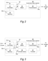
- a second embodiment of the automatic door operator 30 is shown in Fig. 3 .
- the second embodiment is intended for fire door applications.
- the second embodiment of the automatic door operator 30 comprises a controller 31, memory 32, revolution counter 33, motor 34 and transmission 35.
- the second embodiment of the automatic door operator 30 comprises a forced close arrangement 36 adapted to provide mechanical energy via a transfer mechanism 37 to the linkage 20, so as to cause forced closing of the door leaf 14 with respect to the door frame 12 in the event of a fire alarm.
- the forced close arrangement 36 comprises a helical compression spring.
- the compression spring is tensioned by the rotation of the output shaft 35a.
- the transfer mechanism 37 which in the disclosed embodiment includes a pressure roller that acts on a cam curve being connected to the output shaft 35a.
- the forced close arrangement 36 may comprise a different kind of spring, and the transfer mechanism 37 may comprise a different kind of mechanism.
- the controller 31 may receive an external fire alarm signal via a control input 31d and generate a control signal 36a to the forced close arrangement 36, so as to cause release of the accumulated spring force.
- the controller 31 in the automatic door operator 30 is configured to detect intentional manual movements of the door leaf 14 in certain given situations, and to use such detected movements as commands for controlling one or more of the functions 60 of the automatic door operator 30. Corresponding methods are described in Figs. 6 and 7 .
- the automatic door operator 30 has various different functions 60, performable by the controller 31.
- the functions include a first group of functions 61-1, 61-2, ..., 61-n which can be seen as ordinary functions of a typical automatic door operator, relating to various aspects of automatic door opening and closing as well as possible other automatic functions related to, for instance fire alarms.
- the first group of functions 61-1, 61-2, ..., 61-n may consist of functions which are known per se from typical automatic door openers available on the market.
- a second group of functions 61-A, 61-B, ... is provided (the group may consist of an arbitrary number of functions including a single function).
- the functions 61-A, 61-B, ... comprise respective commands 62-A, 62-B,... for initiating, modifying or aborting respective functions 61-n, 61-1 of the first group of functions 61-1, 61-2, ..., 61-n of the automatic door operator performable by the controller 31. Examples will be given later with reference to Figs 4 and 5 .
- Fig. 6 illustrates a method for providing user interaction with the automatic door operator 30 according to a first embodiment.
- the method involves detection of an intentional manual movement of the door leaf 14 by human intervention and includes the following steps.
- the controller 31 is configured to detect a movement of the door leaf 14. The movement is not caused by the motor 34 but rather by human intervention to cause intentional manual movement of the door leaf 14. Since the controller 31 is in control of the actuation of the motor 34, the controller 31 may easily recognize when a movement is not caused by the motor 34.
- the controller 31 is configured to use one or more readings of the revolution counter 33 for determining a current angular position of the door leaf 14.
- the controller 31 is configured to use the determined current angular position for detecting the movement of the door leaf 14. For embodiments like in Fig. 1 , where the swing door assembly 10 comprises a single door leaf 14, the movement will of course be detected for this single door leaf. In other embodiments where the swing door assembly 10 comprises a pair of door leaves, the movement may be detected for one of the door leaves in the pair.
- the controller 31 is configured to identify a predefined movement which matches the detected movement.
- the memory 32 may be adapted to store a definition 32a of such a predefined movement.
- the definition may comprise data representing a defined door leaf angle (such as any of angles ⁇ or ⁇ seen in Figs 4 or 5 ).
- the defined door leaf angle may be expressed as an absolute angle between the door leaf 14 and the door frame 12, or as a relative angle between the door leaf 14 and a reference door leaf angle representing either an open position (such as position ⁇ in Figs 4 and 5 ) or a closed position (such as position ⁇ in Figs 4 and 5 ) of the door leaf 14 with respect to the door frame 12.
- the controller 31 is configured to determine, among the different functions 60 of the automatic door operator 30, a function 61-A or 61-B being associated with the predefined movement.
- the memory 32 may advantageously be adapted to store definitions of a plurality of predefined movements and respective functions 61-A, 61-B being associated therewith.
- the controller 31 may be configured to compare the detected movement to the definitions of the plurality of predefined movements, and identify the predefined movement as the one among the plurality of predefined movements the definition of which matches the detected movement.
- the controller 31 is configured to cause performance of the determined function 61-A or 61-B.
- the determined function 61-A, 61-B comprises a command 62-A, 62-B for initiating, modifying or aborting another one 61-n, 61-1 of the different functions 60 of the automatic door operator performable by the controller 31.
- the determined function 61-A or 61-B is determined among the second group of functions as explained above with reference to Fig. 8 .
- Fig. 7 illustrates a method for providing user interaction with the automatic door operator 30 according to a second embodiment.
- the method of Fig. 7 involves detection of an intentional manual movement of the door leaf 14 by human intervention.
- the method of Fig. 7 includes steps 52, 54, 56 and 58 which are identical or at least essentially identical to the steps 42, 44, 46 and 48 of the method of Fig. 6 .
- the controller 31 is configured to determine a time duration t dur during which the current angular position of the door leaf 14 has satisfied the defined door leaf angle (such as any of angles ⁇ or ⁇ seen in Figs 4 or 5 ) in the definition of the predefined movement, and to cause the performance of the determined function only if the determined time duration t dur exceeds a threshold time t min .
- This functionality is seen in step 57 of Fig. 7 and has an advantage in that it eliminates or at least reduces the risk for spurious - as contrasted to intended - intervention with the door leaf 14.
- t min may be set to an appropriate value, such as for instance n seconds, where 1.0 ⁇ n ⁇ 5.0. In the embodiments described below for Figs. 4 and 5 , t min may be set to, for instance, about 2 seconds. The value of t min may be configurable in some embodiments.
- one of the functions in the first group of functions 61-1, 61-2, ..., 61-n in Fig. 8 is a hold open function.
- the hold open might potentially be very inconvenient when, for instance, the automatic door opener is used in a restroom or hotel room.
- the inconvenience is since the door is kept open for seconds after the user has passed, the integrity of the user may be compromised by the external visibility into the room through an open door, or the opportunity for a trespasser to sneak into the room through the still open door.
- the present invention a physical push or pull of the door towards the closed position by a number of degrees will in effect cancel this time delay.
- the present inventors have realized that the natural response for a person who is intimidated by an undesired hold open period will be to try and close the door by physically pulling or pushing it towards the closed position.
- the use case is believed to be advantageous also in the sense that the user will quite possibly need no prior knowledge on how to operate the door in order to abort the hold open period.
- the use case above is seen at a schematic level in Fig. 4 , where the user makes an intentional manual movement 19a of the door leaf 14 to cause abortion of the automatic hold open function if the movement of the door leaf 14 occurs during the automatic hold open period.
- the intentional movement 19a of the door leaf 14 is at least ⁇ ' degrees from the open position ⁇ towards the closed position ⁇ of the door leaf 14.
- the defined door leaf angle ⁇ in the definition of the predefined movement is ⁇ ' degrees less than the reference door leaf angle of the door leaf 14 in the open position ⁇ .
- the value ⁇ ' of the defined door leaf angle ⁇ may be a preset suitable value, such as for instance any value between 5 and 20 degrees, and may optionally be configurable. Other values less than 5 degrees or more than 20 degrees are however also possible; for instance values less than 5 degrees may be appropriate in some applications.
- the controller 31 detects the intentional movement 19a, finds that it matches the predefined movement, determines that the predefined movement is associated with a function (among functions 61-A and 61-B in Fig. 8 ), and causes the determined function to be performed by executing the command (62-A or 62-B) comprised therein.
- the command causes abortion of the automatic hold open function (among functions 61-1, 61-2, ..., 61-n in Fig. 8 ), whereupon the door leaf 14 will be immediately closed.
- the different functions 60 of the automatic door operator performable by the controller 31 include an automatic hold open function to keep the door leaf 14 open during an automatic hold open period.
- the determined function in this use case is instead to initiate the automatic hold open function when the door leaf is initially in a closed position. This use case is illustrated in Fig. 5 .
- the defined door leaf angle ⁇ in the definition of the predefined movement is ⁇ ' degrees more than the reference door leaf angle of the door leaf 14 in the open position ⁇ .
- the predefined movement is hence defined as a movement of the door leaf 14 from the closed position ⁇ towards and ⁇ ' degrees past the open position ⁇ .
- the value ⁇ ' of the defined door leaf angle ⁇ may be a preset suitable value, such as for instance any value between 0,1 degrees and 10 degrees, and may optionally be configurable. In some embodiments, the value is preferably between 0,5 degrees and 1 degree. Other values, even larger than 10 degrees, are however also possible.
- the controller 31 detects an intentional movement 19b, finds that it matches the predefined movement, determines that the predefined movement is associated with a function (among functions 61-A and 61-B in Fig. 8 ), and causes the determined function to be performed by executing the command (62-A or 62-B) comprised therein.
- the command causes initiation of the automatic hold open function (among functions 61-1, 61-2, ..., 61-n in Fig. 8 ), whereupon the door leaf 14 will be held open.
- the hold open period may be the same as for a normal (automatic) hold open (for instance 5 s), or it may be a different period of time, such as for instance 2 s.
- This use case is particularly suitable for the fire door embodiment of Fig. 3 .
- the different functions 60 of the automatic door operator performable by the controller 31 include generation of a fire alarm, and the determined function is to initiate the generation of the fire alarm.
- the user may make an intentional manual movement 19a of the door leaf 14 to cause generation of a fire alarm when the door leaf 14 open.
- the intentional movement 19a of the door leaf 14 is at least ⁇ ' degrees from the open position ⁇ towards the closed position ⁇ of the door leaf 14.
- the defined door leaf angle ⁇ in the definition of the predefined movement is ⁇ " degrees less than the reference door leaf angle of the door leaf 14 in the open position ⁇ .
- the value ⁇ " of the defined door leaf angle ⁇ may be a preset suitable value, such as for instance any value between 5 and 20 degrees, and may optionally be configurable. Other values less than 5 degrees or more than 20 degrees are however also possible; for instance values less than 5 degrees may be appropriate in some applications.
- the controller 31 detects the intentional movement 19a, finds that it matches the predefined movement, determines that the predefined movement is associated with a function (among functions 61-A and 61-B in Fig. 8 ), and causes the determined function to be performed by executing the command (62-A or 62-B) comprised therein.
- the command causes generation of the fire alarm by invoking a fire alarm function (among functions 61-1, 61-2, ..., 61-n in Fig. 8 ), whereupon the fire alarm may be generated. This may involve sending a control signal to an external system using an output 31e seen in Fig. 3 . This may also involve sending a control signal 36a ( Fig. 2 ) to the forced close arrangement 36.
- the different functions 60 of the automatic door operator 30 performable by the controller 31 include generation of a fire alarm.
- the determined function is instead to reset the automatic door operator 30 after a fire alarm has been generated.
- the defined door leaf angle ⁇ in the definition of the predefined movement is ⁇ " degrees more than the reference door leaf angle of the door leaf 14 in the open position ⁇ .
- the predefined movement is hence defined as a movement of the door leaf 14 from the closed position ⁇ towards and ⁇ " degrees past the open position ⁇ .
- the value ⁇ " of the defined door leaf angle ⁇ may be a preset suitable value, such as for instance any value between 0,1 degrees and 10 degrees, and may optionally be configurable. In some embodiments, the value is preferably between 0,5 degrees and 1 degree. Other values, even larger than 10 degrees, are however also possible.
- the controller 31 detects an intentional movement 19b, finds that it matches the predefined movement, determines that the predefined movement is associated with a function (among functions 61-A and 61-B in Fig. 8 ), and causes the determined function to be performed by executing the command (62-A or 62-B) comprised therein.
- the command causes reset of the automatic door operator 30 after a fire alarm has been generated.
- an automatic hold open function may then be invoked in some embodiments.
Landscapes
- Business, Economics & Management (AREA)
- Emergency Management (AREA)
- Health & Medical Sciences (AREA)
- Public Health (AREA)
- Power-Operated Mechanisms For Wings (AREA)
- Special Wing (AREA)
Claims (21)
- Automatischer Türbetätiger (30) für eine Schwenktüranordnung (10) mit einem Türflügel (14), der drehbar von einem Türrahmen (12) getragen wird, und einem Verbindungsmechanismus (20), der den automatischen Türbetätiger mit dem Türflügel (14) verbindet,wobei der automatische Türbetätiger aufweist:einen Motor (34) zum Bewirken eines Öffnens des Türflügels (14) in Bezug auf den Türrahmen (12); undeine Steuerung (31), die zur Ausführung verschiedener Funktionen (60) des automatischen Türbetätigers eingerichtet ist, wobei die verschiedenen Funktionen (60) eine erste Gruppe von Funktionen (61-1...61-n), die sich auf verschiedene Aspekte eines automatischen Türöffnens und -schließens beziehen, und eine zweite Funktion oder Gruppe von Funktionen (61-A, 61-B) aufweisen, die entsprechende Befehle (62-A, 62-B,...) zum Einleiten, Ändern oder Abbrechen entsprechender Funktionen der ersten Gruppe von Funktionen (61-1...61-n) aufweist,wobei die Steuerung (31) dazu eingerichtet ist:eine Bewegung des Türflügels (14) zu detektieren, die nicht durch den Motor (34) verursacht ist;eine vordefinierte Bewegung zu identifizieren, die zu der detektierten Bewegung passt;unter den verschiedenen Funktionen eine Funktion (61-A, 61-B) zu ermitteln, die mit der vordefinierten Bewegung verknüpft ist; undeine Ausführung der ermittelten Funktion zu verursachen,dadurch gekennzeichnet, dass der automatische Türbetätiger (30) eine Zwangsschließanordnung (36) aufweist, die dazu ausgestaltet ist, mechanische Energie über einen Übertragungsmechanismus (37) an den Verbindungsmechanismus (20) zu liefern, um im Falle eines Feueralarms ein Zwangsschließen des Türflügels in Bezug auf den Türrahmen (12) zu bewirken, undwobei die ermittelte Funktion darin besteht, den automatischen Türbetätiger (30) zurückzusetzen nachdem der Feueralarm erzeugt worden ist.
- Automatischer Türbetätiger (30) nach Anspruch 1, wobei die vordefinierte Bewegung eine absichtliche manuelle Bewegung (19a; 19b) des Türflügels (14) durch menschlichen Eingriff darstellt.
- Automatischer Türbetätiger (30) nach Anspruch 1 oder 2, ferner aufweisend einen Speicher (32), wobei der Speicher eine Definition (32a) der vordefinierten Bewegung speichert, wobei die Definition Daten aufweist, die einen definierten Türflügelwinkel (α, β) darstellen, der als ein absoluter Winkel zwischen dem Türflügel (14) und dem Türrahmen (12) oder als ein relativer Winkel zwischen dem Türflügel (14) und einem Referenz-Türflügelwinkel, der entweder eine offene Position (γ) oder eine geschlossene Position (δ) des Türflügels (14) in Bezug auf den Türrahmen (12) darstellt, ausgedrückt ist.
- Automatischer Türbetätiger (30) nach Anspruch 3, wobei der Speicher (32) Definitionen einer Vielzahl von vordefinierten Bewegungen und entsprechende Funktionen (61-A, 61-B), die mit diesen verknüpft sind, speichert, und wobei die Steuerung (31) dazu eingerichtet ist, die detektierte Bewegung mit den Definitionen der Vielzahl von vordefinierten Bewegungen zu vergleichen und die vordefinierte Bewegung als diejenige unter der Vielzahl von vordefinierten Bewegungen zu identifizieren, deren Definition zu der detektierten Bewegung passt.
- Automatischer Türbetätiger (30) nach Anspruch 3 oder 4, wobei die Steuerung (31) dazu eingerichtet ist, eine aktuelle Winkelposition des Türflügels (14) zu ermitteln und die ermittelte aktuelle Winkelposition zum Detektieren der Bewegung des Türflügels (14) zu verwenden.
- Automatischer Türbetätiger (30) nach Anspruch 5, ferner aufweisend einen Umdrehungszähler (33) für den Motor (34), wobei der Umdrehungszähler mit einem Eingang (31b) der Steuerung (31) verbunden ist, wobei die Steuerung dazu eingerichtet ist, einen oder mehrere Messwerte des Umdrehungszählers (33) zum Ermitteln der aktuellen Winkelposition des Türflügels (14) zu verwenden.
- Automatischer Türbetätiger (30) nach Anspruch 5 oder 6, wobei die Steuerung (31) dazu eingerichtet ist, eine Zeitdauer (tdur) zu ermitteln, während der die aktuelle Winkelposition des Türflügels (14) den definierten Türflügelwinkel (α, β) in der Definition der vordefinierten Bewegung erfüllt hat, und die Ausführung der ermittelten Funktion nur dann zu veranlassen, wenn die ermittelte Zeitdauer (tdur ) eine Schwellenzeit (tmin) überschreitet.
- Automatischer Türbetätiger (30) nach einem der vorhergehenden Ansprüche, wobei die ermittelte Funktion (61-A, 61-B) einen Befehl (62-A, 62-B) zum Einleiten, Ändern oder Abbrechen einer anderen (61-n, 61-1) der verschiedenen Funktionen (60) des automatischen Türbetätigers aufweist, die von der Steuerung (31) ausgeführt werden können.
- Automatischer Türbetätiger (30) nach einem der vorhergehenden Ansprüche, wobei die Steuerung (31) dazu eingerichtet ist, ein externes Feueralarmsignal zu empfangen.
- Automatischer Türbetätiger (30) nach einem der Ansprüche 1-8, wobei die verschiedenen Funktionen (60) des automatischen Türbetätigers, die von der Steuerung (31) ausgeführt werden können, eine Erzeugung eines Feueralarms umfassen.
- Automatischer Türbetätiger (30) nach einem der vorhergehenden Ansprüche, wobei die Schwenktüranordnung (10) einen einzelnen Türflügel (14) aufweist und wobei die Bewegung für diesen einzelnen Türflügel detektiert wird.
- Automatischer Türbetätiger (30) nach einem der Ansprüche 1 bis 10, wobei die Schwenktüranordnung (10) ein Paar Türflügel aufweist und wobei die Bewegung für einen der Türflügel in dem Paar detektiert wird.
- Automatischer Türbetätiger (30) für eine Schwenktüranordnung (10) mit einem Türflügel (14), der drehbar von einem Türrahmen (12) getragen wird, und einem Verbindungsmechanismus (20), der den automatischen Türbetätiger mit dem Türflügel (14) verbindet,wobei der automatische Türbetätiger aufweist:einen Motor (34) zum Bewirken eines Öffnens des Türflügels (14) in Bezug auf den Türrahmen (12); undeine Steuerung (31), die zur Ausführung verschiedener Funktionen (60) des automatischen Türbetätigers eingerichtet ist, wobei die verschiedenen Funktionen (60) eine erste Gruppe von Funktionen (61-1...61-n), die sich auf verschiedene Aspekte eines automatischen Türöffnens und -schließens beziehen, und eine zweite Funktion oder Gruppe von Funktionen (61-A, 61-B) aufweisen, die entsprechende Befehle (62-A, 62-B,...) zum Einleiten, Ändern oder Abbrechen entsprechender Funktionen der ersten Gruppe von Funktionen (61-1...61-n) aufweist,wobei die Steuerung (31) dazu eingerichtet ist:eine Bewegung des Türflügels (14) zu detektieren, die nicht durch den Motor (34) verursacht ist;eine vordefinierte Bewegung zu identifizieren, die zu der detektierten Bewegung passt;unter den verschiedenen Funktionen eine Funktion (61-A, 61-B) zu ermitteln, die mit der vordefinierten Bewegung verknüpft ist; undeine Ausführung der ermittelten Funktion zu verursachen,dadurch gekennzeichnet, dass der automatische Türbetätiger (30) eine Zwangsschließanordnung (36) aufweist, die dazu ausgestaltet ist, mechanische Energie über einen Übertragungsmechanismus (37) an den Verbindungsmechanismus (20) zu liefern, um im Falle des Feueralarms ein Zwangsschließen des Türflügels in Bezug auf den Türrahmen (12) zu bewirken, undwobei die verschiedenen Funktionen (60) des automatischen Türbetätigers, die von der Steuerung (31) ausgeführt werden können, eine Erzeugung eines Feueralarms umfassen, und wobei die ermittelte Funktion darin besteht, die Erzeugung des Feueralarms auszulösen, um im Falle des Feueralarms ein Zwangsschließen des Türflügels 14 in Bezug auf den Türrahmen 12 zu bewirken.
- Automatischer Türbetätiger (30) nach Anspruch 13, wobei die vordefinierte Bewegung eine absichtliche manuelle Bewegung (19a; 19b) des Türflügels (14) durch menschlichen Eingriff darstellt.
- Automatischer Türbetätiger (30) nach Anspruch 13 oder 14, ferner aufweisend einen Speicher (32), wobei der Speicher dazu ausgelegt ist, eine Definition (32a) der vordefinierten Bewegung zu speichern, wobei die Definition Daten aufweist, die einen definierten Türflügelwinkel (α, β) darstellen, der als ein absoluter Winkel zwischen dem Türflügel (14) und dem Türrahmen (12) oder als ein relativer Winkel zwischen dem Türflügel (14) und einem Referenz-Türflügelwinkel, der entweder eine offene Position (γ) oder eine geschlossene Position (δ) des Türflügels (14) in Bezug auf den Türrahmen (12) darstellt, ausgedrückt ist.
- Türbetätigungsssystem (1), aufweisend:einen automatischen Türbetätiger (30) nach einem der Ansprüche 1-15;einen Türrahmen (12); undeine Schwenktüranordnung (10) mit einem Türflügel (14), der drehbar von dem Türrahmen (12) getragen wird.
- Verfahren (40; 50) zum Bereitstellen einer Benutzerinteraktion mit einem automatischen Türbetätiger (30) nach einem der Ansprüche 1 bis 15 in einem Türbetätigungsssystem, das ferner einen Türrahmen (12), eine Schwenktüranordnung (10) mit einem Türflügel (14), der drehbar von einem Türrahmen (12) getragen wird, einen Verbindungsmechanismus (20), der den automatischen Türbetätiger mit dem Türflügel (14) verbindet, und eine Zwangsschließanordnung (36), die dazu ausgestaltet ist, mechanische Energie über einen Übertragungsmechanismus (37) an den Verbindungsmechanismus (20) zu liefern, um im Falle eines Feueralarms ein Zwangsschließen des Türflügels (14) in Bezug auf den Türrahmen (12) zu bewirken, wobei das Verfahren umfasst:Detektieren (42; 52) einer Bewegung des Türflügels (14), die nicht durch einen Motor (34) des automatischen Türbetätigers (30) verursacht ist;Identifizieren (44; 54) einer vordefinierten Bewegung, die zu der detektierten Bewegung passt;Ermitteln (46; 56), unter verschiedenen Funktionen (60) des automatischen Türbetätigers, einer Funktion (61-A, 61-B), die mit der vordefinierten Bewegung verknüpft ist;Verursachen (48; 58) einer Ausführung der ermittelten Funktion; undZwangsschließen des Türflügels (14) in Bezug auf den Türrahmen (12) im Falle eines Feueralarms,wobei die ermittelte Funktion darin besteht, ein Steuersignal (36a) an die Zwangsschließanordnung (36) zu senden.
- Verfahren (50) nach Anspruch 17, ferner aufweisend:Ermitteln (57) einer Zeitdauer (tdur), während der die aktuelle Winkelposition des Türflügels (14) den definierten Türflügelwinkel (α, β) in der Definition der vordefinierten Bewegung erfüllt hat; undVeranlassen (58) der Ausführung der ermittelten Funktion (61-A, 61-B) nur dann, wenn die ermittelte Zeitdauer (tdur) eine Schwellenzeit (tmin) überschreitet.
- Verfahren nach Anspruch 17 oder 18, ferner aufweisend:Empfang eines externen Feueralarmsignals; undErzeugung des Steuersignals (36a),wobei das an die Zwangsschließanordnung (36) gesendete Steuersignal (36a) eine Rückstellung des automatischen Türbetätigers (30) bewirkt.
- Verfahren nach Anspruch 19, ferner aufweisend:
Aktivieren einer automatischen Offenhaltefunktion nach der Rückstellung des automatischen Türbetätigers (30). - Verfahren nach Anspruch 17 oder 18, wobei:
die ermittelte Funktion ferner Auslösen der Erzeugung des Feueralarms beinhaltet, wobei das Verfahren ferner aufweist:
Senden des Steuersignals (36a) an die Zwangsschließanordnung (36) bei Erzeugung des Feueralarms, wodurch das Zwangsschließen des Türflügels (14) in Bezug auf den Türrahmen (12) bewirkt wird.
Applications Claiming Priority (2)
| Application Number | Priority Date | Filing Date | Title |
|---|---|---|---|
| SE1630292 | 2016-12-07 | ||
| PCT/EP2017/081436 WO2018104258A1 (en) | 2016-12-07 | 2017-12-05 | Automatic door operator for a swing door assembly |
Publications (2)
| Publication Number | Publication Date |
|---|---|
| EP3551823A1 EP3551823A1 (de) | 2019-10-16 |
| EP3551823B1 true EP3551823B1 (de) | 2023-06-07 |
Family
ID=60569929
Family Applications (1)
| Application Number | Title | Priority Date | Filing Date |
|---|---|---|---|
| EP17808483.6A Active EP3551823B1 (de) | 2016-12-07 | 2017-12-05 | Automatischer türbetätiger für eine schwenktüranordnung |
Country Status (7)
| Country | Link |
|---|---|
| US (1) | US11072965B2 (de) |
| EP (1) | EP3551823B1 (de) |
| AU (1) | AU2017371116B2 (de) |
| CA (1) | CA3041080A1 (de) |
| DK (1) | DK3551823T3 (de) |
| RU (1) | RU2754751C2 (de) |
| WO (1) | WO2018104258A1 (de) |
Families Citing this family (13)
| Publication number | Priority date | Publication date | Assignee | Title |
|---|---|---|---|---|
| EP3615753B1 (de) * | 2017-04-24 | 2025-11-19 | Assa Abloy Entrance Systems AB | Schwingtürbetätigungsanordnung |
| JP6870542B2 (ja) * | 2017-08-31 | 2021-05-12 | 株式会社ダイフク | 物品搬送設備 |
| US11536075B2 (en) * | 2018-08-09 | 2022-12-27 | Assa Abloy Entrance Systems Ab | Door operator and method of its operation |
| US11549302B2 (en) | 2019-03-14 | 2023-01-10 | ASSA ABLOY Accessories and Door Controls Group, Inc. | Door system with improved installation, set-up, and cloning |
| AU2020273712A1 (en) * | 2019-05-13 | 2021-10-07 | Assa Abloy Entrance Systems Ab | A swing door operator for moving a swing door leaf in a swing path between an open and closed position, a swing door and a room with a swing door |
| CN113994062B (zh) * | 2019-06-13 | 2023-10-27 | 亚萨合莱自动门系统有限公司 | 在动力模式和无动力模式中可操作的摆动门操作器 |
| WO2020249455A1 (en) * | 2019-06-13 | 2020-12-17 | Assa Abloy Entrance Systems Ab | Method for testing a door operator |
| AU2020295632B2 (en) * | 2019-06-17 | 2025-10-16 | Assa Abloy Entrance Systems Ab | Swing door-based entrance system with improved operability in emergency mode |
| US11532192B2 (en) * | 2019-08-30 | 2022-12-20 | ASSA ABLOY Accessories and Door Controls Group, Inc. | Door system with authentication and activation |
| CA3152073A1 (en) | 2019-09-23 | 2021-04-01 | Brian D. Hass | Door system with active monitoring |
| JP7288574B2 (ja) * | 2020-03-17 | 2023-06-08 | 株式会社エー・アンド・デイ | 天びん用風防 |
| KR102521286B1 (ko) * | 2020-09-08 | 2023-04-13 | 엘지전자 주식회사 | 투명 디스플레이를 이용하여 자동문을 구현하는 시스템 |
| EP4563780A1 (de) * | 2023-11-30 | 2025-06-04 | dormakaba Deutschland GmbH | Anordnung für eine tür und verfahren zum betrieb der anordnung |
Citations (5)
| Publication number | Priority date | Publication date | Assignee | Title |
|---|---|---|---|---|
| US4952080A (en) | 1989-05-12 | 1990-08-28 | The Stanley Works | Automatic assist for swing-door operator |
| US20090249699A1 (en) | 2008-04-02 | 2009-10-08 | Leon Yulkowski | Concealed electrical door operator |
| DE102009004503A1 (de) | 2009-01-09 | 2010-07-15 | Dorma Gmbh + Co. Kg | Verfahren zum Betrieb eines Drehflügelbetätigers und damit betriebene Drehflügelbetätiger |
| DE102015200289A1 (de) | 2015-01-13 | 2016-07-14 | Geze Gmbh | Elektromechanischer Antrieb zum Betätigen eines beweglichen Flügels und korrespondierende Tür |
| DE102015104825A1 (de) | 2015-01-16 | 2016-07-21 | Hörmann KG Antriebstechnik | Verfahren zum Betreiben eines Türantriebs, Türantriebssteuerung, Türantrieb und Drehflügeltür |
Family Cites Families (28)
| Publication number | Priority date | Publication date | Assignee | Title |
|---|---|---|---|---|
| BE792144A (fr) * | 1972-01-07 | 1973-03-16 | Rixson Firemark | Ferme-porte repondant a certaines conditions |
| US3908309A (en) * | 1972-01-07 | 1975-09-30 | Rixson Firemark | Particulate products of combustion detector for closure frame |
| US3905063A (en) * | 1972-01-07 | 1975-09-16 | Rixson Firemark | Condition responsive door holder-closer |
| US3926461A (en) * | 1974-08-01 | 1975-12-16 | Rixson Firemark | Electrically actuated door holder and release |
| US3934306A (en) * | 1975-01-06 | 1976-01-27 | Federal Sign And Signal Corporation | Door closure device |
| JPS58178777A (ja) * | 1982-04-12 | 1983-10-19 | 千蔵工業株式会社 | スイングドアの自動開閉装置 |
| DE3612918A1 (de) | 1986-04-17 | 1987-10-22 | Dorma Gmbh & Co Kg | Schliessfolgeregelvorrichtung fuer eine zweifluegelige tuer |
| US5018304A (en) * | 1990-05-10 | 1991-05-28 | F. L. Saino Manufacturing Co. | Door operator |
| US5878530A (en) * | 1994-10-18 | 1999-03-09 | Eccleston Mechanical | Remotely controllable automatic door operator permitting active and passive door operation |
| DE19652600C5 (de) * | 1996-12-18 | 2010-10-28 | Dorma Gmbh + Co. Kg | Notöffnungsvorrichtung für eine Drehfalttür oder ein Drehfalttor |
| FI109227B (fi) * | 2000-03-15 | 2002-06-14 | Goeran Sundholm | Palo-ovi ja palonsuojausjärjestelmä |
| US6634140B1 (en) * | 2000-09-13 | 2003-10-21 | Power Access Corporation | Automatic door opener |
| US6751909B2 (en) | 2001-02-06 | 2004-06-22 | The Stanley Works | Automatic door control system |
| US8225458B1 (en) | 2001-07-13 | 2012-07-24 | Hoffberg Steven M | Intelligent door restraint |
| US7138912B2 (en) * | 2003-03-20 | 2006-11-21 | The Chamberlain Group, Inc. | Movable barrier operations method and apparatus |
| US6891479B1 (en) | 2003-06-12 | 2005-05-10 | Jon E. Eccleston | Remotely controllable automatic door operator and closer |
| WO2005021914A1 (en) * | 2003-09-03 | 2005-03-10 | Dpnkd Holdings Inc. | Automatic portable door operating system |
| US8169169B2 (en) | 2005-04-13 | 2012-05-01 | Brian Hass | Door operator for controlling a door and method of same |
| US7449856B2 (en) | 2005-11-14 | 2008-11-11 | Motion Access, L.L.C. | Universal controller for automatic door systems |
| US20070277440A1 (en) * | 2006-05-31 | 2007-12-06 | Paul Luetkenhaus | Door opener |
| US8405337B2 (en) | 2008-11-12 | 2013-03-26 | Globe Motors, Inc. | Method of controlling an automatic door system |
| GB0907954D0 (en) * | 2009-05-08 | 2009-06-24 | Fireco Ltd | Appararatus for controlling the movement of a closure |
| KR20110001581A (ko) | 2009-06-30 | 2011-01-06 | 주식회사 하이닉스반도체 | 불휘발성 메모리 장치의 카피백 동작 방법 |
| US8527101B2 (en) * | 2010-04-16 | 2013-09-03 | Yale Security Inc. | Door closer assembly |
| US8773237B2 (en) * | 2010-04-16 | 2014-07-08 | Yale Security Inc. | Door closer with teach mode |
| CN103237948B (zh) * | 2010-12-03 | 2015-05-27 | 纳博特斯克有限公司 | 自动门用传感器 |
| EP4350648A3 (de) * | 2016-05-16 | 2024-06-19 | Schlage Lock Company LLC | Kommunikation eines türschliessers |
| US11549302B2 (en) * | 2019-03-14 | 2023-01-10 | ASSA ABLOY Accessories and Door Controls Group, Inc. | Door system with improved installation, set-up, and cloning |
-
2017
- 2017-12-05 CA CA3041080A patent/CA3041080A1/en active Pending
- 2017-12-05 DK DK17808483.6T patent/DK3551823T3/da active
- 2017-12-05 EP EP17808483.6A patent/EP3551823B1/de active Active
- 2017-12-05 US US16/347,966 patent/US11072965B2/en active Active
- 2017-12-05 AU AU2017371116A patent/AU2017371116B2/en active Active
- 2017-12-05 RU RU2019119604A patent/RU2754751C2/ru active
- 2017-12-05 WO PCT/EP2017/081436 patent/WO2018104258A1/en not_active Ceased
Patent Citations (5)
| Publication number | Priority date | Publication date | Assignee | Title |
|---|---|---|---|---|
| US4952080A (en) | 1989-05-12 | 1990-08-28 | The Stanley Works | Automatic assist for swing-door operator |
| US20090249699A1 (en) | 2008-04-02 | 2009-10-08 | Leon Yulkowski | Concealed electrical door operator |
| DE102009004503A1 (de) | 2009-01-09 | 2010-07-15 | Dorma Gmbh + Co. Kg | Verfahren zum Betrieb eines Drehflügelbetätigers und damit betriebene Drehflügelbetätiger |
| DE102015200289A1 (de) | 2015-01-13 | 2016-07-14 | Geze Gmbh | Elektromechanischer Antrieb zum Betätigen eines beweglichen Flügels und korrespondierende Tür |
| DE102015104825A1 (de) | 2015-01-16 | 2016-07-21 | Hörmann KG Antriebstechnik | Verfahren zum Betreiben eines Türantriebs, Türantriebssteuerung, Türantrieb und Drehflügeltür |
Non-Patent Citations (3)
| Title |
|---|
| ANONYMOUS: "ED 100 / ED 250 - Swing door operators in modular design", DORMA BROCHURE, 1 April 2011 (2011-04-01), pages 1 - 24, XP093167265 |
| ANONYMOUS: "Schlösser und Baubeschläge - Türschließmittel mit kontrolliertem Schließablauf- Teil 4: Drehflügeltürantriebe mit Selbstschließfunktion", DEUTSCHE NORM DIN 18263-4, 1 April 2015 (2015-04-01), pages 1 - 20, XP093169629 |
| BAU. SHOP GMBH: "Schließfolgeregler", 5 June 2016 (2016-06-05), pages 1 - 2, XP093169631, Retrieved from the Internet <URL:https://www.youtube.com/watch?v=JaUvzMVYjyo> [retrieved on 20240603] |
Also Published As
| Publication number | Publication date |
|---|---|
| AU2017371116A1 (en) | 2019-04-04 |
| RU2019119604A (ru) | 2021-01-11 |
| RU2754751C2 (ru) | 2021-09-07 |
| DK3551823T3 (da) | 2023-06-26 |
| NZ751621A (en) | 2023-12-22 |
| EP3551823A1 (de) | 2019-10-16 |
| WO2018104258A1 (en) | 2018-06-14 |
| US20190292835A1 (en) | 2019-09-26 |
| AU2017371116B2 (en) | 2023-09-21 |
| CA3041080A1 (en) | 2018-06-14 |
| US11072965B2 (en) | 2021-07-27 |
| RU2019119604A3 (de) | 2021-03-18 |
Similar Documents
| Publication | Publication Date | Title |
|---|---|---|
| EP3551823B1 (de) | Automatischer türbetätiger für eine schwenktüranordnung | |
| CN113994063B (zh) | 在紧急模式中具有改进的可操作性的基于摆动门的入口系统 | |
| EP3963166B1 (de) | Schwingtürbasiertes eingangssystem mit automatischer erkennung der verbindungsreduktionskurve | |
| US20220268090A1 (en) | Control arrangement for an entrance system having one or more swing door movable door members | |
| US11536078B2 (en) | Configuration of entrance systems having one or more movable door members | |
| WO2021052827A1 (en) | Testing system for swing door-based entrance system | |
| CN112236575B (zh) | 进入系统 | |
| EP3781772B1 (de) | Fingerquetschschutz für ein eingangssystem | |
| US6611205B2 (en) | Gate operator safety system | |
| US20220282545A1 (en) | Entrance system and method of operating such an entrance system | |
| EP3556982A1 (de) | Eingangssystem | |
| CN208564276U (zh) | 一种防夹安全门 | |
| JP3220036B2 (ja) | 安全装置付きパワーウィンド装置 | |
| KR20070052630A (ko) | 디지털 도어락과 연동제어 기능을 갖는 세대문 자동 개폐장치 | |
| WO2023094343A1 (en) | Revolving door system | |
| JP2002309853A (ja) | 開閉扉 |
Legal Events
| Date | Code | Title | Description |
|---|---|---|---|
| STAA | Information on the status of an ep patent application or granted ep patent |
Free format text: STATUS: UNKNOWN |
|
| STAA | Information on the status of an ep patent application or granted ep patent |
Free format text: STATUS: THE INTERNATIONAL PUBLICATION HAS BEEN MADE |
|
| PUAI | Public reference made under article 153(3) epc to a published international application that has entered the european phase |
Free format text: ORIGINAL CODE: 0009012 |
|
| STAA | Information on the status of an ep patent application or granted ep patent |
Free format text: STATUS: REQUEST FOR EXAMINATION WAS MADE |
|
| 17P | Request for examination filed |
Effective date: 20190620 |
|
| AK | Designated contracting states |
Kind code of ref document: A1 Designated state(s): AL AT BE BG CH CY CZ DE DK EE ES FI FR GB GR HR HU IE IS IT LI LT LU LV MC MK MT NL NO PL PT RO RS SE SI SK SM TR |
|
| AX | Request for extension of the european patent |
Extension state: BA ME |
|
| DAV | Request for validation of the european patent (deleted) | ||
| DAX | Request for extension of the european patent (deleted) | ||
| GRAP | Despatch of communication of intention to grant a patent |
Free format text: ORIGINAL CODE: EPIDOSNIGR1 |
|
| STAA | Information on the status of an ep patent application or granted ep patent |
Free format text: STATUS: GRANT OF PATENT IS INTENDED |
|
| INTG | Intention to grant announced |
Effective date: 20221017 |
|
| GRAS | Grant fee paid |
Free format text: ORIGINAL CODE: EPIDOSNIGR3 |
|
| RIN1 | Information on inventor provided before grant (corrected) |
Inventor name: SOEDERQVIST, SVEN-GUNNAR |
|
| GRAA | (expected) grant |
Free format text: ORIGINAL CODE: 0009210 |
|
| STAA | Information on the status of an ep patent application or granted ep patent |
Free format text: STATUS: THE PATENT HAS BEEN GRANTED |
|
| AK | Designated contracting states |
Kind code of ref document: B1 Designated state(s): AL AT BE BG CH CY CZ DE DK EE ES FI FR GB GR HR HU IE IS IT LI LT LU LV MC MK MT NL NO PL PT RO RS SE SI SK SM TR |
|
| REG | Reference to a national code |
Ref country code: GB Ref legal event code: FG4D |
|
| REG | Reference to a national code |
Ref country code: CH Ref legal event code: EP Ref country code: AT Ref legal event code: REF Ref document number: 1575581 Country of ref document: AT Kind code of ref document: T Effective date: 20230615 Ref country code: DE Ref legal event code: R096 Ref document number: 602017069789 Country of ref document: DE |
|
| REG | Reference to a national code |
Ref country code: DK Ref legal event code: T3 Effective date: 20230621 |
|
| REG | Reference to a national code |
Ref country code: SE Ref legal event code: TRGR |
|
| REG | Reference to a national code |
Ref country code: NL Ref legal event code: FP |
|
| REG | Reference to a national code |
Ref country code: LT Ref legal event code: MG9D |
|
| PG25 | Lapsed in a contracting state [announced via postgrant information from national office to epo] |
Ref country code: NO Free format text: LAPSE BECAUSE OF FAILURE TO SUBMIT A TRANSLATION OF THE DESCRIPTION OR TO PAY THE FEE WITHIN THE PRESCRIBED TIME-LIMIT Effective date: 20230907 Ref country code: ES Free format text: LAPSE BECAUSE OF FAILURE TO SUBMIT A TRANSLATION OF THE DESCRIPTION OR TO PAY THE FEE WITHIN THE PRESCRIBED TIME-LIMIT Effective date: 20230607 |
|
| REG | Reference to a national code |
Ref country code: AT Ref legal event code: MK05 Ref document number: 1575581 Country of ref document: AT Kind code of ref document: T Effective date: 20230607 |
|
| PG25 | Lapsed in a contracting state [announced via postgrant information from national office to epo] |
Ref country code: RS Free format text: LAPSE BECAUSE OF FAILURE TO SUBMIT A TRANSLATION OF THE DESCRIPTION OR TO PAY THE FEE WITHIN THE PRESCRIBED TIME-LIMIT Effective date: 20230607 Ref country code: LV Free format text: LAPSE BECAUSE OF FAILURE TO SUBMIT A TRANSLATION OF THE DESCRIPTION OR TO PAY THE FEE WITHIN THE PRESCRIBED TIME-LIMIT Effective date: 20230607 Ref country code: LT Free format text: LAPSE BECAUSE OF FAILURE TO SUBMIT A TRANSLATION OF THE DESCRIPTION OR TO PAY THE FEE WITHIN THE PRESCRIBED TIME-LIMIT Effective date: 20230607 Ref country code: HR Free format text: LAPSE BECAUSE OF FAILURE TO SUBMIT A TRANSLATION OF THE DESCRIPTION OR TO PAY THE FEE WITHIN THE PRESCRIBED TIME-LIMIT Effective date: 20230607 Ref country code: GR Free format text: LAPSE BECAUSE OF FAILURE TO SUBMIT A TRANSLATION OF THE DESCRIPTION OR TO PAY THE FEE WITHIN THE PRESCRIBED TIME-LIMIT Effective date: 20230908 |
|
| PG25 | Lapsed in a contracting state [announced via postgrant information from national office to epo] |
Ref country code: FI Free format text: LAPSE BECAUSE OF FAILURE TO SUBMIT A TRANSLATION OF THE DESCRIPTION OR TO PAY THE FEE WITHIN THE PRESCRIBED TIME-LIMIT Effective date: 20230607 |
|
| PG25 | Lapsed in a contracting state [announced via postgrant information from national office to epo] |
Ref country code: SK Free format text: LAPSE BECAUSE OF FAILURE TO SUBMIT A TRANSLATION OF THE DESCRIPTION OR TO PAY THE FEE WITHIN THE PRESCRIBED TIME-LIMIT Effective date: 20230607 |
|
| PG25 | Lapsed in a contracting state [announced via postgrant information from national office to epo] |
Ref country code: IS Free format text: LAPSE BECAUSE OF FAILURE TO SUBMIT A TRANSLATION OF THE DESCRIPTION OR TO PAY THE FEE WITHIN THE PRESCRIBED TIME-LIMIT Effective date: 20231007 |
|
| PG25 | Lapsed in a contracting state [announced via postgrant information from national office to epo] |
Ref country code: SM Free format text: LAPSE BECAUSE OF FAILURE TO SUBMIT A TRANSLATION OF THE DESCRIPTION OR TO PAY THE FEE WITHIN THE PRESCRIBED TIME-LIMIT Effective date: 20230607 Ref country code: SK Free format text: LAPSE BECAUSE OF FAILURE TO SUBMIT A TRANSLATION OF THE DESCRIPTION OR TO PAY THE FEE WITHIN THE PRESCRIBED TIME-LIMIT Effective date: 20230607 Ref country code: RO Free format text: LAPSE BECAUSE OF FAILURE TO SUBMIT A TRANSLATION OF THE DESCRIPTION OR TO PAY THE FEE WITHIN THE PRESCRIBED TIME-LIMIT Effective date: 20230607 Ref country code: PT Free format text: LAPSE BECAUSE OF FAILURE TO SUBMIT A TRANSLATION OF THE DESCRIPTION OR TO PAY THE FEE WITHIN THE PRESCRIBED TIME-LIMIT Effective date: 20231009 Ref country code: IS Free format text: LAPSE BECAUSE OF FAILURE TO SUBMIT A TRANSLATION OF THE DESCRIPTION OR TO PAY THE FEE WITHIN THE PRESCRIBED TIME-LIMIT Effective date: 20231007 Ref country code: EE Free format text: LAPSE BECAUSE OF FAILURE TO SUBMIT A TRANSLATION OF THE DESCRIPTION OR TO PAY THE FEE WITHIN THE PRESCRIBED TIME-LIMIT Effective date: 20230607 Ref country code: CZ Free format text: LAPSE BECAUSE OF FAILURE TO SUBMIT A TRANSLATION OF THE DESCRIPTION OR TO PAY THE FEE WITHIN THE PRESCRIBED TIME-LIMIT Effective date: 20230607 Ref country code: AT Free format text: LAPSE BECAUSE OF FAILURE TO SUBMIT A TRANSLATION OF THE DESCRIPTION OR TO PAY THE FEE WITHIN THE PRESCRIBED TIME-LIMIT Effective date: 20230607 |
|
| PG25 | Lapsed in a contracting state [announced via postgrant information from national office to epo] |
Ref country code: PL Free format text: LAPSE BECAUSE OF FAILURE TO SUBMIT A TRANSLATION OF THE DESCRIPTION OR TO PAY THE FEE WITHIN THE PRESCRIBED TIME-LIMIT Effective date: 20230607 |
|
| REG | Reference to a national code |
Ref country code: DE Ref legal event code: R026 Ref document number: 602017069789 Country of ref document: DE |
|
| PLBI | Opposition filed |
Free format text: ORIGINAL CODE: 0009260 |
|
| 26 | Opposition filed |
Opponent name: GEZE GMBH Effective date: 20240305 Opponent name: DORMAKABA DEUTSCHLAND GMBH Effective date: 20240304 |
|
| PG25 | Lapsed in a contracting state [announced via postgrant information from national office to epo] |
Ref country code: SI Free format text: LAPSE BECAUSE OF FAILURE TO SUBMIT A TRANSLATION OF THE DESCRIPTION OR TO PAY THE FEE WITHIN THE PRESCRIBED TIME-LIMIT Effective date: 20230607 |
|
| PLAX | Notice of opposition and request to file observation + time limit sent |
Free format text: ORIGINAL CODE: EPIDOSNOBS2 |
|
| PG25 | Lapsed in a contracting state [announced via postgrant information from national office to epo] |
Ref country code: SI Free format text: LAPSE BECAUSE OF FAILURE TO SUBMIT A TRANSLATION OF THE DESCRIPTION OR TO PAY THE FEE WITHIN THE PRESCRIBED TIME-LIMIT Effective date: 20230607 Ref country code: IT Free format text: LAPSE BECAUSE OF FAILURE TO SUBMIT A TRANSLATION OF THE DESCRIPTION OR TO PAY THE FEE WITHIN THE PRESCRIBED TIME-LIMIT Effective date: 20230607 |
|
| PLAB | Opposition data, opponent's data or that of the opponent's representative modified |
Free format text: ORIGINAL CODE: 0009299OPPO |
|
| R26 | Opposition filed (corrected) |
Opponent name: GEZE GMBH Effective date: 20240305 |
|
| REG | Reference to a national code |
Ref country code: CH Ref legal event code: PL |
|
| PG25 | Lapsed in a contracting state [announced via postgrant information from national office to epo] |
Ref country code: LU Free format text: LAPSE BECAUSE OF NON-PAYMENT OF DUE FEES Effective date: 20231205 |
|
| PG25 | Lapsed in a contracting state [announced via postgrant information from national office to epo] |
Ref country code: MC Free format text: LAPSE BECAUSE OF FAILURE TO SUBMIT A TRANSLATION OF THE DESCRIPTION OR TO PAY THE FEE WITHIN THE PRESCRIBED TIME-LIMIT Effective date: 20230607 |
|
| REG | Reference to a national code |
Ref country code: BE Ref legal event code: MM Effective date: 20231231 |
|
| PG25 | Lapsed in a contracting state [announced via postgrant information from national office to epo] |
Ref country code: MC Free format text: LAPSE BECAUSE OF FAILURE TO SUBMIT A TRANSLATION OF THE DESCRIPTION OR TO PAY THE FEE WITHIN THE PRESCRIBED TIME-LIMIT Effective date: 20230607 Ref country code: LU Free format text: LAPSE BECAUSE OF NON-PAYMENT OF DUE FEES Effective date: 20231205 |
|
| PLBB | Reply of patent proprietor to notice(s) of opposition received |
Free format text: ORIGINAL CODE: EPIDOSNOBS3 |
|
| REG | Reference to a national code |
Ref country code: IE Ref legal event code: MM4A |
|
| PG25 | Lapsed in a contracting state [announced via postgrant information from national office to epo] |
Ref country code: IE Free format text: LAPSE BECAUSE OF NON-PAYMENT OF DUE FEES Effective date: 20231205 |
|
| PG25 | Lapsed in a contracting state [announced via postgrant information from national office to epo] |
Ref country code: BE Free format text: LAPSE BECAUSE OF NON-PAYMENT OF DUE FEES Effective date: 20231231 |
|
| PG25 | Lapsed in a contracting state [announced via postgrant information from national office to epo] |
Ref country code: FR Free format text: LAPSE BECAUSE OF NON-PAYMENT OF DUE FEES Effective date: 20231231 |
|
| PG25 | Lapsed in a contracting state [announced via postgrant information from national office to epo] |
Ref country code: CH Free format text: LAPSE BECAUSE OF NON-PAYMENT OF DUE FEES Effective date: 20231231 |
|
| PG25 | Lapsed in a contracting state [announced via postgrant information from national office to epo] |
Ref country code: IE Free format text: LAPSE BECAUSE OF NON-PAYMENT OF DUE FEES Effective date: 20231205 Ref country code: FR Free format text: LAPSE BECAUSE OF NON-PAYMENT OF DUE FEES Effective date: 20231231 Ref country code: CH Free format text: LAPSE BECAUSE OF NON-PAYMENT OF DUE FEES Effective date: 20231231 Ref country code: BE Free format text: LAPSE BECAUSE OF NON-PAYMENT OF DUE FEES Effective date: 20231231 |
|
| PG25 | Lapsed in a contracting state [announced via postgrant information from national office to epo] |
Ref country code: BG Free format text: LAPSE BECAUSE OF FAILURE TO SUBMIT A TRANSLATION OF THE DESCRIPTION OR TO PAY THE FEE WITHIN THE PRESCRIBED TIME-LIMIT Effective date: 20230607 |
|
| PG25 | Lapsed in a contracting state [announced via postgrant information from national office to epo] |
Ref country code: BG Free format text: LAPSE BECAUSE OF FAILURE TO SUBMIT A TRANSLATION OF THE DESCRIPTION OR TO PAY THE FEE WITHIN THE PRESCRIBED TIME-LIMIT Effective date: 20230607 |
|
| PG25 | Lapsed in a contracting state [announced via postgrant information from national office to epo] |
Ref country code: CY Free format text: LAPSE BECAUSE OF FAILURE TO SUBMIT A TRANSLATION OF THE DESCRIPTION OR TO PAY THE FEE WITHIN THE PRESCRIBED TIME-LIMIT; INVALID AB INITIO Effective date: 20171205 |
|
| PG25 | Lapsed in a contracting state [announced via postgrant information from national office to epo] |
Ref country code: HU Free format text: LAPSE BECAUSE OF FAILURE TO SUBMIT A TRANSLATION OF THE DESCRIPTION OR TO PAY THE FEE WITHIN THE PRESCRIBED TIME-LIMIT; INVALID AB INITIO Effective date: 20171205 |
|
| PG25 | Lapsed in a contracting state [announced via postgrant information from national office to epo] |
Ref country code: TR Free format text: LAPSE BECAUSE OF FAILURE TO SUBMIT A TRANSLATION OF THE DESCRIPTION OR TO PAY THE FEE WITHIN THE PRESCRIBED TIME-LIMIT Effective date: 20230607 |
|
| PGFP | Annual fee paid to national office [announced via postgrant information from national office to epo] |
Ref country code: NL Payment date: 20251112 Year of fee payment: 9 |
|
| PGFP | Annual fee paid to national office [announced via postgrant information from national office to epo] |
Ref country code: DE Payment date: 20251111 Year of fee payment: 9 |
|
| PGFP | Annual fee paid to national office [announced via postgrant information from national office to epo] |
Ref country code: GB Payment date: 20251113 Year of fee payment: 9 |
|
| PGFP | Annual fee paid to national office [announced via postgrant information from national office to epo] |
Ref country code: DK Payment date: 20251212 Year of fee payment: 9 |
|
| PGFP | Annual fee paid to national office [announced via postgrant information from national office to epo] |
Ref country code: SE Payment date: 20251112 Year of fee payment: 9 |