EP3551786B1 - Elektropolierverfahren und elektrolyt hierzu - Google Patents
Elektropolierverfahren und elektrolyt hierzu Download PDFInfo
- Publication number
- EP3551786B1 EP3551786B1 EP17816393.7A EP17816393A EP3551786B1 EP 3551786 B1 EP3551786 B1 EP 3551786B1 EP 17816393 A EP17816393 A EP 17816393A EP 3551786 B1 EP3551786 B1 EP 3551786B1
- Authority
- EP
- European Patent Office
- Prior art keywords
- pulse
- electrolyte
- current
- component
- weight
- Prior art date
- Legal status (The legal status is an assumption and is not a legal conclusion. Google has not performed a legal analysis and makes no representation as to the accuracy of the status listed.)
- Active
Links
Images

Classifications
-
- C—CHEMISTRY; METALLURGY
- C25—ELECTROLYTIC OR ELECTROPHORETIC PROCESSES; APPARATUS THEREFOR
- C25F—PROCESSES FOR THE ELECTROLYTIC REMOVAL OF MATERIALS FROM OBJECTS; APPARATUS THEREFOR
- C25F3/00—Electrolytic etching or polishing
- C25F3/16—Polishing
-
- B—PERFORMING OPERATIONS; TRANSPORTING
- B22—CASTING; POWDER METALLURGY
- B22F—WORKING METALLIC POWDER; MANUFACTURE OF ARTICLES FROM METALLIC POWDER; MAKING METALLIC POWDER; APPARATUS OR DEVICES SPECIALLY ADAPTED FOR METALLIC POWDER
- B22F10/00—Additive manufacturing of workpieces or articles from metallic powder
- B22F10/60—Treatment of workpieces or articles after build-up
- B22F10/62—Treatment of workpieces or articles after build-up by chemical means
-
- B—PERFORMING OPERATIONS; TRANSPORTING
- B22—CASTING; POWDER METALLURGY
- B22F—WORKING METALLIC POWDER; MANUFACTURE OF ARTICLES FROM METALLIC POWDER; MAKING METALLIC POWDER; APPARATUS OR DEVICES SPECIALLY ADAPTED FOR METALLIC POWDER
- B22F3/00—Manufacture of workpieces or articles from metallic powder characterised by the manner of compacting or sintering; Apparatus specially adapted therefor ; Presses and furnaces
- B22F3/24—After-treatment of workpieces or articles
-
- B—PERFORMING OPERATIONS; TRANSPORTING
- B33—ADDITIVE MANUFACTURING TECHNOLOGY
- B33Y—ADDITIVE MANUFACTURING, i.e. MANUFACTURING OF THREE-DIMENSIONAL [3D] OBJECTS BY ADDITIVE DEPOSITION, ADDITIVE AGGLOMERATION OR ADDITIVE LAYERING, e.g. BY 3D PRINTING, STEREOLITHOGRAPHY OR SELECTIVE LASER SINTERING
- B33Y40/00—Auxiliary operations or equipment, e.g. for material handling
- B33Y40/20—Post-treatment, e.g. curing, coating or polishing
-
- B—PERFORMING OPERATIONS; TRANSPORTING
- B22—CASTING; POWDER METALLURGY
- B22F—WORKING METALLIC POWDER; MANUFACTURE OF ARTICLES FROM METALLIC POWDER; MAKING METALLIC POWDER; APPARATUS OR DEVICES SPECIALLY ADAPTED FOR METALLIC POWDER
- B22F10/00—Additive manufacturing of workpieces or articles from metallic powder
- B22F10/60—Treatment of workpieces or articles after build-up
- B22F10/66—Treatment of workpieces or articles after build-up by mechanical means
-
- B—PERFORMING OPERATIONS; TRANSPORTING
- B22—CASTING; POWDER METALLURGY
- B22F—WORKING METALLIC POWDER; MANUFACTURE OF ARTICLES FROM METALLIC POWDER; MAKING METALLIC POWDER; APPARATUS OR DEVICES SPECIALLY ADAPTED FOR METALLIC POWDER
- B22F10/00—Additive manufacturing of workpieces or articles from metallic powder
- B22F10/60—Treatment of workpieces or articles after build-up
- B22F10/68—Cleaning or washing
-
- B—PERFORMING OPERATIONS; TRANSPORTING
- B22—CASTING; POWDER METALLURGY
- B22F—WORKING METALLIC POWDER; MANUFACTURE OF ARTICLES FROM METALLIC POWDER; MAKING METALLIC POWDER; APPARATUS OR DEVICES SPECIALLY ADAPTED FOR METALLIC POWDER
- B22F3/00—Manufacture of workpieces or articles from metallic powder characterised by the manner of compacting or sintering; Apparatus specially adapted therefor ; Presses and furnaces
- B22F3/24—After-treatment of workpieces or articles
- B22F2003/241—Chemical after-treatment on the surface
-
- B—PERFORMING OPERATIONS; TRANSPORTING
- B22—CASTING; POWDER METALLURGY
- B22F—WORKING METALLIC POWDER; MANUFACTURE OF ARTICLES FROM METALLIC POWDER; MAKING METALLIC POWDER; APPARATUS OR DEVICES SPECIALLY ADAPTED FOR METALLIC POWDER
- B22F3/00—Manufacture of workpieces or articles from metallic powder characterised by the manner of compacting or sintering; Apparatus specially adapted therefor ; Presses and furnaces
- B22F3/24—After-treatment of workpieces or articles
- B22F2003/247—Removing material: carving, cleaning, grinding, hobbing, honing, lapping, polishing, milling, shaving, skiving, turning the surface
-
- B—PERFORMING OPERATIONS; TRANSPORTING
- B22—CASTING; POWDER METALLURGY
- B22F—WORKING METALLIC POWDER; MANUFACTURE OF ARTICLES FROM METALLIC POWDER; MAKING METALLIC POWDER; APPARATUS OR DEVICES SPECIALLY ADAPTED FOR METALLIC POWDER
- B22F2999/00—Aspects linked to processes or compositions used in powder metallurgy
-
- C—CHEMISTRY; METALLURGY
- C22—METALLURGY; FERROUS OR NON-FERROUS ALLOYS; TREATMENT OF ALLOYS OR NON-FERROUS METALS
- C22C—ALLOYS
- C22C14/00—Alloys based on titanium
-
- C—CHEMISTRY; METALLURGY
- C22—METALLURGY; FERROUS OR NON-FERROUS ALLOYS; TREATMENT OF ALLOYS OR NON-FERROUS METALS
- C22C—ALLOYS
- C22C21/00—Alloys based on aluminium
-
- C—CHEMISTRY; METALLURGY
- C25—ELECTROLYTIC OR ELECTROPHORETIC PROCESSES; APPARATUS THEREFOR
- C25F—PROCESSES FOR THE ELECTROLYTIC REMOVAL OF MATERIALS FROM OBJECTS; APPARATUS THEREFOR
- C25F3/00—Electrolytic etching or polishing
- C25F3/16—Polishing
- C25F3/18—Polishing of light metals
- C25F3/20—Polishing of light metals of aluminium
-
- C—CHEMISTRY; METALLURGY
- C25—ELECTROLYTIC OR ELECTROPHORETIC PROCESSES; APPARATUS THEREFOR
- C25F—PROCESSES FOR THE ELECTROLYTIC REMOVAL OF MATERIALS FROM OBJECTS; APPARATUS THEREFOR
- C25F3/00—Electrolytic etching or polishing
- C25F3/16—Polishing
- C25F3/22—Polishing of heavy metals
- C25F3/26—Polishing of heavy metals of refractory metals
-
- Y—GENERAL TAGGING OF NEW TECHNOLOGICAL DEVELOPMENTS; GENERAL TAGGING OF CROSS-SECTIONAL TECHNOLOGIES SPANNING OVER SEVERAL SECTIONS OF THE IPC; TECHNICAL SUBJECTS COVERED BY FORMER USPC CROSS-REFERENCE ART COLLECTIONS [XRACs] AND DIGESTS
- Y02—TECHNOLOGIES OR APPLICATIONS FOR MITIGATION OR ADAPTATION AGAINST CLIMATE CHANGE
- Y02P—CLIMATE CHANGE MITIGATION TECHNOLOGIES IN THE PRODUCTION OR PROCESSING OF GOODS
- Y02P10/00—Technologies related to metal processing
- Y02P10/25—Process efficiency
Definitions
- the invention relates to an electrolyte for the electropolishing of metal surfaces, in particular parts produced from metal powder by means of an additive method, the electrolyte containing methanesulfonic acid, and a method for this purpose.
- 3D printing The additive manufacturing of metal parts (“3D printing”) is a relatively new technology that is being used more and more frequently in the design of components due to its considerably expanded flexibility compared to conventional manufacturing processes.
- the principle of this manufacturing process is to sinter or melt a metal powder applied in layers using a laser or electron beam in a controlled manner. In the end, the finished component is embedded in the metal powder.
- Electropolishing processes according to the state of the art are suitable for leveling roughness in the single-digit to the low double-digit micrometer range (the removal here is typically 10 ⁇ m to 40 ⁇ m), but regularly fail because of the roughness that occurs in 3D printing, which can reach into the tenths of a millimeter .
- the DE 10 2006 053 586 B3 describes such an electropolishing process in which an electrolyte of the type mentioned is used.
- this object is achieved by an electrolyte of the type mentioned at the outset in that the electrolyte also contains at least one phosphonic acid.
- the electrolyte according to the invention is able to level the large roughness that occurs during 3D printing due to the process.
- the electrolyte according to the invention can also be used in the post-processing of conventionally manufactured metal components. It is particularly suitable for the post-processing of components made of titanium alloys; if the composition is varied appropriately, the processing of aluminum alloys is also possible.
- the at least one phosphonic acid is selected from a group which contains mono-, di- and / or polyphosphonic acids, preferably amino-tris (methylenephosphonic acid) or mixtures thereof.
- the electrolyte according to the invention also contains at least one polyhydric alcohol, preferably with at least three, particularly preferably more than three functional hydroxyl groups and / or at least one polyalcohol, the alcohol preferably being composed of a group is selected which contains glycol, glycerol, polyvinyl alcohol, inositol or sorbitol or mixtures thereof. It has been shown that these alcohols, as complexing agents, wetting agents and viscosity modifiers, have a significant influence on the leveling effect. In particular, this effect increases with an increasing number of functional hydroxyl groups in the alcohol used. Mixtures of different alcohols can also be used.
- the at least one alcohol is usually contained in the electrolyte according to the invention in a concentration of up to 10% by weight.
- further additives are contained in the electrolyte according to the invention.
- further additives are used which are selected from a group which contains mineral acids, in particular phosphoric acid and sulfuric acid, fluorides, in particular ammonium hydrogen difluoride, and amines, in particular ethanolamines and isopropanolamines.
- the mineral acids are usually in a concentration of up to 50% by weight, the fluorides in a concentration of up to 20% by weight, and the amines in a concentration of up to 15% by weight in the electrolyte.
- the electrolyte according to the invention is used in particular for the post-processing of parts produced by means of an additive process from metal powder, in particular from titanium and aluminum alloys.
- the electrolyte according to the invention is particularly suitable for an electropolishing process for components made of metal using 3D printing, with at least one component to be processed acting as a first electrode and at least a second electrode being provided as a counter electrode, and at least partial removal of a region of the component surface in takes place in an electrolyte bath with the electrolyte according to the invention.
- the current is applied in the form of repetitive pulse sequences, with at least one anodic pulse being provided, the current intensity of which has a steady increase over time up to a predeterminable value, the increase preferably being linear, non-linear or exponential.
- this anodic pulse does not have a rectangular shape as is customary in the prior art, but rather its current intensity increases in the course of the pulse duration, so that the current intensity does not increase abruptly but instead in the form of a non-linear edge or linear ramp over the pulse duration.
- the pulse shape in particular the rate of rise and, if applicable, the rate of fall of the current, are responsible for the time course of the formation and degradation of the polishing film.
- This essential part of the polishing process can be carried out optimally through targeted control of the timing of the pulse edge.
- the control over the temporal build-up of the polishing film allows the areas of etching - passivation - polishing to be run through in a planned and reproducible manner during electropolishing and thus to control the material removal in a targeted manner.
- the etching phase can be lengthened by a slowly rising ramp or a step pulse, thus both shortening the process time and improving the result.
- the pulse has micropulses following the rise. In doing so, higher-frequency micropulses are "applied" to the pulse, the so-called base pulse. These micropulses have the effect that the polishing process is accelerated because these micropulses have a disproportionately strong effect on tips and edges due to the field line concentration at these points. Furthermore, this influences the local current distribution over the workpiece as a function of the frequency of the micropulses, which in turn is essential for the smoothing effect of the method according to the invention.
- the electrolytic double-layer capacitance occurs on a rough and chemically inhomogeneous surface, such as that of a 3D-printed part usually present, has locally different values, the distribution of the current is different at higher frequencies than at low frequencies.
- the reason is that the effective resistance of a capacitance decreases with increasing frequency of the applied current, so that the higher-frequency components of the current pulse preferentially flow through points with high capacitance, while the low-frequency component flows through the regions with low polarization resistance. This means that the local current distribution on the workpiece can be significantly influenced by the pulse shape.
- the at least one anodic pulse is followed by at least one second anodic pulse, the at least second pulse being the same or different from the first pulse, and preferably at least two consecutive anodic pulses and / or pulse sequences through a pulse pause and / or interrupted by at least one cathodic pulse.
- These pulse sequences can have identical or different repetitive pulses. It is essential here that at least one anodic pulse has the continuous rise according to the invention.
- the pulse frequency can change with the duration of the method according to the invention due to the progressive smoothing of the component.
- the control of the frequency is a further influencing variable for controlling the removal rate in the case of inhomogeneous initial roughness and is usually between 0.2 - 2000 Hz.
- the control of the current or voltage signal of the pulses as well as the control of the pulse lengths, pulse edges and pulse pause phases allow the polishing effect to be controlled.
- the effect of the pulse edges is partly based on the time-dependent build-up of the effective polishing film, which is controlled by the ramp steepness, and partly on the different frequency spectrum of the pulses used.
- the pulses have an average current density of 0.5 A / dm 2 to 30 A / dm 2 and the pulses and / or the pulse pauses have a pulse length of 0.0005 s to 5 s.
- the electrolyte can contain additional additives, in particular wetting agents, inhibitors and / or complexing agents. It can also be provided that the electrolyte or the workpiece is moved periodically or continuously.
- inert cathodes in particular steel cathodes or stainless steel cathodes, are used as counter electrodes.
- the first step is mechanical cleaning, for example by blasting or shot peening, in order to remove loosely adhering metal powder or metal powder that has accumulated in cavities and undercuts and is not connected to the component.
- the component is mechanically fixed at a suitable point, electrically contacted, immersed in the electrolyte according to the invention and anodically loaded according to an electrochemical process tailored to the material and the component geometry.
- the concentrations of the individual components of the electrolyte are set in such a way that a predefined final roughness of the component surface is achieved.
- the current used can be direct current, a unipolar pulse current or a bipolar reverse pulse current, depending on the requirements. A combination of different methods is also possible.
- the bath temperature is between 20 ° C and 75 ° C and is also adjusted to the workpiece to be treated.
- the results are improved if the electrolyte is moved by pumping and / or stirring in order to achieve effective electrolyte circulation at those points where the greatest erosion is to take place.
- Example 1 Post-treatment of a 3D-printed component made of Ti6Al4V
- a 3D-printed component for technical applications made of the titanium alloy Ti6Al4V is removed from the 3D printer, mechanically pre-cleaned and electrically contacted.
- the component is then placed in an electrolyte bath consisting of 98% methanesulfonic acid, 2% amino-tris (methylenephosphonic acid) and at a temperature of 50 ° C., with an average voltage of 20 V and an average current density of 12.5 A / dm 2 Pulse current for 30 minutes treated.
- the component is then rinsed with deionized water and dried using compressed air.
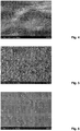
- Fig. 1 an SEM image of a surface region of the component is shown before the method according to the invention described above is carried out.
- Fig. 2 shows this surface after the method according to the invention has been carried out.
- the Ra value is reduced from 15 ⁇ m before to 3 ⁇ m after the post-treatment according to the invention.
- Example 2 Post-treatment of a 3D-printed component made of AlMgSi10
- a 3D-printed component made of the high silicon alloy AlMgSi10 is after mechanical cleaning and electrical contacting in an electrolyte consisting of 4.4% methanesulfonic acid, 45.6% phosphoric acid, 32.7% sulfuric acid, 4.5% triethanolamine, 0, 4% amino-tris (methylenephosphonic acid) and 12.4% ammonium hydrogen difluoride at a voltage of 18 V and a current density of 4 A / dm 2 for 40 minutes.
- the component is then rinsed with deionized water and dried using compressed air.
- Fig. 3 and Fig. 4 again show an SEM image of the surface of the component before or after the method according to the invention has been carried out, the determined Ra value decreasing from 1.4 ⁇ m to 0.3 ⁇ m.
- Example 3 Post-treatment of a 3D-printed component made of Ti6Al4V
- a 3D-printed component for technical applications made of the titanium alloy Ti6Al4V is removed from the 3D printer, mechanically pre-cleaned and electrically contacted.
- the component is then placed in an electrolyte bath consisting of 98% methanesulfonic acid, 1.5% amino-tris (methylenephosphonic acid) and 0.5% inositol at a temperature of 45 ° C, at an average voltage of 20 V and an average current density of 5 A / dm 2 treated with pulsed current for 30 minutes.
- the component is then rinsed with deionized water and dried using compressed air.
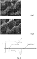
- Fig. 5 the surface of the component is shown, with an Ra value of 15 ⁇ m. After treating the component in the manner described above by the method according to the invention, the Ra value was only 3 ⁇ m. In Fig. 6 the smoothing of the surface of the component treated according to the invention is evident.
- Example 4 Post-treatment of a 3D-printed component made of Ti6Al4V
- a 3D-printed component for medical applications is placed in an electrolyte Consists of 90% methanesulfonic acid, 1.5% 1-hydroxyethane (1,1-diphosphonic acid), 3% amino-tris (methylenephosphonic acid) and 5.5% glycol at a voltage of 22 V and a current density of 10 A / dm 2 smoothed using direct current for 60 minutes.
- the component is then rinsed with deionized water and dried using compressed air.
- this component has a grid-like structure, the roughness of which is caused by powder residues from 3D printing adhering to the surface. After treatment using the method according to the invention, these particle residues are practically completely removed ( Fig. 8 ).
- a typical pulse sequence 100 which, according to the invention, consists of an anodic pulse 110, the current intensity j + of which has a steady rise 111 over time up to a predeterminable value J1.
- This anodic pulse 110 held for a certain time ⁇ t1 is superimposed with micropulses 112, that is to say multipulses with a higher frequency.
- This anodic pulse 110 is followed by a cathodic pulse 120 in a rectangular shape.
- This pulse sequence 100 which consists of anodic pulse 110 and cathodic pulse 120, is repeated until the desired removal and, associated therewith, the desired surface quality is achieved.
- the duration and level of the steady rise 111 namely the edge or ramp, is dependent on the initial roughness and the etching duration required as a result.
- the number and height of the micropulses 112 depend on the material.
- Example 5 Smoothing a component made of a titanium alloy (Ti6Al4V)
- the resulting surfaces meet the requirements for surface roughness for the given application; further processing is not necessary for this. Depending on the application, however, the surface can be further functionalized.
Landscapes
- Chemical & Material Sciences (AREA)
- Engineering & Computer Science (AREA)
- Materials Engineering (AREA)
- Chemical Kinetics & Catalysis (AREA)
- Electrochemistry (AREA)
- Metallurgy (AREA)
- Organic Chemistry (AREA)
- Manufacturing & Machinery (AREA)
- General Chemical & Material Sciences (AREA)
- Mechanical Engineering (AREA)
- Electrical Discharge Machining, Electrochemical Machining, And Combined Machining (AREA)
Description
- Die Erfindung betrifft einen Elektrolyt zum Elektropolieren von Metalloberflächen, insbesondere von mittels additivem Verfahren aus Metallpulver hergestellten Teilen, wobei der Elektrolyt Methansulfonsäure enthält, sowie ein Verfahren hierzu.
- Die additive Fertigung von Metallteilen ("3D-Druck") ist eine relativ neue Technologie, die auf Grund ihrer gegenüber herkömmlichen Fertigungsverfahren erheblich erweiterten Flexibilität im Design von Bauteilen immer häufiger eingesetzt wird. Das Prinzip dieses Fertigungsverfahrens ist, ein schichtweise aufgebrachtes Metallpulver mittels Laser oder Elektronenstrahl gesteuert zu sintern oder zu schmelzen. Am Ende befindet sich der fertige Bauteil eingebettet im Metallpulver.
- Die Oberflächen derart gefertigter Bauteile weisen prozessbedingt Welligkeiten und Rauigkeiten auf, die durch die Korngröße des eingesetzten Metallpulvers, durch die für den Aufbau verwendete Schichtdicke und durch die Strahlgeometrie des eingesetzten Energiestrahls bedingt sind. Dieser Umstand erschwert den praktischen Einsatz von derartig hergestellten Teilen in der Technik erheblich. Eine klassische mechanische Nachbearbeitung von 3D-gedruckten Teilen ist in der Regel entweder nicht wirtschaftlich oder auf Grund der komplexen Geometrie des Bauteils praktisch unmöglich durchzuführen.
- Elektropolierverfahren gemäß dem Stand der Technik sind zwar geeignet, Rauigkeiten im einstelligen bis zum niedrigen zweistelligen Mikrometerbereich einzuebnen (der Abtrag beträgt hier typischerweise 10 µm bis 40 µm), scheitern aber regelmäßig an den im 3D-Druck auftretenden Rauigkeiten, die bis in den Zehntelmillimeterbereich hineinreichen.
- Die
DE 10 2006 053 586 B3 beschreibt ein derartiges Elektropolierverfahren, bei dem ein Elektrolyt der eingangs erwähnten Art eingesetzt wird. - Es ist daher Aufgabe der Erfindung, die Nachteile der bekannten Elektropolierverfahren zu beseitigen und insbesondere einen Elektrolyten bereitzustellen, der eine Oberflächenbehandlung von mittels additivem Verfahren aus Metallpulver hergestellten Teilen erlaubt.
- Diese Aufgabe wird erfindungsgemäß durch einen Elektrolyten der eingangs erwähnten Art dadurch gelöst, dass zusätzlich zumindest eine Phosphonsäure in dem Elektrolyten enthalten ist.
- Der erfindungsgemäße Elektrolyt ist in der Lage, die großen Rauigkeiten, die beim 3D-Druck prozessbedingt entstehen, einzuebnen. Selbstverständlich kann der erfindungsgemäße Elektrolyt auch in der Nachbearbeitung von konventionell hergestellten Metallbauteilen eingesetzt werden. Er ist vor allem für die Nachbearbeitung von Bauteilen aus Titanlegierungen geeignet, bei geeigneter Variation der Zusammensetzung ist auch die Bearbeitung von Aluminiumlegierungen möglich.
- Erfindungsgemäß ist hierbei vorgesehen, dass die zumindest eine Phosphonsäure aus einer Gruppe gewählt ist, die Mono-, Di-, und/oder Polyphosphonsäuren, vorzugsweise Amino-tris(methylenphosphonsäure) oder Mischungen daraus enthält.
- Untersuchungen der Erfinder haben gezeigt, dass insbesondere bei Bauteilen aus Titanlegierungen ausgezeichnete Ergebnisse in deren verbleibenden Oberflächenrauigkeit erhalten werden, wenn die zumindest eine Phosphonsäure in einer Konzentration von 0,1 Gew% bis 10 Gew% enthalten ist.
- Von besonderem Vorteil insbesondere bei der Anwendung für 3D-Druckteilen ist, wenn zusätzlich zumindest ein mehrwertiger Alkohol, bevorzugterweise mit zumindest drei, besonders bevorzugt mehr als drei funktionellen Hydroxygruppen und/oder zumindest ein Polyalkohol in dem erfindungsgemäßen Elektrolyten enthalten ist, wobei der Alkohol vorzugsweise aus einer Gruppe gewählt ist, die Glykol, Glyzerin, Polyvinylalkohol, Inositol oder Sorbitol oder Mischungen daraus enthält. Es hat sich gezeigt, dass diese Alkohole als Komplexbildner, Netzmittel und Viskositätsmodifikator den Einebnungseffekt wesentlich beeinflussen. Insbesondere verstärkt sich dieser Effekt mit steigender Anzahl an funktionellen Hydroxygruppen des eingesetzten Alkohols. Auch können Mischungen von verschiedenen Alkoholen zum Einsatz kommen.
- Üblicherweise ist der zumindest eine Alkohol in einer Konzentration von bis zu 10 Gew% in dem erfindungsgemäßen Elektrolyten enthalten.
- Je nach Oberfläche und Material des zu behandelnden Bauteils sind weitere Zusätze in dem erfindungsgemäßen Elektrolyten enthalten. Hierbei kommen insbesondere weitere Zusätze zum Einsatz, die aus einer Gruppe ausgewählt sind, die Mineralsäuren, insbesondere Phosphorsäure und Schwefelsäure, Fluoride, insbesondere Ammoniumhydrogendifluorid, und Amine, insbesondere Ethanolamine und Isopropanolamine enthält. Hierbei sind die Mineralsäuren üblicherweise in einer Konzentration von bis zu 50 Gew%, die Fluoride in einer Konzentration von bis 20 Gew%, und die Amine in einer Konzentration von bis zu 15 Gew% in dem Elektrolyten enthalten.
- Der erfindungsgemäße Elektrolyt wird insbesondere zur Nachbearbeitung von mittels additivem Verfahren aus Metallpulver hergestellten Teilen insbesondere aus Titan- und Aluminiumlegierungen verwendet.
- Des Weiteren ist der erfindungsgemäße Elektrolyt insbesondere für ein Elektropolierverfahren für im 3D-Druck hergestellte Bauteile aus Metall geeignet, wobei zumindest ein zu bearbeitender Bauteil als erste Elektrode fungiert und zumindest zweite Elektrode als Gegenelektrode vorgesehen ist, und zumindest ein teilweiser Abtrag eines Bereichs der Bauteiloberfläche in einem Elektrolytbad mit dem erfindungsgemäßen Elektrolyt erfolgt. Hierbei wird erfindungsgemäß der Strom in Form von sich wiederholenden Pulssequenzen angelegt, wobei zumindest ein anodischer Puls vorgesehen ist, dessen Stromstärke im zeitlichen Verlauf einen stetigen Anstieg bis zu einem vorgebbaren Wert aufweist, wobei bevorzugterweise der Anstieg linear, nicht-linear oder exponentiell ist. Somit weist dieser anodische Puls keine wie im Stand der Technik übliche Rechtecksform auf, sondern seine Stromstärke erhöht sich im Zug der Pulsdauer, sodass kein sprunghafter, sondern ein stetiger Anstieg der Stromstärke in Form einer nichtlinearen Flanke oder linearen Rampe über die Pulsdauer erhalten wird.
- Die Pulsform, insbesondere die Anstiegs- und gegebenenfalls die Abfallgeschwindigkeit des Stroms sind für den zeitlichen Verlauf der Entstehung und des Abbaus des Polierfilms verantwortlich. Durch gezielte Steuerung des zeitlichen Verlaufs der Pulsflanke kann dieser wesentliche Teil des Polierprozesses optimal durchgeführt werden. Die Kontrolle über den zeitlichen Aufbaus des Polierfilms erlaubt es, die Bereiche Ätzung - Passivierung - Polieren während des Elektropolierens geplant und reproduzierbar zu durchlaufen und damit den Materialabtrag gezielt zu steuern. Bei Metallteilen mit hoher Rauheit kann so durch eine langsam ansteigende Rampe beziehungsweise einen Stufenpuls die Ätzphase verlängert werden und so sowohl die Prozesszeit verkürzt als auch das Ergebnis verbessert werden.
- In einer bevorzugten Ausführung der Erfindung weist der Puls anschließend an den Anstieg Mikropulse auf. Dabei werden auf den Puls, dem sogenannten Basispuls, höherfrequente Mikropulse "aufgesetzt". Diese Mikropulse haben den Effekt, dass der Polierprozess beschleunigt wird, weil diese Mikropulse an Spitzen und Kanten aufgrund der Feldlinienkonzentration an diesen Stellen überproportional stark wirken. Des Weiteren wird dadurch die örtliche Stromverteilung über das Werkstück als Funktion der Frequenz der Mikropulse beeinflusst, was wiederum wesentlich für die Glättungswirkung des erfindungsgemäßen Verfahrens ist.
- Da die elektrolytische Doppelschichtkapazität auf einer rauen und chemisch inhomogenen Oberfläche, wie sie beispielsweise bei einem 3D-gedruckten Teil üblicherweise vorliegt, lokal unterschiedliche Werte aufweist, ist die Verteilung des Stroms bei höheren Frequenzen anders als bei niedrigen. Der Grund liegt darin, dass der effektive Widerstand einer Kapazität mit steigender Frequenz des angelegten Stroms sinkt, sodass die höherfrequenten Anteile des Strompulses bevorzugt über Stellen mit hoher Kapazität fließen, während der niederfrequente Anteil durch die Bereiche mit niedrigem Polarisationswiderstand fließt. Somit kann die lokale Stromverteilung am Werkstück durch die Pulsform wesentlich beeinflusst werden.
- Erfindungsgemäß ist bevorzugterweise vorgesehen, dass sich an dem zumindest einen anodischen zumindest ein zweiter anodischer Puls anschließt, wobei der zumindest zweite Puls gleich oder unterschiedlich von dem ersten Puls ist, und vorzugsweise zumindest zwei aufeinander folgende anodischen Pulse und/oder Pulssequenzen durch eine Pulspause und/oder durch zumindest einen kathodischen Puls unterbrochen werden. Diese Pulssequenzen können gleiche oder unterschiedliche sich wiederholende Pulse aufweisen. Wesentlich hierbei ist, dass zumindest ein anodischer Puls den erfindungsgemäßen stetigen Anstieg aufweist.
- In einer weiteren Ausführung der Erfindung kann sich die Pulsfrequenz mit der Dauer des erfindungsgemäßen Verfahrens aufgrund der fortschreitenden Glättung des Bauteils verändern. Die Kontrolle der Frequenz ist hier eine weitere Einflussgröße zur Steuerung der Abtragsgeschwindigkeit bei inhomogener Ausgangsrauigkeit und liegt üblicherweise zwischen 0,2 - 2000 Hz.
- Insgesamt ist festzustellen, dass die Steuerung des Strom- bzw. Spannungssignals der Pulse sowie die Kontrolle der Pulslängen, Pulsflanken und Pulspausephasen eine Steuerung der Polierwirkung erlauben. Hierbei beruht die Wirkung der Pulsflanken zu einem Teil auf dem durch die Rampensteilheit kontrollierten zeitlichen Aufbau des wirksamen Polierfilms, andererseits auf dem unterschiedlichen Frequenzspektrum der verwendeten Pulse.
- Hierbei ist je nach Anwendung vorgesehen, dass die Pulse eine mittlere Stromdichte von 0,5 A/dm2 bis 30 A/dm2 und die Pulse und/oder die Pulspausen eine Pulslänge von 0,0005 s bis 5 s aufweisen.
- Des Weiteren kann der Elektrolyt zusätzliche Additive, insbesondere Netzmittel, Inhibitoren und/oder Komplexierungsmittel enthalten. Ebenso kann vorgesehen sein, dass der Elektrolyt oder das Werkstück periodisch oder kontinuierlich bewegt wird.
- In dem erfindungsgemäßen Verfahren ist insbesondere vorgesehen, dass als Gegenelektroden inerte Kathoden, insbesondere Stahlkathoden oder Edelstahlkathoden eingesetzt werden.
- Nachfolgend wird anhand von nicht-einschränkenden Ausführungsbeispielen die Erfindung näher erläutert. Hierin sind die Prozentangaben als Gewichtsprozent zu verstehen, sofern nicht anders angegeben.
- In Vorbereitung zur elektrochemischen Nachbearbeitung von 3D-gedruckten Teilen wird in einem ersten Schritt eine mechanische Reinigung, beispielsweise durch Strahlen oder Shotpeening durchgeführt, um lose anhaftendes, beziehungsweise in Hohlräumen und Hinterschneidungen angesammeltes, nicht mit dem Bauteil verbundenes Metallpulver zu entfernen.
- Nach diesem Reinigungsschritt wird der Bauteil an einer geeigneten Stelle mechanisch fixiert, elektrisch kontaktiert, in den erfindungsgemäßen Elektrolyten getaucht und anodisch nach einem auf das Material und die Bauteilgeometrie abgestimmten elektrochemischen Verfahren belastet.
- Die Konzentrationen der einzelnen Bestandteile des Elektrolyten werden hierbei derart eingestellt, dass eine vordefinierte Endrauigkeit der Bauteiloberfläche erreicht wird.
- Der verwendete Strom kann je nach Anforderung Gleichstrom, ein unipolarer Pulsstrom oder ein bipolarer Reverse Pulsstrom sein. Auch die Kombination von unterschiedlichen Verfahren ist möglich.
- Die Badtemperatur beträgt zwischen 20°C und 75°C und wird ebenfalls auf das zu behandelnde Werkstück abgestimmt.
- Eine Verbesserung der Ergebnisse wird erreicht, wenn eine Bewegung des Elektrolyten durch Pumpen und/oder Rühren vorgesehen ist, um eine effektive Elektrolytumwälzung an jenen Stellen zu erzielen, an denen der größte Abtrag erfolgen soll.
- Die Erfindung ist in den unabhängigen Ansprüchen 1, 8 und 10 definiert.
- Die folgenden Beispiele 1, 2 und 5 sind daher Vergleichsbeispiele und zeigen nicht die Erfindung.
- Ein 3D-gedruckter Bauteil für technische Anwendungen aus der Titanlegierung Ti6Al4V wird aus dem 3D-Drucker entnommen, mechanisch vorgereinigt und elektrisch kontaktiert. Anschließend wird der Bauteil in einem Elektrolytbad bestehend aus 98% Methansulfonsäure, 2% Amino-tris(methylenphosphonsäure) und bei einer Temperatur von 50°C, bei einer mittleren Spannung von 20 V und einer mittleren Stromdichte von 12,5 A/dm2 mittels Pulsstrom 30 Minuten lang behandelt. Anschließend wird der Bauteil mit entionisiertem Wasser gespült und mittels Pressluft getrocknet.
- In
Fig. 1 ist eine SEM-Aufnahme eines Oberflächenbereichs des Bauteils vor Durchführung des oben beschriebenen erfindungsgemäßen Verfahrens abgebildet.Fig. 2 zeigt diese Oberfläche nach Durchführung des erfindungsgemäßen Verfahrens. Hierbei reduziert sich der Ra-Wert von 15 µm vor auf 3 µm nach der erfindungsgemäßen Nachbehandlung. - Ein 3D-gedruckter Bauteil aus der hochsiliziumhältigen Legierung AlMgSi10 wird nach einer mechanischen Reinigung und der elektrischen Kontaktierung in einem Elektrolyt bestehend aus 4,4 % Methansulfonsäure, 45,6 % Phosphorsäure, 32,7 % Schwefelsäure, 4,5 % Triethanolamin, 0,4 % Amino-tris(methylenphosphonsäure) und 12,4 % Ammoniumhydrogendifluorid bei einer Spannung von 18 V und einer Stromdichte von 4 A/dm2 40 Minuten lang geglättet. Anschließend wird der Bauteil mit entionisiertem Wasser gespült und mittels Pressluft getrocknet.
-
Fig. 3 undFig. 4 zeigen wiederum eine SEM-Aufnahme der Oberfläche des Bauteils vor beziehungsweise nach Durchführung des erfindungsgemäßen Verfahrens, wobei der ermittelte Ra-Wert von 1,4 µm auf 0,3 µm abnahm. - Ein 3D-gedruckter Bauteil für technische Anwendungen aus der Titanlegierung Ti6Al4V wird aus dem 3D-Drucker entnommen, mechanisch vorgereinigt und elektrisch kontaktiert. Anschließend wird der Bauteil in einem Elektrolytbad bestehend aus 98 % Methansulfonsäure, 1,5 % Amino-tris(methylenphosphonsäure) und 0,5 % Inositol bei einer Temperatur von 45°C, bei einer mittleren Spannung von 20 V und einer mittleren Stromdichte von 5 A/dm2 mittels Pulsstrom 30 Minuten lang behandelt. Anschließend wird der Bauteil mit entionisiertem Wasser gespült und mittels Pressluft getrocknet.
- In
Fig. 5 ist die Oberfläche des Bauteils gezeigt, wobei diese einen Ra-Wert von 15 µm aufwies. Nach der Behandlung des Bauteils in der oben beschriebenen Weise nach dem erfindungsgemäßen Verfahren betrug der Ra-Wert lediglich 3 µm. InFig. 6 ist die Glättung der Oberfläche des erfindungsgemäß behandelten Bauteils augenscheinlich. - Ein 3D-gedruckter Bauteil für medizinische Anwendungen wird nach der mechanischen Reinigung und elektrischen Kontaktierung in einem Elektrolyten bestehend aus 90 % Methansulfonsäure, 1,5 % 1-Hydroxyethan-(1,1-diphosphonsäure), 3 % Amino-tris(methylenphosphonsäure) und 5,5 % Glykol bei einer Spannung von 22 V und einer Stromdichte von 10 A/dm2 mittels Gleichstrom 60 Minuten lang geglättet. Anschließend wird der Bauteil mit entionisiertem Wasser gespült und mittels Pressluft getrocknet.
- Wie in
Fig. 7 in einer SEM-Aufnahme der Oberfläche gezeigt, weist dieser Bauteil eine gitterartige Struktur auf, deren Rauigkeit durch an der Oberfläche anhaftende Pulverrückstände aus dem 3D-Druck verursacht wird. Nach der Behandlung mittels des erfindungsgemäßen Verfahrens sind diese Partikelrückstände praktisch vollständig entfernt (Fig. 8 ). - In der
Fig. 9 ist eine typische Pulssequenz 100 dargestellt, die gemäß der Erfindung aus einem anodischen Puls 110, dessen Stromstärke j+ im zeitlichen Verlauf einen stetigen Anstieg 111 bis zu einem vorgebbaren Wert J1 aufweist. Dieser über eine bestimmte Zeit Δt1 gehaltene anodische Puls 110 wird mit Mikropulsen 112, also Multipulse mit höherer Frequenz, überlagert. An diesen anodischen Puls 110 schließt ein kathodischer Puls 120 in Rechtecksform an. - Diese aus anodischem Puls 110 und kathodischem Puls 120 bestehende Pulssequenz 100 wird solange wiederholt, bis der gewünschte Abtrag und damit verbunden die gewünschte Oberflächengüte erzielt wird. Die Dauer und Höhe des stetigen Anstiegs 111, nämlich der Flanke bzw. Rampe ist von der Ausgangsrauigkeit und der daraus folgenden benötigten Ätzdauer abhängig. Die Anzahl und Höhe der Mikropulse 112 sind materialabhängig.
- Der 3D-gedruckte Bauteil mit Ausgangsrauigkeit von Ra = 20 µm aus einer Titanlegierung wird wie folgt behandelt:
- Reinigung des Bauteils, insbesondere Entfetten und Spülen
- Entgraten mittels elektrochemisch unterstütztem Ätzen und erneutes Spülen
- Glättung der Oberfläche des Bauteils mittels erfindungsgemäßen Verfahren:
- Der anodische Puls besteht hierbei aus einer Rampe mit einer Stromdichte von 0 bis 5 A/dm2 ansteigend und einem anschließenden Pulsmuster von 5 A/dm2 und 20 A/dm2 bei einer Frequenz von 2 Hz.
- Der Elektrolyt besteht aus:
- 98% Methansulfonsäure
- 1% Amino-tris(methylenphosphonsäure)
- 1% Wasser
- Die Temperatur des Elektrolytbades liegt bei 50°C
- Spülen
- Trocknen
- Die Rauigkeit des bearbeiteten Bauteils reduziert sich durch diese Oberflächenbehandlung auf Ra = 1,8 µm. Die resultierenden Oberflächen erfüllen die Anforderung hinsichtlich der Oberflächenrauigkeit für die gegebene Anwendung, eine weitere Bearbeitung ist dafür nicht erforderlich. Je nach Einsatz kann jedoch eine weitere Funktionalisierung der Oberfläche erfolgen.
Claims (15)
- Elektrolyt zum Elektropolieren von Metalloberflächen, wobei der Elektrolyt Methansulfonsäure, zumindest eine Phosphonsäure und zumindest einen mehrwertigen Alkohol und/oder zumindest einen Polyalkohol umfasst.
- Elektrolyt nach Anspruch 1, dadurch gekennzeichnet, dass die Phosphonsäure aus einer Gruppe gewählt ist, die aus Mono-, Di-, und/oder Polyphosphonsäuren, vorzugsweise Amino-tris(methylenphosphonsäure) oder Mischungen daraus besteht.
- Elektrolyt nach Anspruch 1 oder 2, dadurch gekennzeichnet, dass die zumindest eine Phosphonsäure in einer Konzentration von 0,1 Gew% bis 10 Gew% enthalten ist.
- Elektrolyt nach einem der Ansprüche 1 bis 3, dadurch gekennzeichnet, dass der Polyalkohol aus einer Gruppe gewählt ist, die aus Glykol, Glyzerin, Polyvinylalkohol, Inositol oder Sorbitol oder Mischungen daraus besteht.
- Elektrolyt nach Anspruch 4, dadurch gekennzeichnet, dass der zumindest eine Alkohol in einer Konzentration von bis 10 Gew% enthalten ist.
- Elektrolyt nach einem der Ansprüche 1 bis 5, dadurch gekennzeichnet, dass weitere Zusätze enthalten sind, die aus einer Gruppe ausgewählt sind, die aus
Mineralsäuren, insbesondere Phosphorsäure und Schwefelsäure in einer Konzentration von jeweils bis zu 50 Gew%,
Fluoriden, insbesondere Ammoniumdifluorid in einer Konzentration von bis 20 Gew%, und
Aminen, insbesondere Ethanolamine und Isopropanolamine in einer Konzentration von bis zu 15 Gew% besteht. - Elektrolyt nach einem der Ansprüche 1 bis 6, dadurch gekennzeichnet, dass der Elektrolyt zusätzliche Additive, insbesondere Netzmittel, Inhibitoren und/oder Komplexierungsmittel enthält.
- Verwendung eines Elektrolyten nach einem der Ansprüche 1 bis 7 in einem elektrochemischen Oberflächenverfahren zur Nachbearbeitung von mittels additivem Verfahren aus Metallpulver hergestellten Teilen, insbesondere aus Titan- und Aluminiumlegierungen.
- Verwendung eines Elektrolyten nach Anspruch 8, dadurch gekennzeichnet, dass die Nachbearbeitung in dem Elektrolyten mittels Gleichstrom, Wechselstrom, gepulstem Strom oder Pulse-Reverse-Strom erfolgt.
- Elektropolierverfahren, insbesondere für im 3D-Druck hergestellte Bauteile aus Metall, wobei zumindest ein zu bearbeitender Bauteil als erste Elektrode fungiert und zumindest zweite Elektrode als Gegenelektrode vorgesehen ist, und zumindest ein teilweiser Abtrag eines Bereichs der Bauteiloberfläche in einem Elektrolytbad mit einem Elektrolyt nach einem der Ansprüche 1 bis 7 durch Anlegen von Strom an dem Bauteil erfolgt, dadurch gekennzeichnet, dass der Strom in Form von sich wiederholenden Pulssequenzen (100) angelegt wird, wobei zumindest ein anodischer Puls (110) vorgesehen ist, dessen Stromstärke (j+) im zeitlichen Verlauf (t) einen stetigen Anstieg (111) bis zu einem vorgebbaren Wert (Jl) aufweist.
- Verfahren nach Anspruch 10, dadurch gekennzeichnet, dass der Anstieg (111) linear, nicht-linear oder exponentiell ist.
- Verfahren nach Anspruch 10 oder 11, dadurch gekennzeichnet, dass anschließend an den Anstieg (111) der anodische Puls (110) Mikropulse (112) aufweist.
- Verfahren nach einem der Ansprüche 10 bis 12, dadurch gekennzeichnet, dass sich an dem zumindest einen anodischen Puls (110) zumindest ein zweiter Puls (120) anschließt, wobei der zumindest zweite Puls (120) vorzugsweise unterschiedlich von dem ersten Puls (110) ist, und der zumindest erste Puls und der zumindest zweite Puls eine sich wiederholende Pulssequenz (100) bilden, die bevorzugterweise durch eine Pulspause und/oder durch zumindest einen kathodischen Puls (120) unterbrochen werden.
- Verfahren nach einem der Ansprüche 10 bis 13, dadurch gekennzeichnet, dass die Pulse (110, 120) eine mittlere Stromdichte von 0,5 A/dm2 bis 30 A/dm2 aufweisen.
- Verfahren nach einem der Ansprüche 10 bis 14, dadurch gekennzeichnet, dass die Pulse (110, 120) und/oder die Pulspausen eine Pulslänge von 0,0005 s bis 5 s aufweisen.
Applications Claiming Priority (3)
| Application Number | Priority Date | Filing Date | Title |
|---|---|---|---|
| ATA51119/2016A AT519430A1 (de) | 2016-12-09 | 2016-12-09 | Elektrochemisches pulspolieren |
| ATA50716/2017A AT520365B1 (de) | 2017-08-29 | 2017-08-29 | Elektrolyt zum elektropolieren von metalloberflächen |
| PCT/AT2017/060326 WO2018102845A1 (de) | 2016-12-09 | 2017-12-07 | Elektropolierverfahren und elektrolyt hierzu |
Publications (2)
| Publication Number | Publication Date |
|---|---|
| EP3551786A1 EP3551786A1 (de) | 2019-10-16 |
| EP3551786B1 true EP3551786B1 (de) | 2021-04-07 |
Family
ID=60702243
Family Applications (1)
| Application Number | Title | Priority Date | Filing Date |
|---|---|---|---|
| EP17816393.7A Active EP3551786B1 (de) | 2016-12-09 | 2017-12-07 | Elektropolierverfahren und elektrolyt hierzu |
Country Status (5)
| Country | Link |
|---|---|
| US (1) | US11549194B2 (de) |
| EP (1) | EP3551786B1 (de) |
| DK (1) | DK3551786T3 (de) |
| ES (1) | ES2879297T3 (de) |
| WO (1) | WO2018102845A1 (de) |
Cited By (1)
| Publication number | Priority date | Publication date | Assignee | Title |
|---|---|---|---|---|
| EP4438774A1 (de) | 2023-03-30 | 2024-10-02 | Centre de Recherches Métallurgiques ASBL - Centrum voor Research in de Metallurgie VZW | Gegenelektrode für elektrochemisches verfahren mit automatischer anpassung an die geometrie des zu behandelnden werkstücks |
Families Citing this family (4)
| Publication number | Priority date | Publication date | Assignee | Title |
|---|---|---|---|---|
| EP3640372A1 (de) | 2018-10-18 | 2020-04-22 | Hirtenberger Engineered Surfaces GmbH | Verfahren zum entfernen von metallischen stützstrukturen an einem additiv gefertigten metallbauteil |
| DE102019207864A1 (de) * | 2019-05-28 | 2020-12-03 | Trumpf Laser- Und Systemtechnik Gmbh | Verfahren zum additiven Herstellen von Bauteilen |
| EP4073294B1 (de) * | 2019-12-10 | 2024-01-03 | Biotronik Ag | Neuartiger elektrolyt für das elektropolieren von titanlegierungen |
| DE202022104389U1 (de) | 2021-09-09 | 2022-08-23 | Siemens Healthcare Gmbh | Effiziente Wärmeabfuhr über Gleitlager einer Drehanode |
Family Cites Families (21)
| Publication number | Priority date | Publication date | Assignee | Title |
|---|---|---|---|---|
| DE2412091C2 (de) | 1973-03-14 | 1983-09-01 | Mitsubishi Denki K.K., Tokyo | Verfahren und Vorrichtung zur Elektroerosionsbearbeitung |
| US3974357A (en) | 1973-03-22 | 1976-08-10 | Mitsubishi Denki Kabushiki Kaisha | Process and apparatus for electrical discharge shaping using sequential switching |
| DE3302011C1 (de) | 1983-01-21 | 1984-06-20 | Kraftwerk Union AG, 4330 Mülheim | Verfahren zum elektrolytischen Oberflächenpolieren von Fertigteilen aus Zirkon und/oder Zirkonlegierungen |
| DE3419945C1 (de) | 1984-05-11 | 1985-11-21 | Aktiengesellschaft für industrielle Elektronik AGIE Losone bei Locarno, Losone, Locarno | Impulsgenerator zur funkenerosiven Metallbearbeitung |
| US5126525A (en) | 1988-11-01 | 1992-06-30 | Sodick Co., Ltd. | Power supply system for electric discharge machines |
| US5147995A (en) | 1991-04-30 | 1992-09-15 | Industrial Technology Research Institute | Discharging circuit arrangement for an electrical discharging machine |
| US5539178A (en) | 1992-11-18 | 1996-07-23 | Mitsubishi Denki Kabushiki Kaisha | Method and apparatus for controlling the power supply for electrical discharge machine |
| TWI231831B (en) * | 2001-10-11 | 2005-05-01 | Shipley Co Llc | Stripping solution |
| DE10320909A1 (de) * | 2003-05-09 | 2004-11-18 | Poligrat Holding Gmbh | Elektrolyt zum elektrochemischen Polieren von Metalloberflächen |
| US9399618B2 (en) * | 2003-05-12 | 2016-07-26 | Arkema Inc. | High purity electrolytic sulfonic acid solutions |
| DE102006045221B3 (de) | 2006-09-25 | 2008-04-03 | Poligrat Gmbh | Elektropolierverfahren für Kobalt und Kobaltlegierungen und Elektrolyt |
| DE102006047713B3 (de) | 2006-10-09 | 2008-03-27 | Poligrat Gmbh | Elektropolierverfahren für Niob und Tantal und Elektrolyt |
| DE102006050317B3 (de) | 2006-10-25 | 2008-06-19 | Poligrat Gmbh | Elektrolyt zum Elektropolieren von Edelstahl (Eisen-Chrom- und Chrom-Eisen-Legierungen) und Elektropolierverfahren für Edelstahl |
| DE102006053586B3 (de) | 2006-11-14 | 2008-04-17 | Poligrat Gmbh | Elektropolierverfahren |
| US8021491B2 (en) * | 2006-12-07 | 2011-09-20 | Lawrence Bernard Kool | Method for selectively removing coatings from metal substrates |
| DE102007011632B3 (de) | 2007-03-09 | 2008-06-26 | Poligrat Gmbh | Elektropolierverfahren für Titan |
| JP4874358B2 (ja) | 2009-02-27 | 2012-02-15 | 株式会社ソディック | 形彫放電加工装置の加工用電源装置 |
| US20110303553A1 (en) | 2010-06-11 | 2011-12-15 | Inman Maria E | Electrochemical system and method for machining strongly passivating metals |
| US8617380B2 (en) * | 2011-10-12 | 2013-12-31 | Abbott Cardiovascular Systems, Inc. | Electropolishing solution containing a water sequestering agent and methods of use thereof |
| EP2878713A1 (de) | 2013-11-28 | 2015-06-03 | Abbott Laboratories Vascular Enterprises Limited | Elektrolytzusammensetzung und Verfahren zur Elektropolierbehandlung von Nickel-Titan-Legierungen und/oder anderen Metallsubstraten mit Wolfram-, Niob- und Tantallegierungen |
| US10522850B2 (en) | 2014-09-30 | 2019-12-31 | The Government Of The United States Of America, As Represented By The Secretary Of The Navy | Three-dimensionally printed bipolar plate for a proton exchange membrane fuel cell |
-
2017
- 2017-12-07 WO PCT/AT2017/060326 patent/WO2018102845A1/de not_active Ceased
- 2017-12-07 EP EP17816393.7A patent/EP3551786B1/de active Active
- 2017-12-07 US US16/467,206 patent/US11549194B2/en active Active
- 2017-12-07 ES ES17816393T patent/ES2879297T3/es active Active
- 2017-12-07 DK DK17816393.7T patent/DK3551786T3/da active
Non-Patent Citations (1)
| Title |
|---|
| None * |
Cited By (1)
| Publication number | Priority date | Publication date | Assignee | Title |
|---|---|---|---|---|
| EP4438774A1 (de) | 2023-03-30 | 2024-10-02 | Centre de Recherches Métallurgiques ASBL - Centrum voor Research in de Metallurgie VZW | Gegenelektrode für elektrochemisches verfahren mit automatischer anpassung an die geometrie des zu behandelnden werkstücks |
Also Published As
| Publication number | Publication date |
|---|---|
| US20200080222A1 (en) | 2020-03-12 |
| WO2018102845A1 (de) | 2018-06-14 |
| ES2879297T3 (es) | 2021-11-22 |
| US11549194B2 (en) | 2023-01-10 |
| EP3551786A1 (de) | 2019-10-16 |
| DK3551786T3 (da) | 2021-06-28 |
Similar Documents
| Publication | Publication Date | Title |
|---|---|---|
| EP3551786B1 (de) | Elektropolierverfahren und elektrolyt hierzu | |
| EP3551787B1 (de) | Elektropolierverfahren und anlage hierzu | |
| DE69608579T2 (de) | Elektrolytisches verfahren zur reinigung von elektrisch leitenden oberflächen | |
| DE102017006205B4 (de) | Verfahren zum Glätten eines generativ gefertigten Bauteils | |
| EP0722515B1 (de) | Verfahren zum galvanischen aufbringen einer oberflächenbeschichtung | |
| AT520365B1 (de) | Elektrolyt zum elektropolieren von metalloberflächen | |
| DE102010013415B4 (de) | Beschichtung aus anodischem Oxid und Verfahren zum anodischen Oxidieren | |
| DE102008012596B4 (de) | Kontinuierliches Verfahren und Vorrichtung zur elektrolytischen Bearbeitung von metallischen Werkstücken | |
| WO2017212051A1 (de) | Verfahren und vorrichtung zur herstellung von zügen in läufen von feuerwaffen | |
| DE69203408T2 (de) | Antikorrosionsvorrichtung fur elektroentladungsbearbeiten. | |
| EP2237914B1 (de) | Verfahren zur bearbeitung eines metallischen bauteils | |
| WO2020079245A1 (de) | Verfahren zum entfernen von metallischen stützstrukturen an einem additiv gefertigten metallbauteil | |
| EP2105236A1 (de) | Verfahren zur funkenerosiven Bearbeitung eines mit einner elektrisch nicht leitenden Beschichtung versehenen elektrisch leitfähigen Bauteils | |
| DE102007062559A1 (de) | Verfahren zur Herstellung und Reparatur eines Bauteils und Bauteil einer Gasturbine | |
| DE102019216048A1 (de) | Verfahren und Elektrode zum Bearbeiten von Bauteilen durch elektrochemisches Abtragen | |
| EP3875636A1 (de) | Verfahren zur plasmaelektrolytischen oxidation eines metallsubstrats | |
| EP2461933B1 (de) | Verfahren zur elektrochemischen bearbeitung eines werkstückes | |
| DE3624695A1 (de) | Anordnung zur elektrolytischen behandlung profilierter werkstuecke | |
| DE885333C (de) | Verfahren zur elektrochemischen Behandlung von Metallkoerpern zwecks Abtragens von Oberflaechenschichten | |
| DE102019204979A1 (de) | Verfahren zur Herstellung einer Komponente für EUV-Lithographievorrichtungen | |
| EP1473387A1 (de) | Verfahren zur Entschichtung eines Bauteils | |
| DE2854605C2 (de) | ||
| DE102015103224A1 (de) | Verfahren zur elektrochemischen Bearbeitung eines Werkstückes | |
| DE2624070A1 (de) | Verfahren zum elektrochemischen bohren | |
| EP4144468A1 (de) | Fertigungsvorrichtung zum elektrochemischen bearbeiten eines bauteils, insbesondere eines turbinenbauteils, verfahren zum elektrochemischen bearbeiten eines bauteils und bauteil |
Legal Events
| Date | Code | Title | Description |
|---|---|---|---|
| STAA | Information on the status of an ep patent application or granted ep patent |
Free format text: STATUS: UNKNOWN |
|
| STAA | Information on the status of an ep patent application or granted ep patent |
Free format text: STATUS: THE INTERNATIONAL PUBLICATION HAS BEEN MADE |
|
| PUAI | Public reference made under article 153(3) epc to a published international application that has entered the european phase |
Free format text: ORIGINAL CODE: 0009012 |
|
| STAA | Information on the status of an ep patent application or granted ep patent |
Free format text: STATUS: REQUEST FOR EXAMINATION WAS MADE |
|
| 17P | Request for examination filed |
Effective date: 20190709 |
|
| AK | Designated contracting states |
Kind code of ref document: A1 Designated state(s): AL AT BE BG CH CY CZ DE DK EE ES FI FR GB GR HR HU IE IS IT LI LT LU LV MC MK MT NL NO PL PT RO RS SE SI SK SM TR |
|
| AX | Request for extension of the european patent |
Extension state: BA ME |
|
| DAV | Request for validation of the european patent (deleted) | ||
| DAX | Request for extension of the european patent (deleted) | ||
| GRAP | Despatch of communication of intention to grant a patent |
Free format text: ORIGINAL CODE: EPIDOSNIGR1 |
|
| STAA | Information on the status of an ep patent application or granted ep patent |
Free format text: STATUS: GRANT OF PATENT IS INTENDED |
|
| INTG | Intention to grant announced |
Effective date: 20201008 |
|
| GRAS | Grant fee paid |
Free format text: ORIGINAL CODE: EPIDOSNIGR3 |
|
| GRAA | (expected) grant |
Free format text: ORIGINAL CODE: 0009210 |
|
| STAA | Information on the status of an ep patent application or granted ep patent |
Free format text: STATUS: THE PATENT HAS BEEN GRANTED |
|
| AK | Designated contracting states |
Kind code of ref document: B1 Designated state(s): AL AT BE BG CH CY CZ DE DK EE ES FI FR GB GR HR HU IE IS IT LI LT LU LV MC MK MT NL NO PL PT RO RS SE SI SK SM TR |
|
| RAP1 | Party data changed (applicant data changed or rights of an application transferred) |
Owner name: RENA TECHNOLOGIES AUSTRIA GMBH |
|
| REG | Reference to a national code |
Ref country code: GB Ref legal event code: FG4D Free format text: NOT ENGLISH |
|
| REG | Reference to a national code |
Ref country code: AT Ref legal event code: REF Ref document number: 1379801 Country of ref document: AT Kind code of ref document: T Effective date: 20210415 Ref country code: CH Ref legal event code: EP |
|
| REG | Reference to a national code |
Ref country code: DE Ref legal event code: R096 Ref document number: 502017010033 Country of ref document: DE |
|
| REG | Reference to a national code |
Ref country code: IE Ref legal event code: FG4D Free format text: LANGUAGE OF EP DOCUMENT: GERMAN |
|
| REG | Reference to a national code |
Ref country code: NL Ref legal event code: FP |
|
| REG | Reference to a national code |
Ref country code: DK Ref legal event code: T3 Effective date: 20210624 |
|
| REG | Reference to a national code |
Ref country code: SE Ref legal event code: TRGR |
|
| REG | Reference to a national code |
Ref country code: LT Ref legal event code: MG9D |
|
| PG25 | Lapsed in a contracting state [announced via postgrant information from national office to epo] |
Ref country code: LT Free format text: LAPSE BECAUSE OF FAILURE TO SUBMIT A TRANSLATION OF THE DESCRIPTION OR TO PAY THE FEE WITHIN THE PRESCRIBED TIME-LIMIT Effective date: 20210407 Ref country code: FI Free format text: LAPSE BECAUSE OF FAILURE TO SUBMIT A TRANSLATION OF THE DESCRIPTION OR TO PAY THE FEE WITHIN THE PRESCRIBED TIME-LIMIT Effective date: 20210407 Ref country code: BG Free format text: LAPSE BECAUSE OF FAILURE TO SUBMIT A TRANSLATION OF THE DESCRIPTION OR TO PAY THE FEE WITHIN THE PRESCRIBED TIME-LIMIT Effective date: 20210707 Ref country code: HR Free format text: LAPSE BECAUSE OF FAILURE TO SUBMIT A TRANSLATION OF THE DESCRIPTION OR TO PAY THE FEE WITHIN THE PRESCRIBED TIME-LIMIT Effective date: 20210407 |
|
| REG | Reference to a national code |
Ref country code: ES Ref legal event code: FG2A Ref document number: 2879297 Country of ref document: ES Kind code of ref document: T3 Effective date: 20211122 |
|
| PG25 | Lapsed in a contracting state [announced via postgrant information from national office to epo] |
Ref country code: GR Free format text: LAPSE BECAUSE OF FAILURE TO SUBMIT A TRANSLATION OF THE DESCRIPTION OR TO PAY THE FEE WITHIN THE PRESCRIBED TIME-LIMIT Effective date: 20210708 Ref country code: IS Free format text: LAPSE BECAUSE OF FAILURE TO SUBMIT A TRANSLATION OF THE DESCRIPTION OR TO PAY THE FEE WITHIN THE PRESCRIBED TIME-LIMIT Effective date: 20210807 Ref country code: RS Free format text: LAPSE BECAUSE OF FAILURE TO SUBMIT A TRANSLATION OF THE DESCRIPTION OR TO PAY THE FEE WITHIN THE PRESCRIBED TIME-LIMIT Effective date: 20210407 Ref country code: NO Free format text: LAPSE BECAUSE OF FAILURE TO SUBMIT A TRANSLATION OF THE DESCRIPTION OR TO PAY THE FEE WITHIN THE PRESCRIBED TIME-LIMIT Effective date: 20210707 Ref country code: LV Free format text: LAPSE BECAUSE OF FAILURE TO SUBMIT A TRANSLATION OF THE DESCRIPTION OR TO PAY THE FEE WITHIN THE PRESCRIBED TIME-LIMIT Effective date: 20210407 Ref country code: PT Free format text: LAPSE BECAUSE OF FAILURE TO SUBMIT A TRANSLATION OF THE DESCRIPTION OR TO PAY THE FEE WITHIN THE PRESCRIBED TIME-LIMIT Effective date: 20210809 Ref country code: PL Free format text: LAPSE BECAUSE OF FAILURE TO SUBMIT A TRANSLATION OF THE DESCRIPTION OR TO PAY THE FEE WITHIN THE PRESCRIBED TIME-LIMIT Effective date: 20210407 |
|
| REG | Reference to a national code |
Ref country code: DE Ref legal event code: R097 Ref document number: 502017010033 Country of ref document: DE |
|
| PG25 | Lapsed in a contracting state [announced via postgrant information from national office to epo] |
Ref country code: CZ Free format text: LAPSE BECAUSE OF FAILURE TO SUBMIT A TRANSLATION OF THE DESCRIPTION OR TO PAY THE FEE WITHIN THE PRESCRIBED TIME-LIMIT Effective date: 20210407 Ref country code: EE Free format text: LAPSE BECAUSE OF FAILURE TO SUBMIT A TRANSLATION OF THE DESCRIPTION OR TO PAY THE FEE WITHIN THE PRESCRIBED TIME-LIMIT Effective date: 20210407 Ref country code: RO Free format text: LAPSE BECAUSE OF FAILURE TO SUBMIT A TRANSLATION OF THE DESCRIPTION OR TO PAY THE FEE WITHIN THE PRESCRIBED TIME-LIMIT Effective date: 20210407 Ref country code: SK Free format text: LAPSE BECAUSE OF FAILURE TO SUBMIT A TRANSLATION OF THE DESCRIPTION OR TO PAY THE FEE WITHIN THE PRESCRIBED TIME-LIMIT Effective date: 20210407 Ref country code: SM Free format text: LAPSE BECAUSE OF FAILURE TO SUBMIT A TRANSLATION OF THE DESCRIPTION OR TO PAY THE FEE WITHIN THE PRESCRIBED TIME-LIMIT Effective date: 20210407 |
|
| PGFP | Annual fee paid to national office [announced via postgrant information from national office to epo] |
Ref country code: DK Payment date: 20211220 Year of fee payment: 5 |
|
| PLBE | No opposition filed within time limit |
Free format text: ORIGINAL CODE: 0009261 |
|
| STAA | Information on the status of an ep patent application or granted ep patent |
Free format text: STATUS: NO OPPOSITION FILED WITHIN TIME LIMIT |
|
| PGFP | Annual fee paid to national office [announced via postgrant information from national office to epo] |
Ref country code: CH Payment date: 20211222 Year of fee payment: 5 Ref country code: BE Payment date: 20211217 Year of fee payment: 5 |
|
| 26N | No opposition filed |
Effective date: 20220110 |
|
| PG25 | Lapsed in a contracting state [announced via postgrant information from national office to epo] |
Ref country code: IS Free format text: LAPSE BECAUSE OF FAILURE TO SUBMIT A TRANSLATION OF THE DESCRIPTION OR TO PAY THE FEE WITHIN THE PRESCRIBED TIME-LIMIT Effective date: 20210807 Ref country code: AL Free format text: LAPSE BECAUSE OF FAILURE TO SUBMIT A TRANSLATION OF THE DESCRIPTION OR TO PAY THE FEE WITHIN THE PRESCRIBED TIME-LIMIT Effective date: 20210407 |
|
| PG25 | Lapsed in a contracting state [announced via postgrant information from national office to epo] |
Ref country code: MC Free format text: LAPSE BECAUSE OF FAILURE TO SUBMIT A TRANSLATION OF THE DESCRIPTION OR TO PAY THE FEE WITHIN THE PRESCRIBED TIME-LIMIT Effective date: 20210407 |
|
| PG25 | Lapsed in a contracting state [announced via postgrant information from national office to epo] |
Ref country code: LU Free format text: LAPSE BECAUSE OF NON-PAYMENT OF DUE FEES Effective date: 20211207 Ref country code: IE Free format text: LAPSE BECAUSE OF NON-PAYMENT OF DUE FEES Effective date: 20211207 |
|
| PG25 | Lapsed in a contracting state [announced via postgrant information from national office to epo] |
Ref country code: CY Free format text: LAPSE BECAUSE OF FAILURE TO SUBMIT A TRANSLATION OF THE DESCRIPTION OR TO PAY THE FEE WITHIN THE PRESCRIBED TIME-LIMIT Effective date: 20210407 |
|
| REG | Reference to a national code |
Ref country code: DK Ref legal event code: EBP Effective date: 20221231 |
|
| PG25 | Lapsed in a contracting state [announced via postgrant information from national office to epo] |
Ref country code: HU Free format text: LAPSE BECAUSE OF FAILURE TO SUBMIT A TRANSLATION OF THE DESCRIPTION OR TO PAY THE FEE WITHIN THE PRESCRIBED TIME-LIMIT; INVALID AB INITIO Effective date: 20171207 |
|
| REG | Reference to a national code |
Ref country code: CH Ref legal event code: PL |
|
| REG | Reference to a national code |
Ref country code: BE Ref legal event code: MM Effective date: 20221231 |
|
| PG25 | Lapsed in a contracting state [announced via postgrant information from national office to epo] |
Ref country code: LI Free format text: LAPSE BECAUSE OF NON-PAYMENT OF DUE FEES Effective date: 20221231 Ref country code: CH Free format text: LAPSE BECAUSE OF NON-PAYMENT OF DUE FEES Effective date: 20221231 |
|
| PG25 | Lapsed in a contracting state [announced via postgrant information from national office to epo] |
Ref country code: BE Free format text: LAPSE BECAUSE OF NON-PAYMENT OF DUE FEES Effective date: 20221231 |
|
| PGFP | Annual fee paid to national office [announced via postgrant information from national office to epo] |
Ref country code: GB Payment date: 20231220 Year of fee payment: 7 |
|
| PG25 | Lapsed in a contracting state [announced via postgrant information from national office to epo] |
Ref country code: DK Free format text: LAPSE BECAUSE OF NON-PAYMENT OF DUE FEES Effective date: 20221231 |
|
| PGFP | Annual fee paid to national office [announced via postgrant information from national office to epo] |
Ref country code: SE Payment date: 20231219 Year of fee payment: 7 Ref country code: NL Payment date: 20231219 Year of fee payment: 7 Ref country code: AT Payment date: 20231213 Year of fee payment: 7 |
|
| PG25 | Lapsed in a contracting state [announced via postgrant information from national office to epo] |
Ref country code: MK Free format text: LAPSE BECAUSE OF FAILURE TO SUBMIT A TRANSLATION OF THE DESCRIPTION OR TO PAY THE FEE WITHIN THE PRESCRIBED TIME-LIMIT Effective date: 20210407 |
|
| PGFP | Annual fee paid to national office [announced via postgrant information from national office to epo] |
Ref country code: IT Payment date: 20231229 Year of fee payment: 7 |
|
| PG25 | Lapsed in a contracting state [announced via postgrant information from national office to epo] |
Ref country code: TR Free format text: LAPSE BECAUSE OF FAILURE TO SUBMIT A TRANSLATION OF THE DESCRIPTION OR TO PAY THE FEE WITHIN THE PRESCRIBED TIME-LIMIT Effective date: 20210407 |
|
| PG25 | Lapsed in a contracting state [announced via postgrant information from national office to epo] |
Ref country code: MT Free format text: LAPSE BECAUSE OF FAILURE TO SUBMIT A TRANSLATION OF THE DESCRIPTION OR TO PAY THE FEE WITHIN THE PRESCRIBED TIME-LIMIT Effective date: 20210407 |
|
| REG | Reference to a national code |
Ref country code: SE Ref legal event code: EUG |
|
| REG | Reference to a national code |
Ref country code: NL Ref legal event code: MM Effective date: 20250101 |
|
| REG | Reference to a national code |
Ref country code: AT Ref legal event code: MM01 Ref document number: 1379801 Country of ref document: AT Kind code of ref document: T Effective date: 20241207 |
|
| GBPC | Gb: european patent ceased through non-payment of renewal fee |
Effective date: 20241207 |
|
| PG25 | Lapsed in a contracting state [announced via postgrant information from national office to epo] |
Ref country code: NL Free format text: LAPSE BECAUSE OF NON-PAYMENT OF DUE FEES Effective date: 20250101 |
|
| PG25 | Lapsed in a contracting state [announced via postgrant information from national office to epo] |
Ref country code: IT Free format text: LAPSE BECAUSE OF NON-PAYMENT OF DUE FEES Effective date: 20241207 |
|
| PG25 | Lapsed in a contracting state [announced via postgrant information from national office to epo] |
Ref country code: GB Free format text: LAPSE BECAUSE OF NON-PAYMENT OF DUE FEES Effective date: 20241207 |
|
| PG25 | Lapsed in a contracting state [announced via postgrant information from national office to epo] |
Ref country code: AT Free format text: LAPSE BECAUSE OF NON-PAYMENT OF DUE FEES Effective date: 20241207 |
|
| PGFP | Annual fee paid to national office [announced via postgrant information from national office to epo] |
Ref country code: FR Payment date: 20251218 Year of fee payment: 9 |
|
| PGFP | Annual fee paid to national office [announced via postgrant information from national office to epo] |
Ref country code: ES Payment date: 20260119 Year of fee payment: 9 |
|
| PGFP | Annual fee paid to national office [announced via postgrant information from national office to epo] |
Ref country code: DE Payment date: 20251222 Year of fee payment: 9 |