EP3551501B1 - Wärmeableitungsvorrichtung für eine multimedia-steuereinheit - Google Patents
Wärmeableitungsvorrichtung für eine multimedia-steuereinheit Download PDFInfo
- Publication number
- EP3551501B1 EP3551501B1 EP17825140.1A EP17825140A EP3551501B1 EP 3551501 B1 EP3551501 B1 EP 3551501B1 EP 17825140 A EP17825140 A EP 17825140A EP 3551501 B1 EP3551501 B1 EP 3551501B1
- Authority
- EP
- European Patent Office
- Prior art keywords
- plate
- printed circuit
- circuit board
- heat dissipation
- dissipation device
- Prior art date
- Legal status (The legal status is an assumption and is not a legal conclusion. Google has not performed a legal analysis and makes no representation as to the accuracy of the status listed.)
- Active
Links
Images


Classifications
-
- H—ELECTRICITY
- H05—ELECTRIC TECHNIQUES NOT OTHERWISE PROVIDED FOR
- H05K—PRINTED CIRCUITS; CASINGS OR CONSTRUCTIONAL DETAILS OF ELECTRIC APPARATUS; MANUFACTURE OF ASSEMBLAGES OF ELECTRICAL COMPONENTS
- H05K7/00—Constructional details common to different types of electric apparatus
- H05K7/20—Modifications to facilitate cooling, ventilating, or heating
- H05K7/2039—Modifications to facilitate cooling, ventilating, or heating characterised by the heat transfer by conduction from the heat generating element to a dissipating body
- H05K7/20509—Multiple-component heat spreaders; Multi-component heat-conducting support plates; Multi-component non-closed heat-conducting structures
-
- H—ELECTRICITY
- H05—ELECTRIC TECHNIQUES NOT OTHERWISE PROVIDED FOR
- H05K—PRINTED CIRCUITS; CASINGS OR CONSTRUCTIONAL DETAILS OF ELECTRIC APPARATUS; MANUFACTURE OF ASSEMBLAGES OF ELECTRICAL COMPONENTS
- H05K7/00—Constructional details common to different types of electric apparatus
- H05K7/20—Modifications to facilitate cooling, ventilating, or heating
- H05K7/20845—Modifications to facilitate cooling, ventilating, or heating for automotive electronic casings
- H05K7/20863—Forced ventilation, e.g. on heat dissipaters coupled to components
-
- F—MECHANICAL ENGINEERING; LIGHTING; HEATING; WEAPONS; BLASTING
- F28—HEAT EXCHANGE IN GENERAL
- F28F—DETAILS OF HEAT-EXCHANGE AND HEAT-TRANSFER APPARATUS, OF GENERAL APPLICATION
- F28F13/00—Arrangements for modifying heat-transfer, e.g. increasing, decreasing
-
- H—ELECTRICITY
- H05—ELECTRIC TECHNIQUES NOT OTHERWISE PROVIDED FOR
- H05K—PRINTED CIRCUITS; CASINGS OR CONSTRUCTIONAL DETAILS OF ELECTRIC APPARATUS; MANUFACTURE OF ASSEMBLAGES OF ELECTRICAL COMPONENTS
- H05K7/00—Constructional details common to different types of electric apparatus
- H05K7/20—Modifications to facilitate cooling, ventilating, or heating
- H05K7/20009—Modifications to facilitate cooling, ventilating, or heating using a gaseous coolant in electronic enclosures
- H05K7/20136—Forced ventilation, e.g. by fans
- H05K7/20172—Fan mounting or fan specifications
-
- H—ELECTRICITY
- H05—ELECTRIC TECHNIQUES NOT OTHERWISE PROVIDED FOR
- H05K—PRINTED CIRCUITS; CASINGS OR CONSTRUCTIONAL DETAILS OF ELECTRIC APPARATUS; MANUFACTURE OF ASSEMBLAGES OF ELECTRICAL COMPONENTS
- H05K7/00—Constructional details common to different types of electric apparatus
- H05K7/20—Modifications to facilitate cooling, ventilating, or heating
- H05K7/2039—Modifications to facilitate cooling, ventilating, or heating characterised by the heat transfer by conduction from the heat generating element to a dissipating body
- H05K7/20409—Outer radiating structures on heat dissipating housings, e.g. fins integrated with the housing
Definitions
- the invention relates to the field of automobile multimedia electronic control units. More particularly, the invention relates to a heat dissipation device for a multimedia electronic control unit.
- the electronic multimedia control units on board the automobile generally comprise a metal casing provided with numerous electronic interface connectors.
- the metal casing generally comprises electronic modules arranged in metal racks arranged parallel next to each other.
- Each electronic module is generally dedicated to a multimedia function such as sound compression or decompression, video film compression or decompression, sound amplification, reception and processing of signals from a navigation system, reception and demodulation of radio signals, wireless communication interface between the vehicle and portable equipment, telephony interface...
- Each metal rack has a metal structure comprising thin fins in order to serve as a heat dissipation device for their respective electronic module.
- the metal casing also generally includes openings allowing the heat dissipated by the metal racks to be evacuated. It is also known to facilitate the extraction of hot air from the electronic modules using a fan arranged in the metal casing and facing openings of the metal casing.
- the metal structure also makes it possible to respond to the constraints of electromagnetic interference between the electronic modules and also to the constraints of radio frequency interference external to the multimedia control unit.
- the known multimedia control units are therefore bulky, heavy and complex to assemble. Their current structure does not meet the current requirements for reducing weight and also volume for current and future vehicles.
- EP 1885169 A1 discloses an air cooling device for an electronic device
- US6466641 B1 discloses a device for cooling an electronic part arranged in a PC server or a UNIX server
- US2016/139878 A1 discloses heat sink and component carrier assemblies.
- a heat dissipation device comprises a generally rectangular metal cooling plate, the metal plate comprising on its upper face first means for fixing a first printed circuit board provided for resting at least one heat-generating zone of the first printed circuit board on the upper side of the tray.
- the metal plate comprises on its underside second means for fixing a second printed circuit board provided for resting at least one heat-generating zone of the second printed circuit board on the underside of the plate.
- the upper face of the plate may comprise a first section equipped with a plurality of vertical cooling fins each extending in a longitudinal direction substantially parallel to one side of the plate; the first section comprising part of the first fixing means so as to allow the support of a heat-generating zone of the first printed circuit board on cooling fins.
- the underside of the first section may comprise at least one flat cooling surface forming a protuberance on said underside, so as to allow the support of a heat-generating zone of the second printed circuit board on the flat surface cooling.
- the first section may comprise a flat cooling zone extending transversely over the top of at least two fins so as to allow the support of a heat-generating zone of the first printed circuit board on the flat cooling zone .
- the first section may comprise at least one solid vertical cylindrical pad molded into a cooling fin so as to allow the support of a heat-generating zone of the first printed circuit board on the free end of the solid cylindrical pad.
- the first section forms a rectangular recess in the top face of the tray, forming a rectangular protuberance on the underside of the tray.
- the underside of the first section may comprise part of the second fixing means so as to allow the support of at least one heat-generating zone of the second printed circuit board on the underside of the first section.
- the tray may include at least three metal pillars extending vertically downward from the underside of the tray.
- the lower end of each pillar can be provided with a fixing means intended to be fixed to a bottom of the case so as to maintain the raised plate in order to arrange the second printed circuit board on the underside of the plate.
- a transverse side of the plate may include a fan support able to receive a fan making it possible to create a flow of air for cooling the plate in a longitudinal direction.
- the plate may include deflectors arranged between the fan support and the first section capable of guiding the flow of cooling air.
- the tray may include an opening between the first section and the fan support, so as to promote airflow on both sides of the tray.
- the plate may comprise an electrical connection element comprising two flexible contact ends, the first end being provided to establish an electrical contact by compression between the cooling plate and an electrically conductive element of the first printed circuit board or of the second board. printed circuit board; the second end being provided to establish an electrical contact by compression between the plate and a metal casing enclosing the heat dissipation device; so as to thermally and electromagnetically protect the electrically conductive element.
- the electrical connection element may comprise an intermediate part by which the connection element is fixed to the plate, the intermediate part being extended on one side by the first flexible end mainly in a direction perpendicular to the plate, and from the other side by the second flexible end mainly following a direction coplanar with the plate.
- the heat sink device can be made from a single piece of metal.
- an electronic assembly comprises the heat dissipation device described above, a first generally rectangular printed circuit board comprising a heat-generating zone resting on the upper face of the cooling plate; a second circuit board generally rectangular print comprising a heat-generating zone resting on the underside of the cooling plate.
- the electronic assembly may include a closed metal casing of generally rectangular parallelepipedal shape; the heat dissipation device being fixed in the bottom of the case.
- the casing may comprise a first group of openings arranged on a first side face of the casing and facing the cooling plate.
- the casing may also comprise a second group of openings arranged on a second lateral face of the casing opposite to the first face and facing the cooling plate so as to allow the circulation of a flow of cooling air. from the first group of apertures to the second group of apertures.
- a fan can be mounted in the fan support and can be arranged in the housing opposite one of the two groups of openings so as to facilitate the circulation of the flow of cooling air.
- the plate may include an electrical connection element. At least one of the printed circuit boards comprises a conductive element, the conductive element being in electrical contact via the electrical connection element with the plate and the metal casing so as to thermally and electromagnetically protect the conductive element.
- FIG 1 there figure 2 and the picture 3 , an exemplary embodiment of an electronic multimedia control unit 10 intended to be mounted in a motor vehicle is shown.
- the multimedia control unit 10 comprises a metal casing 12 globally forming a rectangular parallelepiped.
- the housing 12 of the control unit 10 therefore comprises six rectangular facades.
- an orthogonal reference frame comprising a longitudinal axis L, a transverse axis T and a vertical axis V is defined. “Bottom”, “top”, “above”, “below”, “lower” and “upper” orientations are defined according to the vertical direction. “Left”, “right” and “lateral” orientations are defined according to the longitudinal direction. “Forward” and “rear” orientations are also defined according to the transverse direction.
- the box 12 therefore comprises, in the direction of the longitudinal axis L, a right side panel 14 and a left side panel 16.
- the box also includes, in the direction of the transverse axis T, a rear panel 18 and a front panel front 20.
- the casing comprises, in the direction of the vertical axis V, a lower facade 22 and an upper facade 24.
- the lower facade 22 of the casing is also called the bottom of the casing.
- the front panel 20 and the rear panel 18 include multiple connectors 26 allowing the multimedia control unit 10 to be electrically connected to other electronic equipment of the vehicle.
- the facade rear 18 comprises, on either side along the longitudinal axis, two fixing lugs 28, 30 allowing the multimedia control unit 10 to be mounted in the vehicle, more precisely to be mounted on the body of the vehicle serving as electrical ground of the vehicle.
- the right lateral facade 14 and the left lateral facade 16 comprise respectively a first group of openings 32 and a second group of openings 34 provided for circulating in the multimedia control unit 10 a flow of air. More particularly, the left side facade 16 is provided with openings 34 arranged generally in a circle.
- the second group of opening 34 is provided to let the hot air out of the control unit 10.
- a fan 36 is arranged in the control unit 10 to improve the flow of air and more particularly to favor hot air extraction.
- the fan impeller blades 36 are arranged directly opposite the second aperture group 34.
- the first group of opening 32 is provided to bring fresh air into the control unit 10 for cooling purposes.
- the electronic multimedia control unit 10 comprises the box 12 and an electronic subassembly 38.
- the housing 12 consists of a first metal part 40 and a second metal part 42.
- the first metal part 40 made in one piece, brings together the upper facade 24, the front facade 20, the right side facade 14 and the left side facade 16.
- the second metal part 42 made in one piece, brings together the lower facade 22 and the rear facade 18.
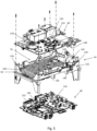
- the electronic subassembly 38 comprises a metal heat dissipation device 44 on which are fixed a first printed circuit board 46 and a second printed circuit board 48.
- the first circuit board 46 is attached to the top of the heat sink device 44.
- the second circuit board 48 is attached to the bottom of the heat sink device 44.
- the heat dissipation device 44 comprises a metal plate 50 supported by 4 vertical pillars 52, 54, 56, 58 oriented towards the bottom of the case 22 and of which each free end 60, 62, 64, 66 is provided with a pitch of screw.
- the metal plate 50 is arranged between the two printed circuit boards 46, 48.
- the housing 12 and the electronic subassembly 38 are fixed together by screwing.
- the lower facade 22 of the casing comprises, at each of its corners, holes through which the first fixing screws 68 are inserted into the screw threads of the four pillars 52, 54, 56, 58 thus ensuring the maintaining the electronic sub-assembly 38 in the housing 12.
- Other fixing screws fix the other facades to the electronic sub-assembly 38.
- second fixing screws 70 in particular on the front facade 20, fix the first metal part 40 of the casing to the metal connector bodies of the printed circuit boards 46, 48.
- third fixing screws 72 fix the first metal part 40 of the casing to the second metal part 42 of the casing.
- This assembly by bringing the metal parts of the electronic sub-assembly 38 into contact with the metal casing 12, not only makes it possible to achieve a first level of heat dissipation, and also to achieve a first level of protection of the electronic sub-assembly against electromagnetic interference.
- the heat dissipation device 44 may comprise three or more pillars, the objective being to maintain the plate 50 raised with regard to the bottom of the case 22, thus allowing the fixing of the second printed circuit board 48.
- the fan support 84 is arranged in continuity with the left vertical wall 82.
- the fan support 84 extends from the end of the left vertical wall 82 to the rear vertical wall 78.
- the fan support 84 is arranged in a vertical plane perpendicular to the longitudinal axis L.
- Fan support 84 is generally rectangular in shape.
- the support has two transverse edges 86, 88 and two vertical edges 90, 92.
- the two vertical edges 90, 92 are, one directly in contact with the end of the left vertical wall 82 and the other directly in contact with the wall rear vertical 78.
- the two transverse edges 86, 88 are respectively arranged one at a vertical height above the plate 50, the other at a vertical height below the plate 50.
- the two edges 86, 88 transverse are arranged at equal distance above and below the plate 50.
- the fan support 84 has in its center a circular opening of diameter almost identical to the diameter of the impeller of a fan 36, allowing a fan 36 arranged in the support 84 to ventilate both the upper face of the plate 74 and the lower face of the plate 76.
- the upper face of the plate 74 comprises a first horizontal planar section 94 of rectangular shape.
- the first section 94 is delimited by two longitudinal edges parallel to the rear and front sides of the plate.
- the two longitudinal borders each respectively form a longitudinal rear vertical wall 96 and a longitudinal front vertical wall 98.
- the first section 94 is centered symmetrically along the longitudinal axis of symmetry L of the plateau.
- the first section 94 extends longitudinally from the transverse right side of the tray 50 to approximately 4/5 of the length of the tray along the longitudinal axis.
- the first section 94 also extends transversely, symmetrically on either side of the longitudinal axis of symmetry L of the plate 50 up to a total width along the transverse axis T representing 3/5 of the width of the plate .
- the first section 94 forms a rectangular recess in the top face of the tray, also forming a rectangular protuberance 100 on the underside of the tray 76.
- the first section 94 comprises a plurality of vertical cooling fins 102 directed upwards and each extending along the longitudinal axis L over the entire length of the first section 94.
- the fins 102 are regularly spaced from each other by spaces between fins 104.
- the plurality of fins 102 is therefore arranged between the longitudinal rear vertical wall 96 and the longitudinal front vertical wall 98 of the first section 94.
- Each fin is parallel to the longitudinal walls of the first section 94.
- the walls vertical 96, 98 longitudinal are similar to cooling fins.
- the rear vertical wall 96 and the front vertical wall 98 of the first section 94 are connected to the fan support 84 by two additional walls 106, 108.
- the two additional walls 106, 108 respectively connect the two vertical walls 96, 98 to the two edges vertical 90, 92 of the fan support 84.
- the upper face of the plate 74 comprises, apart from the first section 94 and on each side of the two walls 96, 98 of the first section 94, respectively a second section 112 and a third section 114.
- the second section 112 and third section 114 are generally flat rectangular surfaces.
- the second section 112 is the section directly adjacent to the longitudinal rear vertical wall 96 of the first section 94.
- the third section 114 is the section directly adjacent to the longitudinal front vertical wall 98.
- the second section 112 and the third section 114 extend longitudinally on either side of the first section 94, from the right lateral side of the plate 50 to the left lateral side of the plate 50.
- the second section 112 and the third section 114 also extend transversely respectively from each longitudinal vertical wall of the first section 96, 98 to the rear vertical wall 78 and to the front vertical wall 80 of the plate 50.
- the second 112 and the third section 114 are slightly raised vertically relative to the first section 94.
- the first printed circuit board 46 and the second printed circuit board 48 comprise both on their top face and on their bottom face electronic components 116, 118, 120, 122 interconnected by conductive tracks.
- Certain components or certain conductive tracks, in particular high current conductive tracks, can form heat-generating zones 124, 126, 128, 130, 132, that is to say zones generating heat during operation of the module of the multimedia control unit 10.
- the upper face of the plate 74 is adapted to receive the first printed circuit board 46.
- the upper face of the plate 74 is equipped with several fixing studs 134, 135 for the first printed circuit board 46.
- the fixing studs 134, 135 provided for the first printed circuit board 46 are oriented vertically upwards and allow the flat maintenance, in a horizontal plane, of the first printed circuit board 46. All the fixing studs 134, 135 are of hollow cylindrical shape, the hollow being a thread.
- the first printed circuit board 46 is therefore provided to bear by screwing against the plurality of fins 102 of the first section 94.
- the fixing studs 134 are distributed over the upper face 74 of the plate 50.
- a first fixing stud 134 is arranged at the end of the second section, in direct proximity to the fan support and in direct proximity to a first corner of the tray.
- a second 134, a third 134 and a fourth mounting pad 134 are generally arranged vertically aligned with the three vertical mounting pillars of the heat dissipation device 44 disposed at the other three corners of the plate.
- a fifth fixing stud 135 is arranged vertically in the fin arranged along the longitudinal axis of symmetry of the plate. The fifth stud is generally arranged at 2/3 of the length of said fin.
- a sixth fixing stud 135 is arranged adjacent to the rear wall of the first section, on the second section 112, globally at 1/3 of the length of the first section.
- fixing pads 134 are generally provided to hold the first printed circuit board 46 at these four angles.
- Two other fixing studs 135 are arranged on the cooling fins 102, close to the heat-generating zones 124, 126, 128 of the first printed circuit board 46 so as to improve the support of these heat-generating zones 124, 126, 128 on the cooling fins 102.
- the upper face of the first section 94 comprises solid studs 136, the upper free end of which serves as a bearing surface for the heat-generating zones 124, 126 or hot spots of the first power circuit board 46 in operation.
- Each solid stud 136 is of solid cylindrical shape arranged in the plurality of cooling fins 102.
- the solid studs 136 are overmolded with the plurality of cooling fins 102.
- a flat cooling zone 138 is arranged transversely on four fins.
- the flat cooling zone 138 also allows a heat generating zone 128 ( figure 7 ) of the first printed circuit board 46, to come to rest on the heat dissipation device 44.
- the inter-fin spaces 104 under the flat cooling zone 138 allow the passage of an air flow promoting the heat dissipation of the heat-generating zone 128 bearing on the flat cooling zone 138.
- the intermediate part 146 comprises two circular holes allowing the clipping of the electrical connection element 140 in two fixing lugs of the second section 112.
- the fixing lugs hold the intermediate part 146 in contact with the upper face of the second section 112
- the intermediate part 146 is extended on one side by the first flexible end 142, and on the other side by the second flexible end 144.
- the two lugs are arranged on the upper surface of the free end of a cylindrical metal support with a generally rectangular base.
- the support is of the same vertical height as the rear vertical wall 78.
- the intermediate part 146 comes into direct contact with the surface of the free end of the metal support.
- the electrical connection element 140 is arranged in the lugs so that the first end 142 extends transversely towards the inside of the heat dissipation device 44 and vertically upward and in that the second end 144 extends transversely outside the heat dissipation device 44.
- the intermediate part 146 can be fixed by welding on the plate 50; in this case, the plate 50 has no lugs and the intermediate part has no holes.
- each flexible end comprises three curved blades so as to form at the free end of the three blades a bearing surface.
- the three blades of the second end 144 of the electrical connection element 140 are designed to be compressed in contact between the heat dissipation device 44 and the casing of the control unit. More specifically, each curved end of the three curved blades of the second end 144 is provided to come into contact bearing on the rear face of the case 18.
- the three blades of the first end 142 of the electrical connection element 140 are intended to be compressed between the heat dissipation device 44 and a connector of the first printed circuit board 46. More precisely, each curved end of the three blades curves of the first end 142 is provided to come into contact bearing on the metal body 148 of a connector of the connector type dedicated to high-speed communications or also of an antenna connector or radio frequency antenna cable.
- the electrical connection element 140 allows the contacting, by crushing of its ends, of a connector with a metal body 148 of the first printed circuit board 46 to the heat dissipation device 44 as well as to the housing 12 of the multimedia control unit 10. It may be, preferably, a connector dedicated to high-speed communications or also an antenna connector or radiofrequency antenna cable.
- the contacting by the electrical connection element 140 of a connector with the heat dissipation device 44 and the casing allows local electrical grounding of said connector.
- the multimedia control unit 10 is intended to be fixed to the body of the vehicle, the body of the vehicle serving as electrical ground.
- the heat dissipation device 44 has in this case a protective role against electromagnetic interference which can disturb the signals transiting in said connector and also to limit the electromagnetic radiation of said connector during the transit of high-speed signals or during the transmission of radio frequency signals.
- the rear vertical wall 78 and the front vertical wall 80 of the plate 50 each comprise a circular opening 150, 152.
- Each circular opening 150, 152 is arranged at the level of the upper surface of the second section 112 and of the third section 114.
- a By way of example and without limitation, each circular opening 150, 152 is arranged at the left end of the rear vertical wall 78 and front 80.
- These openings 150, 152 are provided to evacuate water which would have formed by condensation on the second and third section. The water evacuated by these circular openings 150, 152 is lodged in the bottom of the case, that is to say in the lower facade 22.
- the lower facade 22 is equipped at each of its four opening angles allowing water to drain out of the housing.
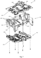
- the heat dissipation device 44 is presented turned over so as to visualize the lower face 76 of the plate 50.
- the lower face of the first section 94, of the second section 112 and of the third section 114 can be seen there.
- the underside of the first section 94 is slightly raised relative to the flat surfaces of the second and third sections.
- the lower surface of the first section 94 forms the rectangular protrusion 100 on the underside of the tray 76.
- the lower face of the second 112 and of the third 114 section are generally aligned along the same horizontal plane.
- fixing studs 154 are generally provided to hold the second printed circuit board 48 close to these four corners.
- Another fixing pad 155 of the second printed circuit board 48 is arranged on the protruding lower face of the first section 94, so as to improve the support of the heat-generating zones 130, 132 ( figure 5 ) of the second printed circuit board 48 on the first section 94.
- the underside of the first section 94 includes flat generally rectangular cooling surfaces 156 and slightly raised with respect to the surface of the first section 94 so as to form protuberances on the face. bottom of the first section 94. These flat cooling surfaces 156 allow heat generating areas 130, 132 of the second printed circuit board 48 to bear against the heat dissipation device 44.
- the heat-generating zones 130, 132 are located on the top face of the second printed circuit board 48 and are directly in contact by pressing on the flat cooling surfaces 156. Nevertheless, it is also possible to cool heat-generating areas of the underside of the second printed circuit board 48 when these bear indirectly on the flat cooling surfaces 156; that is to say separated from the flat cooling surfaces 156 by the thickness of the printed circuit board.
- the underside of the plate 76 comprises six electrical connection elements 140 allowing the contacting, by crushing of their flexible end, of a connector with a metal body 148 of the second printed circuit board 48 to the heat dissipation device 44 as well as than to the box 12 of the multimedia control unit 10.
- These six electrical connection elements 140 are identical and have the same function as that described and mounted on the upper face of the plate 74.
- connection elements 140 can also be used to bring a conductive element of the first printed circuit board 46 or of the second printed circuit board 48 into contact with the plate 50 and with the housing 12 so to protect the conductive element against thermal heating and against electromagnetic interference.
- An electrical ground copper track can be a conductive element of printed circuit boards, as well as metal bodies of components 148.
- a method of assembling the multimedia control module 10 may comprise several steps.
- a first step consists in having two printed circuit boards 46, 48 comprising heat-generating zones 124, 126, 128, 130, 132.
- a second step consists in having a heat dissipation device 44 as described previously through the figure 4 And 6 .
- a third step consists in having a box 12 comprising a box bottom 22 and a front face 20.
- a fourth step consists in fixing the first printed circuit board 46 on the upper face of the plate 74 in order to put the heat generators 124, 126, 128 of the first printed circuit board 46 on the upper face of the plate 74.
- a fifth step consists in fixing the second printed circuit board 48 on the lower face of the plate 76 in order to bring the heat-generating areas 130, 132 of the second printed circuit board 48 on the underside of the plate 76.
- a sixth step consists in fixing the fixing pillars 52, 54, 56, 58 of the heat dissipation device 44 equipped with the two printed circuit boards 46, 48 on the bottom of the case 22.
- An additional step can consist of arranging electrical connection elements 140 comprising flexible ends 142, 144 on the plate 50 so as to bring into contact, by compression of the flexible ends, conductive elements 148 of the printed circuit boards 46, 48 with the plate 50 and with the housing 12.
- Another step may consist in fixing the assembly of the plate 50 with the printed circuit boards 46, 48 on one of the facades of the casing 14, 16, 18, 20.
- Another step may consist in providing a casing 12, two facades of which comprise openings 32, 34 allowing the circulation of a flow of air in the multimedia control unit 10.
- One step may consist in assembling a fan 36 opposite a facade 16 comprising the openings 34 in order to facilitate the circulation of an air flow in the unit media control 10.
Landscapes
- Engineering & Computer Science (AREA)
- Physics & Mathematics (AREA)
- Thermal Sciences (AREA)
- Microelectronics & Electronic Packaging (AREA)
- Mechanical Engineering (AREA)
- General Engineering & Computer Science (AREA)
- Cooling Or The Like Of Electrical Apparatus (AREA)
Claims (17)
- Wärmeableitungsvorrichtung (44), umfassendeine allgemein rechteckige metallische Kühlplatte (50);wobei die Metallplatte (50) auf ihrer oberen Fläche (74) erste Befestigungsmittel (134, 135) einer ersten gedruckten Leiterplatte (46) umfasst, die vorgesehen sind, um mindestens eine wärmeerzeugende Zone (124) der ersten gedruckten Leiterplatte (46) auf der oberen Fläche (74) der Platte (50) in Abstützung zu bringen;wobei die Metallplatte (50) auf ihrer unteren Fläche (76) zweite Befestigungsmittel (154, 155) einer zweiten gedruckten Leiterplatte (48) umfasst, die vorgesehen sind, um mindestens eine wärmeerzeugende Zone (130) der zweiten gedruckten Leiterplatte (48) auf der unteren Fläche (76) der Platte (50) in Abstützung zu bringen;wobei die obere Fläche (74) der Platte (50) einen ersten Abschnitt (94) umfasst, der mit einer Vielzahl vertikaler Kühlflügel (102) ausgestattet ist, die sich jeweils in einer Längsrichtung etwa parallel zu einer Seite der Platte (50) erstrecken;dadurch gekennzeichnet, dassder erste Abschnitt (94) einen Teil der ersten Befestigungsmittel (135) umfasst, so dass die Abstützung einer wärmeerzeugenden Zone (124) der ersten gedruckten Leiterplatte (46) auf den Kühlflügeln (102) gestattet ist, und dassdie untere Fläche des ersten Abschnitts (94) mindestens eine ebene Kühloberfläche (156) umfasst, die einen Vorsprung auf der unteren Fläche bildet, so dass die Abstützung einer wärmeerzeugenden Zone (130) der zweiten gedruckten Leiterplatte (48) auf der ebenen Kühloberfläche (156) gestattet ist.
- Wärmeableitungsvorrichtung (44) nach Anspruch 1, dadurch gekennzeichnet, dass der erste Abschnitt (94) eine ebene Kühlzone (138) umfasst, die sich quer auf der Höhe von mindestens zwei Flügeln (102) erstreckt, so dass die Abstützung einer wärmeerzeugenden Zone (124) der ersten gedruckten Leiterplatte (46) auf der ebenen Kühlzone (138) gestattet ist.
- Wärmeableitungsvorrichtung (44) nach einem der vorangehenden Ansprüche, dadurch gekennzeichnet, dass der erste Abschnitt (94) mindestens einen überformten vertikalen vollen zylindrischen Stift (136) in einem Kühlflügel (102) umfasst, so dass die Abstützung einer wärmeerzeugenden Zone (124) der ersten gedruckten Leiterplatte (46) auf dem freien Ende des vollen zylindrischen Stifts (136) gestattet ist.
- Wärmeableitungsvorrichtung (44) nach einem der vorangehenden Ansprüche, dadurch gekennzeichnet, dass der erste Abschnitt (94) eine rechteckige Vertiefung in der oberen Fläche (74) der Platte (50) bildet, die einen rechteckigen Vorsprung (100) auf der unteren Fläche (76) der Platte (50) bildet.
- Wärmeableitungsvorrichtung (44) nach einem der vorangehenden Ansprüche, dadurch gekennzeichnet, dass die untere Fläche des ersten Abschnitts (96) einen Teil der zweiten Befestigungsmittel (155) umfasst, so dass die Abstützung mindestens einer wärmeerzeugenden Zone (130) der zweiten gedruckten Leiterplatte (48) auf der unteren Fläche des ersten Abschnitts (94) gestattet ist.
- Wärmeableitungsvorrichtung (44) nach einem der vorangehenden Ansprüche, dadurch gekennzeichnet, dassdie Platte (50) mindestens drei Metallpfeiler (52, 54, 56) aufweist, die sich vertikal nach unten ab der unteren Fläche (76) der Platte (50) erstrecken;das untere Ende jedes Pfeilers (52, 54, 56) mit einem Befestigungsmittel (60, 62, 64, 66) versehen ist, das vorgesehen ist, um auf einem Gehäuseboden (22) befestigt zu sein, so dass die Platte (50) erhöht gehalten wird, um die zweite gedruckte Leiterplatte (48) auf der unteren Fläche (76) der Platte (50) anzuordnen.
- Wärmeableitungsvorrichtung (44) nach einem der vorangehenden Ansprüche, dadurch gekennzeichnet, dass eine transversale Seite der Platte (50) einen Ventilatorhalter (84) aufweist, der imstande ist, einen Ventilator (36) aufzunehmen, der erlaubt, einen Kühlluftstrom der Platte (50) gemäß einer Längsrichtung zu erzeugen.
- Wärmeableitungsvorrichtung (44) nach Anspruch 7, dadurch gekennzeichnet, dass die Platte (50) Ablenker (106, 108) aufweist, die zwischen dem Ventilatorhalter (84) und dem ersten Abschnitt (94) eingerichtet sind, die imstande sind, den Kühlluftstrom zu lenken.
- Wärmeableitungsvorrichtung (44) nach Anspruch 7 oder 8, dadurch gekennzeichnet, dass
die Platte (50) eine Öffnung (110) zwischen dem ersten Abschnitt (94) und dem Ventilatorhalter (84) aufweist, so dass ein Luftstrom auf den zwei Flächen (74, 76) der Platte (50) begünstigt wird. - Wärmeableitungsvorrichtung (44) nach einem der vorangehenden Ansprüche, dadurch gekennzeichnet, dassdie Platte (50) ein elektrisches Verbindungselement (140) umfasst, das zwei flexible Kontaktenden (142, 144) umfasst;wobei das erste Ende (142) vorgesehen ist, um einen elektrischen Kontakt durch Kompression zwischen der Kühlplatte (50) und einem elektrisch leitenden Element (148) der ersten gedruckten Leiterplatte (46) oder der zweiten gedruckten Leiterplatte (48) herzustellen;wobei das zweite Ende (144) vorgesehen ist, um einen elektrischen Kontakt durch Kompression zwischen der Platte (50) und einem Metallkasten (12) herzustellen, der die Wärmeableitungsvorrichtung (44) einschließt;so dass das elektrisch leitende Element (148) thermisch und elektromagnetisch geschützt wird.
- Wärmeableitungsvorrichtung (44) nach Anspruch 10, dadurch gekennzeichnet, dass das elektrische Verbindungselement (140) einen Übergangsteil (146) umfasst, mit dem das Verbindungselement (140) auf der Platte (50) befestigt ist, wobei der Übergangsteil (146) auf der einen Seite vom ersten flexiblen Ende (142) in hauptsächlich einer zur Platte (50) senkrechten Richtung und auf der anderen Seite vom zweiten flexiblen Ende (144) in hauptsächlich einer zur Platte (50) koplanaren Richtung verlängert wird.
- Wärmeableitungsvorrichtung (44) nach einem der Ansprüche 1 bis 9, dadurch gekennzeichnet, dass die Wärmeableitungsvorrichtung (44) aus einem einzigen Metallteil besteht.
- Elektronische Montage, die eine Wärmeableitungsvorrichtung (44) nach einem der vorangehenden Ansprüche aufweist; wobei die elektronische Montage umfasst:eine erste gedruckte Leiterplatte (46), die eine wärmeerzeugende Zone (124) in Abstützung auf der oberen Fläche (74) der Kühlplatte (50) aufweist;eine zweite gedruckte Leiterplatte (48), die eine wärmeerzeugende Zone (130) in Abstützung auf der unteren Fläche (76) der Kühlplatte (50) aufweist.
- Elektronische Montage nach Anspruch 13 und Anspruch 6, dadurch gekennzeichnet, dass sie einen global rechteckigen parallelepipedischen geschlossenen Metallkasten (12) aufweist;
wobei die Wärmeableitungsvorrichtung (44) im Boden des Kastens (22) befestigt ist. - Elektronische Montage nach Anspruch 14, dadurch gekennzeichnet, dass der Kasten (12) umfassteine erste Gruppe von Öffnungen (32), die auf einer ersten Seitenfläche (14) des Kastens (12) und gegenüber der Kühlplatte (50) eingerichtet ist;eine zweite Gruppe von Öffnungen (34), die auf einer zweiten Seitenfläche (16) des Kastens (12) entgegengesetzt zur ersten Fläche (14) und gegenüber der Kühlplatte (50) eingerichtet ist;so dass die Zirkulation eines Kühlluftstroms ab der ersten Gruppe von Öffnungen (32) bis zur zweiten Gruppe von Öffnungen (34) gestattet ist.
- Elektronische Montage nach Anspruch 15 und Anspruch 7, dadurch gekennzeichnet, dass ein Ventilator (36) im Ventilatorhalter (84) angebracht und im Kasten (12) gegenüber von einer der zwei Gruppen von Öffnungen (32, 34) eingerichtet ist, so dass die Zirkulation eines Kühlluftstroms erleichtert wird.
- Elektronische Montage nach einem der Ansprüche 14 bis 16 und einem der Ansprüche 10 bis 11, dadurch gekennzeichnet, dassdie Platte (50) ein elektrisches Verbindungselement (140) aufweist;mindestens eine der gedruckten Leiterplatten (46, 48) ein leitendes Element (148) umfasst;wobei das leitende Element (148) durch das elektrische Verbindungselement (140) in elektrischem Kontakt mit der Platte (50) und dem Metallkasten (12) ist, so dass das leitende Element (148) thermisch und elektromagnetisch geschützt wird.
Applications Claiming Priority (2)
| Application Number | Priority Date | Filing Date | Title |
|---|---|---|---|
| FR1662311A FR3060202B1 (fr) | 2016-12-12 | 2016-12-12 | Dispositif de dissipation de chaleur d'une unite de controle multimedia |
| PCT/EP2017/081882 WO2018108702A2 (fr) | 2016-12-12 | 2017-12-07 | Dispositif de dissipation de chaleur d'une unite de controle multimedia |
Publications (2)
| Publication Number | Publication Date |
|---|---|
| EP3551501A2 EP3551501A2 (de) | 2019-10-16 |
| EP3551501B1 true EP3551501B1 (de) | 2023-04-05 |
Family
ID=59031000
Family Applications (1)
| Application Number | Title | Priority Date | Filing Date |
|---|---|---|---|
| EP17825140.1A Active EP3551501B1 (de) | 2016-12-12 | 2017-12-07 | Wärmeableitungsvorrichtung für eine multimedia-steuereinheit |
Country Status (5)
| Country | Link |
|---|---|
| US (1) | US10842045B2 (de) |
| EP (1) | EP3551501B1 (de) |
| CN (1) | CN110062719B (de) |
| FR (1) | FR3060202B1 (de) |
| WO (1) | WO2018108702A2 (de) |
Families Citing this family (10)
| Publication number | Priority date | Publication date | Assignee | Title |
|---|---|---|---|---|
| JP7081203B2 (ja) * | 2018-02-26 | 2022-06-07 | トヨタ自動車株式会社 | 放熱フィン構造及びこれを用いた電子基板の冷却構造 |
| US11165132B2 (en) * | 2019-01-01 | 2021-11-02 | Airgain, Inc. | Antenna assembly for a vehicle |
| KR102722279B1 (ko) * | 2019-06-28 | 2024-10-25 | 엘지전자 주식회사 | Avn 장치 |
| JP7164618B2 (ja) * | 2019-07-12 | 2022-11-01 | 華為技術有限公司 | インテリジェント車両における車載コンピュータ装置及びインテリジェント車両 |
| CN211630547U (zh) * | 2020-04-22 | 2020-10-02 | 苏州车邦智能科技有限公司 | 汽车ecu控制器 |
| JP7549469B2 (ja) * | 2020-06-17 | 2024-09-11 | 日立Astemo株式会社 | 電子制御装置 |
| CN113977643B (zh) * | 2021-10-28 | 2023-05-02 | 深圳市键键通科技有限公司 | 一种弧面车窗贴膜切割系统 |
| TWM642121U (zh) * | 2023-03-10 | 2023-06-01 | 酷碼科技股份有限公司 | 電源供應器 |
| DE102024108242A1 (de) * | 2023-03-31 | 2024-10-02 | Eaton Intelligent Power Limited | Steuereinheit mit kühlung |
| WO2025099751A1 (en) * | 2023-11-07 | 2025-05-15 | Tvs Motor Company Limited | A vehicle |
Citations (1)
| Publication number | Priority date | Publication date | Assignee | Title |
|---|---|---|---|---|
| US20060139878A1 (en) * | 2004-12-29 | 2006-06-29 | Widmayer Robert B | Heat sink and component support assembly |
Family Cites Families (28)
| Publication number | Priority date | Publication date | Assignee | Title |
|---|---|---|---|---|
| US5343359A (en) * | 1992-11-19 | 1994-08-30 | Cray Research, Inc. | Apparatus for cooling daughter boards |
| US5689403A (en) * | 1994-12-27 | 1997-11-18 | Motorola, Inc. | Intercooled electronic device |
| US5621614A (en) * | 1995-08-24 | 1997-04-15 | Lucasey Manufacturing Company | Apparatus for mounting and enclosing an appliance |
| US6305463B1 (en) * | 1996-02-22 | 2001-10-23 | Silicon Graphics, Inc. | Air or liquid cooled computer module cold plate |
| US5986887A (en) * | 1998-10-28 | 1999-11-16 | Unisys Corporation | Stacked circuit board assembly adapted for heat dissipation |
| US6151215A (en) * | 1998-12-08 | 2000-11-21 | Alliedsignal Inc. | Single mount and cooling for two two-sided printed circuit boards |
| JP3852253B2 (ja) * | 1999-10-21 | 2006-11-29 | 富士通株式会社 | 電子部品の冷却装置及び電子機器 |
| US6707675B1 (en) * | 2002-12-18 | 2004-03-16 | Hewlett-Packard Development Company, L.P. | EMI containment device and method |
| TW571613B (en) * | 2003-04-29 | 2004-01-11 | Quanta Comp Inc | Functional module built-in with heat dissipation fin |
| TW573458B (en) * | 2003-06-09 | 2004-01-21 | Quanta Comp Inc | Functional module having built-in heat dissipation fins |
| KR20050008258A (ko) * | 2003-07-15 | 2005-01-21 | 엘지이노텍 주식회사 | 튜너 |
| US7111674B2 (en) * | 2003-08-06 | 2006-09-26 | Fujitsu Limited | Heat dissipating housing with interlocking chamfers and ESD resistance |
| US7061126B2 (en) * | 2003-10-07 | 2006-06-13 | Hewlett-Packard Development Company, L.P. | Circuit board assembly |
| US20050134526A1 (en) * | 2003-12-23 | 2005-06-23 | Patrick Willem | Configurable tiled emissive display |
| JP4420230B2 (ja) * | 2005-05-24 | 2010-02-24 | 株式会社ケンウッド | 電子機器の空冷装置 |
| US7298622B2 (en) * | 2005-06-15 | 2007-11-20 | Tyco Electronics Corporation | Modular heat sink assembly |
| TWI326578B (en) * | 2005-10-20 | 2010-06-21 | Asustek Comp Inc | Pcb with heat sink by through holes |
| CN201274630Y (zh) * | 2008-10-13 | 2009-07-15 | 芯发威达电子(上海)有限公司 | 散热装置 |
| US7773378B2 (en) * | 2008-10-21 | 2010-08-10 | Moxa, Inc. | Heat-dissipating structure for expansion board architecture |
| EP2292472A1 (de) * | 2009-09-04 | 2011-03-09 | Delphi Technologies, Inc. | Geschlossenes und internes Kühlsystem für ein Autoradio |
| JP5668506B2 (ja) * | 2011-02-03 | 2015-02-12 | 三菱マテリアル株式会社 | パワーモジュール用基板の製造方法及びパワーモジュール用基板 |
| TWI426214B (zh) * | 2011-03-15 | 2014-02-11 | Sunonwealth Electr Mach Ind Co | 燈具 |
| US8971041B2 (en) * | 2012-03-29 | 2015-03-03 | Lear Corporation | Coldplate for use with an inverter in an electric vehicle (EV) or a hybrid-electric vehicle (HEV) |
| JP5725050B2 (ja) * | 2013-01-29 | 2015-05-27 | トヨタ自動車株式会社 | 半導体モジュール |
| CN104470321B (zh) * | 2013-09-25 | 2017-11-17 | 泰科电子(上海)有限公司 | 用于插头的连接器和连接器组合 |
| CN105684565B (zh) * | 2014-09-16 | 2017-08-29 | 深圳市大疆创新科技有限公司 | 散热装置及采用该散热装置的uav |
| CN105699946B (zh) * | 2016-03-23 | 2017-10-20 | 西安电子工程研究所 | 一种具有多个中空锥形散热风道的多层密封机箱 |
| TWI686549B (zh) * | 2018-11-23 | 2020-03-01 | 緯穎科技服務股份有限公司 | 應用於散熱鰭片之可調式固定裝置及其電子設備 |
-
2016
- 2016-12-12 FR FR1662311A patent/FR3060202B1/fr active Active
-
2017
- 2017-12-07 WO PCT/EP2017/081882 patent/WO2018108702A2/fr not_active Ceased
- 2017-12-07 CN CN201780076413.XA patent/CN110062719B/zh active Active
- 2017-12-07 EP EP17825140.1A patent/EP3551501B1/de active Active
- 2017-12-07 US US16/466,471 patent/US10842045B2/en active Active
Patent Citations (1)
| Publication number | Priority date | Publication date | Assignee | Title |
|---|---|---|---|---|
| US20060139878A1 (en) * | 2004-12-29 | 2006-06-29 | Widmayer Robert B | Heat sink and component support assembly |
Also Published As
| Publication number | Publication date |
|---|---|
| WO2018108702A3 (fr) | 2018-08-23 |
| US10842045B2 (en) | 2020-11-17 |
| CN110062719B (zh) | 2022-05-31 |
| US20190335621A1 (en) | 2019-10-31 |
| FR3060202B1 (fr) | 2019-07-05 |
| WO2018108702A2 (fr) | 2018-06-21 |
| EP3551501A2 (de) | 2019-10-16 |
| FR3060202A1 (fr) | 2018-06-15 |
| CN110062719A (zh) | 2019-07-26 |
Similar Documents
| Publication | Publication Date | Title |
|---|---|---|
| EP3551501B1 (de) | Wärmeableitungsvorrichtung für eine multimedia-steuereinheit | |
| EP3712743B1 (de) | Dissipatives verbindungsmodul für erweiterungskarte mit m.2 formfaktor | |
| FR2569309A1 (fr) | Connecteur pour plaque de base | |
| FR3003407A1 (fr) | Enveloppe electrique a agencement mecanique ameliore | |
| EP3383153A1 (de) | Vorrichtung zur wärmeableitung einer elektronischen vorrichtung | |
| EP1504636B1 (de) | Gekühlter leistungsschalter | |
| FR2577102A1 (fr) | Structure de montage pour modules de circuits electroniques | |
| CA2748005C (fr) | Pack electrique a modules de commande et de puissance separes | |
| FR2845821A1 (fr) | Substrat electronique d'un module electronique a trois dimensions a fort pouvoir de dissipation thermique et module electronique | |
| FR2477828A1 (fr) | Systeme d'interconnexion electrique et thermique pour des cartes a circuits electroniques, et armoire electrique equipee d'un tel systeme | |
| EP0233674A1 (de) | Informationsbus-Verbinder | |
| EP0187580A1 (de) | Gehäuse für ein mit einem Wasserumlauf gekühltes Hochfrequenzleistungselement | |
| EP3206469B1 (de) | Halterungsvorrichtung für mindestens zwei leiterplatten, entsprechendes elektronisches modul und entsprechendes elektronisches system | |
| EP4345577A1 (de) | Kühlkörper für eine berechnungsblatt-array-karte | |
| EP2362720B1 (de) | Elektronisches module und elektronische Anordnung umfassend dieses Modul | |
| EP1346448A1 (de) | Ventilationssystem für ein elektrisches gehäuse | |
| FR2764473A1 (fr) | Tiroir electronique comportant un dispositif ameliore d'evacuation de chaleur | |
| EP1346447B1 (de) | Integriertes verdrahtungssystem für ein elektrisches gehäuse | |
| EP1950641B1 (de) | Elektrisches Versorgungsmodul für einem Chassis von Elektronikkarten | |
| EP4324311A1 (de) | Modulare elektronische vorrichtung mit optimierter kühlung | |
| EP4034396B1 (de) | Gehäuse einer elektronischen schnittstelle zur steuerung einer elektrischen heizvorrichtung | |
| EP0091335B1 (de) | Thermisches Verbindungssystem | |
| FR2956558A1 (fr) | Module electronique a dissipation thermique amelioree | |
| FR3149143A1 (fr) | Véhicule comportant un boîtier d’antenne à dissipation thermique améliorée. | |
| FR3150393A1 (fr) | Boîtier d’appareil électronique comportant un radiateur et un ventilateur |
Legal Events
| Date | Code | Title | Description |
|---|---|---|---|
| STAA | Information on the status of an ep patent application or granted ep patent |
Free format text: STATUS: UNKNOWN |
|
| STAA | Information on the status of an ep patent application or granted ep patent |
Free format text: STATUS: THE INTERNATIONAL PUBLICATION HAS BEEN MADE |
|
| PUAI | Public reference made under article 153(3) epc to a published international application that has entered the european phase |
Free format text: ORIGINAL CODE: 0009012 |
|
| STAA | Information on the status of an ep patent application or granted ep patent |
Free format text: STATUS: REQUEST FOR EXAMINATION WAS MADE |
|
| 17P | Request for examination filed |
Effective date: 20190703 |
|
| AK | Designated contracting states |
Kind code of ref document: A2 Designated state(s): AL AT BE BG CH CY CZ DE DK EE ES FI FR GB GR HR HU IE IS IT LI LT LU LV MC MK MT NL NO PL PT RO RS SE SI SK SM TR |
|
| AX | Request for extension of the european patent |
Extension state: BA ME |
|
| DAV | Request for validation of the european patent (deleted) | ||
| DAX | Request for extension of the european patent (deleted) | ||
| STAA | Information on the status of an ep patent application or granted ep patent |
Free format text: STATUS: EXAMINATION IS IN PROGRESS |
|
| 17Q | First examination report despatched |
Effective date: 20220407 |
|
| GRAP | Despatch of communication of intention to grant a patent |
Free format text: ORIGINAL CODE: EPIDOSNIGR1 |
|
| STAA | Information on the status of an ep patent application or granted ep patent |
Free format text: STATUS: GRANT OF PATENT IS INTENDED |
|
| INTG | Intention to grant announced |
Effective date: 20220923 |
|
| GRAJ | Information related to disapproval of communication of intention to grant by the applicant or resumption of examination proceedings by the epo deleted |
Free format text: ORIGINAL CODE: EPIDOSDIGR1 |
|
| STAA | Information on the status of an ep patent application or granted ep patent |
Free format text: STATUS: EXAMINATION IS IN PROGRESS |
|
| GRAP | Despatch of communication of intention to grant a patent |
Free format text: ORIGINAL CODE: EPIDOSNIGR1 |
|
| STAA | Information on the status of an ep patent application or granted ep patent |
Free format text: STATUS: GRANT OF PATENT IS INTENDED |
|
| INTC | Intention to grant announced (deleted) | ||
| INTG | Intention to grant announced |
Effective date: 20221219 |
|
| GRAS | Grant fee paid |
Free format text: ORIGINAL CODE: EPIDOSNIGR3 |
|
| GRAA | (expected) grant |
Free format text: ORIGINAL CODE: 0009210 |
|
| STAA | Information on the status of an ep patent application or granted ep patent |
Free format text: STATUS: THE PATENT HAS BEEN GRANTED |
|
| RAP3 | Party data changed (applicant data changed or rights of an application transferred) |
Owner name: APTIV TECHNOLOGIES LIMITED |
|
| AK | Designated contracting states |
Kind code of ref document: B1 Designated state(s): AL AT BE BG CH CY CZ DE DK EE ES FI FR GB GR HR HU IE IS IT LI LT LU LV MC MK MT NL NO PL PT RO RS SE SI SK SM TR |
|
| REG | Reference to a national code |
Ref country code: GB Ref legal event code: FG4D Free format text: NOT ENGLISH |
|
| REG | Reference to a national code |
Ref country code: DE Ref legal event code: R096 Ref document number: 602017067511 Country of ref document: DE |
|
| REG | Reference to a national code |
Ref country code: CH Ref legal event code: EP |
|
| REG | Reference to a national code |
Ref country code: AT Ref legal event code: REF Ref document number: 1558006 Country of ref document: AT Kind code of ref document: T Effective date: 20230415 |
|
| REG | Reference to a national code |
Ref country code: IE Ref legal event code: FG4D Free format text: LANGUAGE OF EP DOCUMENT: FRENCH |
|
| P01 | Opt-out of the competence of the unified patent court (upc) registered |
Effective date: 20230424 |
|
| REG | Reference to a national code |
Ref country code: LT Ref legal event code: MG9D |
|
| REG | Reference to a national code |
Ref country code: NL Ref legal event code: MP Effective date: 20230405 |
|
| REG | Reference to a national code |
Ref country code: AT Ref legal event code: MK05 Ref document number: 1558006 Country of ref document: AT Kind code of ref document: T Effective date: 20230405 |
|
| PG25 | Lapsed in a contracting state [announced via postgrant information from national office to epo] |
Ref country code: NL Free format text: LAPSE BECAUSE OF FAILURE TO SUBMIT A TRANSLATION OF THE DESCRIPTION OR TO PAY THE FEE WITHIN THE PRESCRIBED TIME-LIMIT Effective date: 20230405 |
|
| PG25 | Lapsed in a contracting state [announced via postgrant information from national office to epo] |
Ref country code: SE Free format text: LAPSE BECAUSE OF FAILURE TO SUBMIT A TRANSLATION OF THE DESCRIPTION OR TO PAY THE FEE WITHIN THE PRESCRIBED TIME-LIMIT Effective date: 20230405 Ref country code: PT Free format text: LAPSE BECAUSE OF FAILURE TO SUBMIT A TRANSLATION OF THE DESCRIPTION OR TO PAY THE FEE WITHIN THE PRESCRIBED TIME-LIMIT Effective date: 20230807 Ref country code: NO Free format text: LAPSE BECAUSE OF FAILURE TO SUBMIT A TRANSLATION OF THE DESCRIPTION OR TO PAY THE FEE WITHIN THE PRESCRIBED TIME-LIMIT Effective date: 20230705 Ref country code: ES Free format text: LAPSE BECAUSE OF FAILURE TO SUBMIT A TRANSLATION OF THE DESCRIPTION OR TO PAY THE FEE WITHIN THE PRESCRIBED TIME-LIMIT Effective date: 20230405 Ref country code: AT Free format text: LAPSE BECAUSE OF FAILURE TO SUBMIT A TRANSLATION OF THE DESCRIPTION OR TO PAY THE FEE WITHIN THE PRESCRIBED TIME-LIMIT Effective date: 20230405 |
|
| PG25 | Lapsed in a contracting state [announced via postgrant information from national office to epo] |
Ref country code: RS Free format text: LAPSE BECAUSE OF FAILURE TO SUBMIT A TRANSLATION OF THE DESCRIPTION OR TO PAY THE FEE WITHIN THE PRESCRIBED TIME-LIMIT Effective date: 20230405 Ref country code: PL Free format text: LAPSE BECAUSE OF FAILURE TO SUBMIT A TRANSLATION OF THE DESCRIPTION OR TO PAY THE FEE WITHIN THE PRESCRIBED TIME-LIMIT Effective date: 20230405 Ref country code: LV Free format text: LAPSE BECAUSE OF FAILURE TO SUBMIT A TRANSLATION OF THE DESCRIPTION OR TO PAY THE FEE WITHIN THE PRESCRIBED TIME-LIMIT Effective date: 20230405 Ref country code: LT Free format text: LAPSE BECAUSE OF FAILURE TO SUBMIT A TRANSLATION OF THE DESCRIPTION OR TO PAY THE FEE WITHIN THE PRESCRIBED TIME-LIMIT Effective date: 20230405 Ref country code: IS Free format text: LAPSE BECAUSE OF FAILURE TO SUBMIT A TRANSLATION OF THE DESCRIPTION OR TO PAY THE FEE WITHIN THE PRESCRIBED TIME-LIMIT Effective date: 20230805 Ref country code: HR Free format text: LAPSE BECAUSE OF FAILURE TO SUBMIT A TRANSLATION OF THE DESCRIPTION OR TO PAY THE FEE WITHIN THE PRESCRIBED TIME-LIMIT Effective date: 20230405 Ref country code: GR Free format text: LAPSE BECAUSE OF FAILURE TO SUBMIT A TRANSLATION OF THE DESCRIPTION OR TO PAY THE FEE WITHIN THE PRESCRIBED TIME-LIMIT Effective date: 20230706 Ref country code: AL Free format text: LAPSE BECAUSE OF FAILURE TO SUBMIT A TRANSLATION OF THE DESCRIPTION OR TO PAY THE FEE WITHIN THE PRESCRIBED TIME-LIMIT Effective date: 20230405 |
|
| PG25 | Lapsed in a contracting state [announced via postgrant information from national office to epo] |
Ref country code: FI Free format text: LAPSE BECAUSE OF FAILURE TO SUBMIT A TRANSLATION OF THE DESCRIPTION OR TO PAY THE FEE WITHIN THE PRESCRIBED TIME-LIMIT Effective date: 20230405 |
|
| REG | Reference to a national code |
Ref country code: DE Ref legal event code: R097 Ref document number: 602017067511 Country of ref document: DE |
|
| PG25 | Lapsed in a contracting state [announced via postgrant information from national office to epo] |
Ref country code: SK Free format text: LAPSE BECAUSE OF FAILURE TO SUBMIT A TRANSLATION OF THE DESCRIPTION OR TO PAY THE FEE WITHIN THE PRESCRIBED TIME-LIMIT Effective date: 20230405 |
|
| PG25 | Lapsed in a contracting state [announced via postgrant information from national office to epo] |
Ref country code: SM Free format text: LAPSE BECAUSE OF FAILURE TO SUBMIT A TRANSLATION OF THE DESCRIPTION OR TO PAY THE FEE WITHIN THE PRESCRIBED TIME-LIMIT Effective date: 20230405 Ref country code: SK Free format text: LAPSE BECAUSE OF FAILURE TO SUBMIT A TRANSLATION OF THE DESCRIPTION OR TO PAY THE FEE WITHIN THE PRESCRIBED TIME-LIMIT Effective date: 20230405 Ref country code: RO Free format text: LAPSE BECAUSE OF FAILURE TO SUBMIT A TRANSLATION OF THE DESCRIPTION OR TO PAY THE FEE WITHIN THE PRESCRIBED TIME-LIMIT Effective date: 20230405 Ref country code: EE Free format text: LAPSE BECAUSE OF FAILURE TO SUBMIT A TRANSLATION OF THE DESCRIPTION OR TO PAY THE FEE WITHIN THE PRESCRIBED TIME-LIMIT Effective date: 20230405 Ref country code: DK Free format text: LAPSE BECAUSE OF FAILURE TO SUBMIT A TRANSLATION OF THE DESCRIPTION OR TO PAY THE FEE WITHIN THE PRESCRIBED TIME-LIMIT Effective date: 20230405 Ref country code: CZ Free format text: LAPSE BECAUSE OF FAILURE TO SUBMIT A TRANSLATION OF THE DESCRIPTION OR TO PAY THE FEE WITHIN THE PRESCRIBED TIME-LIMIT Effective date: 20230405 |
|
| PLBE | No opposition filed within time limit |
Free format text: ORIGINAL CODE: 0009261 |
|
| STAA | Information on the status of an ep patent application or granted ep patent |
Free format text: STATUS: NO OPPOSITION FILED WITHIN TIME LIMIT |
|
| 26N | No opposition filed |
Effective date: 20240108 |
|
| PG25 | Lapsed in a contracting state [announced via postgrant information from national office to epo] |
Ref country code: SI Free format text: LAPSE BECAUSE OF FAILURE TO SUBMIT A TRANSLATION OF THE DESCRIPTION OR TO PAY THE FEE WITHIN THE PRESCRIBED TIME-LIMIT Effective date: 20230405 |
|
| PG25 | Lapsed in a contracting state [announced via postgrant information from national office to epo] |
Ref country code: SI Free format text: LAPSE BECAUSE OF FAILURE TO SUBMIT A TRANSLATION OF THE DESCRIPTION OR TO PAY THE FEE WITHIN THE PRESCRIBED TIME-LIMIT Effective date: 20230405 Ref country code: IT Free format text: LAPSE BECAUSE OF FAILURE TO SUBMIT A TRANSLATION OF THE DESCRIPTION OR TO PAY THE FEE WITHIN THE PRESCRIBED TIME-LIMIT Effective date: 20230405 |
|
| REG | Reference to a national code |
Ref country code: CH Ref legal event code: PL |
|
| PG25 | Lapsed in a contracting state [announced via postgrant information from national office to epo] |
Ref country code: LU Free format text: LAPSE BECAUSE OF NON-PAYMENT OF DUE FEES Effective date: 20231207 |
|
| PG25 | Lapsed in a contracting state [announced via postgrant information from national office to epo] |
Ref country code: MC Free format text: LAPSE BECAUSE OF FAILURE TO SUBMIT A TRANSLATION OF THE DESCRIPTION OR TO PAY THE FEE WITHIN THE PRESCRIBED TIME-LIMIT Effective date: 20230405 |
|
| REG | Reference to a national code |
Ref country code: BE Ref legal event code: MM Effective date: 20231231 |
|
| PG25 | Lapsed in a contracting state [announced via postgrant information from national office to epo] |
Ref country code: MC Free format text: LAPSE BECAUSE OF FAILURE TO SUBMIT A TRANSLATION OF THE DESCRIPTION OR TO PAY THE FEE WITHIN THE PRESCRIBED TIME-LIMIT Effective date: 20230405 Ref country code: LU Free format text: LAPSE BECAUSE OF NON-PAYMENT OF DUE FEES Effective date: 20231207 |
|
| REG | Reference to a national code |
Ref country code: IE Ref legal event code: MM4A |
|
| PG25 | Lapsed in a contracting state [announced via postgrant information from national office to epo] |
Ref country code: IE Free format text: LAPSE BECAUSE OF NON-PAYMENT OF DUE FEES Effective date: 20231207 |
|
| PG25 | Lapsed in a contracting state [announced via postgrant information from national office to epo] |
Ref country code: BE Free format text: LAPSE BECAUSE OF NON-PAYMENT OF DUE FEES Effective date: 20231231 |
|
| PG25 | Lapsed in a contracting state [announced via postgrant information from national office to epo] |
Ref country code: CH Free format text: LAPSE BECAUSE OF NON-PAYMENT OF DUE FEES Effective date: 20231231 |
|
| PG25 | Lapsed in a contracting state [announced via postgrant information from national office to epo] |
Ref country code: IE Free format text: LAPSE BECAUSE OF NON-PAYMENT OF DUE FEES Effective date: 20231207 Ref country code: CH Free format text: LAPSE BECAUSE OF NON-PAYMENT OF DUE FEES Effective date: 20231231 Ref country code: BE Free format text: LAPSE BECAUSE OF NON-PAYMENT OF DUE FEES Effective date: 20231231 |
|
| PG25 | Lapsed in a contracting state [announced via postgrant information from national office to epo] |
Ref country code: BG Free format text: LAPSE BECAUSE OF FAILURE TO SUBMIT A TRANSLATION OF THE DESCRIPTION OR TO PAY THE FEE WITHIN THE PRESCRIBED TIME-LIMIT Effective date: 20230405 |
|
| PG25 | Lapsed in a contracting state [announced via postgrant information from national office to epo] |
Ref country code: BG Free format text: LAPSE BECAUSE OF FAILURE TO SUBMIT A TRANSLATION OF THE DESCRIPTION OR TO PAY THE FEE WITHIN THE PRESCRIBED TIME-LIMIT Effective date: 20230405 |
|
| PGFP | Annual fee paid to national office [announced via postgrant information from national office to epo] |
Ref country code: DE Payment date: 20241107 Year of fee payment: 8 |
|
| PGFP | Annual fee paid to national office [announced via postgrant information from national office to epo] |
Ref country code: GB Payment date: 20241111 Year of fee payment: 8 |
|
| PGFP | Annual fee paid to national office [announced via postgrant information from national office to epo] |
Ref country code: FR Payment date: 20241129 Year of fee payment: 8 |
|
| REG | Reference to a national code |
Ref country code: DE Ref legal event code: R081 Ref document number: 602017067511 Country of ref document: DE Owner name: APTIV TECHNOLOGIES AG, CH Free format text: FORMER OWNER: APTIV TECHNOLOGIES LIMITED, ST. MICHAEL, BB |
|
| PG25 | Lapsed in a contracting state [announced via postgrant information from national office to epo] |
Ref country code: CY Free format text: LAPSE BECAUSE OF FAILURE TO SUBMIT A TRANSLATION OF THE DESCRIPTION OR TO PAY THE FEE WITHIN THE PRESCRIBED TIME-LIMIT; INVALID AB INITIO Effective date: 20171207 |
|
| PG25 | Lapsed in a contracting state [announced via postgrant information from national office to epo] |
Ref country code: HU Free format text: LAPSE BECAUSE OF FAILURE TO SUBMIT A TRANSLATION OF THE DESCRIPTION OR TO PAY THE FEE WITHIN THE PRESCRIBED TIME-LIMIT; INVALID AB INITIO Effective date: 20171207 |
|
| PG25 | Lapsed in a contracting state [announced via postgrant information from national office to epo] |
Ref country code: TR Free format text: LAPSE BECAUSE OF FAILURE TO SUBMIT A TRANSLATION OF THE DESCRIPTION OR TO PAY THE FEE WITHIN THE PRESCRIBED TIME-LIMIT Effective date: 20230405 |