EP3551343B1 - Pompe et dispositif de distribution - Google Patents
Pompe et dispositif de distribution Download PDFInfo
- Publication number
- EP3551343B1 EP3551343B1 EP17808857.1A EP17808857A EP3551343B1 EP 3551343 B1 EP3551343 B1 EP 3551343B1 EP 17808857 A EP17808857 A EP 17808857A EP 3551343 B1 EP3551343 B1 EP 3551343B1
- Authority
- EP
- European Patent Office
- Prior art keywords
- pump
- spring
- chamber
- product
- piston
- Prior art date
- Legal status (The legal status is an assumption and is not a legal conclusion. Google has not performed a legal analysis and makes no representation as to the accuracy of the status listed.)
- Active
Links
Images
Classifications
-
- B—PERFORMING OPERATIONS; TRANSPORTING
- B05—SPRAYING OR ATOMISING IN GENERAL; APPLYING FLUENT MATERIALS TO SURFACES, IN GENERAL
- B05B—SPRAYING APPARATUS; ATOMISING APPARATUS; NOZZLES
- B05B11/00—Single-unit hand-held apparatus in which flow of contents is produced by the muscular force of the operator at the moment of use
- B05B11/01—Single-unit hand-held apparatus in which flow of contents is produced by the muscular force of the operator at the moment of use characterised by the means producing the flow
- B05B11/10—Pump arrangements for transferring the contents from the container to a pump chamber by a sucking effect and forcing the contents out through the dispensing nozzle
- B05B11/1001—Piston pumps
- B05B11/1016—Piston pumps the outlet valve having a valve seat located downstream a movable valve element controlled by a pressure actuated controlling element
-
- B—PERFORMING OPERATIONS; TRANSPORTING
- B05—SPRAYING OR ATOMISING IN GENERAL; APPLYING FLUENT MATERIALS TO SURFACES, IN GENERAL
- B05B—SPRAYING APPARATUS; ATOMISING APPARATUS; NOZZLES
- B05B11/00—Single-unit hand-held apparatus in which flow of contents is produced by the muscular force of the operator at the moment of use
- B05B11/01—Single-unit hand-held apparatus in which flow of contents is produced by the muscular force of the operator at the moment of use characterised by the means producing the flow
- B05B11/10—Pump arrangements for transferring the contents from the container to a pump chamber by a sucking effect and forcing the contents out through the dispensing nozzle
- B05B11/1001—Piston pumps
- B05B11/1023—Piston pumps having an outlet valve opened by deformation or displacement of the piston relative to its actuating stem
-
- B—PERFORMING OPERATIONS; TRANSPORTING
- B05—SPRAYING OR ATOMISING IN GENERAL; APPLYING FLUENT MATERIALS TO SURFACES, IN GENERAL
- B05B—SPRAYING APPARATUS; ATOMISING APPARATUS; NOZZLES
- B05B11/00—Single-unit hand-held apparatus in which flow of contents is produced by the muscular force of the operator at the moment of use
- B05B11/01—Single-unit hand-held apparatus in which flow of contents is produced by the muscular force of the operator at the moment of use characterised by the means producing the flow
- B05B11/10—Pump arrangements for transferring the contents from the container to a pump chamber by a sucking effect and forcing the contents out through the dispensing nozzle
- B05B11/1042—Components or details
- B05B11/1043—Sealing or attachment arrangements between pump and container
- B05B11/1046—Sealing or attachment arrangements between pump and container the pump chamber being arranged substantially coaxially to the neck of the container
- B05B11/1047—Sealing or attachment arrangements between pump and container the pump chamber being arranged substantially coaxially to the neck of the container the pump being preassembled as an independent unit before being mounted on the container
-
- B—PERFORMING OPERATIONS; TRANSPORTING
- B05—SPRAYING OR ATOMISING IN GENERAL; APPLYING FLUENT MATERIALS TO SURFACES, IN GENERAL
- B05B—SPRAYING APPARATUS; ATOMISING APPARATUS; NOZZLES
- B05B11/00—Single-unit hand-held apparatus in which flow of contents is produced by the muscular force of the operator at the moment of use
- B05B11/01—Single-unit hand-held apparatus in which flow of contents is produced by the muscular force of the operator at the moment of use characterised by the means producing the flow
- B05B11/10—Pump arrangements for transferring the contents from the container to a pump chamber by a sucking effect and forcing the contents out through the dispensing nozzle
- B05B11/1042—Components or details
- B05B11/1073—Springs
- B05B11/1074—Springs located outside pump chambers
-
- B—PERFORMING OPERATIONS; TRANSPORTING
- B05—SPRAYING OR ATOMISING IN GENERAL; APPLYING FLUENT MATERIALS TO SURFACES, IN GENERAL
- B05B—SPRAYING APPARATUS; ATOMISING APPARATUS; NOZZLES
- B05B11/00—Single-unit hand-held apparatus in which flow of contents is produced by the muscular force of the operator at the moment of use
- B05B11/01—Single-unit hand-held apparatus in which flow of contents is produced by the muscular force of the operator at the moment of use characterised by the means producing the flow
- B05B11/10—Pump arrangements for transferring the contents from the container to a pump chamber by a sucking effect and forcing the contents out through the dispensing nozzle
- B05B11/1042—Components or details
- B05B11/1066—Pump inlet valves
- B05B11/1067—Pump inlet valves actuated by pressure
Definitions
- the present invention relates to a pump according to the preamble of claim 1 and a dispensing device according to the preamble of claim 15.
- the term “dispensing device” is preferably to be understood as a device for, in particular, a spraying dispensing or dispensing of a preferably liquid product, particularly preferably as an aerosol.
- a dispensing device in the sense of the present invention preferably comprises a container as a reservoir with or for a product, a pump for conveying the product and a dispensing head for in particular a spray dispensing of the product to a user.
- a dispensing device in the sense of the present invention can be operated manually or a dispensing device in the sense of the present invention has a manual or hand-operated pump.
- the term “pump” is preferably to be understood as a structural device which is designed to convey a product, in particular a fluid.
- a product can be sucked in from a container by means of a pump, can be pressurized and / or, for example, can be delivered as an aerosol.
- a pump within the meaning of the present invention is designed as a particularly hand-operated displacement pump, in particular a metering pump, particularly preferably a reciprocating piston pump, in particular where a defined volume of the product is conveyed or can be conveyed by (manual) actuation of the pump, in particular per stroke.
- a pump in the sense of the present invention preferably has a pump piston, a pump chamber, an inlet and an outlet, preferably wherein the inlet and the outlet can each be opened or closed by an associated valve.
- a defined volume of a product can be conveyed or sucked into the pump chamber by a stroke movement of the pump piston, pressurized in the pump chamber and released from the pump chamber via the inlet.
- product is to be understood as meaning in particular fluids, such as liquids, suspensions or the like.
- a product within the meaning of the present invention can be dispensed, for example, as a paste, jet or mist or aerosol or in some other way, for example as a foam or gel.
- the DE 103 35 842 B4 discloses a dispensing device of the type mentioned in the opening paragraph, the dispensing device comprising a pump, a container and a dispensing head.
- the pump has a pump housing, a pump chamber, a pump piston, an inlet valve and an outlet valve.
- the pump piston When the dispensing device is actuated, the pump piston is pressed downwards or against the spring force of a spring arranged in the pump housing in such a way that the volume of the pump chamber is reduced and the product in the pump chamber is thus pressurized.
- the increase in pressure in the pump chamber opens the outlet valve so that the pressurized product is dispensed to a user via the dispensing head.
- US 2013/0112766 A1 , U.S. 4,154,374 A and EP 0 484 835 A1 each disclose a dispensing device of the type mentioned at the outset, the dispensing device having a pump with a movable pump piston in order to convey a product from a container.
- the invention is based on the object of specifying an improved dispensing device and an improved pump for a dispensing device, in particular whereby or whereby a simple, stable, compact and / or inexpensive construction and / or hygienic conveying or dispensing of the product are enabled or supported / is and / or the flow guidance in the pump is improved.
- the proposed pump preferably has a pump housing, a pump piston, a pump chamber and a - in particular metallic - spring, preferably wherein the pump piston is biased into an initial position by means of the spring or can be moved against the spring force of the spring, in particular around the product or a predefined volume of the product in the pump chamber to put under pressure or to reduce the volume of the pump chamber.
- the pump is a - preferably cylindrical and / or removable or separate from the pump housing - Has spring sleeve or capsule - preferably around the spring -, the spring sleeve or capsule in particular completely encasing the spring and / or separating it from the product, in particular in such a way that the spring - in particular independently of a pumping or lifting movement of the Pump piston - has not come into contact with the product.
- the spring sleeve or capsule is particularly preferably designed as a protection against corrosion for the spring.
- the pump chamber preferably extends - in particular in a ring-like manner - around the spring sleeve and / or the pump chamber is laterally bounded by the spring sleeve and the pump housing, preferably in such a way that the product is guided or can be guided past the spring.
- Such a construction method avoids direct contact of the spring with the product or a possible reaction of the spring material with the product.
- the risk of corrosion of the spring is reduced and / or the spring is prevented from corroding or rusting and (thus) impairing the product quality.
- the requirements for the material quality of the spring can be reduced.
- the spring sleeve means that it is no longer necessary to treat the surface of the spring for protection against corrosion. In this way, a particularly cost-effective construction of the pump is made possible or supported.
- this type of construction prevents the spring from creating a (direct) flow resistance for the product.
- any turbulence or flow losses that arise with direct contact between the spring and the product are reduced.
- the spring sleeve consequently enables particularly simple or low-loss flow guidance in the pump, preferably without strong deflections, for example of more than 90 ° or 120 °. This increases the efficiency of the pump.
- the pump has a sealed or closed spring chamber for receiving or mounting the spring, preferably wherein the spring is arranged in the spring chamber and / or the spring chamber is sealed or closed independently of a stroke movement. is closed, in particular in such a way that the product does not flow through or can flow through the spring chamber.
- the spring chamber is preferably filled with a gas, in particular air.
- the spring chamber is preferably formed by the spring sleeve or limited to the outside or to the pump chamber.
- the spring sleeve is preferably designed in several parts and / or telescopic or compressible, in particular such that the spring chamber or the spring in the spring chamber can be compressed or compressed. In this way it is possible to separate the spring from the product independently of a stroke movement of the pump or the pump piston.
- the proposed dispensing device preferably has a container, a dispensing head and such a pump. Corresponding advantages are realized in this way.
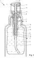
- Fig. 1 shows a schematic section of a proposed dispensing device 1 for dispensing a product or fluid 2. In the state shown, the dispensing device 1 is not actuated or the dispensing device 1 is in an initial or rest position.
- the dispensing device 1 preferably has a container 3 with or for the product 2 and / or a dispensing head 4 for dispensing the product 2 to a user (not shown).
- the dispensing head 4 is preferably connected or connectable to the container 3, in particular mechanically and / or fluidically.
- the dispensing device 1 has a (separate) closure 5, preferably with the dispensing head 4 being connected or connectable to the container 3 via the closure 5 in a form-fitting, non-positive and / or cohesive manner, in particular by screwing.
- the dispensing head 4 has or forms the closure 5 and / or the dispensing head 4 is or can be connected directly or directly to the container 3.
- the container 3 is preferably designed as a reservoir for the product 2.
- the dispensing device 1 or container 3 particularly preferably comprises a volume of more than 5 ml or 10 ml, in particular more than 50 ml or 100 ml, and / or less than 1000 ml or 800 ml, in particular less than 600 ml or 500 ml.
- the container 3 is preferably elongated, cylindrical and / or rigid.
- the container 3 is particularly preferably made of metal, plastic or glass.
- the dispensing device 1 has an optional bag 6, preferably with the bag 6 being arranged in the interior of the container 3 and / or containing the product 2.
- the optional bag 6 is preferably designed to be flexible or elastic.
- the bag 6 is compressible, preferably in such a way that the volume of the bag 6 (correspondingly) decreases with each dispensing of the product 2.
- other solutions are also possible here.
- the dispensing device 1 preferably has a pump 7, in particular of the type mentioned at the beginning.
- the pump 7 is particularly preferably designed as a displacement pump, in particular a metering pump or reciprocating piston pump.
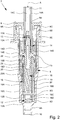
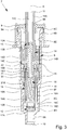
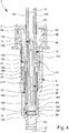
- FIGS. 2 to 4 each show a schematic section of the pump 7 in different states or positions.
- the pump 7 is preferably designed to suck or convey the product 2, in particular a predefined volume of the product 2, from the container 3 or the bag 6, to put it under pressure and / or to dispense it under pressure.
- the dispensing head 4 is particularly preferably fluidly connected or connectable to the container 3 via the pump 7.
- the pump 7 is preferably arranged at least partially in the interior of the container 3. In particular, the pump 7 extends from the dispensing head 4 into the container 3.
- the pump 7 is preferably connected or can be connected to the container 3 and / or dispensing head 4 in a form-fitting, force-fitting and / or material fit.
- the pump 7 is fastened to the container 3 via the closure 5 and the dispensing head 4 is plugged onto the pump 7.
- the pump 7 is integrated into the dispensing head 4 and / or has or forms the closure 5.
- the pump 7 preferably has a pump housing 8, a housing cover 9, an inlet 10, an outlet 11, an inlet valve 12, an outlet valve 13, a pump piston 14, a pump chamber 15 and / or a spring 16.
- the pump housing 8, the housing cover 9, the inlet 10, the outlet 11, the inlet valve 12, the outlet valve 13 and / or the pump piston are preferably / is 14, particularly preferably all parts or components of the pump 7 - except for the spring 16 - made of plastic and / or injection molded.
- the pump 7, in particular the pump housing 8, is preferably elongated and / or rotationally symmetrical.
- the pump 7 or the pump housing 8 has a longitudinal axis A, preferably the longitudinal axis A being an axis of rotation of the pump 7 or the pump housing 8.
- the pump housing 8 is preferably designed as a particularly elongated hollow cylinder.
- the pump 7 can preferably be flowed through axially or along the longitudinal axis A and / or from the inlet 10 to the outlet 11.
- the inlet 10 is preferably arranged on a first end of the pump 7, which is the lower end in the usual position of use of the dispensing device 1, and the outlet 11 is arranged on a second end of the pump 7, which is the upper end of the pump 7 in the usual position of use of the dispensing device 1.
- the inlet 10 and the outlet 11 preferably form the axial ends of the pump 7, in particular with the inlet 10 being assigned to the container 3 and the outlet 11 to the dispensing head 4.
- the product 2 or a predefined volume of the product 2 can preferably be fed to the pump chamber 15 via the inlet 10 and / or can be fed from the pump chamber 15 to the dispensing head 4 via the outlet 11.
- the inlet valve 12 is preferably assigned to the inlet 10 and / or arranged between the inlet 10 and the pump chamber 15.
- the outlet valve 13 is preferably assigned to the outlet 11 and / or is arranged between the outlet 11 and the pump chamber 15.
- the flow through the pump 7 can preferably be controlled by means of the inlet valve 12 and / or the outlet valve 13.
- the inlet valve 12 is preferably designed to allow the product 2 to flow from the container 3 into the pump chamber 15, in particular as a function from the pressure in the pump chamber 15, optionally to enable or prevent.
- the outlet valve 13 is preferably designed to selectively enable or prevent a flow of the product 2 from the pump chamber 15 to the outlet 11, in particular as a function of the pressure in the pump chamber 15, 15.
- the inlet valve 12 and / or the outlet valve 13 are designed as an automatically opening or automatically closing valve, preferably with the inlet valve 12 or the outlet valve 13 opening or closing depending on the pressure in the pump chamber 15.
- the pressure in the pump chamber 15 or the volume of the pump chamber 15 can preferably be changed by actuating the dispensing device 1 or pump 7 or by a stroke movement of the pump piston 14.
- the volume of the pump chamber 15 can be reduced by actuating the dispensing device 1 or moving the pump piston 14 downwards or in the direction of the container 3 and / or the pressure in the pump chamber 15 by actuating the dispensing device 1 or moving the pump piston 14 downwards or in the direction of the container 2 can be increased.
- the outlet valve 13 opens (automatically) when a certain pressure in the pump chamber 15 is exceeded or the pump chamber 15 is reduced by means of the pump piston 14 and / or closes the outlet valve 13 (automatically) when the pressure in the pump chamber 15 or below falls below a certain level. an enlargement of the pump chamber 15 by means of the pump piston 14.
- the inlet valve 12 opens when the pressure in the pump chamber 15 falls below a certain level or the pump chamber 15 is enlarged by means of the pump piston 14 and / or the inlet valve 12 closes (automatically) when a certain pressure in the pump chamber 15 is exceeded or when the pump chamber 15 is reduced the pump chamber 15 by means of the pump piston 14.
- valves 12, 13 can consequently be opened or closed as a function of the movement of the pump piston 14, in particular automatically, preferably whereby the outlet valve 13 and the inlet valve 12 can be opened or closed contrary to one another or can be actuated by the movement of the pump piston 14.
- the inlet valve 12, outlet valve 13, the pump piston 14, the pump chamber 15 and the spring 16 are preferably arranged at least partially in the pump housing 8 or encased by the pump housing 8.
- the inside diameter of the pump housing 8 tapers towards the container 3 or, in the usual position of use, of the dispensing device 1 downwards.
- the pump housing 8 preferably has a first (axial) end 8A, arranged at the bottom in the usual position of use of the dispensing device 1, and a second (axial) end 8B arranged at the top in the usual position of use of the dispensing device 1, preferably with the first end 8A and the second end 8B each have or form an (axial) opening of the pump housing 8.
- the pump housing 8 preferably the first end 8A, has or forms the inlet 10 and / or the pump housing 8 tapers in the direction of the container 3 to the inlet 10.
- the inner diameter of the inlet 10 or of the first end 8A is particularly preferably smaller than the inner diameter of the second end 8B.
- the inlet 10 is preferably designed as a connection or nipple for an optional riser pipe 17.
- the inlet 10 is preferably designed as a connection or nipple for an optional riser pipe 17.
- other solutions are also possible here.
- the (inner) components of the pump 7, such as the spring 16 or the pump piston 14, are preferably introduced or mounted into the pump housing 8 via the second end 8B.
- the housing cover 9 preferably closes the pump housing 8, in particular the second end 8B, particularly preferably axially.
- the housing cover 9 and the pump housing 8 are preferably connected to one another in a form-fitting, force-fitting and / or material fit.
- the housing cover 9 is plugged or latched onto the pump housing 8, in particular the second end 8B, and / or designed as a cap.
- the pump housing 8 preferably has a preferably circumferential (radial) projection or flange 8C, preferably with the projection or flange 8C in the housing cover 9, in particular in a recess or groove 9A corresponding to the projection or flange 8C of the housing cover 9 is engaged.
- the pump piston 14 is preferably elongated and / or preferably has an in particular elongated piston shaft 14A and / or a piston head 14B — in particular enlarged in comparison to the piston shaft 14A.
- the pump piston 14, in particular the piston shaft 14A, preferably protrudes from the pump housing 8 or the housing cover 9.
- the housing cover 9 particularly preferably has an (axial) opening 9B, preferably wherein the pump piston 14, in particular the piston shaft 14A, extends through the opening 9B of the housing cover 9 to the outside or towards the dispensing head 4.
- the pump piston 14 or piston shaft 14A has an (axial) outlet channel 14C, preferably wherein the outlet channel 14C opens into the outlet 11.
- the dispensing head 4 is preferably connected or connectable to the pump 7 in a form-fitting, force-fitting and / or material fit.
- the dispensing head 4 is plugged onto the pump 7, in particular the pump piston 14 or the piston shaft 14A.
- other solutions are also possible here.
- the pump piston 14 is preferably movable axially or along the longitudinal axis A, in particular in order to suck in the product 2 from the container 3 or to enlarge the pump chamber 15, to pressurize the sucked in product 2 in the pump chamber 15 or to close the pump chamber 15 and dispense via the outlet channel 14C or the outlet 11, in particular to or via the dispensing head 4.
- the pump piston 14 is preferably designed to execute a stroke movement in or relative to the pump housing 8.
- the pump piston 14 can be moved downwards or in the direction of the container 3 or inlet 10 by actuating or pressing down the dispensing head 4, in particular to reduce the size of the pump chamber 15 or to put the product 2 in the pump chamber 15 under pressure.
- the piston head 14B preferably has a larger diameter than the piston shaft 14A and / or the pump piston 14 is guided laterally or radially over the piston head 14B in the pump housing 8.
- the pump piston 14 or the piston head 14B preferably has a particularly circumferential guide surface 14D, preferably the guide surface 14D being in contact with the inner surface 8E of the pump housing 8 or being slidably movable over the inner surface 8E of the pump housing 8.
- the pump piston 14 or the piston head 14B preferably has an in particular circumferential seal 14E, preferably the seal 14E being in contact with the inner surface 8E of the pump housing 8, in particular such that the pump chamber 15 is sealed to the outside or axially or to the top .
- the seal 14E is preferably designed in one piece with the pump piston 14 or the pump piston 14, in particular the piston head 14B, forms the seal 14E.
- the seal 14E is designed as a piston ring and / or is embedded in a circumferential groove on the piston head 14B.
- the pump 7 preferably has at least one spring 16, in particular the spring 16 being designed as a helical spring and / or made of metal.
- the spring 16 is preferably arranged completely in the pump housing 8.
- the spring 16 is arranged at least substantially centrally in the pump housing 8 and / or coaxially to the pump housing 8 and / or the pump piston 14.
- the spring 16 is arranged eccentrically in the pump housing 8 and / or radially offset from the longitudinal axis A of the pump housing 8 or of the pump piston 14.
- the spring 16 is preferably counter-supported axially in the pump housing 8, in particular at the first end 8A of the pump housing 8, as will be explained in more detail below.
- the spring 16 is preferably compressible or compressible by actuating the dispensing head 4 or moving the pump piston 14 downward or in the direction of the inlet 10.
- the pump piston 14 is preferably pretensioned by means of the spring 16 and / or can be moved downward against the spring force of the spring 16 or in the direction of the spring 16, in particular to reduce the volume of the pump chamber 15 or the product 2 in the pump chamber 15 under pressure to be set and / or to be supplied from the pump chamber 15 via the outlet channel 14C to the outlet 11.
- the exact sequence of the pumping or lifting movement of the pump piston 14 is explained in greater detail below with reference to FIGS. 2 to 4 explained.
- An essential aspect of the present invention is to separate the spring 16 from the product 2 or to prevent (direct) contact between the spring 16 and the product 2, in particular independently of a pumping or lifting movement of the pump piston 14.
- the dispensing device 1 or the pump 7 has (for this) a - in particular removable - spring sleeve or capsule 18, with the spring 16 being arranged in the spring sleeve or capsule 18 and / or with the spring sleeve or capsule 18 the spring 16 separates and / or surrounds the product 2 or the pump chamber 15 or is arranged around the spring 16.
- the dispensing device 1 or the pump 7 has a preferably closed or sealed spring chamber 19, preferably wherein the spring 16 is arranged (completely) in the spring chamber 19 and / or the spring sleeve 18 has the spring chamber 19, forms or, in particular, radially and axially - limited.
- the spring sleeve 18 is preferably designed as a particularly closed or sealed housing and / or at least essentially rigid.
- the spring sleeve 18 is made or injection molded from plastic.
- the spring sleeve 18 or the spring chamber 19 is preferably elongated and / or cylindrical. Particularly preferably, the inner diameter of the spring sleeve 18 or the spring chamber 19 corresponds at least essentially to the outer diameter of the spring 16.
- the spring sleeve 18 or the spring chamber 19 is preferably filled with a compressible medium, in particular gas, particularly preferably air.
- the spring sleeve 18 or spring chamber 19 is preferably arranged centrally in the pump housing 8 and / or coaxially with the pump housing 8 or the pump piston 14.
- the pump chamber 15 extends - particularly preferably in the form of a ring - around the spring sleeve 18 or the spring chamber 19, in particular in such a way that the spring sleeve 18 or the spring chamber 19 can be flowed around.
- the pump chamber 15 is delimited laterally or radially by the spring sleeve 18 and by the pump housing 8 and / or the spring sleeve 18 forms an inner wall and the pump housing 8 forms an outer wall of the pump chamber 15.
- the pump housing 8 preferably has a receptacle 8F for - in particular radially and / or axially - receiving the spring sleeve 18, preferably wherein the receptacle 8F is arranged between the inlet 10 or the inlet valve 12 on the one hand and the pump chamber 15 or the pump piston 14 on the other .
- the pump chamber 15 preferably tapers in the direction of the container 3 or downwards to the receptacle 8F or the pump chamber 15 has a larger diameter than the receptacle 8F.
- the inner diameter of the receptacle 8F preferably corresponds at least essentially to the outer diameter of the spring sleeve 18 or the lower part of the spring sleeve 18, in particular such that the spring sleeve 18 is seated firmly or at least essentially free of play in the receptacle 8F of the pump housing 8.
- the spring sleeve 18 preferably protrudes from the receptacle 8F into the pump chamber 15 and / or the spring sleeve 18 extends from the receptacle 8F into the pump chamber 15.
- the spring sleeve 18 preferably has - at least at the end or in the region of the receptacle 8F - several, in particular elongated or rib-like projections 18A, preferably the projections 18A each extending parallel to the longitudinal axis A on the outside of the spring sleeve 18.
- the spring sleeve 18 preferably has, in particular at the end or in the region of the receptacle 8F, several guide channels 18B, preferably the guide channels 18B being formed by the projections 18A or laterally delimited by the projections 18A.
- the guide channels 18B fluidically connect the pump chamber 15 to the inlet 10 or inlet valve 12. In this way, the product 2 can flow from the inlet valve 12 into the pump chamber 15.
- the pump housing 8 or the receptacle 8F has projections and / or depressions in order to enable the product 2 to flow from the inlet valve 12 to the pump chamber 15.
- the bearing 8G is preferably formed by a step or rib-like projections - in particular around the inlet valve 12.
- the inlet valve 12 is preferably arranged between the pump chamber 15 and the inlet 10.
- the inlet valve 12 is particularly preferably arranged between the lower end of the spring sleeve 18 or the end assigned to the inlet 10 and the inlet 10.
- the inlet valve 12 preferably has a valve seat 12A and a valve body 12B, preferably wherein the valve body 12B can be moved relative to the valve seat 12A, in particular in order to open and close the inlet valve 12.
- the valve seat 12A is preferably formed by the pump housing 8, in particular by a step 8D of the pump housing 8.
- the valve body 12B can preferably be raised from the valve seat 12A, in particular when the pump chamber 15 is enlarged or the pressure in the pump chamber 15 is reduced, in particular in such a way that the inlet valve 12 opens.
- the valve body 12B can preferably be lowered onto the valve seat 12A, in particular when the pump chamber 15 is reduced in size or the pressure in the pump chamber 15 increases, particularly preferably in such a way that the inlet valve 12 closes.
- the spring sleeve 18 preferably has a limitation or a stop 18C or the spring sleeve 18 forms a limitation or a stop 18C for the inlet valve 12, in particular the valve body 12B.
- the limitation 18C is preferably designed to limit or restrict the movement of the valve body 12B.
- the delimitation 18C is particularly preferably formed by one or more — in particular axial — projections of the spring sleeve 18.
- the delimitation 18C is designed like a crown and / or the delimitation 18C preferably has a plurality of axial prongs or projections, preferably the teeth or projections pointing in the direction of the inlet valve 12 or valve body 12B.
- the prongs or projections reduce the delimitation surface or support surface for the valve body 12B, so that the valve body 12B is prevented from sticking to the delimitation 18C.
- the valve body 12B of the inlet valve 12 is preferably designed as a movable plate, preferably wherein the valve body 12B rises or falls as a function of the pressure in the pump chamber 15.
- the inlet valve 12 opens by lifting the valve body 12B from the valve seat 12A in the direction of the spring sleeve 18 or the limitation 18C, in particular when the pressure in the pump chamber 15 falls and / or the pump piston 14 moves upwards.
- the inlet valve 12 is designed as a diaphragm valve or the valve body 12B is designed as a particularly flexible diaphragm, preferably with the spring sleeve 18, in particular the delimitation 18C, preferably holding or clamping the valve body 12B axially and / or the inlet valve 12 can be opened by, in particular, deforming or lifting the valve body 12B at the edge.
- the spring sleeve 18 is preferably constructed in several parts and / or formed by several (separate) components or parts.
- the spring sleeve 18 has a base part 20 and a head part 21, preferably with the base part 20 in the usual position of use of the dispensing device 1 at the bottom or in the receptacle 8F and the head part 21 in the usual position of use of the dispensing device 1 at the top or in the pump chamber 15 .
- the base part 20 preferably forms a lower end of the spring sleeve 18 that faces the inlet 10, and the head part 21 forms an upper end of the spring sleeve 18 that faces the outlet 11.
- the base part 20 and the head part 2 completely or completely close the spring chamber 19. both axially and radially.
- the base part 20 is preferably designed to receive a first, in the usual position of use of the dispensing device 1, the lower end 16A of the spring 16 and the head part 21 to receive a second, in the usual position of use of the dispensing device, the upper end 16B of the spring 16.
- the spring sleeve 18 is preferably designed telescopically.
- the spring sleeve 18 or the spring chamber 19 can be compressed or compressed.
- the base part 20 and the head part 21 are preferably movable or displaceable relative to one another, in particular in order to enlarge or reduce the spring chamber 19.
- the base part 20 is immovable or fixed in the receptacle 8F relative to the pump housing 8 and / or the head part 21 is (axially) movable relative to the pump housing 8 or base part 20 and / or in the pump chamber 15.
- the spring sleeve 18 or the base part 20 and / or the head part 21 is / are at least substantially rigid.
- the spring sleeve 18 is designed to be elastically deformable.
- the spring sleeve 18 can be made of an elastic, compressible and / or foldable material in order to enable a stroke movement of the pump piston 14.
- the base part 20 and the head part 21 are preferably plugged into one another and / or the base part 20 and the head part 21 overlap, in particular in the area of the pump chamber 15.
- the head part 21 is preferably plugged onto the base part 20 or extends Base part 20 in the head part 27.
- other solutions are also possible, in particular in which the head part 21 is inserted into the base part 20.
- the spring sleeve 18, in particular the base part 20 and / or the head part 21, preferably has a guide or bearing pin 18D, preferably wherein the pin 18D protrudes axially into the spring chamber 19 and / or is designed to support the spring 16 or the second end 16B of the spring 16 to hold or to guide.
- the pin 18D is designed to stabilize the spring 16 and / or to prevent the spring 16 from buckling when the spring 16 or the spring sleeve 18 is compressed.
- the outer diameter of the head part 21 is preferably smaller than the inner diameter of the pump chamber 15, in particular such that a gap (through which a flow can flow) is formed between the head part 21 and the pump housing 8.
- a gap through which a flow can flow
- the head part 21 and / or the pump housing 8 preferably have / has rib-like projections and / or elongated depressions in order to allow the product 2 to flow through the pump chamber 15 or from the inlet 10 to the outlet 11 to enable.
- the head part 21 preferably has an in particular circumferential seal or sealing lip 21A for sealing the spring sleeve 18 or spring chamber 19.
- the seal 21A is designed to seal the spring chamber 19 with respect to the pump chamber 15.
- the seal 21A preferably rests radially on the base part 20, in particular in such a way that the seal 21A is pressed (further) against the base part 20 by an increase in pressure in the pump chamber 15. This ensures that the spring chamber 19 is sealed in spite of a pressure increase in the pump chamber 15.
- the pump 7 preferably has a connecting element 22, preferably the connecting element 22 connecting the pump piston 14 (mechanically) to the spring 16 or the spring sleeve 18, in particular the head part 21.
- the connecting element 22 is preferably elongated and / or preferably extends from the outlet valve 13 into the pump chamber 15.
- the connecting element 22 and the pump piston 14 preferably form the outlet valve 13, in particular the pump piston 14 having or forming the valve seat 13A and the connecting element 22 having or forming the valve body 13B of the outlet valve 13.
- the connecting element 22 tapers upwards or in the direction of the dispensing head 4 to the valve body 13B and / or the connecting element 22 has a conical or conical end which has or forms the valve body 13B or a valve cone as valve body 13B.
- the connecting element 22 and the spring sleeve 18, in particular the head part 21, are preferably firmly, preferably positively and / or non-positively connected to one another.
- the connecting element 22 and the head part 21 are designed as separate components.
- solutions are also possible here in which the head part 21 and the connecting element 22 are formed in one piece or form a structural unit.
- the connecting element 22 is preferably made of plastic or is injection molded.
- the connecting element 22 preferably extends into the spring sleeve 18 or through the head part 21 into the spring chamber 19.
- the connecting element 22 has the pin 18D and / or forms the connecting element 22, in particular a lower, the end of the connecting element 22 associated with the spring sleeve 18, the pin 18D.
- the head part 21 has or forms the pin 18D.
- the connecting element 22 is preferably movable downward relative to the pump piston 14 or in the usual position of use of the dispensing device 1, preferably around the outlet valve 13, in particular after a predetermined pressure in the pump chamber 15 is exceeded or by actuating the dispensing device 1 or the dispensing head 4 open or lift the valve body 13B from the valve seat 13A and / or feed the product 2 from the pump chamber 15 to the outlet 11.
- the connecting element 22 and the head part 21 can be moved together against the spring force of the spring 16 in order to open the outlet valve 13 and enable the product 2 to be dispensed from the pump chamber 14.
- Fig. 1 shows the dispensing device 1 or the pump 7 in the non-actuated state or in a starting position.
- Fig. 2 shows the pump 7 during actuation or during the delivery of the product 2.
- Fig. 3 shows the pump 7 in an end position in which the pump piston 14 or the connecting element 22 is moved completely downwards or in the direction of the inlet 10.
- Fig. 4 shows the pump 7 when the pump piston 14 is returned to the starting position or during the suction or filling of the pump chamber 5 with the product 2.
- the starting or rest position of the dispensing device 1 or the pump 7 is preferably that position that the pump 7, in particular the pump piston 14 or the head part 21 or the connecting element 22, in the non-actuated state and / or automatically or by the The spring force of the spring 16 assumes.
- the volume of the pump chamber 15 is maximum and / or the spring 16 presses the pump piston 14, the head part 21 and / or the connecting element 22 upwards or against the pump housing 8 or the housing cover 9.
- the starting position or a movement of the pump piston 14 beyond the starting position is preferably limited by the stop of the pump piston 14, in particular the piston head 14B, against the pump housing 8 or the housing cover 9 (axially or upwards).
- the end position is preferably that position which the pump 7, in particular the pump piston 14 or the head part 21 or the connecting element 22, assumes when the pump 7 is fully actuated.
- the pump piston 14 or the head part 21 or the connecting element 22 is moved or pressed completely downwards or in the direction of the inlet 10 in the end position.
- the volume of the pump chamber 15 is minimal and / or smaller than in the starting position.
- the end position or a movement of the pump piston 14 beyond the end position is preferably limited by the stop of the connecting element 22 or the head part 21 against the base part 20 and / or the pump housing 8 (axially or downwards).
- the pump 7 is preferably removed from the starting position by (manually) actuating or depressing the dispensing head 4, as in FIG Fig. 1 shown in the end position, as in Fig. 3 shown, transferable.
- the spring 16 is preferably designed to transfer the pump 7, in particular by means of spring force or automatically, from the end position to the starting position. In particular, the spring 16 automatically resets the pump 7 or the pump piston 14 to the starting position after the pump 7 has been actuated.
- the pump piston 14 or the connecting element 22 or the head part 21 are or is preferably prestressed in the starting position by means of the spring 16.
- the spring 16 presses the head part 21 or the connecting element 22 or the pump piston 14 against the pump housing 8 or the housing cover 9.
- the pump piston 14, in particular together with the head part 21 or the connecting element 22, can be moved against the spring force of the spring 16 or, in the usual position of use, downwards or in the direction of the container 3, preferably whereby the volume of the pump chamber 15 is reduced and / or the pressure in the pump chamber 15 is increased, as already explained.
- the inlet valve 12 is (automatically) closed and / or the valve body 12B is pressed against the valve seat 12A, in particular in such a way that the product 2 in the pump chamber 15 does not return can flow into the container 3.
- the head part 21 is preferably moved relative to the base part 20 and / or the spring chamber 19 is reduced in size and / or the gas pressure in the spring chamber 19 is increased.
- the spring sleeve 16 or the spring chamber 19 is preferably designed in such a way that no gas or no air escapes from the spring chamber 19 into the pump chamber 15, even with or despite an increase in pressure due to compression of the spring chamber 19.
- the outlet valve 13 is designed to open automatically when a predetermined pressure in the pump chamber 15 is exceeded.
- an increase in pressure in the pump chamber 15 or an actuation of the dispensing device 1 or the dispensing head 4 or the pump 7 causes the valve body 13B or the connecting element 22 to move relative to the valve seat 13A or to the pump piston 14 or away from it
- Valve seat 13A or pump piston 14 lifts off, preferably in such a way that outlet valve 13 opens and / or product 2 can flow from pump chamber 15 through outlet valve 13 into outlet channel 14C of pump piston 14, as in FIG Fig. 2 indicated by arrows.
- the opening of the outlet valve 13 causes a pressure drop in the pump chamber 15, preferably such that the outlet valve 13 would close again without further actuation of the dispensing device 1.
- the volume of the pump chamber 15 is further reduced or the product 2 in the pump chamber 15 is pressurized, preferably in such a way that the outlet valve 13 remains open for as long until the end position, as in Fig. 3 shown, is achieved.
- the dispensing process is completed and / or the outlet valve 13 closes, in particular in that the pump housing 8 and / or the base part 20 press the valve body 13B or the connecting element 22 or the head part 21 against the valve seat 13A or . the pump piston 14 presses.
- the pump chamber 15 is preferably filled automatically.
- the spring 16 pushes the pump piston 14 or the head part 21 or the connecting element 22 again upwards or in the direction of the dispensing head 4 or into the starting position.
- the volume of the pump chamber 15 is increased and / or the pressure is reduced by increasing the volume of the pump chamber 15, preferably thereby the inlet valve 12 opens or the valve body 12B is lifted from the valve seat 12A, as in FIG Fig. 4 shown.
- the volume of the spring chamber 19 also increases and / or the head part 21 moves relative to the base part 20 or upwards.
- the product 2 flows when the pump piston 14 is returned to the starting position through the inlet valve 12 laterally past the spring sleeve 18 into the pump chamber 15, in particular without coming into (direct) contact with the spring 16.
- the outlet valve 13 is or remains closed during the (entire) movement of the pump piston 14 upwards or into the starting position.
- the filling of the pump chamber 15 is complete.
- the product 2 located in the pump chamber 15 can then be dispensed, as already explained.
- the proposed dispensing device 1 or pump 7 enables the spring 16 - in particular independently of a pumping or lifting movement of the pump 7 - to be separated from the product 2 and / or the spring chamber 19 - in particular independent of a pumping or lifting movement of the Pump 7 - is sealed.
Landscapes
- Reciprocating Pumps (AREA)
- Containers And Packaging Bodies Having A Special Means To Remove Contents (AREA)
- Closures For Containers (AREA)
Claims (15)
- Pompe (7) pour un produit (2) de préférence liquide,
dans laquelle la pompe (7) comprend un boîtier de pompe (8), un piston de pompe (14), une chambre de pompe (15), un ressort (16), une entrée (10), une sortie (11), une soupape d'entrée (12) et une soupape de sortie (13),
dans laquelle le piston de pompe (14), la chambre de pompe (15), le ressort (16), la soupape d'entrée (12) et la soupape de sortie (13) sont disposés au moins partiellement dans le boîtier de pompe(8),
dans laquelle le piston de pompe (14) est mobile axialement dans le boîtier de pompe (8) pour refouler le produit (2) par l'entrée (10) dans la chambre de pompe (15) et de la chambre de pompe (15) à la sortie (11),
dans laquelle le piston de pompe (14) est précontraint au moyen du ressort (16) dans une position initiale et est déplaçable à l'encontre de la force du ressort (16) dans une position finale afin de mettre sous pression le produit (2) dans la chambre de pompe (15),
caractérisée
en ce que la pompe (7) comporte une douille à ressort (18) autour du ressort (16), la douille à ressort (18) séparant le ressort (16) du produit (2), et la chambre de pompe (15) s'étendant - en particulier de manière annulaire - autour de la douille à ressort (18), de sorte que le produit (2) peut s'écouler autour de la douille à ressort (18), et/ou
en ce que la pompe (7) présente une chambre à ressort (19) étanche pour le ressort (16), le ressort (16) étant disposé dans la chambre à ressort (19) et la chambre de pompe (15) s'étendant - en particulier de manière annulaire - autour de la chambre à ressort (19), de sorte que le produit (2) peut s'écouler autour de la chambre à ressort (19). - Pompe selon la revendication 1, caractérisée en ce que la chambre de pompe (15) est délimitée latéralement par la douille à ressort (18) et le boîtier de pompe (8).
- Pompe selon la revendication 1 ou 2, caractérisée en ce que la douille à ressort (18) étanche et/ou limite latéralement la chambre à ressort (19).
- Pompe selon l'une des revendications précédentes, caractérisée en ce que la douille à ressort (18) entoure complètement le ressort (16).
- Pomper selon l'une des revendications précédentes, caractérisé en ce que la douille à ressort (18) sépare le ressort (16) du produit (2) indépendamment d'un mouvement de pompage et/ou que la chambre à ressort (19) est étanche indépendamment d'un mouvement de pompage.
- Pompe selon l'une des revendications précédentes, caractérisée en ce que la douille à ressort (18) est réalisé en plusieurs parties et/ou télescopique ou compressible.
- Pompe selon l'une des revendications précédentes, caractérisée en ce que la chambre à ressort (19) est compressible et/ou écrasable.
- Pompe selon l'une des revendications précédentes, caractérisée en ce que la pompe (7) comprend un élément de liaison (22) reliant mécaniquement le piston de pompe (14) à la douille à ressort (18) et/ou au ressort (16).
- Pompe selon la revendication 8, caractérisée en ce que l'élément de liaison (22) et le piston de pompe (14) forment la soupape de sortie (13) et/ou l'élément de liaison (22) - en particulier après avoir dépassé une pression prédéterminée dans la chambre de pompe (15) - est mobile par rapport au piston de pompe (14), de préférence pour ouvrir la soupape de sortie (13) et/ou pour dispenser le produit (2) par la sortie (11).
- Pompe selon l'une des revendications précédentes, caractérisée en ce que la douille à ressort (18) comprend une partie de base (20) et une partie de tête (21).
- Pompe selon les revendications 8 et 10, caractérisée en ce que la partie de tête (21) et l'élément de liaison (22) sont formés d'une seule pièce ou forment une unité structurelle et/ou sont reliés solidement l'un à l'autre, de préférence par engagement positif, et/ou sont précontraints ensemble dans la position de départ au moyen du ressort (16) ou peuvent être déplacés à l'encontre de la force du ressort (16).
- Pompe selon la revendication 10 ou 11, caractérisée en ce que la partie de base (20) et la partie de tête (21) sont mobiles l'une par rapport à l'autre ou de manière télescopique et/ou la partie de tête (21) est reliée de manière étanche à la partie de base (20).
- Une pompe selon l'une des revendications précédentes, caractérisée en ce que la soupape d'entrée (12) est disposée entre l'entrée (10) et la chambre de pompe (15).
- Pompe selon la revendication 13, caractérisée en ce que la soupape d'entrée (12) s'ouvre automatiquement lors d'un élargissement de la chambre de pompe (15) et/ou d'un mouvement du piston de pompe (14) de la position finale à la position initiale.
- Dispositif de distribution (1) pour distribuer un produit (2) de préférence liquide, le dispositif de distribution(1) comprenant une tête de distribution (4), une pompe (7) et un récipient (3) contenant ou pour le produit (2),
dans lequel la tête de distribution (4) est reliée fluidiquement au récipient (3) par la pompe (7),
caractérisé
en ce que la pompe (7) est conçue selon l'une des revendications précédentes.
Applications Claiming Priority (3)
| Application Number | Priority Date | Filing Date | Title |
|---|---|---|---|
| DE202016007502 | 2016-12-12 | ||
| DE102016014898.5A DE102016014898A1 (de) | 2016-12-12 | 2016-12-15 | Pumpe und Abgabevorrichtung |
| PCT/EP2017/080842 WO2018108535A1 (fr) | 2016-12-12 | 2017-11-29 | Pompe et dispositif de distribution |
Publications (2)
| Publication Number | Publication Date |
|---|---|
| EP3551343A1 EP3551343A1 (fr) | 2019-10-16 |
| EP3551343B1 true EP3551343B1 (fr) | 2021-06-16 |
Family
ID=62201237
Family Applications (1)
| Application Number | Title | Priority Date | Filing Date |
|---|---|---|---|
| EP17808857.1A Active EP3551343B1 (fr) | 2016-12-12 | 2017-11-29 | Pompe et dispositif de distribution |
Country Status (6)
| Country | Link |
|---|---|
| US (1) | US10953420B2 (fr) |
| EP (1) | EP3551343B1 (fr) |
| AR (1) | AR110339A1 (fr) |
| DE (1) | DE102016014898A1 (fr) |
| ES (1) | ES2883680T3 (fr) |
| WO (1) | WO2018108535A1 (fr) |
Families Citing this family (4)
| Publication number | Priority date | Publication date | Assignee | Title |
|---|---|---|---|---|
| KR102140284B1 (ko) * | 2018-09-06 | 2020-07-31 | 임종수 | 액상 화장품의 미스트 분사기구 |
| FR3111337B1 (fr) * | 2020-06-12 | 2022-06-03 | Aptar France Sas | Organe de fixation de pompe |
| WO2023139260A1 (fr) | 2022-01-24 | 2023-07-27 | Aptar Dortmund Gmbh | Ressort de soupape, pompe, unité de distribution et distributeur |
| DE102022114583A1 (de) | 2022-06-09 | 2023-12-14 | Peter Kwasny Gmbh | Wässrige Sprühlackformulierung |
Family Cites Families (18)
| Publication number | Priority date | Publication date | Assignee | Title |
|---|---|---|---|---|
| US3249259A (en) * | 1964-08-03 | 1966-05-03 | Calmar Inc | Reciprocating pump type dispenser |
| US4034900A (en) | 1976-05-03 | 1977-07-12 | Ethyl Corporation | Spray pump assembly |
| US4154374A (en) | 1977-10-03 | 1979-05-15 | Ethyl Products Company | Finger operated spray pump |
| ES2011140A6 (es) | 1988-10-10 | 1989-12-16 | Monturas Sa | Bomba pulverizadora. |
| DE4035663A1 (de) * | 1990-11-09 | 1992-05-14 | Pfeiffer Erich Gmbh & Co Kg | Austragvorrichtung fuer medien |
| CN1385247A (zh) | 2001-05-11 | 2002-12-18 | 增田胜利 | 流动体喷出泵 |
| JP4210215B2 (ja) * | 2001-09-21 | 2009-01-14 | インジ エリッヒ プファイファ ゲーエムベーハ | 媒体リザーバを備えた投与装置とこれのためのポンプ装置 |
| DE10335842C5 (de) | 2003-08-05 | 2011-04-28 | Seaquist Perfect Dispensing Gmbh | Abgabepackung |
| FR2862107B1 (fr) | 2003-11-07 | 2006-02-10 | Valois Sas | Pompe de distribution de produit fluide. |
| KR100569180B1 (ko) | 2004-04-29 | 2006-04-10 | 주식회사 종우실업 | 소형 수동식 펌프 |
| FR2885887B1 (fr) | 2005-05-20 | 2010-11-05 | Rexam Dispensing Sys | Pompe a pointeau pour la distribution de produit liquide |
| CN100494008C (zh) * | 2006-06-15 | 2009-06-03 | 丁要武 | 弹簧外置式乳液泵 |
| CN101209766A (zh) * | 2006-12-27 | 2008-07-02 | 株式会社衍宇 | 泵童子 |
| FR2917651B1 (fr) | 2007-06-20 | 2010-09-17 | Rexam Dispensing Sys | Pompe pour la distribution d'un produit liquide a amorcage ameliore |
| DE102010063587B4 (de) | 2010-12-20 | 2018-03-15 | Aptar Radolfzell Gmbh | Austragvorrichtung für eine Flüssigkeit |
| FR2973015B1 (fr) | 2011-03-25 | 2013-04-26 | Valois Sas | Pompe de distribution de produit fluide. |
| KR101233080B1 (ko) * | 2011-09-20 | 2013-02-14 | (주)연우 | 스프레이 펌프 |
| JP6466714B2 (ja) | 2011-09-20 | 2019-02-06 | ディスペンシング・テクノロジーズ・ベスローテン・フェンノートシャップDispensing Technologies B.V. | エアロゾル機能を有する計量型及び作動型スプレー装置(「フレアロゾルii」) |
-
2016
- 2016-12-15 DE DE102016014898.5A patent/DE102016014898A1/de not_active Withdrawn
-
2017
- 2017-11-29 WO PCT/EP2017/080842 patent/WO2018108535A1/fr not_active Ceased
- 2017-11-29 ES ES17808857T patent/ES2883680T3/es active Active
- 2017-11-29 EP EP17808857.1A patent/EP3551343B1/fr active Active
- 2017-11-29 US US16/464,804 patent/US10953420B2/en active Active
- 2017-12-12 AR ARP170103453A patent/AR110339A1/es active IP Right Grant
Also Published As
| Publication number | Publication date |
|---|---|
| EP3551343A1 (fr) | 2019-10-16 |
| ES2883680T3 (es) | 2021-12-09 |
| US20190344297A1 (en) | 2019-11-14 |
| US10953420B2 (en) | 2021-03-23 |
| AR110339A1 (es) | 2019-03-20 |
| WO2018108535A1 (fr) | 2018-06-21 |
| DE102016014898A1 (de) | 2018-06-14 |
Similar Documents
| Publication | Publication Date | Title |
|---|---|---|
| DE60035828T2 (de) | Austragsventileinrichtung für eine hebelbetätigte Sprühvorrichtung | |
| DE69503369T2 (de) | Pumpe mit vordruckaufbau | |
| DE2454097C3 (de) | Handbetätigter Kleinzerstäuber | |
| DE69418907T2 (de) | Ausgabevorrichtung | |
| EP0492363B1 (fr) | Valve d'aspiration et/ou de refoulement pour une pompe de dosage ou de pulvérisation de produits liquides, à basse viscosité et pâteux | |
| EP1327478B1 (fr) | Poussoir d'une pompe aspirante et foulante pour la pulvérisation d'une produit contenu dans un récipient | |
| DE2903496C2 (fr) | ||
| DE3018840C2 (de) | Zerstäuber für Flüssigkeiten | |
| EP3551343B1 (fr) | Pompe et dispositif de distribution | |
| DE2001921A1 (de) | Hin- und herbewegte Fluessigkeitsabgabepumpe | |
| DE10220557A1 (de) | Spender zum Austrag fließfähiger Medien | |
| DE3105371A1 (de) | Fluessigkeitsspender | |
| DE3114873A1 (de) | Pumpe zur fluessigkeitsabgabe | |
| DE69821495T2 (de) | Handpumpe mit durch Plastikfedern beaufschlagtem Freikolben | |
| DE10231751B4 (de) | Saug-Druck-Pumpe zum Ausspritzen eines Produkts aus einem Behältnis | |
| EP3094416A1 (fr) | Distributeur de liquide | |
| DE102011106261A1 (de) | Spender zur dosierten Abgabe von flüssigen Medien | |
| EP3359298B1 (fr) | Distributeur de produit liquide ou pâteux | |
| EP2747893B1 (fr) | Distributeur de produit pâteux | |
| EP2634112A1 (fr) | Récipient de sortie pouvant être rempli de nouveau | |
| DE20110604U1 (de) | Spender für pastöses Produkt | |
| DE69624642T2 (de) | Pumpenmechanismus | |
| WO2019011622A1 (fr) | Distributeur de liquide | |
| DE69100307T2 (de) | Vordruck-Handpumpe. | |
| EP0484835B1 (fr) | Distributeur de fluide |
Legal Events
| Date | Code | Title | Description |
|---|---|---|---|
| STAA | Information on the status of an ep patent application or granted ep patent |
Free format text: STATUS: UNKNOWN |
|
| STAA | Information on the status of an ep patent application or granted ep patent |
Free format text: STATUS: THE INTERNATIONAL PUBLICATION HAS BEEN MADE |
|
| PUAI | Public reference made under article 153(3) epc to a published international application that has entered the european phase |
Free format text: ORIGINAL CODE: 0009012 |
|
| STAA | Information on the status of an ep patent application or granted ep patent |
Free format text: STATUS: REQUEST FOR EXAMINATION WAS MADE |
|
| 17P | Request for examination filed |
Effective date: 20190510 |
|
| AK | Designated contracting states |
Kind code of ref document: A1 Designated state(s): AL AT BE BG CH CY CZ DE DK EE ES FI FR GB GR HR HU IE IS IT LI LT LU LV MC MK MT NL NO PL PT RO RS SE SI SK SM TR |
|
| AX | Request for extension of the european patent |
Extension state: BA ME |
|
| DAV | Request for validation of the european patent (deleted) | ||
| DAX | Request for extension of the european patent (deleted) | ||
| GRAP | Despatch of communication of intention to grant a patent |
Free format text: ORIGINAL CODE: EPIDOSNIGR1 |
|
| STAA | Information on the status of an ep patent application or granted ep patent |
Free format text: STATUS: GRANT OF PATENT IS INTENDED |
|
| INTG | Intention to grant announced |
Effective date: 20210127 |
|
| GRAS | Grant fee paid |
Free format text: ORIGINAL CODE: EPIDOSNIGR3 |
|
| GRAA | (expected) grant |
Free format text: ORIGINAL CODE: 0009210 |
|
| STAA | Information on the status of an ep patent application or granted ep patent |
Free format text: STATUS: THE PATENT HAS BEEN GRANTED |
|
| AK | Designated contracting states |
Kind code of ref document: B1 Designated state(s): AL AT BE BG CH CY CZ DE DK EE ES FI FR GB GR HR HU IE IS IT LI LT LU LV MC MK MT NL NO PL PT RO RS SE SI SK SM TR |
|
| REG | Reference to a national code |
Ref country code: GB Ref legal event code: FG4D Free format text: NOT ENGLISH |
|
| REG | Reference to a national code |
Ref country code: CH Ref legal event code: EP |
|
| REG | Reference to a national code |
Ref country code: DE Ref legal event code: R096 Ref document number: 502017010702 Country of ref document: DE |
|
| REG | Reference to a national code |
Ref country code: AT Ref legal event code: REF Ref document number: 1401882 Country of ref document: AT Kind code of ref document: T Effective date: 20210715 |
|
| REG | Reference to a national code |
Ref country code: IE Ref legal event code: FG4D Free format text: LANGUAGE OF EP DOCUMENT: GERMAN |
|
| REG | Reference to a national code |
Ref country code: LT Ref legal event code: MG9D |
|
| PG25 | Lapsed in a contracting state [announced via postgrant information from national office to epo] |
Ref country code: LT Free format text: LAPSE BECAUSE OF FAILURE TO SUBMIT A TRANSLATION OF THE DESCRIPTION OR TO PAY THE FEE WITHIN THE PRESCRIBED TIME-LIMIT Effective date: 20210616 Ref country code: FI Free format text: LAPSE BECAUSE OF FAILURE TO SUBMIT A TRANSLATION OF THE DESCRIPTION OR TO PAY THE FEE WITHIN THE PRESCRIBED TIME-LIMIT Effective date: 20210616 Ref country code: BG Free format text: LAPSE BECAUSE OF FAILURE TO SUBMIT A TRANSLATION OF THE DESCRIPTION OR TO PAY THE FEE WITHIN THE PRESCRIBED TIME-LIMIT Effective date: 20210916 Ref country code: HR Free format text: LAPSE BECAUSE OF FAILURE TO SUBMIT A TRANSLATION OF THE DESCRIPTION OR TO PAY THE FEE WITHIN THE PRESCRIBED TIME-LIMIT Effective date: 20210616 |
|
| REG | Reference to a national code |
Ref country code: NL Ref legal event code: MP Effective date: 20210616 |
|
| PG25 | Lapsed in a contracting state [announced via postgrant information from national office to epo] |
Ref country code: SE Free format text: LAPSE BECAUSE OF FAILURE TO SUBMIT A TRANSLATION OF THE DESCRIPTION OR TO PAY THE FEE WITHIN THE PRESCRIBED TIME-LIMIT Effective date: 20210616 Ref country code: RS Free format text: LAPSE BECAUSE OF FAILURE TO SUBMIT A TRANSLATION OF THE DESCRIPTION OR TO PAY THE FEE WITHIN THE PRESCRIBED TIME-LIMIT Effective date: 20210616 Ref country code: LV Free format text: LAPSE BECAUSE OF FAILURE TO SUBMIT A TRANSLATION OF THE DESCRIPTION OR TO PAY THE FEE WITHIN THE PRESCRIBED TIME-LIMIT Effective date: 20210616 Ref country code: NO Free format text: LAPSE BECAUSE OF FAILURE TO SUBMIT A TRANSLATION OF THE DESCRIPTION OR TO PAY THE FEE WITHIN THE PRESCRIBED TIME-LIMIT Effective date: 20210916 Ref country code: GR Free format text: LAPSE BECAUSE OF FAILURE TO SUBMIT A TRANSLATION OF THE DESCRIPTION OR TO PAY THE FEE WITHIN THE PRESCRIBED TIME-LIMIT Effective date: 20210917 |
|
| REG | Reference to a national code |
Ref country code: ES Ref legal event code: FG2A Ref document number: 2883680 Country of ref document: ES Kind code of ref document: T3 Effective date: 20211209 |
|
| PG25 | Lapsed in a contracting state [announced via postgrant information from national office to epo] |
Ref country code: SM Free format text: LAPSE BECAUSE OF FAILURE TO SUBMIT A TRANSLATION OF THE DESCRIPTION OR TO PAY THE FEE WITHIN THE PRESCRIBED TIME-LIMIT Effective date: 20210616 Ref country code: SK Free format text: LAPSE BECAUSE OF FAILURE TO SUBMIT A TRANSLATION OF THE DESCRIPTION OR TO PAY THE FEE WITHIN THE PRESCRIBED TIME-LIMIT Effective date: 20210616 Ref country code: EE Free format text: LAPSE BECAUSE OF FAILURE TO SUBMIT A TRANSLATION OF THE DESCRIPTION OR TO PAY THE FEE WITHIN THE PRESCRIBED TIME-LIMIT Effective date: 20210616 Ref country code: CZ Free format text: LAPSE BECAUSE OF FAILURE TO SUBMIT A TRANSLATION OF THE DESCRIPTION OR TO PAY THE FEE WITHIN THE PRESCRIBED TIME-LIMIT Effective date: 20210616 Ref country code: NL Free format text: LAPSE BECAUSE OF FAILURE TO SUBMIT A TRANSLATION OF THE DESCRIPTION OR TO PAY THE FEE WITHIN THE PRESCRIBED TIME-LIMIT Effective date: 20210616 Ref country code: RO Free format text: LAPSE BECAUSE OF FAILURE TO SUBMIT A TRANSLATION OF THE DESCRIPTION OR TO PAY THE FEE WITHIN THE PRESCRIBED TIME-LIMIT Effective date: 20210616 Ref country code: PT Free format text: LAPSE BECAUSE OF FAILURE TO SUBMIT A TRANSLATION OF THE DESCRIPTION OR TO PAY THE FEE WITHIN THE PRESCRIBED TIME-LIMIT Effective date: 20211018 |
|
| PG25 | Lapsed in a contracting state [announced via postgrant information from national office to epo] |
Ref country code: PL Free format text: LAPSE BECAUSE OF FAILURE TO SUBMIT A TRANSLATION OF THE DESCRIPTION OR TO PAY THE FEE WITHIN THE PRESCRIBED TIME-LIMIT Effective date: 20210616 |
|
| REG | Reference to a national code |
Ref country code: DE Ref legal event code: R097 Ref document number: 502017010702 Country of ref document: DE |
|
| PLBE | No opposition filed within time limit |
Free format text: ORIGINAL CODE: 0009261 |
|
| STAA | Information on the status of an ep patent application or granted ep patent |
Free format text: STATUS: NO OPPOSITION FILED WITHIN TIME LIMIT |
|
| PG25 | Lapsed in a contracting state [announced via postgrant information from national office to epo] |
Ref country code: DK Free format text: LAPSE BECAUSE OF FAILURE TO SUBMIT A TRANSLATION OF THE DESCRIPTION OR TO PAY THE FEE WITHIN THE PRESCRIBED TIME-LIMIT Effective date: 20210616 |
|
| 26N | No opposition filed |
Effective date: 20220317 |
|
| PG25 | Lapsed in a contracting state [announced via postgrant information from national office to epo] |
Ref country code: AL Free format text: LAPSE BECAUSE OF FAILURE TO SUBMIT A TRANSLATION OF THE DESCRIPTION OR TO PAY THE FEE WITHIN THE PRESCRIBED TIME-LIMIT Effective date: 20210616 |
|
| PG25 | Lapsed in a contracting state [announced via postgrant information from national office to epo] |
Ref country code: MC Free format text: LAPSE BECAUSE OF FAILURE TO SUBMIT A TRANSLATION OF THE DESCRIPTION OR TO PAY THE FEE WITHIN THE PRESCRIBED TIME-LIMIT Effective date: 20210616 |
|
| REG | Reference to a national code |
Ref country code: CH Ref legal event code: PL |
|
| PG25 | Lapsed in a contracting state [announced via postgrant information from national office to epo] |
Ref country code: LU Free format text: LAPSE BECAUSE OF NON-PAYMENT OF DUE FEES Effective date: 20211129 Ref country code: BE Free format text: LAPSE BECAUSE OF NON-PAYMENT OF DUE FEES Effective date: 20211130 |
|
| REG | Reference to a national code |
Ref country code: BE Ref legal event code: MM Effective date: 20211130 |
|
| PG25 | Lapsed in a contracting state [announced via postgrant information from national office to epo] |
Ref country code: IE Free format text: LAPSE BECAUSE OF NON-PAYMENT OF DUE FEES Effective date: 20211129 |
|
| P01 | Opt-out of the competence of the unified patent court (upc) registered |
Effective date: 20230517 |
|
| PG25 | Lapsed in a contracting state [announced via postgrant information from national office to epo] |
Ref country code: CY Free format text: LAPSE BECAUSE OF FAILURE TO SUBMIT A TRANSLATION OF THE DESCRIPTION OR TO PAY THE FEE WITHIN THE PRESCRIBED TIME-LIMIT Effective date: 20210616 |
|
| PG25 | Lapsed in a contracting state [announced via postgrant information from national office to epo] |
Ref country code: LI Free format text: LAPSE BECAUSE OF NON-PAYMENT OF DUE FEES Effective date: 20220630 Ref country code: HU Free format text: LAPSE BECAUSE OF FAILURE TO SUBMIT A TRANSLATION OF THE DESCRIPTION OR TO PAY THE FEE WITHIN THE PRESCRIBED TIME-LIMIT; INVALID AB INITIO Effective date: 20171129 Ref country code: CH Free format text: LAPSE BECAUSE OF NON-PAYMENT OF DUE FEES Effective date: 20220630 |
|
| REG | Reference to a national code |
Ref country code: AT Ref legal event code: MM01 Ref document number: 1401882 Country of ref document: AT Kind code of ref document: T Effective date: 20221129 |
|
| PG25 | Lapsed in a contracting state [announced via postgrant information from national office to epo] |
Ref country code: AT Free format text: LAPSE BECAUSE OF NON-PAYMENT OF DUE FEES Effective date: 20221129 |
|
| PG25 | Lapsed in a contracting state [announced via postgrant information from national office to epo] |
Ref country code: MK Free format text: LAPSE BECAUSE OF FAILURE TO SUBMIT A TRANSLATION OF THE DESCRIPTION OR TO PAY THE FEE WITHIN THE PRESCRIBED TIME-LIMIT Effective date: 20210616 |
|
| PG25 | Lapsed in a contracting state [announced via postgrant information from national office to epo] |
Ref country code: MT Free format text: LAPSE BECAUSE OF FAILURE TO SUBMIT A TRANSLATION OF THE DESCRIPTION OR TO PAY THE FEE WITHIN THE PRESCRIBED TIME-LIMIT Effective date: 20210616 |
|
| PGFP | Annual fee paid to national office [announced via postgrant information from national office to epo] |
Ref country code: DE Payment date: 20241121 Year of fee payment: 8 |
|
| PGFP | Annual fee paid to national office [announced via postgrant information from national office to epo] |
Ref country code: GB Payment date: 20241120 Year of fee payment: 8 |
|
| PGFP | Annual fee paid to national office [announced via postgrant information from national office to epo] |
Ref country code: FR Payment date: 20241128 Year of fee payment: 8 |
|
| PGFP | Annual fee paid to national office [announced via postgrant information from national office to epo] |
Ref country code: IT Payment date: 20241126 Year of fee payment: 8 Ref country code: ES Payment date: 20241230 Year of fee payment: 8 |
|
| PG25 | Lapsed in a contracting state [announced via postgrant information from national office to epo] |
Ref country code: TR Free format text: LAPSE BECAUSE OF FAILURE TO SUBMIT A TRANSLATION OF THE DESCRIPTION OR TO PAY THE FEE WITHIN THE PRESCRIBED TIME-LIMIT Effective date: 20210616 |