EP3551343B1 - Pumpe und abgabevorrichtung - Google Patents
Pumpe und abgabevorrichtung Download PDFInfo
- Publication number
- EP3551343B1 EP3551343B1 EP17808857.1A EP17808857A EP3551343B1 EP 3551343 B1 EP3551343 B1 EP 3551343B1 EP 17808857 A EP17808857 A EP 17808857A EP 3551343 B1 EP3551343 B1 EP 3551343B1
- Authority
- EP
- European Patent Office
- Prior art keywords
- pump
- spring
- chamber
- product
- piston
- Prior art date
- Legal status (The legal status is an assumption and is not a legal conclusion. Google has not performed a legal analysis and makes no representation as to the accuracy of the status listed.)
- Active
Links
Images
Classifications
-
- B—PERFORMING OPERATIONS; TRANSPORTING
- B05—SPRAYING OR ATOMISING IN GENERAL; APPLYING FLUENT MATERIALS TO SURFACES, IN GENERAL
- B05B—SPRAYING APPARATUS; ATOMISING APPARATUS; NOZZLES
- B05B11/00—Single-unit hand-held apparatus in which flow of contents is produced by the muscular force of the operator at the moment of use
- B05B11/01—Single-unit hand-held apparatus in which flow of contents is produced by the muscular force of the operator at the moment of use characterised by the means producing the flow
- B05B11/10—Pump arrangements for transferring the contents from the container to a pump chamber by a sucking effect and forcing the contents out through the dispensing nozzle
- B05B11/1001—Piston pumps
- B05B11/1016—Piston pumps the outlet valve having a valve seat located downstream a movable valve element controlled by a pressure actuated controlling element
-
- B—PERFORMING OPERATIONS; TRANSPORTING
- B05—SPRAYING OR ATOMISING IN GENERAL; APPLYING FLUENT MATERIALS TO SURFACES, IN GENERAL
- B05B—SPRAYING APPARATUS; ATOMISING APPARATUS; NOZZLES
- B05B11/00—Single-unit hand-held apparatus in which flow of contents is produced by the muscular force of the operator at the moment of use
- B05B11/01—Single-unit hand-held apparatus in which flow of contents is produced by the muscular force of the operator at the moment of use characterised by the means producing the flow
- B05B11/10—Pump arrangements for transferring the contents from the container to a pump chamber by a sucking effect and forcing the contents out through the dispensing nozzle
- B05B11/1001—Piston pumps
- B05B11/1023—Piston pumps having an outlet valve opened by deformation or displacement of the piston relative to its actuating stem
-
- B—PERFORMING OPERATIONS; TRANSPORTING
- B05—SPRAYING OR ATOMISING IN GENERAL; APPLYING FLUENT MATERIALS TO SURFACES, IN GENERAL
- B05B—SPRAYING APPARATUS; ATOMISING APPARATUS; NOZZLES
- B05B11/00—Single-unit hand-held apparatus in which flow of contents is produced by the muscular force of the operator at the moment of use
- B05B11/01—Single-unit hand-held apparatus in which flow of contents is produced by the muscular force of the operator at the moment of use characterised by the means producing the flow
- B05B11/10—Pump arrangements for transferring the contents from the container to a pump chamber by a sucking effect and forcing the contents out through the dispensing nozzle
- B05B11/1042—Components or details
- B05B11/1043—Sealing or attachment arrangements between pump and container
- B05B11/1046—Sealing or attachment arrangements between pump and container the pump chamber being arranged substantially coaxially to the neck of the container
- B05B11/1047—Sealing or attachment arrangements between pump and container the pump chamber being arranged substantially coaxially to the neck of the container the pump being preassembled as an independent unit before being mounted on the container
-
- B—PERFORMING OPERATIONS; TRANSPORTING
- B05—SPRAYING OR ATOMISING IN GENERAL; APPLYING FLUENT MATERIALS TO SURFACES, IN GENERAL
- B05B—SPRAYING APPARATUS; ATOMISING APPARATUS; NOZZLES
- B05B11/00—Single-unit hand-held apparatus in which flow of contents is produced by the muscular force of the operator at the moment of use
- B05B11/01—Single-unit hand-held apparatus in which flow of contents is produced by the muscular force of the operator at the moment of use characterised by the means producing the flow
- B05B11/10—Pump arrangements for transferring the contents from the container to a pump chamber by a sucking effect and forcing the contents out through the dispensing nozzle
- B05B11/1042—Components or details
- B05B11/1073—Springs
- B05B11/1074—Springs located outside pump chambers
-
- B—PERFORMING OPERATIONS; TRANSPORTING
- B05—SPRAYING OR ATOMISING IN GENERAL; APPLYING FLUENT MATERIALS TO SURFACES, IN GENERAL
- B05B—SPRAYING APPARATUS; ATOMISING APPARATUS; NOZZLES
- B05B11/00—Single-unit hand-held apparatus in which flow of contents is produced by the muscular force of the operator at the moment of use
- B05B11/01—Single-unit hand-held apparatus in which flow of contents is produced by the muscular force of the operator at the moment of use characterised by the means producing the flow
- B05B11/10—Pump arrangements for transferring the contents from the container to a pump chamber by a sucking effect and forcing the contents out through the dispensing nozzle
- B05B11/1042—Components or details
- B05B11/1066—Pump inlet valves
- B05B11/1067—Pump inlet valves actuated by pressure
Definitions
- the present invention relates to a pump according to the preamble of claim 1 and a dispensing device according to the preamble of claim 15.
- the term “dispensing device” is preferably to be understood as a device for, in particular, a spraying dispensing or dispensing of a preferably liquid product, particularly preferably as an aerosol.
- a dispensing device in the sense of the present invention preferably comprises a container as a reservoir with or for a product, a pump for conveying the product and a dispensing head for in particular a spray dispensing of the product to a user.
- a dispensing device in the sense of the present invention can be operated manually or a dispensing device in the sense of the present invention has a manual or hand-operated pump.
- the term “pump” is preferably to be understood as a structural device which is designed to convey a product, in particular a fluid.
- a product can be sucked in from a container by means of a pump, can be pressurized and / or, for example, can be delivered as an aerosol.
- a pump within the meaning of the present invention is designed as a particularly hand-operated displacement pump, in particular a metering pump, particularly preferably a reciprocating piston pump, in particular where a defined volume of the product is conveyed or can be conveyed by (manual) actuation of the pump, in particular per stroke.
- a pump in the sense of the present invention preferably has a pump piston, a pump chamber, an inlet and an outlet, preferably wherein the inlet and the outlet can each be opened or closed by an associated valve.
- a defined volume of a product can be conveyed or sucked into the pump chamber by a stroke movement of the pump piston, pressurized in the pump chamber and released from the pump chamber via the inlet.
- product is to be understood as meaning in particular fluids, such as liquids, suspensions or the like.
- a product within the meaning of the present invention can be dispensed, for example, as a paste, jet or mist or aerosol or in some other way, for example as a foam or gel.
- the DE 103 35 842 B4 discloses a dispensing device of the type mentioned in the opening paragraph, the dispensing device comprising a pump, a container and a dispensing head.
- the pump has a pump housing, a pump chamber, a pump piston, an inlet valve and an outlet valve.
- the pump piston When the dispensing device is actuated, the pump piston is pressed downwards or against the spring force of a spring arranged in the pump housing in such a way that the volume of the pump chamber is reduced and the product in the pump chamber is thus pressurized.
- the increase in pressure in the pump chamber opens the outlet valve so that the pressurized product is dispensed to a user via the dispensing head.
- US 2013/0112766 A1 , U.S. 4,154,374 A and EP 0 484 835 A1 each disclose a dispensing device of the type mentioned at the outset, the dispensing device having a pump with a movable pump piston in order to convey a product from a container.
- the invention is based on the object of specifying an improved dispensing device and an improved pump for a dispensing device, in particular whereby or whereby a simple, stable, compact and / or inexpensive construction and / or hygienic conveying or dispensing of the product are enabled or supported / is and / or the flow guidance in the pump is improved.
- the proposed pump preferably has a pump housing, a pump piston, a pump chamber and a - in particular metallic - spring, preferably wherein the pump piston is biased into an initial position by means of the spring or can be moved against the spring force of the spring, in particular around the product or a predefined volume of the product in the pump chamber to put under pressure or to reduce the volume of the pump chamber.
- the pump is a - preferably cylindrical and / or removable or separate from the pump housing - Has spring sleeve or capsule - preferably around the spring -, the spring sleeve or capsule in particular completely encasing the spring and / or separating it from the product, in particular in such a way that the spring - in particular independently of a pumping or lifting movement of the Pump piston - has not come into contact with the product.
- the spring sleeve or capsule is particularly preferably designed as a protection against corrosion for the spring.
- the pump chamber preferably extends - in particular in a ring-like manner - around the spring sleeve and / or the pump chamber is laterally bounded by the spring sleeve and the pump housing, preferably in such a way that the product is guided or can be guided past the spring.
- Such a construction method avoids direct contact of the spring with the product or a possible reaction of the spring material with the product.
- the risk of corrosion of the spring is reduced and / or the spring is prevented from corroding or rusting and (thus) impairing the product quality.
- the requirements for the material quality of the spring can be reduced.
- the spring sleeve means that it is no longer necessary to treat the surface of the spring for protection against corrosion. In this way, a particularly cost-effective construction of the pump is made possible or supported.
- this type of construction prevents the spring from creating a (direct) flow resistance for the product.
- any turbulence or flow losses that arise with direct contact between the spring and the product are reduced.
- the spring sleeve consequently enables particularly simple or low-loss flow guidance in the pump, preferably without strong deflections, for example of more than 90 ° or 120 °. This increases the efficiency of the pump.
- the pump has a sealed or closed spring chamber for receiving or mounting the spring, preferably wherein the spring is arranged in the spring chamber and / or the spring chamber is sealed or closed independently of a stroke movement. is closed, in particular in such a way that the product does not flow through or can flow through the spring chamber.
- the spring chamber is preferably filled with a gas, in particular air.
- the spring chamber is preferably formed by the spring sleeve or limited to the outside or to the pump chamber.
- the spring sleeve is preferably designed in several parts and / or telescopic or compressible, in particular such that the spring chamber or the spring in the spring chamber can be compressed or compressed. In this way it is possible to separate the spring from the product independently of a stroke movement of the pump or the pump piston.
- the proposed dispensing device preferably has a container, a dispensing head and such a pump. Corresponding advantages are realized in this way.
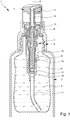
- Fig. 1 shows a schematic section of a proposed dispensing device 1 for dispensing a product or fluid 2. In the state shown, the dispensing device 1 is not actuated or the dispensing device 1 is in an initial or rest position.
- the dispensing device 1 preferably has a container 3 with or for the product 2 and / or a dispensing head 4 for dispensing the product 2 to a user (not shown).
- the dispensing head 4 is preferably connected or connectable to the container 3, in particular mechanically and / or fluidically.
- the dispensing device 1 has a (separate) closure 5, preferably with the dispensing head 4 being connected or connectable to the container 3 via the closure 5 in a form-fitting, non-positive and / or cohesive manner, in particular by screwing.
- the dispensing head 4 has or forms the closure 5 and / or the dispensing head 4 is or can be connected directly or directly to the container 3.
- the container 3 is preferably designed as a reservoir for the product 2.
- the dispensing device 1 or container 3 particularly preferably comprises a volume of more than 5 ml or 10 ml, in particular more than 50 ml or 100 ml, and / or less than 1000 ml or 800 ml, in particular less than 600 ml or 500 ml.
- the container 3 is preferably elongated, cylindrical and / or rigid.
- the container 3 is particularly preferably made of metal, plastic or glass.
- the dispensing device 1 has an optional bag 6, preferably with the bag 6 being arranged in the interior of the container 3 and / or containing the product 2.
- the optional bag 6 is preferably designed to be flexible or elastic.
- the bag 6 is compressible, preferably in such a way that the volume of the bag 6 (correspondingly) decreases with each dispensing of the product 2.
- other solutions are also possible here.
- the dispensing device 1 preferably has a pump 7, in particular of the type mentioned at the beginning.
- the pump 7 is particularly preferably designed as a displacement pump, in particular a metering pump or reciprocating piston pump.
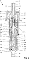
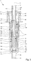
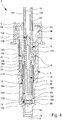
- FIGS. 2 to 4 each show a schematic section of the pump 7 in different states or positions.
- the pump 7 is preferably designed to suck or convey the product 2, in particular a predefined volume of the product 2, from the container 3 or the bag 6, to put it under pressure and / or to dispense it under pressure.
- the dispensing head 4 is particularly preferably fluidly connected or connectable to the container 3 via the pump 7.
- the pump 7 is preferably arranged at least partially in the interior of the container 3. In particular, the pump 7 extends from the dispensing head 4 into the container 3.
- the pump 7 is preferably connected or can be connected to the container 3 and / or dispensing head 4 in a form-fitting, force-fitting and / or material fit.
- the pump 7 is fastened to the container 3 via the closure 5 and the dispensing head 4 is plugged onto the pump 7.
- the pump 7 is integrated into the dispensing head 4 and / or has or forms the closure 5.
- the pump 7 preferably has a pump housing 8, a housing cover 9, an inlet 10, an outlet 11, an inlet valve 12, an outlet valve 13, a pump piston 14, a pump chamber 15 and / or a spring 16.
- the pump housing 8, the housing cover 9, the inlet 10, the outlet 11, the inlet valve 12, the outlet valve 13 and / or the pump piston are preferably / is 14, particularly preferably all parts or components of the pump 7 - except for the spring 16 - made of plastic and / or injection molded.
- the pump 7, in particular the pump housing 8, is preferably elongated and / or rotationally symmetrical.
- the pump 7 or the pump housing 8 has a longitudinal axis A, preferably the longitudinal axis A being an axis of rotation of the pump 7 or the pump housing 8.
- the pump housing 8 is preferably designed as a particularly elongated hollow cylinder.
- the pump 7 can preferably be flowed through axially or along the longitudinal axis A and / or from the inlet 10 to the outlet 11.
- the inlet 10 is preferably arranged on a first end of the pump 7, which is the lower end in the usual position of use of the dispensing device 1, and the outlet 11 is arranged on a second end of the pump 7, which is the upper end of the pump 7 in the usual position of use of the dispensing device 1.
- the inlet 10 and the outlet 11 preferably form the axial ends of the pump 7, in particular with the inlet 10 being assigned to the container 3 and the outlet 11 to the dispensing head 4.
- the product 2 or a predefined volume of the product 2 can preferably be fed to the pump chamber 15 via the inlet 10 and / or can be fed from the pump chamber 15 to the dispensing head 4 via the outlet 11.
- the inlet valve 12 is preferably assigned to the inlet 10 and / or arranged between the inlet 10 and the pump chamber 15.
- the outlet valve 13 is preferably assigned to the outlet 11 and / or is arranged between the outlet 11 and the pump chamber 15.
- the flow through the pump 7 can preferably be controlled by means of the inlet valve 12 and / or the outlet valve 13.
- the inlet valve 12 is preferably designed to allow the product 2 to flow from the container 3 into the pump chamber 15, in particular as a function from the pressure in the pump chamber 15, optionally to enable or prevent.
- the outlet valve 13 is preferably designed to selectively enable or prevent a flow of the product 2 from the pump chamber 15 to the outlet 11, in particular as a function of the pressure in the pump chamber 15, 15.
- the inlet valve 12 and / or the outlet valve 13 are designed as an automatically opening or automatically closing valve, preferably with the inlet valve 12 or the outlet valve 13 opening or closing depending on the pressure in the pump chamber 15.
- the pressure in the pump chamber 15 or the volume of the pump chamber 15 can preferably be changed by actuating the dispensing device 1 or pump 7 or by a stroke movement of the pump piston 14.
- the volume of the pump chamber 15 can be reduced by actuating the dispensing device 1 or moving the pump piston 14 downwards or in the direction of the container 3 and / or the pressure in the pump chamber 15 by actuating the dispensing device 1 or moving the pump piston 14 downwards or in the direction of the container 2 can be increased.
- the outlet valve 13 opens (automatically) when a certain pressure in the pump chamber 15 is exceeded or the pump chamber 15 is reduced by means of the pump piston 14 and / or closes the outlet valve 13 (automatically) when the pressure in the pump chamber 15 or below falls below a certain level. an enlargement of the pump chamber 15 by means of the pump piston 14.
- the inlet valve 12 opens when the pressure in the pump chamber 15 falls below a certain level or the pump chamber 15 is enlarged by means of the pump piston 14 and / or the inlet valve 12 closes (automatically) when a certain pressure in the pump chamber 15 is exceeded or when the pump chamber 15 is reduced the pump chamber 15 by means of the pump piston 14.
- valves 12, 13 can consequently be opened or closed as a function of the movement of the pump piston 14, in particular automatically, preferably whereby the outlet valve 13 and the inlet valve 12 can be opened or closed contrary to one another or can be actuated by the movement of the pump piston 14.
- the inlet valve 12, outlet valve 13, the pump piston 14, the pump chamber 15 and the spring 16 are preferably arranged at least partially in the pump housing 8 or encased by the pump housing 8.
- the inside diameter of the pump housing 8 tapers towards the container 3 or, in the usual position of use, of the dispensing device 1 downwards.
- the pump housing 8 preferably has a first (axial) end 8A, arranged at the bottom in the usual position of use of the dispensing device 1, and a second (axial) end 8B arranged at the top in the usual position of use of the dispensing device 1, preferably with the first end 8A and the second end 8B each have or form an (axial) opening of the pump housing 8.
- the pump housing 8 preferably the first end 8A, has or forms the inlet 10 and / or the pump housing 8 tapers in the direction of the container 3 to the inlet 10.
- the inner diameter of the inlet 10 or of the first end 8A is particularly preferably smaller than the inner diameter of the second end 8B.
- the inlet 10 is preferably designed as a connection or nipple for an optional riser pipe 17.
- the inlet 10 is preferably designed as a connection or nipple for an optional riser pipe 17.
- other solutions are also possible here.
- the (inner) components of the pump 7, such as the spring 16 or the pump piston 14, are preferably introduced or mounted into the pump housing 8 via the second end 8B.
- the housing cover 9 preferably closes the pump housing 8, in particular the second end 8B, particularly preferably axially.
- the housing cover 9 and the pump housing 8 are preferably connected to one another in a form-fitting, force-fitting and / or material fit.
- the housing cover 9 is plugged or latched onto the pump housing 8, in particular the second end 8B, and / or designed as a cap.
- the pump housing 8 preferably has a preferably circumferential (radial) projection or flange 8C, preferably with the projection or flange 8C in the housing cover 9, in particular in a recess or groove 9A corresponding to the projection or flange 8C of the housing cover 9 is engaged.
- the pump piston 14 is preferably elongated and / or preferably has an in particular elongated piston shaft 14A and / or a piston head 14B — in particular enlarged in comparison to the piston shaft 14A.
- the pump piston 14, in particular the piston shaft 14A, preferably protrudes from the pump housing 8 or the housing cover 9.
- the housing cover 9 particularly preferably has an (axial) opening 9B, preferably wherein the pump piston 14, in particular the piston shaft 14A, extends through the opening 9B of the housing cover 9 to the outside or towards the dispensing head 4.
- the pump piston 14 or piston shaft 14A has an (axial) outlet channel 14C, preferably wherein the outlet channel 14C opens into the outlet 11.
- the dispensing head 4 is preferably connected or connectable to the pump 7 in a form-fitting, force-fitting and / or material fit.
- the dispensing head 4 is plugged onto the pump 7, in particular the pump piston 14 or the piston shaft 14A.
- other solutions are also possible here.
- the pump piston 14 is preferably movable axially or along the longitudinal axis A, in particular in order to suck in the product 2 from the container 3 or to enlarge the pump chamber 15, to pressurize the sucked in product 2 in the pump chamber 15 or to close the pump chamber 15 and dispense via the outlet channel 14C or the outlet 11, in particular to or via the dispensing head 4.
- the pump piston 14 is preferably designed to execute a stroke movement in or relative to the pump housing 8.
- the pump piston 14 can be moved downwards or in the direction of the container 3 or inlet 10 by actuating or pressing down the dispensing head 4, in particular to reduce the size of the pump chamber 15 or to put the product 2 in the pump chamber 15 under pressure.
- the piston head 14B preferably has a larger diameter than the piston shaft 14A and / or the pump piston 14 is guided laterally or radially over the piston head 14B in the pump housing 8.
- the pump piston 14 or the piston head 14B preferably has a particularly circumferential guide surface 14D, preferably the guide surface 14D being in contact with the inner surface 8E of the pump housing 8 or being slidably movable over the inner surface 8E of the pump housing 8.
- the pump piston 14 or the piston head 14B preferably has an in particular circumferential seal 14E, preferably the seal 14E being in contact with the inner surface 8E of the pump housing 8, in particular such that the pump chamber 15 is sealed to the outside or axially or to the top .
- the seal 14E is preferably designed in one piece with the pump piston 14 or the pump piston 14, in particular the piston head 14B, forms the seal 14E.
- the seal 14E is designed as a piston ring and / or is embedded in a circumferential groove on the piston head 14B.
- the pump 7 preferably has at least one spring 16, in particular the spring 16 being designed as a helical spring and / or made of metal.
- the spring 16 is preferably arranged completely in the pump housing 8.
- the spring 16 is arranged at least substantially centrally in the pump housing 8 and / or coaxially to the pump housing 8 and / or the pump piston 14.
- the spring 16 is arranged eccentrically in the pump housing 8 and / or radially offset from the longitudinal axis A of the pump housing 8 or of the pump piston 14.
- the spring 16 is preferably counter-supported axially in the pump housing 8, in particular at the first end 8A of the pump housing 8, as will be explained in more detail below.
- the spring 16 is preferably compressible or compressible by actuating the dispensing head 4 or moving the pump piston 14 downward or in the direction of the inlet 10.
- the pump piston 14 is preferably pretensioned by means of the spring 16 and / or can be moved downward against the spring force of the spring 16 or in the direction of the spring 16, in particular to reduce the volume of the pump chamber 15 or the product 2 in the pump chamber 15 under pressure to be set and / or to be supplied from the pump chamber 15 via the outlet channel 14C to the outlet 11.
- the exact sequence of the pumping or lifting movement of the pump piston 14 is explained in greater detail below with reference to FIGS. 2 to 4 explained.
- An essential aspect of the present invention is to separate the spring 16 from the product 2 or to prevent (direct) contact between the spring 16 and the product 2, in particular independently of a pumping or lifting movement of the pump piston 14.
- the dispensing device 1 or the pump 7 has (for this) a - in particular removable - spring sleeve or capsule 18, with the spring 16 being arranged in the spring sleeve or capsule 18 and / or with the spring sleeve or capsule 18 the spring 16 separates and / or surrounds the product 2 or the pump chamber 15 or is arranged around the spring 16.
- the dispensing device 1 or the pump 7 has a preferably closed or sealed spring chamber 19, preferably wherein the spring 16 is arranged (completely) in the spring chamber 19 and / or the spring sleeve 18 has the spring chamber 19, forms or, in particular, radially and axially - limited.
- the spring sleeve 18 is preferably designed as a particularly closed or sealed housing and / or at least essentially rigid.
- the spring sleeve 18 is made or injection molded from plastic.
- the spring sleeve 18 or the spring chamber 19 is preferably elongated and / or cylindrical. Particularly preferably, the inner diameter of the spring sleeve 18 or the spring chamber 19 corresponds at least essentially to the outer diameter of the spring 16.
- the spring sleeve 18 or the spring chamber 19 is preferably filled with a compressible medium, in particular gas, particularly preferably air.
- the spring sleeve 18 or spring chamber 19 is preferably arranged centrally in the pump housing 8 and / or coaxially with the pump housing 8 or the pump piston 14.
- the pump chamber 15 extends - particularly preferably in the form of a ring - around the spring sleeve 18 or the spring chamber 19, in particular in such a way that the spring sleeve 18 or the spring chamber 19 can be flowed around.
- the pump chamber 15 is delimited laterally or radially by the spring sleeve 18 and by the pump housing 8 and / or the spring sleeve 18 forms an inner wall and the pump housing 8 forms an outer wall of the pump chamber 15.
- the pump housing 8 preferably has a receptacle 8F for - in particular radially and / or axially - receiving the spring sleeve 18, preferably wherein the receptacle 8F is arranged between the inlet 10 or the inlet valve 12 on the one hand and the pump chamber 15 or the pump piston 14 on the other .
- the pump chamber 15 preferably tapers in the direction of the container 3 or downwards to the receptacle 8F or the pump chamber 15 has a larger diameter than the receptacle 8F.
- the inner diameter of the receptacle 8F preferably corresponds at least essentially to the outer diameter of the spring sleeve 18 or the lower part of the spring sleeve 18, in particular such that the spring sleeve 18 is seated firmly or at least essentially free of play in the receptacle 8F of the pump housing 8.
- the spring sleeve 18 preferably protrudes from the receptacle 8F into the pump chamber 15 and / or the spring sleeve 18 extends from the receptacle 8F into the pump chamber 15.
- the spring sleeve 18 preferably has - at least at the end or in the region of the receptacle 8F - several, in particular elongated or rib-like projections 18A, preferably the projections 18A each extending parallel to the longitudinal axis A on the outside of the spring sleeve 18.
- the spring sleeve 18 preferably has, in particular at the end or in the region of the receptacle 8F, several guide channels 18B, preferably the guide channels 18B being formed by the projections 18A or laterally delimited by the projections 18A.
- the guide channels 18B fluidically connect the pump chamber 15 to the inlet 10 or inlet valve 12. In this way, the product 2 can flow from the inlet valve 12 into the pump chamber 15.
- the pump housing 8 or the receptacle 8F has projections and / or depressions in order to enable the product 2 to flow from the inlet valve 12 to the pump chamber 15.
- the bearing 8G is preferably formed by a step or rib-like projections - in particular around the inlet valve 12.
- the inlet valve 12 is preferably arranged between the pump chamber 15 and the inlet 10.
- the inlet valve 12 is particularly preferably arranged between the lower end of the spring sleeve 18 or the end assigned to the inlet 10 and the inlet 10.
- the inlet valve 12 preferably has a valve seat 12A and a valve body 12B, preferably wherein the valve body 12B can be moved relative to the valve seat 12A, in particular in order to open and close the inlet valve 12.
- the valve seat 12A is preferably formed by the pump housing 8, in particular by a step 8D of the pump housing 8.
- the valve body 12B can preferably be raised from the valve seat 12A, in particular when the pump chamber 15 is enlarged or the pressure in the pump chamber 15 is reduced, in particular in such a way that the inlet valve 12 opens.
- the valve body 12B can preferably be lowered onto the valve seat 12A, in particular when the pump chamber 15 is reduced in size or the pressure in the pump chamber 15 increases, particularly preferably in such a way that the inlet valve 12 closes.
- the spring sleeve 18 preferably has a limitation or a stop 18C or the spring sleeve 18 forms a limitation or a stop 18C for the inlet valve 12, in particular the valve body 12B.
- the limitation 18C is preferably designed to limit or restrict the movement of the valve body 12B.
- the delimitation 18C is particularly preferably formed by one or more — in particular axial — projections of the spring sleeve 18.
- the delimitation 18C is designed like a crown and / or the delimitation 18C preferably has a plurality of axial prongs or projections, preferably the teeth or projections pointing in the direction of the inlet valve 12 or valve body 12B.
- the prongs or projections reduce the delimitation surface or support surface for the valve body 12B, so that the valve body 12B is prevented from sticking to the delimitation 18C.
- the valve body 12B of the inlet valve 12 is preferably designed as a movable plate, preferably wherein the valve body 12B rises or falls as a function of the pressure in the pump chamber 15.
- the inlet valve 12 opens by lifting the valve body 12B from the valve seat 12A in the direction of the spring sleeve 18 or the limitation 18C, in particular when the pressure in the pump chamber 15 falls and / or the pump piston 14 moves upwards.
- the inlet valve 12 is designed as a diaphragm valve or the valve body 12B is designed as a particularly flexible diaphragm, preferably with the spring sleeve 18, in particular the delimitation 18C, preferably holding or clamping the valve body 12B axially and / or the inlet valve 12 can be opened by, in particular, deforming or lifting the valve body 12B at the edge.
- the spring sleeve 18 is preferably constructed in several parts and / or formed by several (separate) components or parts.
- the spring sleeve 18 has a base part 20 and a head part 21, preferably with the base part 20 in the usual position of use of the dispensing device 1 at the bottom or in the receptacle 8F and the head part 21 in the usual position of use of the dispensing device 1 at the top or in the pump chamber 15 .
- the base part 20 preferably forms a lower end of the spring sleeve 18 that faces the inlet 10, and the head part 21 forms an upper end of the spring sleeve 18 that faces the outlet 11.
- the base part 20 and the head part 2 completely or completely close the spring chamber 19. both axially and radially.
- the base part 20 is preferably designed to receive a first, in the usual position of use of the dispensing device 1, the lower end 16A of the spring 16 and the head part 21 to receive a second, in the usual position of use of the dispensing device, the upper end 16B of the spring 16.
- the spring sleeve 18 is preferably designed telescopically.
- the spring sleeve 18 or the spring chamber 19 can be compressed or compressed.
- the base part 20 and the head part 21 are preferably movable or displaceable relative to one another, in particular in order to enlarge or reduce the spring chamber 19.
- the base part 20 is immovable or fixed in the receptacle 8F relative to the pump housing 8 and / or the head part 21 is (axially) movable relative to the pump housing 8 or base part 20 and / or in the pump chamber 15.
- the spring sleeve 18 or the base part 20 and / or the head part 21 is / are at least substantially rigid.
- the spring sleeve 18 is designed to be elastically deformable.
- the spring sleeve 18 can be made of an elastic, compressible and / or foldable material in order to enable a stroke movement of the pump piston 14.
- the base part 20 and the head part 21 are preferably plugged into one another and / or the base part 20 and the head part 21 overlap, in particular in the area of the pump chamber 15.
- the head part 21 is preferably plugged onto the base part 20 or extends Base part 20 in the head part 27.
- other solutions are also possible, in particular in which the head part 21 is inserted into the base part 20.
- the spring sleeve 18, in particular the base part 20 and / or the head part 21, preferably has a guide or bearing pin 18D, preferably wherein the pin 18D protrudes axially into the spring chamber 19 and / or is designed to support the spring 16 or the second end 16B of the spring 16 to hold or to guide.
- the pin 18D is designed to stabilize the spring 16 and / or to prevent the spring 16 from buckling when the spring 16 or the spring sleeve 18 is compressed.
- the outer diameter of the head part 21 is preferably smaller than the inner diameter of the pump chamber 15, in particular such that a gap (through which a flow can flow) is formed between the head part 21 and the pump housing 8.
- a gap through which a flow can flow
- the head part 21 and / or the pump housing 8 preferably have / has rib-like projections and / or elongated depressions in order to allow the product 2 to flow through the pump chamber 15 or from the inlet 10 to the outlet 11 to enable.
- the head part 21 preferably has an in particular circumferential seal or sealing lip 21A for sealing the spring sleeve 18 or spring chamber 19.
- the seal 21A is designed to seal the spring chamber 19 with respect to the pump chamber 15.
- the seal 21A preferably rests radially on the base part 20, in particular in such a way that the seal 21A is pressed (further) against the base part 20 by an increase in pressure in the pump chamber 15. This ensures that the spring chamber 19 is sealed in spite of a pressure increase in the pump chamber 15.
- the pump 7 preferably has a connecting element 22, preferably the connecting element 22 connecting the pump piston 14 (mechanically) to the spring 16 or the spring sleeve 18, in particular the head part 21.
- the connecting element 22 is preferably elongated and / or preferably extends from the outlet valve 13 into the pump chamber 15.
- the connecting element 22 and the pump piston 14 preferably form the outlet valve 13, in particular the pump piston 14 having or forming the valve seat 13A and the connecting element 22 having or forming the valve body 13B of the outlet valve 13.
- the connecting element 22 tapers upwards or in the direction of the dispensing head 4 to the valve body 13B and / or the connecting element 22 has a conical or conical end which has or forms the valve body 13B or a valve cone as valve body 13B.
- the connecting element 22 and the spring sleeve 18, in particular the head part 21, are preferably firmly, preferably positively and / or non-positively connected to one another.
- the connecting element 22 and the head part 21 are designed as separate components.
- solutions are also possible here in which the head part 21 and the connecting element 22 are formed in one piece or form a structural unit.
- the connecting element 22 is preferably made of plastic or is injection molded.
- the connecting element 22 preferably extends into the spring sleeve 18 or through the head part 21 into the spring chamber 19.
- the connecting element 22 has the pin 18D and / or forms the connecting element 22, in particular a lower, the end of the connecting element 22 associated with the spring sleeve 18, the pin 18D.
- the head part 21 has or forms the pin 18D.
- the connecting element 22 is preferably movable downward relative to the pump piston 14 or in the usual position of use of the dispensing device 1, preferably around the outlet valve 13, in particular after a predetermined pressure in the pump chamber 15 is exceeded or by actuating the dispensing device 1 or the dispensing head 4 open or lift the valve body 13B from the valve seat 13A and / or feed the product 2 from the pump chamber 15 to the outlet 11.
- the connecting element 22 and the head part 21 can be moved together against the spring force of the spring 16 in order to open the outlet valve 13 and enable the product 2 to be dispensed from the pump chamber 14.
- Fig. 1 shows the dispensing device 1 or the pump 7 in the non-actuated state or in a starting position.
- Fig. 2 shows the pump 7 during actuation or during the delivery of the product 2.
- Fig. 3 shows the pump 7 in an end position in which the pump piston 14 or the connecting element 22 is moved completely downwards or in the direction of the inlet 10.
- Fig. 4 shows the pump 7 when the pump piston 14 is returned to the starting position or during the suction or filling of the pump chamber 5 with the product 2.
- the starting or rest position of the dispensing device 1 or the pump 7 is preferably that position that the pump 7, in particular the pump piston 14 or the head part 21 or the connecting element 22, in the non-actuated state and / or automatically or by the The spring force of the spring 16 assumes.
- the volume of the pump chamber 15 is maximum and / or the spring 16 presses the pump piston 14, the head part 21 and / or the connecting element 22 upwards or against the pump housing 8 or the housing cover 9.
- the starting position or a movement of the pump piston 14 beyond the starting position is preferably limited by the stop of the pump piston 14, in particular the piston head 14B, against the pump housing 8 or the housing cover 9 (axially or upwards).
- the end position is preferably that position which the pump 7, in particular the pump piston 14 or the head part 21 or the connecting element 22, assumes when the pump 7 is fully actuated.
- the pump piston 14 or the head part 21 or the connecting element 22 is moved or pressed completely downwards or in the direction of the inlet 10 in the end position.
- the volume of the pump chamber 15 is minimal and / or smaller than in the starting position.
- the end position or a movement of the pump piston 14 beyond the end position is preferably limited by the stop of the connecting element 22 or the head part 21 against the base part 20 and / or the pump housing 8 (axially or downwards).
- the pump 7 is preferably removed from the starting position by (manually) actuating or depressing the dispensing head 4, as in FIG Fig. 1 shown in the end position, as in Fig. 3 shown, transferable.
- the spring 16 is preferably designed to transfer the pump 7, in particular by means of spring force or automatically, from the end position to the starting position. In particular, the spring 16 automatically resets the pump 7 or the pump piston 14 to the starting position after the pump 7 has been actuated.
- the pump piston 14 or the connecting element 22 or the head part 21 are or is preferably prestressed in the starting position by means of the spring 16.
- the spring 16 presses the head part 21 or the connecting element 22 or the pump piston 14 against the pump housing 8 or the housing cover 9.
- the pump piston 14, in particular together with the head part 21 or the connecting element 22, can be moved against the spring force of the spring 16 or, in the usual position of use, downwards or in the direction of the container 3, preferably whereby the volume of the pump chamber 15 is reduced and / or the pressure in the pump chamber 15 is increased, as already explained.
- the inlet valve 12 is (automatically) closed and / or the valve body 12B is pressed against the valve seat 12A, in particular in such a way that the product 2 in the pump chamber 15 does not return can flow into the container 3.
- the head part 21 is preferably moved relative to the base part 20 and / or the spring chamber 19 is reduced in size and / or the gas pressure in the spring chamber 19 is increased.
- the spring sleeve 16 or the spring chamber 19 is preferably designed in such a way that no gas or no air escapes from the spring chamber 19 into the pump chamber 15, even with or despite an increase in pressure due to compression of the spring chamber 19.
- the outlet valve 13 is designed to open automatically when a predetermined pressure in the pump chamber 15 is exceeded.
- an increase in pressure in the pump chamber 15 or an actuation of the dispensing device 1 or the dispensing head 4 or the pump 7 causes the valve body 13B or the connecting element 22 to move relative to the valve seat 13A or to the pump piston 14 or away from it
- Valve seat 13A or pump piston 14 lifts off, preferably in such a way that outlet valve 13 opens and / or product 2 can flow from pump chamber 15 through outlet valve 13 into outlet channel 14C of pump piston 14, as in FIG Fig. 2 indicated by arrows.
- the opening of the outlet valve 13 causes a pressure drop in the pump chamber 15, preferably such that the outlet valve 13 would close again without further actuation of the dispensing device 1.
- the volume of the pump chamber 15 is further reduced or the product 2 in the pump chamber 15 is pressurized, preferably in such a way that the outlet valve 13 remains open for as long until the end position, as in Fig. 3 shown, is achieved.
- the dispensing process is completed and / or the outlet valve 13 closes, in particular in that the pump housing 8 and / or the base part 20 press the valve body 13B or the connecting element 22 or the head part 21 against the valve seat 13A or . the pump piston 14 presses.
- the pump chamber 15 is preferably filled automatically.
- the spring 16 pushes the pump piston 14 or the head part 21 or the connecting element 22 again upwards or in the direction of the dispensing head 4 or into the starting position.
- the volume of the pump chamber 15 is increased and / or the pressure is reduced by increasing the volume of the pump chamber 15, preferably thereby the inlet valve 12 opens or the valve body 12B is lifted from the valve seat 12A, as in FIG Fig. 4 shown.
- the volume of the spring chamber 19 also increases and / or the head part 21 moves relative to the base part 20 or upwards.
- the product 2 flows when the pump piston 14 is returned to the starting position through the inlet valve 12 laterally past the spring sleeve 18 into the pump chamber 15, in particular without coming into (direct) contact with the spring 16.
- the outlet valve 13 is or remains closed during the (entire) movement of the pump piston 14 upwards or into the starting position.
- the filling of the pump chamber 15 is complete.
- the product 2 located in the pump chamber 15 can then be dispensed, as already explained.
- the proposed dispensing device 1 or pump 7 enables the spring 16 - in particular independently of a pumping or lifting movement of the pump 7 - to be separated from the product 2 and / or the spring chamber 19 - in particular independent of a pumping or lifting movement of the Pump 7 - is sealed.
Landscapes
- Reciprocating Pumps (AREA)
- Containers And Packaging Bodies Having A Special Means To Remove Contents (AREA)
- Closures For Containers (AREA)
Description
- Die vorliegende Erfindung betrifft eine Pumpe gemäß dem Oberbegriff des Anspruchs 1 sowie eine Abgabevorrichtung gemäß dem Oberbegriff des Anspruchs 15.
- Unter dem Begriff "Abgabevorrichtung" ist bei der vorliegenden Erfindung vorzugsweise eine Vorrichtung zur insbesondere sprühenden Aus- bzw. Abgabe eines vorzugsweise flüssigen Produkts, besonders bevorzugt als Aerosol, zu verstehen.
- Vorzugsweise umfasst eine Abgabevorrichtung im Sinne der vorliegenden Erfindung einen Behälter als Reservoir mit einem bzw. für ein Produkt, eine Pumpe zum Fördern des Produkts und einen Abgabekopf zur insbesondere sprühenden Abgabe des Produkts an einen Nutzer. Vorzugsweise ist eine Abgabevorrichtung im Sinne der vorliegenden Erfindung manuell betätigbar bzw. weist eine Abgabevorrichtung im Sinne der vorliegenden Erfindung eine manuelle bzw. handbetätigbare Pumpe auf.
- Unter dem Begriff "Pumpe" ist bei der vorliegenden Erfindung vorzugsweise eine konstruktive Einrichtung zu verstehen, die zur Förderung eines Produkts, insbesondere eines Fluids, ausgebildet ist. Insbesondere ist mittels einer Pumpe ein Produkt aus einem Behälter ansaugbar, unter Druck setzbar und/oder beispielsweise als Aerosol abgebbar. Vorzugsweise ist eine Pumpe im Sinne der vorliegenden Erfindung als insbesondere handbetätigbare Verdrängerpumpe, insbesondere Dosierpumpe, besonders bevorzugt Hubkolbenpumpe, ausgebildet, insbesondere wobei durch (manuelle) Betätigung der Pumpe, insbesondere pro Hub, ein definiertes Volumen des Produkts gefördert wird bzw. förderbar ist.
- Vorzugsweise weist eine Pumpe im Sinne der vorliegenden Erfindung einen Pumpenkolben, eine Pumpenkammer, einen Einlass und einen Auslass auf, vorzugsweise wobei der Einlass und der Auslass jeweils durch ein zugeordnetes Ventil öffenbar bzw. verschließbar sind. Insbesondere ist ein definiertes Volumen eines Produkts durch eine Hub-Bewegung des Pumpenkolbens in die Pumpenkammer förderbar bzw. ansaugbar, in der Pumpenkammer unter Druck setzbar und aus der Pumpenkammer über den Einlass abgebbar.
- Unter dem Begriff "Produkt" sind im Sinne der vorliegenden Erfindung insbesondere Fluide, wie Flüssigkeiten, Suspensionen o. dgl., zu verstehen. Ein Produkt im Sinne der vorliegenden Erfindung ist beispielsweise als Paste, Strahl oder Nebel bzw. Aerosol oder in sonstiger Weise, beispielsweise als Schaum oder Gel, abgebbar.
- Die
DE 103 35 842 B4 offenbart eine Abgabevorrichtung der eingangs erwähnten Art, wobei die Abgabevorrichtung eine Pumpe, einen Behälter und einen Abgabekopf aufweist. Die Pumpe weist ein Pumpengehäuse, eine Pumpenkammer, einen Pumpenkolben, ein Einlassventil und ein Auslassventil auf. Bei Betätigung der Abgabevorrichtung wird der Pumpenkolben nach unten bzw. gegen die Federkraft einer im Pumpengehäuse angeordneten Feder derart gedrückt, dass sich das Volumen der Pumpenkammer verkleinert und somit das Produkt in der Pumpenkammer unter Druck gesetzt wird. Durch die Drückerhöhung in der Pumpenkammer öffnet sich das Auslassventil, so dass das unter Druck gesetzte Produkt über den Abgabekopf an einen Nutzer abgegeben wird. - Auch die
US 2013/0112766 A1 ,US 4,154,374 A undEP 0 484 835 A1 offenbaren jeweils eine Abgabevorrichtung der eingangs erwähnten Art, wobei die Abgabevorrichtung eine Pumpe mit einem bewegbaren Pumpenkolben aufweist, um ein Produkt aus einem Behältnis zu fördern. - Der Erfindung liegt die Aufgabe zugrunde, eine verbesserte Abgabevorrichtung sowie eine verbesserte Pumpe für eine Abgabevorrichtung anzugeben, insbesondere wobei bzw. wodurch ein einfacher, stabiler, kompakter und/oder kostengünstiger Aufbau und/oder eine hygienische Förderung bzw. Abgabe des Produkts ermöglicht oder unterstützt werden/wird und/oder die Strömungsführung in der Pumpe verbessert wird.
- Die obige Aufgabe wird durch eine Pumpe gemäß Anspruch 1 oder eine Abgabevorrichtung gemäß Anspruch 15 gelöst. Vorteilhafte Weiterbildungen sind Gegenstand der Unteransprüche.
- Die vorschlagsgemäße Pumpe weist vorzugsweise ein Pumpengehäuse, einen Pumpenkolben, eine Pumpenkammer und eine - insbesondere metallische - Feder auf, vorzugsweise wobei der Pumpenkolben mittels der Feder in eine Ausgangsposition vorgespannt bzw. gegen die Federkraft der Feder bewegbar ist, insbesondere um das Produkt bzw. ein vordefiniertes Volumen des Produkts in der Pumpenkammer unter Druck zu setzen bzw. das Volumen der Pumpenkammer zu verkleinern.
- Ein Aspekt der vorliegenden Erfindung liegt darin, dass die Pumpe eine - vorzugsweise zylindrische und/oder aus dem Pumpengehäuse herausnehmbare bzw. separate - Federhülse bzw. -kapsel - vorzugsweise um die Feder - aufweist, wobei die Federhülse bzw. -kapsel die Feder insbesondere vollständig ummantelt und/oder vom Produkt trennt, insbesondere derart, dass die Feder - insbesondere unabhängig von einer Pump- bzw. Hubbewegung des Pumpenkolbens - nicht in Kontakt mit dem Produkt gelangt. Besonders bevorzugt ist die Federhülse bzw. - kapsel als Korrosionsschutz für die Feder ausgebildet.
- Vorzugsweise erstreckt sich die Pumpenkammer - insbesondere ringartig - um die Federhülse und/oder ist die Pumpenkammer seitlich von der Federhülse und dem Pumpengehäuse begrenzt, vorzugsweise derart, dass das Produkt um die Feder herum vorbeigeführt wird bzw. vorbeiführbar ist.
- Durch eine derartige Konstruktionsweise wird der unmittelbare Kontakt der Feder mit dem Produkt bzw. eine mögliche Reaktion des Federmaterials mit dem Produkt vermieden. Insbesondere wird die Korrosionsgefahr der Feder reduziert und/oder verhindert, dass die Feder korrodiert bzw. rostet und (somit) die Produktqualität beeinträchtigt.
- Darüber hinaus können die Anforderungen an die Materialqualität der Feder reduziert werden. Insbesondere ist es durch die Federhülse nicht mehr notwendig, die Oberfläche der Feder zum Schutz vor Korrosion zu behandeln. Auf diese Weise wird ein besonders kostengünstiger Aufbau der Pumpe ermöglicht bzw. unterstützt.
- Zusätzlich verhindert eine derartige Konstruktionsweise, dass die Feder einen (direkten) Strömungswiderstand für das Produkt bildet. Insbesondere werden etwaige Turbulenzen bzw. Strömungsverluste, die bei unmittelbaren Kontakt zwischen der Feder und dem Produkt entstehen, reduziert. Die Federhülse ermöglicht folglich eine besonders einfache bzw. verlustarme Strömungsführung in der Pumpe, vorzugsweise ohne starke Umlenkungen, beispielsweise von mehr als 90° oder 120°. Auf diese Weise wird die Effizienz der Pumpe erhöht.
- Gemäß einem weiteren, auch unabhängig realisierbaren Aspekt der vorliegenden Erfindung weist die Pumpe eine abgedichtete bzw. geschlossene Federkammer zur Aufnahme bzw. Lagerung der Feder auf, vorzugsweise wobei die Feder in der Federkammer angeordnet ist und/oder die Federkammer unabhängig von einer Hubbewegung abgedichtet bzw. geschlossen ist, insbesondere derart, dass die Federkammer von dem Produkt nicht durchströmt wird bzw. durchströmbar ist. Besonders bevorzugt ist die Federkammer mit einem Gas, insbesondere Luft, gefüllt. Auf diese Weise werden entsprechende Vorteile realisiert.
- Vorzugsweise ist die Federkammer durch die Federhülse gebildet bzw. nach außen bzw. zur Pumpenkammer begrenzt.
- Vorzugsweise ist die Federhülse mehrteilig und/oder teleskopisch bzw. zusammendrückbar ausgebildet, insbesondere derart, dass die Federkammer bzw. die Feder in der Federkammer komprimierbar bzw. zusammendrückbar ist. Auf diese Weise ist es möglich, die Feder unabhängig von einer Hubbewegung der Pumpe bzw. des Pumpenkolbens von dem Produkt zu trennen.
- Die vorschlagsgemäße Abgabevorrichtung weist vorzugsweise einen Behälter, einen Abgabekopf und eine derartige Pumpe auf. Auf diese Weise werden entsprechende Vorteile realisiert.
- Die oben genannten Aspekte und Merkmale der vorliegenden Erfindung sowie die sich aus den Ansprüchen und der nachfolgenden Beschreibung ergebenden Aspekte und Merkmale der vorliegenden Erfindung können grundsätzlich unabhängig voneinander, aber auch in beliebiger Kombination realisiert werden.
- Weitere Aspekte, Vorteile, Merkmale und Eigenschaften der vorliegenden Erfindung ergeben sich aus den Ansprüchen und der nachfolgenden Beschreibung einer bevorzugten Ausführungsform anhand der Zeichnung. Es zeigt:
- Fig. 1
- einen schematischen Schnitt einer vorschlagsgemäßen Abgabevorrichtung mit einer vorschlagsgemäßen Pumpe in einer Ausgangsposition;
- Fig. 2
- einen schematischen Schnitt der Pumpe gemäß
Fig. 1 bei der Abgabe eines Produkts; - Fig. 3
- einen schematischen Schnitt der Pumpe gemäß
Fig. 1 in einer Endposition; und - Fig. 4
- einen schematischen Schnitt der Pumpe gemäß
Fig. 1 beim Ansaugen des Produkts. - In den teilweise nicht maßstabsgerechten, nur schematischen Figuren werden für gleiche, gleichartige oder ähnliche Bauteile und Komponenten dieselben Bezugszeichen verwendet, wobei entsprechende oder vergleichbare Eigenschaften und Vorteile erreicht werden, auch wenn von einer wiederholten Beschreibung abgesehen wird.
-
Fig. 1 zeigt einen schematischen Schnitt einer vorschlagsgemäßen Abgabevorrichtung 1 zur Abgabe eines Produkts bzw. Fluids 2. Im dargestellten Zustand ist die Abgabevorrichtung 1 unbetätigt bzw. befindet sich die Abgabevorrichtung 1 in einer Ausgangs- bzw. Ruheposition. - Die Abgabevorrichtung 1 weist vorzugsweise einen Behälter 3 mit dem bzw. für das Produkt 2 und/oder einen Abgabekopf 4 zur Abgabe des Produkts 2 an einen Nutzer (nicht dargestellt) auf.
- Vorzugsweise ist der Abgabekopf 4 - insbesondere mechanisch und/oder fluidisch - mit dem Behälter 3 verbunden oder verbindbar.
- Bei der dargestellten Ausführungsform weist die Abgabevorrichtung 1 einen (separaten) Verschluss 5 auf, vorzugsweise wobei der Abgabekopf 4 form-, kraft- und/oder stoffschlüssig, insbesondere durch Verschrauben, über den Verschluss 5 mit dem Behälter 3 verbunden oder verbindbar ist. Es sind jedoch auch Lösungen möglich, bei denen der Abgabekopf 4 den Verschluss 5 aufweist oder bildet und/oder der Abgabekopf 4 unmittelbar bzw. direkt mit dem Behälter 3 verbunden oder verbindbar ist.
- Vorzugsweise ist der Behälter 3 als Reservoir für das Produkt 2 ausgebildet. Besonders bevorzugt umfasst die Abgabevorrichtung 1 bzw. Behälter 3 ein Volumen von mehr als 5 ml oder 10 ml, insbesondere mehr als 50 ml oder 100 ml, und/oder weniger als 1000 ml oder 800 ml, insbesondere weniger als 600 ml oder 500 ml.
- Der Behälter 3 ist vorzugsweise länglich, zylindrisch und/oder starr ausgebildet. Besonders bevorzugt ist der Behälter 3 aus Metall, Kunststoff oder Glas hergestellt.
- Bei der dargestellten Ausführungsform weist die Abgabevorrichtung 1 einen optionalen Beutel 6 auf, vorzugsweise wobei der Beutel 6 im Inneren des Behälters 3 angeordnet ist und/oder das Produkt 2 enthält.
- Der optionale Beutel 6 ist vorzugweise flexibel bzw. elastisch ausgebildet ist. Insbesondere ist der Beutel 6 komprimierbar, vorzugsweise derart, dass sich das Volumen des Beutels 6 (entsprechend) mit der bzw. jeder Abgabe des Produkts 2 verringert. Hier sind jedoch auch andere Lösungen möglich.
- Die Abgabevorrichtung 1 weist vorzugsweise eine Pumpe 7, insbesondere der eingangs genannten Art, auf. Besonders bevorzugt ist die Pumpe 7 als Verdrängerpumpe, insbesondere Dosierpumpe bzw. Hubkolbenpumpe, ausgebildet.
-
Fig. 2 bis Fig. 4 zeigen jeweils einen schematischen Schnitt der Pumpe 7 in verschiedenen Zuständen bzw. Positionen. - Die Pumpe 7 ist vorzugsweise dazu ausgebildet, das Produkt 2, insbesondere ein vordefiniertes Volumen des Produkts 2, aus dem Behälter 3 bzw. dem Beutel 6 zu saugen bzw. zu fördern, unter Druck zu setzen und/oder unter Druck abzugeben.
- Besonders bevorzugt ist der Abgabekopf 4 über die Pumpe 7 fluidisch mit dem Behälter 3 verbunden oder verbindbar.
- Die Pumpe 7 ist vorzugsweise zumindest teilweise im Inneren des Behälters 3 angeordnet. Insbesondere erstreckt sich die Pumpe 7 vom Abgabekopf 4 bis in den Behälter 3.
- Vorzugsweise ist die Pumpe 7 form-, kraft- und/oder stoffschlüssig mit dem Behälter 3 und/oder Abgabekopf 4 verbunden oder verbindbar.
- Bei der dargestellten Ausführungsform ist die Pumpe 7 über den Verschluss 5 an dem Behälter 3 befestigt und der Abgabekopf 4 auf die Pumpe 7 gesteckt. Hier sind jedoch auch andere Lösungen möglich, beispielsweise bei denen die Pumpe 7 in den Abgabekopf 4 integriert ist und/oder den Verschluss 5 aufweist oder bildet.
- Die Pumpe 7 weist vorzugsweise ein Pumpengehäuse 8, einen Gehäusedeckel 9, einen Einlass 10, einen Auslass 11, ein Einlassventil 12, ein Auslassventil 13, einen Pumpenkolben 14, eine Pumpenkammer 15 und/oder ein Feder 16 auf.
- Vorzugsweise sind/ist das Pumpengehäuse 8, der Gehäusedeckel 9, der Einlass 10, der Auslass 11, das Einlassventil 12, das Auslassventil 13 und/oder der Pumpenkolben 14, besonders bevorzugt alle Bauteile bzw. Komponenten der Pumpe 7 - bis auf die Feder 16 - aus Kunststoff hergestellt und/oder spritzgegossen.
- Die Pumpe 7, insbesondere das Pumpengehäuse 8, ist vorzugsweise länglich und/oder rotationssymmetrisch ausgebildet. Insbesondere weist die Pumpe 7 bzw. das Pumpengehäuse 8 eine Längsachse A auf, vorzugsweise wobei die Längsachse A eine Rotationsachse der Pumpe 7 bzw. des Pumpengehäuses 8 ist.
- Das Pumpengehäuse 8 ist vorzugsweise als insbesondere länglicher Hohlzylinder ausgebildet.
- Vorzugsweise ist die Pumpe 7 axial bzw. entlang der Längsachse A und/oder vom Einlass 10 zum Auslass 11 durchströmbar.
- Vorzugsweise ist der Einlass 10 an einem ersten, in üblicher Gebrauchslage der Abgabevorrichtung 1 unteren Ende der Pumpe 7 und der Auslass 11 an einem zweiten, in üblicher Gebrauchslage der Abgabevorrichtung 1 oberen Ende der Pumpe 7 angeordnet.
- Vorzugsweise bilden der Einlass 10 und der Auslass 11 die axialen Enden der Pumpe 7, insbesondere wobei der Einlass 10 dem Behälter 3 und der Auslass 11 dem Abgabekopf 4 zugeordnet ist.
- Vorzugsweise ist das Produkt 2 bzw. ein vordefiniertes Volumen des Produkts 2 über den Einlass 10 der Pumpenkammer 15 zuführbar und/oder aus der Pumpenkammer 15 über den Auslass 11 dem Abgabekopf 4 zuführbar.
- Das Einlassventil 12 ist vorzugsweise dem Einlass 10 zugeordnet und/oder zwischen dem Einlass 10 und der Pumpenkammer 15 angeordnet. Vorzugsweise ist das Auslassventil 13 dem Auslass 11 zugeordnet und/oder zwischen dem Auslass 11 und der Pumpenkammer 15 angeordnet.
- Vorzugsweise ist die Strömung durch die Pumpe 7 mittels des Einlassventils 12 und/oder des Auslassventils 13 steuerbar.
- Vorzugsweise ist das Einlassventil 12 dazu ausgebildet, eine Strömung des Produkts 2 vom Behälter 3 in die Pumpenkammer 15, insbesondere in Abhängigkeit vom Druck in der Pumpenkammer 15, wahlweise zu ermöglichen oder zu verhindern.
- Vorzugsweise ist das Auslassventil 13 dazu ausgebildet, eine Strömung des Produkts 2 aus der Pumpenkammer 15 zum Auslass 11, insbesondere in Abhängigkeit vom Druck in der Pumpenkammer 15, 15, wahlweise zu ermöglichen oder zu verhindern.
- Besonders bevorzugt sind/ist das Einlassventil 12 und/oder das Auslassventil 13 (jeweils) als selbsttätig öffnendes bzw. selbsttätig schließendes Ventil ausgebildet, vorzugsweise wobei das Einlassventil 12 bzw. das Auslassventil 13 in Abhängigkeit vom Druck in der Pumpenkammer 15 öffnet bzw. schließt.
- Vorzugsweise ist der Druck in der Pumpenkammer 15 bzw. das Volumen der Pumpenkammer 15 durch Betätigung der Abgabevorrichtung 1 bzw. Pumpe 7 bzw. durch eine Hubbewegung des Pumpenkolbens 14 veränderbar.
- Besonders bevorzugt ist das Volumen der Pumpenkammer 15 durch Betätigen der Abgabevorrichtung 1 bzw. eine Bewegung des Pumpenkolbens 14 nach unten bzw. in Richtung des Behälters 3 verkleinerbar und/oder der Druck in der Pumpenkammer 15 durch Betätigen der Abgabevorrichtung 1 bzw. eine Bewegung des Pumpenkolbens 14 nach unten bzw. in Richtung des Behälters 2 erhöhbar.
- Besonders bevorzugt öffnet das Auslassventil 13 (selbsttätig) bei Überschreiten eines bestimmten Drucks in der Pumpenkammer 15 bzw. einer Verkleinerung der Pumpenkammer 15 mittels des Pumpenkolbens 14 und/oder schließt das Auslassventil 13 (selbsttätig) bei Unterschreiten eines bestimmten Drucks in der Pumpenkammer 15 bzw. einer Vergrößerung der Pumpenkammer 15 mittels des Pumpenkolbens 14.
- Besonders bevorzugt öffnet sich das Einlassventil 12 bei Unterschreiten eines bestimmten Drucks in der Pumpenkammer 15 bzw. einer Vergrößerung der Pumpenkammer 15 mittels des Pumpenkolbens 14 und/oder schließt das Einlassventil 12 (selbsttätig) bei Überschreiten eines bestimmten Drucks in der Pumpenkammer 15 bzw. einer Verkleinerung der Pumpenkammer 15 mittels des Pumpenkolbens 14.
- Die Ventile 12, 13 sind folglich in Abhängigkeit von der Bewegung des Pumpenkolbens 14 - insbesondere selbsttätig - öffenbar bzw. schließbar, vorzugsweise wobei das Auslassventil 13 und das Einlassventil 12 konträr zueinander öffenbar bzw. schließar bzw. von der Bewegung des Pumpenkolbens 14 betätigbar sind.
- Vorzugsweise sind das Einlassventil 12, Auslassventil 13, der Pumpenkolben 14, die Pumpenkammer 15 und die Feder 16 zumindest teilweise im Pumpengehäuse 8 angeordnet bzw. vom Pumpengehäuse 8 ummantelt.
- Besonders bevorzugt verjüngt sich der Innendurchmesser des Pumpengehäuses 8 zum Behälter 3 bzw. in üblicher Gebrauchslage der Abgabevorrichtung 1 nach unten.
- Vorzugsweise weist das Pumpengehäuse 8 ein erstes, in üblicher Gebrauchslage der Abgabevorrichtung 1 unten angeordnetes (axiales) Ende 8A und ein zweites, in üblicher Gebrauchslage der Abgabevorrichtung 1 oben angeordnetes (axiales) Ende 8B auf, vorzugsweise wobei das erste Ende 8A und das zweite Ende 8B jeweils eine (axiale) Öffnung des Pumpengehäuses 8 aufweisen oder bilden.
- Insbesondere weist das Pumpengehäuse 8, vorzugsweise das erste Ende 8A, den Einlass 10 auf oder bildet diesen und/oder verjüngt sich das Pumpengehäuse 8 in Richtung des Behälters 3 zum Einlass 10.
- Besonders bevorzugt ist der Innendurchmesser des Einlasses 10 bzw. des ersten Endes 8A kleiner als der Innendurchmesser des zweiten Endes 8B.
- Bei der dargestellten Ausführungsform ist der Einlass 10 vorzugsweise als Anschluss bzw. Nippel für eine optionale Steigleitung 17 ausgebildet. Hier sind jedoch auch andere Lösungen möglich.
- Vorzugsweise sind die (inneren) Komponenten der Pumpe 7, wie die Feder 16 bzw. der Pumpenkolben 14, über das zweite Ende 8B in das Pumpengehäuse 8 eingebracht bzw. montiert.
- Vorzugsweise verschließt der Gehäusedeckel 9 das Pumpengehäuse 8, insbesondere das zweite Ende 8B, besonders bevorzugt axial.
- Der Gehäusedeckel 9 und das Pumpengehäuse 8 sind vorzugsweise form-, kraft- und/oder stoffschlüssig miteinander verbunden. Bei der dargestellten Ausführungsform ist der Gehäusedeckel 9 auf das Pumpengehäuse 8, insbesondere das zweite Ende 8B, gesteckt bzw. aufgerastet und/oder als Kappe ausgebildet.
- Vorzugsweise weist das Pumpengehäuse 8 am zweiten Ende 8B einen vorzugsweise umlaufenden (radialen) Vorsprung bzw. Flansch 8C auf, vorzugsweise wobei der Vorsprung bzw. Flansch 8C in den Gehäusedeckel 9, insbesondere in eine zum Vorsprung bzw. Flansch 8C korrespondierende Vertiefung bzw. Nut 9A des Gehäusedeckels 9, eingerastet ist.
- Der Pumpenkolben 14 ist vorzugsweise länglich ausgebildet und/oder weist vorzugsweise einen insbesondere länglichen Kolbenschaft 14A und/oder einen - insbesondere im Vergleich zum Kolbenschaft 14A vergrößerten - Kolbenkopf 14B auf.
- Vorzugsweise ragt der Pumpenkolben 14, insbesondere der Kolbenschaft 14A, aus dem Pumpengehäuse 8 bzw. dem Gehäusedeckel 9 hinaus. Besonders bevorzugt weist der Gehäusedeckel 9 eine (axiale) Öffnung 9B auf, vorzugsweise wobei der Pumpenkolben 14, insbesondere der Kolbenschaft 14A, sich durch die Öffnung 9B des Gehäusedeckels 9 nach außen bzw. zum Abgabekopf 4 hin erstreckt.
- Vorzugsweise weist der Pumpenkolben 14, insbesondere der Kolbenschaft 14A, den Auslass 11 auf oder bildet diesen. Insbesondere weist der Pumpenkolben 14 bzw. Kolbenschaft 14A einen (axialen) Auslasskanal 14C auf, vorzugsweise wobei der Auslasskanal 14C in den Auslass 11 mündet.
- Wie eingangs bereits erläutert, ist der Abgabekopf 4 vorzugsweise form-, kraft- und/oder stoffschlüssig mit der Pumpe 7 verbunden oder verbindbar. Bei der dargestellten Ausführungsform ist der Abgabekopf 4 auf die Pumpe 7, insbesondere den Pumpenkolben 14 bzw. den Kolbenschaft 14A, gesteckt. Hier sind jedoch auch andere Lösungen möglich.
- Der Pumpenkolben 14 ist vorzugsweise axial bzw. entlang der Längsachse A bewegbar, insbesondere um das Produkt 2 aus dem Behälter 3 anzusaugen bzw. die Pumpenkammer 15 zu vergrößern, das angesaugte Produkt 2 in der Pumpenkammer 15 unter Druck zu setzen bzw. die Pumpenkammer 15 zu verkleinern und über den Auslasskanal 14C bzw. den Auslass 11 insbesondere an bzw. über den Abgabekopf 4 abzugeben.
- Vorzugsweise ist der Pumpenkolben 14 dazu ausgebildet, eine Hubbewegung im bzw. relativ zum Pumpengehäuse 8 auszuführen. Insbesondere ist der Pumpenkolben 14 durch Betätigen bzw. Niederdrücken des Abgabekopfs 4 nach unten bzw. in Richtung des Behälters 3 bzw. Einlasses 10 bewegbar, insbesondere um die Pumpenkammer 15 zu verkleinern bzw. das Produkt 2 in der Pumpenkammer 15 unter Druck zu setzen.
- Vorzugsweise weist der Kolbenkopf 14B einen größeren Durchmesser als der Kolbenschaft 14A auf und/oder ist der Pumpenkolben 14 im Pumpengehäuse 8 seitlich bzw. radial über den Kolbenkopf 14B geführt.
- Vorzugsweise weist der Pumpenkolben 14 bzw. der Kolbenkopf 14B eine insbesondere umlaufende Führungsfläche 14D auf, vorzugsweise wobei die Führungsfläche 14D mit der Innenfläche 8E des Pumpengehäuses 8 in Kontakt steht bzw. gleitend über die Innenfläche 8E des Pumpengehäuses 8 bewegbar ist.
- Vorzugsweise weist der Pumpenkolben 14 bzw. der Kolbenkopf 14B eine insbesondere umlaufende Dichtung 14E, vorzugsweise wobei die Dichtung 14E in Kontakt mit der Innenfläche 8E des Pumpengehäuses 8 steht, insbesondere derart, dass die Pumpenkammer 15 nach außen bzw. axial bzw. nach oben abgedichtet ist.
- Bei der dargestellten Ausführungsform ist die Dichtung 14E vorzugsweise einstückig mit dem Pumpenkolben 14 ausgebildet bzw. bildet der Pumpenkolben 14, insbesondere der Kolbenkopf 14B, die Dichtung 14E. Hier sind jedoch auch andere Lösungen möglich, insbesondere bei denen die Dichtung 14E als Kolbenring ausgebildet und/oder in eine umlaufenden Nut am Kolbenkopf 14B eingelassen ist.
- Wie bereits erläutert, weist die Pumpe 7 vorzugsweise mindestens eine Feder 16 auf, insbesondere wobei die Feder 16 als Schraubenfeder ausgebildet und/oder aus Metall hergestellt ist.
- Die Feder 16 ist vorzugsweise vollständig im Pumpengehäuse 8 angeordnet. Insbesondere ist die Feder 16 zumindest im Wesentlichen mittig im Pumpengehäuse 8 und/oder koaxial zum Pumpengehäuse 8 und/oder Pumpenkolben 14 angeordnet. Es sind jedoch auch Lösungen möglich, bei denen die Feder 16 außermittig im Pumpengehäuse 8 und/oder radial versetzt zu der Längsachse A des Pumpengehäuses 8 bzw. des Pumpenkolbens 14 angeordnet ist.
- Vorzugsweise ist die Feder 16 axial im Pumpengehäuse 8, insbesondere am ersten Ende 8A des Pumpengehäuses 8, widergelagert, wie im Folgenden noch näher erläutert wird.
- Vorzugsweise ist die Feder 16 durch Betätigen des Abgabekopfs 4 bzw. eine Bewegung des Pumpenkolbens 14 nach unten bzw. in Richtung des Einlasses 10 zusammendrückbar bzw. stauchbar.
- Der Pumpenkolben 14 ist vorzugsweise mittels der Feder 16 vorgespannt und/oder gegen die Federkraft der Feder 16 nach unten bzw. in Richtung der Feder 16 bewegbar, insbesondere um das Volumen der Pumpenkammer 15 zu verkleinern bzw. das Produkt 2 in der Pumpenkammer 15 unter Druck zu setzen und/oder aus der Pumpenkammer 15 über den Auslasskanal 14C dem Auslass 11 zuzuführen. Der genaue Ablauf der Pump- bzw. Hubbewegung des Pumpenkolbens 14 wird im Folgenden noch näher anhand von
Fig. 2 bis Fig. 4 erläutert. - Ein wesentlicher Aspekt der vorliegenden Erfindung liegt darin, die Feder 16 von dem Produkt 2 zu trennen bzw. den (unmittelbaren) Kontakt zwischen der Feder 16 und dem Produkt 2 zu verhindern, insbesondere unabhängig von einer Pump- bzw. Hubbewegung des Pumpenkolbens 14.
- Die Abgabevorrichtung 1 bzw. die Pumpe 7 weist (dazu) eine - insbesondere herausnehmbare - Federhülse bzw. -kapsel 18 auf, wobei die Feder 16 in der Federhülse bzw. -kapsel 18 angeordnet ist und/oder wobei die Federhülse bzw. -kapsel 18 die Feder 16 vom Produkt 2 bzw. der Pumpenkammer 15 trennt und/oder umgibt bzw. um die Feder 16 (herum) angeordnet ist.
- Die Abgabevorrichtung 1 bzw. die Pumpe 7 weist eine vorzugsweise geschlossene bzw. abgedichtete Federkammer 19 auf, vorzugsweise wobei die Feder 16 (vollständig) in der Federkammer 19 angeordnet ist und/oder die Federhülse 18 die Federkammer 19 aufweist, bildet bzw. - insbesondere radial und axial - begrenzt.
- Die Federhülse 18 ist vorzugsweise als insbesondere geschlossenes bzw. abgedichtetes Gehäuse ausgebildet und/oder zumindest im Wesentlichen starr. Insbesondere ist die Federhülse 18 aus Kunststoff hergestellt bzw. spritzgegossen.
- Die Federhülse 18 bzw. die Federkammer 19 ist vorzugsweise länglich und/oder zylindrisch ausgebildet. Besonders bevorzugt entspricht der Innendurchmesser der Federhülse 18 bzw. der Federkammer 19 zumindest im Wesentlichen dem Außendurchmesser der Feder 16.
- Die Federhülse 18 bzw. die Federkammer 19 ist vorzugsweise mit einem kompressiblen Medium, insbesondere Gas, besonders bevorzugt Luft, gefüllt.
- Vorzugsweise ist die Federhülse 18 bzw. Federkammer 19 mittig im Pumpengehäuse 8 und/oder koaxial zum Pumpengehäuse 8 bzw. dem Pumpenkolben 14 angeordnet.
- Die Pumpenkammer 15 erstreckt sich - besonders bevorzugt ringartig - um die Federhülse 18 bzw. die Federkammer 19 herum, insbesondere derart, dass die Federhülse 18 bzw. die Federkammer 19 umströmbar ist.
- Insbesondere ist die Pumpenkammer 15 seitlich bzw. radial von der Federhülse 18 und vom Pumpengehäuse 8 begrenzt und/oder bildet die Federhülse 18 eine innere Wandung und das Pumpengehäuse 8 eine äußere Wandung der Pumpenkammer 15.
- Das Pumpengehäuse 8 weist vorzugsweise eine Aufnahme 8F zur - insbesondere radialen und/oder axialen - Aufnahme der Federhülse 18 auf, vorzugsweise wobei die Aufnahme 8F zwischen dem Einlass 10 bzw. dem Einlassventil 12 einerseits und der Pumpenkammer 15 bzw. dem Pumpenkolben 14 andererseits angeordnet ist.
- Vorzugsweise verjüngt sich die Pumpenkammer 15 in Richtung des Behälters 3 bzw. nach unten zu der Aufnahme 8F bzw. weist die Pumpenkammer 15 einen größeren Durchmesser als die Aufnahme 8F auf.
- Vorzugsweise entspricht der Innendurchmesser der Aufnahme 8F zumindest im Wesentlichen dem Außendurchmesser der Federhülse 18 bzw. des unteren Teils der Federhülse 18, insbesondere derart, dass die Federhülse 18 fest bzw. zumindest im Wesentlichen spielfrei in der Aufnahme 8F des Pumpengehäuses 8 sitzt.
- Vorzugsweise ragt die Federhülse 18 aus der Aufnahme 8F in die Pumpenkammer 15 hinein und/oder erstreckt sich die Federhülse 18 von der Aufnahme 8F bis in die Pumpenkammer 15.
- Vorzugsweise weist die Federhülse 18 - zumindest endseitig bzw. im Bereich der Aufnahme 8F - mehrere, insbesondere längliche bzw. rippenartige Vorsprünge 18A auf, vorzugsweise wobei sich die Vorsprünge 18A jeweils parallel zur Längsachse A auf der Außenseite der Federhülse 18 erstrecken.
- Vorzugsweise weist die Federhülse 18 - insbesondere endseitig bzw. im Bereich der Aufnahme 8F - mehrere Führungskanäle 18B auf, vorzugsweise wobei die Führungskanäle 18B durch die Vorsprünge 18A gebildet bzw. seitlich von den Vorsprüngen 18A begrenzt sind. Insbesondere verbinden die Führungskanäle 18B die Pumpenkammer 15 fluidisch mit dem Einlass 10 bzw. Einlassventil 12. Auf diese Weise kann das Produkt 2 vom Einlassventil 12 in die Pumpenkammer 15 strömen. Es sind jedoch auch andere konstruktive Lösungen möglich, insbesondere bei denen das Pumpengehäuse 8 bzw. die Aufnahme 8F Vorsprünge und/oder Vertiefungen aufweist, um eine Strömung des Produkts 2 von dem Einlassventil 12 zu der Pumpenkammer 15 zu ermöglichen.
- Das Pumpengehäuse 8, insbesondere die Aufnahme 8F, weist vorzugsweise ein (Axial-)Lager 8G für die Federhülse 18 auf, vorzugsweise wobei das Lager 8G dazu ausgebildet ist, die Federhülse 18 axial zu lagern bzw. abzustützen, insbesondere derart, dass die Federkraft der Feder 16 über die Federhülse 18 und das Lager 8G von dem Pumpengehäuse 8 aufgenommen wird bzw. aufnehmbar ist. Bei der dargestellten Ausführungsform ist das Lager 8G vorzugsweise durch eine Stufe bzw. rippenartige Vorsprünge - insbesondere um das Einlassventil 12 herum - gebildet.
- Wie bereits erläutert, ist das Einlassventil 12 vorzugsweise zwischen der Pumpenkammer 15 und dem Einlass 10 angeordnet. Besonders bevorzugt ist das Einlassventil 12 zwischen dem unteren bzw. dem Einlass 10 zugeordneten Ende der Federhülse 18 und dem Einlass 10 angeordnet.
- Vorzugsweise weist das Einlassventil 12 einen Ventilsitz 12A und einen Ventilkörper 12B auf, vorzugsweise wobei der Ventilkörper 12B relativ zum Ventilsitz 12A bewegbar ist, insbesondere um das Einlassventil 12 zu öffnen bzw. zu schließen. Bei der dargestellten Ausführungsform ist der Ventilsitz 12A vorzugsweise durch das Pumpengehäuse 8, insbesondere durch eine Stufe 8D des Pumpengehäuses 8, gebildet.
- Vorzugsweise ist der Ventilkörper 12B vom Ventilsitz 12A anhebbar, insbesondere bei Vergrößerung der Pumpenkammer 15 bzw. einer Druckreduzierung in der Pumpenkammer 15, insbesondere derart, dass sich das Einlassventil 12 öffnet.
- Vorzugsweise ist der Ventilkörper 12B auf den Ventilsitz 12A absenkbar, insbesondere bei einer Verkleinerung der Pumpenkammer 15 bzw. einer Druckerhöhung in der Pumpenkammer 15, besonders bevorzugt derart, dass sich das Einlassventil 12 schließt.
- Vorzugsweise weist die Federhülse 18 eine Begrenzung bzw. einen Anschlag 18C auf oder bildet die Federhülse 18 eine Begrenzung bzw. einen Anschlag 18C für das Einlassventil 12, insbesondere den Ventilkörper 12B.
- Die Begrenzung 18C ist vorzugsweise dazu ausgebildet, die Bewegung des Ventilkörpers 12B zu begrenzen bzw. einzuschränken. Besonders bevorzugt ist die Begrenzung 18C durch ein oder mehrere - insbesondere axiale - Vorsprünge der Federhülse 18 gebildet.
- Bei der dargestellten Ausführungsform ist die Begrenzung 18C kronenartig ausgebildet und/oder weist die Begrenzung 18C vorzugsweise mehrere axiale Zacken bzw. Vorsprünge auf, vorzugsweise wobei die Zacken bzw. Vorsprünge in Richtung des Einlassventils 12 bzw. Ventilkörpers 12B weisen. Durch die Zacken bzw. Vorsprünge wird die Begrenzungsfläche bzw. Auflagefläche für den Ventilkörper 12B reduziert, so dass ein Anhaften des Ventilkörpers 12B an die Begrenzung 18C verhindert wird.
- Vorzugsweise ist der Ventilkörper 12B des Einlassventils 12 als bewegliches Plättchen ausgebildet, vorzugsweise wobei der Ventilkörper 12B sich in Abhängigkeit vom Druck in der Pumpenkammer 15 hebt oder senkt. Insbesondere öffnet sich das Einlassventil 12 durch Abheben des Ventilkörpers 12B vom Ventilsitz 12A in Richtung der Federhülse 18 bzw. der Begrenzung 18C, insbesondere wenn der Druck in der Pumpenkammer 15 sinkt und/oder sich der Pumpenkolben 14 nach oben bewegt.
- Es sind auch andere konstruktive Lösungen möglich, beispielsweise bei denen das Einlassventil 12 als Membranventil bzw. der Ventilkörper 12B als insbesondere flexible Membran ausgebildet ist, vorzugsweise wobei die Federhülse 18, insbesondere die Begrenzung 18C, den Ventilkörper 12B vorzugsweise axial hält bzw. einklemmt und/oder das Einlassventil 12 durch insbesondere randseitiges Verformen bzw. Anheben des Ventilkörpers 12B öffenbar ist.
- Die Federhülse 18 ist vorzugsweise mehrteilig ausgebildet und/oder durch mehrere (separate) Komponenten bzw. Bauteile gebildet.
- Vorzugsweise weist die Federhülse 18 ein Basisteil 20 und ein Kopfteil 21 auf, vorzugsweise wobei das Basisteil 20 in üblicher Gebrauchslage der Abgabevorrichtung 1 unten bzw. in der Aufnahme 8F und das Kopfteil 21 üblicher Gebrauchslage der Abgabevorrichtung 1 oben bzw. in der Pumpenkammer 15 angeordnet ist.
- Vorzugsweise bildet das Basisteil 20 ein unteres bzw. dem Einlass 10 zugewandtes Ende der Federhülse 18 und das Kopfteil 21 ein oberes bzw. dem Auslass 11 zugewandtes Ende in der Federhülse 18. Insbesondere verschließen das Basisteil 20 und das Kopfteil 2 die Federkammer 19 vollständig bzw. sowohl axial als auch radial.
- Das Basisteil 20 ist vorzugsweise zur Aufnahme eines ersten, in üblicher Gebrauchslage der Abgabevorrichtung 1 unteren Endes 16A der Feder 16 und das Kopfteil 21 zur Aufnahme eines zweiten, in üblicher Gebrauchslage der Abgabevorrichtung oberen Endes 16B der Feder 16 ausgebildet.
- Die Federhülse 18 ist vorzugsweise teleskopisch ausgebildet.
- Insbesondere ist die Federhülse 18 bzw. die Federkammer 19 zusammendrückbar bzw. komprimierbar.
- Vorzugsweise sind das Basisteil 20 und das Kopfteil 21 relativ zueinander bewegbar bzw. verschiebbar, insbesondere um die Federkammer 19 zu vergrößern bzw. zu verkleinern.
- Insbesondere ist das Basisteil 20 relativ zum Pumpengehäuse 8 unbewegbar bzw. fest in der Aufnahme 8F gelagert und/oder das Kopfteil 21 relativ zum Pumpengehäuse 8 bzw. Basisteil 20 und/oder in der Pumpenkammer 15 (axial) bewegbar.
- Vorzugsweise ist die Federhülse 18 bzw. sind/ist das Basisteil 20 und/oder das Kopfteil 21 zumindest im Wesentlichen starr ausgebildet. Hier sind jedoch auch andere Lösungen möglich, insbesondere bei denen die Federhülse 18 elastisch verformbar ausgebildet ist. Insbesondere kann die Federhülse 18 aus einem elastischen, zusammendrückbaren und/oder faltbaren Material hergestellt sein, um eine Hubbewegung des Pumpenkolbens 14 zu ermöglichen.
- Vorzugsweise sind das Basisteil 20 und das Kopfteil 21 ineinander gesteckt und/oder überlappen sich das Basisteil 20 und das Kopfteil 21, insbesondere im Bereich der Pumpenkammer 15. Bei der dargestellten Ausführungsform ist das Kopfteil 21 vorzugsweise auf das Basisteil 20 gesteckt bzw. erstreckt sich das Basisteil 20 in das Kopfteil 27. Es sind jedoch auch andere Lösungen möglich, insbesondere bei denen das Kopfteil 21 in das Basisteil 20 gesteckt ist.
- Vorzugsweise weist die Federhülse 18, insbesondere das Basisteil 20 und/oder das Kopfteil 21, einen Führungs- bzw. Lagerzapfen 18D auf, vorzugsweise wobei der Zapfen 18D axial in die Federkammer 19 ragt und/oder dazu ausgebildet ist, die Feder 16 bzw. das zweite Ende 16B der Feder 16 zu halten bzw. zu führen. Insbesondere ist der Zapfen 18D dazu ausgebildet, die Feder 16 zu stabilisieren und/oder ein Knicken der Feder 16 beim Zusammendrücken der Feder 16 bzw. der Federhülse 18 zu verhindern.
- Vorzugsweise ist der Außendurchmesser des Kopfteils 21 kleiner als der Innendurchmesser der Pumpenkammer 15, insbesondere derart, dass zwischen dem Kopfteil 21 und dem Pumpengehäuse 8 ein (durchströmbarer) Spalt ausgebildet ist. Es sind jedoch auch andere Lösungen möglich, insbesondere bei denen das Kopfteil 21 und/oder das Pumpengehäuse 8 vorzugsweise rippenartige Vorsprünge und/oder längliche Vertiefungen aufweisen/aufweist, um eine Strömung des Produkts 2 durch die Pumpenkammer 15 bzw. vom Einlass 10 zum Auslass 11 zu ermöglichen.
- Das Kopfteil 21 weist vorzugsweise eine insbesondere umlaufende Dichtung bzw. Dichtlippe 21A zur Abdichtung der Federhülse 18 bzw. Federkammer 19 auf. Insbesondere ist die Dichtung 21A dazu ausgebildet, die Federkammer 19 gegenüber der Pumpenkammer 15 abzudichten.
- Vorzugsweise liegt die Dichtung 21A radial auf dem Basisteil 20 auf, insbesondere derart, dass durch eine Druckerhöhung in der Pumpenkammer 15 die Dichtung 21A (weiter) gegen das Basisteil 20 gedrückt wird. Auf diese Weise wird gewährleistet, dass trotz einer Druckerhöhung in der Pumpenkammer 15 die Federkammer 19 abgedichtet ist.
- Die Pumpe 7 weist vorzugsweise ein Verbindungselement 22 auf, vorzugsweise wobei das Verbindungselement 22 den Pumpenkolben 14 (mechanisch) mit der Feder 16 bzw. der Federhülse 18, insbesondere dem Kopfteil 21, verbindet.
- Das Verbindungselement 22 ist vorzugsweise länglich ausgebildet und/oder erstreckt sich vorzugsweise vom Auslassventil 13 in die Pumpenkammer 15.
- Vorzugsweise bilden das Verbindungselement 22 und der Pumpenkolben 14 das Auslassventil 13, insbesondere wobei der Pumpenkolben 14 den Ventilsitz 13A und das Verbindungselement 22 den Ventilkörper 13B des Auslassventils 13 aufweist oder bildet.
- Besonders bevorzugt verjüngt sich das Verbindungselement 22 nach oben bzw. in Richtung des Abgabekopfs 4 zum Ventilkörper 13B und/oder weist das Verbindungselement 22 ein kegel- bzw. konusförmiges Ende auf, das den Ventilkörper 13B bzw. einen Ventilkegel als Ventilkörper 13B aufweist oder bildet.
- Vorzugsweise ist das Verbindungselement 22 und die Federhülse 18, insbesondere das Kopfteil 21, fest, vorzugsweise form- und/oder kraftschlüssig, miteinander verbunden. Bei der dargestellten Ausführungsform sind das Verbindungselement 22 und das Kopfteil 21 als separate Bauteile ausgebildet. Hier sind jedoch auch Lösungen möglich, bei denen das Kopfteil 21 und das Verbindungselement 22 einstückig ausgebildet sind oder eine Baueinheit bilden.
- Vorzugsweise ist das Verbindungselement 22 aus Kunststoff hergestellt bzw. spritzgegossen.
- Vorzugsweise erstreckt sich das Verbindungselement 22 in die Federhülse 18 bzw. durch das Kopfteil 21 hindurch in die Federkammer 19.
- Bei der dargestellten Ausführungsform weist das Verbindungselement 22 den Zapfen 18D auf und/oder bildet das Verbindungselement 22, insbesondere ein unteres, der Federhülse 18 zugeordnetes Ende des Verbindungselements 22, den Zapfen 18D. Hier sind jedoch auch Lösungen möglich, bei denen das Kopfteil 21 den Zapfen 18D aufweist oder bildet.
- Vorzugsweise ist das Verbindungselement 22 - insbesondere nach Überschreiten eines vorbestimmten Drucks in der Pumpenkammer 15 oder durch Betätigen der Abgabevorrichtung 1 bzw. des Abgabekopfs 4 - relativ zum Pumpenkolben 14 bzw. in üblicher Gebrauchslage der Abgabevorrichtung 1 nach unten bewegbar, vorzugsweise um das Auslassventil 13 zu öffnen bzw. den Ventilkörper 13B vom Ventilsitz 13A abzuheben und/oder das Produkt 2 aus der Pumpenkammer 15 dem Auslass 11 zuzuführen.
- Besonders bevorzugt sind das Verbindungselement 22 und das Kopfteil 21 zusammen gegen die Federkraft der Feder 16 bewegbar, um das Auslassventil 13 zu öffnen und eine Abgabe des Produkts 2 aus der Pumpenkammer 14 zu ermöglichen.
- Im Folgenden soll der Bewegungsablauf der Abgabevorrichtung 1 bzw. der Pumpe 7 näher erläutert werden.
-
Fig. 1 zeigt die Abgabevorrichtung 1 bzw. die Pumpe 7 im unbetätigten Zustand bzw. in einer Ausgangsposition.Fig. 2 zeigt die Pumpe 7 während der Betätigung bzw. bei der Abgabe des Produkts 2.Fig. 3 zeigt die Pumpe 7 in einer Endposition, in der der Pumpenkolben 14 bzw. das Verbindungselement 22 vollständig nach unten bzw. in Richtung des Einlasses 10 bewegt ist.Fig. 4 zeigt die Pumpe 7 bei der Rückstellung des Pumpenkolbens 14 in die Ausgangsposition bzw. während des Ansaugens bzw. Befüllens der Pumpenkammer 5 mit dem Produkt 2. - Die Ausgangs- bzw. Ruheposition der Abgabevorrichtung 1 bzw. der Pumpe 7 ist vorzugsweise diejenige Position, die die Pumpe 7, insbesondere der Pumpenkolben 14 bzw. das Kopfteil 21 bzw. das Verbindungselement 22, im unbetätigten Zustand und/oder selbsttätig bzw. durch die Federkraft der Feder 16 einnimmt. In der Ausgangsposition ist das Volumen der Pumpenkammer 15 maximal und/oder drückt die Feder 16 den Pumpenkolben 14, das Kopfteil 21 und/oder das Verbindungselement 22 nach oben bzw. gegen das Pumpengehäuse 8 bzw. den Gehäusedeckel 9.
- Vorzugsweise ist die Ausgangsposition bzw. eine Bewegung des Pumpenkolbens 14 über die Ausgangsposition hinaus durch den Anschlag des Pumpenkolbens 14, insbesondere des Kolbenkopfs 14B, gegen das Pumpengehäuse 8 bzw. den Gehäusedeckel 9 (axial bzw. nach oben) begrenzt.
- Die Endposition ist vorzugsweise diejenige Position, die die Pumpe 7, insbesondere den Pumpenkolben 14 bzw. das Kopfteil 21 bzw. das Verbindungselement 22, bei vollständiger Betätigung der Pumpe 7 einnimmt. Insbesondere ist der Pumpenkolben 14 bzw. das Kopfteil 21 bzw. das Verbindungselement 22 in der Endposition vollständig nach unten bzw. in Richtung des Einlasses 10 bewegt bzw. gedrückt. In der Endposition ist das Volumen der Pumpenkammer 15 minimal und/oder kleiner als in der Ausgangsposition.
- Vorzugsweise ist die Endposition bzw. eine Bewegung des Pumpenkolbens 14 über die Endposition hinaus durch den Anschlag des Verbindungselements 22 bzw. des Kopfteils 21 gegen das Basisteil 20 und/oder das Pumpengehäuse 8 (axial bzw. nach unten) begrenzt.
- Vorzugsweise ist die Pumpe 7 durch (manuelles) Betätigen bzw. Niederdrücken des Abgabekopfs 4 von der Ausgangsposition, wie in
Fig. 1 dargestellt, in die Endposition, wie inFig. 3 dargestellt, überführbar. - Vorzugsweise ist die Feder 16 dazu ausgebildet, die Pumpe 7, insbesondere mittels Federkraft bzw. selbsttätig, von der Endposition in die Ausgangsposition zu überführen. Insbesondere erfolgt durch die Feder 16 eine automatische Rückstellung der Pumpe 7 bzw. des Pumpenkolbens 14 nach der Betätigung der Pumpe 7 in die Ausgangsposition.
- Der Pumpenkolben 14 bzw. das Verbindungselement 22 bzw. das Kopfteil 21 sind bzw. ist vorzugsweise in der Ausgangsposition mittels der Feder 16 vorgespannt. Insbesondere drückt die Feder 16 das Kopfteil 21 bzw. das Verbindungselement 22 bzw. den Pumpenkolben 14 gegen das Pumpengehäuse 8 bzw. den Gehäusedeckel 9.
- Durch Betätigen der Abgabevorrichtung 1 bzw. des Abgabekopfs 4 ist der Pumpenkolben 14, insbesondere zusammen mit dem Kopfteil 21 bzw. dem Verbindungselement 22, gegen die Federkraft der Feder 16 bzw. in üblicher Gebrauchslage nach unten bzw. in Richtung des Behälters 3 bewegbar, vorzugsweise wodurch das Volumen der Pumpenkammer 15 verkleinert und/oder der Druck in der Pumpenkammer 15 erhöht wird, wie bereits erläutert.
- Durch die Verkleinerung des Volumens der Pumpenkammer 15 bzw. durch die Druckerhöhung in der Pumpenkammer 15 wird das Einlassventil 12 (automatisch) geschlossen und/oder der Ventilkörper 12B gegen den Ventilsitz 12A gedrückt, insbesondere derart, dass das Produkt 2 in der Pumpenkammer 15 nicht zurück in den Behälter 3 strömen kann.
- Bei der Betätigung der Abgabevorrichtung 1 bzw. des Abgabekopfs 4 bzw. der Pumpe 7 wird das Kopfteil 21 vorzugsweise relativ zum Basisteil 20 bewegt und/oder die Federkammer 19 verkleinert und/oder der Gasdruck in der Federkammer 19 erhöht.
- Vorzugsweise ist die Federhülse 16 bzw. die Federkammer 19 derart ausgelegt, dass kein Gas bzw. keine Luft aus der Federkammer 19 - auch bei bzw. trotz einer Druckerhöhung durch Kompression der Federkammer 19 - in die Pumpenkammer 15 entweicht.
- Wie bereits erläutert, ist das Auslassventil 13 dazu ausgebildet, bei Überschreiten eines vorbestimmten Drucks in der Pumpenkammer 15 selbsttätig zu öffnen. Insbesondere führt eine Druckerhöhung in der Pumpenkammer 15 bzw. ein Betätigen der Abgabevorrichtung 1 bzw. des Abgabekopfs 4 bzw. der Pumpe 7 dazu, dass sich der Ventilkörper 13B bzw. das Verbindungselement 22 relativ zum Ventilsitz 13A bzw. zum Pumpenkolben 14 bewegt bzw. vom Ventilsitz 13A bzw. Pumpenkolben 14 abhebt, vorzugsweise derart, dass sich das Auslassventil 13 öffnet und/oder das Produkt 2 aus der Pumpenkammer 15 durch das Auslassventil 13 in den Auslasskanal 14C des Pumpenkolbens 14 strömen kann, wie in
Fig. 2 durch Pfeile angedeutet. - Das Öffnen des Auslassventils 13 bewirkt ein Druckabfall in der Pumpenkammer 15, vorzugsweise derart, dass sich das Auslassventil 13 ohne weitere Betätigung der Abgabevorrichtung 1 wieder schließen würde. Durch eine kontinuierliche Betätigung der Abgabevorrichtung 1 bzw. des Abgabekopfs 4 bzw. der Pumpe 7 wird jedoch das Volumen der Pumpenkammer 15 weiter verringert bzw. das Produkt 2 in der Pumpenkammer 15 unter Druck gesetzt, vorzugsweise derart, dass das Auslassventil 13 so lange geöffnet bleibt, bis die Endposition, wie in
Fig. 3 dargestellt, erreicht wird. - Nach bzw. bei Erreichen der Endposition ist der Abgabevorgang abgeschlossen und/oder schließt das Auslassventil 13, insbesondere dadurch, dass das Pumpengehäuse 8 und/oder das Basisteil 20 den Ventilkörper 13B bzw. das Verbindungselement 22 bzw. das Kopfteil 21 gegen den Ventilsitz 13A bzw. den Pumpenkolben 14 drückt.
- Bei der dargestellten Ausführungsform ist, wie insbesondere
Fig. 3 veranschaulicht, die Bewegung des Pumpenkolbens 14 bzw. des Kopfteils 21 bzw. des Verbindungselements 22 nach unten dadurch begrenzt, dass das Kopfteil 21 gegen das axiale Ende des Basisteils 20 anschlägt. Hier sind jedoch auch andere Lösungen möglich, insbesondere bei denen das Pumpengehäuse 8 einen Anschlag für das Kopfteil 21, das Verbindungselement 22 und/oder den Pumpenkolben 14 aufweist oder bildet. - Nach Abgabe des Produkts 2 bzw. durch Loslassen des Abgabekopfs 4 erfolgt vorzugsweise ein selbststätiges Befüllen der Pumpenkammer 15.
- Sobald der Abgabekopf 4 losgelassen wird, drückt die Feder 16 den Pumpenkolben 14 bzw. das Kopfteil 21 bzw. das Verbindungselement 22 wieder nach oben bzw. in Richtung des Abgabekopfs 4 bzw. in die Ausgangsposition.
- Durch die Rückstellung der Pumpe 7, insbesondere des Pumpenkolbens 14 bzw. des Kopfteils 21 bzw. des Verbindungselements 22, von der Endposition in die Ausgangsposition wird das Volumen der Pumpenkammer 15 vergrößert und/oder der Druck durch die Volumenvergrößerung der Pumpenkammer 15 reduziert, vorzugsweise wodurch sich das Einlassventil 12 öffnet bzw. der Ventilkörper 12B vom Ventilsitz 12A angehoben wird, wie in
Fig. 4 dargestellt. - Durch die Bewegung des Pumpenkolbens 14 aus der Endposition in die Ausgangsposition bzw. in üblicher Gebrauchslage der Abgabevorrichtung 1 nach oben wird ein vordefiniertes Volumen des Produkts 2 aus dem Behälters 3 über die optionale Steigleitung 17 bzw. den Einlass 10 und/oder das Einlassventil 12 in die Pumpenkammer 15 gesaugt bzw. gefördert.
- Zusammen mit der Bewegung des Pumpenkolbens 14 in die Ausgangsposition vergrößert sich auch das Volumen der Federkammer 19 und/oder bewegt sich das Kopfteil 21 relativ zum Basisteil 20 bzw. nach oben.
- Wie durch Pfeile in
Fig. 4 angedeutet, strömt das Produkt 2 bei der Rückstellung des Pumpenkolbens 14 in die Ausgangsposition durch das Einlassventil 12 seitlich an der Federhülse 18 vorbei in die Pumpenkammer 15, insbesondere ohne dabei in (direkten) Kontakt mit der Feder 16 zu kommen. - Dadurch, dass die Feder 16 das Kopfteil 21 bzw. das Verbindungselement 22 gegen den Pumpenkolben 14 drückt, ist bzw. bleibt das Auslassventil 13 während der (gesamten) Bewegung des Pumpenkolbens 14 nach oben bzw. in die Ausgangsposition geschlossen.
- Sobald die Ausgangsposition erreicht ist, ist die Befüllung der Pumpenkammer 15 abgeschlossen. Durch erneutes Betätigen der Abgabevorrichtung 1 bzw. des Abgabekopfs 4 kann dann das in der Pumpenkammer 15 befindliche Produkt 2 abgegeben werden, wie bereits erläutert.
- Die vorschlagsgemäße Abgabevorrichtung 1 bzw. Pumpe 7 ermöglicht, dass die Feder 16 - insbesondere unabhängig von einer Pump- bzw. Hubbewegung der Pumpe 7 - vom Produkt 2 getrennt ist und/oder die Federkammer 19 - insbesondere unabhängig von einer Pump- bzw. Hubbewegung der Pumpe 7 - abgedichtet ist.
- Es wird folglich der unmittelbare Kontakt zwischen der Feder 16 und dem Produkt 2 und (somit) eine mögliche Reaktion des Materials der Feder 16 mit dem Produkt 2 vermieden. Insbesondere wird eine Rostbildung in der Pumpe 7 und (somit) eine mögliche Verunreinigung des Produkts 2 verhindert oder zumindest reduziert.
Bezugszeichenliste: 1 Abgabevorrichtung 14 Pumpen kolben 2 Produkt / Fluid 14A Kolbenschaft 3 Behälter 14B Kolbenkopf 4 Abgabekopf 14C Auslasskanal 5 Verschluss 14D Führungsfläche 6 Beutel 14E Dichtung 7 Pumpe 15 Pumpenkammer 8 Pumpengehäuse 16 Feder 8A erstes Ende 45 16A erstes Ende 8B zweites Ende 16B zweites Ende 8C Vorsprung 8D Stufe 17 Steigleitung 8E Innenfläche 18 Federhülse 8F Aufnahme 18A Vorsprung 8G Lager 18B Führungskanal 9 Gehäusedeckel 18C Begrenzung 9A Nut 18D Zapfen 9B Öffnung 19 Federkammer 10 Einlass 20 Basisteil 11 Auslass 21 Kopfteil 12 Einlassventil 21A Dichtung 12A Ventilsitz 22 Verbindungselement 12B Ventilkörper 13 Auslassventil 13A Ventilsitz A Längsachse 13B Ventilkörper
Claims (15)
- Pumpe (7) für ein vorzugsweise flüssiges Produkt (2),
wobei die Pumpe (7) ein Pumpengehäuse (8), einen Pumpenkolben (14), eine Pumpenkammer (15), eine Feder (16), einen Einlass (10), einen Auslass (11), ein Einlassventil (12) und ein Auslassventil (13) aufweist,
wobei der Pumpenkolben (14), die Pumpenkammer (15), die Feder (16), das Einlassventil (12) und das Auslassventil (13) zumindest teilweise im Pumpengehäuse (8) angeordnet sind,
wobei der Pumpenkolben (14) im Pumpengehäuse (8) axial bewegbar ist, um das Produkt (2) über den Einlass (10) in die Pumpenkammer (15) und aus der Pumpenkammer (15) zum Auslass (11) zu fördern,
wobei der Pumpenkolben (14) mittels der Feder (16) in eine Ausgangsposition vorgespannt und gegen die Federkraft der Feder (16) in eine Endposition bewegbar ist, um das Produkt (2) in der Pumpenkammer (15) unter Druck zu setzen,
dadurch gekennzeichnet,
dass die Pumpe (7) eine Federhülse (18) um die Feder (16) aufweist, wobei die Federhülse (18) die Feder (16) vom Produkt (2) trennt und wobei sich die Pumpenkammer (15) - insbesondere ringartig - um die Federhülse (18) herum erstreckt, so dass die Federhülse (18) vom Produkt (2) umströmbar ist, und/oder
dass die Pumpe (7) eine abgedichtete Federkammer (19) für die Feder (16) aufweist, wobei die Feder (16) in der Federkammer (19) angeordnet ist und wobei sich die Pumpenkammer (15) - insbesondere ringartig - um die Federkammer (19) herum erstreckt, so dass die Federkammer (19) vom Produkt (2) umströmbar ist. - Pumpe nach Anspruch 1, dadurch gekennzeichnet, dass die Pumpenkammer (15) seitlich von der Federhülse (18) und dem Pumpengehäuse (8) begrenzt ist.
- Pumpe nach Anspruch 1 oder 2, dadurch gekennzeichnet, dass die Federhülse (18) die Federkammer (19) abdichtet bzw. seitlich begrenzt.
- Pumpe nach einem der voranstehenden Ansprüche, dadurch gekennzeichnet, dass die Federhülse (18) die Feder (16) vollständig ummantelt.
- Pumpe nach einem der voranstehenden Ansprüche, dadurch gekennzeichnet, dass die Federhülse (18) die Feder (16) unabhängig von einer Pumpbewegung vom Produkt (2) trennt und/oder dass die Federkammer (19) unabhängig von einer Pumpbewegung abgedichtet ist.
- Pumpe nach einem der voranstehenden Ansprüche, dadurch gekennzeichnet, dass die Federhülse (18) mehrteilig und/oder teleskopisch bzw. zusammendrückbar ausgebildet ist.
- Pumpe nach einem der voranstehenden Ansprüche, dadurch gekennzeichnet, dass die Federkammer (19) komprimierbar bzw. zusammendrückbar ist.
- Pumpe nach einem der voranstehenden Ansprüche, dadurch gekennzeichnet, dass die Pumpe (7) ein Verbindungselement (22) aufweist, das den Pumpenkolben (14) mit der Federhülse (18) bzw. der Feder (16) mechanisch verbindet.
- Pumpe nach Anspruch 8, dadurch gekennzeichnet, dass das Verbindungselement (22) und der Pumpenkolben (14) das Auslassventil (13) bilden und/oder das Verbindungselement (22) - insbesondere nach Überschreiten eines vorbestimmten Drucks in der Pumpenkammer (15) - relativ zum Pumpenkolben (14) bewegbar ist, vorzugsweise um das Auslassventil (13) zu öffnen und/oder das Produkt (2) über den Auslass (11) abzugeben.
- Pumpe nach einem der voranstehenden Ansprüche, dadurch gekennzeichnet, dass die Federhülse (18) ein Basisteil (20) und ein Kopfteil (21) aufweist.
- Pumpe nach den Ansprüchen 8 und 10, dadurch gekennzeichnet, dass das Kopfteil (21) und das Verbindungselement (22) einteilig ausgebildet sind oder eine Baueinheit bilden und/oder fest, vorzugsweise formschlüssig, miteinander verbunden sind und/oder zusammen mittels der Feder (16) in die Ausgangsposition vorgespannt bzw. gegen die Federkraft der Feder (16) bewegbar sind.
- Pumpe nach Anspruch 10 oder 11, dadurch gekennzeichnet, dass das Basisteil (20) und das Kopfteil (21) relativ bzw. teleskopisch zueinander bewegbar sind und/oder das Kopfteil (21) abgedichtet mit dem Basisteil (20) verbunden ist.
- Pumpe nach einem der voranstehenden Ansprüche, dadurch gekennzeichnet, dass das Einlassventil (12) zwischen dem Einlass (10) und der Pumpenkammer (15) angeordnet ist.,
- Pumpe nach Anspruch 13, dadurch gekennzeichnet, dass das Einlassventil (12) bei einer Vergrößerung der Pumpenkammer (15) bzw. einer Bewegung des Pumpenkolbens (14) von der Endposition in die Ausgangsposition selbsttätig öffnet.
- Abgabevorrichtung (1) zur Abgabe eines vorzugsweise flüssigen Produkts (2), wobei die Abgabevorrichtung (1) einen Abgabekopf (4), eine Pumpe (7) und einen Behälter (3) mit dem oder für das Produkt (2) aufweist,
wobei der Abgabekopf (4) fluidisch über die Pumpe (7) mit dem Behälter (3) verbunden ist,
dadurch gekennzeichnet,
dass die Pumpe (7) nach einem der voranstehenden Ansprüche ausgebildet ist.
Applications Claiming Priority (3)
| Application Number | Priority Date | Filing Date | Title |
|---|---|---|---|
| DE202016007502 | 2016-12-12 | ||
| DE102016014898.5A DE102016014898A1 (de) | 2016-12-12 | 2016-12-15 | Pumpe und Abgabevorrichtung |
| PCT/EP2017/080842 WO2018108535A1 (de) | 2016-12-12 | 2017-11-29 | Pumpe und abgabevorrichtung |
Publications (2)
| Publication Number | Publication Date |
|---|---|
| EP3551343A1 EP3551343A1 (de) | 2019-10-16 |
| EP3551343B1 true EP3551343B1 (de) | 2021-06-16 |
Family
ID=62201237
Family Applications (1)
| Application Number | Title | Priority Date | Filing Date |
|---|---|---|---|
| EP17808857.1A Active EP3551343B1 (de) | 2016-12-12 | 2017-11-29 | Pumpe und abgabevorrichtung |
Country Status (6)
| Country | Link |
|---|---|
| US (1) | US10953420B2 (de) |
| EP (1) | EP3551343B1 (de) |
| AR (1) | AR110339A1 (de) |
| DE (1) | DE102016014898A1 (de) |
| ES (1) | ES2883680T3 (de) |
| WO (1) | WO2018108535A1 (de) |
Families Citing this family (6)
| Publication number | Priority date | Publication date | Assignee | Title |
|---|---|---|---|---|
| KR102140284B1 (ko) * | 2018-09-06 | 2020-07-31 | 임종수 | 액상 화장품의 미스트 분사기구 |
| FR3111337B1 (fr) * | 2020-06-12 | 2022-06-03 | Aptar France Sas | Organe de fixation de pompe |
| AU2022407692A1 (en) * | 2021-12-09 | 2024-06-27 | Smartseal As | Liquid dosing dispenser and liquid container comprising said liquid dosing dispenser |
| EP4469210A1 (de) | 2022-01-24 | 2024-12-04 | Aptar Dortmund GmbH | Ventilfeder, pumpe, abgabeeinheit und abgabevorrichtung |
| DE102022114583A1 (de) | 2022-06-09 | 2023-12-14 | Peter Kwasny Gmbh | Wässrige Sprühlackformulierung |
| IT202300019998A1 (it) * | 2023-09-28 | 2025-03-28 | Lumson Spa | Dispositivo di erogazione di una sostanza fluida |
Family Cites Families (18)
| Publication number | Priority date | Publication date | Assignee | Title |
|---|---|---|---|---|
| US3249259A (en) * | 1964-08-03 | 1966-05-03 | Calmar Inc | Reciprocating pump type dispenser |
| US4034900A (en) * | 1976-05-03 | 1977-07-12 | Ethyl Corporation | Spray pump assembly |
| US4154374A (en) * | 1977-10-03 | 1979-05-15 | Ethyl Products Company | Finger operated spray pump |
| ES2011140A6 (es) | 1988-10-10 | 1989-12-16 | Monturas Sa | Bomba pulverizadora. |
| DE4035663A1 (de) | 1990-11-09 | 1992-05-14 | Pfeiffer Erich Gmbh & Co Kg | Austragvorrichtung fuer medien |
| CN1385247A (zh) | 2001-05-11 | 2002-12-18 | 增田胜利 | 流动体喷出泵 |
| BR0212901B1 (pt) * | 2001-09-21 | 2011-12-13 | dispositivo dosador com um reservatório de meio, bem como dispositivo de bomba para um dispositivo dosador. | |
| DE10335842C5 (de) | 2003-08-05 | 2011-04-28 | Seaquist Perfect Dispensing Gmbh | Abgabepackung |
| FR2862107B1 (fr) | 2003-11-07 | 2006-02-10 | Valois Sas | Pompe de distribution de produit fluide. |
| KR100569180B1 (ko) | 2004-04-29 | 2006-04-10 | 주식회사 종우실업 | 소형 수동식 펌프 |
| FR2885887B1 (fr) | 2005-05-20 | 2010-11-05 | Rexam Dispensing Sys | Pompe a pointeau pour la distribution de produit liquide |
| CN100494008C (zh) * | 2006-06-15 | 2009-06-03 | 丁要武 | 弹簧外置式乳液泵 |
| CN101209766A (zh) * | 2006-12-27 | 2008-07-02 | 株式会社衍宇 | 泵童子 |
| FR2917651B1 (fr) | 2007-06-20 | 2010-09-17 | Rexam Dispensing Sys | Pompe pour la distribution d'un produit liquide a amorcage ameliore |
| DE102010063587B4 (de) | 2010-12-20 | 2018-03-15 | Aptar Radolfzell Gmbh | Austragvorrichtung für eine Flüssigkeit |
| FR2973015B1 (fr) | 2011-03-25 | 2013-04-26 | Valois Sas | Pompe de distribution de produit fluide. |
| KR101233080B1 (ko) * | 2011-09-20 | 2013-02-14 | (주)연우 | 스프레이 펌프 |
| EP3881938B1 (de) | 2011-09-20 | 2024-08-07 | Dispensing Technologies B.V. | Abgemessene und aktive spritzvorrichtungen mit aerosolfunktionalität |
-
2016
- 2016-12-15 DE DE102016014898.5A patent/DE102016014898A1/de not_active Withdrawn
-
2017
- 2017-11-29 EP EP17808857.1A patent/EP3551343B1/de active Active
- 2017-11-29 WO PCT/EP2017/080842 patent/WO2018108535A1/de not_active Ceased
- 2017-11-29 ES ES17808857T patent/ES2883680T3/es active Active
- 2017-11-29 US US16/464,804 patent/US10953420B2/en active Active
- 2017-12-12 AR ARP170103453A patent/AR110339A1/es active IP Right Grant
Also Published As
| Publication number | Publication date |
|---|---|
| AR110339A1 (es) | 2019-03-20 |
| DE102016014898A1 (de) | 2018-06-14 |
| US10953420B2 (en) | 2021-03-23 |
| EP3551343A1 (de) | 2019-10-16 |
| WO2018108535A1 (de) | 2018-06-21 |
| ES2883680T3 (es) | 2021-12-09 |
| US20190344297A1 (en) | 2019-11-14 |
Similar Documents
| Publication | Publication Date | Title |
|---|---|---|
| EP3551343B1 (de) | Pumpe und abgabevorrichtung | |
| DE60035828T2 (de) | Austragsventileinrichtung für eine hebelbetätigte Sprühvorrichtung | |
| DE69503369T2 (de) | Pumpe mit vordruckaufbau | |
| DE2454097C3 (de) | Handbetätigter Kleinzerstäuber | |
| EP1327478B1 (de) | Betätigungskopf einer Saug-Druck-Pumpe zum Ausspritzen eines Produkts aus einem Behältnis | |
| DE69418907T2 (de) | Ausgabevorrichtung | |
| EP0492363B1 (de) | Ansaug- und/oder Ausgabeventil für eine Dosier- oder Spraypumpe zur Abgabe flüssiger, niederviskoser und pastöser Stoffe | |
| DE2903496C2 (de) | ||
| DE3018840C2 (de) | Zerstäuber für Flüssigkeiten | |
| DE2001921A1 (de) | Hin- und herbewegte Fluessigkeitsabgabepumpe | |
| EP1358944A2 (de) | Spender zum Austrag fliessfähiger Medien | |
| DE3114873A1 (de) | Pumpe zur fluessigkeitsabgabe | |
| DE69821495T2 (de) | Handpumpe mit durch Plastikfedern beaufschlagtem Freikolben | |
| DE10231751B4 (de) | Saug-Druck-Pumpe zum Ausspritzen eines Produkts aus einem Behältnis | |
| EP3094416A1 (de) | Spender für flüssigkeiten | |
| DE102011106261A1 (de) | Spender zur dosierten Abgabe von flüssigen Medien | |
| EP3359298B1 (de) | Spender für insbesondere flüssige bis pastöse massen | |
| EP2747893B1 (de) | Spender für pastöse massen | |
| WO2023139260A1 (de) | Ventilfeder, pumpe, abgabeeinheit und abgabevorrichtung | |
| EP2634112A1 (de) | Wiederbefüllbarer Ausgabebehälter | |
| DE20110604U1 (de) | Spender für pastöses Produkt | |
| DE69624642T2 (de) | Pumpenmechanismus | |
| WO2019011622A1 (de) | Flüssigkeitsspender | |
| DE69100307T2 (de) | Vordruck-Handpumpe. | |
| EP0484835B1 (de) | Austragvorrichtung für Medien |
Legal Events
| Date | Code | Title | Description |
|---|---|---|---|
| STAA | Information on the status of an ep patent application or granted ep patent |
Free format text: STATUS: UNKNOWN |
|
| STAA | Information on the status of an ep patent application or granted ep patent |
Free format text: STATUS: THE INTERNATIONAL PUBLICATION HAS BEEN MADE |
|
| PUAI | Public reference made under article 153(3) epc to a published international application that has entered the european phase |
Free format text: ORIGINAL CODE: 0009012 |
|
| STAA | Information on the status of an ep patent application or granted ep patent |
Free format text: STATUS: REQUEST FOR EXAMINATION WAS MADE |
|
| 17P | Request for examination filed |
Effective date: 20190510 |
|
| AK | Designated contracting states |
Kind code of ref document: A1 Designated state(s): AL AT BE BG CH CY CZ DE DK EE ES FI FR GB GR HR HU IE IS IT LI LT LU LV MC MK MT NL NO PL PT RO RS SE SI SK SM TR |
|
| AX | Request for extension of the european patent |
Extension state: BA ME |
|
| DAV | Request for validation of the european patent (deleted) | ||
| DAX | Request for extension of the european patent (deleted) | ||
| GRAP | Despatch of communication of intention to grant a patent |
Free format text: ORIGINAL CODE: EPIDOSNIGR1 |
|
| STAA | Information on the status of an ep patent application or granted ep patent |
Free format text: STATUS: GRANT OF PATENT IS INTENDED |
|
| INTG | Intention to grant announced |
Effective date: 20210127 |
|
| GRAS | Grant fee paid |
Free format text: ORIGINAL CODE: EPIDOSNIGR3 |
|
| GRAA | (expected) grant |
Free format text: ORIGINAL CODE: 0009210 |
|
| STAA | Information on the status of an ep patent application or granted ep patent |
Free format text: STATUS: THE PATENT HAS BEEN GRANTED |
|
| AK | Designated contracting states |
Kind code of ref document: B1 Designated state(s): AL AT BE BG CH CY CZ DE DK EE ES FI FR GB GR HR HU IE IS IT LI LT LU LV MC MK MT NL NO PL PT RO RS SE SI SK SM TR |
|
| REG | Reference to a national code |
Ref country code: GB Ref legal event code: FG4D Free format text: NOT ENGLISH |
|
| REG | Reference to a national code |
Ref country code: CH Ref legal event code: EP |
|
| REG | Reference to a national code |
Ref country code: DE Ref legal event code: R096 Ref document number: 502017010702 Country of ref document: DE |
|
| REG | Reference to a national code |
Ref country code: AT Ref legal event code: REF Ref document number: 1401882 Country of ref document: AT Kind code of ref document: T Effective date: 20210715 |
|
| REG | Reference to a national code |
Ref country code: IE Ref legal event code: FG4D Free format text: LANGUAGE OF EP DOCUMENT: GERMAN |
|
| REG | Reference to a national code |
Ref country code: LT Ref legal event code: MG9D |
|
| PG25 | Lapsed in a contracting state [announced via postgrant information from national office to epo] |
Ref country code: LT Free format text: LAPSE BECAUSE OF FAILURE TO SUBMIT A TRANSLATION OF THE DESCRIPTION OR TO PAY THE FEE WITHIN THE PRESCRIBED TIME-LIMIT Effective date: 20210616 Ref country code: FI Free format text: LAPSE BECAUSE OF FAILURE TO SUBMIT A TRANSLATION OF THE DESCRIPTION OR TO PAY THE FEE WITHIN THE PRESCRIBED TIME-LIMIT Effective date: 20210616 Ref country code: BG Free format text: LAPSE BECAUSE OF FAILURE TO SUBMIT A TRANSLATION OF THE DESCRIPTION OR TO PAY THE FEE WITHIN THE PRESCRIBED TIME-LIMIT Effective date: 20210916 Ref country code: HR Free format text: LAPSE BECAUSE OF FAILURE TO SUBMIT A TRANSLATION OF THE DESCRIPTION OR TO PAY THE FEE WITHIN THE PRESCRIBED TIME-LIMIT Effective date: 20210616 |
|
| REG | Reference to a national code |
Ref country code: NL Ref legal event code: MP Effective date: 20210616 |
|
| PG25 | Lapsed in a contracting state [announced via postgrant information from national office to epo] |
Ref country code: SE Free format text: LAPSE BECAUSE OF FAILURE TO SUBMIT A TRANSLATION OF THE DESCRIPTION OR TO PAY THE FEE WITHIN THE PRESCRIBED TIME-LIMIT Effective date: 20210616 Ref country code: RS Free format text: LAPSE BECAUSE OF FAILURE TO SUBMIT A TRANSLATION OF THE DESCRIPTION OR TO PAY THE FEE WITHIN THE PRESCRIBED TIME-LIMIT Effective date: 20210616 Ref country code: LV Free format text: LAPSE BECAUSE OF FAILURE TO SUBMIT A TRANSLATION OF THE DESCRIPTION OR TO PAY THE FEE WITHIN THE PRESCRIBED TIME-LIMIT Effective date: 20210616 Ref country code: NO Free format text: LAPSE BECAUSE OF FAILURE TO SUBMIT A TRANSLATION OF THE DESCRIPTION OR TO PAY THE FEE WITHIN THE PRESCRIBED TIME-LIMIT Effective date: 20210916 Ref country code: GR Free format text: LAPSE BECAUSE OF FAILURE TO SUBMIT A TRANSLATION OF THE DESCRIPTION OR TO PAY THE FEE WITHIN THE PRESCRIBED TIME-LIMIT Effective date: 20210917 |
|
| REG | Reference to a national code |
Ref country code: ES Ref legal event code: FG2A Ref document number: 2883680 Country of ref document: ES Kind code of ref document: T3 Effective date: 20211209 |
|
| PG25 | Lapsed in a contracting state [announced via postgrant information from national office to epo] |
Ref country code: SM Free format text: LAPSE BECAUSE OF FAILURE TO SUBMIT A TRANSLATION OF THE DESCRIPTION OR TO PAY THE FEE WITHIN THE PRESCRIBED TIME-LIMIT Effective date: 20210616 Ref country code: SK Free format text: LAPSE BECAUSE OF FAILURE TO SUBMIT A TRANSLATION OF THE DESCRIPTION OR TO PAY THE FEE WITHIN THE PRESCRIBED TIME-LIMIT Effective date: 20210616 Ref country code: EE Free format text: LAPSE BECAUSE OF FAILURE TO SUBMIT A TRANSLATION OF THE DESCRIPTION OR TO PAY THE FEE WITHIN THE PRESCRIBED TIME-LIMIT Effective date: 20210616 Ref country code: CZ Free format text: LAPSE BECAUSE OF FAILURE TO SUBMIT A TRANSLATION OF THE DESCRIPTION OR TO PAY THE FEE WITHIN THE PRESCRIBED TIME-LIMIT Effective date: 20210616 Ref country code: NL Free format text: LAPSE BECAUSE OF FAILURE TO SUBMIT A TRANSLATION OF THE DESCRIPTION OR TO PAY THE FEE WITHIN THE PRESCRIBED TIME-LIMIT Effective date: 20210616 Ref country code: RO Free format text: LAPSE BECAUSE OF FAILURE TO SUBMIT A TRANSLATION OF THE DESCRIPTION OR TO PAY THE FEE WITHIN THE PRESCRIBED TIME-LIMIT Effective date: 20210616 Ref country code: PT Free format text: LAPSE BECAUSE OF FAILURE TO SUBMIT A TRANSLATION OF THE DESCRIPTION OR TO PAY THE FEE WITHIN THE PRESCRIBED TIME-LIMIT Effective date: 20211018 |
|
| PG25 | Lapsed in a contracting state [announced via postgrant information from national office to epo] |
Ref country code: PL Free format text: LAPSE BECAUSE OF FAILURE TO SUBMIT A TRANSLATION OF THE DESCRIPTION OR TO PAY THE FEE WITHIN THE PRESCRIBED TIME-LIMIT Effective date: 20210616 |
|
| REG | Reference to a national code |
Ref country code: DE Ref legal event code: R097 Ref document number: 502017010702 Country of ref document: DE |
|
| PLBE | No opposition filed within time limit |
Free format text: ORIGINAL CODE: 0009261 |
|
| STAA | Information on the status of an ep patent application or granted ep patent |
Free format text: STATUS: NO OPPOSITION FILED WITHIN TIME LIMIT |
|
| PG25 | Lapsed in a contracting state [announced via postgrant information from national office to epo] |
Ref country code: DK Free format text: LAPSE BECAUSE OF FAILURE TO SUBMIT A TRANSLATION OF THE DESCRIPTION OR TO PAY THE FEE WITHIN THE PRESCRIBED TIME-LIMIT Effective date: 20210616 |
|
| 26N | No opposition filed |
Effective date: 20220317 |
|
| PG25 | Lapsed in a contracting state [announced via postgrant information from national office to epo] |
Ref country code: AL Free format text: LAPSE BECAUSE OF FAILURE TO SUBMIT A TRANSLATION OF THE DESCRIPTION OR TO PAY THE FEE WITHIN THE PRESCRIBED TIME-LIMIT Effective date: 20210616 |
|
| PG25 | Lapsed in a contracting state [announced via postgrant information from national office to epo] |
Ref country code: MC Free format text: LAPSE BECAUSE OF FAILURE TO SUBMIT A TRANSLATION OF THE DESCRIPTION OR TO PAY THE FEE WITHIN THE PRESCRIBED TIME-LIMIT Effective date: 20210616 |
|
| REG | Reference to a national code |
Ref country code: CH Ref legal event code: PL |
|
| PG25 | Lapsed in a contracting state [announced via postgrant information from national office to epo] |
Ref country code: LU Free format text: LAPSE BECAUSE OF NON-PAYMENT OF DUE FEES Effective date: 20211129 Ref country code: BE Free format text: LAPSE BECAUSE OF NON-PAYMENT OF DUE FEES Effective date: 20211130 |
|
| REG | Reference to a national code |
Ref country code: BE Ref legal event code: MM Effective date: 20211130 |
|
| PG25 | Lapsed in a contracting state [announced via postgrant information from national office to epo] |
Ref country code: IE Free format text: LAPSE BECAUSE OF NON-PAYMENT OF DUE FEES Effective date: 20211129 |
|
| P01 | Opt-out of the competence of the unified patent court (upc) registered |
Effective date: 20230517 |
|
| PG25 | Lapsed in a contracting state [announced via postgrant information from national office to epo] |
Ref country code: CY Free format text: LAPSE BECAUSE OF FAILURE TO SUBMIT A TRANSLATION OF THE DESCRIPTION OR TO PAY THE FEE WITHIN THE PRESCRIBED TIME-LIMIT Effective date: 20210616 |
|
| PG25 | Lapsed in a contracting state [announced via postgrant information from national office to epo] |
Ref country code: LI Free format text: LAPSE BECAUSE OF NON-PAYMENT OF DUE FEES Effective date: 20220630 Ref country code: HU Free format text: LAPSE BECAUSE OF FAILURE TO SUBMIT A TRANSLATION OF THE DESCRIPTION OR TO PAY THE FEE WITHIN THE PRESCRIBED TIME-LIMIT; INVALID AB INITIO Effective date: 20171129 Ref country code: CH Free format text: LAPSE BECAUSE OF NON-PAYMENT OF DUE FEES Effective date: 20220630 |
|
| REG | Reference to a national code |
Ref country code: AT Ref legal event code: MM01 Ref document number: 1401882 Country of ref document: AT Kind code of ref document: T Effective date: 20221129 |
|
| PG25 | Lapsed in a contracting state [announced via postgrant information from national office to epo] |
Ref country code: AT Free format text: LAPSE BECAUSE OF NON-PAYMENT OF DUE FEES Effective date: 20221129 |
|
| PG25 | Lapsed in a contracting state [announced via postgrant information from national office to epo] |
Ref country code: MK Free format text: LAPSE BECAUSE OF FAILURE TO SUBMIT A TRANSLATION OF THE DESCRIPTION OR TO PAY THE FEE WITHIN THE PRESCRIBED TIME-LIMIT Effective date: 20210616 |
|
| PG25 | Lapsed in a contracting state [announced via postgrant information from national office to epo] |
Ref country code: MT Free format text: LAPSE BECAUSE OF FAILURE TO SUBMIT A TRANSLATION OF THE DESCRIPTION OR TO PAY THE FEE WITHIN THE PRESCRIBED TIME-LIMIT Effective date: 20210616 |
|
| PG25 | Lapsed in a contracting state [announced via postgrant information from national office to epo] |
Ref country code: TR Free format text: LAPSE BECAUSE OF FAILURE TO SUBMIT A TRANSLATION OF THE DESCRIPTION OR TO PAY THE FEE WITHIN THE PRESCRIBED TIME-LIMIT Effective date: 20210616 |
|
| PGFP | Annual fee paid to national office [announced via postgrant information from national office to epo] |
Ref country code: DE Payment date: 20251120 Year of fee payment: 9 |
|
| PGFP | Annual fee paid to national office [announced via postgrant information from national office to epo] |
Ref country code: GB Payment date: 20251121 Year of fee payment: 9 |
|
| PGFP | Annual fee paid to national office [announced via postgrant information from national office to epo] |
Ref country code: IT Payment date: 20251125 Year of fee payment: 9 |
|
| PGFP | Annual fee paid to national office [announced via postgrant information from national office to epo] |
Ref country code: FR Payment date: 20251126 Year of fee payment: 9 |
|
| PGFP | Annual fee paid to national office [announced via postgrant information from national office to epo] |
Ref country code: ES Payment date: 20251229 Year of fee payment: 9 |