EP3551338B1 - Sprühpistolenluftkappe mit haltemitteln - Google Patents
Sprühpistolenluftkappe mit haltemitteln Download PDFInfo
- Publication number
- EP3551338B1 EP3551338B1 EP17840492.7A EP17840492A EP3551338B1 EP 3551338 B1 EP3551338 B1 EP 3551338B1 EP 17840492 A EP17840492 A EP 17840492A EP 3551338 B1 EP3551338 B1 EP 3551338B1
- Authority
- EP
- European Patent Office
- Prior art keywords
- air cap
- spray gun
- nozzle body
- retainer
- nozzle
- Prior art date
- Legal status (The legal status is an assumption and is not a legal conclusion. Google has not performed a legal analysis and makes no representation as to the accuracy of the status listed.)
- Active
Links
Images


Classifications
-
- B—PERFORMING OPERATIONS; TRANSPORTING
- B05—SPRAYING OR ATOMISING IN GENERAL; APPLYING FLUENT MATERIALS TO SURFACES, IN GENERAL
- B05B—SPRAYING APPARATUS; ATOMISING APPARATUS; NOZZLES
- B05B7/00—Spraying apparatus for discharge of liquids or other fluent materials from two or more sources, e.g. of liquid and air, of powder and gas
- B05B7/02—Spray pistols; Apparatus for discharge
- B05B7/08—Spray pistols; Apparatus for discharge with separate outlet orifices, e.g. to form parallel jets, i.e. the axis of the jets being parallel, to form intersecting jets, i.e. the axis of the jets converging but not necessarily intersecting at a point
- B05B7/0807—Spray pistols; Apparatus for discharge with separate outlet orifices, e.g. to form parallel jets, i.e. the axis of the jets being parallel, to form intersecting jets, i.e. the axis of the jets converging but not necessarily intersecting at a point to form intersecting jets
- B05B7/0815—Spray pistols; Apparatus for discharge with separate outlet orifices, e.g. to form parallel jets, i.e. the axis of the jets being parallel, to form intersecting jets, i.e. the axis of the jets converging but not necessarily intersecting at a point to form intersecting jets with at least one gas jet intersecting a jet constituted by a liquid or a mixture containing a liquid for controlling the shape of the latter
- B05B7/083—Spray pistols; Apparatus for discharge with separate outlet orifices, e.g. to form parallel jets, i.e. the axis of the jets being parallel, to form intersecting jets, i.e. the axis of the jets converging but not necessarily intersecting at a point to form intersecting jets with at least one gas jet intersecting a jet constituted by a liquid or a mixture containing a liquid for controlling the shape of the latter comprising rotatable spray shaping gas jet outlets
-
- B—PERFORMING OPERATIONS; TRANSPORTING
- B05—SPRAYING OR ATOMISING IN GENERAL; APPLYING FLUENT MATERIALS TO SURFACES, IN GENERAL
- B05B—SPRAYING APPARATUS; ATOMISING APPARATUS; NOZZLES
- B05B7/00—Spraying apparatus for discharge of liquids or other fluent materials from two or more sources, e.g. of liquid and air, of powder and gas
- B05B7/02—Spray pistols; Apparatus for discharge
- B05B7/12—Spray pistols; Apparatus for discharge designed to control volume of flow, e.g. with adjustable passages
-
- B—PERFORMING OPERATIONS; TRANSPORTING
- B05—SPRAYING OR ATOMISING IN GENERAL; APPLYING FLUENT MATERIALS TO SURFACES, IN GENERAL
- B05B—SPRAYING APPARATUS; ATOMISING APPARATUS; NOZZLES
- B05B15/00—Details of spraying plant or spraying apparatus not otherwise provided for; Accessories
- B05B15/60—Arrangements for mounting, supporting or holding spraying apparatus
- B05B15/65—Mounting arrangements for fluid connection of the spraying apparatus or its outlets to flow conduits
- B05B15/652—Mounting arrangements for fluid connection of the spraying apparatus or its outlets to flow conduits whereby the jet can be oriented
Definitions
- Spray guns are known for the application of coatings to various substrates. It has been known to provide spray guns with air caps having air horns for the purpose of shaping a spray pattern. Such air caps are typically secured to the spray gun by means of a threaded ring that captures the air cap against the spray gun body.
- United States patent application US 2010/0187333 A1 describes a liquid spray head assembly comprising a barrel and an air cap attached to the barrel in which the air cap is retained in place over the barrel by an interlocking arrangement of an annular recess on the barrel and a complementary raised annular ridge on the interior surface of a ring of the air cap. There is a need for improved connections between air caps and spray gun bodies.
- Exemplary embodiments according to the present disclosure include, but are not limited to, the embodiments disclosed within the accompanying detailed description.
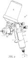
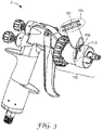
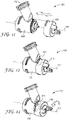
- the liquid spray gun 2 comprises a handle 4, a trigger 5, a connection for an external pressure source 6, a liquid spray gun body 3, a liquid needle adjustment control knob 9, a shaping air control knob 8, and a liquid spray gun nozzle assembly 100.
- the liquid spray gun nozzle assembly 100 comprises a spray gun connection portion 120 that is removable and attachable at a nozzle assembly connection portion 200 on the spray gun body 3.
- the liquid spray gun nozzle assembly 100 comprises one end of a liquid spray gun coating liquid connector 104 (located at a coating liquid inlet portion 102), through which a coating liquid is supplied to the liquid spray gun 2 from an external liquid source 6'.
- the liquid connector 104 comprises a quick-connect coupler 105.
- a quick-connect coupler is described, for example, in U.S. provisional patent application number 62/430,388 (3M Docket No. 77385US002), entitled “Paint Spray Gun Coating Liquid Connector,” filed December 6, 2016 .
- Other liquid connectors are possible.
- the liquid connector 104 may comprise connections, or features of connections, described in WO2017/123707 ; WO2017/123714 ; WO2017/123715 ; WO2017/123718 ; and/or in U.S. Pat. Pub. Nos.
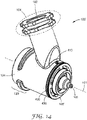
- the liquid connector 104 may comprise a gravity-fed spray gun paint reservoir connector, an example of which is shown in FIGS. 2-5 .
- a coating liquid flow path 110 through which the coating liquid flows from the liquid spray gun coating liquid connector 104 to a liquid nozzle 108 (see, e.g., FIG. 26 ).
- the coating liquid passes from the coating liquid inlet portion 102, along the coating liquid flow path 110, along a spray axis 101 parallel to a liquid needle 9', and ultimately is expelled from the liquid nozzle 108 upon depressing the trigger 5.
- the liquid needle 9' typically occludes the liquid nozzle 108.
- the liquid needle is sealed by one or more liquid needle sealing elements 111 towards the rearward end of the coating liquid flow path 110 (as seen, for example, in FIG.
- liquid needle 109 is not shown as the exemplary liquid spray gun nozzle assembly 100 is shown in a detached state.
- the trigger 5 When the trigger 5 is depressed, the liquid needle 9' is withdrawn from the liquid nozzle 108, thereby allowing the coating liquid to pass through.
- depressing the trigger activates the pressurized air supply to assist in (depending on the gun type) urging coating liquid through and/or from the liquid nozzle 108, atomizing the coating liquid, or shaping the coating liquid (e.g., via the air cap 115, described below).
- the travel of liquid needle 9' and the total air flow through the gun is adjusted via the liquid needle adjustment control 9.
- the relative volume of airflow among the air cap 115 (for shaping purposes) and a center air outlet 107 (for atomization purposes) is controlled via an air adjustment control 8.
- the forward end of the nozzle body 100' comprises a nozzle plate 108' which comprises the liquid nozzle 108 along with air guiding apparatus to guide shaping air and atomization air to the shaping air zone 442 and the center air zone 444 (described elsewhere) in the assembled air cap 115.
- the nozzle plate 108' is optionally provided as a separate part that is sealingly secured to the nozzle body 100' by means of an adhesive, welding, or the like. In other embodiments, the nozzle plate 108' is integral with the nozzle body 100'.
- the liquid spray nozzle assembly comprises an air cap 115 affixed to the spraying end thereof.
- the air cap 115 can direct pressurized air advantageously toward the stream of coating liquid, e.g., via one or more shaping air outlets 116 located in one or more air horns 117, as it is expelled from the liquid nozzle 108 to assist in atomization of the coating liquid and shaping of the coating liquid jet into the desired spray pattern for a given application.
- the center air outlet 107 directs air around the liquid outlet 108 to draw the coating liquid from the liquid nozzle 108 and (if desired) also impinges upon the coating liquid to atomize it, creating a fine mist of droplets.
- one or more auxiliary air outlets 118 may be provided in the air cap 115 to further assist in shaping the spray pattern. Portions of the air cap 115, the center air outlet 107, the liquid nozzle 108, the air horns 117, the auxiliary air outlets 118, and the shaping air outlets 116 may be configured as described in U.S. Pat. Pub. Nos.
- 2016/0052003 A1 Liquid Spray gun, spray gun platform, and spray head assembly
- 2013/0327850 A1 Nozzle tips and spray head assemblies for liquid spray guns
- 2014/0246519 A1 Spray head assembly with integrated air cap/nozzle for a liquid spray gun
- 2013/0092760 A1 Spray head assemblies for liquid spray guns
- 2015/0069142 A1 Spray gun barrel with inseparable nozzle
- 2016/0151797 A1 Air caps with face geometry inserts for liquid spray guns
- 2016/0175861 A1 Nozzle assemblies, systems and related methods”
- the coating liquid is contained entirely within the liquid spray gun nozzle assembly 100, thus generally avoiding the need to clean the liquid spray gun body 3 after use.
- the external liquid source 6' may be a container that is directly affixed to the liquid spray gun nozzle assembly 100 (see, e.g., FIG. 2 ), or may comprise a remote reservoir that is connected to the liquid spray gun nozzle assembly 100 by way of a hose.
- the external liquid source is remotely pressurized (via a pressurized canister, a remote pump, or the like) to force the coating liquid into the liquid spray gun nozzle assembly 100.
- the coating liquid may be forced or pulled into the liquid spray gun nozzle assembly 100 under the force of gravity (again, see FIG. 2 ), by way of a negative pressure induced by a venturi at the liquid nozzle 108, by a local pump, or through a combination of the above. Because the external liquid source can vary as described, it is shown in schematic form in FIGS. 1 and 3 .
- the nozzle assembly connection portion 200 facilitates the attachment of the paint spray gun nozzle assembly 100 to the paint spray gun body 3 by way of a locking ring 210 as described in U.S. provisional patent application number 62/430,383 (3M Docket No. 77384US002), entitled “Spray Gun and Nozzle Assembly Attachment,” filed December 6, 2016.
- the connection between the paint spray gun nozzle assembly 100 and the paint spray gun body 3 may be carried out by other means, such as, for example, a threaded collar, by one or more lever elements 130 as described, for example, in U.S. patent 8,590,809 B2 to Escoto, Jr. et al.
- the paint spray gun nozzle assembly 100 is integral with (or at least not readily removable from) the spray gun body.
- a liquid needle 9' is affixed to the liquid spray gun body 3, such that cleaning of the liquid spray gun body 3 is generally limited to wiping or otherwise clearing the tip of the liquid needle after detaching the liquid spray gun nozzle assembly 100.
- the liquid needle may be housed in the liquid spray gun nozzle assembly 100 such that it is removable from the liquid spray gun body 3 along with the liquid spray gun nozzle assembly 100.
- the liquid spray gun nozzle assembly 100 if disposable, may be discarded after use such that no further cleanup is required.
- the liquid spray gun nozzle assembly 100 if reusable, is the only portion of the liquid spray gun 2 left to clean. Both configurations can result in reduced cleanup time and materials, such as solvents, compared to what is typically required in a conventional spray gun.
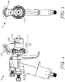
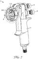
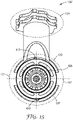
- the exemplary nozzle assembly connection portion 200 facilitates the attachment of the liquid spray gun nozzle assembly 100 to the liquid spray gun body 3 by way of a captured, rotatable locking ring 210, as seen in FIGS. 1-8 .
- FIG. 8 shows the nozzle assembly connection portion 200 as viewed along the spray axis 101.
- a corresponding view of the spray gun connection portion 120 of a liquid spray gun nozzle assembly 100 is shown in FIG. 24 .
- the spray gun nozzle assembly 100 may comprise an air cap 115.
- the air cap 115 may be retained to a nozzle body 100' of the spray gun nozzle assembly 100 by the air cap retention system 300.
- the air cap 115 may be rotatably retained thereon such that the air cap may be rotated to a first fan position and a second fan position, with each fan position allowing for a different spray pattern to be realized.
- the air cap 115 is both removably retained and rotatably retained on the nozzle body 100'.
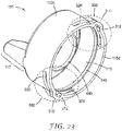
- the air cap 115 is shown apart from the nozzle body 100', exploded along the spray axis 101.
- the air cap comprises a forward end 115a, a retention end 115b, a sidewall 115c, and an endwall 115d located at the retention end.
- the spray axis 101 passes through the forward end 115a and the retention end 115b.
- forward refers to the end of the device or component of the device through which a coating liquid is sprayed (e.g., the end containing the liquid nozzle 108 when the air cap 115 is assembled to the nozzle body 100'), whereas “rearward” refers to the opposite direction along the spray axis 101.
- the air cap comprises one or more reception features 310
- the nozzle body comprises one or more corresponding nozzle body retainer features 410.
- the reception feature(s) 310 may be positioned proximate the retention end 115b of the air cap 115, which is the end that faces the nozzle body when the air cap 115 is installed.
- a reception feature 310 comprises a retainer window 312 through which a nozzle body retainer feature 410 may pass upon installation of the air cap 115 onto the nozzle body 100'.
- the air cap 115 is positioned as shown in FIG. 11 and is translated along the spray axis 101 and rotationally positioned so as to align the one or more reception features 310 with the corresponding nozzle body retainer features 410.
- the nozzle body retainer feature(s) pass through the retainer window(s) 312. Once thus positioned (see, e.g., FIG.
- the nozzle body retainer feature(s) have access to an air cap rotation guide 320 that permits the air cap 115 to rotate about the spray axis while being securely retained on the nozzle body 100' (see, e.g., FIG. 13 ).
- the air cap rotation guide 320 and the nozzle body retainer feature(s) 410 cooperate to prevent axial detachment of the air cap 115 from the nozzle body 100'.
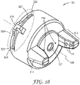
- the nozzle body retainer feature(s) 410 comprise protrusions from the outer wall 124 of the nozzle body 100' (see, e.g., FIGS. 14-17 ), while the retainer window(s) 312 and air cap rotation guide 320 comprise openings or recesses within the material of the air cap 115 (see, e.g., FIGS. 18-23 ).
- these features could be either swapped to the opposite part (e.g., a rotation guide may be instead or additionally placed on the nozzle body 100'), or be provided as a different combination of protrusions and recesses, so long as the functions and benefits described herein are realized.
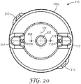
- the air cap rotation guide(s) 320 comprise first and second end stops 322, 324 to allow the user to position the air cap in preset rotational positions, as shown in FIG. 18 .
- a nozzle body retainer feature 410 will contact a first end stop 322 when the air horns 117 are positioned horizontally on either side of the liquid nozzle, such that a vertical spray pattern can be obtained.
- the air cap may be rotated 90 degrees in the clockwise direction until a nozzle body retainer feature 410 contacts a second end stop 324, such that the air horns 117 are positioned vertically above and below the liquid nozzle, so that a horizontal spray pattern can be obtained.
- the retainer window(s) 312 is located in an intermediate rotational position with respect to these preset positions.
- the retainer windows(s) 312 are located in a central rotational portion of the air cap rotation guide 320.
- the retainer window(s) 312 may be positioned along the air cap rotation guide 320 such that the air cap 115 may be installed and/or removed at a rotational position of 45 degrees.
- this angle need not be precisely 45 degrees, but may be chosen to be any angle that permits secure retention at desired preset rotational position(s) while allowing installation/removal at another position.
- the rotational position of the retainer window may be chosen in a range from 30 degrees to 60 degrees from either the first or second end stop.
- the position of the retainer window 312 may in some embodiments be chosen to correspond with the location of the first or second end stop (i.e., positioned at an angle of 0 degrees from an end stop).
- the air cap 115 may be removed for cleaning and/or replaced, if desired, by aligning the retainer window(s) 312 with the nozzle body retainer feature(s) 410 and pulling along the spray axis 101 to separate the air cap 115 from the nozzle body 100'. In this manner, the air cap 115 is rotated to a position where a rearward-oriented face 410' of the nozzle body retainer feature 410 will not bear against a retention wall 321, and can thus be detached axially along the spray axis 101.
- the user is provided with different air caps 115 for a given nozzle body 100' and may wish to swap them depending on the desired application.
- one air cap may comprise a different air horn geometry and/or different shaping air outlets, or may not contain any air horns at all (such as where no pattern shaping is needed).
- the present disclosure allows for such swapping without the need for loose auxiliary parts (e.g., the typically-provided threaded ring) that might otherwise be lost or damaged.
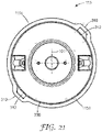
- the air cap 115 and/or the nozzle body 100' further or alternatively comprise one or more cooperating retention channels 420 and retention ribs 340.
- Such cooperating features may provide enhanced resistance against axial separation of the air cap 115 from the nozzle body 100'.
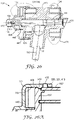
- An exemplary retention channel 420 may be seen in isolation in FIGS. 14 , 16, and 17 .
- An exemplary retention rib 340 may be seen in isolation in FIG. 23 .
- the features may be seen in cooperation in FIGS. 26 and 26A .
- a retention channel 420 may be positioned aft of an air cap sealing feature 430 (described below), defining the liquid nozzle 108 as the forward-facing end of the spray gun.
- a retention channel 420 may be positioned forward of an air cap sealing feature 430.
- the retention channel 420 need not comprise a two-sided channel as shown, but may comprise a one-sided step down in diameter into which a retention rib 340 may seat.
- cooperating retention channels 420 and retention ribs 340 may further provide tracking to assist with smooth, guided rotation of the air cap 115 with respect to the nozzle body 100'.
- a retention channel 420 may alternatively or additionally be provided on the air cap 115 and a cooperating retention rib 340 on the nozzle body 100'.
- a cooperating pair of a retention channel 420 and a retention rib 340 can act to provide a positive snap-fit of the air cap 115 onto the nozzle body 100'.
- Such snapping is realized by way of deformation and relaxation of the air cap 115 as it is pressed into place onto the nozzle body 100'.
- the retention rib 340 must deform outwardly to clear an outer wall of the nozzle body 100' (in this case the primary air cap sealing feature 430), and after so clearing will relax to become seated within the retention channel 420. If this relaxation is rapid, a snapping effect can be achieved.
- the snapping effect may be an effect that is felt by the user, but may also be audible if desired.
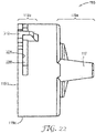
- the air cap 115 and/or the nozzle body 100' comprise a primary air cap sealing feature 430.
- the primary air cap sealing feature 430 comprises a ring-shaped member on the nozzle body 100'.
- the primary air cap sealing feature 430 presses against an air cap sealing surface 119 (which, as shown in the illustrated embodiments, comprises an inner wall of the air cap 115) with sufficient force and continuity to create a seal against compressed air, such seal being sufficient to essentially prevent compressed air from escaping the air cap around its rear perimeter under normal operating conditions.
- the primary air cap sealing feature 430 is comprised of the same material as the remainder of the nozzle body 100' (or another relatively non-resilient material), and provides a seal by virtue of simple cooperation with the air cap sealing surface 119.
- the air cap 115 may comprise a thin enough wall and/or a soft enough material as to slightly deform outwardly due to the force applied by the air cap sealing feature. In such cases, the fit between the air cap 115 and the nozzle body 100' may be described as an interference fit.
- a secondary air cap sealing feature 440 is further provided (see, e.g., FIGS. 26 and 26A ). While the primary air cap sealing feature provides a seal isolating the region inside the air cap from a surrounding atmosphere, the secondary air cap sealing feature provides a seal that is internal to the air cap and separates the internal region into more than one zone. In the embodiments shown, a shaping air zone 442 is isolated between the primary and secondary air cap sealing features, while a center air zone 444 is isolated within the secondary air cap sealing feature 440. As depicted, the secondary air cap sealing feature 440 comprises cooperating surfaces that create an interference fit to prevent air leakage, for example via material deformation as described in the preceding paragraph.
- sealing materials e.g., elastomers
- members e.g., o-rings, gaskets, etc.
- interaction between the primary air cap sealing feature 430 and the air cap sealing surface 119 further provides a degree of resistance against rotation of the air cap 115 relative to the nozzle body 100'.
- such resistance should be sufficient to prevent the air cap 115 from rotating on its own (e.g., in response to vibration, movement of the spray gun in use, or minor impacts), but permit the air cap 115 to be selectively rotationally positioned by hand about the spray axis 101 such that the desired spray pattern can be obtained by the user.
- the user may wish (even during spraying) to quickly rotate the air cap 115 to change the pattern from vertical to horizontal (or some angle therebetween) in order to facilitate holding the spray gun in differing orientations and/or spraying differently situated and/or shaped surfaces.
- the user may advantageously rapidly alter the orientation of the spray pattern without the need to first loosen any parts, without the use of tools, and without breaking or compromising the seal between the air cap 115 and the nozzle body 100' in the process.
- the one or more reception features 310 may further act as gripping features to facilitate the user's rotation of the air cap 115 to the desired rotational position, and also to assist with installation and/or removal of the air cap 115 from the nozzle body 100'.
- the air cap 115 may be provided as a disposable part, if desired, thereby minimizing replacement cost.
- the air cap 115 can be constructed of a resilient material (such as an injection molded polymer) not only to reduce cost but also to provide the necessary resilience needed to perform the sealing and rotational resistance functions as described herein (i.e., permitting the air cap sealing surface 119 to deform slightly to seal against the air cap sealing feature 430 and/or a retention rib 340 to seat into a cooperating retention channel 420.
Landscapes
- Nozzles (AREA)
Claims (10)
- Eine Sprühpistolenluftkappe (115), aufweisendein vorderes Ende (115a);ein Halteende (115b) gegenüber dem vorderen Ende;eine Sprühachse (101), die durch das Halteende und das vordere Ende hindurchgeht;eine Seitenwand (115c), die zwischen dem vorderen Ende und dem Halteende positioniert ist;wobei die Seitenwand ein erstes Luftkappenhaltesystem (300) aufweist, das aufweist:ein Aufnahmemerkmal (310), das ein Haltefenster (312) aufweist, das sich zum Halteende öffnet und sich zum vorderen Ende hin erstreckt; undeine Luftkappendrehführung (320), die das Haltefenster (312) schneidet und einem Bogen um die Sprühachse folgt, wobei die Luftkappendrehführung eine Haltewand (321) aufweist, die zum vorderen Ende zeigt,dadurch gekennzeichnet, dass sich das Haltefenster (312) durch die Seitenwand (115c) zum vorderen Ende (115a) hin erstreckt.
- Die Sprühpistolenluftkappe nach Anspruch 1, wobei sich die Luftkappendrehführung (320) durch die Seitenwand (115c) erstreckt.
- Die Sprühpistolenluftkappe nach einem der Ansprüche 1 bis 2, wobei die Luftkappendrehführung (320) einen ersten Endanschlag (322) aufweist, der an einem ersten Ende des Bogens positioniert ist.
- Die Sprühpistolenluftkappe nach Anspruch 3, wobei die Luftkappendrehführung (320) einen zweiten Endanschlag (324) aufweist, der an einem zweiten Ende des Bogens positioniert ist.
- Die Sprühpistolenluftkappe nach Anspruch 4, wobei das Haltefenster (312) an einer bogenförmigen Zwischenstelle zwischen dem ersten Endanschlag (322) und dem zweiten Endanschlag (324) positioniert ist.
- Eine Sprühpistolendüsenanordnung (100) aufweisend einen Düsenkörper (100') und eine Sprühpistolenluftkappe (115) nach einem der vorstehenden Ansprüche.
- Die Sprühpistolendüsenanordnung nach Anspruch 6, wobei der Düsenkörper (100') ein Düsenkörperhaltemerkmal (410) aufweist, das dazu ausgelegt ist, durch das Haltefenster (312) auf der Sprühpistolenluftkappe (115) hindurchzugehen.
- Die Sprühpistolendüsenanordnung nach Anspruch 7, wobei das Düsenkörperhaltemerkmal (410) dazu ausgelegt ist, durch die Luftkappendrehführung (320) hindurchzugehen.
- Die Sprühpistolendüsenanordnung nach einem der Ansprüche 6 bis 8, wobei der Düsenkörper (100') von einem Sprühpistolenkörper (3) trennbar ist.
- Ein Verfahren zum Montieren einer Luftkappe (115) an einem Düsenkörper (100'), aufweisendAusrichten eines Halteendes (115b) einer Sprühpistolenluftkappe (115) mit einem Düsenkörper (100') entlang einer Sprühachse (101), so dass ein Haltefenster (312) an der Sprühpistolenluftkappe mit einem Düsenkörperhaltemerkmal (410) drehausgerichtet ist;Verschieben der Sprühpistolenluftkappe (115) in Richtung des Düsenkörpers (100'), um zu bewirken, dass das Düsenkörperhaltemerkmal (410) in das Haltefenster (312) gelangt;Drehen der Sprühpistolenluftkappe (115) in einer ersten Richtung um die Sprühachse (101) in Bezug auf den Düsenkörper (100'), um zu bewirken, dass das Düsenkörperhaltemerkmal (410) entlang einer Luftkappendrehführung (320) fährt, bis das Düsenkörperhaltemerkmal einen ersten Endanschlag (322) berührt; undDrehen der Sprühpistolenluftkappe (115) in einer der ersten Richtung gegenüber liegenden zweiten Richtung um die Sprühachse (101) in Bezug auf den Düsenkörper (100'), um zu bewirken, dass das Düsenkörperhaltemerkmal (410) entlang der Luftkappendrehführung (320) fährt, bis das Düsenkörperhaltemerkmal (410) einen zweiten Endanschlag (324) berührt,wobei das Haltefenster (312) sich durch eine Seitenwand (115c) der Sprühpistolenluftkappe (115) in Richtung eines vorderen Endes (115a) der Sprühpistolenluftkappe (115) erstreckt und an einer bogenförmigen Zwischenstelle zwischen dem ersten Endanschlag (322) und dem zweiten Endanschlag (324) positioniert ist, wobei das Düsenkörperhaltemerkmal (410) quer durch das Haltefenster (312) hindurchgehen kann, wenn die Sprühpistolenluftkappe (115) zwischen dem ersten Endanschlag (322) und dem zweiten Endanschlag (324) gedreht wird.
Applications Claiming Priority (2)
| Application Number | Priority Date | Filing Date | Title |
|---|---|---|---|
| US201662430393P | 2016-12-06 | 2016-12-06 | |
| PCT/IB2017/057668 WO2018104871A1 (en) | 2016-12-06 | 2017-12-05 | Spray gun air cap with retention means |
Publications (2)
| Publication Number | Publication Date |
|---|---|
| EP3551338A1 EP3551338A1 (de) | 2019-10-16 |
| EP3551338B1 true EP3551338B1 (de) | 2022-11-09 |
Family
ID=61188848
Family Applications (1)
| Application Number | Title | Priority Date | Filing Date |
|---|---|---|---|
| EP17840492.7A Active EP3551338B1 (de) | 2016-12-06 | 2017-12-05 | Sprühpistolenluftkappe mit haltemitteln |
Country Status (8)
| Country | Link |
|---|---|
| US (1) | US20190337007A1 (de) |
| EP (1) | EP3551338B1 (de) |
| JP (1) | JP6983250B2 (de) |
| KR (1) | KR20190092420A (de) |
| CN (1) | CN110062662B (de) |
| AU (1) | AU2017372935B2 (de) |
| CA (1) | CA3046298A1 (de) |
| WO (1) | WO2018104871A1 (de) |
Families Citing this family (9)
| Publication number | Priority date | Publication date | Assignee | Title |
|---|---|---|---|---|
| EP3551341B1 (de) | 2016-12-06 | 2023-02-22 | 3M Innovative Properties Company | Sprühpistole und düsenanordnungsansatz |
| US11666934B2 (en) | 2016-12-12 | 2023-06-06 | 3M Innovative Properties Company | Spray gun and nozzle assembly attachment |
| EP3551340B1 (de) | 2016-12-12 | 2024-07-03 | 3M Innovative Properties Company | Sprühpistole und düsenanordnungsansatz |
| US11154884B2 (en) | 2016-12-12 | 2021-10-26 | 3M Innovative Properties Company | Spray gun and nozzle assembly attachment |
| WO2021191791A1 (en) | 2020-03-27 | 2021-09-30 | 3M Innovative Properties Company | Spray gun converter |
| US12208407B2 (en) | 2021-03-05 | 2025-01-28 | Graco Minnesota Inc. | Alignment tool for a spray gun air cap |
| CN113275145B (zh) * | 2021-07-23 | 2021-09-24 | 南通日旭重工科技有限公司 | 喷枪及具有其的油漆喷涂设备 |
| USD1055218S1 (en) | 2023-01-31 | 2024-12-24 | 3M Innovative Properties Company | Adhesive spray nozzle |
| CN221452972U (zh) * | 2023-12-08 | 2024-08-02 | 浙江普莱得电器股份有限公司 | 一种气动喷枪 |
Family Cites Families (31)
| Publication number | Priority date | Publication date | Assignee | Title |
|---|---|---|---|---|
| US4381081A (en) * | 1978-12-20 | 1983-04-26 | Nordson Corporation | Nozzle assembly for spray coating systems |
| AU4141889A (en) * | 1988-10-20 | 1990-04-26 | Nordson Corporation | Powder or solid particulate material spray gun |
| JP2562708Y2 (ja) * | 1992-12-28 | 1998-02-16 | 川崎重工業株式会社 | 転圧ローラ機械用散水ノズル保持具 |
| JP2575131Y2 (ja) * | 1993-01-07 | 1998-06-25 | 旭光学工業株式会社 | レンズのアクセサリ着脱機構 |
| US6820824B1 (en) | 1998-01-14 | 2004-11-23 | 3M Innovative Properties Company | Apparatus for spraying liquids, disposable containers and liners suitable for use therewith |
| US6536687B1 (en) | 1999-08-16 | 2003-03-25 | 3M Innovative Properties Company | Mixing cup adapting assembly |
| GB0224698D0 (en) | 2002-10-24 | 2002-12-04 | 3M Innovative Properties Co | Easy clean spray gun |
| US7484676B2 (en) | 2002-10-24 | 2009-02-03 | 3M Innovative Properties Company | Easy clean spray gun |
| NL1022624C2 (nl) * | 2002-11-20 | 2004-10-01 | Rudolphus Johannes Cornelissen | Verfspuitinrichting. |
| SE0301921L (sv) * | 2003-06-30 | 2005-01-25 | Baldwin Jimek Ab | Lufthuv |
| US6971590B2 (en) | 2003-12-30 | 2005-12-06 | 3M Innovative Properties Company | Liquid spray gun with manually rotatable frictionally retained air cap |
| JP2007279149A (ja) * | 2006-04-03 | 2007-10-25 | Nikon Corp | 光学装置及び光学システム |
| ATE422397T1 (de) * | 2006-07-22 | 2009-02-15 | Wagner Gmbh J | Spritzpistole |
| CN105107653B (zh) * | 2009-01-26 | 2018-01-09 | 3M创新有限公司 | 液体喷枪、喷枪平台和喷头组件 |
| DE102009053449A1 (de) * | 2009-08-05 | 2011-02-10 | J. Wagner Gmbh | Schlitzdüse |
| EP2468414B1 (de) * | 2010-12-23 | 2015-12-23 | P C Cox Limited | Druckluftbetätigte Spender |
| US9751100B2 (en) | 2011-02-09 | 2017-09-05 | 3M Innovative Properties Company | Nozzle tips and spray head assemblies for liquid spray guns |
| US8646812B2 (en) * | 2011-04-08 | 2014-02-11 | Apex Medical Corp. | Connector assembly |
| WO2013016474A1 (en) | 2011-07-28 | 2013-01-31 | 3M Innovative Properties Company | Spray head assembly with integrated air cap/nozzle for a liquid spray gun |
| RU2574755C2 (ru) | 2011-10-12 | 2016-02-10 | 3М Инновейтив Пропертиз Компани | Агрегаты головки распылителя для жидкостных пистолетов-распылителей |
| EP4000744A1 (de) | 2012-03-06 | 2022-05-25 | 3M Innovative Properties Co. | Spritzpistole mit internem boost-kanal |
| KR102111467B1 (ko) | 2012-03-23 | 2020-05-15 | 쓰리엠 이노베이티브 프로퍼티즈 컴파니 | 분리불가능 노즐을 갖는 스프레이 건 배럴 |
| EP3021982B1 (de) | 2013-07-15 | 2020-02-26 | 3M Innovative Properties Company | Luftkappen mit vorderen geometrieeinsätzen für flüssigkeitsspritzpistolen |
| DE102013013549A1 (de) * | 2013-08-13 | 2015-02-19 | Eisenmann Ag | Wechseleinrichtung für Beschichtungsmedien und Beschichtungssystem zum Beschichten von Gegenständen |
| CA2925892A1 (en) | 2013-10-11 | 2015-04-16 | 3M Innovative Properties Company | Nozzle assemblies, systems and related methods |
| MX2016016247A (es) | 2014-06-10 | 2017-03-31 | 3M Innovative Properties Co | Unidad de boquilla con deflectores externos. |
| WO2016033415A2 (en) | 2014-08-29 | 2016-03-03 | The Regents Of The University Of Michigan | Cleavable polymeric micelles |
| CA3011448A1 (en) | 2016-01-15 | 2017-07-20 | 3M Innovative Properties Company | Button-lock fluid connector for hand-held spray guns |
| CA3011425A1 (en) | 2016-01-15 | 2017-07-20 | 3M Innovative Properties Company | Modular spray gun lid assemblies and methods of design and use |
| PL3842154T3 (pl) | 2016-01-15 | 2025-06-09 | 3M Innovative Properties Company | Układ złącza do ręcznych pistoletów natryskowych |
| ES2866107T3 (es) | 2016-01-15 | 2021-10-19 | 3M Innovative Properties Co | Conector de fluidos de boca ancha para pistolas rociadoras portátiles |
-
2017
- 2017-12-05 CN CN201780075859.0A patent/CN110062662B/zh active Active
- 2017-12-05 EP EP17840492.7A patent/EP3551338B1/de active Active
- 2017-12-05 CA CA3046298A patent/CA3046298A1/en not_active Abandoned
- 2017-12-05 KR KR1020197016219A patent/KR20190092420A/ko not_active Withdrawn
- 2017-12-05 AU AU2017372935A patent/AU2017372935B2/en active Active
- 2017-12-05 WO PCT/IB2017/057668 patent/WO2018104871A1/en not_active Ceased
- 2017-12-05 US US16/466,716 patent/US20190337007A1/en not_active Abandoned
- 2017-12-05 JP JP2019549670A patent/JP6983250B2/ja active Active
Also Published As
| Publication number | Publication date |
|---|---|
| AU2017372935A1 (en) | 2019-06-20 |
| WO2018104871A1 (en) | 2018-06-14 |
| EP3551338A1 (de) | 2019-10-16 |
| CN110062662A (zh) | 2019-07-26 |
| US20190337007A1 (en) | 2019-11-07 |
| AU2017372935B2 (en) | 2020-04-16 |
| CN110062662B (zh) | 2021-07-27 |
| JP2019535518A (ja) | 2019-12-12 |
| CA3046298A1 (en) | 2018-06-14 |
| KR20190092420A (ko) | 2019-08-07 |
| JP6983250B2 (ja) | 2021-12-17 |
Similar Documents
| Publication | Publication Date | Title |
|---|---|---|
| EP3551338B1 (de) | Sprühpistolenluftkappe mit haltemitteln | |
| US12151258B2 (en) | Spray gun and nozzle assembly attachment | |
| EP3551340B1 (de) | Sprühpistole und düsenanordnungsansatz | |
| RU2376074C2 (ru) | Разбираемый вручную распылитель для жидкости | |
| RU2647738C2 (ru) | Форсунки в сборе, системы и соответствующие способы | |
| US11154884B2 (en) | Spray gun and nozzle assembly attachment | |
| WO2018104826A1 (en) | Paint spray gun coating liquid connector | |
| US20180141063A1 (en) | Cosmetic air brush | |
| US11666934B2 (en) | Spray gun and nozzle assembly attachment | |
| EP3508278A1 (de) | Kosmetischer luftpinsel |
Legal Events
| Date | Code | Title | Description |
|---|---|---|---|
| STAA | Information on the status of an ep patent application or granted ep patent |
Free format text: STATUS: UNKNOWN |
|
| STAA | Information on the status of an ep patent application or granted ep patent |
Free format text: STATUS: THE INTERNATIONAL PUBLICATION HAS BEEN MADE |
|
| PUAI | Public reference made under article 153(3) epc to a published international application that has entered the european phase |
Free format text: ORIGINAL CODE: 0009012 |
|
| STAA | Information on the status of an ep patent application or granted ep patent |
Free format text: STATUS: REQUEST FOR EXAMINATION WAS MADE |
|
| 17P | Request for examination filed |
Effective date: 20190611 |
|
| AK | Designated contracting states |
Kind code of ref document: A1 Designated state(s): AL AT BE BG CH CY CZ DE DK EE ES FI FR GB GR HR HU IE IS IT LI LT LU LV MC MK MT NL NO PL PT RO RS SE SI SK SM TR |
|
| AX | Request for extension of the european patent |
Extension state: BA ME |
|
| DAV | Request for validation of the european patent (deleted) | ||
| DAX | Request for extension of the european patent (deleted) | ||
| STAA | Information on the status of an ep patent application or granted ep patent |
Free format text: STATUS: EXAMINATION IS IN PROGRESS |
|
| 17Q | First examination report despatched |
Effective date: 20201119 |
|
| GRAP | Despatch of communication of intention to grant a patent |
Free format text: ORIGINAL CODE: EPIDOSNIGR1 |
|
| STAA | Information on the status of an ep patent application or granted ep patent |
Free format text: STATUS: GRANT OF PATENT IS INTENDED |
|
| INTG | Intention to grant announced |
Effective date: 20220603 |
|
| GRAS | Grant fee paid |
Free format text: ORIGINAL CODE: EPIDOSNIGR3 |
|
| GRAA | (expected) grant |
Free format text: ORIGINAL CODE: 0009210 |
|
| STAA | Information on the status of an ep patent application or granted ep patent |
Free format text: STATUS: THE PATENT HAS BEEN GRANTED |
|
| AK | Designated contracting states |
Kind code of ref document: B1 Designated state(s): AL AT BE BG CH CY CZ DE DK EE ES FI FR GB GR HR HU IE IS IT LI LT LU LV MC MK MT NL NO PL PT RO RS SE SI SK SM TR |
|
| REG | Reference to a national code |
Ref country code: GB Ref legal event code: FG4D |
|
| REG | Reference to a national code |
Ref country code: CH Ref legal event code: EP Ref country code: AT Ref legal event code: REF Ref document number: 1530011 Country of ref document: AT Kind code of ref document: T Effective date: 20221115 |
|
| REG | Reference to a national code |
Ref country code: DE Ref legal event code: R096 Ref document number: 602017063600 Country of ref document: DE |
|
| REG | Reference to a national code |
Ref country code: IE Ref legal event code: FG4D |
|
| REG | Reference to a national code |
Ref country code: LT Ref legal event code: MG9D |
|
| REG | Reference to a national code |
Ref country code: NL Ref legal event code: MP Effective date: 20221109 |
|
| REG | Reference to a national code |
Ref country code: AT Ref legal event code: MK05 Ref document number: 1530011 Country of ref document: AT Kind code of ref document: T Effective date: 20221109 |
|
| PG25 | Lapsed in a contracting state [announced via postgrant information from national office to epo] |
Ref country code: SE Free format text: LAPSE BECAUSE OF FAILURE TO SUBMIT A TRANSLATION OF THE DESCRIPTION OR TO PAY THE FEE WITHIN THE PRESCRIBED TIME-LIMIT Effective date: 20221109 Ref country code: PT Free format text: LAPSE BECAUSE OF FAILURE TO SUBMIT A TRANSLATION OF THE DESCRIPTION OR TO PAY THE FEE WITHIN THE PRESCRIBED TIME-LIMIT Effective date: 20230309 Ref country code: NO Free format text: LAPSE BECAUSE OF FAILURE TO SUBMIT A TRANSLATION OF THE DESCRIPTION OR TO PAY THE FEE WITHIN THE PRESCRIBED TIME-LIMIT Effective date: 20230209 Ref country code: LT Free format text: LAPSE BECAUSE OF FAILURE TO SUBMIT A TRANSLATION OF THE DESCRIPTION OR TO PAY THE FEE WITHIN THE PRESCRIBED TIME-LIMIT Effective date: 20221109 Ref country code: FI Free format text: LAPSE BECAUSE OF FAILURE TO SUBMIT A TRANSLATION OF THE DESCRIPTION OR TO PAY THE FEE WITHIN THE PRESCRIBED TIME-LIMIT Effective date: 20221109 Ref country code: ES Free format text: LAPSE BECAUSE OF FAILURE TO SUBMIT A TRANSLATION OF THE DESCRIPTION OR TO PAY THE FEE WITHIN THE PRESCRIBED TIME-LIMIT Effective date: 20221109 Ref country code: AT Free format text: LAPSE BECAUSE OF FAILURE TO SUBMIT A TRANSLATION OF THE DESCRIPTION OR TO PAY THE FEE WITHIN THE PRESCRIBED TIME-LIMIT Effective date: 20221109 |
|
| PG25 | Lapsed in a contracting state [announced via postgrant information from national office to epo] |
Ref country code: RS Free format text: LAPSE BECAUSE OF FAILURE TO SUBMIT A TRANSLATION OF THE DESCRIPTION OR TO PAY THE FEE WITHIN THE PRESCRIBED TIME-LIMIT Effective date: 20221109 Ref country code: PL Free format text: LAPSE BECAUSE OF FAILURE TO SUBMIT A TRANSLATION OF THE DESCRIPTION OR TO PAY THE FEE WITHIN THE PRESCRIBED TIME-LIMIT Effective date: 20221109 Ref country code: LV Free format text: LAPSE BECAUSE OF FAILURE TO SUBMIT A TRANSLATION OF THE DESCRIPTION OR TO PAY THE FEE WITHIN THE PRESCRIBED TIME-LIMIT Effective date: 20221109 Ref country code: IS Free format text: LAPSE BECAUSE OF FAILURE TO SUBMIT A TRANSLATION OF THE DESCRIPTION OR TO PAY THE FEE WITHIN THE PRESCRIBED TIME-LIMIT Effective date: 20230309 Ref country code: HR Free format text: LAPSE BECAUSE OF FAILURE TO SUBMIT A TRANSLATION OF THE DESCRIPTION OR TO PAY THE FEE WITHIN THE PRESCRIBED TIME-LIMIT Effective date: 20221109 Ref country code: GR Free format text: LAPSE BECAUSE OF FAILURE TO SUBMIT A TRANSLATION OF THE DESCRIPTION OR TO PAY THE FEE WITHIN THE PRESCRIBED TIME-LIMIT Effective date: 20230210 |
|
| PG25 | Lapsed in a contracting state [announced via postgrant information from national office to epo] |
Ref country code: NL Free format text: LAPSE BECAUSE OF FAILURE TO SUBMIT A TRANSLATION OF THE DESCRIPTION OR TO PAY THE FEE WITHIN THE PRESCRIBED TIME-LIMIT Effective date: 20221109 |
|
| P01 | Opt-out of the competence of the unified patent court (upc) registered |
Effective date: 20230530 |
|
| PG25 | Lapsed in a contracting state [announced via postgrant information from national office to epo] |
Ref country code: SM Free format text: LAPSE BECAUSE OF FAILURE TO SUBMIT A TRANSLATION OF THE DESCRIPTION OR TO PAY THE FEE WITHIN THE PRESCRIBED TIME-LIMIT Effective date: 20221109 Ref country code: RO Free format text: LAPSE BECAUSE OF FAILURE TO SUBMIT A TRANSLATION OF THE DESCRIPTION OR TO PAY THE FEE WITHIN THE PRESCRIBED TIME-LIMIT Effective date: 20221109 Ref country code: EE Free format text: LAPSE BECAUSE OF FAILURE TO SUBMIT A TRANSLATION OF THE DESCRIPTION OR TO PAY THE FEE WITHIN THE PRESCRIBED TIME-LIMIT Effective date: 20221109 Ref country code: DK Free format text: LAPSE BECAUSE OF FAILURE TO SUBMIT A TRANSLATION OF THE DESCRIPTION OR TO PAY THE FEE WITHIN THE PRESCRIBED TIME-LIMIT Effective date: 20221109 Ref country code: CZ Free format text: LAPSE BECAUSE OF FAILURE TO SUBMIT A TRANSLATION OF THE DESCRIPTION OR TO PAY THE FEE WITHIN THE PRESCRIBED TIME-LIMIT Effective date: 20221109 |
|
| REG | Reference to a national code |
Ref country code: CH Ref legal event code: PL |
|
| REG | Reference to a national code |
Ref country code: DE Ref legal event code: R097 Ref document number: 602017063600 Country of ref document: DE |
|
| REG | Reference to a national code |
Ref country code: BE Ref legal event code: MM Effective date: 20221231 |
|
| PG25 | Lapsed in a contracting state [announced via postgrant information from national office to epo] |
Ref country code: SK Free format text: LAPSE BECAUSE OF FAILURE TO SUBMIT A TRANSLATION OF THE DESCRIPTION OR TO PAY THE FEE WITHIN THE PRESCRIBED TIME-LIMIT Effective date: 20221109 Ref country code: LU Free format text: LAPSE BECAUSE OF NON-PAYMENT OF DUE FEES Effective date: 20221205 Ref country code: AL Free format text: LAPSE BECAUSE OF FAILURE TO SUBMIT A TRANSLATION OF THE DESCRIPTION OR TO PAY THE FEE WITHIN THE PRESCRIBED TIME-LIMIT Effective date: 20221109 |
|
| PLBE | No opposition filed within time limit |
Free format text: ORIGINAL CODE: 0009261 |
|
| STAA | Information on the status of an ep patent application or granted ep patent |
Free format text: STATUS: NO OPPOSITION FILED WITHIN TIME LIMIT |
|
| 26N | No opposition filed |
Effective date: 20230810 |
|
| GBPC | Gb: european patent ceased through non-payment of renewal fee |
Effective date: 20230209 |
|
| PG25 | Lapsed in a contracting state [announced via postgrant information from national office to epo] |
Ref country code: LI Free format text: LAPSE BECAUSE OF NON-PAYMENT OF DUE FEES Effective date: 20221231 Ref country code: IE Free format text: LAPSE BECAUSE OF NON-PAYMENT OF DUE FEES Effective date: 20221205 Ref country code: CH Free format text: LAPSE BECAUSE OF NON-PAYMENT OF DUE FEES Effective date: 20221231 |
|
| PG25 | Lapsed in a contracting state [announced via postgrant information from national office to epo] |
Ref country code: SI Free format text: LAPSE BECAUSE OF FAILURE TO SUBMIT A TRANSLATION OF THE DESCRIPTION OR TO PAY THE FEE WITHIN THE PRESCRIBED TIME-LIMIT Effective date: 20221109 Ref country code: BE Free format text: LAPSE BECAUSE OF NON-PAYMENT OF DUE FEES Effective date: 20221231 |
|
| PG25 | Lapsed in a contracting state [announced via postgrant information from national office to epo] |
Ref country code: GB Free format text: LAPSE BECAUSE OF NON-PAYMENT OF DUE FEES Effective date: 20230209 |
|
| PG25 | Lapsed in a contracting state [announced via postgrant information from national office to epo] |
Ref country code: GB Free format text: LAPSE BECAUSE OF NON-PAYMENT OF DUE FEES Effective date: 20230209 |
|
| PG25 | Lapsed in a contracting state [announced via postgrant information from national office to epo] |
Ref country code: HU Free format text: LAPSE BECAUSE OF FAILURE TO SUBMIT A TRANSLATION OF THE DESCRIPTION OR TO PAY THE FEE WITHIN THE PRESCRIBED TIME-LIMIT; INVALID AB INITIO Effective date: 20171205 |
|
| PG25 | Lapsed in a contracting state [announced via postgrant information from national office to epo] |
Ref country code: CY Free format text: LAPSE BECAUSE OF FAILURE TO SUBMIT A TRANSLATION OF THE DESCRIPTION OR TO PAY THE FEE WITHIN THE PRESCRIBED TIME-LIMIT Effective date: 20221109 |
|
| PG25 | Lapsed in a contracting state [announced via postgrant information from national office to epo] |
Ref country code: MK Free format text: LAPSE BECAUSE OF FAILURE TO SUBMIT A TRANSLATION OF THE DESCRIPTION OR TO PAY THE FEE WITHIN THE PRESCRIBED TIME-LIMIT Effective date: 20221109 Ref country code: IT Free format text: LAPSE BECAUSE OF FAILURE TO SUBMIT A TRANSLATION OF THE DESCRIPTION OR TO PAY THE FEE WITHIN THE PRESCRIBED TIME-LIMIT Effective date: 20221109 |
|
| PG25 | Lapsed in a contracting state [announced via postgrant information from national office to epo] |
Ref country code: MC Free format text: LAPSE BECAUSE OF FAILURE TO SUBMIT A TRANSLATION OF THE DESCRIPTION OR TO PAY THE FEE WITHIN THE PRESCRIBED TIME-LIMIT Effective date: 20221109 |
|
| PG25 | Lapsed in a contracting state [announced via postgrant information from national office to epo] |
Ref country code: TR Free format text: LAPSE BECAUSE OF FAILURE TO SUBMIT A TRANSLATION OF THE DESCRIPTION OR TO PAY THE FEE WITHIN THE PRESCRIBED TIME-LIMIT Effective date: 20221109 Ref country code: MC Free format text: LAPSE BECAUSE OF FAILURE TO SUBMIT A TRANSLATION OF THE DESCRIPTION OR TO PAY THE FEE WITHIN THE PRESCRIBED TIME-LIMIT Effective date: 20221109 |
|
| PG25 | Lapsed in a contracting state [announced via postgrant information from national office to epo] |
Ref country code: BG Free format text: LAPSE BECAUSE OF FAILURE TO SUBMIT A TRANSLATION OF THE DESCRIPTION OR TO PAY THE FEE WITHIN THE PRESCRIBED TIME-LIMIT Effective date: 20221109 |
|
| PG25 | Lapsed in a contracting state [announced via postgrant information from national office to epo] |
Ref country code: MT Free format text: LAPSE BECAUSE OF FAILURE TO SUBMIT A TRANSLATION OF THE DESCRIPTION OR TO PAY THE FEE WITHIN THE PRESCRIBED TIME-LIMIT Effective date: 20221109 |
|
| PGFP | Annual fee paid to national office [announced via postgrant information from national office to epo] |
Ref country code: DE Payment date: 20251126 Year of fee payment: 9 |
|
| PGFP | Annual fee paid to national office [announced via postgrant information from national office to epo] |
Ref country code: FR Payment date: 20251120 Year of fee payment: 9 |