EP3551340B1 - Sprühpistole und düsenanordnungsansatz - Google Patents
Sprühpistole und düsenanordnungsansatz Download PDFInfo
- Publication number
- EP3551340B1 EP3551340B1 EP17818296.0A EP17818296A EP3551340B1 EP 3551340 B1 EP3551340 B1 EP 3551340B1 EP 17818296 A EP17818296 A EP 17818296A EP 3551340 B1 EP3551340 B1 EP 3551340B1
- Authority
- EP
- European Patent Office
- Prior art keywords
- spray gun
- liquid
- nozzle assembly
- liquid spray
- assembly
- Prior art date
- Legal status (The legal status is an assumption and is not a legal conclusion. Google has not performed a legal analysis and makes no representation as to the accuracy of the status listed.)
- Active
Links
Images


Classifications
-
- B—PERFORMING OPERATIONS; TRANSPORTING
- B05—SPRAYING OR ATOMISING IN GENERAL; APPLYING FLUENT MATERIALS TO SURFACES, IN GENERAL
- B05B—SPRAYING APPARATUS; ATOMISING APPARATUS; NOZZLES
- B05B7/00—Spraying apparatus for discharge of liquids or other fluent materials from two or more sources, e.g. of liquid and air, of powder and gas
- B05B7/24—Spraying apparatus for discharge of liquids or other fluent materials from two or more sources, e.g. of liquid and air, of powder and gas with means, e.g. a container, for supplying liquid or other fluent material to a discharge device
- B05B7/2402—Apparatus to be carried on or by a person, e.g. by hand; Apparatus comprising containers fixed to the discharge device
- B05B7/2405—Apparatus to be carried on or by a person, e.g. by hand; Apparatus comprising containers fixed to the discharge device using an atomising fluid as carrying fluid for feeding, e.g. by suction or pressure, a carried liquid from the container to the nozzle
- B05B7/2408—Apparatus to be carried on or by a person, e.g. by hand; Apparatus comprising containers fixed to the discharge device using an atomising fluid as carrying fluid for feeding, e.g. by suction or pressure, a carried liquid from the container to the nozzle characterised by the container or its attachment means to the spray apparatus
-
- B—PERFORMING OPERATIONS; TRANSPORTING
- B05—SPRAYING OR ATOMISING IN GENERAL; APPLYING FLUENT MATERIALS TO SURFACES, IN GENERAL
- B05B—SPRAYING APPARATUS; ATOMISING APPARATUS; NOZZLES
- B05B15/00—Details of spraying plant or spraying apparatus not otherwise provided for; Accessories
- B05B15/60—Arrangements for mounting, supporting or holding spraying apparatus
- B05B15/65—Mounting arrangements for fluid connection of the spraying apparatus or its outlets to flow conduits
- B05B15/652—Mounting arrangements for fluid connection of the spraying apparatus or its outlets to flow conduits whereby the jet can be oriented
- B05B15/654—Mounting arrangements for fluid connection of the spraying apparatus or its outlets to flow conduits whereby the jet can be oriented using universal joints
-
- B—PERFORMING OPERATIONS; TRANSPORTING
- B05—SPRAYING OR ATOMISING IN GENERAL; APPLYING FLUENT MATERIALS TO SURFACES, IN GENERAL
- B05B—SPRAYING APPARATUS; ATOMISING APPARATUS; NOZZLES
- B05B7/00—Spraying apparatus for discharge of liquids or other fluent materials from two or more sources, e.g. of liquid and air, of powder and gas
- B05B7/02—Spray pistols; Apparatus for discharge
- B05B7/025—Nozzles having elongated outlets, e.g. slots, for the material to be sprayed
-
- B—PERFORMING OPERATIONS; TRANSPORTING
- B05—SPRAYING OR ATOMISING IN GENERAL; APPLYING FLUENT MATERIALS TO SURFACES, IN GENERAL
- B05B—SPRAYING APPARATUS; ATOMISING APPARATUS; NOZZLES
- B05B7/00—Spraying apparatus for discharge of liquids or other fluent materials from two or more sources, e.g. of liquid and air, of powder and gas
- B05B7/24—Spraying apparatus for discharge of liquids or other fluent materials from two or more sources, e.g. of liquid and air, of powder and gas with means, e.g. a container, for supplying liquid or other fluent material to a discharge device
- B05B7/2402—Apparatus to be carried on or by a person, e.g. by hand; Apparatus comprising containers fixed to the discharge device
- B05B7/2467—Apparatus to be carried on or by a person, e.g. by hand; Apparatus comprising containers fixed to the discharge device a liquid being fed by a pressure generated in the container, which is not produced by a carrying fluid
-
- B—PERFORMING OPERATIONS; TRANSPORTING
- B05—SPRAYING OR ATOMISING IN GENERAL; APPLYING FLUENT MATERIALS TO SURFACES, IN GENERAL
- B05B—SPRAYING APPARATUS; ATOMISING APPARATUS; NOZZLES
- B05B7/00—Spraying apparatus for discharge of liquids or other fluent materials from two or more sources, e.g. of liquid and air, of powder and gas
- B05B7/24—Spraying apparatus for discharge of liquids or other fluent materials from two or more sources, e.g. of liquid and air, of powder and gas with means, e.g. a container, for supplying liquid or other fluent material to a discharge device
- B05B7/2402—Apparatus to be carried on or by a person, e.g. by hand; Apparatus comprising containers fixed to the discharge device
- B05B7/2478—Gun with a container which, in normal use, is located above the gun
-
- B—PERFORMING OPERATIONS; TRANSPORTING
- B05—SPRAYING OR ATOMISING IN GENERAL; APPLYING FLUENT MATERIALS TO SURFACES, IN GENERAL
- B05B—SPRAYING APPARATUS; ATOMISING APPARATUS; NOZZLES
- B05B7/00—Spraying apparatus for discharge of liquids or other fluent materials from two or more sources, e.g. of liquid and air, of powder and gas
- B05B7/02—Spray pistols; Apparatus for discharge
- B05B7/08—Spray pistols; Apparatus for discharge with separate outlet orifices, e.g. to form parallel jets, i.e. the axis of the jets being parallel, to form intersecting jets, i.e. the axis of the jets converging but not necessarily intersecting at a point
- B05B7/0807—Spray pistols; Apparatus for discharge with separate outlet orifices, e.g. to form parallel jets, i.e. the axis of the jets being parallel, to form intersecting jets, i.e. the axis of the jets converging but not necessarily intersecting at a point to form intersecting jets
- B05B7/0815—Spray pistols; Apparatus for discharge with separate outlet orifices, e.g. to form parallel jets, i.e. the axis of the jets being parallel, to form intersecting jets, i.e. the axis of the jets converging but not necessarily intersecting at a point to form intersecting jets with at least one gas jet intersecting a jet constituted by a liquid or a mixture containing a liquid for controlling the shape of the latter
Definitions
- the liquid connector 104 may comprise a gravity-fed spray gun paint reservoir connector, an example of which is shown in FIG. 2 of 62/430,383 .
- the liquid connector 104 comprises a quick-connect coupler 105 that comprises a second connector portion 800 on the spray gun liquid nozzle assembly 100 and a first connector portion 900 on a lid body (not shown) that facilitates connection to an external liquid source 6' (as shown in 62/430,383 ).
- liquid connector 104 is as described in U.S. patent application publication US 2017/0203887 .
- a liquid spray gun nozzle assembly 100 as shown and described herein is depicted in FIGS. 24A and 24B of US 2017/0203887 (there labeled as spray gun nozzle unit 570) and its connector format 76' is described in full detail therein.
- a second connector portion 800 comprises a second connector format 876 corresponding to the second connector format 76' described in US 2017/0203887 .
- the liquid connector 104 (with second connector format 876) is brought into position against a first connector format 74 of a lid body 70 and rotated into a locking configuration therewith (as shown and described in US 2017/0203887 ). Although such features and their corresponding function(s) are described in US 2017/0203887 .
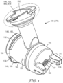
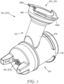
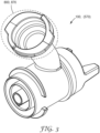
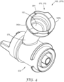
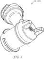
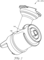
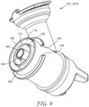
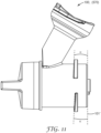
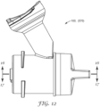
- FIGS. 1-17 and 19 an embodiment of a spray gun nozzle unit 570 (or 100) in accordance with principles of the present disclosure is shown in FIGS. 1-17 and 19 (or in FIGS. 24A and 24B of US 2017/0203887 ), and can be provided as part of a spray gun.
- the nozzle unit 570 (or 100) includes an inlet port 572 and a spray nozzle assembly 574 (referenced generally).
- the inlet port 572 includes an inlet tube 576 and the second connection format 76' (referenced generally).
- the inlet tube 576 is fluidly connected to an outlet 578 of the spray nozzle assembly 574.
- the second connection format 76' can have the constructions as described in US 2017/0203887 , including the base 360', the first lock structure 362a, the second lock structure 362b, and the tracking face 364.
- the second connection format 76' as provided with the nozzle unit 570 is thus configured for direct connection to a reservoir 52 as described in US 2017/0203887 .
- the spray gun inlet port 572 can be considered to be a component or part of the spray gun reservoir system of US 2017/0203887 .
- the connector formats can be swapped so that the geometry described for the liquid spray nozzle assembly 100 (570) is on a lid body 70, and vice versa.
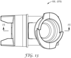
- a coating liquid flow path 110 through which the coating liquid flows from the liquid spray gun coating liquid connector 104 to a liquid nozzle 108 (see, e.g., FIG. 15 ).
- the coating liquid passes from the coating liquid inlet portion 102, along the coating liquid flow path 110, along a spray axis 101 parallel to a liquid needle 9', and ultimately is expelled from the liquid nozzle 108 upon depressing the trigger 5.
- the liquid needle 9' typically occludes the liquid nozzle 108.
- the liquid needle is sealed by one or more liquid needle sealing elements 111 towards the rearward end of the coating liquid flow path 110 (as seen, for example, in FIGS.
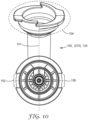
- one or more auxiliary air outlets 118 may be provided in the air cap 115 to further assist in shaping the spray pattern.
- the air cap 115, the center air outlet 107, the liquid nozzle 108, the air horns 117, the auxiliary air outlets 118, and the shaping air outlets 116 may be configured as described in U.S. patent application number 62/430,393 (3M Docket No. 79035US002), entitled “Spray Gun Air Cap Retention Means," and/or in U.S. Pat. Pub. Nos.
- the external liquid source 6' may be a container that is directly affixed to the liquid spray gun nozzle assembly 100, or may comprise a remote reservoir that is connected to the liquid spray gun nozzle assembly 100 by way of a hose.
- the external liquid source is remotely pressurized (via a pressurized canister, a remote pump, or the like) to force the coating liquid into the liquid spray gun nozzle assembly 100.
- the coating liquid may be forced or pulled into the liquid spray gun nozzle assembly 100 under the force of gravity, by way of a negative pressure induced by a venturi at the liquid nozzle 108, by a local pump, or through a combination of the above. Because the external liquid source can vary as described, it is shown in schematic form in FIGS. 1 and 3 of 62/430,383.
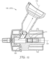
- the sealing function is provided by deformation of one or more of the components themselves.
- the relative geometry and materials of the liquid spray gun nozzle assembly 100 and the nozzle assembly connection portion 200 are chosen to interact to create a seal without the provision of separate components or special gasketing materials.
- the first and second sealing member 168 and 172 are provided as tapering rims that terminate in a pointed profile. These pointed profiles interact with the corresponding first and second sealing seats 268 and 272 such that either (depending on the relative hardness of the materials chosen) (i) the pointed profiles are slightly "crumpled” to form a seal; or (ii) the pointed profiles slightly bite or dig into the sealing seat(s).
Landscapes
- Nozzles (AREA)
Claims (14)
- Eine Flüssigkeitsspritzpistolendüsenanordnung (100) für eine schwerkraftgespeiste Flüssigkeitsspritzpistole (2), aufweisendeinen Beschichtungsflüssigkeitseinlassabschnitt (102), aufweisend einen Flüssigkeitsverbinder (104) für eine Verbindung mit einer externen Flüssigkeitsquelle (6');einen Beschichtungsflüssigkeitsauslassabschnitt, aufweisend eine Flüssigkeitsdüse (108) zum Spritzen einer Beschichtungsflüssigkeit, die in die Düsenanordnung (100) zugeführt wird durch den Beschichtungsflüssigkeitseinlassabschnitt (102), wobei die Flüssigkeitsdüse (108) entlang einer Spritzachse (101) eingerichtet ist;einen Beschichtungsflüssigkeitsströmungsweg (110), der den Beschichtungsflüssigkeitseinlassabschnitt (102) mit der Flüssigkeitsdüse (108) fluidisch verbindet;einen Spritzpistolenverbindungsabschnitt (120) gegenüberliegend dem Beschichtungsflüssigkeitsauslassabschnitt, der angepasst ist, um die Flüssigkeitsspritzpistolendüsenanordnung (100) mit einem kompatiblen Flüssigkeitsspritzpistolenkörper (3) zu verbinden, der Spritzpistolenverbindungsabschnitt (120) aufweisend eine Düsenanordnungsdichtungsoberfläche, die angepasst ist, um die Flüssigkeitsspritzpistolendüsenanordnung (100) mit dem kompatiblen Flüssigkeitsspritzpistolenkörper (3) abzudichten, die Düsenanordnungsdichtungsoberfläche aufweisend ein erstes und ein zweites Dichtungselement (168, 172), die jeweils zirkulär und konzentrisch zueinander sind, wobei das erste und das zweite Dichtungselement (168, 172) um eine Spritzachse (101) herum konzentrisch sind, unddadurch gekennzeichnet, dass bei der Verbindung der Flüssigkeitsspritzpistolendüsenanordnung (100) mit dem kompatiblen Flüssigkeitsspritzpistolenkörper (3) eine Formluftzone (176) in der Gestalt eines geschlossenen Rings konzentrisch zu dem ersten und dem zweiten Dichtungselement (168, 172) und zwischen diesen isoliert ist.
- Die Flüssigkeitsspritzpistolendüsenanordnung (100) nach Anspruch 1, wobei bei der Verbindung mit dem kompatiblen Flüssigkeitsspritzpistolenkörper (3) eine zentrale Luftzone (180) innerhalb des zweiten Dichtungselements (172) isoliert ist.
- Die Flüssigkeitsspritzpistolendüsenanordnung (100) nach einem der Ansprüche 1 bis 2, wobei die Düsenanordnungsdichtungsoberfläche ein drittes Dichtungselement (184) aufweist, das zirkulär und konzentrisch zu dem ersten und dem zweiten Dichtungselement (168, 172) ist.
- Die Flüssigkeitsspritzpistolendüsenanordnung (100) nach Anspruch 3, wobei bei der Verbindung mit dem kompatiblen Flüssigkeitsspritzpistolenkörper (3) eine zentrale Luftzone (180) zwischen dem zweiten und dem dritten Dichtungselement (172, 184) isoliert ist.
- Die Flüssigkeitsspritzpistolendüsenanordnung (100) nach einem der Ansprüche 3 oder 4, wobei bei der Verbindung mit dem kompatiblen Flüssigkeitsspritzpistolenkörper (3) eine Flüssigkeitsnadel (9') innerhalb des dritten Dichtungselements (184) isoliert ist.
- Die Flüssigkeitsspritzpistolendüsenanordnung (100) nach einem der Ansprüche 1 bis 5, wobei der Flüssigkeitsverbinder (104) einen zweiten Verbinderabschnitt (800) aufweist, aufweisend ein zweites Verbinderformat (876), aufweisend eine Nachlauffläche (364) und eine Verriegelungsstruktur (362a, 362b).
- Die Flüssigkeitsspritzpistolendüsenanordnung (100) nach Anspruch 6, ferner aufweisend einen Deckelkörper (70), der für die Verbindung mit dem Flüssigkeitsverbinder (104) konfiguriert ist, der Deckelkörper aufweisend einen ersten Verbinderabschnitt (900), aufweisend ein erstes Verbinderformat (74), das konfiguriert ist, um sich mit dem zweiten Verbinderformat (876) an dem Flüssigkeitsverbinder (104) für eine Anordnung auf dem Flüssigkeitsverbinder (104) zu verbinden.
- Die Flüssigkeitsspritzpistolendüsenanordnung (100) nach Anspruch 7, wobei das erste Verbinderformat eine Führungsoberfläche und eine Retentionsstruktur aufweist, wobei die Verriegelungsstruktur (362a, 362b) konfiguriert ist, um mit der Retentionsstruktur selektiv eine Schnittstelle zu bilden, und die Nachlauffläche (364) konfiguriert ist, um mit der Führungsoberfläche eine Schnittstelle zu bilden.
- Eine Flüssigkeitsspritzpistolenanordnung, aufweisendeinen Flüssigkeitsspritzpistolenkörper (3); undeine Flüssigkeitsspritzpistolendüsenanordnung (100) nach einem der Ansprüche 1 bis 8.
- Die Flüssigkeitsspritzpistolenanordnung nach Anspruch 9, wobei der Flüssigkeitsspritzpistolenkörper (3) einen aufgenommenen drehbaren Verriegelungsring (210) für die Verbindung der Flüssigkeitsspritzpistolendüsenanordnung (100) aufweist.
- Die Flüssigkeitsspritzpistolenanordnung nach Anspruch 10, wobei der aufgenommene drehbare Verriegelungsring (210) eine erste und eine zweite Nockennasen (230) aufweist, die angepasst sind, um mit der ersten und der zweiten Nockenoberflächen (148) an der Flüssigkeitsspritzpistolendüsenanordnung (100) zusammenzuwirken.
- Die Flüssigkeitsspritzpistolenanordnung nach Anspruch 11, wobei der aufgenommene drehbare Verriegelungsring (210) um die Spritzachse (101) herum zu einer Anordnungsposition (214) und einer verriegelten Position (218) drehbar ist, wobeidie erste und die zweite Nockennase (230) in der Anordnungsposition (214) mit dem ersten beziehungsweise dem zweiten Zugangsfenster (152, 156) ausgerichtet sind, um eine Installation oder Entfernung der Flüssigkeitsspritzpistolendüsenanordnung (100) zu ermöglichen; unddie erste und die zweite Nockennase (230) in der verriegelten Position (218) an der ersten beziehungsweise der zweiten Nockenoberfläche (148) anliegen, um die Flüssigkeitsspritzpistolenanordnung (100) gegen den Flüssigkeitsspritzpistolenkörper (3) zu verriegeln.
- Ein Verfahren zum Verwenden einer Flüssigkeitsspritzpistolenanordnung nach einem der Ansprüche 9 bis 12, aufweisend ein Installieren der Flüssigkeitsspritzpistolendüsenanordnung (100) auf dem Flüssigkeitsspritzpistolenkörper (3).
- Das Verfahren nach Anspruch 13, aufweisend ein Entfernen der Flüssigkeitsspritzdüsenanordnung (100) von dem Flüssigkeitsspritzpistolenkörper (3).
Applications Claiming Priority (2)
| Application Number | Priority Date | Filing Date | Title |
|---|---|---|---|
| US201662433045P | 2016-12-12 | 2016-12-12 | |
| PCT/IB2017/057754 WO2018109624A1 (en) | 2016-12-12 | 2017-12-08 | Spray gun and nozzle assembly attachment |
Publications (2)
| Publication Number | Publication Date |
|---|---|
| EP3551340A1 EP3551340A1 (de) | 2019-10-16 |
| EP3551340B1 true EP3551340B1 (de) | 2024-07-03 |
Family
ID=60782291
Family Applications (1)
| Application Number | Title | Priority Date | Filing Date |
|---|---|---|---|
| EP17818296.0A Active EP3551340B1 (de) | 2016-12-12 | 2017-12-08 | Sprühpistole und düsenanordnungsansatz |
Country Status (5)
| Country | Link |
|---|---|
| US (1) | US11154894B2 (de) |
| EP (1) | EP3551340B1 (de) |
| CN (1) | CN110114148A (de) |
| CA (1) | CA3046732A1 (de) |
| WO (1) | WO2018109624A1 (de) |
Families Citing this family (7)
| Publication number | Priority date | Publication date | Assignee | Title |
|---|---|---|---|---|
| EP3551341B1 (de) * | 2016-12-06 | 2023-02-22 | 3M Innovative Properties Company | Sprühpistole und düsenanordnungsansatz |
| US11666934B2 (en) * | 2016-12-12 | 2023-06-06 | 3M Innovative Properties Company | Spray gun and nozzle assembly attachment |
| US11154884B2 (en) | 2016-12-12 | 2021-10-26 | 3M Innovative Properties Company | Spray gun and nozzle assembly attachment |
| WO2021191791A1 (en) | 2020-03-27 | 2021-09-30 | 3M Innovative Properties Company | Spray gun converter |
| JP2024519528A (ja) * | 2021-05-14 | 2024-05-15 | マーティン ルーダ 1.ユージー(ハフトゥングスベシュレンクト) | 塗料導入デバイス、スプレーガン、及びアセンブリ |
| EP4539998A1 (de) | 2022-06-14 | 2025-04-23 | 3M Innovative Properties Company | Nahtversiegelungsadapter für spritzpistole |
| USD1055218S1 (en) | 2023-01-31 | 2024-12-24 | 3M Innovative Properties Company | Adhesive spray nozzle |
Family Cites Families (35)
| Publication number | Priority date | Publication date | Assignee | Title |
|---|---|---|---|---|
| US5836517A (en) | 1995-01-03 | 1998-11-17 | Ransburg Corporation | Spray gun with fluid valve |
| DE19612524A1 (de) * | 1996-03-29 | 1997-10-02 | Metanoia Ag | Spritzpistole |
| US6820824B1 (en) | 1998-01-14 | 2004-11-23 | 3M Innovative Properties Company | Apparatus for spraying liquids, disposable containers and liners suitable for use therewith |
| US6536687B1 (en) | 1999-08-16 | 2003-03-25 | 3M Innovative Properties Company | Mixing cup adapting assembly |
| DE10135104C1 (de) | 2001-07-19 | 2002-09-12 | Sata Farbspritztechnik | Farbspritzpistole |
| US6854667B2 (en) | 2001-09-06 | 2005-02-15 | Graco Minnesota Inc. | Spray gun having indexing air cap with quick release retaining ring |
| GB0224698D0 (en) | 2002-10-24 | 2002-12-04 | 3M Innovative Properties Co | Easy clean spray gun |
| US7484676B2 (en) | 2002-10-24 | 2009-02-03 | 3M Innovative Properties Company | Easy clean spray gun |
| US7032839B2 (en) | 2003-12-30 | 2006-04-25 | 3M Innovative Properties Company | Liquid spray gun with manually separable portions |
| US20050242207A1 (en) | 2004-05-03 | 2005-11-03 | Ramon Tejeda | Spray gun coupled with a quick connect ring nut and a spring-loaded air diverter and a method for assembling the same |
| CN105107653B (zh) | 2009-01-26 | 2018-01-09 | 3M创新有限公司 | 液体喷枪、喷枪平台和喷头组件 |
| US9192950B2 (en) * | 2009-11-20 | 2015-11-24 | Wagner Spray Tech Corporation | Sprayer for a fluid delivery system |
| US9751100B2 (en) | 2011-02-09 | 2017-09-05 | 3M Innovative Properties Company | Nozzle tips and spray head assemblies for liquid spray guns |
| US20130020414A1 (en) | 2011-07-20 | 2013-01-24 | Sunless, Inc. | Spray gun nozzle tip with integrated seal and auto aligining fluid path |
| WO2013016474A1 (en) | 2011-07-28 | 2013-01-31 | 3M Innovative Properties Company | Spray head assembly with integrated air cap/nozzle for a liquid spray gun |
| RU2574755C2 (ru) | 2011-10-12 | 2016-02-10 | 3М Инновейтив Пропертиз Компани | Агрегаты головки распылителя для жидкостных пистолетов-распылителей |
| EP4000744A1 (de) | 2012-03-06 | 2022-05-25 | 3M Innovative Properties Co. | Spritzpistole mit internem boost-kanal |
| KR102111467B1 (ko) | 2012-03-23 | 2020-05-15 | 쓰리엠 이노베이티브 프로퍼티즈 컴파니 | 분리불가능 노즐을 갖는 스프레이 건 배럴 |
| EP3021982B1 (de) | 2013-07-15 | 2020-02-26 | 3M Innovative Properties Company | Luftkappen mit vorderen geometrieeinsätzen für flüssigkeitsspritzpistolen |
| CA2925892A1 (en) | 2013-10-11 | 2015-04-16 | 3M Innovative Properties Company | Nozzle assemblies, systems and related methods |
| MX2016016247A (es) | 2014-06-10 | 2017-03-31 | 3M Innovative Properties Co | Unidad de boquilla con deflectores externos. |
| CN204134775U (zh) * | 2014-07-31 | 2015-02-04 | 萨塔有限两合公司 | 喷枪 |
| WO2016033415A2 (en) | 2014-08-29 | 2016-03-03 | The Regents Of The University Of Michigan | Cleavable polymeric micelles |
| DE202014105806U1 (de) * | 2014-12-02 | 2015-02-25 | G-Mate Ag | Farbsprüheinheit zur reversiblen Anordnung an einer Spritzpistole |
| EP4364855A3 (de) * | 2015-03-04 | 2024-07-17 | Martin Ruda 1. UG (haftungsbeschränkt). | Spritzpistole, flüssigkeitseinrichtung und set mit einer flüssigkeitsleiteinrichtung |
| DE102015009109A1 (de) | 2015-07-19 | 2017-01-19 | Rainer Hirl | Musikinstrumentenanordnung |
| ES2866107T3 (es) | 2016-01-15 | 2021-10-19 | 3M Innovative Properties Co | Conector de fluidos de boca ancha para pistolas rociadoras portátiles |
| CA3011448A1 (en) | 2016-01-15 | 2017-07-20 | 3M Innovative Properties Company | Button-lock fluid connector for hand-held spray guns |
| US10689165B2 (en) | 2016-01-15 | 2020-06-23 | 3M Innovative Properties Company | Reservoir systems for hand-held spray guns and methods of use |
| PL3842154T3 (pl) | 2016-01-15 | 2025-06-09 | 3M Innovative Properties Company | Układ złącza do ręcznych pistoletów natryskowych |
| CA3011425A1 (en) | 2016-01-15 | 2017-07-20 | 3M Innovative Properties Company | Modular spray gun lid assemblies and methods of design and use |
| CN110062662B (zh) | 2016-12-06 | 2021-07-27 | 3M创新有限公司 | 具有保持装置的喷枪气嘴 |
| WO2018104826A1 (en) | 2016-12-06 | 2018-06-14 | 3M Innovative Properties Company | Paint spray gun coating liquid connector |
| EP3551341B1 (de) | 2016-12-06 | 2023-02-22 | 3M Innovative Properties Company | Sprühpistole und düsenanordnungsansatz |
| US11154884B2 (en) | 2016-12-12 | 2021-10-26 | 3M Innovative Properties Company | Spray gun and nozzle assembly attachment |
-
2017
- 2017-12-08 EP EP17818296.0A patent/EP3551340B1/de active Active
- 2017-12-08 WO PCT/IB2017/057754 patent/WO2018109624A1/en not_active Ceased
- 2017-12-08 US US16/468,555 patent/US11154894B2/en active Active
- 2017-12-08 CA CA3046732A patent/CA3046732A1/en active Pending
- 2017-12-08 CN CN201780076887.4A patent/CN110114148A/zh not_active Withdrawn
Also Published As
| Publication number | Publication date |
|---|---|
| CN110114148A (zh) | 2019-08-09 |
| WO2018109624A1 (en) | 2018-06-21 |
| US11154894B2 (en) | 2021-10-26 |
| EP3551340A1 (de) | 2019-10-16 |
| US20200070197A1 (en) | 2020-03-05 |
| CA3046732A1 (en) | 2018-06-21 |
Similar Documents
| Publication | Publication Date | Title |
|---|---|---|
| US12151258B2 (en) | Spray gun and nozzle assembly attachment | |
| EP3551340B1 (de) | Sprühpistole und düsenanordnungsansatz | |
| US11154884B2 (en) | Spray gun and nozzle assembly attachment | |
| EP3551338B1 (de) | Sprühpistolenluftkappe mit haltemitteln | |
| RU2647738C2 (ru) | Форсунки в сборе, системы и соответствующие способы | |
| US11666934B2 (en) | Spray gun and nozzle assembly attachment | |
| WO2018104826A1 (en) | Paint spray gun coating liquid connector |
Legal Events
| Date | Code | Title | Description |
|---|---|---|---|
| STAA | Information on the status of an ep patent application or granted ep patent |
Free format text: STATUS: UNKNOWN |
|
| STAA | Information on the status of an ep patent application or granted ep patent |
Free format text: STATUS: THE INTERNATIONAL PUBLICATION HAS BEEN MADE |
|
| PUAI | Public reference made under article 153(3) epc to a published international application that has entered the european phase |
Free format text: ORIGINAL CODE: 0009012 |
|
| STAA | Information on the status of an ep patent application or granted ep patent |
Free format text: STATUS: REQUEST FOR EXAMINATION WAS MADE |
|
| 17P | Request for examination filed |
Effective date: 20190612 |
|
| AK | Designated contracting states |
Kind code of ref document: A1 Designated state(s): AL AT BE BG CH CY CZ DE DK EE ES FI FR GB GR HR HU IE IS IT LI LT LU LV MC MK MT NL NO PL PT RO RS SE SI SK SM TR |
|
| AX | Request for extension of the european patent |
Extension state: BA ME |
|
| DAV | Request for validation of the european patent (deleted) | ||
| DAX | Request for extension of the european patent (deleted) | ||
| STAA | Information on the status of an ep patent application or granted ep patent |
Free format text: STATUS: EXAMINATION IS IN PROGRESS |
|
| 17Q | First examination report despatched |
Effective date: 20210219 |
|
| GRAP | Despatch of communication of intention to grant a patent |
Free format text: ORIGINAL CODE: EPIDOSNIGR1 |
|
| STAA | Information on the status of an ep patent application or granted ep patent |
Free format text: STATUS: GRANT OF PATENT IS INTENDED |
|
| INTG | Intention to grant announced |
Effective date: 20240419 |
|
| GRAS | Grant fee paid |
Free format text: ORIGINAL CODE: EPIDOSNIGR3 |
|
| GRAA | (expected) grant |
Free format text: ORIGINAL CODE: 0009210 |
|
| STAA | Information on the status of an ep patent application or granted ep patent |
Free format text: STATUS: THE PATENT HAS BEEN GRANTED |
|
| AK | Designated contracting states |
Kind code of ref document: B1 Designated state(s): AL AT BE BG CH CY CZ DE DK EE ES FI FR GB GR HR HU IE IS IT LI LT LU LV MC MK MT NL NO PL PT RO RS SE SI SK SM TR |
|
| REG | Reference to a national code |
Ref country code: CH Ref legal event code: EP |
|
| REG | Reference to a national code |
Ref country code: DE Ref legal event code: R096 Ref document number: 602017083040 Country of ref document: DE |
|
| P01 | Opt-out of the competence of the unified patent court (upc) registered |
Free format text: CASE NUMBER: APP_38740/2024 Effective date: 20240627 |
|
| REG | Reference to a national code |
Ref country code: LT Ref legal event code: MG9D |
|
| REG | Reference to a national code |
Ref country code: NL Ref legal event code: MP Effective date: 20240703 |
|
| PG25 | Lapsed in a contracting state [announced via postgrant information from national office to epo] |
Ref country code: PT Free format text: LAPSE BECAUSE OF FAILURE TO SUBMIT A TRANSLATION OF THE DESCRIPTION OR TO PAY THE FEE WITHIN THE PRESCRIBED TIME-LIMIT Effective date: 20241104 |
|
| REG | Reference to a national code |
Ref country code: AT Ref legal event code: MK05 Ref document number: 1699279 Country of ref document: AT Kind code of ref document: T Effective date: 20240703 |
|
| PG25 | Lapsed in a contracting state [announced via postgrant information from national office to epo] |
Ref country code: NL Free format text: LAPSE BECAUSE OF FAILURE TO SUBMIT A TRANSLATION OF THE DESCRIPTION OR TO PAY THE FEE WITHIN THE PRESCRIBED TIME-LIMIT Effective date: 20240703 |
|
| PG25 | Lapsed in a contracting state [announced via postgrant information from national office to epo] |
Ref country code: PT Free format text: LAPSE BECAUSE OF FAILURE TO SUBMIT A TRANSLATION OF THE DESCRIPTION OR TO PAY THE FEE WITHIN THE PRESCRIBED TIME-LIMIT Effective date: 20241104 Ref country code: NL Free format text: LAPSE BECAUSE OF FAILURE TO SUBMIT A TRANSLATION OF THE DESCRIPTION OR TO PAY THE FEE WITHIN THE PRESCRIBED TIME-LIMIT Effective date: 20240703 |
|
| PG25 | Lapsed in a contracting state [announced via postgrant information from national office to epo] |
Ref country code: NO Free format text: LAPSE BECAUSE OF FAILURE TO SUBMIT A TRANSLATION OF THE DESCRIPTION OR TO PAY THE FEE WITHIN THE PRESCRIBED TIME-LIMIT Effective date: 20241003 |
|
| PG25 | Lapsed in a contracting state [announced via postgrant information from national office to epo] |
Ref country code: FI Free format text: LAPSE BECAUSE OF FAILURE TO SUBMIT A TRANSLATION OF THE DESCRIPTION OR TO PAY THE FEE WITHIN THE PRESCRIBED TIME-LIMIT Effective date: 20240703 Ref country code: GR Free format text: LAPSE BECAUSE OF FAILURE TO SUBMIT A TRANSLATION OF THE DESCRIPTION OR TO PAY THE FEE WITHIN THE PRESCRIBED TIME-LIMIT Effective date: 20241004 Ref country code: PL Free format text: LAPSE BECAUSE OF FAILURE TO SUBMIT A TRANSLATION OF THE DESCRIPTION OR TO PAY THE FEE WITHIN THE PRESCRIBED TIME-LIMIT Effective date: 20240703 |
|
| PG25 | Lapsed in a contracting state [announced via postgrant information from national office to epo] |
Ref country code: BG Free format text: LAPSE BECAUSE OF FAILURE TO SUBMIT A TRANSLATION OF THE DESCRIPTION OR TO PAY THE FEE WITHIN THE PRESCRIBED TIME-LIMIT Effective date: 20240703 |
|
| PG25 | Lapsed in a contracting state [announced via postgrant information from national office to epo] |
Ref country code: LV Free format text: LAPSE BECAUSE OF FAILURE TO SUBMIT A TRANSLATION OF THE DESCRIPTION OR TO PAY THE FEE WITHIN THE PRESCRIBED TIME-LIMIT Effective date: 20240703 |
|
| PG25 | Lapsed in a contracting state [announced via postgrant information from national office to epo] |
Ref country code: AT Free format text: LAPSE BECAUSE OF FAILURE TO SUBMIT A TRANSLATION OF THE DESCRIPTION OR TO PAY THE FEE WITHIN THE PRESCRIBED TIME-LIMIT Effective date: 20240703 Ref country code: IS Free format text: LAPSE BECAUSE OF FAILURE TO SUBMIT A TRANSLATION OF THE DESCRIPTION OR TO PAY THE FEE WITHIN THE PRESCRIBED TIME-LIMIT Effective date: 20241103 |
|
| PG25 | Lapsed in a contracting state [announced via postgrant information from national office to epo] |
Ref country code: CZ Free format text: LAPSE BECAUSE OF FAILURE TO SUBMIT A TRANSLATION OF THE DESCRIPTION OR TO PAY THE FEE WITHIN THE PRESCRIBED TIME-LIMIT Effective date: 20240703 Ref country code: HR Free format text: LAPSE BECAUSE OF FAILURE TO SUBMIT A TRANSLATION OF THE DESCRIPTION OR TO PAY THE FEE WITHIN THE PRESCRIBED TIME-LIMIT Effective date: 20240703 |
|
| PG25 | Lapsed in a contracting state [announced via postgrant information from national office to epo] |
Ref country code: RS Free format text: LAPSE BECAUSE OF FAILURE TO SUBMIT A TRANSLATION OF THE DESCRIPTION OR TO PAY THE FEE WITHIN THE PRESCRIBED TIME-LIMIT Effective date: 20241003 Ref country code: ES Free format text: LAPSE BECAUSE OF FAILURE TO SUBMIT A TRANSLATION OF THE DESCRIPTION OR TO PAY THE FEE WITHIN THE PRESCRIBED TIME-LIMIT Effective date: 20240703 |
|
| PG25 | Lapsed in a contracting state [announced via postgrant information from national office to epo] |
Ref country code: RS Free format text: LAPSE BECAUSE OF FAILURE TO SUBMIT A TRANSLATION OF THE DESCRIPTION OR TO PAY THE FEE WITHIN THE PRESCRIBED TIME-LIMIT Effective date: 20241003 Ref country code: PL Free format text: LAPSE BECAUSE OF FAILURE TO SUBMIT A TRANSLATION OF THE DESCRIPTION OR TO PAY THE FEE WITHIN THE PRESCRIBED TIME-LIMIT Effective date: 20240703 Ref country code: NO Free format text: LAPSE BECAUSE OF FAILURE TO SUBMIT A TRANSLATION OF THE DESCRIPTION OR TO PAY THE FEE WITHIN THE PRESCRIBED TIME-LIMIT Effective date: 20241003 Ref country code: LV Free format text: LAPSE BECAUSE OF FAILURE TO SUBMIT A TRANSLATION OF THE DESCRIPTION OR TO PAY THE FEE WITHIN THE PRESCRIBED TIME-LIMIT Effective date: 20240703 Ref country code: IS Free format text: LAPSE BECAUSE OF FAILURE TO SUBMIT A TRANSLATION OF THE DESCRIPTION OR TO PAY THE FEE WITHIN THE PRESCRIBED TIME-LIMIT Effective date: 20241103 Ref country code: HR Free format text: LAPSE BECAUSE OF FAILURE TO SUBMIT A TRANSLATION OF THE DESCRIPTION OR TO PAY THE FEE WITHIN THE PRESCRIBED TIME-LIMIT Effective date: 20240703 Ref country code: GR Free format text: LAPSE BECAUSE OF FAILURE TO SUBMIT A TRANSLATION OF THE DESCRIPTION OR TO PAY THE FEE WITHIN THE PRESCRIBED TIME-LIMIT Effective date: 20241004 Ref country code: FI Free format text: LAPSE BECAUSE OF FAILURE TO SUBMIT A TRANSLATION OF THE DESCRIPTION OR TO PAY THE FEE WITHIN THE PRESCRIBED TIME-LIMIT Effective date: 20240703 Ref country code: ES Free format text: LAPSE BECAUSE OF FAILURE TO SUBMIT A TRANSLATION OF THE DESCRIPTION OR TO PAY THE FEE WITHIN THE PRESCRIBED TIME-LIMIT Effective date: 20240703 Ref country code: CZ Free format text: LAPSE BECAUSE OF FAILURE TO SUBMIT A TRANSLATION OF THE DESCRIPTION OR TO PAY THE FEE WITHIN THE PRESCRIBED TIME-LIMIT Effective date: 20240703 Ref country code: BG Free format text: LAPSE BECAUSE OF FAILURE TO SUBMIT A TRANSLATION OF THE DESCRIPTION OR TO PAY THE FEE WITHIN THE PRESCRIBED TIME-LIMIT Effective date: 20240703 Ref country code: AT Free format text: LAPSE BECAUSE OF FAILURE TO SUBMIT A TRANSLATION OF THE DESCRIPTION OR TO PAY THE FEE WITHIN THE PRESCRIBED TIME-LIMIT Effective date: 20240703 |
|
| REG | Reference to a national code |
Ref country code: DE Ref legal event code: R097 Ref document number: 602017083040 Country of ref document: DE |
|
| PG25 | Lapsed in a contracting state [announced via postgrant information from national office to epo] |
Ref country code: SM Free format text: LAPSE BECAUSE OF FAILURE TO SUBMIT A TRANSLATION OF THE DESCRIPTION OR TO PAY THE FEE WITHIN THE PRESCRIBED TIME-LIMIT Effective date: 20240703 Ref country code: RO Free format text: LAPSE BECAUSE OF FAILURE TO SUBMIT A TRANSLATION OF THE DESCRIPTION OR TO PAY THE FEE WITHIN THE PRESCRIBED TIME-LIMIT Effective date: 20240703 Ref country code: DK Free format text: LAPSE BECAUSE OF FAILURE TO SUBMIT A TRANSLATION OF THE DESCRIPTION OR TO PAY THE FEE WITHIN THE PRESCRIBED TIME-LIMIT Effective date: 20240703 |
|
| PG25 | Lapsed in a contracting state [announced via postgrant information from national office to epo] |
Ref country code: EE Free format text: LAPSE BECAUSE OF FAILURE TO SUBMIT A TRANSLATION OF THE DESCRIPTION OR TO PAY THE FEE WITHIN THE PRESCRIBED TIME-LIMIT Effective date: 20240703 |
|
| PG25 | Lapsed in a contracting state [announced via postgrant information from national office to epo] |
Ref country code: IT Free format text: LAPSE BECAUSE OF FAILURE TO SUBMIT A TRANSLATION OF THE DESCRIPTION OR TO PAY THE FEE WITHIN THE PRESCRIBED TIME-LIMIT Effective date: 20240703 Ref country code: SK Free format text: LAPSE BECAUSE OF FAILURE TO SUBMIT A TRANSLATION OF THE DESCRIPTION OR TO PAY THE FEE WITHIN THE PRESCRIBED TIME-LIMIT Effective date: 20240703 |
|
| PLBE | No opposition filed within time limit |
Free format text: ORIGINAL CODE: 0009261 |
|
| STAA | Information on the status of an ep patent application or granted ep patent |
Free format text: STATUS: NO OPPOSITION FILED WITHIN TIME LIMIT |
|
| 26N | No opposition filed |
Effective date: 20250404 |
|
| PG25 | Lapsed in a contracting state [announced via postgrant information from national office to epo] |
Ref country code: MC Free format text: LAPSE BECAUSE OF FAILURE TO SUBMIT A TRANSLATION OF THE DESCRIPTION OR TO PAY THE FEE WITHIN THE PRESCRIBED TIME-LIMIT Effective date: 20240703 |
|
| REG | Reference to a national code |
Ref country code: CH Ref legal event code: PL |
|
| PG25 | Lapsed in a contracting state [announced via postgrant information from national office to epo] |
Ref country code: LU Free format text: LAPSE BECAUSE OF NON-PAYMENT OF DUE FEES Effective date: 20241208 |
|
| GBPC | Gb: european patent ceased through non-payment of renewal fee |
Effective date: 20241208 |
|
| PG25 | Lapsed in a contracting state [announced via postgrant information from national office to epo] |
Ref country code: SE Free format text: LAPSE BECAUSE OF FAILURE TO SUBMIT A TRANSLATION OF THE DESCRIPTION OR TO PAY THE FEE WITHIN THE PRESCRIBED TIME-LIMIT Effective date: 20240703 |
|
| REG | Reference to a national code |
Ref country code: BE Ref legal event code: MM Effective date: 20241231 |
|
| PG25 | Lapsed in a contracting state [announced via postgrant information from national office to epo] |
Ref country code: GB Free format text: LAPSE BECAUSE OF NON-PAYMENT OF DUE FEES Effective date: 20241208 Ref country code: BE Free format text: LAPSE BECAUSE OF NON-PAYMENT OF DUE FEES Effective date: 20241231 |
|
| PG25 | Lapsed in a contracting state [announced via postgrant information from national office to epo] |
Ref country code: CH Free format text: LAPSE BECAUSE OF NON-PAYMENT OF DUE FEES Effective date: 20241231 |
|
| PG25 | Lapsed in a contracting state [announced via postgrant information from national office to epo] |
Ref country code: IE Free format text: LAPSE BECAUSE OF NON-PAYMENT OF DUE FEES Effective date: 20241208 |
|
| PGFP | Annual fee paid to national office [announced via postgrant information from national office to epo] |
Ref country code: DE Payment date: 20251126 Year of fee payment: 9 |
|
| PGFP | Annual fee paid to national office [announced via postgrant information from national office to epo] |
Ref country code: FR Payment date: 20251120 Year of fee payment: 9 |