EP3551144B1 - Apparatur zum strahlungsschutz der augen - Google Patents
Apparatur zum strahlungsschutz der augen Download PDFInfo
- Publication number
- EP3551144B1 EP3551144B1 EP17837861.8A EP17837861A EP3551144B1 EP 3551144 B1 EP3551144 B1 EP 3551144B1 EP 17837861 A EP17837861 A EP 17837861A EP 3551144 B1 EP3551144 B1 EP 3551144B1
- Authority
- EP
- European Patent Office
- Prior art keywords
- eyes
- head
- wearer
- shell
- shield
- Prior art date
- Legal status (The legal status is an assumption and is not a legal conclusion. Google has not performed a legal analysis and makes no representation as to the accuracy of the status listed.)
- Active
Links
Images

Classifications
-
- A—HUMAN NECESSITIES
- A61—MEDICAL OR VETERINARY SCIENCE; HYGIENE
- A61F—FILTERS IMPLANTABLE INTO BLOOD VESSELS; PROSTHESES; DEVICES PROVIDING PATENCY TO, OR PREVENTING COLLAPSING OF, TUBULAR STRUCTURES OF THE BODY, e.g. STENTS; ORTHOPAEDIC, NURSING OR CONTRACEPTIVE DEVICES; FOMENTATION; TREATMENT OR PROTECTION OF EYES OR EARS; BANDAGES, DRESSINGS OR ABSORBENT PADS; FIRST-AID KITS
- A61F9/00—Methods or devices for treatment of the eyes; Devices for putting in contact-lenses; Devices to correct squinting; Apparatus to guide the blind; Protective devices for the eyes, carried on the body or in the hand
- A61F9/02—Goggles
- A61F9/022—Use of special optical filters, e.g. multiple layers, filters for protection against laser light or light from nuclear explosions, screens with different filter properties on different parts of the screen; Rotating slit-discs
-
- A—HUMAN NECESSITIES
- A61—MEDICAL OR VETERINARY SCIENCE; HYGIENE
- A61B—DIAGNOSIS; SURGERY; IDENTIFICATION
- A61B6/00—Apparatus or devices for radiation diagnosis; Apparatus or devices for radiation diagnosis combined with radiation therapy equipment
- A61B6/10—Safety means specially adapted therefor
- A61B6/107—Protection against radiation, e.g. shielding
-
- A—HUMAN NECESSITIES
- A61—MEDICAL OR VETERINARY SCIENCE; HYGIENE
- A61F—FILTERS IMPLANTABLE INTO BLOOD VESSELS; PROSTHESES; DEVICES PROVIDING PATENCY TO, OR PREVENTING COLLAPSING OF, TUBULAR STRUCTURES OF THE BODY, e.g. STENTS; ORTHOPAEDIC, NURSING OR CONTRACEPTIVE DEVICES; FOMENTATION; TREATMENT OR PROTECTION OF EYES OR EARS; BANDAGES, DRESSINGS OR ABSORBENT PADS; FIRST-AID KITS
- A61F9/00—Methods or devices for treatment of the eyes; Devices for putting in contact-lenses; Devices to correct squinting; Apparatus to guide the blind; Protective devices for the eyes, carried on the body or in the hand
- A61F9/02—Goggles
- A61F9/027—Straps; Buckles; Attachment of headbands
-
- G—PHYSICS
- G02—OPTICS
- G02B—OPTICAL ELEMENTS, SYSTEMS OR APPARATUS
- G02B27/00—Optical systems or apparatus not provided for by any of the groups G02B1/00 - G02B26/00, G02B30/00
- G02B27/01—Head-up displays
- G02B27/017—Head mounted
- G02B27/0172—Head mounted characterised by optical features
-
- H—ELECTRICITY
- H04—ELECTRIC COMMUNICATION TECHNIQUE
- H04N—PICTORIAL COMMUNICATION, e.g. TELEVISION
- H04N13/00—Stereoscopic video systems; Multi-view video systems; Details thereof
- H04N13/10—Processing, recording or transmission of stereoscopic or multi-view image signals
- H04N13/189—Recording image signals; Reproducing recorded image signals
-
- H—ELECTRICITY
- H04—ELECTRIC COMMUNICATION TECHNIQUE
- H04N—PICTORIAL COMMUNICATION, e.g. TELEVISION
- H04N13/00—Stereoscopic video systems; Multi-view video systems; Details thereof
- H04N13/20—Image signal generators
- H04N13/204—Image signal generators using stereoscopic image cameras
- H04N13/239—Image signal generators using stereoscopic image cameras using two two-dimensional [2D] image sensors having a relative position equal to or related to the interocular distance
-
- H—ELECTRICITY
- H04—ELECTRIC COMMUNICATION TECHNIQUE
- H04N—PICTORIAL COMMUNICATION, e.g. TELEVISION
- H04N13/00—Stereoscopic video systems; Multi-view video systems; Details thereof
- H04N13/30—Image reproducers
- H04N13/332—Displays for viewing with the aid of special glasses or head-mounted displays [HMD]
- H04N13/344—Displays for viewing with the aid of special glasses or head-mounted displays [HMD] with head-mounted left-right displays
-
- G—PHYSICS
- G02—OPTICS
- G02B—OPTICAL ELEMENTS, SYSTEMS OR APPARATUS
- G02B27/00—Optical systems or apparatus not provided for by any of the groups G02B1/00 - G02B26/00, G02B30/00
- G02B27/01—Head-up displays
- G02B27/0101—Head-up displays characterised by optical features
- G02B2027/0132—Head-up displays characterised by optical features comprising binocular systems
- G02B2027/0134—Head-up displays characterised by optical features comprising binocular systems of stereoscopic type
-
- G—PHYSICS
- G02—OPTICS
- G02B—OPTICAL ELEMENTS, SYSTEMS OR APPARATUS
- G02B27/00—Optical systems or apparatus not provided for by any of the groups G02B1/00 - G02B26/00, G02B30/00
- G02B27/01—Head-up displays
- G02B27/0149—Head-up displays characterised by mechanical features
- G02B2027/0154—Head-up displays characterised by mechanical features with movable elements
- G02B2027/0158—Head-up displays characterised by mechanical features with movable elements with adjustable nose pad
-
- G—PHYSICS
- G02—OPTICS
- G02B—OPTICAL ELEMENTS, SYSTEMS OR APPARATUS
- G02B27/00—Optical systems or apparatus not provided for by any of the groups G02B1/00 - G02B26/00, G02B30/00
- G02B27/01—Head-up displays
- G02B27/017—Head mounted
- G02B2027/0178—Eyeglass type
Definitions
- the invention relates to an apparatus for protecting the eyes from radiation, in particular the eye lenses of medical personnel, such as diagnosticians, from X-rays or other ionizing radiation during medical examinations or treatments.
- the current protective measures for a diagnostician's eyes are lead-glass goggles, which, when properly used, can provide some protection.
- adequate shielding is difficult to achieve in X-ray systems, especially those with several X-ray emitters (source: Prof. Dr. dr Reinhard Loose, "Radiation protection so that nothing gets in your eyes", in "healthcare-in-europe.com", May 29, 2013 ) .
- laser safety goggles emerge that allow a direct view of the laser beam Allowed location of the laser and which is formed from a spectacle frame in the form of an open shell to the face of the spectacle wearer, in the front surface of which a protective filter is used for each eye.
- There are temple plates on the side of the spectacle frame which, together with the spectacle frame, tightly enclose the face of the spectacle wearer and prevent radiation from penetrating behind the spectacle frame.
- the spectacle frame can be made of a light metal such as aluminum or a suitable plastic.
- EP 1 488 768 A1 which comprises a device for covering the eye or both eyes which is at least partially impervious to radiation, but which comprises an opening which is impervious to radiation and which allows the radiation to pass onto at least one optical element which transmits optical signals to the eye.
- This can also be an LCD device or mirrors for forming microarrays.
- such a device can also be used to protect against radiation from welding equipment. Adequate protection against X-ray radiation cannot be achieved with such a device either.
- EP 0 780 783 A1 is a virtual reality playback system with an optical position detection device described, which consists of a helmet with a located at the front of the helmet optical position detection system for the virtual reality playback system.
- the U.S. 8,334,899 B1 which is considered the closest prior art, is an eyeglass construction and discloses a viewing device with laser radiation protection having a video camera sensitive to the laser radiation to be viewed and connected to one or more displays in front of the eyes.
- the system enables a method of viewing laser radiation without risk of eye damage. This is particularly advantageous in the case of laser radiation that is invisible to the eye.
- the camera can be part of the glasses arrangement or can be arranged on the user's head.
- the U.S. 2011/214082 A1 shows is a similar eyeglass construction and relates to the side-laying of information, such as phone data, into an image viewable through a lens.
- the US 2014/333775B refers to a face-pivoting audio/video mask with Oled displays on the inside. A camera for real-time transmission is provided on the front.
- the invention comes in, in that it is the object of the invention to create an apparatus for radiation protection of the eyes of medical personnel during medical examinations or treatments, which is easy to use on the one hand and on the other hand shields the eyes from X-rays or other ionizing radiation up to 100% guaranteed, which nevertheless offers the best working and viewing conditions for the wearer of the equipment, such as a diagnostician.
- a dynamic, delay-free image can be generated in front of the wearer's eyes, which (at least largely) corresponds to the real image of a scene in front of the eye, with three-dimensional vision being possible without any problems.
- the shielding is preferably made of lead, such as lead plate, but can also be made of any other suitable material provided the desired shielding is ensured.
- the shielding comprises the side temple area, so that even better protection against radiation for the eyes is achieved, in particular when the wearer of the apparatus has turned his head to the side.
- the device for the stereoscopic reproduction of video information consists of a screen within the housing arranged in front of each eye.
- the device for the stereoscopic reproduction of video information can also consist of a single and possibly round screen located in front of both of the wearer's eyes, or the screen is a split-screen screen that generates a separate image for each eye for a stereo impression.
- the screen can be coupled with a shutter that generates the images for both eyes one after the other, so that a stereo impression is created for the wearer of the apparatus.
- the wearer is provided with a realistic stereoscopic image of what is happening in front of the apparatus, which enables the medical staff to work safely and without harming the eyes.
- an optical system for focusing the displayed image on the eyes is arranged between the wearer's eyes and the screen or screens. This enables fatigue-free viewing of the screen.
- the optical recording device or the camera is a stereoscopic camera that is positioned directly in front of the shield.
- the shield in front of the shield two at a distance be provided to each other and arranged side by side individual cameras whose distance from each other is adjustable to the interpupillary distance.
- the stereoscopic impression of the wearer of the apparatus can thus be adapted or optimized to the individual circumstances.
- optical axes of the individual screens can be adjusted mechanically by shifting, or electronically by shifting the images on the individual screens, to the distance between the wearer's eyes, so that both individual images can be merged into a single image by the brain.
- the shell-like mount rests essentially light-tight on the head, enclosing the wearer's eyes.
- a crystal-clear, transparent protective pane is arranged in front of the stereoscopic camera or the individual cameras.
- the ring can be adjusted in its circumference via a latching mechanism (not shown) and the head cushion is pivotably mounted on the ring.
- the nose pad and the ring are padded, at least in the area of contact with the head.
- the head cushion can be used at least partially to balance the weight of the housing connected to the ring, so that the head is subjected to a largely uniform pressure load from the ring.
- the head cushion could also be designed as a battery compartment, so that any cable connection between the apparatus and external devices can be omitted.
- the particular advantage of the apparatus according to the invention can be seen in the fact that the eye area is completely shielded in the direction of the source of the X-rays with an opaque, radiopaque material, with the scene in front of the apparatus being displayed in real time by the device for stereoscopic display of video information on the back of the shielding is played.
- Additional information such as blood pressure or other values, as well as image information from other examinations or comparative values or images, etc. can also be displayed via the screen or screens.
- a lead plate that completely covers the eye area with the lowest possible weight or another shielding material for X-ray radiation can be considered as a material that is opaque to X-ray radiation Radiation dose is reduced to values close to zero.
- the side parts can also be included in the radiation protection with a radiation-impermeable material.
- the housing or at least the shell-like mount, has an anti-reflective or matt surface on the inside.
- the apparatus for radiation protection of the eyes comprises a housing 1, which consists of a shell-like frame 2, with an open back, which protects the wearer's head including the area around the eyes and the temples on the sides encloses light-tight. Furthermore, the shell-like frame 2 is attached to a carrying device 3 for placement on the head and is provided with a nose pad 4 for positioning and supporting the shell-like frame 3 on the bridge of the wearer's nose.
- a front opening 5 which extends essentially over its entire width, for receiving a shield 6 made of a material which is impermeable to X-rays or ionizing radiation.
- the shielding 6 can also be made of another suitable material instead of lead, provided that the desired shielding is ensured. So that a weight reduction can be achieved.
- the radiation-impermeable material it is essential that the radiation dose reaching the eye is reduced to values close to zero.
- the shielding 5 can also encompass the side temple area, so that an even better protection against radiation for the eyes is achieved, which is particularly advantageous when the wearer of the apparatus turns his head to the side has, so that the front shield 5 no longer points in the direction of the source for the X-ray radiation. Thanks to the additional lateral shielding, the X-rays cannot accidentally enter the eyes from the side.
- the shell-like mount 2 can also be made entirely of a material that is impermeable or hardly permeable to X-rays.
- the carrying device 3 for the housing 1 is a ring 7 which is adapted or self-adapting to the shape of the wearer's head and to which the housing 1 with the shell-like mount 2 is suspended.
- this is a non-illustrated locking mechanism, or the like. adjustable in scope.
- a preferably pivotably mounted head pad 8 which is supported on the back of the head and allows the apparatus to be carried safely.
- the head pad 8 can also be used at least partially as a counterweight for the housing 1 connected to the ring 7 .
- a battery compartment could be accommodated in the head cushion 8 for this purpose, so that a more even pressure load on the head through the ring 7 is achieved.
- one or more carrying straps attached to the ring 7 can also be provided, which rest against the wearer's head from above when the apparatus is put on.
- the nose pad 4 and the ring 7 can be provided with padding, at least in the contact area with the head, ie the contact points.
- At least one display device 9 for stereoscopic display of video information which is coupled to an optical recording device 10 or a camera, which is arranged on the side of the shield 6 facing away from the wearer's eyes ,
- the images and image sequences recorded by the recording device 10 being transmitted directly and without delay to the display device 9 .
- This arrangement allows a dynamic image to be generated in front of the eyes of the wearer of the apparatus, which corresponds (at least largely) to the real image of a scene in front of the eye, with three-dimensional vision being possible without any problems, with the X-rays reaching the apparatus affecting the eyes of the patient wearer cannot reach, so that safe working is possible.
- Display device 9 can consist of a screen positioned in front of each eye inside the shell-like frame 2, which can optionally also have a round outline.
- the display device 9 can also consist of a single screen located in front of both eyes of the wearer, which is coupled to a shutter that generates the images for both eyes one after the other, so that a stereo impression is created for the wearer of the apparatus.
- the display device 9 can also be a split screen be that creates a separate image for each eye for a stereo impression.
- the wearer is provided with a realistic stereoscopic image of what is happening in front of the apparatus, which enables the medical staff to work safely and without harming the eyes.
- optics 11 for focusing the displayed image on the eyes are arranged between the wearer's eyes and the screen or screens, which enables fatigue-free viewing of the screen becomes.
- the optical recording device 10 or the camera can be a stereoscopic camera which is positioned directly in front of the shield 6 .
- two individual cameras can also be provided which are arranged at a distance from one another and next to one another, the distance between which can be adjusted to the distance between the eyes.
- the stereoscopic impression of the wearer of the apparatus can thus be adapted to the individual circumstances.
- the electrical connection between the playback device 9 and the recording device 9 for Power supply and information transmission takes place by means of a suitable rewiring, which is laid around the shield 6.
- the shell-like mount 2 rests on the head in a substantially light-tight manner, enclosing the wearer's eyes.
- the housing 1 or at least the shell-like mount should have an anti-reflective or matt surface on the inside, which can also be achieved, for example, by a matt or matt black coating. This ensures that the apparatus according to the invention can be used by a diagnostician to a large extent without tiring.
- a crystal-clear protective pane 12 is arranged in front of the stereoscopic camera or the individual cameras, which closes off the shell-like mount 2 at the front and can be detachably connected to the shell-like mount 2 .
- the particular advantage of the apparatus according to the invention can be seen in the fact that the area around the eyes, at least in the direction of the source of the X-rays, is completely shielded with an opaque, radiation-impermeable material, with the scene in front of the apparatus being displayed in real time by the display device 10 for stereoscopic display of video information the back of the shield 6 is reproduced.
- all components of the housing 1, such as the shell-like mount 2, the optics 11 and the protective pane 12, except for the shielding and the video recording and playback devices with associated electronics, are made of a plastic material that is as light as possible.
- Additional information such as blood pressure or other values, as well as image information from other examinations, etc. can also be displayed via the display device 10 .
Landscapes
- Health & Medical Sciences (AREA)
- Engineering & Computer Science (AREA)
- Life Sciences & Earth Sciences (AREA)
- Physics & Mathematics (AREA)
- Optics & Photonics (AREA)
- General Health & Medical Sciences (AREA)
- Veterinary Medicine (AREA)
- Biomedical Technology (AREA)
- Heart & Thoracic Surgery (AREA)
- Public Health (AREA)
- Animal Behavior & Ethology (AREA)
- Multimedia (AREA)
- Signal Processing (AREA)
- Ophthalmology & Optometry (AREA)
- Vascular Medicine (AREA)
- Medical Informatics (AREA)
- General Physics & Mathematics (AREA)
- Pathology (AREA)
- High Energy & Nuclear Physics (AREA)
- Nuclear Medicine, Radiotherapy & Molecular Imaging (AREA)
- Biophysics (AREA)
- Radiology & Medical Imaging (AREA)
- Molecular Biology (AREA)
- Surgery (AREA)
- Apparatus For Radiation Diagnosis (AREA)
- Testing, Inspecting, Measuring Of Stereoscopic Televisions And Televisions (AREA)
- Eye Examination Apparatus (AREA)
- Eyeglasses (AREA)
Description
- Die Erfindung betrifft eine Apparatur zum Strahlungsschutz der Augen, insbesondere der Augenlinsen von medizinischem Personal, wie Diagnostiker, vor Röntgen- oder anderer ionisierender Strahlung während medizinischer Untersuchungen oder Behandlungen.
- Es ist seit längerer Zeit bekannt, dass ein hohes Maß an Röntgenstrahlung eine Trübung der Augenlinse hervorrufen und grauen Star provozieren kann. Die ICRP (International Commission of Radiological Protection) hatte bereits eine Reduktion der zulässigen Strahlungsbelastung von 150 Millisievert auf 20 Millisievert als maximale Organdosis des Auges im Jahr vorgeschlagen.
- Die derzeit verwendeten Schutzmaßnahmen für die Augen eines Diagnostikers sind Bleiglasbrillen, die richtig angewandt, einen gewissen Schutz bieten können. Bei Röntgenanlagen, insbesondere bei solchen mit mehreren Röntgenstrahlern, ist jedoch eine ausreichende Abschirmung schwer zu realisieren (Quelle: Prof. Dr. Dr. Reinhard Loose, "Strahlenschutz, damit nichts ins Auge geht", in "healthcare-in-europe.com", 29.05.2013) .
- Auch wurde bisher versucht, die Ausdehnung der Strahlenfelder genau auszumessen und durch eine entsprechende Positionierung des Kopfes bzw. durch zusätzliche Abschirmungen mit Bleiglas eine Verringerung der Strahlungsbelastung für einen Diagnostiker zu erreichen.
- Aus der
EP 0 419 854 A1 geht beispielsweise eine Laserschutzbrille hervor, die einen direkten Blick auf den Einsatzort des Lasers erlaubt und die aus einer Brillenfassung in Form einer zum Gesicht des Brillenträgers offenen Schale ausgebildet ist, in deren Frontfläche für jedes Auge ein Schutzfilter eingesetzt ist. Seitlich der Brillenfassung befinden sich Schläfenplatten, die zusammen mit der Brillenfassung das Gesicht des Brillenträgers dicht umschließen und ein Eindringen von Strahlung hinter die Brillenfassung verhindert. Die Brillenfassung kann aus einem Leichtmetall, wie Aluminium oder einem geeigneten Kunststoff, bestehen. - Eine solche Laserschutzbrille lässt sich jedoch nicht auf eine Verwendung unter einer vergleichsweise sehr harten Röntgenstrahlung umrüsten, so dass ein hinreichender Strahlungsschutz nicht erreicht werden kann.
- Ein ähnlicher Augenschutz vor UV-Strahlung bei Bräunungsgeräten geht aus der
EP 1 488 768 A1 hervor, die eine für Strahlung zumindest partiell wenig durchlässige Einrichtung zum Abdecken des Auges oder beider Augen umfasst, die jedoch eine für Strahlung wenig durchlässige Öffnung umfasst, welche die Strahlung auf mindestens ein optisches Element passieren lässt, das optische Signale an das Auge weiterleitet. Das können auch eine LCD-Einrichtung, oder Spiegel zur Bildung von Mikroarrays, sein. - Eine solche Vorrichtung lässt sich neben dem Schutz des Benutzers vor künstlicher UV-Strahlung auch als Schutz vor Strahlung von Schweißgeräten verwenden. Ein hinreichender Schutz vor Röntgenstrahlung lässt sich mit einer solchen Vorrichtung ebenfalls nicht erreichen.
- In der
EP 0 780 783 A1 wird ein Virtual-Reality-Wiedergabesystem mit einer optischen Lageerkennungseinrichtung beschrieben, das aus einem Helm mit einem an der Vorderseite des Helms befindlichen optischen Lageererkennungssystem für das Virtual-Reality-Wiedergabesystem besteht. - Mit diesem Wiedergabesystem wird erreicht, dass sich das Scheinwelt-Bild, das vor dem Auge des Betrachters erzeugt wird, sinngemäß mit der Bewegung des Kopfes bewegt. Ein Schutz der Augen vor schädlicher Strahlung ist hier nicht vorgesehen und auch nicht notwendig.
- Die
US 8 334 899 B1 , die als nächstliegender Stand der Technik betrachtet wird, ist eine Brillenkonstruktion und offenbart eine Betrachtungsvorrichtung mit Schutz vor Laserstrahlung mit einer Videokamera, die für die zu betrachtende Laserstrahlung sensitiv ist und mit einem oder mehreren Displays vor den Augen verbunden ist. Das System ermöglicht ein Verfahren zum Betrachten einer Laserstrahlung ohne Gefahr einer Schädigung der Augen. Das ist insbesondere von Vorteil, bei einer für das Auge unsichtbaren Laserstrahlung. Die Kamera kann Bestandteil der Brillenanordnung sein, oder am Kopf des Nutzers angeordnet sein. - Aus der
US 8 588 448 B1 geht eine Brillenkonstruktion hervor, die eine freihändige Multimediakommunikation auch in störender Umgebung erlaubt, indem sich vor dem Brillenglas eine Anzeigeeinheit befindet, oder indem Informationen von oben in das Brillenglas eingespiegelt werden. - Die
US 2011/214082 A1 zeigt ist eine ähnliche Brillenkonstruktion und bezieht sich auf das seitliche Einblenden von Informationen, wie Telefondaten, in ein durch ein Brillenglas sichtbares Bild. - Aus der
CN 102 573 720 geht eine Schweißerhaube mit einem Schutzfenster und mit zwei Kameras vor der Haube und zwei Bildschirmen auf der Innenseite vor den Augen hervor. - Die
US 2014/333775 B bezieht sich auf eine vor das Gesicht schwenkbare Audio/Video-Maske mit Oled-Displays auf der Innenseite. Auf der Vorderseite ist eine Kamera zur Echtzeitübertragung vorgesehen. Zusammenfassend kann festgestellt werden, dass aus dem Stand der Technik keine praktikablen Lösungen bekannt sind, die ein Arbeiten unter Röntgenstrahlung mit vollständigem Augenschutz bei gleichzeitiger Betrachtung des der Röntgenstrahlung ausgesetzten Objektes durch einen Diagnostiker erlauben würden. - Hier setzt die Erfindung an, indem es Aufgabe der Erfindung ist, eine Apparatur zum Strahlungsschutz der Augen von medizinischem Personal während medizinischer Untersuchungen oder Behandlungen zu schaffen, die einerseits leicht zu handhaben ist und die andererseits eine Abschirmung der Augen vor Röntgenstrahlung oder anderer ionisierender Strahlung um bis zu 100% gewährleistet, die aber dennoch beste Arbeits- und Sichtbedingungen für den Träger der Apparatur, wie einem Diagnostiker, bietet.
- Erreicht wird das einer Apparatur mit den Merkmalen des Anspruchs 1.
- Mit dieser Apparatur kann vor den Augen des Trägers ein dynamisches verzögerungsfreies Bild erzeugt werden, das dem realen Abbild einer Szene vor dem Auge (zumindest weitgehend) entspricht, wobei ein räumliches Sehen problemlos möglich ist.
- Die Abschirmung besteht bevorzugt aus Blei, wie einer Bleiplatte, kann aber auch aus einem anderen geeigneten Material bestehen, sofern die gewünschte Abschirmung gewährleistet ist.
- In einer Fortführung der Erfindung umfasst die Abschirmung den seitlichen Schläfenbereich, so dass ein noch besserer Strahlungsschutz für die Augen erreicht wird, insbesondere wenn der Träger der Apparatur seinen Kopf zur Seite gedreht hat.
- In einer Fortführung der Erfindung besteht die Einrichtung zur stereoskopischen Widergabe von Videoinformationen aus jeweils einem vor jedem Auge angeordneten Bildschirm innerhalb des Gehäuses.
- Die Einrichtung zur stereoskopischen Widergabe von Videoinformationen kann auch aus einem einzigen vor beiden Augen des Trägers befindlichen und ggf. runden Bildschirm bestehen, oder der Bildschirm ist ein Split-Screen-Bildschirm, der für einen Stereoeindruck für jedes Auge ein separates Bild erzeugt.
- Alternativ kann der Bildschirm mit einem Shutter gekoppelt sein, der die Bilder für beide Augen nacheinander erzeugt, so dass für den Träger der Apparatur ein Stereoeindruck entsteht.
- In jedem Fall wird dem Träger ein realistisches stereoskopisches Abbild der Vorgänge vor der Apparatur vermittelt, welches dem medizinischen Personal ein sicheres und für die Augen gefahrloses Arbeiten ermöglicht.
- Um den relativ geringen Abstand zwischen Bildschirm und Auge auszugleichen, ist zwischen den Augen des Trägers und dem Bildschirm oder den Bildschirmen jeweils eine Optik zur Fokussierung des angezeigten Bildes auf die Augen angeordnet. Dadurch wird ein ermüdungsfreies Betrachten des Bildschirmes ermöglicht.
- In einer weiteren Ausgestaltung der Erfindung ist das optischen Aufnahmegerät bzw. die Kamera eine stereoskopische Kamera, die unmittelbar vor der Abschirmung positioniert ist.
- Alternativ können vor der Abschirmung zwei in einem Abstand zueinander und nebeneinander angeordnete Einzelkameras vorgesehen sein, deren Abstand zueinander auf den Augenabstand einstellbar ist. Der stereoskopische Eindruck beim Träger der Apparatur kann dadurch auf die individuellen Gegebenheiten angepasst, bzw. optimiert werden.
- Weiterhin sind die optischen Achsen der Einzelbildschirme mechanisch durch Verschieben, oder elektronisch durch Verschieben der Abbildungen auf den Einzelbildschirmen, auf den jeweiligen Augenabstand des Trägers einstellbar, so dass beide Einzelbilder durch das Gehirn zu einem einzigen Bild verschmolzen werden können.
- Um ein störlichtfreies und kontrastreiches Betrachten des Bildschirmes oder der Bildschirme zu gewährleisten, liegt die schalenartige Fassung im Wesentlichen lichtdicht, die Augen des Trägers einschließend, am Kopf an.
- Zum Schutz vor Beschädigung und Verschmutzung ist vor der stereoskopischen Kamera bzw. den Einzelkameras eine glasklar durchsichtige und die Fassung abschließende Schutzscheibe angeordnet, die mit der schalenartigen Fassung lösbar verbunden ist.
- Um eine individuelle Anpassung an den Kopf des Trägers zu ermöglichen, sind der Ring über einen nicht dargestellten Rastmechanismus im Umfang einstellbar und das Kopfpolster am Ring verschwenkbar gelagert.
- Schließlich sind die Nasenauflage und der Ring, zumindest im Kontaktbereich mit dem Kopf, mit einer Polsterung versehen.
- Im Interesse einer möglichst leichten und somit ermüdungsfrei zu tragenden Apparatur bestehen sämtliche Bauteile des Gehäuses, wie die Fassung, die Optik und die Schutzscheibe, außer der Abschirmung und der Videoaufnahme- und Wiedergabeeinrichtungen mit zugehöriger Elektronik, aus einem möglichst leichten Kunststoff. Das Gewicht der Apparatur wird dann hauptsächlich durch das Gewicht der Abschirmung bestimmt.
- Das Kopfpolster kann zumindest teilweise zum Gewichtsausgleich für das mit dem Ring verbundene Gehäuse genutzt werden, so dass eine weitgehend gleichmäßige Druckbelastung des Kopfes durch den Ring erreicht wird. Um das zu erreichen, könnte das Kopfpolster zugleich als Batteriefach gestaltet werden, so dass jegliche Kabelverbindung zwischen der Apparatur und externen Geräten entfallen kann.
- Der besondere Vorteil der erfindungsgemäßen Apparatur ist darin zu sehen, dass die Augenpartie in Richtung der Quelle der Röntgenstrahlung vollständig mit einem undurchsichtigen, strahlungsundurchlässigen Material abgeschirmt ist, wobei die Szene vor der Apparatur in Echtzeit von der Einrichtung zur stereoskopischen Wiedergabe von Videoinformationen auf der Rückseite der Abschirmung wiedergegeben wird.
- Über den Bildschirm oder die Bildschirme können auch Zusatzinformationen, wie Blutdruck oder andere Werte, sowie Bildinformationen aus anderen Untersuchungen oder Vergleichswerte oder -bilder, etc. eingeblendet werden.
- Als für Röntgenstrahlung undurchlässiges Material kommt eine die Augenpartie vollkommen abdeckende Bleiplatte mit geringst möglichem Gewicht, oder ein anderes Abschirmungsmaterial für Röntgenstrahlung in Betracht, wobei für die Auswahl des strahlungsundurchlässigen Materials wesentlich ist, dass die die Abschirmung durchdringende Strahlungsdosis auf Werte nahe Null reduziert wird.
- Weiterhin können auch die Seitenpartien in den Strahlungsschutz mit einem strahlungsundurchlässigen Material einbezogen sein.
- Schließlich ist es im Interesse einer ermüdungsfreien Arbeit von Vorteil, wenn das Gehäuse, oder zumindest die schalenartige Fassung auf der Innenseite eine entspiegelte oder matte Oberfläche aufweist.
- Die Erfindung wird nachfolgend an einem Ausführungsbeispiel näher erläutert. In den zugehörigen Zeichnungen zeigen:
- Fig. 1:
- eine Vorderansicht der erfindungsgemäßen Apparatur zum Strahlungsschutz der Augen;
- Fig. 2:
- eine Seitenansicht der Apparatur nach
Fig. 1 ; - Fig. 3:
- eine Draufsicht auf die Apparatur nach
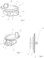
Fig. 1 ; - Fig. 4:
- eine perspektivische Darstellung der Apparatur nach
Fig. 1 ; - Fig. 5:
- eine perspektivische Rückansicht der Apparatur nach
Fig. 1 ; und - Fig. 6:
- eine schematische Darstellung der Einrichtung zur stereoskopischen Wiedergabe von Videoinformationen, sowie eines optischen Aufnahmegerätes bzw. einer Kamera vor einer Abschirmung.
- Die Apparatur zum Strahlungsschutz der Augen umfasst ein Gehäuse 1, das aus einer schalenartigen Fassung 2 besteht, mit einer offenen Rückseite, welche den Kopf einschließlich der Augenpartie und seitlich die Schläfen des Trägers lichtdicht umschließt. Weiterhin ist die schalenartige Fassung 2 an einer Trageeinrichtung 3 zum Aufsetzen auf dem Kopf befestigt und mit einer Nasenauflage 4 zum Positionieren und Abstützen der schalenartigen Fassung 3 auf dem Nasenrücken des Trägers versehen.
- Im vorderen Bereich der schalenartigen Fassung 2, also auf der dem Kopf abgewandten Seite, befindet sich eine im Wesentlichen über deren gesamte Breite reichende frontseitige Öffnung 5 zur Aufnahme einer Abschirmung 6 aus einem für Röntgen- oder ionisierende Strahlung undurchlässigen Material. Diese Abschirmung 5, die leicht bogenförmig verläuft, reduziert die die Augen erreichende Strahlungsdosis von einer Quelle für Röntgenstrahlung auf Werte nahe Null, insbesondere dann, wenn die Abschirmung 6 aus einer Bleiplatte besteht.
- Die Abschirmung 6 kann an Stelle aus Blei, auch aus einem anderen geeigneten Material gefertigt werden, sofern die gewünschte Abschirmung gewährleistet ist. So dass dadurch eine Gewichtsreduzierung erreicht werden kann.
- Als Abschirmung 6 kommt insbesondere eine mindestens die Augenpartie vollkommen abdeckende Bleiplatte mit geringst möglichem Gewicht, oder ein anderes Abschirmungsmaterial für Röntgenstrahlung in Betracht, wobei für die Auswahl des strahlungsundurchlässigen Materials wesentlich ist, dass die das Auge erreichende Strahlungsdosis auf Werte nahe Null reduziert wird.
- Die Abschirmung 5 kann auch den seitlichen Schläfenbereich umfassen, so dass ein noch besserer Strahlungsschutz für die Augen erreicht wird, was insbesondere dann von Vorteil ist, wenn der Träger der Apparatur seinen Kopf zur Seite gedreht hat, so dass die frontseitige Abschirmung 5 nicht mehr in Richtung der Quelle für die Röntgenstrahlung weist. Durch die zusätzliche seitliche Abschirmung kann die Röntgenstrahlung auch nicht ungewollt von der Seite in die Augen einstrahlen.
- Alternativ kann die schalenartige Fassung 2 auch insgesamt aus einem für Röntgenstrahlung undurchlässigem oder kaum durchlässigen Material gefertigt werden.
- Die Trageeinrichtung 3 für das Gehäuse 1 ist ein der Kopfform des Trägers angepasster bzw. sich selbst anpassender Ring 7, an dem das Gehäuse 1 mit der schalenartigen Fassung 2 hängend befestigt ist. Um eine individuelle Anpassung des Ringes 7 an den Kopf des Trägers zu ermöglichen, ist dieser über einen nicht dargestellten Rastmechanismus, o.dgl. im Umfang einstellbar.
- Weiterhin befindet sich am Ring 7, diametral gegenüberliegend zum Gehäuse 1, ein bevorzugt schwenkbar gelagertes Kopfpolster 8, das sich am Hinterkopf abstützt und ein sicheres Tragen der Apparatur ermöglicht.
- Das Kopfpolster 8 kann auch zumindest teilweise als ein Gegengewicht für das mit dem Ring 7 verbundene Gehäuse 1 verwendet werden. Beispielsweise könnte zu diesem Zweck im Kopfpolster 8 ein Batteriefach untergebracht sein, so dass eine gleichmäßigere Druckbelastung des Kopfes durch den Ring 7 erreicht wird.
- Zur besseren Lastverteilung können auch ein oder mehrere am Ring 7 befestigte Tragbänder vorgesehen sein, die sich beim Aufsetzen der Apparatur von oben am Kopf des Trägers anlegen.
- Ergänzend können die Nasenauflage 4 und der Ring 7 zumindest im Kontaktbereich mit dem Kopf, also den Auflagestellen, mit einer Polsterung versehen sein.
- Auf der den Augen des Trägers zugewandten Rückseite der Abschirmung 6 befindet sich wenigstens eine Wiedergabeeinrichtung 9 zur stereoskopischen Wiedergabe von Videoinformationen, die mit einem optischen Aufnahmegerät 10 bzw. einer Kamera gekoppelt ist, die auf der den Augen des Trägers abgewandten Seite der Abschirmung 6 angeordnet ist, wobei die von dem Aufnahmegerät 10 aufgenommenen Bilder und Bildsequenzen unmittelbar und verzögerungsfrei auf die Wiedergabeeinrichtung 9 übertragen werden.
- Diese Anordnung erlaubt es, vor den Augen des Trägers der Apparatur ein dynamisches Abbild zu erzeugen, das dem realen Abbild einer Szene vor dem Auge (zumindest weitgehend) entspricht, wobei ein räumliches Sehen problemlos möglich ist, wobei die die Apparatur erreichende Röntgenstrahlung die Augen des Trägers nicht erreichen kann, so dass ein gefahrloses Arbeiten möglich ist.
- Wiedergabeeinrichtung 9 kann aus jeweils einem vor jedem Auge innerhalb der schalenartigen Fassung 2 positionierten Bildschirm bestehen, der ggf. auch einen runden Umriss haben kann.
- Alternativ kann die Wiedergabeeinrichtung 9 auch aus einem einzigen vor beiden Augen des Trägers befindlichen Bildschirm bestehen, der mit einem Shutter gekoppelt ist, der die Bilder für beide Augen nacheinander erzeugt, so dass für den Träger der Apparatur ein Stereoeindruck entsteht.
- Auch kann die Wiedergabeeinrichtung 9 ein Split-Screen-Bildschirm sein, der für einen Stereoeindruck für jedes Auge ein separates Bild erzeugt.
- In jedem Fall wird dem Träger ein realistisches stereoskopisches Abbild der Vorgänge vor der Apparatur vermittelt, welches dem medizinischen Personal ein sicheres und für die Augen gefahrloses Arbeiten ermöglicht.
- Um den relativ geringen Abstand zwischen Bildschirm und Auge auszugleichen, oder zum Ausgleich einer Fehlsichtigkeit, ist zwischen den Augen des Trägers und dem Bildschirm oder den Bildschirmen jeweils eine Optik 11 zur Fokussierung des angezeigten Bildes auf die Augen angeordnet, wodurch ein ermüdungsfreies Betrachten des Bildschirmes ermöglicht wird.
- Weiterhin ist es im Interesse einer guten stereoskopischen Wiedergabe zweckmäßig, die optischen Achsen der Einzelbildschirme mechanisch durch Verschieben, oder elektronisch durch Verschieben der Abbildungen auf den Einzelbildschirmen, auf den jeweiligen Augenabstand des Trägers einzustellen.
- Das optischen Aufnahmegerät 10 bzw. die Kamera kann eine stereoskopische Kamera sein, die unmittelbar vor der Abschirmung 6 positioniert ist.
- Alternativ können vor der Abschirmung 6 auch zwei in einem Abstand zueinander und nebeneinander angeordnete Einzelkameras vorgesehen sein, deren Abstand zueinander auf den Augenabstand einstellbar sein kann. Damit kann der stereoskopische Eindruck beim Träger der Apparatur auf die individuellen Gegebenheiten angepasst werden.
- Die elektrische Verbindung zwischen der Wiedergabeeinrichtung 9 und dem Aufnahmegerät 9 zur Stromversorgung und Informationsübertragung erfolgt mittels einer geeigneten Umverdrahtung, die um die Abschirmung 6 herumgelegt ist.
- Um ein störlichtfreies Betrachten des Bildschirmes oder der Bildschirme zu gewährleisten, liegt die schalenartige Fassung 2 im Wesentlichen lichtdicht, die Augen des Trägers einschließend, am Kopf an.
- Da auch Spiegelungen oder Lichtreflexe, verursacht durch die Wiedergabeeinrichtung 10, zu vermeiden, sollte das Gehäuse 1 oder zumindest die schalenartige Fassung auf der Innenseite eine entspiegelte oder matte Oberfläche aufweisen, was beispielsweise auch durch eine matte oder mattschwarze Beschichtung erreicht werden kann. Dadurch wird eine weitgehend ermüdungsfreie Benutzung der erfindungsgemäßen Apparatur durch einen Diagnostiker gewährleistet. Zum Schutz vor Beschädigung und Verschmutzung, sowie aus gestalterischen Grünen, ist vor der stereoskopischen Kamera bzw. den Einzelkameras eine glasklar durchsichtige und die schalenartige Fassung 2 nach vorn abschließende Schutzscheibe 12 angeordnet, die mit der schalenartigen Fassung 2 lösbar verbunden sein kann.
- Der besondere Vorteil der erfindungsgemäßen Apparatur ist darin zu sehen, dass die Augenpartie mindestens in Richtung der Quelle der Röntgenstrahlung vollständig mit einem undurchsichtigen, strahlungsundurchlässigen Material abgeschirmt wird, wobei die die Szene vor der Apparatur in Echtzeit von der Wiedergabeeinrichtung 10 zur stereoskopischen Wiedergabe von Videoinformationen auf der Rückseite der Abschirmung 6 wiedergegeben wird.
- Im Interesse einer möglichst leichten und somit ermüdungsfrei zu tragenden Apparatur bestehen sämtliche Bauteile des Gehäuses 1, wie die schalenartige Fassung 2, die Optik 11 und die Schutzscheibe 12, ausgenommen die Abschirmung und die Videoaufnahme- und Wiedergabeeinrichtungen mit zugehöriger Elektronik, aus einem möglichst leichten Kunststoffmaterial.
- Über die Wiedergabeeinrichtung 10 können auch Zusatzinformationen wie Blutdruck oder andere Werte, sowie Bildinformationen aus anderen Untersuchungen, etc. eingeblendet werden.
-
- 1
- Gehäuse
- 2
- schalenartige Fassung
- 3
- Trageeinrichtung
- 4
- Nasenauflage
- 5
- Öffnung
- 6
- Abschirmung
- 7
- Ring
- 8
- Kopfpolster
- 9
- Wiedergabeeinrichtung
- 10
- Aufnahmegerät
- 11
- Optik
- 12
- Schutzscheibe
Claims (18)
- Apparatur zum Strahlungsschutz der Augen, insbesondere der Augenlinsen, von medizinischem Personal, wie Ärzte oder Diagnostiker, vor Röntgen- oder anderer ionisierender Strahlung während medizinischer Untersuchungen, umfassend ein vor der Augenpartie am Kopf positionierbares Gehäuse,wobei das Gehäuse (1) aus einer die Augenpartie und seitlich die Schläfen des Trägers lichtdicht umschließenden schalenartigen Fassung (2) besteht,wobei die schalenartige Fassung (2) einerseits mit einer Trageeinrichtung (3) zum Aufsetzen auf dem Kopf und andererseits mit einer Nasenauflage (4) zum Positionieren auf dem Nasenrücken des Trägers versehen ist,wobei die Trageeinrichtung (3) als ein der Kopfform angepasster bzw. sich selbst anpassender Ring (7) ausgebildet ist, an dem das Gehäuse (1) mit der schalenartigen Fassung (2) hängend befestigt ist und dass am Ring (7) diametral gegenüberliegend zum Gehäuse (1) ein Kopfpolster (8) angeordnet ist, das sich am Hinterkopf abstützt,wobei die schalenartige Fassung (2) mit einer über dessen gesamte Breite reichenden frontseitigen Öffnung (5) versehen ist, in die eine Abschirmung (6) aus einem für Röntgen- oder ionisierende Strahlung undurchlässigen Material eingepasst ist, undwobei auf der den Augen zugewandten Rückseite der Abschirmung (6) innerhalb der schalenförmigen Fassung (2) wenigstens eine Wiedergabeeinrichtung (9) zur stereoskopischen Wiedergabe von Videoinformationen in Echtzeit angeordnet ist, die mit einem optischen Aufnahmegerät bzw. einer Kamera (10) gekoppelt ist, die auf der den Augen des Trägers abgewandten Seite der Abschirmung (6) vor dieser angeordnet ist.
- Apparatur nach Anspruch 1, dadurch gekennzeichnet, dass die Abschirmung (6) aus Blei oder einem anderen geeignetem Material besteht.
- Apparatur nach Anspruch 1 und 2, dadurch gekennzeichnet, dass die Abschirmung den seitlichen Schläfenbereich des Kopfes umfasst.
- Apparatur nach Anspruch 1, dadurch gekennzeichnet, dass die Wiedergabeeinrichtung (9) zur stereoskopischen Wiedergabe von Videoinformationen aus jeweils einem vor jedem Auge angeordneten Bildschirm besteht.
- Apparatur nach Anspruch 1, dadurch gekennzeichnet, dass die Wiedergabeeinrichtung (9) zur stereoskopischen Widergabe von Videoinformationen aus einem einzigen vor beiden Augen des Trägers positionierten Bildschirm besteht.
- Apparatur nach Anspruch 5, dadurch gekennzeichnet, dass der Bildschirm ein Split-Screen-Bildschirm ist, der für jedes Auge für einen Stereoeindruck ein separates Bild erzeugt.
- Apparatur nach Anspruch 5, dadurch gekennzeichnet, dass der Bildschirm mit einem Shutter gekoppelt ist, der die Bilder für beide Augen nacheinander erzeugt, so dass ein Stereoeindruck entsteht.
- Apparatur nach einem der Ansprüche 4 bis 7, dadurch gekennzeichnet, dass zwischen den Augen des Trägers und dem Bildschirm oder den Bildschirmen jeweils eine Optik (11) zur Fokussierung des angezeigten Bildes auf die Augen angeordnet ist.
- Apparatur nach einem der Ansprüche 1 bis 8, dadurch gekennzeichnet, dass das optische Aufnahmegerät bzw. die Kamera (10) eine stereoskopische Kamera ist, die unmittelbar vor der Abschirmung (6) angeordnet ist.
- Apparatur nach einem der Ansprüche 1 bis 8, dadurch gekennzeichnet, dass vor der Abschirmung (6) zwei in einem Abstand zueinander und nebeneinander angeordnete Einzelkameras vorgesehen sind, deren Abstand zueinander auf den Augenabstand einstellbar ist.
- Apparatur nach einem der Ansprüche 1 bis 10, dadurch gekennzeichnet, dass die optischen Achsen der Einzelbildschirme mechanisch durch Verschieben der Einzelbildschirme, oder elektronisch durch Verschieben der Abbilder auf den jeweiligen Augenabstand des Trägers einstellbar sind.
- Apparatur nach einem der Ansprüche 1 bis 11, dadurch gekennzeichnet, dass schalenförmige die Fassung (2) im Wesentlichen lichtdicht, die Augen des Trägers einschließend, am Kopf anliegt.
- Apparatur nach einem der Ansprüche 1 bis 12, dadurch gekennzeichnet, dass vor der stereoskopischen Kamera bzw. den Einzelkameras eine glasklar durchsichtige und die schalenförmige Fassung (2) abschließende Schutzscheibe (12) angeordnet ist.
- Apparatur nach Anspruch 11, dadurch gekennzeichnet, dass der Ring (7) über einen nicht dargestellten Rastmechanismus im Umfang einstellbar ist.
- Apparatur nach Anspruch 11, dadurch gekennzeichnet, dass das Kopfpolster (8) am Ring (7) verschwenkbar gelagert ist.
- Apparatur nach einem der Ansprüche 1 bis 15, dadurch gekennzeichnet, dass die Nasenauflage (4) und der Ring (7) zumindest im Kontaktbereich mit dem Kopf mit einer Polsterung versehen sind.
- Apparatur nach einem der Ansprüche 1 bis 16, dadurch gekennzeichnet, dass sämtliche Bauteile, wie das Gehäuse (1), die schalenartige Fassung (2), die Optik (11) und die Schutzscheibe (12), außer der Abschirmung (6) und der Videoaufnahme- und Wiedergabeeinrichtungen mit zugehöriger Elektronik, aus Kunststoff bestehen.
- Apparatur nach einem der Ansprüche 1 bis 17, dadurch gekennzeichnet, dass das Gehäuse (1), oder zumindest die schalenartige Fassung (2) auf der Innenseite eine entspiegelte oder matte Oberfläche aufweist.
Applications Claiming Priority (2)
| Application Number | Priority Date | Filing Date | Title |
|---|---|---|---|
| DE102016123634 | 2016-12-07 | ||
| PCT/EP2017/081858 WO2018104465A2 (de) | 2016-12-07 | 2017-12-07 | Apparatur zum strahlungsschutz der augen |
Publications (2)
| Publication Number | Publication Date |
|---|---|
| EP3551144A2 EP3551144A2 (de) | 2019-10-16 |
| EP3551144B1 true EP3551144B1 (de) | 2023-08-02 |
Family
ID=61132369
Family Applications (1)
| Application Number | Title | Priority Date | Filing Date |
|---|---|---|---|
| EP17837861.8A Active EP3551144B1 (de) | 2016-12-07 | 2017-12-07 | Apparatur zum strahlungsschutz der augen |
Country Status (7)
| Country | Link |
|---|---|
| US (1) | US11583447B2 (de) |
| EP (1) | EP3551144B1 (de) |
| CN (1) | CN110022804A (de) |
| DK (1) | DK3551144T3 (de) |
| EA (1) | EA035657B1 (de) |
| ES (1) | ES2961503T3 (de) |
| WO (1) | WO2018104465A2 (de) |
Families Citing this family (9)
| Publication number | Priority date | Publication date | Assignee | Title |
|---|---|---|---|---|
| CN109199431B (zh) * | 2018-09-26 | 2024-05-28 | 四川大学华西医院 | 用于病患在x光摄影中头、颈部的防辐射装置 |
| CN110664430A (zh) * | 2019-10-11 | 2020-01-10 | 上海市肺科医院 | 眼睛甲状腺一体化防辐射服 |
| EP4085289A4 (de) * | 2019-12-31 | 2023-08-02 | Resmed Asia Pte. Ltd. | Positionierungs-, stabilisierungs- und schnittstellenstrukturen und system, die dieselbe beinhalten |
| US12256057B2 (en) * | 2019-12-31 | 2025-03-18 | ResMed Asia Pte. Ltd. | Positioning, stabilising, and interfacing structures and system incorporating same |
| US12564236B2 (en) | 2020-03-27 | 2026-03-03 | ResMed Pty Ltd | Positioning and stabilising structure and system incorporating same |
| US12178276B2 (en) | 2020-03-27 | 2024-12-31 | ResMed Pty Ltd | Positioning and stabilising structure and system incorporating same |
| CN111568462A (zh) * | 2020-05-12 | 2020-08-25 | 河南省中医院(河南中医药大学第二附属医院) | 一种放射科用检查护理头部防护组件 |
| EP4202530A4 (de) * | 2020-08-20 | 2024-08-07 | Otos Wing Co., Ltd. | Schweissinformationsbereitstellungsvorrichtung |
| CN118136300B (zh) * | 2024-05-07 | 2024-12-20 | 陕西中医药大学第二附属医院 | 一种碘粒子植入手术用防护面罩 |
Family Cites Families (27)
| Publication number | Priority date | Publication date | Assignee | Title |
|---|---|---|---|---|
| US4603442A (en) * | 1984-12-28 | 1986-08-05 | Barfield Kenneth E | Single lens goggle |
| DE8910235U1 (de) | 1989-08-26 | 1989-10-05 | Fa. Carl Zeiss, 7920 Heidenheim | Laserschutzbrille |
| US5619754A (en) * | 1995-02-13 | 1997-04-15 | Fibre-Metal Products, Co. | Protective cap with reversible headband |
| EP0780783A1 (de) | 1995-12-23 | 1997-06-25 | Deutsche ITT Industries GmbH | Virtual-Reality-Wiedergabesystem mit einer optischen Lageerkennungseinrichtung |
| DE10327017A1 (de) | 2003-06-16 | 2005-01-20 | Jk-Holding Gmbh | Augenschutz gegen Strahlung |
| GB0322551D0 (en) * | 2003-09-26 | 2003-10-29 | Keeler Ltd | Head-mounted instruments |
| US8334899B1 (en) * | 2007-11-01 | 2012-12-18 | Jefferson Science Associates, Llc | Protective laser beam viewing device |
| US8588448B1 (en) * | 2008-09-09 | 2013-11-19 | Energy Telecom, Inc. | Communication eyewear assembly |
| US8023195B2 (en) * | 2008-10-23 | 2011-09-20 | Gentex Corporation | Split laser eye protection system |
| US8569655B2 (en) * | 2009-10-13 | 2013-10-29 | Lincoln Global, Inc. | Welding helmet with integral user interface |
| WO2011106797A1 (en) * | 2010-02-28 | 2011-09-01 | Osterhout Group, Inc. | Projection triggering through an external marker in an augmented reality eyepiece |
| US20110214082A1 (en) * | 2010-02-28 | 2011-09-01 | Osterhout Group, Inc. | Projection triggering through an external marker in an augmented reality eyepiece |
| US8976086B2 (en) * | 2010-12-03 | 2015-03-10 | Esight Corp. | Apparatus and method for a bioptic real time video system |
| US9073138B2 (en) * | 2011-05-16 | 2015-07-07 | Lincoln Global, Inc. | Dual-spectrum digital imaging welding helmet |
| EP2750607B1 (de) * | 2011-09-16 | 2019-05-01 | Koninklijke Philips N.V. | 3d-röntgenbetrachtung im live-modus |
| US9480539B2 (en) * | 2011-11-03 | 2016-11-01 | James Ortlieb | Viewing system and viewing method for assisting user in carrying out surgery by identifying a target image |
| JP5987387B2 (ja) * | 2012-03-22 | 2016-09-07 | ソニー株式会社 | ヘッドマウントディスプレイ及び手術システム |
| FR2992549B1 (fr) * | 2012-06-27 | 2015-07-31 | Commissariat Energie Atomique | Dispositif de protection contre les rayonnements optiques et les projections solides ou liquides |
| KR20160005680A (ko) * | 2013-03-15 | 2016-01-15 | 임미 인크. | 비동공 형성 광 경로를 갖는 헤드마운트 디스플레이 |
| US20140333773A1 (en) * | 2013-05-11 | 2014-11-13 | Randy James Davis | Portable audio/ video mask |
| US9332903B2 (en) * | 2013-09-19 | 2016-05-10 | Gn Otometrics A/S | Headgear for observation of eye movements |
| US9506869B2 (en) * | 2013-10-16 | 2016-11-29 | Tsi, Incorporated | Handheld laser induced breakdown spectroscopy device |
| JP6253763B2 (ja) * | 2014-03-14 | 2017-12-27 | 株式会社ソニー・インタラクティブエンタテインメント | ヘッドマウントディスプレイ |
| WO2015148324A1 (en) * | 2014-03-22 | 2015-10-01 | Radtec Medical Devices, Inc. | Shield for protecting a user from radiation emitted during x-ray imaging |
| US10197816B2 (en) * | 2015-05-26 | 2019-02-05 | Lumenis Ltd. | Laser safety glasses with an improved imaging system |
| EP3235478A1 (de) * | 2016-04-18 | 2017-10-25 | Universität Wien | Schutzbrille |
| US10610179B2 (en) * | 2017-06-05 | 2020-04-07 | Biosense Webster (Israel) Ltd. | Augmented reality goggles having X-ray protection |
-
2017
- 2017-12-07 DK DK17837861.8T patent/DK3551144T3/da active
- 2017-12-07 ES ES17837861T patent/ES2961503T3/es active Active
- 2017-12-07 EA EA201991372A patent/EA035657B1/ru unknown
- 2017-12-07 EP EP17837861.8A patent/EP3551144B1/de active Active
- 2017-12-07 US US16/465,719 patent/US11583447B2/en active Active
- 2017-12-07 WO PCT/EP2017/081858 patent/WO2018104465A2/de not_active Ceased
- 2017-12-07 CN CN201780074745.4A patent/CN110022804A/zh active Pending
Also Published As
| Publication number | Publication date |
|---|---|
| US11583447B2 (en) | 2023-02-21 |
| EP3551144A2 (de) | 2019-10-16 |
| US20190290491A1 (en) | 2019-09-26 |
| WO2018104465A3 (de) | 2018-08-02 |
| CN110022804A (zh) | 2019-07-16 |
| DK3551144T3 (da) | 2023-11-06 |
| EA035657B1 (ru) | 2020-07-22 |
| EA201991372A1 (ru) | 2019-11-29 |
| ES2961503T3 (es) | 2024-03-12 |
| WO2018104465A2 (de) | 2018-06-14 |
Similar Documents
| Publication | Publication Date | Title |
|---|---|---|
| EP3551144B1 (de) | Apparatur zum strahlungsschutz der augen | |
| DE69113287T2 (de) | Wiedergabeeinrichtung in Brillenform zur direkten Wiedergabe auf der Netzhaut. | |
| DE69413828T2 (de) | Bildanzeigevorrichtung | |
| DE10251933B4 (de) | Aufnahmevorrichtung für die kopfgestützte Bilderfassung und Verfahren zur Steuerung der Aufnahmevorrichtung | |
| DE112016004662T5 (de) | Wearable-Display mit einstellbarer Pupillendistanz | |
| DE2843661A1 (de) | Tragbares sichtgeraet | |
| DE102015219859B4 (de) | Vorrichtung und Verfahren für die AR-Darstellung | |
| WO2018028759A1 (de) | Laserschutzbrille zur vollständigen, wellenlängenunabhängigen abschirmung von hochleistungslaserstrahlen | |
| DE60133693T2 (de) | Stereoskopische Bildanzeigevorrichtung | |
| DE202012000167U1 (de) | Mobiles Videozentriersystem zur Bestimmung von Zentrierdaten für Brillengläser | |
| DE3628458A1 (de) | Vorrichtung zum raeumlichen sehen dreidimensionaler fernsehbilder | |
| DE102014017534A1 (de) | Anzeigevorrichtung, die auf den Kopf eines Benutzers aufsetzbar ist | |
| DE3623206A1 (de) | Nachtsichtgeraet | |
| DE102008053395A1 (de) | Verfahren und Einrichtung zur fotografischen Bilderfassung des Gesichtsfelds einer Person | |
| DE202007016525U1 (de) | Weste für audiovisuelles System | |
| DE102005014759A1 (de) | Anzeigevorrichtung und Anzeigeverfahren | |
| DE1804431A1 (de) | Beobachtungs- oder Betrachtungsbrille und Navigationsvefahren fuer ein Flugzeug | |
| EP1488768B1 (de) | Augenschutz gegen Strahlung | |
| DE102014017835A1 (de) | Laserschutzbrille mit 3D-Video-Einblendung | |
| DE2820878A1 (de) | Kamera-visieroptik | |
| WO2004025353A1 (de) | Am kopf tragbare anzeigevorrichtung bei verbessertem gesichtsfeld | |
| DE102004040148A1 (de) | Lichtschutzbrille | |
| DE2838547A1 (de) | Tragbarer rueckspiegel | |
| DE2822935C2 (de) | Einäugige Spiegelreflex-Kamera mit einem Sucher und mit einem Objektiv langer Brennweite | |
| DE202018002511U1 (de) | Umhausung für ein elektronisches Gerät |
Legal Events
| Date | Code | Title | Description |
|---|---|---|---|
| STAA | Information on the status of an ep patent application or granted ep patent |
Free format text: STATUS: UNKNOWN |
|
| STAA | Information on the status of an ep patent application or granted ep patent |
Free format text: STATUS: THE INTERNATIONAL PUBLICATION HAS BEEN MADE |
|
| PUAI | Public reference made under article 153(3) epc to a published international application that has entered the european phase |
Free format text: ORIGINAL CODE: 0009012 |
|
| STAA | Information on the status of an ep patent application or granted ep patent |
Free format text: STATUS: REQUEST FOR EXAMINATION WAS MADE |
|
| 17P | Request for examination filed |
Effective date: 20190705 |
|
| AK | Designated contracting states |
Kind code of ref document: A2 Designated state(s): AL AT BE BG CH CY CZ DE DK EE ES FI FR GB GR HR HU IE IS IT LI LT LU LV MC MK MT NL NO PL PT RO RS SE SI SK SM TR |
|
| AX | Request for extension of the european patent |
Extension state: BA ME |
|
| DAV | Request for validation of the european patent (deleted) | ||
| DAX | Request for extension of the european patent (deleted) | ||
| STAA | Information on the status of an ep patent application or granted ep patent |
Free format text: STATUS: EXAMINATION IS IN PROGRESS |
|
| 17Q | First examination report despatched |
Effective date: 20210625 |
|
| GRAP | Despatch of communication of intention to grant a patent |
Free format text: ORIGINAL CODE: EPIDOSNIGR1 |
|
| STAA | Information on the status of an ep patent application or granted ep patent |
Free format text: STATUS: GRANT OF PATENT IS INTENDED |
|
| INTG | Intention to grant announced |
Effective date: 20230213 |
|
| GRAS | Grant fee paid |
Free format text: ORIGINAL CODE: EPIDOSNIGR3 |
|
| GRAA | (expected) grant |
Free format text: ORIGINAL CODE: 0009210 |
|
| STAA | Information on the status of an ep patent application or granted ep patent |
Free format text: STATUS: THE PATENT HAS BEEN GRANTED |
|
| AK | Designated contracting states |
Kind code of ref document: B1 Designated state(s): AL AT BE BG CH CY CZ DE DK EE ES FI FR GB GR HR HU IE IS IT LI LT LU LV MC MK MT NL NO PL PT RO RS SE SI SK SM TR |
|
| REG | Reference to a national code |
Ref country code: GB Ref legal event code: FG4D Free format text: NOT ENGLISH |
|
| REG | Reference to a national code |
Ref country code: CH Ref legal event code: EP |
|
| REG | Reference to a national code |
Ref country code: DE Ref legal event code: R096 Ref document number: 502017015157 Country of ref document: DE |
|
| REG | Reference to a national code |
Ref country code: IE Ref legal event code: FG4D Free format text: LANGUAGE OF EP DOCUMENT: GERMAN |
|
| REG | Reference to a national code |
Ref country code: CH Ref legal event code: PK Free format text: BERICHTIGUNGEN |
|
| REG | Reference to a national code |
Ref country code: DE Ref legal event code: R081 Ref document number: 502017015157 Country of ref document: DE Owner name: VACUTEC MESSTECHNIK GMBH, DE Free format text: FORMER OWNER: WOERMANN, BERND, 01328 DRESDEN, DE |
|
| RAP2 | Party data changed (patent owner data changed or rights of a patent transferred) |
Owner name: VACUTEC MESSTECHNIK GMBH |
|
| RIN2 | Information on inventor provided after grant (corrected) |
Inventor name: WOERMANN, BERND |
|
| REG | Reference to a national code |
Ref country code: DK Ref legal event code: T3 Effective date: 20231101 |
|
| REG | Reference to a national code |
Ref country code: NL Ref legal event code: FP |
|
| REG | Reference to a national code |
Ref country code: SE Ref legal event code: TRGR |
|
| REG | Reference to a national code |
Ref country code: LT Ref legal event code: MG9D |
|
| PG25 | Lapsed in a contracting state [announced via postgrant information from national office to epo] |
Ref country code: GR Free format text: LAPSE BECAUSE OF FAILURE TO SUBMIT A TRANSLATION OF THE DESCRIPTION OR TO PAY THE FEE WITHIN THE PRESCRIBED TIME-LIMIT Effective date: 20231103 |
|
| PG25 | Lapsed in a contracting state [announced via postgrant information from national office to epo] |
Ref country code: IS Free format text: LAPSE BECAUSE OF FAILURE TO SUBMIT A TRANSLATION OF THE DESCRIPTION OR TO PAY THE FEE WITHIN THE PRESCRIBED TIME-LIMIT Effective date: 20231202 |
|
| PG25 | Lapsed in a contracting state [announced via postgrant information from national office to epo] |
Ref country code: RS Free format text: LAPSE BECAUSE OF FAILURE TO SUBMIT A TRANSLATION OF THE DESCRIPTION OR TO PAY THE FEE WITHIN THE PRESCRIBED TIME-LIMIT Effective date: 20230802 Ref country code: PT Free format text: LAPSE BECAUSE OF FAILURE TO SUBMIT A TRANSLATION OF THE DESCRIPTION OR TO PAY THE FEE WITHIN THE PRESCRIBED TIME-LIMIT Effective date: 20231204 Ref country code: NO Free format text: LAPSE BECAUSE OF FAILURE TO SUBMIT A TRANSLATION OF THE DESCRIPTION OR TO PAY THE FEE WITHIN THE PRESCRIBED TIME-LIMIT Effective date: 20231102 Ref country code: LV Free format text: LAPSE BECAUSE OF FAILURE TO SUBMIT A TRANSLATION OF THE DESCRIPTION OR TO PAY THE FEE WITHIN THE PRESCRIBED TIME-LIMIT Effective date: 20230802 Ref country code: LT Free format text: LAPSE BECAUSE OF FAILURE TO SUBMIT A TRANSLATION OF THE DESCRIPTION OR TO PAY THE FEE WITHIN THE PRESCRIBED TIME-LIMIT Effective date: 20230802 Ref country code: IS Free format text: LAPSE BECAUSE OF FAILURE TO SUBMIT A TRANSLATION OF THE DESCRIPTION OR TO PAY THE FEE WITHIN THE PRESCRIBED TIME-LIMIT Effective date: 20231202 Ref country code: HR Free format text: LAPSE BECAUSE OF FAILURE TO SUBMIT A TRANSLATION OF THE DESCRIPTION OR TO PAY THE FEE WITHIN THE PRESCRIBED TIME-LIMIT Effective date: 20230802 Ref country code: GR Free format text: LAPSE BECAUSE OF FAILURE TO SUBMIT A TRANSLATION OF THE DESCRIPTION OR TO PAY THE FEE WITHIN THE PRESCRIBED TIME-LIMIT Effective date: 20231103 Ref country code: FI Free format text: LAPSE BECAUSE OF FAILURE TO SUBMIT A TRANSLATION OF THE DESCRIPTION OR TO PAY THE FEE WITHIN THE PRESCRIBED TIME-LIMIT Effective date: 20230802 |
|
| REG | Reference to a national code |
Ref country code: GB Ref legal event code: 732E Free format text: REGISTERED BETWEEN 20240118 AND 20240124 |
|
| PG25 | Lapsed in a contracting state [announced via postgrant information from national office to epo] |
Ref country code: PL Free format text: LAPSE BECAUSE OF FAILURE TO SUBMIT A TRANSLATION OF THE DESCRIPTION OR TO PAY THE FEE WITHIN THE PRESCRIBED TIME-LIMIT Effective date: 20230802 |
|
| REG | Reference to a national code |
Ref country code: ES Ref legal event code: FG2A Ref document number: 2961503 Country of ref document: ES Kind code of ref document: T3 Effective date: 20240312 |
|
| PG25 | Lapsed in a contracting state [announced via postgrant information from national office to epo] |
Ref country code: SM Free format text: LAPSE BECAUSE OF FAILURE TO SUBMIT A TRANSLATION OF THE DESCRIPTION OR TO PAY THE FEE WITHIN THE PRESCRIBED TIME-LIMIT Effective date: 20230802 Ref country code: RO Free format text: LAPSE BECAUSE OF FAILURE TO SUBMIT A TRANSLATION OF THE DESCRIPTION OR TO PAY THE FEE WITHIN THE PRESCRIBED TIME-LIMIT Effective date: 20230802 Ref country code: EE Free format text: LAPSE BECAUSE OF FAILURE TO SUBMIT A TRANSLATION OF THE DESCRIPTION OR TO PAY THE FEE WITHIN THE PRESCRIBED TIME-LIMIT Effective date: 20230802 Ref country code: CZ Free format text: LAPSE BECAUSE OF FAILURE TO SUBMIT A TRANSLATION OF THE DESCRIPTION OR TO PAY THE FEE WITHIN THE PRESCRIBED TIME-LIMIT Effective date: 20230802 Ref country code: SK Free format text: LAPSE BECAUSE OF FAILURE TO SUBMIT A TRANSLATION OF THE DESCRIPTION OR TO PAY THE FEE WITHIN THE PRESCRIBED TIME-LIMIT Effective date: 20230802 |
|
| REG | Reference to a national code |
Ref country code: DE Ref legal event code: R097 Ref document number: 502017015157 Country of ref document: DE |
|
| PLBE | No opposition filed within time limit |
Free format text: ORIGINAL CODE: 0009261 |
|
| STAA | Information on the status of an ep patent application or granted ep patent |
Free format text: STATUS: NO OPPOSITION FILED WITHIN TIME LIMIT |
|
| 26N | No opposition filed |
Effective date: 20240503 |
|
| REG | Reference to a national code |
Ref country code: AT Ref legal event code: PC Ref document number: 1593834 Country of ref document: AT Kind code of ref document: T Owner name: VACUTEC MESSTECHNIK GMBH, DE Effective date: 20240517 |
|
| PG25 | Lapsed in a contracting state [announced via postgrant information from national office to epo] |
Ref country code: SI Free format text: LAPSE BECAUSE OF FAILURE TO SUBMIT A TRANSLATION OF THE DESCRIPTION OR TO PAY THE FEE WITHIN THE PRESCRIBED TIME-LIMIT Effective date: 20230802 |
|
| PG25 | Lapsed in a contracting state [announced via postgrant information from national office to epo] |
Ref country code: LU Free format text: LAPSE BECAUSE OF NON-PAYMENT OF DUE FEES Effective date: 20231207 |
|
| PG25 | Lapsed in a contracting state [announced via postgrant information from national office to epo] |
Ref country code: MC Free format text: LAPSE BECAUSE OF FAILURE TO SUBMIT A TRANSLATION OF THE DESCRIPTION OR TO PAY THE FEE WITHIN THE PRESCRIBED TIME-LIMIT Effective date: 20230802 |
|
| REG | Reference to a national code |
Ref country code: BE Ref legal event code: MM Effective date: 20231231 |
|
| PG25 | Lapsed in a contracting state [announced via postgrant information from national office to epo] |
Ref country code: MC Free format text: LAPSE BECAUSE OF FAILURE TO SUBMIT A TRANSLATION OF THE DESCRIPTION OR TO PAY THE FEE WITHIN THE PRESCRIBED TIME-LIMIT Effective date: 20230802 Ref country code: LU Free format text: LAPSE BECAUSE OF NON-PAYMENT OF DUE FEES Effective date: 20231207 |
|
| REG | Reference to a national code |
Ref country code: IE Ref legal event code: MM4A |
|
| PG25 | Lapsed in a contracting state [announced via postgrant information from national office to epo] |
Ref country code: IE Free format text: LAPSE BECAUSE OF NON-PAYMENT OF DUE FEES Effective date: 20231207 |
|
| PG25 | Lapsed in a contracting state [announced via postgrant information from national office to epo] |
Ref country code: BE Free format text: LAPSE BECAUSE OF NON-PAYMENT OF DUE FEES Effective date: 20231231 |
|
| PG25 | Lapsed in a contracting state [announced via postgrant information from national office to epo] |
Ref country code: IE Free format text: LAPSE BECAUSE OF NON-PAYMENT OF DUE FEES Effective date: 20231207 Ref country code: BE Free format text: LAPSE BECAUSE OF NON-PAYMENT OF DUE FEES Effective date: 20231231 |
|
| PG25 | Lapsed in a contracting state [announced via postgrant information from national office to epo] |
Ref country code: BG Free format text: LAPSE BECAUSE OF FAILURE TO SUBMIT A TRANSLATION OF THE DESCRIPTION OR TO PAY THE FEE WITHIN THE PRESCRIBED TIME-LIMIT Effective date: 20230802 |
|
| PG25 | Lapsed in a contracting state [announced via postgrant information from national office to epo] |
Ref country code: BG Free format text: LAPSE BECAUSE OF FAILURE TO SUBMIT A TRANSLATION OF THE DESCRIPTION OR TO PAY THE FEE WITHIN THE PRESCRIBED TIME-LIMIT Effective date: 20230802 |
|
| PG25 | Lapsed in a contracting state [announced via postgrant information from national office to epo] |
Ref country code: CY Free format text: LAPSE BECAUSE OF FAILURE TO SUBMIT A TRANSLATION OF THE DESCRIPTION OR TO PAY THE FEE WITHIN THE PRESCRIBED TIME-LIMIT; INVALID AB INITIO Effective date: 20171207 |
|
| PG25 | Lapsed in a contracting state [announced via postgrant information from national office to epo] |
Ref country code: HU Free format text: LAPSE BECAUSE OF FAILURE TO SUBMIT A TRANSLATION OF THE DESCRIPTION OR TO PAY THE FEE WITHIN THE PRESCRIBED TIME-LIMIT; INVALID AB INITIO Effective date: 20171207 |
|
| REG | Reference to a national code |
Ref country code: CH Ref legal event code: U11 Free format text: ST27 STATUS EVENT CODE: U-0-0-U10-U11 (AS PROVIDED BY THE NATIONAL OFFICE) Effective date: 20260101 |
|
| PGFP | Annual fee paid to national office [announced via postgrant information from national office to epo] |
Ref country code: DE Payment date: 20251209 Year of fee payment: 9 |
|
| PGFP | Annual fee paid to national office [announced via postgrant information from national office to epo] |
Ref country code: GB Payment date: 20251218 Year of fee payment: 9 |
|
| PGFP | Annual fee paid to national office [announced via postgrant information from national office to epo] |
Ref country code: AT Payment date: 20251215 Year of fee payment: 9 |
|
| PGFP | Annual fee paid to national office [announced via postgrant information from national office to epo] |
Ref country code: DK Payment date: 20251217 Year of fee payment: 9 |
|
| PGFP | Annual fee paid to national office [announced via postgrant information from national office to epo] |
Ref country code: NL Payment date: 20251217 Year of fee payment: 9 Ref country code: FR Payment date: 20251217 Year of fee payment: 9 |
|
| PGFP | Annual fee paid to national office [announced via postgrant information from national office to epo] |
Ref country code: TR Payment date: 20251231 Year of fee payment: 9 |
|
| PGFP | Annual fee paid to national office [announced via postgrant information from national office to epo] |
Ref country code: SE Payment date: 20251217 Year of fee payment: 9 |
|
| PGFP | Annual fee paid to national office [announced via postgrant information from national office to epo] |
Ref country code: ES Payment date: 20260119 Year of fee payment: 9 |
|
| PGFP | Annual fee paid to national office [announced via postgrant information from national office to epo] |
Ref country code: IT Payment date: 20251231 Year of fee payment: 9 |
|
| PGFP | Annual fee paid to national office [announced via postgrant information from national office to epo] |
Ref country code: CH Payment date: 20260101 Year of fee payment: 9 |