EP3551079B1 - System zur automatisierten flüssigkeitsreaktionsmessung - Google Patents
System zur automatisierten flüssigkeitsreaktionsmessung Download PDFInfo
- Publication number
- EP3551079B1 EP3551079B1 EP17877429.5A EP17877429A EP3551079B1 EP 3551079 B1 EP3551079 B1 EP 3551079B1 EP 17877429 A EP17877429 A EP 17877429A EP 3551079 B1 EP3551079 B1 EP 3551079B1
- Authority
- EP
- European Patent Office
- Prior art keywords
- transducer
- ultrasound
- ultrasonic waves
- vessel
- signal
- Prior art date
- Legal status (The legal status is an assumption and is not a legal conclusion. Google has not performed a legal analysis and makes no representation as to the accuracy of the status listed.)
- Active
Links
Images


Classifications
-
- A—HUMAN NECESSITIES
- A61—MEDICAL OR VETERINARY SCIENCE; HYGIENE
- A61B—DIAGNOSIS; SURGERY; IDENTIFICATION
- A61B8/00—Diagnosis using ultrasonic, sonic or infrasonic waves
- A61B8/06—Measuring blood flow
-
- A—HUMAN NECESSITIES
- A61—MEDICAL OR VETERINARY SCIENCE; HYGIENE
- A61B—DIAGNOSIS; SURGERY; IDENTIFICATION
- A61B5/00—Measuring for diagnostic purposes; Identification of persons
- A61B5/02—Detecting, measuring or recording for evaluating the cardiovascular system, e.g. pulse, heart rate, blood pressure or blood flow
- A61B5/026—Measuring blood flow
-
- A—HUMAN NECESSITIES
- A61—MEDICAL OR VETERINARY SCIENCE; HYGIENE
- A61B—DIAGNOSIS; SURGERY; IDENTIFICATION
- A61B8/00—Diagnosis using ultrasonic, sonic or infrasonic waves
- A61B8/02—Measuring pulse or heart rate
-
- A—HUMAN NECESSITIES
- A61—MEDICAL OR VETERINARY SCIENCE; HYGIENE
- A61B—DIAGNOSIS; SURGERY; IDENTIFICATION
- A61B8/00—Diagnosis using ultrasonic, sonic or infrasonic waves
- A61B8/08—Clinical applications
- A61B8/0891—Clinical applications for diagnosis of blood vessels
-
- A—HUMAN NECESSITIES
- A61—MEDICAL OR VETERINARY SCIENCE; HYGIENE
- A61B—DIAGNOSIS; SURGERY; IDENTIFICATION
- A61B8/00—Diagnosis using ultrasonic, sonic or infrasonic waves
- A61B8/42—Details of probe positioning or probe attachment to the patient
- A61B8/4209—Details of probe positioning or probe attachment to the patient by using holders, e.g. positioning frames
- A61B8/4227—Details of probe positioning or probe attachment to the patient by using holders, e.g. positioning frames characterised by straps, belts, cuffs or braces
-
- A—HUMAN NECESSITIES
- A61—MEDICAL OR VETERINARY SCIENCE; HYGIENE
- A61B—DIAGNOSIS; SURGERY; IDENTIFICATION
- A61B8/00—Diagnosis using ultrasonic, sonic or infrasonic waves
- A61B8/42—Details of probe positioning or probe attachment to the patient
- A61B8/4209—Details of probe positioning or probe attachment to the patient by using holders, e.g. positioning frames
- A61B8/4236—Details of probe positioning or probe attachment to the patient by using holders, e.g. positioning frames characterised by adhesive patches
-
- A—HUMAN NECESSITIES
- A61—MEDICAL OR VETERINARY SCIENCE; HYGIENE
- A61B—DIAGNOSIS; SURGERY; IDENTIFICATION
- A61B8/00—Diagnosis using ultrasonic, sonic or infrasonic waves
- A61B8/42—Details of probe positioning or probe attachment to the patient
- A61B8/4272—Details of probe positioning or probe attachment to the patient involving the acoustic interface between the transducer and the tissue
- A61B8/4281—Details of probe positioning or probe attachment to the patient involving the acoustic interface between the transducer and the tissue characterised by sound-transmitting media or devices for coupling the transducer to the tissue
-
- A—HUMAN NECESSITIES
- A61—MEDICAL OR VETERINARY SCIENCE; HYGIENE
- A61B—DIAGNOSIS; SURGERY; IDENTIFICATION
- A61B8/00—Diagnosis using ultrasonic, sonic or infrasonic waves
- A61B8/44—Constructional features of the ultrasonic, sonic or infrasonic diagnostic device
- A61B8/4427—Device being portable or laptop-like
-
- A—HUMAN NECESSITIES
- A61—MEDICAL OR VETERINARY SCIENCE; HYGIENE
- A61B—DIAGNOSIS; SURGERY; IDENTIFICATION
- A61B8/00—Diagnosis using ultrasonic, sonic or infrasonic waves
- A61B8/44—Constructional features of the ultrasonic, sonic or infrasonic diagnostic device
- A61B8/4444—Constructional features of the ultrasonic, sonic or infrasonic diagnostic device related to the probe
- A61B8/4455—Features of the external shape of the probe, e.g. ergonomic aspects
-
- A—HUMAN NECESSITIES
- A61—MEDICAL OR VETERINARY SCIENCE; HYGIENE
- A61B—DIAGNOSIS; SURGERY; IDENTIFICATION
- A61B8/00—Diagnosis using ultrasonic, sonic or infrasonic waves
- A61B8/44—Constructional features of the ultrasonic, sonic or infrasonic diagnostic device
- A61B8/4477—Constructional features of the ultrasonic, sonic or infrasonic diagnostic device using several separate ultrasound transducers or probes
-
- A—HUMAN NECESSITIES
- A61—MEDICAL OR VETERINARY SCIENCE; HYGIENE
- A61B—DIAGNOSIS; SURGERY; IDENTIFICATION
- A61B8/00—Diagnosis using ultrasonic, sonic or infrasonic waves
- A61B8/44—Constructional features of the ultrasonic, sonic or infrasonic diagnostic device
- A61B8/4483—Constructional features of the ultrasonic, sonic or infrasonic diagnostic device characterised by features of the ultrasound transducer
- A61B8/4494—Constructional features of the ultrasonic, sonic or infrasonic diagnostic device characterised by features of the ultrasound transducer characterised by the arrangement of the transducer elements
-
- A—HUMAN NECESSITIES
- A61—MEDICAL OR VETERINARY SCIENCE; HYGIENE
- A61B—DIAGNOSIS; SURGERY; IDENTIFICATION
- A61B8/00—Diagnosis using ultrasonic, sonic or infrasonic waves
- A61B8/46—Ultrasonic, sonic or infrasonic diagnostic devices with special arrangements for interfacing with the operator or the patient
- A61B8/461—Displaying means of special interest
- A61B8/462—Displaying means of special interest characterised by constructional features of the display
-
- A—HUMAN NECESSITIES
- A61—MEDICAL OR VETERINARY SCIENCE; HYGIENE
- A61B—DIAGNOSIS; SURGERY; IDENTIFICATION
- A61B8/00—Diagnosis using ultrasonic, sonic or infrasonic waves
- A61B8/46—Ultrasonic, sonic or infrasonic diagnostic devices with special arrangements for interfacing with the operator or the patient
- A61B8/461—Displaying means of special interest
- A61B8/463—Displaying means of special interest characterised by displaying multiple images or images and diagnostic data on one display
-
- A—HUMAN NECESSITIES
- A61—MEDICAL OR VETERINARY SCIENCE; HYGIENE
- A61B—DIAGNOSIS; SURGERY; IDENTIFICATION
- A61B8/00—Diagnosis using ultrasonic, sonic or infrasonic waves
- A61B8/46—Ultrasonic, sonic or infrasonic diagnostic devices with special arrangements for interfacing with the operator or the patient
- A61B8/461—Displaying means of special interest
- A61B8/465—Displaying means of special interest adapted to display user selection data, e.g. icons or menus
-
- A—HUMAN NECESSITIES
- A61—MEDICAL OR VETERINARY SCIENCE; HYGIENE
- A61B—DIAGNOSIS; SURGERY; IDENTIFICATION
- A61B8/00—Diagnosis using ultrasonic, sonic or infrasonic waves
- A61B8/48—Diagnostic techniques
- A61B8/488—Diagnostic techniques involving Doppler signals
-
- A—HUMAN NECESSITIES
- A61—MEDICAL OR VETERINARY SCIENCE; HYGIENE
- A61B—DIAGNOSIS; SURGERY; IDENTIFICATION
- A61B8/00—Diagnosis using ultrasonic, sonic or infrasonic waves
- A61B8/52—Devices using data or image processing specially adapted for diagnosis using ultrasonic, sonic or infrasonic waves
- A61B8/5215—Devices using data or image processing specially adapted for diagnosis using ultrasonic, sonic or infrasonic waves involving processing of medical diagnostic data
- A61B8/5223—Devices using data or image processing specially adapted for diagnosis using ultrasonic, sonic or infrasonic waves involving processing of medical diagnostic data for extracting a diagnostic or physiological parameter from medical diagnostic data
-
- A—HUMAN NECESSITIES
- A61—MEDICAL OR VETERINARY SCIENCE; HYGIENE
- A61B—DIAGNOSIS; SURGERY; IDENTIFICATION
- A61B8/00—Diagnosis using ultrasonic, sonic or infrasonic waves
- A61B8/52—Devices using data or image processing specially adapted for diagnosis using ultrasonic, sonic or infrasonic waves
- A61B8/5215—Devices using data or image processing specially adapted for diagnosis using ultrasonic, sonic or infrasonic waves involving processing of medical diagnostic data
- A61B8/5238—Devices using data or image processing specially adapted for diagnosis using ultrasonic, sonic or infrasonic waves involving processing of medical diagnostic data for combining image data of patient, e.g. merging several images from different acquisition modes into one image
- A61B8/5246—Devices using data or image processing specially adapted for diagnosis using ultrasonic, sonic or infrasonic waves involving processing of medical diagnostic data for combining image data of patient, e.g. merging several images from different acquisition modes into one image combining images from the same or different imaging techniques, e.g. color Doppler and B-mode
-
- A—HUMAN NECESSITIES
- A61—MEDICAL OR VETERINARY SCIENCE; HYGIENE
- A61B—DIAGNOSIS; SURGERY; IDENTIFICATION
- A61B8/00—Diagnosis using ultrasonic, sonic or infrasonic waves
- A61B8/56—Details of data transmission or power supply
-
- A—HUMAN NECESSITIES
- A61—MEDICAL OR VETERINARY SCIENCE; HYGIENE
- A61B—DIAGNOSIS; SURGERY; IDENTIFICATION
- A61B8/00—Diagnosis using ultrasonic, sonic or infrasonic waves
- A61B8/56—Details of data transmission or power supply
- A61B8/565—Details of data transmission or power supply involving data transmission via a network
-
- A—HUMAN NECESSITIES
- A61—MEDICAL OR VETERINARY SCIENCE; HYGIENE
- A61H—PHYSICAL THERAPY APPARATUS, e.g. DEVICES FOR LOCATING OR STIMULATING REFLEX POINTS IN THE BODY; ARTIFICIAL RESPIRATION; MASSAGE; BATHING DEVICES FOR SPECIAL THERAPEUTIC OR HYGIENIC PURPOSES OR SPECIFIC PARTS OF THE BODY
- A61H31/00—Artificial respiration by a force applied to the chest; Heart stimulation, e.g. heart massage
- A61H31/004—Heart stimulation
- A61H31/005—Heart stimulation with feedback for the user
-
- G—PHYSICS
- G16—INFORMATION AND COMMUNICATION TECHNOLOGY [ICT] SPECIALLY ADAPTED FOR SPECIFIC APPLICATION FIELDS
- G16H—HEALTHCARE INFORMATICS, i.e. INFORMATION AND COMMUNICATION TECHNOLOGY [ICT] SPECIALLY ADAPTED FOR THE HANDLING OR PROCESSING OF MEDICAL OR HEALTHCARE DATA
- G16H50/00—ICT specially adapted for medical diagnosis, medical simulation or medical data mining; ICT specially adapted for detecting, monitoring or modelling epidemics or pandemics
- G16H50/30—ICT specially adapted for medical diagnosis, medical simulation or medical data mining; ICT specially adapted for detecting, monitoring or modelling epidemics or pandemics for calculating health indices; for individual health risk assessment
-
- A—HUMAN NECESSITIES
- A61—MEDICAL OR VETERINARY SCIENCE; HYGIENE
- A61B—DIAGNOSIS; SURGERY; IDENTIFICATION
- A61B2560/00—Constructional details of operational features of apparatus; Accessories for medical measuring apparatus
- A61B2560/02—Operational features
- A61B2560/0204—Operational features of power management
- A61B2560/0214—Operational features of power management of power generation or supply
-
- A—HUMAN NECESSITIES
- A61—MEDICAL OR VETERINARY SCIENCE; HYGIENE
- A61B—DIAGNOSIS; SURGERY; IDENTIFICATION
- A61B2560/00—Constructional details of operational features of apparatus; Accessories for medical measuring apparatus
- A61B2560/04—Constructional details of apparatus
- A61B2560/0462—Apparatus with built-in sensors
-
- A—HUMAN NECESSITIES
- A61—MEDICAL OR VETERINARY SCIENCE; HYGIENE
- A61B—DIAGNOSIS; SURGERY; IDENTIFICATION
- A61B2560/00—Constructional details of operational features of apparatus; Accessories for medical measuring apparatus
- A61B2560/04—Constructional details of apparatus
- A61B2560/0475—Special features of memory means, e.g. removable memory cards
-
- A—HUMAN NECESSITIES
- A61—MEDICAL OR VETERINARY SCIENCE; HYGIENE
- A61B—DIAGNOSIS; SURGERY; IDENTIFICATION
- A61B5/00—Measuring for diagnostic purposes; Identification of persons
- A61B5/74—Details of notification to user or communication with user or patient; User input means
- A61B5/742—Details of notification to user or communication with user or patient; User input means using visual displays
-
- A—HUMAN NECESSITIES
- A61—MEDICAL OR VETERINARY SCIENCE; HYGIENE
- A61B—DIAGNOSIS; SURGERY; IDENTIFICATION
- A61B8/00—Diagnosis using ultrasonic, sonic or infrasonic waves
- A61B8/06—Measuring blood flow
- A61B8/065—Measuring blood flow to determine blood output from the heart
-
- A—HUMAN NECESSITIES
- A61—MEDICAL OR VETERINARY SCIENCE; HYGIENE
- A61B—DIAGNOSIS; SURGERY; IDENTIFICATION
- A61B8/00—Diagnosis using ultrasonic, sonic or infrasonic waves
- A61B8/44—Constructional features of the ultrasonic, sonic or infrasonic diagnostic device
- A61B8/4405—Device being mounted on a trolley
-
- A—HUMAN NECESSITIES
- A61—MEDICAL OR VETERINARY SCIENCE; HYGIENE
- A61H—PHYSICAL THERAPY APPARATUS, e.g. DEVICES FOR LOCATING OR STIMULATING REFLEX POINTS IN THE BODY; ARTIFICIAL RESPIRATION; MASSAGE; BATHING DEVICES FOR SPECIAL THERAPEUTIC OR HYGIENIC PURPOSES OR SPECIFIC PARTS OF THE BODY
- A61H2201/00—Characteristics of apparatus not provided for in the preceding codes
- A61H2201/16—Physical interface with patient
- A61H2201/1602—Physical interface with patient kind of interface, e.g. head rest, knee support or lumbar support
- A61H2201/1609—Neck
-
- A—HUMAN NECESSITIES
- A61—MEDICAL OR VETERINARY SCIENCE; HYGIENE
- A61H—PHYSICAL THERAPY APPARATUS, e.g. DEVICES FOR LOCATING OR STIMULATING REFLEX POINTS IN THE BODY; ARTIFICIAL RESPIRATION; MASSAGE; BATHING DEVICES FOR SPECIAL THERAPEUTIC OR HYGIENIC PURPOSES OR SPECIFIC PARTS OF THE BODY
- A61H2201/00—Characteristics of apparatus not provided for in the preceding codes
- A61H2201/16—Physical interface with patient
- A61H2201/1683—Surface of interface
- A61H2201/1688—Surface of interface disposable
-
- A—HUMAN NECESSITIES
- A61—MEDICAL OR VETERINARY SCIENCE; HYGIENE
- A61H—PHYSICAL THERAPY APPARATUS, e.g. DEVICES FOR LOCATING OR STIMULATING REFLEX POINTS IN THE BODY; ARTIFICIAL RESPIRATION; MASSAGE; BATHING DEVICES FOR SPECIAL THERAPEUTIC OR HYGIENIC PURPOSES OR SPECIFIC PARTS OF THE BODY
- A61H2201/00—Characteristics of apparatus not provided for in the preceding codes
- A61H2201/50—Control means thereof
- A61H2201/5007—Control means thereof computer controlled
- A61H2201/501—Control means thereof computer controlled connected to external computer devices or networks
-
- A—HUMAN NECESSITIES
- A61—MEDICAL OR VETERINARY SCIENCE; HYGIENE
- A61H—PHYSICAL THERAPY APPARATUS, e.g. DEVICES FOR LOCATING OR STIMULATING REFLEX POINTS IN THE BODY; ARTIFICIAL RESPIRATION; MASSAGE; BATHING DEVICES FOR SPECIAL THERAPEUTIC OR HYGIENIC PURPOSES OR SPECIFIC PARTS OF THE BODY
- A61H2201/00—Characteristics of apparatus not provided for in the preceding codes
- A61H2201/50—Control means thereof
- A61H2201/5023—Interfaces to the user
- A61H2201/5043—Displays
- A61H2201/5046—Touch screens
-
- A—HUMAN NECESSITIES
- A61—MEDICAL OR VETERINARY SCIENCE; HYGIENE
- A61H—PHYSICAL THERAPY APPARATUS, e.g. DEVICES FOR LOCATING OR STIMULATING REFLEX POINTS IN THE BODY; ARTIFICIAL RESPIRATION; MASSAGE; BATHING DEVICES FOR SPECIAL THERAPEUTIC OR HYGIENIC PURPOSES OR SPECIFIC PARTS OF THE BODY
- A61H2201/00—Characteristics of apparatus not provided for in the preceding codes
- A61H2201/50—Control means thereof
- A61H2201/5097—Control means thereof wireless
-
- A—HUMAN NECESSITIES
- A61—MEDICAL OR VETERINARY SCIENCE; HYGIENE
- A61H—PHYSICAL THERAPY APPARATUS, e.g. DEVICES FOR LOCATING OR STIMULATING REFLEX POINTS IN THE BODY; ARTIFICIAL RESPIRATION; MASSAGE; BATHING DEVICES FOR SPECIAL THERAPEUTIC OR HYGIENIC PURPOSES OR SPECIFIC PARTS OF THE BODY
- A61H31/00—Artificial respiration by a force applied to the chest; Heart stimulation, e.g. heart massage
- A61H31/004—Heart stimulation
Definitions
- the present disclosure generally relates to the field of monitoring biological signals, and more particularly, hemodynamic monitoring of one or more patients.
- biodynamic monitoring devices may be desirable in the market. Such devices, for example, aid in the provisioning of care of various individuals, (e.g., the critically-ill) by providing functional hemodynamic assessments (which, in some embodiments, may be instantaneous or near instantaneous).
- Non-invasiveness of monitoring / measurement is of importance as non-invasive devices do not require consideration of potential complications that would otherwise arise in conjunction with invasive interventions. For example, an invasive intervention could lead to infection, require additional surgical steps to be taken (which may not be possible when time is of the essence), require time for healing / tissue repair, among others. Further, non-invasive approaches, in the context of emergency situations, would have less requirements for sterilization, specialized skillsets and equipment.
- the portability of a monitoring / measurement device is very desirable as the device may be transported to areas where it may be used (as opposed to having to have patients transported to come to where the device is located).
- portability implies that the device may need to be sufficiently small (not bulky), and light for ease of transportation, and further, may constrain available power delivery to the device due to a need for portability of power sources.
- US20020042574A1 discloses a dual ultrasonic transducer probe and a method of utilizing the probe to determine a blood vessel diameter.
- the probe comprises first and second ultrasound transducers whose ultrasound beams intercept at an acute angle, and which can be so disposed relative to a blood vessel's longitudinal axis that both their ultrasound beam axes intercept the blood vessel's longitudinal axis.
- the blood vessel diameter determination method is based on the creation of a two-dimensional matrix of complex reflection amplitude values for each of the beams along an axis of its propagation.
- a system for measuring blood flow during a cardiac arrest configured in accordance with the technology comprises an interface element configured to be removably attached to a patient's skin at a target site proximate to a carotid artery of the patient, a hand-held ultrasound transducer configured to be positioned in contact with the interface element at the target site, and a controller operably coupled to the ultrasound transducer and configured to determine a blood flow velocity of the patient based on received ultrasound data.
- the adhesive member can include one or more reference indicia corresponding to anatomical landmarks associated with a desired position of the ultrasound transducer relative to the carotid artery.
- US20100049052A1 discloses non-imaging mode systems for acquiring cardiac parameters using Doppler acoustic signals. Some embodiments use only a single transducer, optionally aimed in an apical view. Some embodiments detect specifically peak events in the heart.
- WO2015181167A1 discloses a device for providing resuscitation or suspended state through redistribution of cardiac output to increase supply to the brain and heart for a patient, the device comprising an electrically controllable redistribution component attachable to the patient and being configured to interact with the patient to provide redistribution of the cardiac output to increase supply to the brain and heart, the redistribution component following a predefined reaction pattern based on an electrical signal, and computer means configured to: receive a patient data which identifies physiological and/or anatomical characteristics of the patient; and provide the electrical signal for the redistribution component based on the patient data or a standard response.
- the device may provide mechanisms to protect the aorta and the remaining anatomy of the patient from inadvertent damage caused by the disclosed device in any usage scenario of either correct intended usage or unintended usage. Also disclosed is a method for providing resuscitation or suspended state.
- the invention provides a portable non-invasive hemodynamic monitoring device according to claim 1.
- Optional features are set out in the dependent claims.
- the processor is further configured to continuously extract hemodynamic parameters from one or more characteristics of the detected reflected ultrasonic waves in real-time or near real-time by applying a signal processing routine, and to store the extracted one or more hemodynamic parameters in a storage.
- a sensory output device adapted to provide feedback on a quality of the extracted hemodynamic parameters, the sensory output device including at least one of (i) a graphical display and (ii) an auditory display.
- the orientation of the at least one transducer pair improves a probability of proper acoustic coupling between the ultrasound unit and the body part of the individual by enabling a plurality of redundant effective placement options of the housing on the body part of the individual, the plurality of redundant effective placement options reducing a required precision of placement of the device.
- the signal processing routine includes processing the reflected ultrasonic waves according to a continuous wave Doppler ultrasound process.
- the at least one transducer pair comprises a chain of transducer pairs.
- the at least one transducer pair is at least one flexible polymer based transducer pair.
- the at least one transducer pair is oriented in a saw tooth pattern, the saw tooth pattern causing the ultrasonic waves to be produced at the angle of incidence between about 25 degrees to about 60 degrees in respect of a plane of fluid flow through the at least one vessel of interest.
- the housing includes a tension bandage that is utilized to provide the removable coupling between the housing and the body part of the individual, the tension bandage being tensioned such that a sufficient downward force is applied to the ultrasound unit.
- the tension bandage is configured to maintain a substantially constant angle of incidence of the adduced ultrasonic waves relative to the at least one vessel of interest in order to enhance consistency of repeat measurements over a duration of time.
- the sensory output device is configured to generate a sensory output indicating an effectiveness of placement of the ultrasound unit.
- processor is further configured to detect an estimated return of spontaneous circulation (ROSC) event by measuring a difference between a first relative blood flow from a chest compression and a second relative blood flow from a heartbeat, and the sensory output device is configured to generate a sensory output indicating the occurrence of the detected estimated return of spontaneous circulation (ROSC) event and indicating that any chest compression activities should cease.
- ROSC estimated return of spontaneous circulation
- the housing includes at least one data communication device operable to transmit the extracted hemodynamic parameters from one or more characteristics of the detected reflected ultrasonic waves over a data network.
- the data communication device transmits the extracted hemodynamic parameters from one or more characteristics of the detected reflected ultrasonic waves over the data network to an external computer system.
- the housing includes at least one data transfer bus operable to transmit the extracted hemodynamic parameters from one or more characteristics of the detected reflected ultrasonic waves over a data connection.
- the data transfer bus is operable to transmit the extracted hemodynamic parameters from one or more characteristics of the detected reflected ultrasonic waves over the data connection to one or more external connected devices.
- the hemodynamic parameters include at least one of: a peak velocity of a Doppler shift detected in the at least one vessel of interest; a velocity-time integral of signal changes between heartbeats; and a ratio measured between a post-intervention velocity-time integral and a pre-intervention velocity-time integral.
- the frequency of the ultrasonic waves is a frequency between about 3 MHz to about 12 MHz.
- the frequency of the ultrasonic waves is a frequency is about 4 MHz.
- the processor is configured to determine whether the individual is undergoing compensated shock by: continuously monitoring a ratio between a heart rate and a velocity-time integral of fluid flow through the at least one vessel of interest; entering a compensated shock alarm state when the ratio exceeds a pre-defined threshold; and producing an alarm signal when the compensated shock alarm state is entered.
- the sensory output device is configured to transmit a signal when the processor determines that the individual is undergoing compensated shock.
- the processor is further configured to: extract at least one first feature of interest from one or more characteristics of the detected reflected ultrasonic waves prior to an intervention event; extract at least one second feature of interest from one or more characteristics of the detected reflected ultrasonic waves subsequent to the intervention event; determine at least one post-intervention change value equivalent to the difference between the at least one first feature of interest and the at least one second feature of interest.
- the intervention event is the administering of at least one medicament.
- a device adapted for automatically assessing functional hemodynamics of a patient, the device comprising: a housing; an ultrasound unit coupled to the housing and adapted for adducing ultrasonic waves into the patient at a blood vessel; a detector adapted to sense signals obtained as a result of adducing ultrasonic waves into the patient at the blood vessel and to record the signals in the form of raw data; and a processor adapted for receiving the raw data and transforming the data for output at an interface.
- the processor is further adapted to monitor functional hemodynamics (e.g., fluid dynamics) when the patient undertakes a fluid challenge activity.
- functional hemodynamics e.g., fluid dynamics
- the processor is further adapted to monitor functional hemodynamics both before and after the patient undertakes a fluid challenge activity.
- the processor is further adapted to compare the data before the patient undertakes a fluid challenge activity and after the patient undertakes a fluid challenge activity to determine a change in velocity time integral of blood flow in the blood vessel.
- the change in velocity time integral of blood flow in the blood vessel is tracked as a ratio of the velocity time integral before and following an intervention.
- the processor is further adapted to provide the ratio and a notification for a clinician if the ratio is at least one of: 10% or greater, 15% or greater, or 20% or greater.
- the ultrasound unit is provided as an ultrasonic probe separate from the housing and coupled operatively to the housing.
- the device is provided in the form of a portable ultrasound unit.
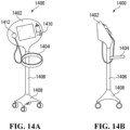
- the device is provided in the form of a cart mounted ultrasound unit, for example, a function specific transducer integrated into a cart/portable ultrasound can be provided in some embodiments.
- the device is incorporated into a hand held ultrasound device.
- the ultrasound unit is integrated into the housing.
- the processor is adapted to perform the automated detection of blood flow in the blood vessel, the processor receiving the raw data from adducing the ultrasonic waves (e.g., in a continuous beam or a pulsed beam) into the patient at an angle opposing the blood flow in the blood vessel, obtaining a velocity time trace in relation to the blood flow, determining a velocity time integral, determining a cross-sectional surface area of the blood vessel, and utilizing the velocity time integral and the cross-sectional surface area of the blood vessel to establish the blood flow through the vessel across a period of time.
- adducing the ultrasonic waves e.g., in a continuous beam or a pulsed beam
- the processor is adapted to perform a validation protocol for identifying an optimal set of parameters for operation of the device.
- the optimal set of parameters includes at least one of placement position, fixation type, selection of transducer pairs (e.g., one, some, or all) patch placement, and angle of incidence.
- the disclosure provides corresponding systems and devices, and logic structures such as machine-executable coded instruction sets for implementing such systems, devices, and methods.
- the disclosure provides corresponding systems and devices, and logic structures such as machine-executable coded instruction sets for implementing such systems, devices, and methods.
- Such devices aid in the provisioning of care of various individuals, (e.g., the critically-ill) by providing functional hemodynamic assessments (which, in some embodiments, may be instantaneous or near instantaneous).
- the device may also encounter challenges as it relates to practical implementation, for example, the device may benefit from a level of intuitiveness and/or ease of use (e.g., portability, disposability, cost, understandable process, form factor), heat management, power (e.g., battery) management, adaptability to a variety of settings (including inside and outside of a hospital), etc.
- a level of intuitiveness and/or ease of use e.g., portability, disposability, cost, understandable process, form factor
- heat management e.g., heat management
- power (e.g., battery) management adaptability to a variety of settings (including inside and outside of a hospital), etc.
- the device may benefit from a level of user-independent measurement repeatability, such that a patient, for whom many care-providers will be responsible, can monitor functional hemodynamics accurately over a protracted period of time. It may be desirable for such a device to contain access to memory and log sensor data over said protracted period of time.
- a robust measurement device may be desirable, such that the device can provide real-time feedback during, for example, chest compressions associated with cardiopulmonary resuscitation (CPR), among other operations where comparing pre-/post-intervention measurements may also be desirable. Further still, it may be desirable to provide a device that adheres to the patient such that the care-provider's hands may be freed to perform other critical functions.
- CPR cardiopulmonary resuscitation
- a device including an flexible ultrasound transducer including aligned transducer pair(s) that are used to produce an unfocused sheet of ultrasound that can sample heterogeneous tissue (e.g., muscle, vessels, blood) to quantify forward and reverse blood flow.
- the device is non-invasive and is able to perform biological measurements without the need for insertion of other components (e.g., catheters).
- the non-invasive aspect is important in some embodiments as non-invasive approaches have a substantially lower risk of infection, do not require recovery time, and are more readily adapted for use by less skilled caregivers.
- the transducer can be incorporated into a system for automatic flow monitoring and functional assessment without or with minimal user input, according to various embodiments.
- An example system may be a one-time use disposable portable ultrasound system that includes a tension bandage for secure coupling, that provides a cost-effective tool for use in emergency situations.
- the ultrasound system may be battery operated and configured for wireless communications (e.g., by cellular, WiFi, Bluetooth TM ).
- the system may have audio and graphic outputs included on the bandage, and in some embodiments, further signal processing is performed on an external device, such as a laptop, tablet or smart phone. Additional analytics may be mounted, such as components configured for determining hydration level.
- the ultrasound transducer is designed for functioning without the user having to landmark and/or focus the ultrasound transducer on the vessel of interest, for example, by having wide array of continuous wave Doppler transducers as described in various embodiments.
- An unfocused curtain of ultrasonic signals generated from an array of non-coplanar elements e.g., transducers all having the same fixed angle, angle may vary slightly due to device confirming to anatomy, or a matrix of fixed angle transducers
- a plurality of transducers may be provided, and a highest signal-to-noise ratio pair may be selected.
- the device is developed to be relatively insensitive to placement on the patient (providing multiple placement and orientation options), so that it is quick and easy to deploy (e.g., many situations need extreme deploy-ability and ease of use, such as emergency and battlefield situations). Accordingly, reproducible measures (e.g., robust repeat sampling, reduced angle variability) and constant transducer angles are capable to be provided by design, rather than reliant on the user's skill level.
- Some embodiments may be designed for hands-free usage, for example, a single operator in an intensive care unit may wish to utilize his/her hands for other functions. Other intervention may be effected while the device is in use, and ease of use and flexibility in application / placement is important as emergency caregivers may need to have their hands free to be able to administer the other intervention (e.g., fluid bolus therapy).
- the device of some embodiments is configured to track measurements pre- and post-intervention to track the efficacy of such intervention, using the fluid measurements as proxy for predicted efficacy (e.g., does there appear to be clinical improvement?).
- the ultrasound transducer is distinguished from conventional imaging ultrasound in that it is adapted for practical usage in emergency situations where speed of use and placement are critical in delivering care.
- Conventional imaging ultrasound while adapted for accuracy, typically require careful placement, good coupling, and use bulky diagnostic devices (for example, use alongside invasive diagnostic equipment, ECGs). Where careful placement is required, ultrasound system adjustments are typically needed.
- the multiple ultrasonic transducers are required to have beam intersection, presumably to aid in improving accuracy through mechanical focusing of beams. Rather than focusing a plurality of beams, some embodiments are configured to capture all or substantially all signal moving towards or away from the transducers in a large swath of tissue.
- some conventional approaches include the use of adhesive members with reference indicia for correct placement relative to anatomical landmarks, or complicated mechanisms where, for example, a plurality of transducer beams are required to intersect, among others.
- Such conventional approaches are not feasible or practical in the context of emergency care. Time is of the essence, and the ability to quickly deploy and obtain readings allows a primary caregiver a better chance of success.
- a preferred embodiment is configured to enhance the reproducibility and comparability between repeat measures before and after an intervention (e.g., across multiple distinct events to extract hemodynamic parameters from the transducer pair(s)).
- the transducer sets and the saw tooth orientation are held to have a same angle of attack (e.g., beam angle) across each of the transducer sets in respect of a plane of fluid flow. This orientation allows the mechanism to emit signals that penetrate the tissue, and creates an "'unfocused ultrasound curtain" that provides for improved ease and flexibility of placement.
- a caregiver may not necessarily have enough time to accurately determine placement, and the "unfocused ultrasound curtain" aids in establishing a redundancy of placement options such that the device or system is still operable despite suboptimal placement, providing a signal that is accurate enough for emergency care.
- the system in some confirmations, is able to monitor blood flow in two directions.
- the ultrasound transducer may be incorporated into an overall system or device (e.g., a miniaturized singular device that operates as a one-piece bandage member that can be quickly applied prior to or during emergency care) that is configured to measure signals before, during, and/or potentially after an intervention, or combinations thereof. Differences in combinations of these signals can be used to identify, for example, the occurrence of events (e.g., return of spontaneous circulation), to determine characteristics of blood flow over a period of time (e.g., a velocity-time Integral), and/or to determine the efficacy of emergency intervention (e.g., an indication of feedback regarding success of CPR).
- an overall system or device e.g., a miniaturized singular device that operates as a one-piece bandage member that can be quickly applied prior to or during emergency care
- Differences in combinations of these signals can be used to identify, for example, the occurrence of events (e.g., return of spontaneous circulation), to determine characteristics of blood flow over a period of time (e.g.,
- the device may be a standalone unit (e.g., having on-board displays or other interface elements) whereby auditory or visual displays are used to convey information regarding treatment.
- the device is operable for use with downstream processors which receive raw or processed data sets from the device, and generate one or more healthcare insights based on the processing of the data sets, and such processors may be on-board, or on a separate device or in a distributed resources implementation (e.g., a cloud-based implementation), Some embodiments may off-load processing to a connected smartphone / tablet / computer.
- on-board processors may be utilized to perform further analysis and signal processing, for example, noise removal, artifact identification, signal shaping, metric extraction, among others.
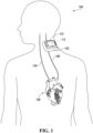
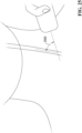
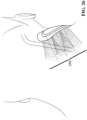
- FIG. 1 illustrates the device 102 placed on the neck of a patient, according to some embodiments.
- the device 102 is illustrated having various components and structural aspects, and it should be noted that the device 102 is provided merely as an example and embodiments may have different, alternate, the same, more, and/or less components and structural aspects.
- the patients that may use this device 102 may, for example, be older in age and suffering from heart complications.
- the patients may be weak, may not be in a state of full awareness, and may be in danger of acute and critical illness.
- the device 102 may also be suitable for various other patient types.
- a device 102 that seems to constrict or feel unnatural on the patient might serve to increase patient stress.
- a smaller device 102, or one with a detached probe, may be advantageous in this regard.
- a device 102 that is non-invasive is particularly desirable from a healthcare risk perspective.
- the device 102 shown is configured for providing automated fluid response ultrasound (AFRU), and may, for example, be a body mounted device 102 that may be configured to incorporate a portable ultrasound unit to provide one or more assessments of a patient with consistency and/or accuracy.
- the device 102 may provide functional hemodynamic assessments, for example the device 102 may determine a patient's fluid responsiveness (FR), in an automated fashion.
- the local site on the patient is generally the neck area, such that the carotid artery is the vessel of interest and carotid flow is the target measurement.
- the vessel of interest may be another vessel (e.g., brachial artery, femoral artery, etc.) and, as a result, the target measurement may change accordingly.
- the device 102 may, for example, be used in the context of various uses, including an automated ultrasound in combination with a leg raise, the use of an automated ultrasound to give live readings during a fluid challenge (e.g., passive leg raise), etc.
- the solution of the present disclosure may be non-intrusive, may be used by untrained users, may include methods by which certain target blood vessels are automatically differentiated from the other blood vessels, etc., and the device 102 may, in some embodiments, be used for multiple measurements where the device 102 may be fixed in place between measurements.
- forward and reverse flow signals may be classified as venous or arterial by application of a flow profile (e.g., pulsatile positive direction against non-pulsatile + opposite of positive direction).
- the transducer beam may be wide enough to capture the entirety of both arterial and venous signals at a particular monitored cross-section.
- a user interface 110 may be integrated or operatively paired with the device and thus the device 102 may not require external supporting hardware.
- the device may, in some embodiments, be integrated with a data communication device 112, for example using the Bluetooth TM or Wi-Fi protocol.
- the data communication device 112 may be configured such that the device is capable of transmitting outputs to an external system (e.g., an external computer system) for processing, data storage, display, etc.
- the user interface 110 may be a visual display, a speaker, or another interface capable of communicating messages to a user of the device.
- the device 102 may contain one or more data transfer buses operable to provide non-networked data connection means that may allow the device 102 to transfer and receive data to and/or from external connected devices (e.g., universal serial bus (USB) hard drives, monitors, etc.).
- external connected devices e.g., universal serial bus (USB) hard drives, monitors, etc.
- various disposables may be used with the device 102, such as a disposable which integrates a patient interface with an acoustic carrier (e.g., the gel and adhesive).
- the device may communicate data to a secondary processing system via a communications network - the secondary processing system may process received data according to data-analytics models and/or may integrate received data with previously stored data.
- the device 102 is depicted along with a patient's blood vessels (noted as reference numerals 104 and 106, in this example, the carotid).
- the output of the device 102 may be indicative of reflected hypersonic waves transmitted by transponders forming part of the device 102, and reflecting off of a vessel of interest (in this example, the carotid artery).
- the received reflected signals when processed, may produce an output indicative of hemodynamic properties of blood flow from the patient's heart 108, through the vessel of interest.
- the device 102 may output through the user interface 110, for example, as various readings that can be interpreted by a machine and/or a healthcare practitioner.
- the blood flow and/or vessel walls may be tracked using an ultrasound sensor, and denoted as reflected signals undergoing a Doppler shift.
- the measured Doppler shift may be indicative of the movement of red blood vessels in blood through an artery or vein relative to the device 102 over time.
- the reflected signals may, when measured, produce values distinct from all other vasculature, which may facilitate isolation of reflected signals from a vessel of interest.
- the measured Doppler shift over a span of time may form the velocity time integral, and may be indicative of the amount of blood passing through a cross section over the span of time.
- the device 102 may be configured to perform automated functional hemodynamic assessments in a vessel (e.g., a carotid artery, brachial artery, femoral artery, etc.). For example, the device 102 may be utilized to perform auto- focusing of an ultrasonic source (e.g., an ultrasound probe) at a number of different depths and angles, and then collect data that best fits the structure of a targeted blood vessel.
- a vessel e.g., a carotid artery, brachial artery, femoral artery, etc.
- an ultrasonic source e.g., an ultrasound probe
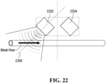
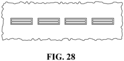
- the device 102 may include a chain of transducer pairs oriented in a saw tooth pattern such that, in concert, the transducer pairs produce ultrasonic waves at an angle of incidence between about 25 degrees to about 60 degrees in respect of a plane of fluid flow (e.g., the direction of blood flow through a blood vessel) through the at least one targeted blood vessel.
- a plane of fluid flow e.g., the direction of blood flow through a blood vessel
- the saw tooth pattern arrangement may function to aim the ultrasonic beam so as to reliably generate an angle of incidence of about 25-60 degrees (or thereabout) with general anatomical angle (for normal body types of 45 degrees). Use of this angle may enable reliable detection of reflected ultrasonic signals from the body part of the individual containing the vessel of interest toward which the ultrasonic beam (e.g., a continuous beam or pulsed beam) is directed without the intervention of a specifically trained technician or other individual.
- Acceptable angles include +/- 1 degrees, +/- 2 degrees, +/- 3 degrees, +/- 4 degrees, among others.
- the saw tooth pattern arrangement may function to make available a plurality of redundant, but effective, placement options on the body part of the individual, thus making it less difficult to obtain an effective reading from the vessel of interest.
- the saw tooth pattern of the array may be oriented such that co-planar elements all have the same or about the same angle (e.g., relative to the skin) such that an unfocused curtain of ultrasound is emitted, the unfocused nature of the ultrasound allowing for a series of redundant positioning points for positioning the device 102.
- the redundant positioning may allow for the device 102 to be used by a less skilled or, in some embodiments, even an unskilled user. Further, redundant positioning is helpful in emergency situations where non-ideal conditions in conjunction with a need for speed (e.g., individual is otherwise in great pain or dying), even for the skilled practitioner.
- multiple transducer element pair designs may also enable multi- or single element activation depending, for example, on the quality of the reflected signal received from the vessel of interest. For example, where a multi transducer element array containing 10 elements receives a reflected signal from a vessel of interest that is sufficient to allow effective functional hemodynamic monitoring, the remaining eight elements may be de-activated or may enter a low power mode. This may provide benefits to power consumption and efficiency of operation (e.g., computational efficiency) and vessel identification.
- the device 102 may be functional to perform automated functional hemodynamic assessments of a number of types of blood vessels. Depending on a particular vessel operable with the device 102 at a certain time, different depths and angles may be selected. The selection, for example, may be automated, based on the application of various pre-programmed instruction sets. The selection of such parameters is a non-trivial technical problem in view of variations of human physiology, blood vessel types, and practitioner skill levels. Further, the device 102 may operate, in some embodiments, such that it may be operable by unskilled practitioners and/or practitioners having less training (who may need to rely on the device 102 to select parameters based on sensed data and/or input data). The data retrieved from the ultrasound unit may be utilized, for example, to calculate relative blood flow (e.g., amount of blood I heart beat or unit time), and a potential advantage may enable variance in how the probe is oriented to the particular vessel being examined.
- relative blood flow e.g., amount of blood I heart beat or unit time
- the device 102 may be configured to detect relative blood flow (in one or more directions, such as forward or backward flow) through a particular vessel (e.g., the carotid artery, brachial artery, femoral artery, jugular, etc.).
- the device 102 may further be configured to indicate the level of cerebral perfusion that has occurred.
- the device 102 may further be configured to indicate whether the return of spontaneous circulation ("ROSC") has occurred.
- ROSC return of spontaneous circulation
- the device may be adapted to measure functional hemodynamic parameters (e.g., fluid dynamics) in a "binary" mode (i.e., fluid is either flowing through a vessel, or it is not).
- the device may be adapted to provide a relative measure of a hemodynamic parameter such as the amount of fluid flowing through a cross-section of the vessel over a particular period of time (e.g., carotid, femoral, brachial, etc. blood flow rate). Measurement of relative carotid flow rate may be the most effective way to automatically detect ROSC.
- some embodiments of the device are configured to apply signal processing to identify indicative waveforms (e.g., "shark-fin shaped" pulses, or other types of pulsatile-type waveforms or cardiac waveforms) which may be out of synchronicity or occur out of phase in relation to chest compressions.
- the identification of one or more "shark-fin shaped" waveforms may, for example, be indicative of a ROSC event.
- a "shark-fin" shape for example, may include pulses having one or more rounded curved sections, for example, on a leading and on a trailed edge of a pulse. In Applicant's experiments, the "shark-fin" shape was found to be particularly representative of ROSC events.
- Other shapes are also possible (e.g., pulsatile-type waveforms or cardiac waveforms), and they are indicative of ROSC events when determined to be out of synchronicity or occur out of phase in relation to chest compressions.
- the device 102 can be configured to alert the rescuer to immediately stop compressions (potentially limiting damage in emergency situations).
- ultrasound unit e.g., an ultrasound probe
- adhesives, tensioning bands, collars, pillows, etc. may be utilized.
- housing is provided to which vascular probes could be attached and fixed to the neck at varying angles.
- the device 102 may be configured to communicate through one or more communication links (e.g., wired, wireless, cellular, local area networks, wide area networks, infrared, Bluetooth TM ) with one or more receiver computing devices (e.g., for further analysis) and/or downstream computing devices (e.g., a data centre associated with a healthcare facility). Accordingly, the device 102 may or may not have a display 110.
- one or more communication links e.g., wired, wireless, cellular, local area networks, wide area networks, infrared, Bluetooth TM
- receiver computing devices e.g., for further analysis
- downstream computing devices e.g., a data centre associated with a healthcare facility.
- the device 102 may or may not have a display 110.
- the device 102 may be configured to provide outputs that may inform the function of other devices.
- the output of the measure can inform various individuals and/or machines of various hemodynamic parameters (e.g., features of the flow of blood through a vessel).
- machines delivering cardio pulmonary respiration (CPR) can provide feedback on the efficacy and timing of chest compressions.
- CPR cardio pulmonary respiration
- the device 102 may be configured to benchmark the velocity of early chest compressions (when the rescuer is fresh) based on first 3-10 chest compressions, then interpret the velocity of the blood on each compression with and providing an output (e.g., an alert, a signal, a visual indication) that informs the rescuer on how close to achieving the same efficacy in each subsequent chest compression.
- the feedback to the rescuer is particularly useful where the rescuer is not particularly experienced or skilled, and the feedback may be modified to indicate, for example, relative instruction sounds (e.g., a voice indicating "last compression was less effective than prior compressions), or other types of visual indications.
- the device 102 may have various components to detect (e.g., monitor, track, probe, sense, determine, identify, investigate) various physical characteristics of the patient.
- the device 102 of FIG. 1 may be used in conjunction with specific workflows that may be adapted such that the device 102 and the workflows intemperate to provide accurate and repeatable localization (e.g., using the ultrasound readings).
- the portable non-invasive hemodynamic monitoring device of claim 1 comprises an ultrasound unit adapted for transmitting ultrasonic waves in a continuous wave transmission and a processor configured to continuously extract hemodynamic parameters from one or more characteristics of detected reflected ultrasonic waves in real-time or near real-time by applying a signal processing routine, including processing the reflected ultrasonic waves according to a continuous wave Doppler ultrasound process.
- the portable ultrasound unit may be a continuous wave Doppler ultrasound module that is capable of emitting ultrasonic waves in a continuous beam, and that is accurate and fast enough to provide a real or near-real-time analysis of parameters of the fluid flow in the blood vessel, in some embodiments, free of a bulky cart or cord.
- the device 102 may, for example, be portable enough to be carried around by a physician (e.g., for extended periods of time) or stored for sharing by multiple practitioners (e.g., in a 'grab- and-go' charging station for physicians).
- a pulsed wave Doppler ultrasound may be provided instead.
- Continuous wave Doppler ultrasound modules may function to measure fluid velocities along the entirety of a scanned channel.
- a continuous wave Doppler method may measure the velocities of fluids traveling through the entire scanned portion of the blood vessel over a period of time.
- pulsed wave Doppler ultrasound modules may only allow measurement of fluid velocities at a single point, or a very finite sequence of points, along a scanned channel.
- Pulsed wave Doppler ultrasound modules may function by emitting a pulsed signal toward an area of focus for a finite period of time, then ceasing the emission of said signal and monitoring received signals in order to record a reflected frequency shift related to the original emitted signal for a finite period of time. This process is then repeated. Once the reflected signal is received, a processor calculates the velocity and flow of liquid through a channel at the area of focus (e.g., a blood vessel).
- a channel at the area of focus e.g., a blood vessel
- pulsed wave Doppler ultrasound techniques require a finite signal emission period and a second finite signal monitoring period, there is a limit to how fast said techniques can accurately measure the flow of liquid through a channel - where the velocity of the fluid surpasses a certain point, temporal aliasing (a phenomenon whereby a recorded signal appears distorted due to a recording system with an insufficient sampling rate).
- This mode of operation can be described as "half-duplex".
- Continuous wave Doppler ultrasound modules function by emitting ultrasound signals in a continuous beam along a channel and continuously monitoring the multitude of reflected frequency shifts via a detector.
- This mode of operation can be described as "full-duplex" as the continuous wave Doppler ultrasound is continuously emitting and receiving signals.
- a potential advantage realized by this mode is that it enables the measurement of high-velocity flows of liquids through channels (e.g., blood through blood vessels) that could not be accurately measured using pulse wave Doppler ultrasound techniques due to the above-described temporal aliasing problem.
- the device 102 may further include and/or be associated with a locating disposable that may be affixed once to the patient for various measurements, the measurements of which can be compared with one another.
- the device 102 and/or the locating disposable may require a level of ease of use and sufficient accuracy such that practitioners and care centres may readily adopt its usage.
- the device 102 may be battery powered and may use a transducer array which may function to measure the Doppler shift produced by fluid passing through a vessel (e.g., a Doppler shift produced by red blood cells in blood travelling through an artery relative to the position of the device 102.
- a vessel e.g., a Doppler shift produced by red blood cells in blood travelling through an artery relative to the position of the device 102.
- a technical challenge arises in relation to ensuring that the device 102 is configurable to identify (e.g., delineate, distinguish) flow through particular vessels (e.g., distinguish carotid flow from the jugular vein or other confounding objects).
- a patch-like (or collar-style) probe may be adhered to local area of skin on a patient under which the patient's carotid artery (or other vasculature) passes.
- the probe may utilize ultrasound signal processing methods (e.g., Doppler signal processing functions) to identify pulsatile flow.
- Doppler signal processing functions e.g., Doppler signal processing functions
- a velocity-time trace may be obtained.
- a unit time may be defined.
- the device 102 and/or a downstream device may utilize the data to determine the velocity-time integral ("VTI"), and the VTI may be multiplied by the cross-sectional surface area of the vessel over the time of one cardiac cycle (heart beat).
- VTI velocity-time integral
- the velocity time integral is proportional to the volume of blood that flows through a vessel per unit time. Therefore, it is a surrogate for cardiac output which is an important hemodynamic perimeter (e.g., a proxy that can be obtained based on measured physiological indicators).
- the VTI can be used, for example, to track an average of VTI over a period of time prior to performing an intervention (30s window), perform an intervention (30s window), and to calculate average VTI over a period of time after performing an intervention (30s window).
- the VTI is used as a proxy to determine the efficacy of the intervention, which is useful feedback in emergency situations.
- a portable blood flow monitoring device 102 on detecting effective treatment, may indicate via tactile (e.g., vibration motor), auditory (e.g., speaker) or visual (e.g., GUI) mechanisms that CPR should stop, potentially preventing additional trauma to the patient that otherwise would have occurred if CPR continued (e.g., broken ribs, sternum fractures, internal organ damage).
- an automated physical measurement of a blood flow through the vessel per heartbeat may be obtained using an ultrasonic approach.
- an auto focusing mechanism is provided, where the device 102 may conduct a validation protocol to identify which settings are optimal (e.g., frequency, angle) for the patient's body, patch placement, and/or other parameters.
- a validation protocol e.g., frequency, angle
- a challenge with conventional technologies is that the selection of these signals is non-trivial and may often lead to a high level of training required. For example, this aspect of the technology aids in allowing un-trained or less trained personnel to use the device 102 reliably.
- a computing device may apply an algorithm in conjunction with detected readings to determine the patient's velocity time integral (VTI, pre-challenge); prompt the physician for a fluid challenge (e.g., passive leg raise); detect and/or calculate a post-challenge VTI; and deliver an assessment of the patient's fluid responsiveness (increase of >10% VTI or output following fluid challenge).
- VTI velocity time integral
- a ratio may be found between pre and post-challenge VTls, and other thresholds may be used for assessments (e.g., 10%, 5%, 3%, etc. and may be indicative of an increase or decrease).
- a condition is broken (e.g., as provided through a business rule), or a trigger triggered, a notification may be generated and/or provided (e.g., an alert, a sound, a display, a pop-up).
- a display may, for example, aid the physician by providing various types of views, some views having various transformations (e.g., a simplified view), annotations (e.g., display markers, dynamic markers), analytics (e.g., determined aspects, averages, means, medians, identified aberrations), and/or a raw data view. For example, a post-/pre-VTI ratio may be determined, and a 10% or greater ratio may be indicative of a fluid responsiveness condition. Accordingly, some embodiments may be utilized to detect and/or determine various characteristics in relation to a carotid anomaly, or detect a carotid anomaly or an anomaly regarding another vessel of interest (e.g., brachial artery, femoral artery, etc.).
- another vessel of interest e.g., brachial artery, femoral artery, etc.
- the device 102 of some embodiments may be configured such that there may only be a minimum level of required hardware to effectively monitor blood flow, and may reflect a trade of multi-functionality for size, providing additional benefits as in relation to operation for use with carotid flow procedures.
- a conventional ultrasound unit, the GE VScan TM 202 is pictured, having a display 204, and a probe 206.
- Pulmonary artery catheterization is another technique that may be available for hemodynamic monitoring, wherein a catheter is inserted into the pulmonary artery via the vena cava to directly measure cardiac output. Pulmonary artery catheterization can measure right atrium, right ventricle, and pulmonary artery pressure, as well as left atrium input pressure, but a major drawback is that the catheterization is invasive and limited to surgical use.
- Pulse Pressure Waveform Analysis is another technique that utilizes the arterial waveform, obtained either from an arterial catheter or a finger probe, in order to calculate the stroke volume (SV) and the systemic vascular resistance (SVR), but complications may arise in view of non-linear and varying arterial wall compliance.
- Phase shift technology I bio reactance approaches may be considered for use, wherein when an AC current is applied to the thorax, the pulsatile blood flow taking place in the large thoracic arteries causes the amplitude of the applied thoracic voltage to change.
- Research has indicated poor performance in relation to critically-ill/post-operative patients; further, this approach may be hindered by environmental factors, such as overweight or patients which perspire heavily.
- Gas rebreathing techniques may also be used in relation to estimating CO non-invasively, but while easy to use, they have been shown to be adverse affected by spontaneously breathing patients.
- Septic Shock Algorithms may use aggregated historical data to predict the onset of septic shock, which can be diagnosed through blood pressure readings.
- the device may produce outputs functioning to allow detection of various types of compensated shock.
- Compensated shock may be defined, in an adult example, as systolic blood pressure above 90 mm Hg while exhibiting signs of inadequate perfusion (e.g., tachycardia).
- the device may transmit an alert signal via a sensory output device.
- compensated shock can be determined as a ratio between HR/systolic blood pressure.
- this is not a very sensitive method as blood pressure takes a long time to change during shock.
- An improved method of some embodiments determines / generates a prediction of compensated shock by generating a comparison between heart rate and the measured velocity time integral (e.g., a HR/VTI ratio).
- the improved method generates a more sensitive marker as VTI corresponds more directly to the state of the heart. Accordingly, the improved approach enables earlier detection of patients in compensated shock.
- the device is configured to determine / flag changes in in the HR/VTI ratio, and as the ratio becomes larger, the patient is flagged as potentially entering into shock (and corresponding workflows may be invoked, for example, to generate one or more alarm notifications).
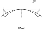
- FIG. 3 is an illustration of an example neck profile, according to some embodiments.
- Patients may have differing anthropometric parameters, including, for example, carotid anthropometries, neck anthropometries, etc. These parameters may be taken into consideration, for example, as the device may need to be fitted on to and/or used in close proximity to bodily features of the patients, and thus may need to be calibrated and/or accurately positioned.
- anthropometric parameters including, for example, carotid anthropometries, neck anthropometries, etc.
- the minimum size (i.e. length) of the neck may determine the maximum size of a body mounted device.
- the neck length for the smallest 5% of the population is roughly 8 cm, and accordingly, the maximum comfortable height of the device may approximately be 8 cm.
- Neck circumference also varies from person to person.
- the smallest neck circumferences may be about 312 mm, and the largest about 463 mm.
- the patient's neck would have to conform roughly 14 mm at the edges, too much for patient comfort. If the device were curved, the neck would have to only conform roughly 5 mm, but a curved feature may add complexity (and likely size) to the device and/or components thereof.
- the neck anatomy may be fairly consistent from patient to patient.
- the internal diameter of the Common Carotid Artery may be approximately 6.2 mm for women and 6.5 mm for men, ranging between 4.3 and 7.7 mm in maximum and minimum sizes (as noted in a study having a study size of 123).
- the standard depth for a patient's CCA may be 20-40 mm below the skin.
- the wall thickness may be roughly 0.75 mm.
- the diameter of the CCA may expand roughly 0.5 mm with every heartbeat.
- the ratio of the internal carotid and external carotid artery diameters can be predicted as approximately .65 and .58 respectively (e.g., each is roughly 1/2 to 2/3 of the diameter of the CCA).
- the vertebral artery may be hidden in bone, very far away and very small.
- the jugular vein has blood flowing in the opposite direction (therefore "up" may have to be established).
- Directional information can aid in the assessment of position. Dimensional measurements can also be used to aid in position by assuming any measurement of a 5 diameter less than 4.3 mm is likely not the CCA.
- a CCA further from the skin implies a larger bodied patient, who would be expected to have a larger CCA.
- transducer pairs may be arranged end to end to form the transducer array. This may enable the device to contour to different patient morphologies on the neck, arm, torso and/or thigh, etc.
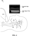
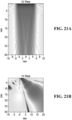
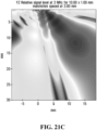
- FIG. 4 is a depiction of a CCA flow measurement angle, according to some embodiments.
- a probe 402 is shown for measuring flow in relation to vessels 404, being incident flow at plane 406. Accordingly, sample images 408 (greyscale) and 410 (color) are shown.
- the ultrasound unit may include a transverse and oblique array.
- the transverse oblique array may be preferable in some embodiments.
- the array may be oriented obliquely (as shown by the line indicative of plane 406) to pass through the CCA such that the array can read anatomical information in the transverse plane, and Doppler signal processing information in the longitudinal plane.
- the ultrasound architecture may be an important aspect of the device, an ultrasound investigation was conducted to test the effectiveness of the transverse array configuration.
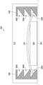
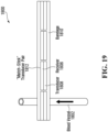
- FIG. 5 is an illustration of an example tensioning mechanism for maintaining acoustic coupling between a device 504 and a body part 502 according to some embodiments.
- the device 504 housed in a housing 512 which may adhere to the surface of a body part 502 containing a vessel of interest.
- the housing may further contain a tensioning cover 510 which may be coupled on one side to the device 504.
- the housing may further contain two or more latching mechanisms 506 which may be situated perpendicularly to the body part 502 of the individual and within the housing 512.
- the latching mechanisms may each contain a plurality of latching channels 506a-f which may function to receive the edges of the tensioning cover 510 when downward force is applied thereto and hold the tensioning cover 510 in place, thereby causing the tensioning cover 510 to maintain position and, by extension, apply downward force to the device 504 such that it remains secure against the body part of the individual 502. This may cause the device 504 to be situated such that it maintains a position functional to produce a correct signal and read a correct reflected signal to and from the vessel of interest (e.g., within a correct range of distances from the vessel of interest).
- FIG. 6 is an example block schematic diagram of a device, according to some embodiments.
- FIG. 6 illustrates an electrical architecture and may include various elements of electronic circuitry, etc.
- the device may be implemented in various forms, including, for example, by software, hardware, embedded firmware, and/or a combination thereof.
- a user interface 602 may be provided for various input I sensory-output functionality, including the ability to receive parameters, etc. from users (e.g., patients, clinicians). Output functionality may be used to, for example, provide a graphical interface for clinicians and/or to communicate information to downstream computing systems (e.g., a clinical data center).
- users e.g., patients, clinicians
- Output functionality may be used to, for example, provide a graphical interface for clinicians and/or to communicate information to downstream computing systems (e.g., a clinical data center).
- the device may also, in some embodiments, have on-board memory that may be used to support various functionality, such as processing data for display to a clinician, etc.
- Various peripherals 606 may be utilized to provide various input signals and/or to receive various outputs (e.g., through USB, Bluetooth, etc.).
- the processor 604, for example, may be configured to control the peripherals 606, and the user interface 602.
- Ultrasound components may be provided, for example, through an ultrasound front end 612, a probe, transducers 616a ... 616n, which may be placed on and/or in proximity to a patient 618.
- a power supply 610 (e.g., a battery), may be utilized to supply power to the ultrasound components.
- the user interface 602 may be provided on a separate computing device, communicating with the Central Processing Unit (“CPU”) 604 via one or more Peripherals 605, hence the user interface 602 is depicted as connecting to the CPU 604 via a dashed line.
- CPU Central Processing Unit
- the front end may be provided and, in some embodiments, may include an eight-channel integrated circuit that may include the ultrasound front-end 612, the probe 614, and the transducers 616a ... 616n. Signals passing through the front-end first may be amplified and/or filtered, and then passed through an anti-aliasing filter which may remove frequencies that may be too high to be sampled. These signals may then pass through an analog-to-digital converter and may be provided to a configurable integrated circuit (e.g., a field programmable gate array (FPGA), or a custom integrated circuit) 608 as, in some embodiments, low-voltage differential signals (LVDS).
- FPGA field programmable gate array
- LVDS low-voltage differential signals
- An ultrasound emitter may be utilized to produce the high-voltage signal needed to drive the ultrasound transducers.
- the emitter may be provided a +60V and a - 60V power supply, and controlled by low-voltage logic signals from the configurable integrated circuit.
- Other voltages and/or power supplies may be utilized and the above is provided as an example.
- the configurable integrated circuit 608 may be configured to control the emitter and receive LVDS signals from the front-end.
- the configurable integrated circuit 608 may be configured to perform digital signal processing that may be utilized to both send and receive signals, including beam-forming and Doppler shift computations.
- the CPU 604 may host the operating system of the device, and may liaise between the configurable integrated circuit 608, user interface (Ul) 602 and any peripherals 606 that may be added to the system and/or perform post-processing on signals received from the configurable integrated circuit 608.
- the UI 602 may include an LCD touchscreen and/or an LCD screen with buttons. Other types of displays may be contemplated. Indicator lights, comprising for example LEDs, and indicators sounds generated from a speaker may also be part of the user interface 602 to provide feedback to the operator. In some embodiments, feedback corresponds to operating conditions of device 102 in order to direct the operator to orient device 102 to a desirable and/or acceptable local site on the patient. The purpose of this direction may be to permit full operability of the device with a minimum of training or experience. If the device is required to be connected to the cloud, an onboard Wi-Fi module can be included along with additional peripherals 606 such as Bluetooth or USB.
- additional peripherals 606 such as Bluetooth or USB.
- a printed circuit board may be provided to host some or all of the electronic components within a structure (e.g., a housing, a base).
- the device may be powered by a rechargeable or replaceable battery, which may be used to drive both the ultrasound and/or the other electronics (e.g., LCD screens, etc.).
- lithium-ion technology may, in some embodiments, be selected as an option for compact power density. Operating under the assumption that these batteries typically can store 77,000 Ah/cm 3 (amp-hours per cubic centimetre), the battery in the device may have to be, for example, 125 cm 3 for 1 hour of continuous active use. A Li-ion battery of this size may typically weighs about 250 g. Additional lifetime can be achieved by adding a larger (and heavier) battery, which may be suitable for a larger embodiment.
- FIG. 7 is illustrative of some example components that may be utilized for interfacing with a patient's body, according to some embodiments.
- the method with which the device interfaces with the body may be an important factor for consideration.
- a component for example, may be a "disposable" to connect (acoustically) the probe to the skin, and connect (mechanically) the device to the patient.
- Sample disposables are indicated at 702 and 704.
- the disposable may integrate these aspects for quick application and disposition. This may avoid the disadvantage of applying ultrasound gel separately, which creates variability and mess.
- an approach includes combining the requirements into one solution: applying an acoustically transmissive adhesive (i.e., the adhesive also serves as the gel).
- the requirements may be separated: a material is provided for acoustic coupling and a material is provided for physical connection.
- An example design may include utilizing an adhesive ring with a gel pad center.
- the adhesive connects the device and the gel (solid or liquid) provides an acoustic connection. The user would simply peel back the inside of the disposable stick it to the device, and then remove the cover of the patient side immediately before application.
- the disposables may not need to be sterile (unless applications to open wounds are included in the indications), but should be held to a level of cleanliness typical of the industry.
- Disposable ultrasound pads such as Rich-Mar AutoGel TM , BlueMTech TM and Aquaflex TM ultrasound gel pads, may be provided to replace ultrasound gel (for the purposes of limiting cleanup) and may be utilized with the device. These pads may need to be wetted with water, and a standoff pad may be used to position the probe away to get a clearer picture of superficial areas of the skin (for example, ATS TM phantoms).
- a custom sized block can be centered under the probe head, adhered on one side to the device and covered on the other side by a dust cover that also keeps the disposable wetted.
- ultrasound gel may be utilized.
- Gel could be pre-applied in a cavity in the disposable.
- a similar peel-back cover could expose the gel and make it ready for application. After use, the gel may have to be wiped off the patient.
- An alternative method of acoustic coupling is a liquid filled pad. Similar to an ultrasound pad in its function and composition, these bags are filled entirely with liquid. A thinner liquid eliminates the likelihood of bubbles in the medium, but adds issues at the wall interface and with filling. For these reasons, liquid pads may be a less desirable alternative to those listed above.
- a tensioning material e.g., a tension bandage
- a tensioning material may be positioned around the body in order to provide a force normal to device 102 and ensure sufficient acoustic coupling.
- FIG. 8 depicts an example adhesive by 3M TM .
- Adhesives may by hypo-allergenic and may stay in place for a number of days.
- the adhesive 802 may help keep a device and/or a portion thereof positioned in the target local site on the patient.
- Silicone may be used as a protector and an acoustic coupling material for the probe/human interface, often used in conjunction with gel.
- the need for gel may be reduced and silicone alone might be effective.
- a drawback to silicone is a reduced speed of sound, which may require an algorithm to correct.
- the device may require a mechanical housing that may vary in detail between embodiments.
- a rigid two part housing for example, may be sufficient to provide a structure, with standoff points to hold the electronics.
- the housing may include spacers between components to avoid rattle or internal movement.
- the housing may need to be cleanable, and so may include gaskets to prevent water ingress at the seam, display, and buttons (keypad membrane).
- Heat management may be an important consideration.
- the device may consume significant amounts of energy during use, and accordingly, the hot features of the device may need to be kept away from the patient to reduce the risk of burning (e.g., must be less than 43°C per ISO 60601).
- a plastic housing may be a natural insulator but may cause the electronics to overheat.
- a metal housing may have advantageous attributes: protecting the electronics at the expense of patient safety. If an embodiment is applied that does not connect to the patient directly then heat protection may not be a requirement.
- the housing is plastic, injection moulding can be used for manufacturing. If a metal housing is used, numerous options are available, though some may be more costly than injection moulding.
- the device may be provided as a single part. In some embodiments, the device is provided in having two or more parts; these parts may comprise a body, a probe, a separate computing device, a stand-alone cart, among others. For these embodiments, a probe wire may be provided to connect the body of the device to the probe.
- Wires for this application may be available and may need to be strong enough to avoid pullout if the patient moves or the device falls.
- the probe itself (or the connecting surface on a one-part device) may benefit from a silicone interface piece, to protect the device and allow some conformity.
- FIGS. 9A-9C , 10 , 11A-11C , 12A , 128 , 13A-13C , 14A -148, 16 , 17 may be illustrative of some sample embodiments of the device.
- FIGS. 9A-9C illustrate a pocket-sized embodiment
- FIG. 9A provides a top elevation view
- FIG. 9B provides a perspective view
- FIG. 9C provides a side cross-sectional view, according to some embodiments.
- an embodiment may include a pocket sized, body mounted ultrasound device that can be carried around by a clinician (e.g., the attending physician).
- the device may have an adhesive ring 902, a body section 904, and/or a display 906.
- the adhesive ring 902 may provide an adhesive force between the periphery of the body section 904 and the local site on the patient's skin.
- a concave space 908 may be provided for a gel pad or liquid gel.
- the size of this embodiment may be reduced by using a number of strategies, including, for example: offloading processing and display to another device such as a tablet (or smartphone), changing its geometry to rest partially elsewhere, measuring flow in a different artery (to reduce comparative size), or reducing the battery life or removing it entirely (plug-in power only).
- a number of strategies including, for example: offloading processing and display to another device such as a tablet (or smartphone), changing its geometry to rest partially elsewhere, measuring flow in a different artery (to reduce comparative size), or reducing the battery life or removing it entirely (plug-in power only).
- FIG. 10 is an illustration of a pocket-sized embodiment.
- the embodiment may have display 1004, a power button 1002, and other buttons 1006 and 1008 that may be used, for example, to perform various input and output functions.
- FIGS. 11A-11C may be illustrative of a small embodiment with a coupled probe, according to some embodiments.
- FIG. 11A is a front perspective view of the embodiment
- FIG. 11B is a rear perspective view of the embodiment
- FIG. 11C is a partial view of the embodiment.
- the device may, for example, have a display 1102, control button 1104, power button 1106, an integrated handle 1108, a cable management apparatus 1110, a probe 1112, a charging port interface 1114, a printed circuit board stack 1116, and a battery 1118.
- a coupled probe may provide a lower risk alternative to the pocket sized unit, while still being small and portable.
- the adhesive probe-patch may be coupled to the base unit via a cable.
- the clinician may place the unit on the examination table anywhere within range of the patient's neck, and extend and connect the probe.
- the probe may stay in place during the examination and possibly longer (for repeated exams).
- the device may be powered by a larger, more powerful battery than possible in a pocket-sized unit, but is also can support a wall plug for heavy use.
- the device may (in some embodiments) be too large to be carried around constantly, the device may be left at the charging station between patients, further extending battery life.
- the device may also be large enough to carry a gel holder, or an area to keep extra disposables.
- the device may include Wi-Fi and/or Bluetooth connectivity, or can transfer data via a base station. In other embodiments, the device may be miniaturized for portable use.
- FIGS. 12A-12B and FIGS. 13A-13C may be illustrative of a small embodiment with integrated probe, according to some embodiments.
- FIG. 12A is a side view of this embodiment
- FIG. 12B is a perspective view of this embodiment.
- FIG. 13A is a perspective view of a second version of the embodiment with integrated probe being held at a handle
- FIG. 13B is a perspective view of the second version;
- FIG. 13C is a side view.
- the embodiment may include a probe 1204 for use with a patient 1202/1310, a base 1206, a display 1208/1306, and an adjustable neck 1210/1305.
- a handle 1312 is provided.
- the device does not have a separated probe. Instead, and area of the main chassis contains the ultrasound head which may be placed against the patient.
- these embodiments may contain a larger battery, a plug, wireless connectivity, and may contain storage for disposables.
- the embodiments may be simpler in design and use than the coupled probe, and more durable.
- a disposable may not be necessary, or if necessary may be a simpler disposable.
- FIGS. 14A and 12B A cart embodiment is provided at FIGS. 14A and 12B ;
- FIG. 14A is a front perspective view of a cart embodiment, and
- FIG. 14B is a side elevation view of the cart embodiment.
- the application on a medical cart may provide some advantages.
- the central architecture does not differ significantly to other carts: the device 1402 may be provided on a cart apparatus 1406, having a handle 1404, and a base 1408.
- the embodiment may include a computer, monitor and screen 1410, with an ultrasound probe 1412, which may aid in simplifying the development process though the use of commercial components. Less effort may need to be focused on miniaturization and integration than a more aggressive size.
- the cart embodiment may also avoid logistical issues that may be present with portable units: for example, the embodiment may be unlikely to be lost or dropped, it may not require an area on the patient's bed to be positioned upon, and can be easily plugged in (or battery powered) with room for a long cord.
- the device may also not require an included charging station, and may thus be marketed as an individual unit.
- the device may include a chassis 1206 and a user interface 1208 (i.e., a large touchscreen), and a probe 1204 that may differ significantly from other ultrasound units.
- a chassis 1206 and a user interface 1208 i.e., a large touchscreen
- a probe 1204 may differ significantly from other ultrasound units.
- the probe 1204 may include a small adhesive patch at the end of a connection cable 1210 which can be installed on the patient and remains stuck during the procedure (or longer).
- the software may be configured to automatically find the CCA and to obtain readings, displaying only the results to the clinician (e.g., a physician) and eliminating the need for ultrasound expertise.
- An example patient-care profile 1500 is provided in FIG. 15 .
- Assessment of functional hemodynamic parameters may be desirable at each phase of the patient-care profile 1500.
- Different care-providers may be responsible at designated phases.
- a functional hemodynamics measurement device that is unique to a patient may be desirable in order to provide continuous monitoring between phases and care-providers.
- a functional hemodynamics measurement device that is unique to a care-provider may be desirable to provide monitoring of functional hemodynamics measurement to a plurality of patients.
- an adhesive 1606/1704 may be employed to fix the device to the local site on the patient's skin; a tensioning material 1608/1708 may further be employed to apply a force normal to sensor housing 1612/1712, and towards the local site in order to fix the device relative to the local site.
- the tensioning material 1608/1708 may comprise a band, to be slug around the patient in order that tension may be adjusted by altering the length of upstretched band.
- the tensioning material may further be elastic, in order to eliminate discomfort to the patient, and also continue providing sufficient normal force while the patient moves and the body change shape.
- sensor housing 1602 may contain a transducer array 1602, electronics, including but not limited to a visual display, speakers, and/or battery 1610, and other electronics.
- sensor housing 1612 is shaped like a half of an ellipsoid or American football. These shapes were found to be particularly useful in aiding proper positioning and tension characteristics to be applied.
- the sensor housing 1612 may contain a user interface unit 1620, which may be a sensory output device operable with the visual display, speakers, and/or battery 1610.
- the user interface unit 1620 may function to communicate inputs generated by a user interaction to the device.
- the user interface unit 1620 may comprise a sensory output device such as a capacitive touch input device coupled with a visual display 1610.
- the user interface unit 1620 may function to allow the user to input selections that, when received by the device, cause the device to modify its operation mode (e.g., user input may cause the device to being a process operable to determine a pre-intervention/post-intervention VTI ratio as described below).
- the transducer array 1602 comprises transducer-receiver pairs, where the transducer component generates acoustic waves, transferred into the patient acoustically through a hydrogel or acoustic coupler 1604.
- the acoustic waves travel through the patient, and are modulated and reflected by media interfaces, for example fluid within a blood vessel. Reflected and modulated waves are sensed by a receiver component in the transducer-receiver pair and within the larger transducer array 1602.
- the Doppler shift in a frequency modulated signal generated by the transducer 1602 may provide an accurate representation of the velocity of an element.
- the element to be measured is the fluid flow within a blood vessel; non-limiting examples including the carotid artery, the brachial artery, or the femoral artery.
- a sensor consisting of a ultrasound transducer 1804 and receiver 1806 may be configured as depicted in FIG. 18 and FIG. 19 , representing a cross-sectional view and an overhead view respectively.
- Transducer 1804 and Receiver 1806 may be configured such that they parallel to each other, and each directed at a 45 degree angle to the transverse plane (i.e., the plane defined by the surface of the skin 1808 at the local site on the patient).
- the transducer 1804 and receiver 1806 may resemble two match-sticks, tangent along one edge, as depicted in FIG. 18 .
- the orientation of the transducer 1804 and receiver 1806 is configured such that the angle between the vectors defined by the direction of the ultrasound wave and the direction of blood flow is approximately 45 degrees.
- the transducer pair 1802 can detect blood flow direction by the sign (i.e., positive or negative) of the Doppler shift.
- the ability to track blood flow direction may aid significantly in diagnosing various ailments or determining whether one or more health-related events have taken place. For example, a change in blood flow direction may indicate that the patient's wound has been successfully sealed, that the patient's circulatory system is working (not working), CPR has been successful, the patient is bleeding out and requires immediate attention, among others.
- the acceptable functional range is about 45-degrees ⁇ 15-degrees, with 45-degrees representing the preferred embodiment.
- the acceptable functional range may be about 44-degrees ⁇ 14-degrees, about 46-degrees ⁇ 16-degrees, etc.
- the ultrasound wave i.e., Doppler beam
- the ultrasound wave is "unfocused"; that is, the beams sweep out an angle of approximately 20-degrees, such that by directing the beam approximately 45-degrees from the transverse plane (as defined by the plane of the skin at the local site), the transducer 1804 will generate a wave that intersects with the blood vessel, and the angle of acceptance of the receiver 1806 (also 20-degrees) is large enough to receive the reflected and modulated signal generated by the blood flow.
- the width of the transducer face may be as small as 0.34 mm. This size is suitable for high-frequency (i.e., approximately 7 MHz) applications where high focal loss may be acceptable. Further, the width of the transducer may be as large as 2.15 mm. This size is suitable for low-frequency (i.e., approximately 4 MHz) applications where only low focal loss is acceptable.
- a beam that sweeps out approximately 60-degrees can be constructed.
- the width of the transducer face may be as small as 0.924 mm. This size is suitable for low-frequency (i.e., approximately 4 MHz) applications where high focal loss may be acceptable. Further, the width of the transducer may be as large as 1.52 mm. This size is suitable for high-frequency (i.e., approximately 7 MHz) applications where only low focal loss is acceptable.
- the functional frequencies of ultrasound waves generated by the transducer 1804 and detectable by the receiver 1806 are approximately 3-8 MHz. In some embodiments, approximately 5 MHz may be the frequency generated by the transducer 1804. Typically, a lower frequency may desirable for larger patients, as vessels such as the carotid artery, femoral artery, brachial artery, etc. are typically further below the skin surface 1808.
- the orientation of the "match-stick” configured transducer pair 1802 may, in some embodiments, be fixed relative to the skin surface 1808 by a tensioned bandage 1810 which provides a force normal to the transducer pair 1812 and directed towards the skin surface 1808.
- an audio or visual cue based on the Doppler shift measured by the ultrasound transducer pair 1802 may guide the placement of the device relative to the local site on the patient.
- a stronger signal relative to the noise sensed by the transducer pair 1802 may be processed by the CPU 604 and outputted to a peripheral speaker or display 606.
- the output may comprise, for example, a particular sound (e.g. "whoosh"), a change in volume, or frequency of beeps in the case of an audio cue, or it may comprise, for example, brightness, number of LEDs activated, the flashing of a pre-selected image, among others in the case of a visual cue.
- the senor consists of a "chain" of transducer pairs 1802, as depicted in FIG. 19 .
- Transducer pairs 1802 are mutually connected via co-axial cable. The increased length to the overall sensor increases the acceptable area that the device may be placed by increasing the likelihood that the target blood vessel passes under at least one transducer pair 1802.
- a "chain" may be preferable to a singular, but longer transducer pair 1802, because it may allow the housing to be constructed out of a flexible material that in turn will better conform to the various shapes and sizes of patients.
- the transducer may be a flexible polymer transducer (e.g., a highly non-reactive thermoplastic fluoropolymer such as Polyvinylidene difluoride (PVDF)), this may also allow the housing to be constructed out of a flexible material and enable the housing to better conform to patients of various shapes and sizes. Producing the external housing in a flexible fashion may facilitate better acoustic coupling between the device 102 and the body and a higher signal to noise ratio.
- PVDF Polyvinylidene difluoride
- the transducer pair 1804 is a piezo-ceramic material.
- each piezo ceramic element, representing an individual transducer 1804 or receiver 1806 is 10x1x1 mm in shape.
- the piezo-ceramics in some embodiments may be a PZT-5A or PZT-5H or a combination thereof.
- the current draw is approximately 25 mAh.
- the device may have a mode designed to conserve power and extend battery life. For example, the device may turn on only a pre-set times or it may only turn on at the request of a user and automatically turn off (or "sleep") after a defined period of time.
- FIG. 20 illustrates an example surface profile of a matchstick element, according to some embodiments.
- the transducer pairs 1804 may be adapted to sense peak velocity of the Doppler Shift, VTI, or the pre-intervention/post-intervention VTI ratio.
- the device 108 may, according to a pre-programmed instruction set, implement one or more "sampling windows" which may perform a calibration routine functional to eliminate the inherent variability of Doppler signal.
- the calibration routine may: a) record signals recorded by the transducer pair during a pre-defined span of time prior to the intervention (e.g., 10 seconds) as a "pre-intervention window”; b) cease recording signals during a corresponding pre-defined span of time during the intervention as an "intervention window”; and c) record signals during a corresponding pre-defined span of time subsequent to the intervention as a "post-intervention window”.
- the VTI is determined, in accordance with a preferred embodiment, based on a based on a baseline sampling prior to intervention. During the time of intervention, various measurements may be taken, in some embodiments. Following intervention, a post-intervention sampling (on the same time period as baseline sample) is determined, and in the preferred embodiment, a VTI ratio is generated pre and post intervention.
- the VTI determination is a useful, non-invasive technique that, without additional
- One advantage of the device is the ability to measure both heart rate (“HR”) and VTI. This permits the calculation of the HR/VTI ratio - an index that (unlike the Shock Index) is not subject to vascular constriction as a compensatory mechanism during the onset of shock.
- the design, orientation, and frequency of the ultrasonic transducers are specifically designed to facilitate the rapid and repeatable measurement of the signal of interest (e.g., the ultrasonic signal reflected from the vessel of interest). Subsequently, the measured signal of interest is automatically processed by the signal processing routine in order to generate an output.
- the signal of interest e.g., the ultrasonic signal reflected from the vessel of interest.
- Currently available point of care ultrasound machines require several manual steps to be completed in order to return a valid output. Further, successfully completing several of these steps requires users to have specific training and skill. For example, currently available point of care ultrasound machines may require: manual identification of the vessel of interest using an ultrasound imaging screen; manual orientation of the angle of an ultrasound probe in relation to the vessel of interest to produce useful readings; manual identification of the vessel of interest to activate a Doppler function (e.g., a Doppler signal processing function); maintaining a substantially motionless positioning of both the ultrasound probe and the body part containing the vessel of interest; and manually executing a command in order to cause a reading to be taken. Further, often these steps must be executed repeatedly in order to compare changes in outputs received pre and post intervention (e.g., pre and post introduction of a medicament).
- Doppler function e.g., a Doppler signal processing function
- some embodiments described herein may: automate some or all of the previously described steps; remove or reduce the requirement for manual identification of a vessel of interest; remove or reduce the requirement to manually orientate the ultrasonic transducer(s) relative to the body part of the person containing the vessel of interest; may automate the process of identifying a vessel of interest and activating a Doppler function; may serve to automatically or substantially automatically maintain a substantially motionless positioning of the ultrasonic transducer(s) relative to the vessel of interest; and may automatically generate readings, outputs, and compare pre and post intervention values to measure changes.
- FIG. 21A and FIG. 21B are "heat map" plots of the ultrasonic signals generated by the matchstick transducers, according to some embodiments.
- FIG. 21A is illustrative of the signal generated in the XZ plane, with the darkness indicative of signal strength.
- FIG. 21B is illustrative of the signal generated in the YZ plane. As indicated in FIG. 21B , the beam is generated at about 45 degree angle in the YZ plane, and the beam is "wedge" / conical shaped.
- a conical shape for example, may include an oval cone, and in some embodiments, may be frusto-conical.
- FIG. 21C is a more detailed version of FIG. 20B, showing the beam "wedge" in greater detail.
- the relative signal strength is shown at 3 MHz for a matchstick transducer having the dimensions of 10x1 mm, spaced at 3 mm.
- FIG. 22 illustrates two matchstick elements and a blood vessel of interest, according to some embodiments.
- a first matchstick element 2202 provides a signal transmit function whereby the ultrasound signal is generated in a wedge shape towards the blood vessel 2206, for example, along center axis 2208.
- a second matchstick element 2204 is configured to receive the signal that is reflected from blood vessel 2206. The orientation is important in some embodiments, the first matchstick element 2202 is positioned in front of the second matchstick element 2204 such that the signal emanating from first matchstick element 2202 is not inadvertently impeded by the second matchstick element 2204.
- the device may need to be oriented at least roughly in the correct direction. Accordingly, there may be a rough "up” and “down' direction associated with the device, but the configuration of the matchstick transducers and additional elements allow for a wide range of variation in orientations and positioning.
- FIG. 23 illustrates a series of matchstick transducer pairs, according to some embodiments.
- the plurality of matchstick transducer pairs 2302, 2304, 2306, and 2308 in combination / in concert, provide an "unfocused curtain" 2310 of signal, all at or around the same angle relative to the matchstick transducer pairs 2302, 2304, 2306, and 2308.
- each of the transducer pairs 2302, 2304, 2306, and 2308 While there may be some slight differences in angles between each of the transducer pairs 2302, 2304, 2306, and 2308, for example, due to the device flexing to conform to the anatomy of an individual (e.g., if the spacing between the transducer pairs 2302, 2304, 2306, and 2308 is a flexible material), the angles are fairly constant and are not used to focus the beams together.
- the unfocused curtain 2310 of signal formed by the substantially conical / frusto-conical (e.g., "wedge" shaped) signals generated causes a plurality of different reflections and signals to be received by the receiving transducers of each of the transducer pairs transducer pairs 2302, 2304, 2306, and 2308.
- the receiving members of the transducer pairs in some embodiments, do not discriminate between signals of the transmitting transducer members, and accordingly, an improved signal strength (and/or improved signal to noise ratio) is possible.
- the unfocused curtain 2310 generated by the plurality of transducer members generating signals increases the breadth of different angles of placement that still render a sufficiently strong received signal indicative of blood flow. For example, for a device that is haphazardly placed on an injured person in an emergency situation, reflections may be identified at differing angles from each of the transducer signal transmitting members, each having different strengths.
- Each of the signal receiver members may receive signals of different amplitudes and frequencies that may be indicative of blood flow across the vessel of interest, and in some embodiments, the device is configured to select and process signals from a subset of signal receiver members (e.g., only those signal receiver members receiving the strongest signals).
- the device has increased flexibility in placement, and there is no need for accurate landmarking of anatomical elements or careful positioning or placement as the unfocused curtain 2310 increases the probability that at least one of the "wedges" is able to intersect the blood vessel such that a sufficiently strong signal can be received by one of the signal receiver members.
- FIG. 24 is a perspective rendering of a device, according to some embodiments.
- the device shown in FIG. 24 is shown as a non-limiting example of a physical device, and includes a set of piezo-electric crystal transducer pairs encased in an injection molded crystal retainer housing. Each pair may have its own housing, and in this example, each retainer housing is provided on a flexible circuit (e.g., for providing electrical connectivity between the pairs), that is coupled to an energy storage device (e.g., a battery, a capacitor).
- an energy storage device e.g., a battery, a capacitor
- the flexible circuit may be disposed on a printed circuit board 2402, which is then provided within an injection molded rigid chassis 2406.
- Flexible urethane pads may be used to provide comfortable coupling when pressed against the skin of a user, and the entirety of the device may be housed within a silicon over-mold 2408 that is shaped as an adhesive bandage 2410 having a hydrogel insert to aid in the dispersion of signal into the body.
- the device may ultimately be placed on a backing paper 2412 having an adhesive for application onto the body.
- the device may include on-board processors and memory, which receive and process / pre-process the signals received by the receiving elements of the transducers.
- These signals may be transmitted to downstream components for further processing, which in some embodiments, are remote from the device (e.g., a smartphone, a computer, a tablet).
- the device e.g., a smartphone, a computer, a tablet.
- an on-board display or interface elements are disposed on or within the housing such that various alarms and notifications may be generated based on the processed signals.
- the alarms and notifications may indicate a quality of treatment and indicate to an emergency responder whether treatment is effective or is failing, based on determinations obtained from the processing signals, such as determined HR/VTI ratios, among others.
- FIG. 25 is an illustrating indicating an approach to obtaining measurements and signals using a typical handheld device.
- the required angle 2502 necessarily needs to be very precise, otherwise a sufficient measurement is not obtained.
- a device providing an unfocused curtain 2310 is provided, according to some embodiments.
- the device does not need to be precisely positioned on the user, and the plurality of matchstick pairs of transducers allow for a plurality of "wedge shaped" signals to be transmitted, the angles being generally consistent except for differing angles due to the bandage conforming to the form of the neck of the user. Accordingly, the probability of the device obtaining sufficiently strong signals in return is significantly increased relative to the device of FIG. 25 , allowing for a redundancy of placement options and orientations.
- the "unfocused" aspect of the curtain of ultrasound signal improves the usefulness of the example device of FIGS. 26 and 27 relative to the device of FIG. 25 in emergency situations.
- An unskilled or relatively less skilled user would more readily be able to use the device to achieve a desired healthcare outcome of obtaining measurements and insights based on blood flow characteristics of blood flow through the vessel of interest.
- the devices of one of the pairs of transducers on the device intersect the blood vessel at a 60 degree angle
- the other pairs may generate signals that intersect the blood vessel at different angles (e.g., 50 degrees, 45 degrees, 65 degrees, 70 degrees), and the receiving elements obtain an improved signal.
- the device is further configured to select a subset of receiving elements that have signals greater than a particular threshold (or to simply pick the highest signal or the cleanest signal)
- FIG. 28 is a photograph of a set of matchstick transducers, according to some embodiments.
- the transducers are shown as examples, and variations are possible.
- the geometries of the transducers are 1mm x 1mm x 10 mm in a four pair set oriented tip to tail.
- Transducers in combination, to create a long and flexible transducer that produces signals in a saw tooth orientation (e.g., similar to a matchstick on edge).
- Transducers can be embedded in a flexible housing to enable the transducer to flex and effectively couple to the skin.
- the orientation of the transducer is placed across the neck (parallel to collar bone). Positioning the transducers in this orientation is found to increase the probability of intersecting the carotid and jugular, without the need for landmarking or focusing ultrasound beams on the carotid, as required in conventional approaches.
- the device may be of various shapes, dimensions, and sizes, and in a preferred embodiment, a length of device is about 45 mm, and the transducer elements (e.g., transmitting elements) are spaced apart from one another, while having generally the same angle (that may shift slightly as the device conforms to a patient's body part).
- the transducer elements e.g., transmitting elements
- Tight spacing is a consideration in relation to near field sensitivity - the spacing between elements provides for overlap between the transmission and receiving signal fields.
- the spacing of individual transmitting element to other transmitting elements is less than about 1 mm, less than about 2 mm, less than about 3 mm, or less than about 4 mm, and the spacing must be less than 5 mm.
- the geometry of an array may include the following: element (10mm) - gap (1-5mm) - element (10mm) - gap (1-5mm) - element, etc.
- the spacing of a transmitting array to a receiving array is less than about 1 mm, less than about 2 mm, less than about 3 mm, or less than about 4 mm, and the spacing must be less than 5 mm.
- the attenuation of the Doppler signal will be also quite low, and some attenuation of the Rx signal may be permissible due to non-overlap with the Tx beam (Round Trip sensitivity loss at near field depths). For example, a reduction in near field Rx sensitivity due to non-overlap of 20dB may be acceptable, in some cases. In other words, the receiving signal could be 20 dB weaker than an optimally aligned near field geometry, and the device of some embodiments would still be operable.
- Impedances can be selected to modify performance characteristics of the device. In experimentation, Applicants were able to obtain sufficient penetration with a 40 ohm real part impedance and single ended transmission driver.
- the device is adapted to increase the drive amplitude by a multiple of 2 by using a differential driver architecture, implying that the device is able to achieve good performance for impedances at high as 80 ohms real part impedance, for the full transmitter array, all elements oriented in an electrical parallel connection.
- the transducers are selected to have an impedance specification of between 30 ohms and 100 ohms real part.
- the system includes a series tuning inductor configured to tune out the series capacitance.
- a working depth of about 1 - 6 cm is provided, according to some embodiments.
- the attenuation of the Doppler signal will be very low, and in some embodiments, a poor overlap of Tx and Rx beams can be thus tolerated.
- a 20 dB reduction in round trip sensitivity from targets on the nominal "center" of the beam could be allowable without significant impact of the Doppler performance.
- the device is skewed for improved sensitivity in the 3-6 cm depth range, and with a tradeoff in performance in the near field.
- the beam in the lateral dimension (45 mm nominal) the beam was found to have a basically Rectangular shape, providing essentially a sheet of ultrasound energy.
- the beam In an elevation dimension (1mm nominal), the beam was found to have some focusing, with a beamwidth of 20-30 degrees, allowing the thickness of the "sheet" of ultrasound energy to be set.
- a - 3dB total beamwidth of 20 degrees may cause some variance in the Doppler velocity, potentially in the range of +- 15 %.
- the Doppler velocity variance will be about +/- 20 %, and Applicants' testing have indicated that a beamwidth of ⁇ 30 degrees @ -3 dB may be required for some embodiments.
- FIG. 29 is provided as an illustrative graph of blood signal level as compared to depth, according to some embodiments.
- FIG. 30 is a graph illustrating received signal input level, in blood, showing dBvolts plotted against depth, in centimeters.
- each computer including at least one processor, a data storage system (including volatile memory or non-volatile memory or other data storage elements or a combination thereof), and at least one communication interface.
- the communication interface may be a network communication interface.
- the communication interface may be a software communication interface, such as those for inter-process communication.
- there may be a combination of communication interfaces implemented as hardware, software, and combination thereof.
- a server can include one or more computers operating as a web server, database server, or other type of computer server in a manner to fulfill described roles, responsibilities, or functions.
- the embodiments described herein are also implemented by physical hardware, including computing devices, servers, receivers, transmitters, processors, memory, displays, and networks.
- the embodiments described herein provide useful physical machines and particularly configured computer hardware arrangements.
- the embodiments described herein are also directed to electronic machines and methods implemented by electronic machines adapted for processing and transforming ultrasonic signals which represent various types of information.
- the embodiments described herein pervasively and integrally relate to machines, and their uses; and the embodiments described herein have no meaning or practical applicability outside their use with computer hardware, machines, and various hardware components.
- the physical hardware particularly configured to implement various acts for non-physical hardware may substantially affect the way the embodiments work.
- Such hardware limitations are clearly essential elements of the embodiments described herein, and they cannot be omitted or substituted for mental means without having a material effect on the operation and structure of the embodiments described herein.
- the hardware is essential to implement the various embodiments described herein and is not merely used to perform steps expeditiously and in an efficient manner.
- the device is a single or special purpose machine that is specifically designed to perform limited set of functionality.
Landscapes
- Health & Medical Sciences (AREA)
- Life Sciences & Earth Sciences (AREA)
- Engineering & Computer Science (AREA)
- Public Health (AREA)
- Medical Informatics (AREA)
- General Health & Medical Sciences (AREA)
- Heart & Thoracic Surgery (AREA)
- Physics & Mathematics (AREA)
- Biomedical Technology (AREA)
- Veterinary Medicine (AREA)
- Animal Behavior & Ethology (AREA)
- Pathology (AREA)
- Surgery (AREA)
- Molecular Biology (AREA)
- Biophysics (AREA)
- Nuclear Medicine, Radiotherapy & Molecular Imaging (AREA)
- Radiology & Medical Imaging (AREA)
- Cardiology (AREA)
- Gynecology & Obstetrics (AREA)
- Hematology (AREA)
- Physiology (AREA)
- Computer Vision & Pattern Recognition (AREA)
- Computer Networks & Wireless Communication (AREA)
- Human Computer Interaction (AREA)
- Vascular Medicine (AREA)
- Acoustics & Sound (AREA)
- Epidemiology (AREA)
- Databases & Information Systems (AREA)
- Physical Education & Sports Medicine (AREA)
- Rehabilitation Therapy (AREA)
- Pain & Pain Management (AREA)
- Pulmonology (AREA)
- Emergency Medicine (AREA)
- Data Mining & Analysis (AREA)
- Primary Health Care (AREA)
- Ultra Sonic Daignosis Equipment (AREA)
- Measuring Pulse, Heart Rate, Blood Pressure Or Blood Flow (AREA)
- Measurement Of The Respiration, Hearing Ability, Form, And Blood Characteristics Of Living Organisms (AREA)
Claims (10)
- Tragbare nicht-invasive hämodynamische Überwachungsvorrichtung (102), umfassend:ein Gehäuse (1612, 1712), das ausgestaltet ist, um entfernbar an ein Körperteil eines Individuums gekoppelt zu werden, wobei das Körperteil mindestens ein interessierendes Gefäß (1802, 2216) einschließt;eine Ultraschalleinheit, die an das Gehäuse (1612, 1712) gekoppelt ist und eingerichtet ist, um Ultraschallwellen in das mindestens eine interessierende Gefäß (1802, 2216) in einer kontinuierlichen Wellensendung zu senden, wobei die Ultraschalleinheit einschließt:eine Vielzahl von Wandlerpaaren (1812, 2302-2308), die eingerichtet ist, um die kontinuierliche Wellensendung mit einem Signalerzeugungswandler (1804) in jedem von der Vielzahl der Wandlerpaare (1812, 2302-2308) zu senden und kontinuierlich reflektierte Ultraschallwellen mit einem Signalempfangswandler (1806) in jedem von der Vielzahl der Wandlerpaare (1812, 2302-2308) zu detektieren, wobei die reflektierten Ultraschallwellen mindestens teilweise von den gesendeten Ultraschallwellen abgeleitet sind, die auf das mindestens eine interessierende Gefäß (1802, 2216) gerichtet sind, wobei die Vielzahl der Wandlerpaare so orientiert ist, dass die Vielzahl der Wandlerpaare (1812, 2302-2308) in Kombination die Ultraschallwellen in einem Einfallswinkel zwischen etwa 25 Grad und etwa 60 Grad in Bezug auf eine Ebene des Fluidflusses durch das mindestens eine interessierende Blutgefäß (1802, 2216) hindurch produziert;einen Prozessor (604), der ausgestaltet ist, um hämodynamische Parameter kontinuierlich aus einem oder mehreren Charakteristika der detektierten reflektierten Ultraschallwellen in Echtzeit oder nahezu Echtzeit zu extrahieren, indem eine Signalverarbeitungsroutine angewendet wird, einschließlich Verarbeiten der reflektierten Ultraschallwellen gemäß einem Doppler-Ultraschallprozess für kontinuierliche Wellen vor, während und nach einer Intervention, während das Gehäuse (1612, 1712) an das Körperteil gekoppelt bleibt, und den einen oder die mehreren extrahierten hämodynamischen Parameter in einem Datenspeicher zu speichern, wobei die hämodynamischen Parameter mindestens ein Geschwindigkeit-Zeit-Integral (VTI) der Signaländerungen zwischen Herzschlägen sowie ein Verhältnis einschließen, das zwischen einem VTI nach der Intervention und einem VTI vor der Intervention gemessen wird, wobei das Verhältnis eine Effizienz der Intervention angibt; undeine sensorische Ausgabevorrichtung, die eingerichtet ist, um Rückmeldung basierend mindestens auf den extrahierten hämodynamischen Parametern und dem Verhältnis zwischen dem VTI nach der Intervention und dem VTI vor der Intervention bereitzustellen, wobei die sensorische Ausgabevorrichtung mindestens eines von (i) einer graphischen Anzeige und (ii) einer akustischen Anzeige einschließt;wobei die Orientierung der Vielzahl von Wandlerpaaren (1812, 2302-2308) durch das Gehäuse (1612, 1712) so gehalten wird, dass die Vielzahl der Wandlerpaare (1812, 2302-2308) orientiert ist, um die Ultraschallwellen in im Wesentlichen ähnlichen Winkeln in Bezug auf die Ebene des Fluidflusses durch das mindestens eine interessierende Gefäß (1802, 2216) hindurch zu senden, wobei die Ultraschallwellen in Kombination miteinander einen unfokussierten Satz von Ultraschallwellen bereitstellen, der eine Vielzahl redundanter effektiver Platzierungspositionen der tragbaren nicht-invasiven hämodynamischen Überwachungsvorrichtung (102) ermöglicht.
- Tragbare nicht-invasive hämodynamische Überwachungsvorrichtung (102) nach Anspruch 1, wobei der Prozessor (604) des Weiteren ausgestaltet ist, um hämodynamische Parameter über mehrere eigenständige Ereignisse zu extrahieren, wobei die mehreren eigenständigen Ereignisse mindestens einen Ereignistyp ausgewählt aus einer Brustkompression, chirurgischen Interventionen, katheterbasierten Interventionen, einer Flüssigkeitsprovokation (Fluid Challenge), einem passiven Beinanheben, einer Änderung der Beatmungseinstellung und einer Medikamentenverabreichung einschließen.
- Tragbare nicht-invasive hämodynamische Überwachungsvorrichtung (102) nach Anspruch 1, wobei der Signalerzeugungswandler von jedem Wandlerpaar (1812, 2302-2308) ausgestaltet ist, um proximal zu dem mindestens einen interessierenden Gefäß (1802, 2216) relativ zu dem Signalempfangswandler von jedem Wandlerpaar (1812, 2302-2308) positioniert zu werden.
- Tragbare nicht-invasive hämodynamische Überwachungsvorrichtung (102) nach Anspruch 1, wobei jeder der Einfallswinkel der gesendeten Ultraschallwellen, die durch jedes Wandlerpaar (1812, 2302-2308) von der Vielzahl der Wandlerpaare (1812, 2302-2308) erzeugt werden, im Wesentlichen ähnlich ist, nachdem Variationen berücksichtigt wurden, die daraus resultieren, dass die tragbare nicht-invasive hämodynamische Überwachungsvorrichtung (102) an das Körperteil des Individuums angepasst wurde.
- Tragbare nicht-invasive hämodynamische Überwachungsvorrichtung (102) nach Anspruch 1, wobei die Vielzahl der Wandlerpaare (1812, 2302-2308) mindestens eines von einem auf flexiblem Polymer basiertem Wandlerpaar, einem auf Piezokeramik basierten Wandlerpaar und einem auf Verbundmaterial basiertem Wandlerpaar ist.
- Tragbare nicht-invasive hämodynamische Überwachungsvorrichtung (102) nach Anspruch 1, wobei jedes Wandlerpaar (1812, 2302-2308) von der Vielzahl der Wandlerpaare (1812, 2302-2308) ausgestaltet ist, um ein im Wesentlichen konisches Signal zu erzeugen, wobei die Vielzahl der Wandlerpaare (1812, 2302-2308) in Kombination eine Vielzahl von im Wesentlichen konischen Signalen mit den im Wesentlichen ähnlichen Einfallswinkeln erzeugt, wobei die Vielzahl der im Wesentlichen konischen Signale den unfokussierten Satz der Ultraschallwellen definiert.
- Tragbare nicht-invasive hämodynamische Überwachungsvorrichtung (102) nach Anspruch 1,wobei der Prozessor (604) des Weiteren ausgestaltet ist, um ein Ereignis der geschätzten Rückkehr des spontanen Kreislaufs (ROSC) zu detektieren, indem eine Differenz zwischen einem ersten relativen Blutfluss von einer Brustkompression und einem zweiten relativen Blutfluss von einem Herzschlag gemessen wird; unddie sensorische Ausgabevorrichtung ausgestaltet ist, um eine sensorische Ausgabe zu erzeugen, die das Auftreten des detektierten geschätzten ROSC-Ereignisses angibt und angibt, dass die Brustkompressionsaktivitäten beendet werden sollten;wobei das ROSC-Ereignis detektiert wird, indem eine vordefinierte Anzahl angebender Wellenformen identifiziert wird, die entweder außerhalb der Synchronizität liegen oder phasenverschoben in Bezug zu Brustkompressionsaktivitäten stattfinden, die dem Individuum verabreicht werden.
- Tragbare nicht-invasive hämodynamische Überwachungsvorrichtung (102) nach Anspruch 1, wobei die sensorische Ausgabevorrichtung ausgestaltet ist, um eine oder mehrere Alarmbenachrichtigungen zu erzeugen, die eine Behandlungsqualität angeben.
- Tragbare nicht-invasive hämodynamische Überwachungsvorrichtung (102) nach Anspruch 1, wobei die Frequenz der Ultraschallwellen eine Frequenz ausgewählt aus einem Bereich von etwa 3 MHz bis etwa 6 MHz ist.
- Tragbare nicht-invasive hämodynamische Überwachungsvorrichtung (102) nach Anspruch 1, wobei der Prozessor (604) des Weiteren ausgestaltet ist, um zu bestimmen, ob das Individuum in den kompensierten Schock geht, durch:kontinuierliches Überwachen eines zweiten Verhältnisses zwischen einer Herzfrequenz und dem VTI des Fluidflusses durch das mindestens eine interessierende Gefäß (1802, 2216) ;Gehen in einen Alarmzustand für kompensierten Schock, wenn das zweite Verhältnis einen vordefinierten Schwellenwert überschreitet; undProduzieren eines Alarmsignals, wenn in den Alarmzustand des kompensierten Schocks gegangen wird.
Applications Claiming Priority (3)
| Application Number | Priority Date | Filing Date | Title |
|---|---|---|---|
| US201562265682P | 2015-12-10 | 2015-12-10 | |
| PCT/CA2016/051451 WO2017096487A1 (en) | 2015-12-10 | 2016-12-09 | Systems and methods for automated fluid response measurement |
| PCT/CA2017/050714 WO2018102911A1 (en) | 2015-12-10 | 2017-06-09 | Systems and methods for automated fluid response measurement |
Publications (4)
| Publication Number | Publication Date |
|---|---|
| EP3551079A1 EP3551079A1 (de) | 2019-10-16 |
| EP3551079A4 EP3551079A4 (de) | 2020-07-29 |
| EP3551079B1 true EP3551079B1 (de) | 2024-10-30 |
| EP3551079C0 EP3551079C0 (de) | 2024-10-30 |
Family
ID=59012489
Family Applications (2)
| Application Number | Title | Priority Date | Filing Date |
|---|---|---|---|
| EP16871876.5A Active EP3386398B1 (de) | 2015-12-10 | 2016-12-09 | System zur automatisierten flüssigkeitsreaktionsmessung |
| EP17877429.5A Active EP3551079B1 (de) | 2015-12-10 | 2017-06-09 | System zur automatisierten flüssigkeitsreaktionsmessung |
Family Applications Before (1)
| Application Number | Title | Priority Date | Filing Date |
|---|---|---|---|
| EP16871876.5A Active EP3386398B1 (de) | 2015-12-10 | 2016-12-09 | System zur automatisierten flüssigkeitsreaktionsmessung |
Country Status (6)
| Country | Link |
|---|---|
| US (2) | US11324476B2 (de) |
| EP (2) | EP3386398B1 (de) |
| JP (1) | JP6914934B2 (de) |
| CN (3) | CN108778146B (de) |
| CA (1) | CA3005790C (de) |
| WO (2) | WO2017096487A1 (de) |
Families Citing this family (58)
| Publication number | Priority date | Publication date | Assignee | Title |
|---|---|---|---|---|
| US8781555B2 (en) | 2007-11-26 | 2014-07-15 | C. R. Bard, Inc. | System for placement of a catheter including a signal-generating stylet |
| EP2992825B1 (de) | 2007-11-26 | 2017-11-01 | C.R. Bard Inc. | Integriertes system zur intravaskulären platzierung eines katheters |
| US9521961B2 (en) | 2007-11-26 | 2016-12-20 | C. R. Bard, Inc. | Systems and methods for guiding a medical instrument |
| US9532724B2 (en) | 2009-06-12 | 2017-01-03 | Bard Access Systems, Inc. | Apparatus and method for catheter navigation using endovascular energy mapping |
| WO2011150376A1 (en) | 2010-05-28 | 2011-12-01 | C.R. Bard, Inc. | Apparatus for use with needle insertion guidance system |
| WO2016210325A1 (en) | 2015-06-26 | 2016-12-29 | C.R. Bard, Inc. | Connector interface for ecg-based catheter positioning system |
| US10987085B2 (en) | 2015-12-10 | 2021-04-27 | 1929803 Ontario Corp | Systems and methods for automated fluid response measurement |
| WO2017096487A1 (en) | 2015-12-10 | 2017-06-15 | 1929803 Ontario Corp. D/B/A Ke2 Technologies | Systems and methods for automated fluid response measurement |
| JP6783863B2 (ja) * | 2015-12-22 | 2020-11-11 | コーニンクレッカ フィリップス エヌ ヴェKoninklijke Philips N.V. | 血行管理のためのマルチサイト連続超音波流量測定 |
| US11020563B2 (en) | 2016-07-14 | 2021-06-01 | C. R. Bard, Inc. | Automated catheter-to-vessel size comparison tool and related methods |
| CN106264603A (zh) * | 2016-07-26 | 2017-01-04 | 麦克思商务咨询(深圳)有限公司 | 超声波感测贴片以及使用该超声波感测贴片的感测装置 |
| US11717255B2 (en) | 2016-08-05 | 2023-08-08 | Cimon Medical As | Ultrasound blood-flow monitoring |
| JP7061604B2 (ja) * | 2016-08-05 | 2022-04-28 | サイモン メディカル アーエス | 超音波血流モニタ方法 |
| FR3060966B1 (fr) * | 2016-12-23 | 2019-05-31 | Azoth Systems | Dispositif de mesure du flux sanguin |
| US20180256132A1 (en) * | 2017-03-09 | 2018-09-13 | General Electric Company | Methods and systems for operating an ultrasound system according to a protocol |
| US10835201B2 (en) | 2017-10-31 | 2020-11-17 | Edwards Lifesciences Corporation | Non-invasive wearable heart valve monitor |
| US11690590B2 (en) * | 2017-11-13 | 2023-07-04 | Edwards Lifesciences Corporation | Non-invasive heart valve screening device and method |
| EP3524165A1 (de) * | 2018-02-08 | 2019-08-14 | Koninklijke Philips N.V. | Überwachung der blutverteilung in einem subjekt |
| WO2019169508A1 (en) | 2018-03-09 | 2019-09-12 | 1929803 Ontario Corp. D/B/A Flosonics Medical | Dynamically controllable patient fluid control device |
| EP3556281A1 (de) * | 2018-04-17 | 2019-10-23 | Koninklijke Philips N.V. | Vorrichtung, system und verfahren zur unterstützung der detektion der rückkehr von spontaner zirkulation während kardiopulmonaler wiederbelebung |
| US11109831B2 (en) * | 2018-07-17 | 2021-09-07 | 1929803 Ontario Corp, (o/a FloSonics Medical) | Ultrasound patch for detecting fluid flow |
| CN112533544B (zh) * | 2018-08-27 | 2023-11-07 | 富士胶片株式会社 | 超声波诊断装置及超声波诊断装置的控制方法 |
| US12208057B2 (en) * | 2018-10-09 | 2025-01-28 | University Of Washington | System and method of noninvasive blood flow measurement during cardiopulmonary resuscitation using signal gating |
| CN112867443B (zh) | 2018-10-16 | 2024-04-26 | 巴德阿克塞斯系统股份有限公司 | 用于建立电连接的安全装备连接系统及其方法 |
| US12544101B2 (en) | 2019-01-30 | 2026-02-10 | Bard Access Systems, Inc. | Systems and methods for tracking medical devices |
| CA3122115C (en) | 2019-02-14 | 2023-11-14 | Baylor College Of Medicine | Method of predicting fluid responsiveness in patients |
| CN113924044A (zh) | 2019-04-18 | 2022-01-11 | 加利福尼亚州立大学董事会 | 用于血管和中枢器官的连续非侵入性超声监测的系统和方法 |
| US11759166B2 (en) | 2019-09-20 | 2023-09-19 | Bard Access Systems, Inc. | Automatic vessel detection tools and methods |
| WO2022008970A1 (en) * | 2020-07-06 | 2022-01-13 | 1929803 Ontario Corp. D/B/A Flosonics Medical | Ultrasound patch with integrated flexible transducer assembly |
| CN113952031B (zh) | 2020-07-21 | 2025-10-17 | 巴德阿克塞斯系统股份有限公司 | 磁跟踪超声探头及生成其3d可视化的系统、方法和设备 |
| CN114052905A (zh) | 2020-08-04 | 2022-02-18 | 巴德阿克塞斯系统股份有限公司 | 用于优化的医疗部件插入监测和成像增强的系统和方法 |
| CN217907826U (zh) | 2020-08-10 | 2022-11-29 | 巴德阿克塞斯系统股份有限公司 | 医学分析系统 |
| CN114129181A (zh) | 2020-09-03 | 2022-03-04 | 巴德阿克塞斯系统股份有限公司 | 便携式超声探测器、系统和方法 |
| CN216135922U (zh) | 2020-09-08 | 2022-03-29 | 巴德阿克塞斯系统股份有限公司 | 动态调整超声成像系统 |
| CN114159098B (zh) | 2020-09-10 | 2026-01-02 | 巴德阿克塞斯系统股份有限公司 | 具有压力测量能力的超声探测器 |
| US12492953B2 (en) | 2020-09-18 | 2025-12-09 | Bard Access Systems, Inc. | Ultrasound probe with pointer remote control capability |
| CN114246614B (zh) | 2020-09-25 | 2025-09-23 | 巴德阿克塞斯系统股份有限公司 | 超声成像系统和最小导管长度工具 |
| WO2022072727A2 (en) | 2020-10-02 | 2022-04-07 | Bard Access Systems, Inc. | Ultrasound systems and methods for sustained spatial attention |
| CN121221162A (zh) | 2020-10-15 | 2025-12-30 | 巴德阿克塞斯系统股份有限公司 | 超声成像系统和使用其创建目标区域的三维超声图像的方法 |
| EP4247267A1 (de) | 2020-11-24 | 2023-09-27 | Bard Access Systems, Inc. | Ultraschallsystem mit ziel- und medizinischem instrumentenbewusstsein |
| WO2022119856A1 (en) | 2020-12-01 | 2022-06-09 | Bard Access Systems, Inc. | Ultrasound system with pressure and flow determination capability |
| CN114569155A (zh) | 2020-12-01 | 2022-06-03 | 巴德阿克塞斯系统股份有限公司 | 超声成像系统和用于通过其获得超声图像的方法 |
| WO2022132651A1 (en) | 2020-12-14 | 2022-06-23 | Bard Access Systems, Inc. | Securement of hands-free ultrasound probe |
| GB2602158B (en) * | 2020-12-21 | 2025-03-12 | Nordiq Products As | Vital signs monitoring device |
| CN217960146U (zh) | 2021-04-15 | 2022-12-06 | 巴德阿克塞斯系统股份有限公司 | 超声成像系统 |
| WO2022221913A1 (en) * | 2021-04-19 | 2022-10-27 | Veintech Pty Ltd | A portable ultrasound device and method for ultrasonic imaging |
| US12376817B2 (en) | 2021-11-03 | 2025-08-05 | Bard Access Systems, Inc. | Optimized functionality through interoperation of doppler and image based vessel differentiation |
| CN114617578A (zh) * | 2022-02-24 | 2022-06-14 | 苏州圣泽医疗科技有限公司 | 容量反应性检测方法、装置及系统 |
| US12514533B2 (en) | 2022-03-01 | 2026-01-06 | Bard Access Systems, Inc. | Ultrasound imaging system |
| US12514532B2 (en) | 2022-03-01 | 2026-01-06 | Bard Access Systems, Inc. | Ultrasound imaging system |
| EP4489661B1 (de) | 2022-03-16 | 2025-10-29 | Bard Access Systems, Inc. | Ultraschallbildgebungssystem |
| US12102481B2 (en) | 2022-06-03 | 2024-10-01 | Bard Access Systems, Inc. | Ultrasound probe with smart accessory |
| US12137989B2 (en) | 2022-07-08 | 2024-11-12 | Bard Access Systems, Inc. | Systems and methods for intelligent ultrasound probe guidance |
| US20240041696A1 (en) * | 2022-08-02 | 2024-02-08 | The Feinstein Institutes For Medical Research | Automated cardiopulmonary resuscitation device |
| US12564373B2 (en) | 2022-08-15 | 2026-03-03 | Bard Access Systems, Inc. | Spatially aware medical device configured for performance of insertion pathway approximation |
| EP4487784B1 (de) | 2023-07-05 | 2026-02-25 | GAMPT mbH, Gesellschaft für Angewandte Medizinische Physik und Technik | Messung eines blutstromes in einem blutgefäss |
| JP2025069681A (ja) * | 2023-10-18 | 2025-05-01 | 富士フイルム株式会社 | 超音波診断装置 |
| FR3165773A1 (fr) * | 2024-08-30 | 2026-03-06 | Deski | Dispositif pour l’acquisition de donnees echographiques doppler et procede associe |
Family Cites Families (63)
| Publication number | Priority date | Publication date | Assignee | Title |
|---|---|---|---|---|
| US4103679A (en) * | 1977-03-22 | 1978-08-01 | Biosonics, Inc. | Method and apparatus for measuring blood flow noninvasively |
| DK139085B (da) | 1977-04-19 | 1978-12-11 | Brueel & Kjaer As | Accelerometer. |
| JPS62501682A (ja) * | 1985-01-15 | 1987-07-09 | アプライド・バイオメトリックス・インコ−ポレ−テッド | 動脈血流量の測定方法および装置 |
| FR2585944B1 (fr) * | 1985-08-12 | 1988-07-08 | Alvar Electronic Sa | Sonde a ultrasons implantable et son pro cede de fabrication |
| US5113867A (en) | 1990-05-16 | 1992-05-19 | Janszen David A | Fluid flow characterizing |
| US7004924B1 (en) | 1998-02-11 | 2006-02-28 | Nxstage Medical, Inc. | Methods, systems, and kits for the extracorporeal processing of blood |
| IL127112A0 (en) | 1998-11-18 | 1999-09-22 | Biosonix Ltd | System for measuring flow and method therefor |
| US6142946A (en) * | 1998-11-20 | 2000-11-07 | Atl Ultrasound, Inc. | Ultrasonic diagnostic imaging system with cordless scanheads |
| IL129461A0 (en) | 1999-04-15 | 2000-02-29 | F R A Y Project Dev Ltd | 3-D ultrasound imaging system |
| US6554774B1 (en) * | 2000-03-23 | 2003-04-29 | Tensys Medical, Inc. | Method and apparatus for assessing hemodynamic properties within the circulatory system of a living subject |
| US20070016046A1 (en) * | 2000-09-29 | 2007-01-18 | New Health Sciences, Inc. | Systems and methods for using dynamic vascular assessment to distinguish among vascular states and for investigating intracranial pressure |
| US6755789B2 (en) | 2002-02-05 | 2004-06-29 | Inceptio Medical Technologies, Llc | Ultrasonic vascular imaging system and method of blood vessel cannulation |
| EP1808675B1 (de) * | 2002-06-04 | 2012-05-23 | The Tokyo Electric Power Company Incorporated | Doppler-Ultraschalldurchflussmesser, Durchflussmessverfahren unter Verwendung des Doppler-Ultraschalldurchflussmessers und Durchflussmessprogramm für diesen Doppler-Ultraschalldurchflussmesser |
| US20040116969A1 (en) | 2002-08-26 | 2004-06-17 | Owen James M. | Pulse detection using patient physiological signals |
| JP2004344564A (ja) | 2003-05-26 | 2004-12-09 | Aloka Co Ltd | 超音波診断装置 |
| US7109642B2 (en) | 2003-11-29 | 2006-09-19 | Walter Guy Scott | Composite piezoelectric apparatus and method |
| JP2008512167A (ja) * | 2004-09-13 | 2008-04-24 | コーニンクレッカ フィリップス エレクトロニクス エヌ ヴィ | 超音波を使用して体液の流動性を測定および/又は検出する方法および装置 |
| EP1895896A1 (de) * | 2005-03-23 | 2008-03-12 | New Health Sciences, Inc. | Systeme und verfahren zur verwendung von dynamischer vaskulärer beurteilung zur unterscheidung zwischen vaskulären zuständen und zur untersuchung des intrakranialen drucks |
| US7815575B2 (en) | 2005-05-09 | 2010-10-19 | Salutron, Inc. | Ultrasonic monitor with a biocompatible oil based transmission medium |
| US8162837B2 (en) * | 2005-06-13 | 2012-04-24 | Spentech, Inc. | Medical doppler ultrasound system for locating and tracking blood flow |
| RU2008123883A (ru) | 2005-11-17 | 2009-12-27 | Конинклейке Филипс Электроникс, Н.В. (Nl) | Сердечно-легочная реанимация, управляемая посредством измерения сосудистого кровотока |
| RU2008134879A (ru) * | 2006-01-27 | 2010-03-10 | Конинклейке Филипс Электроникс Н.В. (Nl) | Автоматизированные ультразвуковые доплеровские измерения |
| RU2009116246A (ru) * | 2006-09-29 | 2010-11-10 | Конинклейке Филипс Электроникс Н.В. (Nl) | Способ и устройство для ультразвукового исследования, оставляющее руки свободными |
| ATE515978T1 (de) * | 2006-10-26 | 2011-07-15 | Cardiogal Ltd | Nicht-invasive herzparameter-messung |
| KR20090094447A (ko) | 2006-12-20 | 2009-09-07 | 코닌클리케 필립스 일렉트로닉스 엔.브이. | 다수-빔 송신 분리 |
| US9380992B2 (en) * | 2007-03-30 | 2016-07-05 | General Electric Company | Method and apparatus for measuring flow in multi-dimensional ultrasound |
| US20100160784A1 (en) * | 2007-06-01 | 2010-06-24 | Koninklijke Philips Electronics N.V. | Wireless Ultrasound Probe With Audible Indicator |
| US8235903B2 (en) * | 2007-10-12 | 2012-08-07 | Innoscion, Llc | Remotely controlled implantable transducer and associated displays and controls |
| JP5294998B2 (ja) | 2008-06-18 | 2013-09-18 | キヤノン株式会社 | 超音波探触子、該超音波探触子を備えた光音響・超音波システム並びに検体イメージング装置 |
| US20160206292A1 (en) | 2008-08-05 | 2016-07-21 | Guardsman Scientific, Inc. | Systems and methods for managing a patient |
| EP2323558A1 (de) * | 2008-08-05 | 2011-05-25 | Guardsman Scientific, Inc. | System und verfahren zur behandlung eines patienten |
| EP2400894A1 (de) * | 2009-02-24 | 2012-01-04 | Koninklijke Philips Electronics N.V. | Ultraschall-gefässdurchblutungssensor mit dreieckiger sensorgeometrie |
| US8508103B2 (en) * | 2009-03-23 | 2013-08-13 | Sonavation, Inc. | Piezoelectric identification device and applications thereof |
| WO2011066982A1 (en) | 2009-12-03 | 2011-06-09 | Deltex Medical Limited | Method and apparatus for hemodynamic monitoring using combined blood flow and blood pressure measurement |
| IN2012DN06605A (de) | 2009-12-31 | 2015-10-23 | Zetroz Llc | |
| US20120138533A1 (en) | 2010-12-01 | 2012-06-07 | Curtis James R | Dialysis system control system with user interface |
| US20120296216A1 (en) * | 2011-05-16 | 2012-11-22 | Cardiogal Ltd. | Methods and systems of aiming sensor(s) for measuring cardiac parameters |
| US9192359B2 (en) | 2011-10-19 | 2015-11-24 | Verasonics, Inc. | Estimation and display for vector doppler imaging using plane wave transmissions |
| US9211107B2 (en) * | 2011-11-07 | 2015-12-15 | C. R. Bard, Inc. | Ruggedized ultrasound hydrogel insert |
| JP6116853B2 (ja) * | 2011-11-30 | 2017-04-19 | 東芝メディカルシステムズ株式会社 | 超音波診断装置及び画像処理方法 |
| JP6407719B2 (ja) * | 2011-12-01 | 2018-10-17 | マウイ イマギング,インコーポレーテッド | ピングベース及び多数開口ドップラー超音波を用いた運動の検出 |
| CA2865054A1 (en) | 2012-03-20 | 2013-09-26 | Intelligendt Systems & Services Gmbh | Ultrasound probe |
| JP5733835B2 (ja) * | 2012-08-27 | 2015-06-10 | ジーイー・メディカル・システムズ・グローバル・テクノロジー・カンパニー・エルエルシー | 計測装置及び超音波診断装置 |
| WO2014036170A1 (en) | 2012-08-29 | 2014-03-06 | Thync, Inc. | Systems and devices for coupling ultrasound energy to a body |
| WO2014066859A1 (en) | 2012-10-26 | 2014-05-01 | Graham Nichol | Systems and methods for real-time assessment of the presence and quantity of carotid blood flow during cardiac arrest |
| WO2014107769A1 (en) * | 2013-01-14 | 2014-07-17 | Uscom Limited | Combined blood flow and pressure monitoring system and method |
| US10687781B2 (en) * | 2013-03-15 | 2020-06-23 | Nilus Medical Llc | Hemodynamic monitoring device and methods of using same |
| WO2015074015A1 (en) | 2013-11-18 | 2015-05-21 | The Johns Hopkins University | Pulse detector |
| WO2015115779A1 (ko) | 2014-01-29 | 2015-08-06 | 서강대학교 산학협력단 | 혈관 삽입형 초음파 변환자의 제조 방법 및 혈관 삽입형 초음파 변환자 구조체 |
| JP2017513546A (ja) | 2014-03-07 | 2017-06-01 | ゾール サーキュレイション インコーポレイテッドZOLL Circulation,Inc. | 血管内熱交換システム、ならびに、血流モニタリングおよび通知機能を用いる方法 |
| WO2015142764A1 (en) | 2014-03-15 | 2015-09-24 | Thync. Inc. | Thin and wearable ultrasound phased array devices |
| CN111228102B (zh) * | 2014-05-26 | 2022-10-04 | 纽莱斯科公司 | 在心脏骤停中提供复苏或暂停状态的装置 |
| WO2015184073A1 (en) * | 2014-05-28 | 2015-12-03 | University Of Washington | Device and method for guiding cardiopulmonary resuscitation during cardiac arrest |
| CN106660074B (zh) | 2014-07-08 | 2019-09-24 | 高通股份有限公司 | 压电超声换能器及工艺 |
| US10394209B2 (en) | 2014-10-13 | 2019-08-27 | Agco Corporation | Electric motor addressing for planters |
| US20190021659A1 (en) | 2015-08-31 | 2019-01-24 | Renew Group Private Limited | Wireless Medical Evaluation Device |
| US10497748B2 (en) | 2015-10-14 | 2019-12-03 | Qualcomm Incorporated | Integrated piezoelectric micromechanical ultrasonic transducer pixel and array |
| WO2017096487A1 (en) | 2015-12-10 | 2017-06-15 | 1929803 Ontario Corp. D/B/A Ke2 Technologies | Systems and methods for automated fluid response measurement |
| US10987085B2 (en) | 2015-12-10 | 2021-04-27 | 1929803 Ontario Corp | Systems and methods for automated fluid response measurement |
| US10772192B2 (en) | 2016-05-03 | 2020-09-08 | Keyssa Systems, Inc. | Board-to-board contactless connectors and methods for the assembly thereof |
| US20180020982A1 (en) | 2016-07-20 | 2018-01-25 | Intel Corporation | Wellness monitoring using a patch system |
| US11793487B2 (en) | 2017-01-26 | 2023-10-24 | Annamarie Saarinen | Transducer array device, method and system for cardiac conditions |
| US10813620B2 (en) | 2017-08-24 | 2020-10-27 | General Electric Company | Method and system for enhanced ultrasound image acquisition using ultrasound patch probes with interchangeable brackets |
-
2016
- 2016-12-09 WO PCT/CA2016/051451 patent/WO2017096487A1/en not_active Ceased
- 2016-12-09 CA CA3005790A patent/CA3005790C/en active Active
- 2016-12-09 EP EP16871876.5A patent/EP3386398B1/de active Active
- 2016-12-09 US US15/780,468 patent/US11324476B2/en active Active
- 2016-12-09 JP JP2018530760A patent/JP6914934B2/ja active Active
- 2016-12-09 CN CN201680071647.0A patent/CN108778146B/zh active Active
-
2017
- 2017-06-09 CN CN201780086214.7A patent/CN110582237B/zh active Active
- 2017-06-09 US US15/619,202 patent/US10912534B2/en active Active
- 2017-06-09 EP EP17877429.5A patent/EP3551079B1/de active Active
- 2017-06-09 CN CN202210967119.0A patent/CN115399805A/zh active Pending
- 2017-06-09 WO PCT/CA2017/050714 patent/WO2018102911A1/en not_active Ceased
Also Published As
| Publication number | Publication date |
|---|---|
| CA3005790C (en) | 2023-10-10 |
| JP6914934B2 (ja) | 2021-08-04 |
| EP3386398A4 (de) | 2019-10-23 |
| EP3386398B1 (de) | 2024-01-10 |
| CN108778146B (zh) | 2022-03-11 |
| CN115399805A (zh) | 2022-11-29 |
| EP3551079A1 (de) | 2019-10-16 |
| EP3386398A1 (de) | 2018-10-17 |
| EP3386398C0 (de) | 2024-01-10 |
| JP2018537220A (ja) | 2018-12-20 |
| EP3551079C0 (de) | 2024-10-30 |
| US20180353154A1 (en) | 2018-12-13 |
| US10912534B2 (en) | 2021-02-09 |
| WO2017096487A1 (en) | 2017-06-15 |
| CN108778146A (zh) | 2018-11-09 |
| WO2018102911A1 (en) | 2018-06-14 |
| CN110582237A (zh) | 2019-12-17 |
| EP3551079A4 (de) | 2020-07-29 |
| CN110582237B (zh) | 2022-09-06 |
| US20170332995A1 (en) | 2017-11-23 |
| US11324476B2 (en) | 2022-05-10 |
| CA3005790A1 (en) | 2017-06-15 |
Similar Documents
| Publication | Publication Date | Title |
|---|---|---|
| EP3551079B1 (de) | System zur automatisierten flüssigkeitsreaktionsmessung | |
| US11642104B2 (en) | Systems and methods for automated fluid response measurement | |
| US20240298999A1 (en) | Patient monitoring and treatment systems and methods | |
| CN101316549B (zh) | 用于非侵入检测和监控心脏与血液参数的系统和方法 | |
| US20230011862A1 (en) | Systems and methods for automated fluid response measurement | |
| US11925510B2 (en) | Diagnostic ultrasound monitoring system and method | |
| CN101262814B (zh) | 利用使用电磁波的脉搏检测去纤颤的设备 | |
| US20150289838A1 (en) | Systems and methods for real-time assessment of the presence and quantity of carotid blood flow during cardiac arrest | |
| WO2018207935A1 (en) | Swallowing-related information acquisition apparatus, information analysis method, and program | |
| US12390187B2 (en) | Measurement device | |
| EP4673056A1 (de) | Systeme und verfahren zur messung der halsvenen mithilfe von ultraschall | |
| KR20120090470A (ko) | 모바일 단말기를 이용한 휴대용 초음파 진단장치 | |
| US20190313998A1 (en) | Systems and Methods for Facilitating Auscultation Detection of Vascular Conditions | |
| WO2024102967A2 (en) | Broad-field doppler ultrasound of cerebral blood flow to improve the administration of treatments | |
| CN108186052A (zh) | 超声波感测装置 |
Legal Events
| Date | Code | Title | Description |
|---|---|---|---|
| STAA | Information on the status of an ep patent application or granted ep patent |
Free format text: STATUS: THE INTERNATIONAL PUBLICATION HAS BEEN MADE |
|
| PUAI | Public reference made under article 153(3) epc to a published international application that has entered the european phase |
Free format text: ORIGINAL CODE: 0009012 |
|
| STAA | Information on the status of an ep patent application or granted ep patent |
Free format text: STATUS: REQUEST FOR EXAMINATION WAS MADE |
|
| 17P | Request for examination filed |
Effective date: 20190627 |
|
| AK | Designated contracting states |
Kind code of ref document: A1 Designated state(s): AL AT BE BG CH CY CZ DE DK EE ES FI FR GB GR HR HU IE IS IT LI LT LU LV MC MK MT NL NO PL PT RO RS SE SI SK SM TR |
|
| AX | Request for extension of the european patent |
Extension state: BA ME |
|
| DAV | Request for validation of the european patent (deleted) | ||
| DAX | Request for extension of the european patent (deleted) | ||
| A4 | Supplementary search report drawn up and despatched |
Effective date: 20200629 |
|
| RIC1 | Information provided on ipc code assigned before grant |
Ipc: A61B 8/00 20060101AFI20200623BHEP Ipc: A61B 8/06 20060101ALI20200623BHEP Ipc: A61B 8/02 20060101ALI20200623BHEP Ipc: A61B 5/0205 20060101ALI20200623BHEP |
|
| STAA | Information on the status of an ep patent application or granted ep patent |
Free format text: STATUS: EXAMINATION IS IN PROGRESS |
|
| 17Q | First examination report despatched |
Effective date: 20230201 |
|
| GRAP | Despatch of communication of intention to grant a patent |
Free format text: ORIGINAL CODE: EPIDOSNIGR1 |
|
| STAA | Information on the status of an ep patent application or granted ep patent |
Free format text: STATUS: GRANT OF PATENT IS INTENDED |
|
| INTG | Intention to grant announced |
Effective date: 20240123 |
|
| GRAJ | Information related to disapproval of communication of intention to grant by the applicant or resumption of examination proceedings by the epo deleted |
Free format text: ORIGINAL CODE: EPIDOSDIGR1 |
|
| STAA | Information on the status of an ep patent application or granted ep patent |
Free format text: STATUS: EXAMINATION IS IN PROGRESS |
|
| GRAP | Despatch of communication of intention to grant a patent |
Free format text: ORIGINAL CODE: EPIDOSNIGR1 |
|
| STAA | Information on the status of an ep patent application or granted ep patent |
Free format text: STATUS: GRANT OF PATENT IS INTENDED |
|
| INTC | Intention to grant announced (deleted) | ||
| INTG | Intention to grant announced |
Effective date: 20240531 |
|
| GRAS | Grant fee paid |
Free format text: ORIGINAL CODE: EPIDOSNIGR3 |
|
| GRAA | (expected) grant |
Free format text: ORIGINAL CODE: 0009210 |
|
| STAA | Information on the status of an ep patent application or granted ep patent |
Free format text: STATUS: THE PATENT HAS BEEN GRANTED |
|
| AK | Designated contracting states |
Kind code of ref document: B1 Designated state(s): AL AT BE BG CH CY CZ DE DK EE ES FI FR GB GR HR HU IE IS IT LI LT LU LV MC MK MT NL NO PL PT RO RS SE SI SK SM TR |
|
| REG | Reference to a national code |
Ref country code: GB Ref legal event code: FG4D |
|
| REG | Reference to a national code |
Ref country code: CH Ref legal event code: EP |
|
| REG | Reference to a national code |
Ref country code: DE Ref legal event code: R096 Ref document number: 602017085839 Country of ref document: DE |
|
| REG | Reference to a national code |
Ref country code: IE Ref legal event code: FG4D |
|
| U01 | Request for unitary effect filed |
Effective date: 20241129 |
|
| U07 | Unitary effect registered |
Designated state(s): AT BE BG DE DK EE FI FR IT LT LU LV MT NL PT RO SE SI Effective date: 20241210 |
|
| PG25 | Lapsed in a contracting state [announced via postgrant information from national office to epo] |
Ref country code: IS Free format text: LAPSE BECAUSE OF FAILURE TO SUBMIT A TRANSLATION OF THE DESCRIPTION OR TO PAY THE FEE WITHIN THE PRESCRIBED TIME-LIMIT Effective date: 20250228 Ref country code: HR Free format text: LAPSE BECAUSE OF FAILURE TO SUBMIT A TRANSLATION OF THE DESCRIPTION OR TO PAY THE FEE WITHIN THE PRESCRIBED TIME-LIMIT Effective date: 20241030 |
|
| PG25 | Lapsed in a contracting state [announced via postgrant information from national office to epo] |
Ref country code: ES Free format text: LAPSE BECAUSE OF FAILURE TO SUBMIT A TRANSLATION OF THE DESCRIPTION OR TO PAY THE FEE WITHIN THE PRESCRIBED TIME-LIMIT Effective date: 20241030 |
|
| PG25 | Lapsed in a contracting state [announced via postgrant information from national office to epo] |
Ref country code: NO Free format text: LAPSE BECAUSE OF FAILURE TO SUBMIT A TRANSLATION OF THE DESCRIPTION OR TO PAY THE FEE WITHIN THE PRESCRIBED TIME-LIMIT Effective date: 20250130 |
|
| PG25 | Lapsed in a contracting state [announced via postgrant information from national office to epo] |
Ref country code: GR Free format text: LAPSE BECAUSE OF FAILURE TO SUBMIT A TRANSLATION OF THE DESCRIPTION OR TO PAY THE FEE WITHIN THE PRESCRIBED TIME-LIMIT Effective date: 20250131 |
|
| PG25 | Lapsed in a contracting state [announced via postgrant information from national office to epo] |
Ref country code: PL Free format text: LAPSE BECAUSE OF FAILURE TO SUBMIT A TRANSLATION OF THE DESCRIPTION OR TO PAY THE FEE WITHIN THE PRESCRIBED TIME-LIMIT Effective date: 20241030 |
|
| PG25 | Lapsed in a contracting state [announced via postgrant information from national office to epo] |
Ref country code: RS Free format text: LAPSE BECAUSE OF FAILURE TO SUBMIT A TRANSLATION OF THE DESCRIPTION OR TO PAY THE FEE WITHIN THE PRESCRIBED TIME-LIMIT Effective date: 20250130 |
|
| PG25 | Lapsed in a contracting state [announced via postgrant information from national office to epo] |
Ref country code: SM Free format text: LAPSE BECAUSE OF FAILURE TO SUBMIT A TRANSLATION OF THE DESCRIPTION OR TO PAY THE FEE WITHIN THE PRESCRIBED TIME-LIMIT Effective date: 20241030 |
|
| U20 | Renewal fee for the european patent with unitary effect paid |
Year of fee payment: 9 Effective date: 20250612 |
|
| PG25 | Lapsed in a contracting state [announced via postgrant information from national office to epo] |
Ref country code: SK Free format text: LAPSE BECAUSE OF FAILURE TO SUBMIT A TRANSLATION OF THE DESCRIPTION OR TO PAY THE FEE WITHIN THE PRESCRIBED TIME-LIMIT Effective date: 20241030 |
|
| PG25 | Lapsed in a contracting state [announced via postgrant information from national office to epo] |
Ref country code: CZ Free format text: LAPSE BECAUSE OF FAILURE TO SUBMIT A TRANSLATION OF THE DESCRIPTION OR TO PAY THE FEE WITHIN THE PRESCRIBED TIME-LIMIT Effective date: 20241030 |
|
| PLBE | No opposition filed within time limit |
Free format text: ORIGINAL CODE: 0009261 |
|
| STAA | Information on the status of an ep patent application or granted ep patent |
Free format text: STATUS: NO OPPOSITION FILED WITHIN TIME LIMIT |
|
| 26N | No opposition filed |
Effective date: 20250731 |
|
| REG | Reference to a national code |
Ref country code: CH Ref legal event code: H13 Free format text: ST27 STATUS EVENT CODE: U-0-0-H10-H13 (AS PROVIDED BY THE NATIONAL OFFICE) Effective date: 20260127 |
|
| PG25 | Lapsed in a contracting state [announced via postgrant information from national office to epo] |
Ref country code: MC Free format text: LAPSE BECAUSE OF FAILURE TO SUBMIT A TRANSLATION OF THE DESCRIPTION OR TO PAY THE FEE WITHIN THE PRESCRIBED TIME-LIMIT Effective date: 20241030 |
|
| GBPC | Gb: european patent ceased through non-payment of renewal fee |
Effective date: 20250609 |
|
| PG25 | Lapsed in a contracting state [announced via postgrant information from national office to epo] |
Ref country code: GB Free format text: LAPSE BECAUSE OF NON-PAYMENT OF DUE FEES Effective date: 20250609 |
|
| PG25 | Lapsed in a contracting state [announced via postgrant information from national office to epo] |
Ref country code: IE Free format text: LAPSE BECAUSE OF NON-PAYMENT OF DUE FEES Effective date: 20250609 |
|
| PG25 | Lapsed in a contracting state [announced via postgrant information from national office to epo] |
Ref country code: CH Free format text: LAPSE BECAUSE OF NON-PAYMENT OF DUE FEES Effective date: 20250630 |