EP3550672A1 - Verbindungselement - Google Patents
Verbindungselement Download PDFInfo
- Publication number
- EP3550672A1 EP3550672A1 EP18166127.3A EP18166127A EP3550672A1 EP 3550672 A1 EP3550672 A1 EP 3550672A1 EP 18166127 A EP18166127 A EP 18166127A EP 3550672 A1 EP3550672 A1 EP 3550672A1
- Authority
- EP
- European Patent Office
- Prior art keywords
- screw
- free end
- receptacle
- spring
- pin
- Prior art date
- Legal status (The legal status is an assumption and is not a legal conclusion. Google has not performed a legal analysis and makes no representation as to the accuracy of the status listed.)
- Granted
Links
Images




Classifications
-
- H—ELECTRICITY
- H01—ELECTRIC ELEMENTS
- H01R—ELECTRICALLY-CONDUCTIVE CONNECTIONS; STRUCTURAL ASSOCIATIONS OF A PLURALITY OF MUTUALLY-INSULATED ELECTRICAL CONNECTING ELEMENTS; COUPLING DEVICES; CURRENT COLLECTORS
- H01R13/00—Details of coupling devices of the kinds covered by groups H01R12/70 or H01R24/00 - H01R33/00
- H01R13/66—Structural association with built-in electrical component
- H01R13/6608—Structural association with built-in electrical component with built-in single component
- H01R13/6616—Structural association with built-in electrical component with built-in single component with resistor
-
- H—ELECTRICITY
- H01—ELECTRIC ELEMENTS
- H01R—ELECTRICALLY-CONDUCTIVE CONNECTIONS; STRUCTURAL ASSOCIATIONS OF A PLURALITY OF MUTUALLY-INSULATED ELECTRICAL CONNECTING ELEMENTS; COUPLING DEVICES; CURRENT COLLECTORS
- H01R13/00—Details of coupling devices of the kinds covered by groups H01R12/70 or H01R24/00 - H01R33/00
- H01R13/02—Contact members
- H01R13/04—Pins or blades for co-operation with sockets
-
- H—ELECTRICITY
- H01—ELECTRIC ELEMENTS
- H01R—ELECTRICALLY-CONDUCTIVE CONNECTIONS; STRUCTURAL ASSOCIATIONS OF A PLURALITY OF MUTUALLY-INSULATED ELECTRICAL CONNECTING ELEMENTS; COUPLING DEVICES; CURRENT COLLECTORS
- H01R13/00—Details of coupling devices of the kinds covered by groups H01R12/70 or H01R24/00 - H01R33/00
- H01R13/02—Contact members
- H01R13/10—Sockets for co-operation with pins or blades
-
- H—ELECTRICITY
- H01—ELECTRIC ELEMENTS
- H01R—ELECTRICALLY-CONDUCTIVE CONNECTIONS; STRUCTURAL ASSOCIATIONS OF A PLURALITY OF MUTUALLY-INSULATED ELECTRICAL CONNECTING ELEMENTS; COUPLING DEVICES; CURRENT COLLECTORS
- H01R13/00—Details of coupling devices of the kinds covered by groups H01R12/70 or H01R24/00 - H01R33/00
- H01R13/02—Contact members
- H01R13/22—Contacts for co-operating by abutting
- H01R13/24—Contacts for co-operating by abutting resilient; resiliently-mounted
- H01R13/2407—Contacts for co-operating by abutting resilient; resiliently-mounted characterized by the resilient means
- H01R13/2421—Contacts for co-operating by abutting resilient; resiliently-mounted characterized by the resilient means using coil springs
-
- H—ELECTRICITY
- H01—ELECTRIC ELEMENTS
- H01R—ELECTRICALLY-CONDUCTIVE CONNECTIONS; STRUCTURAL ASSOCIATIONS OF A PLURALITY OF MUTUALLY-INSULATED ELECTRICAL CONNECTING ELEMENTS; COUPLING DEVICES; CURRENT COLLECTORS
- H01R13/00—Details of coupling devices of the kinds covered by groups H01R12/70 or H01R24/00 - H01R33/00
- H01R13/02—Contact members
- H01R13/33—Contact members made of resilient wire
-
- H—ELECTRICITY
- H01—ELECTRIC ELEMENTS
- H01R—ELECTRICALLY-CONDUCTIVE CONNECTIONS; STRUCTURAL ASSOCIATIONS OF A PLURALITY OF MUTUALLY-INSULATED ELECTRICAL CONNECTING ELEMENTS; COUPLING DEVICES; CURRENT COLLECTORS
- H01R13/00—Details of coupling devices of the kinds covered by groups H01R12/70 or H01R24/00 - H01R33/00
- H01R13/40—Securing contact members in or to a base or case; Insulating of contact members
- H01R13/42—Securing in a demountable manner
-
- H—ELECTRICITY
- H01—ELECTRIC ELEMENTS
- H01R—ELECTRICALLY-CONDUCTIVE CONNECTIONS; STRUCTURAL ASSOCIATIONS OF A PLURALITY OF MUTUALLY-INSULATED ELECTRICAL CONNECTING ELEMENTS; COUPLING DEVICES; CURRENT COLLECTORS
- H01R31/00—Coupling parts supported only by co-operation with counterpart
- H01R31/06—Intermediate parts for linking two coupling parts, e.g. adapter
-
- H—ELECTRICITY
- H01—ELECTRIC ELEMENTS
- H01R—ELECTRICALLY-CONDUCTIVE CONNECTIONS; STRUCTURAL ASSOCIATIONS OF A PLURALITY OF MUTUALLY-INSULATED ELECTRICAL CONNECTING ELEMENTS; COUPLING DEVICES; CURRENT COLLECTORS
- H01R4/00—Electrically-conductive connections between two or more conductive members in direct contact, i.e. touching one another; Means for effecting or maintaining such contact; Electrically-conductive connections having two or more spaced connecting locations for conductors and using contact members penetrating insulation
- H01R4/28—Clamped connections, spring connections
- H01R4/30—Clamped connections, spring connections utilising a screw or nut clamping member
- H01R4/36—Conductive members located under tip of screw
-
- H—ELECTRICITY
- H01—ELECTRIC ELEMENTS
- H01R—ELECTRICALLY-CONDUCTIVE CONNECTIONS; STRUCTURAL ASSOCIATIONS OF A PLURALITY OF MUTUALLY-INSULATED ELECTRICAL CONNECTING ELEMENTS; COUPLING DEVICES; CURRENT COLLECTORS
- H01R4/00—Electrically-conductive connections between two or more conductive members in direct contact, i.e. touching one another; Means for effecting or maintaining such contact; Electrically-conductive connections having two or more spaced connecting locations for conductors and using contact members penetrating insulation
- H01R4/28—Clamped connections, spring connections
- H01R4/48—Clamped connections, spring connections utilising a spring, clip, or other resilient member
- H01R4/4854—Clamped connections, spring connections utilising a spring, clip, or other resilient member using a wire spring
- H01R4/4863—Coil spring
-
- H—ELECTRICITY
- H01—ELECTRIC ELEMENTS
- H01R—ELECTRICALLY-CONDUCTIVE CONNECTIONS; STRUCTURAL ASSOCIATIONS OF A PLURALITY OF MUTUALLY-INSULATED ELECTRICAL CONNECTING ELEMENTS; COUPLING DEVICES; CURRENT COLLECTORS
- H01R43/00—Apparatus or processes specially adapted for manufacturing, assembling, maintaining, or repairing of line connectors or current collectors or for joining electric conductors
- H01R43/20—Apparatus or processes specially adapted for manufacturing, assembling, maintaining, or repairing of line connectors or current collectors or for joining electric conductors for assembling or disassembling contact members with insulating base, case or sleeve
- H01R43/205—Apparatus or processes specially adapted for manufacturing, assembling, maintaining, or repairing of line connectors or current collectors or for joining electric conductors for assembling or disassembling contact members with insulating base, case or sleeve with a panel or printed circuit board
-
- H—ELECTRICITY
- H01—ELECTRIC ELEMENTS
- H01R—ELECTRICALLY-CONDUCTIVE CONNECTIONS; STRUCTURAL ASSOCIATIONS OF A PLURALITY OF MUTUALLY-INSULATED ELECTRICAL CONNECTING ELEMENTS; COUPLING DEVICES; CURRENT COLLECTORS
- H01R12/00—Structural associations of a plurality of mutually-insulated electrical connecting elements, specially adapted for printed circuits, e.g. printed circuit boards [PCB], flat or ribbon cables, or like generally planar structures, e.g. terminal strips, terminal blocks; Coupling devices specially adapted for printed circuits, flat or ribbon cables, or like generally planar structures; Terminals specially adapted for contact with, or insertion into, printed circuits, flat or ribbon cables, or like generally planar structures
- H01R12/50—Fixed connections
- H01R12/51—Fixed connections for rigid printed circuits or like structures
- H01R12/53—Fixed connections for rigid printed circuits or like structures connecting to cables except for flat or ribbon cables
-
- H—ELECTRICITY
- H01—ELECTRIC ELEMENTS
- H01R—ELECTRICALLY-CONDUCTIVE CONNECTIONS; STRUCTURAL ASSOCIATIONS OF A PLURALITY OF MUTUALLY-INSULATED ELECTRICAL CONNECTING ELEMENTS; COUPLING DEVICES; CURRENT COLLECTORS
- H01R13/00—Details of coupling devices of the kinds covered by groups H01R12/70 or H01R24/00 - H01R33/00
- H01R13/62—Means for facilitating engagement or disengagement of coupling parts or for holding them in engagement
- H01R13/629—Additional means for facilitating engagement or disengagement of coupling parts, e.g. aligning or guiding means, levers, gas pressure electrical locking indicators, manufacturing tolerances
- H01R13/631—Additional means for facilitating engagement or disengagement of coupling parts, e.g. aligning or guiding means, levers, gas pressure electrical locking indicators, manufacturing tolerances for engagement only
- H01R13/6315—Additional means for facilitating engagement or disengagement of coupling parts, e.g. aligning or guiding means, levers, gas pressure electrical locking indicators, manufacturing tolerances for engagement only allowing relative movement between coupling parts, e.g. floating connection
Definitions
- the present invention relates to a connecting element, in particular an electrical connecting element.
- connecting elements comprise, for example, a pin which can be releasably inserted into a corresponding pin receptacle.
- An object of the present invention is to provide a connecting element, which is still safely inserted into a corresponding socket, even with larger manufacturing and assembly tolerances.
- connecting element having the features of claim 1. Further embodiments of the connecting element, as well as a connection arrangement, are defined by the features of further claims.
- An inventive connecting element comprises a screw-in element and a contact element, wherein the Threaded element is pin-shaped and extends along a longitudinal axis.
- the screw-in element comprises a thread and at its second free end a driving profile and a receptacle.
- the contact element is arranged with its first free end in the receptacle and at its second free end, it comprises a connecting pin, which protrudes in the direction of the longitudinal axis on the Einschraubelement.
- the contact element comprises a spring, which is arranged between the contact element and the connecting pin. Due to the spring manufacturing inaccuracies can be compensated. That is, the screw-in need not be aligned exactly aligned with the corresponding sockets so that the contact elements are inserted into the sockets.
- the driving profile of the screw-in element comprises an inner profile, for example a hexagon socket.
- slot, cross or Torxprofile can also be provided.
- the receiving of the screw-in element comprises a peripheral recess and wherein the first free end of the contact element comprises the spring and is arranged with the spring in the peripheral recess.
- the cross section of the peripheral recess may be equal to the cross section of the corresponding spring.
- the cross sections can be configured differently.
- the peripheral recess may be a spiral with an angular or round cross-section.
- the spring may also be a spiral spring with a round or square cross-section.
- the peripheral recess is identical to the thread and extends over the entire length of the screw-in element.
- the peripheral recess and the thread can be configured differently.
- the spiral of the peripheral recess may have a larger cross section than that of the thread.
- the driving profile of the screw-in element comprises an outer profile, wherein the screw-in element at the second free end comprises a fastening pin with a peripheral receptacle and wherein the first free end of the contact element comprises the spring and is arranged with the spring in the peripheral receptacle.
- the fastening pin is formed integrally with the screw-in element.
- the fastening pin is arranged in a central recess in the screw-in element.
- the driving profile of the screw-in comprises an outer profile, wherein the screw-in at the second free end comprises a central receptacle, wherein the first free end of the contact element comprises the spring and a fixing pin and is arranged with the fixing pin in the central receptacle.
- the contour of the contact element in the region of the receptacle is substantially congruent with that of the receptacle and represents a precisely fitting connection.
- the connecting pin extends substantially along the longitudinal axis, in the extension of the longitudinal central axis of the screw-in.
- the connecting pin may be offset from the longitudinal axis and extend substantially in the direction of the longitudinal axis.
- the connecting pin can also be arranged tangentially to a lateral surface of the screw-in element.
- the screw-in element and the contact element are formed from an electrically conductive material and are electrically operatively connected to one another.
- An inventive connection arrangement comprises a first component, wherein the first component comprises at least one threaded bore, wherein in at least one of the threaded bores, a connecting element according to one of the embodiments described above is screwed.
- connection arrangement further comprises at least one second component, wherein each second component comprises at least one socket, wherein the connecting pin of the at least one connecting element is arranged in the intended use position in the at least one socket.
- the socket is configured such that connection elements of the first component by the connecting element and the corresponding socket with Connection elements of the second component are electrically operatively connected.
- an end face on the first free end of the screw-in element of the respective connecting element is in electrical contact with the corresponding connecting element of the first component.
- At least one of the threaded bores comprises a countersink, into which the contact element is at least partially insertable.
- the threaded hole can be provided without countersinking.
- connection arrangement can be used in any combination, provided that they do not contradict each other.
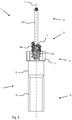
- FIG. 1 shows a perspective view of an embodiment of a connecting element according to the invention.
- the screw-in element 1 has a pin-shaped design and extends along a longitudinal axis L.
- a thread 100 is provided and at a second free end 11 a driving profile 110 in the form of a hexagon socket.
- the contact element 2 comprises at a first free end 20 a spring 200 and at a second free end a connecting pin 210.
- Das Contact element 2 is arranged with the spring 200 at the second free end 11 of the screw-1.
- FIG. 2A shows a schematic sectional view through the longitudinal axis L of an embodiment of a connecting element according to the invention, wherein on the right side a first embodiment of the Einschraubelements 1 is shown and on the left side a second embodiment.
- the first embodiment of the screw-1 comprises on its lateral surface 101, a thread 100 which extends from the first free end 10 and a receptacle 111, which extends from the second free end 11 at.
- the receptacle 111 is a spiral-shaped recess with a circular cross-section.
- the outer contour of the receptacle 111 is congruent with the inner contour of the spring 200 of the contact element 2.
- the thread 100 is formed finer than the receptacle 111.
- the thread 100 is formed identical to the receptacle 111 and extends from the first free end 10 to the second free end 11.
- the outer contour of the thread 100, respectively the receptacle 111 is congruent with the inner contour of the spring 200th Basically, all combinations of threads 100 and springs 200, in which the pitch of the thread 100 is the same size as the pitch of the spring 200.
- the FIG. 2B shows a combination of a thread 100, respectively a receptacle 111 with a shape of a pointed thread and a spring 200 with a spring wire having a circular cross-section.
- the Figure 2C shows a combination of a pointed thread 100 with a spring 200 with a spring wire with a trapezoidal cross-section.
- threads such as trapezoidal thread, round thread or flat thread as a receptacle 100 are possible.
- springs 200 can be used with spring wires with round, oval or polygonal cross sections.
- FIG. 3 shows a schematic sectional view of an alternative embodiment of a connecting element according to the invention.
- an outer profile 112 is provided as a driving profile, for example, a hexagonal profile.
- a fixing pin 113 is arranged with a peripheral receptacle 114, wherein the fixing pin 113 is formed integrally with the Einschraubelement 1 together.
- the peripheral receptacle 114 is a helical recess.
- the spring 200 of the contact element 2 is arranged in the peripheral receptacle 114.
- the outer contour of the receptacle 114 is congruent with the inner contour of the spring 200.
- FIG. 4 shows a schematic sectional view of an alternative embodiment of a connecting element according to the invention.
- the pin 113 is arranged in a central receptacle 115, which is formed on the front side at the second free end 11 of the screw-1.
- the central receptacle is a recess in the form of a bore.
- the pin 113 in turn comprises the peripheral receptacle 114 and the spring 200 is disposed in the peripheral receptacle 114.
- FIG. 5 shows a schematic sectional view of an alternative embodiment of a connecting element according to the invention.
- the Einschraubelement 1 comprises at the second free end 11 a peripheral driving profile 112 and a frontally arranged centric receptacle 115.
- the contact element 2 comprises at the first free end 20, the spring 200 and a fixing pin 201.
- the contact element 2 is connected to the mounting pin 201 in the central receptacle 115 of the screw-1 arranged.
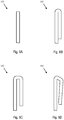
- FIGS. 6A-D show various embodiments of connecting pins 210 of inventive connecting elements. 2
- the FIG. 6A time a simple straight pin with a face at the free end.
- the free end may be rounded.
- FIG. 6B shows a simply bent pin, the two adjacent to the arc legs parallel and adjacent to each other.
- FIG. 6C shows a U-shaped pin, wherein the two adjoining the middle part legs parallel and spaced from each other and wherein the central part is aligned substantially perpendicular to the two legs.
- FIG. 6D shows a U-shaped pin, wherein the two adjacent to the middle part of the leg from the middle part converge away and wherein the middle part obliquely, that is not aligned at right angles to the two legs.
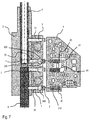
- FIG. 7 shows a schematic sectional view through an inventive connection arrangement.
- the arrangement comprises a first component 3, which is connected to connecting elements 1, 2 to a second component 4.
- the first component 3 comprises a first connection element 5, which is fixed with fastening elements 7 in the first component 3.
- Shown is a rack as connecting element 5, which may be, for example, the vertically displaceable Z-axis of a manipulator.
- the rack 5 is fixed with a threaded pin 7 in the housing of the first component 3.
- the threaded pin 7 is screwed into a threaded bore 31 of the housing of the first component 3.
- the one connecting element 1,2 is screwed into a further threaded bore 30, wherein the end face of the screw-1 is electrically conductive in contact with the rack 5.
- the further threaded bore 30 comprises on its side directed against the second component 4 a countersink 300 with a larger diameter than the portion of the further bore with the thread.
- the spring 200 of the contact element 2 is partially disposed in the countersink 300.
- the spring 200 and the connecting pin 210 project away from the first component 3.
- a second connection element 6 is fixed separately from the first connection element 5 in the housing of the first component 3 with a threaded pin 7 with an internal hexagon.
- a connecting element 1. 2 according to the invention is in electrical contact with the second connecting element 6.
- the second component 4 comprises bushes 40 in which the Connecting pins 210 of the contact element 2 are insertable to make an electrical contact.
- the second component 4 comprises connection elements 41, which are electrically connected to the sockets.
- the first connection element 5 of the first component 3 can be electrically connected to the second connection element 6 of the first component 3 by the connection elements 1, 2, the sockets 40 and the connection elements 41 of the second component 4.
Landscapes
- Engineering & Computer Science (AREA)
- Manufacturing & Machinery (AREA)
- Connections By Means Of Piercing Elements, Nuts, Or Screws (AREA)
- Measuring Leads Or Probes (AREA)
- Connections Arranged To Contact A Plurality Of Conductors (AREA)
- Details Of Connecting Devices For Male And Female Coupling (AREA)
Abstract
Description
- Die vorliegende Erfindung betrifft ein Verbindungselement, insbesondere ein elektrisches Verbindungselement.
- Aus dem Stand der Technik sind Verbindungselemente bekannt, welche beispielsweise einen Stift umfassen, welcher in eine entsprechende Stiftaufnahme lösbar eingeführt werden kann. Bei der Verwendung solcher Verbindungselemente ist die Einhaltung der Fertigungs- und Montagetoleranzen sehr wichtig, da sonst das Verbindungselement nicht mehr in eine entsprechende Buchse einführbar ist.
- Eine Aufgabe der vorliegenden Erfindung besteht darin, ein Verbindungselement bereitzustellen, welches auch bei grösseren Fertigungs- und Montagetoleranzen noch sicher in eine entsprechende Buchse einführbar ist.
- Diese Aufgabe wird durch ein Verbindungselement mit den Merkmalen des Anspruchs 1 gelöst. Weitere Ausführungsformen des Verbindungselements, sowie eine Verbindungsanordnung, sind durch die Merkmale von weiteren Ansprüchen definiert.
- Ein erfindungsgemässes Verbindungselement umfasst ein Einschraubelement und einem Kontaktelement, wobei das Einschraubelement stiftförmig ausgebildet ist und sich entlang einer Längsachse erstreckt. An seinem ersten freien Ende umfasst das Einschraubelement ein Gewinde und an seinem zweiten freien Ende ein Mitnahmeprofil und eine Aufnahme. Das Kontaktelement ist mit seinem ersten freien Ende in der Aufnahme angeordnet und an seinem zweiten freien Ende umfasst es einen Verbindungsstift, welcher in der Richtung der Längsachse über das Einschraubelement hinausragt. Das Kontaktelement umfasst eine Feder, welche zwischen dem Kontaktelement und dem Verbindungsstift angeordnet ist. Durch die Feder können fertigungsbedingte Ungenauigkeiten kompensiert werden. D.h. die Einschraubelemente müssen nicht exakt fluchtend mit den entsprechenden Buchsen ausgerichtet sein, damit die Kontaktelemente in die Buchsen einführbar sind.
- In einer Ausführungsform umfasst das Mitnahmeprofil des Einschraubelements ein Innenprofil, beispielsweise ein Innensechskant. Schlitz-, Kreuz- oder Torxprofile können jedoch auch vorgesehen sein. Die Aufnahme des Einschraubelements umfasst eine periphere Ausnehmung und wobei das erste freie Ende des Kontaktelements die Feder umfasst und mit der Feder in der peripheren Ausnehmung angeordnet ist. Der Querschnitt der peripheren Ausnehmung kann gleich dem Querschnitt der entsprechenden Feder sein. Alternativ können die Querschnitte unterschiedlich ausgestaltet sein. Beispielsweise kann die periphere Ausnehmung eine Spirale mit eckigem oder rundem Querschnitt sein. Die Feder kann ebenfalls eine Spiralfeder mit rundem oder eckigem Querschnitt sein.
- In einer Ausführungsform ist die periphere Ausnehmung identisch mit dem Gewinde und erstreckt sich über die gesamte Länge des Einschraubelements. Alternativ können die periphere Ausnehmung und das Gewinde unterschiedlich ausgestaltet sein. Beispielsweise kann die Spirale der peripheren Ausnehmung einen grösseren Querschnitt als diejenige des Gewindes umfassen.
- In einer Ausführungsform umfasst das Mitnahmeprofil des Einschraubelements ein Aussenprofil, wobei das Einschraubelement am zweiten freien Ende einen Befestigungsstift mit einer peripheren Aufnahme umfasst und wobei das erste freie Ende des Kontaktelements die Feder umfasst und mit der Feder in der peripheren Aufnahme angeordnet ist.
- In einer Ausführungsform ist der Befestigungsstift gemeinsam einstückig mit dem Einschraubelement ausgebildet.
- In einer Ausführungsform ist der Befestigungsstift in einer zentrischen Ausnehmung im Einschraubelement angeordnet.
- In einer Ausführungsform umfasst das Mitnahmeprofil des Einschraubelements ein Aussenprofil, wobei das Einschraubelement am zweiten freien Ende eine zentrische Aufnahme umfasst, wobei das erste freie Ende des Kontaktelements die Feder und einen Befestigungsstift umfasst und mit dem Befestigungsstift in der zentrischen Aufnahme angeordnet ist.
- In einer Ausführungsform ist die Kontur des Kontaktelements im Bereich der Aufnahme im Wesentlichen kongruent mit derjenigen der Aufnahme und stellt eine passgenaue Verbindung dar.
- In einer Ausführungsform erstreckt sich der Verbindungsstift im Wesentlichen entlang der Längsachse, in der Verlängerung der Längsmittelachse des Einschraubelements. Alternativ kann der Verbindungsstift versetzt zur Längsachse angeordnet ist und sich im Wesentlichen in der Richtung der Längsachse erstrecken. Der Verbindungsstift kann auch tangential zu einer Mantelfläche des Einschraubelements angeordnet sein.
- In einer Ausführungsform sind das Einschraubelement und das Kontaktelement aus einem elektrisch leitendenden Material ausgebildet und sind elektrisch wirkverbunden miteinander.
- Die erwähnten Ausführungsformen des Verbindungselements lassen sich in beliebiger Kombination einsetzen, sofern sie sich nicht widersprechen.
- Eine erfindungsgemässe Verbindungsanordnung umfasst ein erstes Bauteil, wobei das erste Bauteil mindestens eine Gewindebohrung umfasst, wobei in mindestens einer der Gewindebohrungen ein Verbindungselement gemäss einer der zuvor beschriebenen Ausführungsformen eingeschraubt ist.
- In einer Ausführungsform umfasst die Verbindungsanordnung weiter mindestens ein zweites Bauteil, wobei jedes zweite Bauteil mindestens eine Buchse umfasst, wobei der Verbindungsstift des mindestens einen Verbindungselements in der bestimmungsgemässen Gebrauchslage in der mindestens einen Buchse angeordnet ist.
- In einer Ausführungsform ist die Buchse derart ausgestaltet ist, dass Anschlusselemente des ersten Bauteils durch das Verbindungselement und die entsprechende Buchse mit Anschlusselementen des zweiten Bauteils elektrisch wirkverbindbar sind.
- In einer Ausführungsform ist eine Stirnseite am ersten freien Ende des Einschraubelements des jeweiligen Verbindungselements in einem elektrischen Kontakt mit dem entsprechenden Anschlusselement des ersten Bauteils.
- In einer Ausführungsform umfasst mindestens eine der Gewindebohrungen eine Senkung, in welche das Kontaktelement zumindest teilweise einführbar ist. Alternativ kann die Gewindebohrung ohne Senkung vorgesehen sein.
- Die erwähnten Ausführungsformen der Verbindungsanordnung lassen sich in beliebiger Kombination einsetzen, sofern sie sich nicht widersprechen.
- Ausführungsbeispiele der vorliegenden Erfindung werden nachstehend anhand von Figuren noch näher erläutert. Diese dienen lediglich zur Erläuterung und sind nicht einschränkend auszulegen. Es zeigen
-
Fig. 1 eine perspektivische Ansicht einer Ausführungsform eines erfindungsgemässen Verbindungselements; -
Fig. 2A eine schematische Schnittansicht durch die Längsachse einer Ausführungsform eines erfindungsgemässen Verbindungselements; -
Fig. 2B-C alternative Detailansichten derFigur 2A ; -
Fig. 3 eine schematische Schnittansicht einer alternativen Ausführungsform eines erfindungsgemässen Verbindungselements; -
Fig. 4 eine schematische Schnittansicht einer alternativen Ausführungsform eines erfindungsgemässen Verbindungselements; -
Fig. 5 eine schematische Schnittansicht einer alternativen Ausführungsform eines erfindungsgemässen Verbindungselements; -
Fig. 6A-D verschiedene Ausführungsformen von Verbindungsstiften von erfindungsgemässen Verbindungselementen; und -
Fig. 7 eine schematische Schnittansicht durch eine erfindungsgemässe Verbindungsanordnung. - Die
Figur 1 zeigt eine perspektivische Ansicht einer Ausführungsform eines erfindungsgemässen Verbindungselements. Das Verbindungselement umfasst ein Einschraubelement 1 und ein am Einschraubelement 1 angeordnetes Kontaktelement 2. Das Einschraubelement 1 ist stiftförmig ausgebildet und erstreckt sich entlang einer Längsachse L. An einem ersten freien Ende 10 des Einschraubelements 1 ist ein Gewinde 100 vorgesehen und an einem zweiten freien Ende 11 ein Mitnahmeprofil 110 in der Form eines Innensechskants. Das Kontaktelement 2 umfasst an einem ersten freien Ende 20 eine Feder 200 und an einem zweiten freien Ende einen Verbindungsstift 210. Das Kontaktelement 2 ist mit der Feder 200 am zweiten freien ende 11 des Einschraubelements 1 angeordnet. - Die
Figur 2A zeigt eine schematische Schnittansicht durch die Längsachse L einer Ausführungsform eines erfindungsgemässen Verbindungselements, wobei auf der rechten Seite eine erste Ausführungsform des Einschraubelements 1 gezeigt ist und auf der linken Seite eine zweite Ausführungsform. Die erste Ausführungsform des Einschraubelements 1 umfasst an seiner Mantelfläche 101 ein Gewinde 100, welches sich vom ersten freien Ende 10 an erstreckt und eine Aufnahme 111, welche sich vom zweiten freien Ende 11 an erstreckt. Die Aufnahme 111 ist eine spiralenförmige Ausnehmung mit einem kreisrunden Querschnitt. Die Aussenkontur der Aufnahme 111 ist kongruent mit der Innenkontur der Feder 200 des Kontaktelements 2. Das Gewinde 100 ist feiner ausgebildet als die Aufnahme 111. Am zweiten freien Ende ist ein Innenprofil 110 vorgesehen. Bei der zweiten Ausführungsform des Einschraubelements 1 ist das Gewinde 100 identisch mit der Aufnahme 111 ausgebildet und erstreckt sich vom ersten freien Ende 10 bis zum zweiten freien Ende 11. Die Aussenkontur des Gewindes 100, respektive der Aufnahme 111 ist kongruent mit der Innenkontur der Feder 200 des Kontaktelements 2. Grundsätzlich eignen sich alle Kombinationen von Gewinden 100 und Federn 200, bei welchen die Ganghöhe des Gewindes 100 gleichgross ist wie die Ganghöhe der Feder 200. DieFigur 2B zeigt eine Kombination von einem Gewinde 100, respektive einer Aufnahme 111 mit einer Form eines Spitzgewindes und einer Feder 200 mit einem Federdraht mit einem kreisrunden Querschnitt. DieFigur 2C zeigt eine Kombination von einem Spitzgewinde 100 mit einer Feder 200 mit einem Federdraht mit einem trapezoiden Querschnitt. Grundsätzlich sind alle bekannten Gewindearten, wie beispielsweise Trapezgewinde, Rundgewinde oder Flachgewinde als Aufnahme 100 möglich. Ebenfalls können Federn 200 mit Federdrähten mit runden, ovalen oder mehreckigen Querschnitten eingesetzt werden. - Die
Figur 3 zeigt eine schematische Schnittansicht einer alternativen Ausführungsform eines erfindungsgemässen Verbindungselements. Am zweiten freien Ende 11 des Einschraubelements 1 ist ein Aussenprofil 112 als Mitnahmeprofil vorgesehen, beispielsweise ein Sechskantprofil. An dieses anschliessend ist ein Befestigungsstift 113 mit einer peripheren Aufnahme 114 angeordnet, wobei der Befestigungsstift 113 gemeinsam einstückig mit dem Einschraubelement 1 ausgebildet ist. Die periphere Aufnahme 114 ist eine spiralförmige Ausnehmung. Die Feder 200 des Kontaktelements 2 ist in der peripheren Aufnahme 114 angeordnet. Die Aussenkontur der Aufnahme 114 ist kongruent mit der Innenkontur der Feder 200. - Die
Figur 4 zeigt eine schematische Schnittansicht einer alternativen Ausführungsform eines erfindungsgemässen Verbindungselements. Im Unterschied zur Ausführungsform derFigur 3 , ist der Stift 113 in einer zentrischen Aufnahme 115 angeordnet, welche stirnseitig am zweiten freien Ende 11 des Einschraubelements 1 ausgebildet ist. Die zentrische Aufnahme ist eine Ausnehmung in der Form einer Bohrung. Der Stift 113 umfasst wiederum die periphere Aufnahme 114 und die Feder 200 ist in der peripheren Aufnahme 114 angeordnet. - Die
Figur 5 zeigt eine schematische Schnittansicht einer alternativen Ausführungsform eines erfindungsgemässen Verbindungselements. Das Einschraubelement 1 umfasst am zweiten freien Ende 11 ein peripheres Mitnahmeprofil 112 und eine stirnseitig angeordnete zentrische Aufnahme 115. Das Kontaktelement 2 umfasst am ersten freien Ende 20 die Feder 200 und einen Befestigungsstift 201. Das Kontaktelement 2 ist mit dem Befestigungsstift 201 in der zentrischen Aufnahme 115 des Einschraubelements 1 angeordnet. - Die
Figuren 6A-D zeigen verschiedene Ausführungsformen von Verbindungsstiften 210 von erfindungsgemässen Verbindungselementen 2. - Die
Figur 6A zeit einen einfachen geraden Stift mit einer Stirnfläche am freien Ende. Alternativ kann das freie Ende gerundet ausgebildet sein. - Die
Figur 6B zeigt einen einfach umgebogenen Stift, wobei die beiden an den Bogen anschliessenden Schenkel parallel und aneinander anliegend verlaufen. - Die
Figur 6C zeigt einen U-förmigen Stift, wobei die beiden an den Mittelteil anschliessenden Schenkel parallel und beabstandet zueinander verlaufen und wobei der Mittelteil im Wesentlichen senkrecht zu den beiden Schenkel ausgerichtet ist. - Die
Figur 6D zeigt einen U-förmigen Stift, wobei die beiden an den Mittelteil anschliessenden Schenkel vom Mittelteil weg zusammenlaufen und wobei der Mittelteil schräg, d.h. nicht rechtwinklig zu den beiden Schenkel ausgerichtet ist. - Die
Figur 7 zeigt eine schematische Schnittansicht durch eine erfindungsgemässe Verbindungsanordnung. Die Anordnung umfasst ein erstes Bauteil 3, welches mit Verbindungselementen 1,2 mit einem zweiten Bauteil 4 verbunden ist. Das erste Bauteil 3 umfasst ein erstes Anschlusselement 5, welches mit Befestigungselementen 7 im ersten Bauteil 3 fixiert ist. Dargestellt ist eine Zahnstange als Anschlusselement 5, welche beispielsweise die vertikal verschiebbare Z-Achse eines Manipulators sein kann. Die Zahnstange 5 ist mit einem Gewindestift 7 im Gehäuse des ersten Bauteils 3 fixiert. Der Gewindestift 7 ist in einer Gewindebohrung 31 des Gehäuses des ersten Bauteils 3 eingeschraubt. Das ein Verbindungselement 1,2 ist in einer weiteren Gewindebohrung 30 eingeschraubt, wobei die Stirnseite des Einschraubelements 1 elektrisch leitend im Kontakt mit der Zahnstange 5 steht. Die weitere Gewindebohrung 30 umfasst auf ihrer gegen das zweite Bauteil 4 gerichteten Seite eine Senkung 300 mit einem grösseren Durchmesser als der Abschnitt der weiteren Bohrung mit dem Gewinde. Die Feder 200 des Kontaktelements 2 ist teilweise in der Senkung 300 angeordnet. Die Feder 200 und der Verbindungsstift 210 ragen vom ersten Bauteil 3 weg. Ein zweites Anschlusselement 6 ist getrennt vom ersten Anschlusselement 5 im Gehäuse des ersten Bauteils 3 mit einem Gewindestift 7 mit einem Innensechskant fixiert. Ein erfindungsgemässes Verbindungselement 1,2 steht im elektrischen Kontakt mit dem zweiten Anschlusselement 6. Das zweite Bauteil 4 umfasst Buchsen 40 in welche die Verbindungsstifte 210 des Kontaktelements 2 einführbar sind, um einen elektrischen Kontakt herzustellen. Weiter umfasst das zweite Bauteil 4 Anschlusselemente 41, welche mit den Buchsen elektrisch verbunden sind. Das erste Anschlusselement 5 des ersten Bauteils 3 ist durch die Verbindungselemente 1,2, die Buchsen 40 und die Anschlusselemente 41 des zweiten Bauteils 4 mit dem zweiten Anschlusselement 6 des ersten Bauteils 3 elektrisch verbindbar.BEZUGSZEICHENLISTE 1 Einschraubelement 21 zweites freies Ende 10 erstes freies Ende 210 Verbindungsstift 100 Gewinde 3 erstes Bauteil 101 Mantelfläche 30 Gewindebohrung 11 zweites freies Ende 300 Senkung 110 zentrisches Mitnahmeprofil 31 Gewindebohrung 4 zweites Bauteil 111 periphere Aufnahme 40 Buchse 112 peripheres Mitnahmeprofil 41 Anschlusselement 113 Stift 5 erstes Anschlusselement 114 periphere Aufnahme 6 zweites 115 zentrische Aufnahme Anschlusselement 2 Kontaktelement 7 Befestigungselement 20 erstes freies Ende 200 Feder L Längsachse 201 Befestigungsstift
Claims (14)
- Ein Verbindungselement mit einem Einschraubelement (1) und einem Kontaktelement (2), wobei das Einschraubelement (1) stiftförmig entlang einer Längsachse (L) ausgebildet ist, an seinem ersten freien Ende (10) ein Gewinde (100) umfasst und an seinem zweiten freien Ende (11) ein Mitnahmeprofil (110,112) und eine Aufnahme (111,114;115) umfasst, wobei das Kontaktelement (2) mit seinem ersten freien Ende (20) in der Aufnahme (111,114;115) angeordnet ist und an seinem zweiten freien Ende (21) einen Verbindungsstift (210) umfasst, welcher in der Richtung der Längsachse (L) über das Einschraubelement (1) hinausragt, dadurch gekennzeichnet, dass das Kontaktelement (2) eine Feder (200) umfasst, welche zwischen dem Kontaktelement (2) und dem Verbindungsstift (210) angeordnet ist.
- Das Verbindungselement gemäss Anspruch 1, wobei das Mitnahmeprofil des Einschraubelements (1) ein Innenprofil (110) umfasst, wobei die Aufnahme des Einschraubelements (1) eine periphere Aufnahme (111) umfasst und wobei das erste freie Ende (20) des Kontaktelements (2) die Feder (200) umfasst und mit der Feder (200) in der peripheren Aufnahme (111) angeordnet ist.
- Das Verbindungselement gemäss 2, wobei die periphere Aufnahme (111) identisch mit dem Gewinde (100) ist und sich über die gesamte Länge des Einschraubelements (1) erstreckt.
- Das Verbindungselement gemäss Anspruch 1, wobei das Mitnahmeprofil des Einschraubelements (1) ein Aussenprofil (112) umfasst, wobei das Einschraubelement (1) am zweiten freien Ende (11) einen Befestigungsstift (113) mit einer peripheren Aufnahme (114) umfasst und wobei das erste freie Ende (20) des Kontaktelements (2) die Feder (200) umfasst und mit der Feder (200) in der peripheren Aufnahme (114) angeordnet ist.
- Das Verbindungselement gemäss Anspruch 3, wobei der Befestigungsstift (113) gemeinsam einstückig mit dem Einschraubelement (1) ausgebildet ist.
- Das Verbindungselement gemäss Anspruch 3, wobei der Befestigungsstift (113) in einer zentrischen Aufnahme (115) im Einschraubelement (1) angeordnet ist.
- Das Verbindungselement gemäss Anspruch 1, wobei das Mitnahmeprofil des Einschraubelements (1) ein Aussenprofil (112) umfasst, wobei das Einschraubelement (1) am zweiten freien Ende (11) eine zentrische Aufnahme (115) umfasst, wobei das erste freie Ende (20) des Kontaktelements (2) die Feder (200) und einen Befestigungsstift (201) umfasst und mit dem Befestigungsstift (201) in der zentrischen Aufnahme (115) angeordnet ist.
- Das Verbindungselement gemäss einem der vorangehenden Ansprüche, wobei die Kontur des Kontaktelements (2) im Bereich der Aufnahme (111,114;115) im Wesentlichen kongruent mit dieser ausgebildet ist und eine passgenaue Verbindung darstellt.
- Das Verbindungselement gemäss einem der vorangehenden Ansprüche, wobei das Einschraubelement (1) und das Kontaktelement (2) aus einem elektrisch leitendenden Material ausgebildet sind und miteinander elektrisch wirkverbunden sind.
- Eine Verbindungsanordnung umfassend ein erstes Bauteil (3), wobei das erste Bauteil (3) mindestens eine Gewindebohrung (30,31) umfasst, dadurch gekennzeichnet, dass in mindestens einer der Gewindebohrungen (30) ein Verbindungselement gemäss einem der Ansprüche 1 bis 9 eingeschraubt ist.
- Die Verbindungsanordnung gemäss Anspruch 10, weiter umfassend mindestens ein zweites Bauteil (4), wobei jedes zweite Bauteil (4) mindestens eine Buchse (40) umfasst, wobei der Verbindungsstift (210) des mindestens einen Verbindungselements in der bestimmungsgemässen Gebrauchslage in der mindestens einen Buchse (40) angeordnet ist.
- Die Verbindungsanordnung gemäss Anspruch 10 oder 11, wobei die Buchse (40) derart ausgestaltet ist, dass Anschlusselemente (5,6) des ersten Bauteils (3) durch das Verbindungselement und die Buchse (40) mit Anschlusselementen (41) des zweiten Bauteils (4) elektrisch wirkverbindbar sind.
- Die Verbindungsanordnung gemäss Anspruch 12, wobei eine Stirnseite am ersten freien Ende (10) des Einschraubelements (1) des jeweiligen Verbindungselements in einem elektrischen Kontakt mit dem entsprechenden Anschlusselement (5,6) des ersten Bauteils (3) ist.
- Die Verbindungsanordnung gemäss einem der Ansprüche 10 bis 13, wobei mindestens eine der Gewindebohrungen (30) eine Senkung (300) umfasst, in welche das Kontaktelement (2) zumindest teilweise einführbar ist.
Priority Applications (3)
| Application Number | Priority Date | Filing Date | Title |
|---|---|---|---|
| EP18166127.3A EP3550672B1 (de) | 2018-04-06 | 2018-04-06 | Verbindungselement |
| US16/373,073 US10530087B2 (en) | 2018-04-06 | 2019-04-02 | Connecting element |
| CN201910271011.6A CN110350374B (zh) | 2018-04-06 | 2019-04-04 | 连接元件和连接组件 |
Applications Claiming Priority (1)
| Application Number | Priority Date | Filing Date | Title |
|---|---|---|---|
| EP18166127.3A EP3550672B1 (de) | 2018-04-06 | 2018-04-06 | Verbindungselement |
Publications (2)
| Publication Number | Publication Date |
|---|---|
| EP3550672A1 true EP3550672A1 (de) | 2019-10-09 |
| EP3550672B1 EP3550672B1 (de) | 2021-08-04 |
Family
ID=61913010
Family Applications (1)
| Application Number | Title | Priority Date | Filing Date |
|---|---|---|---|
| EP18166127.3A Active EP3550672B1 (de) | 2018-04-06 | 2018-04-06 | Verbindungselement |
Country Status (3)
| Country | Link |
|---|---|
| US (1) | US10530087B2 (de) |
| EP (1) | EP3550672B1 (de) |
| CN (1) | CN110350374B (de) |
Citations (4)
| Publication number | Priority date | Publication date | Assignee | Title |
|---|---|---|---|---|
| US6565395B1 (en) * | 2001-12-21 | 2003-05-20 | Northrop Grumman Corporation | Electrical connection to a coil spring through a local interference fit for connection to a vibratory rotation sensor and method of forming the same |
| US7677901B1 (en) * | 2008-12-26 | 2010-03-16 | Yamaichi Electronics Co., Ltd. | Electric connecting apparatus for semiconductor devices and contact used therefor |
| DE102014211003A1 (de) * | 2014-06-10 | 2015-12-17 | Robert Bosch Gmbh | Anordnung zur elektrischen Kontaktierung eines ersten Kontaktpartners und eines zweiten Kontaktpartners |
| GB2539702A (en) * | 2015-06-25 | 2016-12-28 | Alstom Technology Ltd | Power converter sub-module |
Family Cites Families (21)
| Publication number | Priority date | Publication date | Assignee | Title |
|---|---|---|---|---|
| US3058083A (en) * | 1960-01-29 | 1962-10-09 | Burroughs Corp | Electrical connector |
| US3503033A (en) * | 1967-12-12 | 1970-03-24 | Gen Electric | Coil spring connector |
| US4192567A (en) * | 1978-05-08 | 1980-03-11 | William Gomolka | Electrical connector |
| US5038467A (en) * | 1989-11-09 | 1991-08-13 | Advanced Interconnections Corporation | Apparatus and method for installation of multi-pin components on circuit boards |
| US6155846A (en) * | 2000-01-03 | 2000-12-05 | Motorola, Inc. | Electrical contactor assembly |
| JP2004007156A (ja) * | 2002-05-31 | 2004-01-08 | Matsushita Electric Ind Co Ltd | コンデンサマイクロホン |
| AT9304U1 (de) * | 2006-06-13 | 2007-07-15 | Pc Electric Gmbh | Leiteranschlussklemme und elektrische steckvorrichtung |
| US7796397B2 (en) * | 2006-08-23 | 2010-09-14 | Panasonic Corporation | Electronic components assembly and method for producing same |
| JP2011507162A (ja) * | 2007-12-06 | 2011-03-03 | バル・シール・エンジニアリング | インラインコネクタ |
| JP2009146820A (ja) * | 2007-12-17 | 2009-07-02 | Hosiden Corp | コンタクト及び接続装置 |
| US20090259264A1 (en) * | 2008-04-14 | 2009-10-15 | Alfred E. Mann Foundation For Scientific Research | Surgically implantable wire connector |
| CN201436716U (zh) * | 2008-10-16 | 2010-04-07 | 上海华伦仪表电子有限公司 | 一种大电流连接器 |
| DE202009003592U1 (de) * | 2009-03-13 | 2009-05-20 | Rosenberger Hochfrequenztechnik Gmbh & Co. Kg | Abdichtung eines gefederten Kontaktstiftes |
| US20100267291A1 (en) * | 2009-04-20 | 2010-10-21 | Scott Chabineau-Lovgren | Swaging process for improved compliant contact electrical test performance |
| US20110059661A1 (en) * | 2009-09-08 | 2011-03-10 | Denso Corporation | Electrical connector assembly for connecting printed circuit board and electrical component, and electric device |
| CN101908695B (zh) * | 2010-06-21 | 2011-12-21 | 贵州航天电器股份有限公司 | 一种气电混装分离连接器 |
| TWI424624B (zh) * | 2011-09-05 | 2014-01-21 | Frank Hayama | Conductive element and its preparation method |
| CN105009381B (zh) * | 2013-02-15 | 2017-05-17 | 马尔遆公开股份有限公司 | 用于接触母线的装置 |
| CH708837A1 (de) * | 2013-11-14 | 2015-05-15 | Kistler Holding Ag | Piezoelektrischer Kraftsensor mit lösbarer elektrischer Verbindung zwischen Elektrode und Kontaktpin. |
| US9748678B2 (en) * | 2015-03-31 | 2017-08-29 | Sensata Technologies, Inc. | Connectivity in an assembly |
| GB2546081B (en) * | 2016-01-06 | 2019-08-14 | Amphenol Ltd | Pin for adapting electrical connectors, and a kit of parts inlcuding same |
-
2018
- 2018-04-06 EP EP18166127.3A patent/EP3550672B1/de active Active
-
2019
- 2019-04-02 US US16/373,073 patent/US10530087B2/en active Active
- 2019-04-04 CN CN201910271011.6A patent/CN110350374B/zh active Active
Patent Citations (4)
| Publication number | Priority date | Publication date | Assignee | Title |
|---|---|---|---|---|
| US6565395B1 (en) * | 2001-12-21 | 2003-05-20 | Northrop Grumman Corporation | Electrical connection to a coil spring through a local interference fit for connection to a vibratory rotation sensor and method of forming the same |
| US7677901B1 (en) * | 2008-12-26 | 2010-03-16 | Yamaichi Electronics Co., Ltd. | Electric connecting apparatus for semiconductor devices and contact used therefor |
| DE102014211003A1 (de) * | 2014-06-10 | 2015-12-17 | Robert Bosch Gmbh | Anordnung zur elektrischen Kontaktierung eines ersten Kontaktpartners und eines zweiten Kontaktpartners |
| GB2539702A (en) * | 2015-06-25 | 2016-12-28 | Alstom Technology Ltd | Power converter sub-module |
Also Published As
| Publication number | Publication date |
|---|---|
| US10530087B2 (en) | 2020-01-07 |
| CN110350374A (zh) | 2019-10-18 |
| CN110350374B (zh) | 2024-05-28 |
| US20190312370A1 (en) | 2019-10-10 |
| EP3550672B1 (de) | 2021-08-04 |
Similar Documents
| Publication | Publication Date | Title |
|---|---|---|
| DE112012007184B4 (de) | Wellenendadapter und Kugelrollspindelaufbau | |
| DE102014118726B4 (de) | Kopplungsanordnung mit einer Fließbohrschraube | |
| DE102008058204A1 (de) | Steckbuchse | |
| DE202019106844U1 (de) | Anzugelement | |
| DE2239476A1 (de) | Elektrischer verbinder und verfahren zur herstellung einer verbindung | |
| DE102020004179A1 (de) | Werkzeugansatzstelle mit Ausrichthilfe | |
| DE102025112026A1 (de) | Eine Mehrkantschraube sowie ein Verfahren zur Verwendung einer solchen Mehrkantschraube | |
| EP3550672B1 (de) | Verbindungselement | |
| EP3828426B1 (de) | Verbindungselement für mehrkantrohre | |
| DE102005057996A1 (de) | Wurzelkanalinstrument | |
| EP2590493A2 (de) | Frequenzumrichter | |
| DE202022102662U1 (de) | Steckschlüsseleinsatz und Werkzeuganordnung | |
| DE20104307U1 (de) | Dehnschraube | |
| EP1416588A1 (de) | Kabelstecker | |
| DE202015104842U1 (de) | Gewindeverbindung und Bohrgestänge mit Gewindeverbindung | |
| DE8202339U1 (de) | Schraube | |
| WO2006086970A1 (de) | Verbindereinrichtung für profile | |
| DE202008001361U1 (de) | Dübelbolzen einer Verbindungsvorrichtung | |
| DE538098C (de) | Drahtbefestigung an elektrischen Steckern, Steckdosen u. dgl. | |
| DE202022105117U1 (de) | Elektromotoranordnung | |
| DE102023101082A1 (de) | Verbindung eines Gewindestifts mit einem Befestigungselement | |
| DE10300650B3 (de) | Verbindungselement für einen Handlauf | |
| DE10237955A1 (de) | Druckfeder | |
| DE2516142B2 (de) | Drehkippgelenk fuer leuchten | |
| DE202017102910U1 (de) | Geräteanschluss |
Legal Events
| Date | Code | Title | Description |
|---|---|---|---|
| PUAI | Public reference made under article 153(3) epc to a published international application that has entered the european phase |
Free format text: ORIGINAL CODE: 0009012 |
|
| STAA | Information on the status of an ep patent application or granted ep patent |
Free format text: STATUS: THE APPLICATION HAS BEEN PUBLISHED |
|
| AK | Designated contracting states |
Kind code of ref document: A1 Designated state(s): AL AT BE BG CH CY CZ DE DK EE ES FI FR GB GR HR HU IE IS IT LI LT LU LV MC MK MT NL NO PL PT RO RS SE SI SK SM TR |
|
| AX | Request for extension of the european patent |
Extension state: BA ME |
|
| STAA | Information on the status of an ep patent application or granted ep patent |
Free format text: STATUS: REQUEST FOR EXAMINATION WAS MADE |
|
| 17P | Request for examination filed |
Effective date: 20200403 |
|
| RBV | Designated contracting states (corrected) |
Designated state(s): AL AT BE BG CH CY CZ DE DK EE ES FI FR GB GR HR HU IE IS IT LI LT LU LV MC MK MT NL NO PL PT RO RS SE SI SK SM TR |
|
| GRAP | Despatch of communication of intention to grant a patent |
Free format text: ORIGINAL CODE: EPIDOSNIGR1 |
|
| STAA | Information on the status of an ep patent application or granted ep patent |
Free format text: STATUS: GRANT OF PATENT IS INTENDED |
|
| RIC1 | Information provided on ipc code assigned before grant |
Ipc: H01R 4/36 20060101ALI20210208BHEP Ipc: H01R 13/631 20060101ALN20210208BHEP Ipc: H01R 12/53 20110101ALN20210208BHEP Ipc: H01R 13/24 20060101AFI20210208BHEP |
|
| RIC1 | Information provided on ipc code assigned before grant |
Ipc: H01R 13/631 20060101ALN20210215BHEP Ipc: H01R 4/36 20060101ALI20210215BHEP Ipc: H01R 12/53 20110101ALN20210215BHEP Ipc: H01R 13/24 20060101AFI20210215BHEP |
|
| RIC1 | Information provided on ipc code assigned before grant |
Ipc: H01R 12/53 20110101ALN20210225BHEP Ipc: H01R 13/631 20060101ALN20210225BHEP Ipc: H01R 13/24 20060101AFI20210225BHEP Ipc: H01R 4/36 20060101ALI20210225BHEP |
|
| INTG | Intention to grant announced |
Effective date: 20210316 |
|
| GRAS | Grant fee paid |
Free format text: ORIGINAL CODE: EPIDOSNIGR3 |
|
| GRAA | (expected) grant |
Free format text: ORIGINAL CODE: 0009210 |
|
| STAA | Information on the status of an ep patent application or granted ep patent |
Free format text: STATUS: THE PATENT HAS BEEN GRANTED |
|
| AK | Designated contracting states |
Kind code of ref document: B1 Designated state(s): AL AT BE BG CH CY CZ DE DK EE ES FI FR GB GR HR HU IE IS IT LI LT LU LV MC MK MT NL NO PL PT RO RS SE SI SK SM TR |
|
| REG | Reference to a national code |
Ref country code: GB Ref legal event code: FG4D Free format text: NOT ENGLISH |
|
| REG | Reference to a national code |
Ref country code: AT Ref legal event code: REF Ref document number: 1417963 Country of ref document: AT Kind code of ref document: T Effective date: 20210815 |
|
| REG | Reference to a national code |
Ref country code: CH Ref legal event code: EP |
|
| REG | Reference to a national code |
Ref country code: DE Ref legal event code: R096 Ref document number: 502018006391 Country of ref document: DE |
|
| REG | Reference to a national code |
Ref country code: IE Ref legal event code: FG4D Free format text: LANGUAGE OF EP DOCUMENT: GERMAN |
|
| REG | Reference to a national code |
Ref country code: LT Ref legal event code: MG9D |
|
| REG | Reference to a national code |
Ref country code: NL Ref legal event code: MP Effective date: 20210804 |
|
| PG25 | Lapsed in a contracting state [announced via postgrant information from national office to epo] |
Ref country code: SE Free format text: LAPSE BECAUSE OF FAILURE TO SUBMIT A TRANSLATION OF THE DESCRIPTION OR TO PAY THE FEE WITHIN THE PRESCRIBED TIME-LIMIT Effective date: 20210804 Ref country code: RS Free format text: LAPSE BECAUSE OF FAILURE TO SUBMIT A TRANSLATION OF THE DESCRIPTION OR TO PAY THE FEE WITHIN THE PRESCRIBED TIME-LIMIT Effective date: 20210804 Ref country code: HR Free format text: LAPSE BECAUSE OF FAILURE TO SUBMIT A TRANSLATION OF THE DESCRIPTION OR TO PAY THE FEE WITHIN THE PRESCRIBED TIME-LIMIT Effective date: 20210804 Ref country code: FI Free format text: LAPSE BECAUSE OF FAILURE TO SUBMIT A TRANSLATION OF THE DESCRIPTION OR TO PAY THE FEE WITHIN THE PRESCRIBED TIME-LIMIT Effective date: 20210804 Ref country code: ES Free format text: LAPSE BECAUSE OF FAILURE TO SUBMIT A TRANSLATION OF THE DESCRIPTION OR TO PAY THE FEE WITHIN THE PRESCRIBED TIME-LIMIT Effective date: 20210804 Ref country code: NO Free format text: LAPSE BECAUSE OF FAILURE TO SUBMIT A TRANSLATION OF THE DESCRIPTION OR TO PAY THE FEE WITHIN THE PRESCRIBED TIME-LIMIT Effective date: 20211104 Ref country code: PT Free format text: LAPSE BECAUSE OF FAILURE TO SUBMIT A TRANSLATION OF THE DESCRIPTION OR TO PAY THE FEE WITHIN THE PRESCRIBED TIME-LIMIT Effective date: 20211206 Ref country code: BG Free format text: LAPSE BECAUSE OF FAILURE TO SUBMIT A TRANSLATION OF THE DESCRIPTION OR TO PAY THE FEE WITHIN THE PRESCRIBED TIME-LIMIT Effective date: 20211104 Ref country code: LT Free format text: LAPSE BECAUSE OF FAILURE TO SUBMIT A TRANSLATION OF THE DESCRIPTION OR TO PAY THE FEE WITHIN THE PRESCRIBED TIME-LIMIT Effective date: 20210804 |
|
| PG25 | Lapsed in a contracting state [announced via postgrant information from national office to epo] |
Ref country code: PL Free format text: LAPSE BECAUSE OF FAILURE TO SUBMIT A TRANSLATION OF THE DESCRIPTION OR TO PAY THE FEE WITHIN THE PRESCRIBED TIME-LIMIT Effective date: 20210804 Ref country code: LV Free format text: LAPSE BECAUSE OF FAILURE TO SUBMIT A TRANSLATION OF THE DESCRIPTION OR TO PAY THE FEE WITHIN THE PRESCRIBED TIME-LIMIT Effective date: 20210804 Ref country code: GR Free format text: LAPSE BECAUSE OF FAILURE TO SUBMIT A TRANSLATION OF THE DESCRIPTION OR TO PAY THE FEE WITHIN THE PRESCRIBED TIME-LIMIT Effective date: 20211105 |
|
| PG25 | Lapsed in a contracting state [announced via postgrant information from national office to epo] |
Ref country code: NL Free format text: LAPSE BECAUSE OF FAILURE TO SUBMIT A TRANSLATION OF THE DESCRIPTION OR TO PAY THE FEE WITHIN THE PRESCRIBED TIME-LIMIT Effective date: 20210804 |
|
| PG25 | Lapsed in a contracting state [announced via postgrant information from national office to epo] |
Ref country code: DK Free format text: LAPSE BECAUSE OF FAILURE TO SUBMIT A TRANSLATION OF THE DESCRIPTION OR TO PAY THE FEE WITHIN THE PRESCRIBED TIME-LIMIT Effective date: 20210804 |
|
| REG | Reference to a national code |
Ref country code: DE Ref legal event code: R097 Ref document number: 502018006391 Country of ref document: DE |
|
| PG25 | Lapsed in a contracting state [announced via postgrant information from national office to epo] |
Ref country code: SM Free format text: LAPSE BECAUSE OF FAILURE TO SUBMIT A TRANSLATION OF THE DESCRIPTION OR TO PAY THE FEE WITHIN THE PRESCRIBED TIME-LIMIT Effective date: 20210804 Ref country code: SK Free format text: LAPSE BECAUSE OF FAILURE TO SUBMIT A TRANSLATION OF THE DESCRIPTION OR TO PAY THE FEE WITHIN THE PRESCRIBED TIME-LIMIT Effective date: 20210804 Ref country code: RO Free format text: LAPSE BECAUSE OF FAILURE TO SUBMIT A TRANSLATION OF THE DESCRIPTION OR TO PAY THE FEE WITHIN THE PRESCRIBED TIME-LIMIT Effective date: 20210804 Ref country code: EE Free format text: LAPSE BECAUSE OF FAILURE TO SUBMIT A TRANSLATION OF THE DESCRIPTION OR TO PAY THE FEE WITHIN THE PRESCRIBED TIME-LIMIT Effective date: 20210804 Ref country code: CZ Free format text: LAPSE BECAUSE OF FAILURE TO SUBMIT A TRANSLATION OF THE DESCRIPTION OR TO PAY THE FEE WITHIN THE PRESCRIBED TIME-LIMIT Effective date: 20210804 Ref country code: AL Free format text: LAPSE BECAUSE OF FAILURE TO SUBMIT A TRANSLATION OF THE DESCRIPTION OR TO PAY THE FEE WITHIN THE PRESCRIBED TIME-LIMIT Effective date: 20210804 |
|
| PLBE | No opposition filed within time limit |
Free format text: ORIGINAL CODE: 0009261 |
|
| STAA | Information on the status of an ep patent application or granted ep patent |
Free format text: STATUS: NO OPPOSITION FILED WITHIN TIME LIMIT |
|
| 26N | No opposition filed |
Effective date: 20220506 |
|
| PG25 | Lapsed in a contracting state [announced via postgrant information from national office to epo] |
Ref country code: IT Free format text: LAPSE BECAUSE OF FAILURE TO SUBMIT A TRANSLATION OF THE DESCRIPTION OR TO PAY THE FEE WITHIN THE PRESCRIBED TIME-LIMIT Effective date: 20210804 |
|
| PG25 | Lapsed in a contracting state [announced via postgrant information from national office to epo] |
Ref country code: SI Free format text: LAPSE BECAUSE OF FAILURE TO SUBMIT A TRANSLATION OF THE DESCRIPTION OR TO PAY THE FEE WITHIN THE PRESCRIBED TIME-LIMIT Effective date: 20210804 |
|
| REG | Reference to a national code |
Ref country code: BE Ref legal event code: MM Effective date: 20220430 |
|
| PG25 | Lapsed in a contracting state [announced via postgrant information from national office to epo] |
Ref country code: MC Free format text: LAPSE BECAUSE OF FAILURE TO SUBMIT A TRANSLATION OF THE DESCRIPTION OR TO PAY THE FEE WITHIN THE PRESCRIBED TIME-LIMIT Effective date: 20210804 Ref country code: LU Free format text: LAPSE BECAUSE OF NON-PAYMENT OF DUE FEES Effective date: 20220406 |
|
| PG25 | Lapsed in a contracting state [announced via postgrant information from national office to epo] |
Ref country code: BE Free format text: LAPSE BECAUSE OF NON-PAYMENT OF DUE FEES Effective date: 20220430 |
|
| PG25 | Lapsed in a contracting state [announced via postgrant information from national office to epo] |
Ref country code: IE Free format text: LAPSE BECAUSE OF NON-PAYMENT OF DUE FEES Effective date: 20220406 |
|
| P01 | Opt-out of the competence of the unified patent court (upc) registered |
Effective date: 20230522 |
|
| PG25 | Lapsed in a contracting state [announced via postgrant information from national office to epo] |
Ref country code: HU Free format text: LAPSE BECAUSE OF FAILURE TO SUBMIT A TRANSLATION OF THE DESCRIPTION OR TO PAY THE FEE WITHIN THE PRESCRIBED TIME-LIMIT; INVALID AB INITIO Effective date: 20180406 |
|
| PG25 | Lapsed in a contracting state [announced via postgrant information from national office to epo] |
Ref country code: MK Free format text: LAPSE BECAUSE OF FAILURE TO SUBMIT A TRANSLATION OF THE DESCRIPTION OR TO PAY THE FEE WITHIN THE PRESCRIBED TIME-LIMIT Effective date: 20210804 Ref country code: CY Free format text: LAPSE BECAUSE OF FAILURE TO SUBMIT A TRANSLATION OF THE DESCRIPTION OR TO PAY THE FEE WITHIN THE PRESCRIBED TIME-LIMIT Effective date: 20210804 |
|
| REG | Reference to a national code |
Ref country code: AT Ref legal event code: MM01 Ref document number: 1417963 Country of ref document: AT Kind code of ref document: T Effective date: 20230406 |
|
| PG25 | Lapsed in a contracting state [announced via postgrant information from national office to epo] |
Ref country code: AT Free format text: LAPSE BECAUSE OF NON-PAYMENT OF DUE FEES Effective date: 20230406 |
|
| PG25 | Lapsed in a contracting state [announced via postgrant information from national office to epo] |
Ref country code: AT Free format text: LAPSE BECAUSE OF NON-PAYMENT OF DUE FEES Effective date: 20230406 |
|
| PG25 | Lapsed in a contracting state [announced via postgrant information from national office to epo] |
Ref country code: MT Free format text: LAPSE BECAUSE OF FAILURE TO SUBMIT A TRANSLATION OF THE DESCRIPTION OR TO PAY THE FEE WITHIN THE PRESCRIBED TIME-LIMIT Effective date: 20210804 |
|
| PGFP | Annual fee paid to national office [announced via postgrant information from national office to epo] |
Ref country code: DE Payment date: 20250305 Year of fee payment: 8 |
|
| PGFP | Annual fee paid to national office [announced via postgrant information from national office to epo] |
Ref country code: CH Payment date: 20250501 Year of fee payment: 8 |
|
| PG25 | Lapsed in a contracting state [announced via postgrant information from national office to epo] |
Ref country code: TR Free format text: LAPSE BECAUSE OF FAILURE TO SUBMIT A TRANSLATION OF THE DESCRIPTION OR TO PAY THE FEE WITHIN THE PRESCRIBED TIME-LIMIT Effective date: 20210804 |
|
| PGFP | Annual fee paid to national office [announced via postgrant information from national office to epo] |
Ref country code: GB Payment date: 20260313 Year of fee payment: 9 |
|
| PGFP | Annual fee paid to national office [announced via postgrant information from national office to epo] |
Ref country code: AT Payment date: 20260410 Year of fee payment: 5 |
|
| PGFP | Annual fee paid to national office [announced via postgrant information from national office to epo] |
Ref country code: FR Payment date: 20260309 Year of fee payment: 9 |
|
| REG | Reference to a national code |
Ref country code: CH Ref legal event code: U11 Free format text: ST27 STATUS EVENT CODE: U-0-0-U10-U11 (AS PROVIDED BY THE NATIONAL OFFICE) Effective date: 20260501 |