EP3548779B1 - Gleitringdichtungsanordnung mit minimaler leckage - Google Patents
Gleitringdichtungsanordnung mit minimaler leckage Download PDFInfo
- Publication number
- EP3548779B1 EP3548779B1 EP17780345.9A EP17780345A EP3548779B1 EP 3548779 B1 EP3548779 B1 EP 3548779B1 EP 17780345 A EP17780345 A EP 17780345A EP 3548779 B1 EP3548779 B1 EP 3548779B1
- Authority
- EP
- European Patent Office
- Prior art keywords
- mechanical seal
- sealing edge
- sliding surface
- seal arrangement
- arrangement according
- Prior art date
- Legal status (The legal status is an assumption and is not a legal conclusion. Google has not performed a legal analysis and makes no representation as to the accuracy of the status listed.)
- Active
Links
Images


Classifications
-
- F—MECHANICAL ENGINEERING; LIGHTING; HEATING; WEAPONS; BLASTING
- F16—ENGINEERING ELEMENTS AND UNITS; GENERAL MEASURES FOR PRODUCING AND MAINTAINING EFFECTIVE FUNCTIONING OF MACHINES OR INSTALLATIONS; THERMAL INSULATION IN GENERAL
- F16J—PISTONS; CYLINDERS; SEALINGS
- F16J15/00—Sealings
- F16J15/16—Sealings between relatively-moving surfaces
- F16J15/34—Sealings between relatively-moving surfaces with slip-ring pressed against a more or less radial face on one member
- F16J15/3496—Sealings between relatively-moving surfaces with slip-ring pressed against a more or less radial face on one member use of special materials
-
- F—MECHANICAL ENGINEERING; LIGHTING; HEATING; WEAPONS; BLASTING
- F16—ENGINEERING ELEMENTS AND UNITS; GENERAL MEASURES FOR PRODUCING AND MAINTAINING EFFECTIVE FUNCTIONING OF MACHINES OR INSTALLATIONS; THERMAL INSULATION IN GENERAL
- F16J—PISTONS; CYLINDERS; SEALINGS
- F16J15/00—Sealings
- F16J15/16—Sealings between relatively-moving surfaces
- F16J15/34—Sealings between relatively-moving surfaces with slip-ring pressed against a more or less radial face on one member
- F16J15/3404—Sealings between relatively-moving surfaces with slip-ring pressed against a more or less radial face on one member and characterised by parts or details relating to lubrication, cooling or venting of the seal
- F16J15/3408—Sealings between relatively-moving surfaces with slip-ring pressed against a more or less radial face on one member and characterised by parts or details relating to lubrication, cooling or venting of the seal at least one ring having an uneven slipping surface
Definitions
- the invention relates to a mechanical seal arrangement with minimal leakage, the mechanical seal arrangement being virtually tight and having at most one atomic leakage.
- a mechanical seal usually comprises a rotating seal ring and a stationary seal ring, which define a sealing gap between them (pull WO-A-2014/161704 ).
- a lubricant which can be gaseous or liquid, is usually arranged in the sealing gap. Due to the principle, there is always a certain amount of leakage through the sealing gap. In order to avoid that a product to be sealed gets into the environment, the pressure ratios are therefore often chosen such that an external pressure is chosen to be higher than the pressure of the product, so that the leakage goes in the direction of the product.
- tandem arrangements are also known in which two mechanical seals are connected in series. A barrier fluid is introduced between the series-connected mechanical seals. Leakage to the environment can be avoided by various measures, even if the product pressure is higher than the barrier fluid pressure. However, this requires high assembly and investment costs. In many applications, there is often no axial installation space for the arrangement of tandem seals.
- the mechanical seal arrangement according to the invention makes it possible for the first time in the technical field of mechanical seals that practically no leakage occurs during operation.
- a maximum of atomic leakage occurs, ie individual atoms of a lubricant between the sliding rings or a product to be sealed, which is used as a lubricant, occur as a leak.
- the usual auxiliary units of mechanical seal arrangements such as lubricant systems or a second mechanical seal for protection, can be dispensed with.
- the mechanical seal arrangement according to the invention thus offers for the first time a real alternative to so-called magnetic couplings, which enable fluid-tight separation.
- Another great advantage of the mechanical seal arrangement according to the invention is that practically no heat is generated during operation. This means that devices for cooling the sliding rings can be dispensed with. Furthermore, practically wear-free operation of the sliding rings is also possible.
- These surprising and unusual advantages of mechanical seals which in principle always have a leak due to the sealing gap, are achieved in that one of the two sliding rings has a flat first sliding surface and the other of the two sliding rings has a second sliding surface, which has a circumferentially closed sealing edge which protrudes from a base portion of the second sliding surface toward the first sliding surface.
- the sealing edge forms a kind of sealing dam and has a width on the base in a range of 10 to 500 ⁇ m. Due to the extremely small width, the term "sealing edge" was chosen.
- At least one prestressing element in particular a spring element or the like, is provided which prestresses the two sliding rings against one another.
- the second sliding surface also has a diamond coating, the sealing edge on the second sliding surface being made entirely of diamond.
- the second sliding surface has a coating made of cubic boron nitride and the sealing edge is made entirely of cubic boron nitride.
- the two sliding surfaces are preferably made of the same material.
- a fluid is present between the sliding surfaces which is set up to release OH - ions or H + ions.
- a mechanical seal arrangement which does not have a typical sealing gap, but rather provides a kind of contact pressure between the sealing edge and the other flat sliding surface by means of a pretensioning force, whereby a stable friction state with a minimal coefficient of friction, which is practically leak-free, can be achieved through the presence of the OH - ions and / or the H + ions .
- diamond or cubic boron nitride for the sealing edge, it is also very robust and, despite the minimal width, designed for a long service life. It is completely surprising that the sealing edge, due to its extremely small width, does not act like a knife edge and does not cut into the opposite, flat first sliding surface.
- the width of the sealing edge is preferably less than or equal to 60 ⁇ m and is particularly preferably in a range from 40 ⁇ m to 60 ⁇ m. In this area it has been found that a particularly tight mechanical seal arrangement can be achieved.
- the first sliding surface which is flat, is more preferably provided in such a way that the first sliding surface has an average roughness Ra in a range of less than or equal to 0.2 ⁇ m, preferably less than or equal to 0.1 ⁇ m.
- a polishing effect can result in roughness due to short-term contact between the sealing edge and the flat sliding surface that is smaller than 0.1 ⁇ m.
- a loading factor k which is a ratio of a pressure-loaded area between the sliding surfaces and the size of the opposing surfaces between the two sliding surfaces, in a range from 0 to 0.3. Due to this very small load factor k, a simple design of series and mechanical seal arrangements is possible, since only the contact pressure generated by the preload determines the maximum pressure to be sealed.
- the planar first sliding surface preferably has a circular evenness which is less than or equal to 5 ⁇ m. The more flat the flat first sliding surface, the lower the leakage that occurs afterwards, even if only in the atomic range.
- the flat first sliding surface has a diamond coating or a coating made of cubic boron nitride.
- the pairings in which the first and second sliding surfaces each have a diamond coating or the first and second sliding surfaces each have a coating of cubic boron nitride are particularly preferred. The best results in terms of tightness and service life of the mechanical seal arrangement are obtained here.
- a geometric shape of the sealing edge is particularly preferably circular.
- Such a cutting edge can be produced relatively easily and inexpensively, with an inner diameter and an outer diameter of the cutting edge remaining constant along the circumference.
- a geometric shape of the sealing edge is undulating and in particular sinusoidal.
- a meandering cutting edge is obtained, which overall has a longer sealing line than the circular cutting edge.
- the geometric shape of the sealing edge is approximately crenellated with radially protruding areas and radially retracted areas. This results in pockets on the radial outside and the radial inside of the sealing edge.
- the lengths of the pockets are preferably constant in the circumferential direction. However, it is particularly preferred that the pockets have different lengths in the circumferential direction.
- the pocket is preferably provided with a longer circumferential length which is directed towards the product to be sealed.
- the opposite pocket is provided with a smaller circumferential length.
- the sealing cutting edge has a varying width in the radial direction.
- the width is preferably provided such that a regularly varying width is provided. In particular, this can improve a supply of OH - ions and / or H + ions.
- a particularly good stability and sealing is achieved when the sealing edge has a ratio of a height to a width of the sealing edge in a range from 0.002 to 2, preferably 0.5 to 1.5.
- the second sliding surface on which the sealing blade is arranged preferably additionally has support structures on a base surface of the second sliding surface.
- the support structures are preferably provided exclusively on the base side of the second sliding surface facing the product to be sealed.
- the support structures are preferably made of the same material as the sealing edge.
- the support structures can be arranged individually on the entire surface, or the support structures are connected to the sealing edge.
- the mechanical seal arrangement according to the invention further preferably has a second sealing edge.
- the second cutting edge preferably has a lower height than the first cutting edge.
- the second cutting edge can have the same geometrical shape as the first cutting edge have or have a different geometric shape.
- the second cutting edge is also formed on the second sliding surface.
- the donor medium which provides the OH - ions and / or the H + ions is preferably liquid or gaseous or a gas-liquid mixture.
- water is particularly preferably provided as an OH - ion donor and / or H + ion donor. Pure water can be used here or water is part of a mixture.
- the cutting edge preferably has a height of less than or equal to 20 ⁇ m.
- the width of the sealing edge varies between 30 ⁇ m and 60 ⁇ m.
- the second sliding surface has a first and a second tapering area and a flat area.
- the flat area is arranged between the two tapered areas.
- the two tapering areas adjoin the inner circumference or the outer circumference of the sliding ring.
- the cutting edge is provided on the flat area of the second sliding surface.
- the tapering areas thus result in larger spaces on the inner circumference and on the outer circumference of the sliding ring, in which fluid is present, so that during operation there is a reduced shear force in the fluids and thus reduced internal friction in the fluids in the area of the inner and outer outer circumference of the slip rings is present.
- the other of the two sliding rings also has the structure with a first and a second tapering area and a flat area arranged between them, which lies opposite the sealing edge.
- two tapering areas are located opposite each other on the slip rings, so that the space on the tapered areas in the radial direction of the slip rings increases inward and outward and only the middle area provides the actual sliding surfaces.
- the shear resistance in the inner and outer circumferential areas of the sliding rings can be significantly reduced.
- a first and a second width of the first and second tapering regions is preferably the same width as a third width of the planar region arranged between the tapering regions.
- each of the three areas on the sliding surface has a third of the total width of the sliding ring in the radial direction.
- the cutting edge is arranged centrally on the flat area.
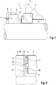
- the mechanical seal arrangement 1 comprises a mechanical seal with a rotating sliding ring 3 and a stationary sliding ring 2.
- One of the two sliding rings has a flat first sliding surface and the other of the two sliding rings has a second sliding surface with a circumferentially closed sealing edge 22 on.
- the mechanical seal seals between a product side 8 and an atmosphere side 9.
- the flat first sliding surface 30 is formed on the rotating sliding ring 3.
- a second sliding surface 20 with the cutting edge 22 is formed on the stationary sliding ring 2.
- the cutting edge 22 is arranged centrally in the radial direction of the stationary sliding ring 2. I.e. a first distance A1 from the cutting edge 22 to the inner circumference of the stationary seal ring is equal to a second radial distance A2 from the cutting edge 22 to the outer circumference of the stationary seal ring 2.
- the stationary sliding ring 2 has a base region 21 and the sealing cutting edge 22.
- the cutting edge 22 thus divides the base area 21 into a first base part area 21a and a second base part area 21b.
- the areas of the first and second basic partial areas 21a, 21b are the same.
- the ring widths of the first and second basic partial areas 21a, 21b are the same.
- the sealing cutting edge 22 is shown on a greatly enlarged scale in the figures in order to make the invention easier to recognize.
- the cutting edge 22 actually has a width B in a range from 10 to 500 ⁇ m and preferably has a width B of less than or equal to 60 ⁇ m. I.e. the sealing edge 22 has a width B (see Figures 3 and 4 ), which is smaller than an average width of a human hair, which is approximately 100 ⁇ m.
- the cutting edge 22 has a height H from the base region 21 which is in the range from 3 to 5 ⁇ m.
- the width B of the sealing edge 22 is less than 1% of the total width B0, preferably less than 0.6% of the total width B0 of the second sliding surface 20.
- the first sliding surface 30 is flat (cf. Figure 2 ) and preferably has a circular flatness of less than or equal to 0.5 ⁇ m. Furthermore, the first sliding surface 30 of the rotating sliding ring 3 has an average roughness Ra of less than or equal to 0.02 ⁇ m, preferably less than or equal to 0.01 ⁇ m. The first sliding surface 30 is coated with a diamond coating 12.
- the stationary sliding ring 2 is fixed on a housing 5 and the rotating sliding ring 3 is arranged on a shaft 7 by means of a driver 6 and rotates with it.
- a preloading element 4 is provided which exerts a preloading force F on the rotating slide ring 3. This results between the stationary seal ring 2 and the rotating sliding ring 3 is a contact pressure between the sealing edge 22 and the first flat sliding surface 30, which is preferably in a range between 10 x 10 5 Pa and 1,000 x 10 5 Pa.
- the first sliding surface 30 of the rotating sliding ring 3 is preferably polished in order to have the lowest possible mean roughness.
- the cutting edge 22 is designed such that a ratio of the height H to the width B is in a range from 0.002 to 2.
- a load factor (k factor) for the mechanical seal is in a range from 0 to 0.3.
- the load factor k is a dimensionless geometric parameter that defines the area ratio of the mechanical seal and is defined as the ratio of the hydraulically loaded area to the contact area on the slip ring surfaces.
- both the first sliding surface 30 and the second sliding surface 20 each have a diamond coating 11, 12.
- the cutting edge 22 is made entirely of diamond material.
- the first and second sliding surfaces are made of cubic boron nitride and the sealing edge 22 is alternatively also made entirely of cubic boron nitride.
- the sealing edge 22 thus provides a contact surface 13 for the sliding process on the first sliding surface 30.
- a thickness of the diamond coating 11, 12 on the sliding rings is approximately 8 ⁇ m.
- the height H of the sealing edge 22 is thus smaller than the thickness of the coating on a substrate which defines the base ring.
- an OH - ion dispenser 10 and / or an H + ion dispenser 10 is provided between the contact surfaces of the sliding rings.
- water is provided here.
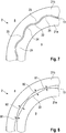
- Figure 6 shows a mechanical seal arrangement according to a second embodiment of the invention.
- the cutting edge 22 in this embodiment is not circular, as in the first embodiment, but has a crenellated shape. This results in first pockets 23 pointing outwards in the radial direction and second pockets 24 pointing inwards in the radial direction Figure 6
- the first and second pockets are provided of different sizes.
- the first pockets 23 are larger than the second pockets 24.
- the first pockets 23 have a first length U1 in the circumferential direction, which is twice as large as a second length U2 of the second pockets 24 in the circumferential direction.
- the length of the pockets in the circumferential direction is measured at the foot of each pocket.
- the first and second pockets 23, 24 on the cutting edge 22 have the effect that, in contrast to a circular design, the provision of OH - ions and / or H + ions on the sliding surfaces is improved.
- the OH - ion donor and / or the H + ion donor can be stored directly adjacent to the sealing edge 22.
- an overall length of the sealing edge is longer than in comparison with a circular cutting edge. Otherwise, the same advantages as in the first embodiment are obtained.
- Figure 7 shows a mechanical seal arrangement according to a third embodiment of the present invention.
- the cutting edge 22 is provided in such a way that the cutting edge 22 has a sinusoidal geometric shape. This also results in first and second pockets 23, 24 on the sealing cutting edge 22. This also results in a longer sealing length compared with a circular sealing cutting edge.
- the pockets have the same function as in the second embodiment.
- Figure 8 shows a mechanical seal arrangement according to a fourth embodiment of the present invention.
- the sealing edge 22 has a regularly varying width.
- the narrowest width the sealing edge 22 is identified with the reference symbol B1 and the widest point of the sealing edge 22 is identified with the reference symbol B2.
- the small width B1 corresponds to half of the large width B2.
- the varying width is regularly provided.
- this cutting edge 22 can be generated by two sinusoidal curves running offset from one another by 180 °, which form the walls of the cutting edge 22.
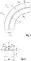
- Figure 9 shows a mechanical seal arrangement with a stationary sliding ring 2 according to a fifth embodiment of the invention.
- the stationary sliding ring 2 has a circular sealing cutting edge 22.
- support structures 25 are additionally provided on the first and second base regions 21a, 21b.
- the support structures 25 have a rectangular basic shape and furthermore have a height which is equal to the height of the sealing edge 22.
- the support structures ensure during operation that radial tilting of the sliding rings is avoided. As a result, a sealing gap in the range of 3 ⁇ can be ensured during operation.
- the support structures 25 are provided from the same material as the coating of the stationary sliding ring 2, preferably from diamond.
- the support structures 25 are each provided individually on the base region 21. Alternatively, the support structures can also be connected to the sealing disk 22.
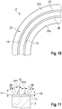
- the Figures 10 and 11 show a mechanical seal arrangement with a stationary sliding ring 2 according to a sixth embodiment of the invention.
- the stationary sliding ring 2 has a first cutting edge 22 and a second cutting edge 26.
- the two sealing cutting edges 22, 26 are each provided in a circle.
- the first sealing edge 22 has a greater height H1 than the height H2 of the second sealing edge 26 (see FIG Figure 11 ).
- the second cutting edge 26 thus serves as a reserve cutting edge if the first cutting edge 22 is damaged.
- a first width B11 of the first sealing blade 22 is equal to a second width B12 of the second sealing blade 26.
- the sealing blades 22, 26 are preferably provided symmetrically on the stationary sliding ring 2.
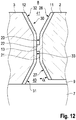
- the Figure 12 shows a mechanical seal arrangement according to a seventh embodiment of the invention.
- the sliding surfaces of the stationary sliding ring 2 of the rotating sliding ring 3 each have three areas. More precisely, the stationary seal ring 2 has a first tapering area 27 and a second tapering area 28. Between the two tapering areas 27, 28, a flat base area 21 is provided which has the sealing edge 22 (cf. Fig. 12 ). The two tapering areas 27, 28 taper starting from the base area 21.
- the first sliding surface 30 of the rotating sliding ring 3 is constructed in the same way as the sliding surface of the stationary sliding ring 2. More precisely, the first sliding surface 30 has a first tapering area 31, a second tapering area 32 and a flat area 33 arranged between the two tapering areas 31, 32. How out Fig. 12 As can be seen, this results in an inner space 40 on the inner circumference of the slip rings and an outer space 41 on the outer circumference of the slip rings.
- the tapering areas are conical.
- An angle ⁇ of the conically tapering areas is chosen to be the same in each case. This results in inner and outer spaces 40, 41 of equal size.
- the cutting edge 22 is arranged in the middle of the flat base area 21 on the second sliding surface 20.
- the two tapering areas 27, 28 and the flat base area 21 on the first sliding ring 2 have approximately the same width in the radial direction.
- the widths of the first and second tapering areas 31, 32 and of the flat area 33 on the rotating seal ring 3 are each provided with a third of the total width.
- an area on the slip rings which are directly opposite one another can be reduced.
- the sealing cutting edge 22 thus makes it possible to reduce the size of the surfaces directly opposite one another and thus to reduce losses during operation.
- the sealing cutting edges 22 are each provided on the stationary sliding ring 2 and the rotating sliding ring 3 has a flat first sliding surface 30. According to the invention, however, it is also possible that the sealing cutting edges are provided on the first sliding surface 30 of the rotating sliding ring 3 and the second sliding surface 20 of the stationary sliding ring 2 is designed as a flat surface. In other words, the invention functions independently of which of the sliding surfaces of the sliding rings has the sealing edge 22 and which of the sliding surfaces is the flat sliding surface.
Landscapes
- Engineering & Computer Science (AREA)
- General Engineering & Computer Science (AREA)
- Mechanical Engineering (AREA)
- Mechanical Sealing (AREA)
Priority Applications (1)
| Application Number | Priority Date | Filing Date | Title |
|---|---|---|---|
| PL17780345T PL3548779T3 (pl) | 2016-11-29 | 2017-09-26 | Układ uszczelnienia pierścieniami ślizgowymi o minimalnym przecieku |
Applications Claiming Priority (2)
| Application Number | Priority Date | Filing Date | Title |
|---|---|---|---|
| DE102016223636.9A DE102016223636B3 (de) | 2016-11-29 | 2016-11-29 | Gleitringdichtungsanordnung mit minimaler Leckage |
| PCT/EP2017/074343 WO2018099627A1 (de) | 2016-11-29 | 2017-09-26 | Gleitringdichtungsanordnung mit minimaler leckage |
Publications (2)
| Publication Number | Publication Date |
|---|---|
| EP3548779A1 EP3548779A1 (de) | 2019-10-09 |
| EP3548779B1 true EP3548779B1 (de) | 2020-09-16 |
Family
ID=60022067
Family Applications (1)
| Application Number | Title | Priority Date | Filing Date |
|---|---|---|---|
| EP17780345.9A Active EP3548779B1 (de) | 2016-11-29 | 2017-09-26 | Gleitringdichtungsanordnung mit minimaler leckage |
Country Status (8)
| Country | Link |
|---|---|
| US (1) | US11028926B2 (pl) |
| EP (1) | EP3548779B1 (pl) |
| CN (1) | CN110023657B (pl) |
| DE (1) | DE102016223636B3 (pl) |
| DK (1) | DK3548779T3 (pl) |
| ES (1) | ES2826989T3 (pl) |
| PL (1) | PL3548779T3 (pl) |
| WO (1) | WO2018099627A1 (pl) |
Families Citing this family (7)
| Publication number | Priority date | Publication date | Assignee | Title |
|---|---|---|---|---|
| US11473679B2 (en) | 2017-03-20 | 2022-10-18 | Flowserve Management Company | Shock wave mechanical seal |
| RU2690287C1 (ru) * | 2018-06-27 | 2019-05-31 | Акционерное общество "Центральное конструкторское бюро машиностроения" (АО "ЦКБМ") | Элемент пары трения торцового уплотнения |
| DE102019219422A1 (de) * | 2019-12-12 | 2021-06-17 | Eagleburgmann Germany Gmbh & Co. Kg | Gleitringdichtung mit Überwachungsfunktion sowie Verfahren hierzu |
| DE102020203764A1 (de) * | 2020-03-24 | 2021-09-30 | Eagleburgmann Germany Gmbh & Co. Kg | Gleitringdichtung mit verbesserter Nutanordnung |
| EP4177487A4 (en) * | 2020-07-06 | 2024-07-24 | Eagle Industry Co., Ltd. | SLIDING COMPONENT |
| CN114087367B (zh) * | 2021-11-26 | 2024-01-23 | 中国科学院工程热物理研究所 | 一种磁悬浮干气密封系统 |
| WO2023217406A1 (en) | 2022-05-09 | 2023-11-16 | Oerlikon Surface Solutions Ag, Pfäffikon | Amorphous carbon coating for reduction of friction and wear in a slide component |
Family Cites Families (11)
| Publication number | Priority date | Publication date | Assignee | Title |
|---|---|---|---|---|
| DE900766C (de) | 1938-05-24 | 1954-01-04 | Hans Ziller | Abdichtung fuer Waelzlager |
| DE1941675B2 (de) * | 1969-08-16 | 1971-12-23 | Kupfer Asbest Co Gustav Bach, 7100 Heilbronn | Dichtmanschette fuer eine radial wellendichtring |
| US4335888A (en) * | 1978-03-20 | 1982-06-22 | Nippon Pillar Packing Co. Ltd. | Mechanical seal |
| US6494462B2 (en) * | 1998-05-06 | 2002-12-17 | Kalsi Engineering, Inc. | Rotary seal with improved dynamic interface |
| DE29908918U1 (de) * | 1999-05-20 | 1999-07-29 | Feodor Burgmann Dichtungswerke GmbH & Co, 82515 Wolfratshausen | Gleitringdichtungsanordnung |
| JP3933469B2 (ja) * | 2001-12-28 | 2007-06-20 | イーグル工業株式会社 | メカニカルシール装置 |
| DE202006006425U1 (de) * | 2006-04-21 | 2006-06-29 | Burgmann Industries Gmbh & Co. Kg | Bauteil, insbesondere Gleitring einer Gleitringdichtungsanordnung |
| DE202010011173U1 (de) * | 2010-08-09 | 2011-12-22 | Eagleburgmann Germany Gmbh & Co. Kg | Gleitring mit verbesserten Einlaufeigenschaften |
| DE102013005926B4 (de) * | 2013-04-04 | 2015-12-03 | Eagleburgmann Germany Gmbh & Co. Kg | Gleitringdichtungsanordnung mit unterschiedlich harten Gleitflächen |
| DE102013223226B4 (de) * | 2013-11-14 | 2015-09-17 | Eagleburgmann Germany Gmbh & Co. Kg | Gleitringdichtungsanordnung mit verbessertem Abströmverhalten eines Kühl- und/oder Sperrmediums |
| DE102014203569B3 (de) * | 2014-02-27 | 2015-02-26 | Condias Gmbh | Gleitringdichtungsanordnung mit OH-Radikal-Erzeugungsvorrichtung |
-
2016
- 2016-11-29 DE DE102016223636.9A patent/DE102016223636B3/de not_active Expired - Fee Related
-
2017
- 2017-09-26 ES ES17780345T patent/ES2826989T3/es active Active
- 2017-09-26 PL PL17780345T patent/PL3548779T3/pl unknown
- 2017-09-26 US US16/464,043 patent/US11028926B2/en active Active
- 2017-09-26 DK DK17780345.9T patent/DK3548779T3/da active
- 2017-09-26 EP EP17780345.9A patent/EP3548779B1/de active Active
- 2017-09-26 CN CN201780073692.4A patent/CN110023657B/zh active Active
- 2017-09-26 WO PCT/EP2017/074343 patent/WO2018099627A1/de not_active Ceased
Non-Patent Citations (1)
| Title |
|---|
| None * |
Also Published As
| Publication number | Publication date |
|---|---|
| PL3548779T3 (pl) | 2021-04-19 |
| DK3548779T3 (da) | 2020-12-14 |
| DE102016223636B3 (de) | 2018-05-17 |
| CN110023657B (zh) | 2020-06-30 |
| US20190383397A1 (en) | 2019-12-19 |
| ES2826989T3 (es) | 2021-05-19 |
| CN110023657A (zh) | 2019-07-16 |
| EP3548779A1 (de) | 2019-10-09 |
| WO2018099627A1 (de) | 2018-06-07 |
| US11028926B2 (en) | 2021-06-08 |
Similar Documents
| Publication | Publication Date | Title |
|---|---|---|
| EP3548779B1 (de) | Gleitringdichtungsanordnung mit minimaler leckage | |
| DE69016253T2 (de) | Drehrichtungsunabhängige kontaktlose Gleitringdichtung. | |
| DE112005000997B4 (de) | Gasdichtungseinrichtung | |
| DE102012022465B4 (de) | Gleitringdichtungsanordnung mit verbesserter Nebendichtung | |
| DE3201862C2 (de) | Berührungsfreie Dichtung | |
| EP2063157B1 (de) | Gleitringdichtungsanordnung | |
| DE3779709T2 (de) | Axiallager mit kippsegmenten mit optimaler lokalisierung der kippachse. | |
| DE2146026C2 (de) | Wellendichtungsanordnung | |
| DE69424956T2 (de) | Wellendichtung | |
| EP2063156B1 (de) | Doppel-Dichtungsanordnung | |
| DE3201860A1 (de) | "beruehrungsfreie dichtung" | |
| DE4209484A1 (de) | Gleitringdichtung mit Rückförderwirkung | |
| EP0274090A2 (de) | Dichtung | |
| DE2909331A1 (de) | Dichtungsvorrichtung | |
| DE3217118C1 (de) | Dichtungsanordnung für Wellen | |
| DE69618355T2 (de) | Wellendichtung | |
| EP0491771B1 (de) | Dichtungsanordnung | |
| EP0708897B1 (de) | Dichtungsanordnung | |
| EP2976557A2 (de) | Dichtelement | |
| EP0573539B1 (de) | Dichtungsanordnung | |
| DE2436992A1 (de) | Federnde dichtung | |
| DE19723962C2 (de) | Doppelplattenschieber | |
| DE202008011032U1 (de) | Gleitringdichtungsanordnung mit verbesserter Nebendichtung | |
| DE29818004U1 (de) | Drosselspalt-Dichtungsanordnung für die Abdichtung gasförmiger Medien | |
| DE102010024291A1 (de) | Gleitringdichtung mit rotierendem Gegenring mit exakt definierter Einspannung |
Legal Events
| Date | Code | Title | Description |
|---|---|---|---|
| STAA | Information on the status of an ep patent application or granted ep patent |
Free format text: STATUS: UNKNOWN |
|
| STAA | Information on the status of an ep patent application or granted ep patent |
Free format text: STATUS: THE INTERNATIONAL PUBLICATION HAS BEEN MADE |
|
| PUAI | Public reference made under article 153(3) epc to a published international application that has entered the european phase |
Free format text: ORIGINAL CODE: 0009012 |
|
| STAA | Information on the status of an ep patent application or granted ep patent |
Free format text: STATUS: REQUEST FOR EXAMINATION WAS MADE |
|
| 17P | Request for examination filed |
Effective date: 20190425 |
|
| AK | Designated contracting states |
Kind code of ref document: A1 Designated state(s): AL AT BE BG CH CY CZ DE DK EE ES FI FR GB GR HR HU IE IS IT LI LT LU LV MC MK MT NL NO PL PT RO RS SE SI SK SM TR |
|
| AX | Request for extension of the european patent |
Extension state: BA ME |
|
| DAV | Request for validation of the european patent (deleted) | ||
| DAX | Request for extension of the european patent (deleted) | ||
| GRAJ | Information related to disapproval of communication of intention to grant by the applicant or resumption of examination proceedings by the epo deleted |
Free format text: ORIGINAL CODE: EPIDOSDIGR1 |
|
| GRAP | Despatch of communication of intention to grant a patent |
Free format text: ORIGINAL CODE: EPIDOSNIGR1 |
|
| GRAP | Despatch of communication of intention to grant a patent |
Free format text: ORIGINAL CODE: EPIDOSNIGR1 |
|
| STAA | Information on the status of an ep patent application or granted ep patent |
Free format text: STATUS: GRANT OF PATENT IS INTENDED |
|
| INTG | Intention to grant announced |
Effective date: 20200514 |
|
| GRAS | Grant fee paid |
Free format text: ORIGINAL CODE: EPIDOSNIGR3 |
|
| GRAA | (expected) grant |
Free format text: ORIGINAL CODE: 0009210 |
|
| STAA | Information on the status of an ep patent application or granted ep patent |
Free format text: STATUS: THE PATENT HAS BEEN GRANTED |
|
| AK | Designated contracting states |
Kind code of ref document: B1 Designated state(s): AL AT BE BG CH CY CZ DE DK EE ES FI FR GB GR HR HU IE IS IT LI LT LU LV MC MK MT NL NO PL PT RO RS SE SI SK SM TR |
|
| REG | Reference to a national code |
Ref country code: GB Ref legal event code: FG4D Free format text: NOT ENGLISH |
|
| REG | Reference to a national code |
Ref country code: CH Ref legal event code: EP |
|
| REG | Reference to a national code |
Ref country code: DE Ref legal event code: R096 Ref document number: 502017007320 Country of ref document: DE |
|
| REG | Reference to a national code |
Ref country code: IE Ref legal event code: FG4D Free format text: LANGUAGE OF EP DOCUMENT: GERMAN |
|
| REG | Reference to a national code |
Ref country code: AT Ref legal event code: REF Ref document number: 1314456 Country of ref document: AT Kind code of ref document: T Effective date: 20201015 |
|
| REG | Reference to a national code |
Ref country code: NL Ref legal event code: FP |
|
| REG | Reference to a national code |
Ref country code: DK Ref legal event code: T3 Effective date: 20201208 |
|
| REG | Reference to a national code |
Ref country code: SE Ref legal event code: TRGR |
|
| PG25 | Lapsed in a contracting state [announced via postgrant information from national office to epo] |
Ref country code: BG Free format text: LAPSE BECAUSE OF FAILURE TO SUBMIT A TRANSLATION OF THE DESCRIPTION OR TO PAY THE FEE WITHIN THE PRESCRIBED TIME-LIMIT Effective date: 20201216 Ref country code: GR Free format text: LAPSE BECAUSE OF FAILURE TO SUBMIT A TRANSLATION OF THE DESCRIPTION OR TO PAY THE FEE WITHIN THE PRESCRIBED TIME-LIMIT Effective date: 20201217 Ref country code: HR Free format text: LAPSE BECAUSE OF FAILURE TO SUBMIT A TRANSLATION OF THE DESCRIPTION OR TO PAY THE FEE WITHIN THE PRESCRIBED TIME-LIMIT Effective date: 20200916 Ref country code: NO Free format text: LAPSE BECAUSE OF FAILURE TO SUBMIT A TRANSLATION OF THE DESCRIPTION OR TO PAY THE FEE WITHIN THE PRESCRIBED TIME-LIMIT Effective date: 20201216 Ref country code: FI Free format text: LAPSE BECAUSE OF FAILURE TO SUBMIT A TRANSLATION OF THE DESCRIPTION OR TO PAY THE FEE WITHIN THE PRESCRIBED TIME-LIMIT Effective date: 20200916 |
|
| PG25 | Lapsed in a contracting state [announced via postgrant information from national office to epo] |
Ref country code: RS Free format text: LAPSE BECAUSE OF FAILURE TO SUBMIT A TRANSLATION OF THE DESCRIPTION OR TO PAY THE FEE WITHIN THE PRESCRIBED TIME-LIMIT Effective date: 20200916 Ref country code: LV Free format text: LAPSE BECAUSE OF FAILURE TO SUBMIT A TRANSLATION OF THE DESCRIPTION OR TO PAY THE FEE WITHIN THE PRESCRIBED TIME-LIMIT Effective date: 20200916 |
|
| REG | Reference to a national code |
Ref country code: LT Ref legal event code: MG4D |
|
| PG25 | Lapsed in a contracting state [announced via postgrant information from national office to epo] |
Ref country code: EE Free format text: LAPSE BECAUSE OF FAILURE TO SUBMIT A TRANSLATION OF THE DESCRIPTION OR TO PAY THE FEE WITHIN THE PRESCRIBED TIME-LIMIT Effective date: 20200916 Ref country code: RO Free format text: LAPSE BECAUSE OF FAILURE TO SUBMIT A TRANSLATION OF THE DESCRIPTION OR TO PAY THE FEE WITHIN THE PRESCRIBED TIME-LIMIT Effective date: 20200916 Ref country code: PT Free format text: LAPSE BECAUSE OF FAILURE TO SUBMIT A TRANSLATION OF THE DESCRIPTION OR TO PAY THE FEE WITHIN THE PRESCRIBED TIME-LIMIT Effective date: 20210118 Ref country code: LT Free format text: LAPSE BECAUSE OF FAILURE TO SUBMIT A TRANSLATION OF THE DESCRIPTION OR TO PAY THE FEE WITHIN THE PRESCRIBED TIME-LIMIT Effective date: 20200916 Ref country code: SM Free format text: LAPSE BECAUSE OF FAILURE TO SUBMIT A TRANSLATION OF THE DESCRIPTION OR TO PAY THE FEE WITHIN THE PRESCRIBED TIME-LIMIT Effective date: 20200916 |
|
| REG | Reference to a national code |
Ref country code: CH Ref legal event code: PL |
|
| REG | Reference to a national code |
Ref country code: ES Ref legal event code: FG2A Ref document number: 2826989 Country of ref document: ES Kind code of ref document: T3 Effective date: 20210519 |
|
| PG25 | Lapsed in a contracting state [announced via postgrant information from national office to epo] |
Ref country code: IS Free format text: LAPSE BECAUSE OF FAILURE TO SUBMIT A TRANSLATION OF THE DESCRIPTION OR TO PAY THE FEE WITHIN THE PRESCRIBED TIME-LIMIT Effective date: 20210116 Ref country code: PL Free format text: LAPSE BECAUSE OF FAILURE TO SUBMIT A TRANSLATION OF THE DESCRIPTION OR TO PAY THE FEE WITHIN THE PRESCRIBED TIME-LIMIT Effective date: 20200916 Ref country code: AL Free format text: LAPSE BECAUSE OF FAILURE TO SUBMIT A TRANSLATION OF THE DESCRIPTION OR TO PAY THE FEE WITHIN THE PRESCRIBED TIME-LIMIT Effective date: 20200916 |
|
| REG | Reference to a national code |
Ref country code: DE Ref legal event code: R097 Ref document number: 502017007320 Country of ref document: DE |
|
| REG | Reference to a national code |
Ref country code: BE Ref legal event code: MM Effective date: 20200930 |
|
| PG25 | Lapsed in a contracting state [announced via postgrant information from national office to epo] |
Ref country code: LU Free format text: LAPSE BECAUSE OF NON-PAYMENT OF DUE FEES Effective date: 20200926 Ref country code: MC Free format text: LAPSE BECAUSE OF FAILURE TO SUBMIT A TRANSLATION OF THE DESCRIPTION OR TO PAY THE FEE WITHIN THE PRESCRIBED TIME-LIMIT Effective date: 20200916 Ref country code: SK Free format text: LAPSE BECAUSE OF FAILURE TO SUBMIT A TRANSLATION OF THE DESCRIPTION OR TO PAY THE FEE WITHIN THE PRESCRIBED TIME-LIMIT Effective date: 20200916 |
|
| PLBE | No opposition filed within time limit |
Free format text: ORIGINAL CODE: 0009261 |
|
| STAA | Information on the status of an ep patent application or granted ep patent |
Free format text: STATUS: NO OPPOSITION FILED WITHIN TIME LIMIT |
|
| 26N | No opposition filed |
Effective date: 20210617 |
|
| PG25 | Lapsed in a contracting state [announced via postgrant information from national office to epo] |
Ref country code: IE Free format text: LAPSE BECAUSE OF NON-PAYMENT OF DUE FEES Effective date: 20200926 Ref country code: LI Free format text: LAPSE BECAUSE OF NON-PAYMENT OF DUE FEES Effective date: 20200930 Ref country code: SI Free format text: LAPSE BECAUSE OF FAILURE TO SUBMIT A TRANSLATION OF THE DESCRIPTION OR TO PAY THE FEE WITHIN THE PRESCRIBED TIME-LIMIT Effective date: 20200916 Ref country code: BE Free format text: LAPSE BECAUSE OF NON-PAYMENT OF DUE FEES Effective date: 20200930 Ref country code: CH Free format text: LAPSE BECAUSE OF NON-PAYMENT OF DUE FEES Effective date: 20200930 |
|
| PG25 | Lapsed in a contracting state [announced via postgrant information from national office to epo] |
Ref country code: TR Free format text: LAPSE BECAUSE OF FAILURE TO SUBMIT A TRANSLATION OF THE DESCRIPTION OR TO PAY THE FEE WITHIN THE PRESCRIBED TIME-LIMIT Effective date: 20200916 Ref country code: MT Free format text: LAPSE BECAUSE OF FAILURE TO SUBMIT A TRANSLATION OF THE DESCRIPTION OR TO PAY THE FEE WITHIN THE PRESCRIBED TIME-LIMIT Effective date: 20200916 Ref country code: CY Free format text: LAPSE BECAUSE OF FAILURE TO SUBMIT A TRANSLATION OF THE DESCRIPTION OR TO PAY THE FEE WITHIN THE PRESCRIBED TIME-LIMIT Effective date: 20200916 |
|
| PG25 | Lapsed in a contracting state [announced via postgrant information from national office to epo] |
Ref country code: MK Free format text: LAPSE BECAUSE OF FAILURE TO SUBMIT A TRANSLATION OF THE DESCRIPTION OR TO PAY THE FEE WITHIN THE PRESCRIBED TIME-LIMIT Effective date: 20200916 |
|
| P01 | Opt-out of the competence of the unified patent court (upc) registered |
Effective date: 20230426 |
|
| REG | Reference to a national code |
Ref country code: AT Ref legal event code: MM01 Ref document number: 1314456 Country of ref document: AT Kind code of ref document: T Effective date: 20220926 |
|
| PG25 | Lapsed in a contracting state [announced via postgrant information from national office to epo] |
Ref country code: AT Free format text: LAPSE BECAUSE OF NON-PAYMENT OF DUE FEES Effective date: 20220926 |
|
| PGFP | Annual fee paid to national office [announced via postgrant information from national office to epo] |
Ref country code: ES Payment date: 20241018 Year of fee payment: 8 Ref country code: IT Payment date: 20240930 Year of fee payment: 8 |
|
| PGFP | Annual fee paid to national office [announced via postgrant information from national office to epo] |
Ref country code: DK Payment date: 20250922 Year of fee payment: 9 Ref country code: DE Payment date: 20250919 Year of fee payment: 9 |
|
| PGFP | Annual fee paid to national office [announced via postgrant information from national office to epo] |
Ref country code: PL Payment date: 20250915 Year of fee payment: 9 Ref country code: NL Payment date: 20250922 Year of fee payment: 9 |
|
| PGFP | Annual fee paid to national office [announced via postgrant information from national office to epo] |
Ref country code: GB Payment date: 20250923 Year of fee payment: 9 |
|
| PGFP | Annual fee paid to national office [announced via postgrant information from national office to epo] |
Ref country code: FR Payment date: 20250926 Year of fee payment: 9 |
|
| PGFP | Annual fee paid to national office [announced via postgrant information from national office to epo] |
Ref country code: SE Payment date: 20250922 Year of fee payment: 9 |
|
| PGFP | Annual fee paid to national office [announced via postgrant information from national office to epo] |
Ref country code: CZ Payment date: 20250912 Year of fee payment: 9 |